NUMERICAL STUDIES ON STABILITY OF SLENDER SUPPORTING ...
9
Journal of Applied Mathematics and Computational Mechanics 2016, 15(2), 157-165 www.amcm.pcz.pl p-ISSN 2299-9965 DOI: 10.17512/jamcm.2016.2.17 e-ISSN 2353-0588 NUMERICAL STUDIES ON STABILITY OF SLENDER SUPPORTING STRUCTURES Krzysztof Sokól, Sebastian Uzny Institute of Mechanics and Machine Design Foundation, Czestochowa University of Technology Częstochowa, Poland [email protected], [email protected] Abstract. In this paper the results of studies on stability of the geometrically non-linear column (slender system) composed of two rods have been presented. The supporting struc- ture has a defect in the form of cracks which are present in each of rods. The cracks are simulated by means of rotational springs. On the basis of the total potential energy princi- ple, the boundary problem is being formulated. The results show an influence of the crack size on the stability of the column in particular on bifurcation load magnitude. Keywords: stability, cracks, bifurcation load, slender systems, column 1. Introduction The considered columns are classified as slender supporting systems due to relation between cross-section dimensions and the total length of the structure. In these types of systems the most undesirable phenomena are: flutter instability, buckling and non-axially applied external load. The presence of the cracks is also very dangerous due to its influence on the dynamic as well as on static behaviour of the structure. At the static investigations the presence of a crack affects the loading capacity, but what is important is that the capacity may differ depending on crack location. The crack influence on stability as well as static and dynamic behavior, was dis- cussed and presented in many scientific papers in recent years. Dimarogonas and Anifantis in [1] have studied the stability of beam structures subjected to follower and vertical loads. The crack was modelled by a general flexibility matrix which expressed the local flexibility of the beam. The same author in [2] introduced the Rayleigh principle for an estimation of the change of the natural frequencies as well as modes of vibration of the structure with a crack. Bergman and Lee [3] have studied the stepped beams and rectangular plates. Chondros [4] has performed theoretical, numerical and experimental studies of cracked aluminum beams. Binici in [5] has studied single beams in which the multiple cracks were modeled with rotational springs. Sokól [6] presented investigations on an influence of single crack presence in the cantilever column on vibrations and stability as well as on the
Transcript of NUMERICAL STUDIES ON STABILITY OF SLENDER SUPPORTING ...

Journal of Applied Mathematics and Computational Mechanics 2016, 15(2), 157-165
www.amcm.pcz.pl p-ISSN 2299-9965
DOI: 10.17512/jamcm.2016.2.17 e-ISSN 2353-0588
NUMERICAL STUDIES ON STABILITY OF SLENDER
SUPPORTING STRUCTURES
Krzysztof Sokół, Sebastian Uzny
Institute of Mechanics and Machine Design Foundation, Czestochowa University of Technology Częstochowa, Poland
[email protected], [email protected]
Abstract. In this paper the results of studies on stability of the geometrically non-linear
column (slender system) composed of two rods have been presented. The supporting struc-
ture has a defect in the form of cracks which are present in each of rods. The cracks are
simulated by means of rotational springs. On the basis of the total potential energy princi-
ple, the boundary problem is being formulated. The results show an influence of the crack
size on the stability of the column in particular on bifurcation load magnitude.
Keywords: stability, cracks, bifurcation load, slender systems, column
1. Introduction
The considered columns are classified as slender supporting systems due to
relation between cross-section dimensions and the total length of the structure.
In these types of systems the most undesirable phenomena are: flutter instability,
buckling and non-axially applied external load. The presence of the cracks is also
very dangerous due to its influence on the dynamic as well as on static behaviour
of the structure. At the static investigations the presence of a crack affects the
loading capacity, but what is important is that the capacity may differ depending
on crack location.
The crack influence on stability as well as static and dynamic behavior, was dis-
cussed and presented in many scientific papers in recent years. Dimarogonas and
Anifantis in [1] have studied the stability of beam structures subjected to follower
and vertical loads. The crack was modelled by a general flexibility matrix which
expressed the local flexibility of the beam. The same author in [2] introduced
the Rayleigh principle for an estimation of the change of the natural frequencies
as well as modes of vibration of the structure with a crack. Bergman and Lee [3]
have studied the stepped beams and rectangular plates. Chondros [4] has performed
theoretical, numerical and experimental studies of cracked aluminum beams. Binici
in [5] has studied single beams in which the multiple cracks were modeled with
rotational springs. Sokół [6] presented investigations on an influence of single
crack presence in the cantilever column on vibrations and stability as well as on the
K. Sokół, S. Uzny 158
amplitude - vibration frequency relationship. Mostly the traditional analysis [7]
was performed but Sokół and Kulawik [8] have proposed an implementation of
genetic algorithms in order to find optimum parameters of the system at which
the structure will be the least sensitive to the crack presence. In the literature two
different types of problems are studied that take cracks into account. The first one
is focused on linear problems where the cracks always remain open. The second
one takes into account the non-linear problems where the crack opens and closes
in time. In the numerical simulations of cracks the different approach can be found:
reduction of the cross-section area, definition of complex mathematical functions
or introduction of rotational springs. The studies performed by Chondros et al. [9]
and Arif Gurel [10] show that despite rotational spring simplicity the comparison
of the data of numerical simulations and experimental studies leads to accuracy
of good results.
In most scientific papers, the single linear columns and beams with cracks are
presented. In this paper, the multi-member non-linear column with a crack in each
of rods is investigated. The boundary problem of multi-member systems is formu-
lated on the basis of the non-linear differential equations. In this case, the non-linear
relation strain - transversal deflection is used. The systems are characterized by the
presence of rectilinear and curvilinear form of static equilibrium. The presence of
both forms depends on the magnitude of the applied external load. Many scientific
papers can be found where the phenomenon of the change of the static equilibrium
form takes place along with the presence of the local and global instability regions
(see [11, 12]). The external load is being realized by means of an axially applied
external force with a constant line of action (Euler’s load). The proposed method
of boundary problem formulation can be easily adapted to the more complicated
structures, such as flat frames composed of n-elements. The main purpose of this
paper is to present an influence of the crack size and location on loading capacity.
The considered crack is present in both rods of the structure. Due to investigations
of a multi-cracked system the contour graphs are used in order to achieve the best
method of presentation. The results of simulations allow one to see the areas
of special care in which the appearance of the crack will quickly lead to destruction
of the structure.
2. Boundary problem formulation
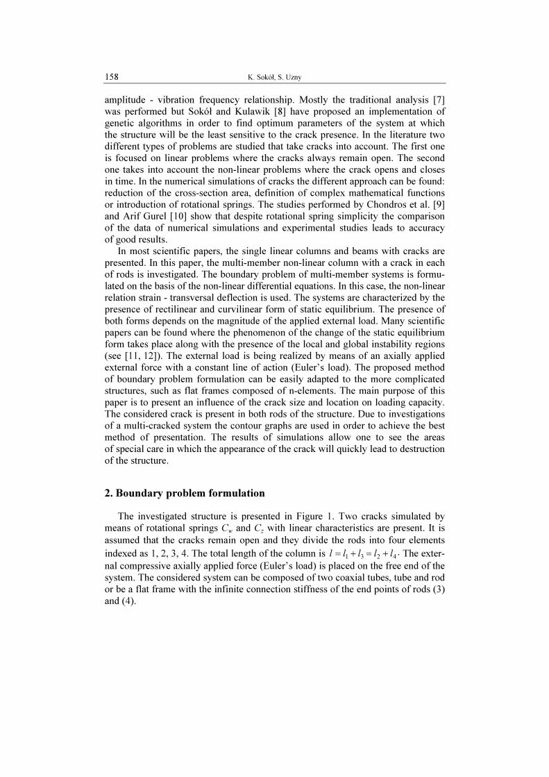
The investigated structure is presented in Figure 1. Two cracks simulated by
means of rotational springs Cw and C
z with linear characteristics are present. It is
assumed that the cracks remain open and they divide the rods into four elements
indexed as 1, 2, 3, 4. The total length of the column is 4231lllll +=+= . The exter-
nal compressive axially applied force (Euler’s load) is placed on the free end of the
system. The considered system can be composed of two coaxial tubes, tube and rod
or be a flat frame with the infinite connection stiffness of the end points of rods (3)
and (4).

Numerical studies on stability of slender supporting structures 159
W1(x1),
W2(x2)
W3(x3)
x1, x2
x3
Rod(2)
E2, J2, A2
Rod (4) E4, J4, A4
Rod (3) E3, J3, A3
Cw
P
l4
l2
l
Cz
l3
l1 Rod(1)
E1, J1, A1
Fig. 1. Investigated system
The boundary problem has been formulated on the basis of static criterion of
stability (δV = 0) where the potential energy V of the system is given by the follow-
ing formula:
( ) ( )
( )lPU
dx
xdW
dx
xdWC
dx
xdW
dx
xdWC
dxdx
xdW
dx
xdUEAdx
xd
xWdEJV
x
lx
w
x
lx
z
i
l
i
ii
i
ii
i
i
l
i
i
i
ii
3
2
04
44
2
22
2
03
33
1
11
4
1 0
22
4
1 0
2
2
2
4
22
3
11
)()(
2
1)()(
2
1
)(
2
1)(
2
1)(
2
1
+
+
−+
−+
+
+
+
=
=
=
=
=
==
∑∑ ∫ ∫
(1)
The geometrical boundary conditions of the column are:
0)()(022011
21
==== xx
xWxW
( ) ( )
0
02
22
01
11
21
=∂
∂=
∂
∂
== xx
x
xW
x
xW
( ) ( ) 4433
4
44
3
33
lxlx
x
xW
x
xW==
∂
∂=
∂
∂
033113
11
)()(=
=
=x
lx
xWxW 0422
4
22
)0()(=
=
=x
lx
WxW 4433
)()(4433
lxlx
xWxW==
= (2a-h)

K. Sokół, S. Uzny 160
On the basis of variation and integration operations performed on (1) into which
the geometrical boundary conditions are introduced (2a, g), the natural boundary
conditions can be found:
( )( )
( )( )
0
4433
2
4
44
2
42
3
33
2
3=
∂
∂+
∂
∂== lxlx
x
xWEJ
x
xWEJ (3a)
( )( ) ( )
( )( )
0
443333
3
4
44
3
4
3
33
3
3
33
3
3=
∂
∂+
∂
∂+
∂
∂=== lxlxlx
x
xWEJ
x
xWP
x
xWEJ (3b)
( )( ) ( )
( )( ) ( )
0
03
33
3
0
3
3
33
3
3
1
11
13
1
11
3
1
33
1111
=∂
∂−
∂
∂−
∂
∂+
∂
∂
==
==
xx
lxlx
x
xWS
x
xWEJ
x
xWS
x
xWEJ (3c)
( )( ) ( )
( )( ) ( )
0
04
44
4
0
3
4
44
3
4
2
22
23
2
22
3
2
44
2222
=∂
∂−
∂
∂−
∂
∂+
∂
∂
==
==
xx
lxlx
x
xWS
x
xWEJ
x
xWS
x
xWEJ (3d)
( )( ) ( ) ( )
0
11
331
11
03
33
0
2
3
33
2
3=
∂
∂−
∂
∂+
∂
∂−
=
==
lx
x
z
xx
xW
x
xWC
x
xWEJ (3e)
( )( ) ( ) ( )
0
11
3
11
1
11
03
33
2
1
11
2
1=
∂
∂−
∂
∂−
∂
∂=
=
= lx
x
z
lx
x
xW
x
xWC
x
xWEJ (3f)
( )( ) ( ) ( )
0
22
442
22
04
44
0
2
4
44
2
4=
∂
∂−
∂
∂+
∂
∂−
=
==
lx
x
w
xx
xW
x
xWC
x
xWEJ (3g)
( )( ) ( ) ( )
0
22
4
22
2
22
04
44
2
2
22
2
2=
∂
∂−
∂
∂−
∂
∂=
=
= lx
x
w
lx
x
xW
x
xWC
x
xWEJ (3h)
42 SS = PSS =+ 21 ( ) ( ) 0022011
21
==== xx
xUxU (3i-l)
( ) ( )0311
3
11
0=
=
=x
lx
UxU ( ) ( )0422
4
22
0=
=
=x
lx
UxU ( ) ( ) 4433
4433
lxlx
xUxU==
= (3m-o)
Besides natural boundary conditions the differential equation of transversal dis-
placements (4) and longitudinal ones (5) are obtained:
( )( ) ( )
02
2
4
4
=+
i
ii
i
i
ii
i
dx
xWdS
dx
xWdEJ i = 1,2,3,4 (4)
Numerical studies on stability of slender supporting structures 161
( ) ( )( )
( )i
x
i
ii
i
i
i
iiidx
dx
xdWx
EA
SUxU
i
∫
−−=−
0
2
0 i = 1,2,3,4 (5)
where Si is an internal longitudinal force. The solution of (4) has been adopted
in the form:
( ) cos( ) sin( )i i i i i i i i i
W x A kx B kx C x D= + + + (6)
The bifurcation load magnitude as well as an influence of the crack size on the
stability of the column is obtained after an introduction of (6) into boundary condi-
tions. This operation leads to a matrix determinant, which equated to zero, creates
a transcendental equation used in numerical simulations.
3. Results of numerical simulations
The results of numerical simulations are presented in the non-dimensional form
where the following markings are introduced: magnitude of bifurcation load (7a),
crack size (7b, c), crack location (7d, e), coefficient of flexural rigidity (7f):
( ) ( )21
2
EJEJ
Plp
+
= ,( ) ( )
42EJEJ
lCcw
w
+
= ,( ) ( )
31EJEJ
lCcz
z
+
= ,l
ldw
2= ,
l
ldz
1= ,
( )( )
1
2
EJ
EJ=µ (7a-f)
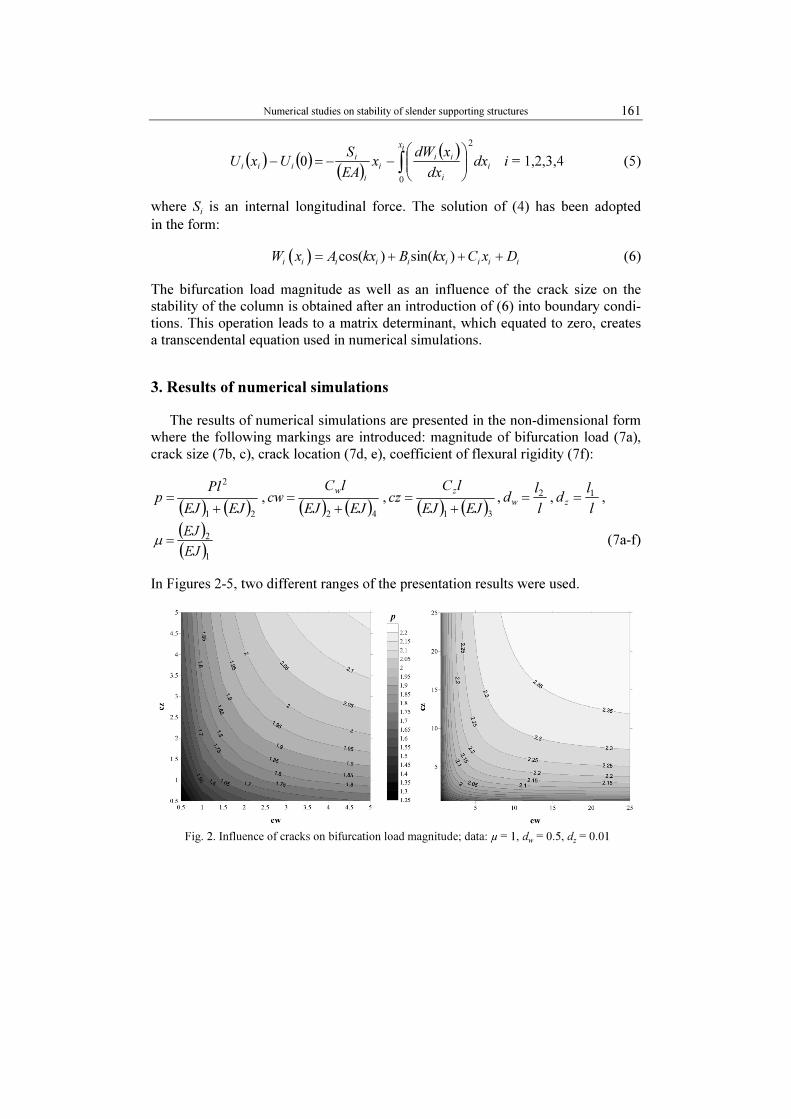
In Figures 2-5, two different ranges of the presentation results were used.
Fig. 2. Influence of cracks on bifurcation load magnitude; data: µ = 1, d
w = 0.5, d
z = 0.01

K. Sokół, S. Uzny 162
Fig. 3. Influence of the cracks on bifurcation load magnitude; data: µ = 1, d
w = d
z = 0.5
Fig. 4. Influence of the cracks on bifurcation load magnitude; data: µ = 1, d
w = 0.5, d
z = 0.75
Fig. 5. Influence of the cracks on bifurcation load magnitude; data: µ = 1, d
w = 0.5, d
z = 0.99
Numerical studies on stability of slender supporting structures 163
The parameters p, cw, cz are related to the total stiffness of the system. This type
of substitution is widely used in the presentation of the results and gives a great
comparison opportunity of the systems loaded by the same type of an external force
but at different parameters of the structure in which the crack is present. In the
simulations it is assumed that: ( ) ( ) ( ) ( )4231
, EJEJEJEJ == .
Because of a large number of results and different configurations, for the general
presentation and description the following locations of cracks have been chosen:
dw = 0.5 and d
z = 0.01, 0.5, 0,75, 0.99. Additionally considered crack sizes are
0.1 < cw < 100, 0.1 < cz < 100 and µ = 0.2, 0.5, 1.
Taking into account the results from Figure 2, it can be assumed that the lowest
magnitude of bifurcation load at this configuration (p = 1.25) appears at the smallest
stiffness of rotational springs (highest crack size). It must be stated that the lowest
loading capacity is not the lowest one that can be observed (see Fig. 3). The contours
are unsymmetrical due to different locations of the cracks. The greater the rotational
spring stiffness, the higher the loading capacity of the column. The bifurcation
load area, unaffected by cracks can be found at p = π2/4 (at cw > 100, cz >100) -
non-dimensional loading capacity of a cantilever column subjected to Euler’s load.
In Figure 3, the cracks are placed symmetrically at dw = dz = 0.5, which results
in symmetrical data distribution but, what is most important, the loading capacity
decreases with respect to Figure 2, down to p = 1.16 (the lowest loading capacity).
With the appearance of the crack at dz = 0.75 (Fig. 4) an increase of the lowest
loading capacity is present (p = 1.49).
An analysis of Figure 5 shows that the crack presence near the free end of
the column (dz = 0.99) has small influence on bifurcation load magnitude, regard-
less of its size. The lowest bifurcation load magnitude is p = 1.75. It can be
assumed that an increase of the unaffected area results in more a rapid loading
capacity decrease and that the minimum loading capacity decreases at the begin-
ning (crack “shifts” from the fixation in the direction of the free end) and after
reaching the critical point an increase can be observed. The location of the critical
point depends on crack location in the other rod as well as on coefficient of flexural
rigidity.
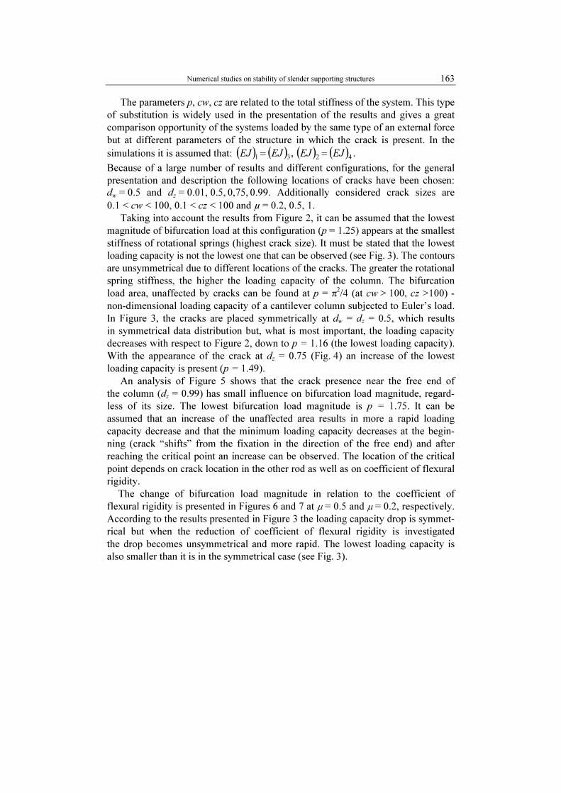
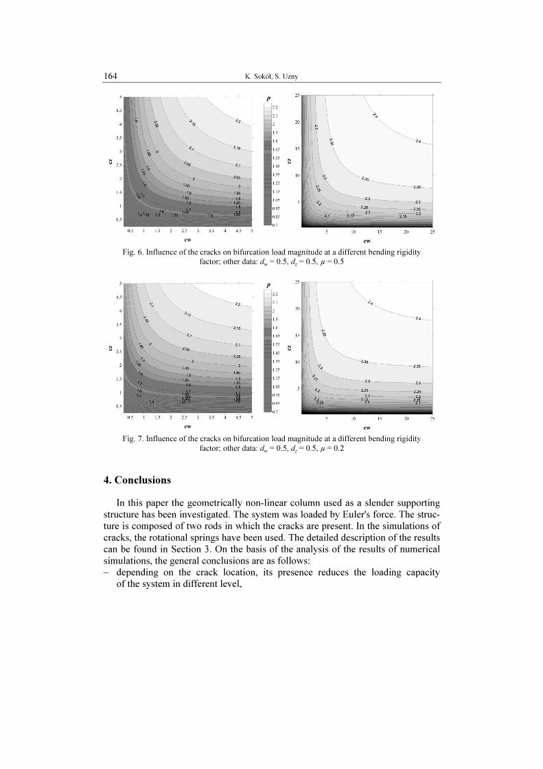
The change of bifurcation load magnitude in relation to the coefficient of
flexural rigidity is presented in Figures 6 and 7 at µ = 0.5 and µ = 0.2, respectively.
According to the results presented in Figure 3 the loading capacity drop is symmet-
rical but when the reduction of coefficient of flexural rigidity is investigated
the drop becomes unsymmetrical and more rapid. The lowest loading capacity is
also smaller than it is in the symmetrical case (see Fig. 3).
K. Sokół, S. Uzny 164
Fig. 6. Influence of the cracks on bifurcation load magnitude at a different bending rigidity
factor; other data: dw = 0.5, d
z = 0.5, µ = 0.5
Fig. 7. Influence of the cracks on bifurcation load magnitude at a different bending rigidity
factor; other data: dw = 0.5, d
z = 0.5, µ = 0.2
4. Conclusions
In this paper the geometrically non-linear column used as a slender supporting
structure has been investigated. The system was loaded by Euler's force. The struc-
ture is composed of two rods in which the cracks are present. In the simulations of
cracks, the rotational springs have been used. The detailed description of the results
can be found in Section 3. On the basis of the analysis of the results of numerical
simulations, the general conclusions are as follows:
– depending on the crack location, its presence reduces the loading capacity
of the system in different level,
Numerical studies on stability of slender supporting structures 165
– the size of unaffected by cracks area (part of the cw - cz graph for which the drop
of loading capacity is smaller than 1%) highly depends on the crack location,
– the value of bifurcation load changes nonlinearly with respect to the location of
the crack,
– the change of loading capacity highly depends on coefficient of flexural rigidity.
When the non-linear systems are investigated, it can be stated that at higher
flexural rigidity asymmetry the defect on the stiffer rod will lead to greater reduc-
tion of bifurcation load magnitude than the defect of the less rigid one while with
small asymmetry, damage to any rod will have a similar influence on load bifurca-
tion. Due to a very complicated problem and a large number of results, the present-
ed plots are only a small sample of data used in structure monitoring. In the future,
the investigations on dynamic characteristics should be discussed and experimental
studies should be done in order to verify the correctness of the proposed mathemat-
ical models.
References
[1] Anifantis N., Dimarogonas A.D., Stability of columns with a single crack subjected to follower
and axial loads, International Journal of Solids and Structures 1999, 19, 281-291.
[2] Chondros T.G., Dimarogonas A.D., Dynamic sensitivity of structures to cracks, Journal of
Vibration, Acoustics, Stress and Reliability in Design 1981, 111, 251-256.
[3] Lee J., Bergman L.A., The vibration of stepped beams and rectangular plates by an elemental
dynamic flexibility method, Journal of Sound and Vibration 1994, 171, 617-640.
[4] Chondros T.G., The continuous crack flexibility model for crack identification, Fatigue & Frac-
ture of Engineering Materials & Structures 2001, 24, 643-650.
[5] Binici B., Vibration of beams with multiple open cracks subjected to axial force, Journal of
Sound and Vibration 2005, 287, 277-295.
[6] Sokół K., Linear and nonlinear vibrations of a column with an internal crack, Journal of Engi-
neering Mechanics 2014, 140(5), http://dx.doi.org/10.1061/(ASCE)EM.1943-7889.0000719
[7] Sokół K., Uzny S., Instability and vibration of multi-member columns subjected to Euler’s load,
Archive of Applied Mechanics 2015, DOI: 10.1007/s00419-015-1068-6.
[8] Sokół K., Kulawik A., Optimization of slender systems by means of genetic algorithms, Journal
of Applied Mathematics and Computational Mechanics 2014, 13(1), 115-125.
[9] Chondros T.G., Dimarogonas A.D., Yao J., A continuous cracked beam vibration theory, Jour-
nal of Sound and Vibration 1998, 215, 17-34.
[10] Arif Gurel M., Buckling of slender prismatic circular columns weakened by multiple edge
cracks, Acta Mechanica 2007, 188, 1-19.
[11] Tomski L., Uzny S., Vibration and stability of geometrically non-linear column subjected to
generalised load by a force directed towards the positive pole, International Journal of Structural
Stability and Dynamics 2008, 8(1), 1-24.
[12] Tomski L., Uzny S., Free vibration and the stability of a geometrically non-linear column loaded by a follower force directed towards the positive pole, International Journal of Solids and Struc-
tures 2008, 45(1), 87-112.