Numerical simulation of process dynamics during laser · PDF fileAppl Phys A DOI...
7
Appl Phys A DOI 10.1007/s00339-011-6702-8 Numerical simulation of process dynamics during laser beam drilling with short pulses Karl-Heinz Leitz · Holger Koch · Andreas Otto · Michael Schmidt Received: 26 October 2011 / Accepted: 15 November 2011 © Springer-Verlag 2011 Abstract In the last years, laser beam drilling became in- creasingly important for many technical applications as it allows the contactless production of high quality drill holes. So far, mainly short laser pulses are of industrial relevance, as they offer a good compromise between precision and ef- ficiency and combine high ablation efficiency with low ther- mal damage of the workpiece. Laser beam drilling in this pulse length range is still a highly thermal process. There are two ablation mechanisms: evaporation and melt expulsion. In order to achieve high quality processing results, a basic process understanding is absolutely necessary. Yet, process observations in laser beam drilling suffer from both the short time scales and the restricted accessibility of the interaction zone. Numerical simulations offer the possibility to acquire additional knowledge of the process as they allow a direct look into the drill hole during the ablation process. In this contribution, a numerical finite volume multi-phase simu- lation model for laser beam drilling with short laser pulses shall be presented. The model is applied for a basic study of the ablation process with μs and ns laser pulses. The ob- tained results show good qualitative correspondence with experimental data. K.-H. Leitz ( ) · H. Koch · M. Schmidt Chair of Photonic Technologies and Erlangen Graduate School in Advanced Optical Technologies (SAOT), University of Erlangen–Nuremberg, Paul-Gordan-Str. 3, 91052 Erlangen, Germany e-mail: [email protected] A. Otto Institute for Production Engineering and Laser Technology, Vienna University of Technology, Gusshausstrasse 30, 1040 Vienna, Austria 1 Introduction Generally, the quality of laser drilled holes gets better with shorter pulse length, mainly due to the reduced formation of melt. However, efficiency decreases as well (see Fig. 1). Single pulse drilling using ms and μs pulses allows the pro- duction of many holes within a short time. As there is quite a big amount of melt involved in the process, the quality and reproducibility of the holes is rather low. If higher pre- cision is needed, short and ultrashort pulses in combination with adequate drilling strategies are applied. In this pulse length range, only a small amount of melt is involved in the process, which means that high accuracy can be achieved. However, in the past the medium laser powers of ultrashort- pulsed systems were not sufficient to fulfil industrial effi- ciency requirements. Besides, studies have shown that even with ultrashort pulses the generation of melt cannot be pre- vented completely [1–7]. Only recently first attempts for the application of ultrashort laser pulses in industrial produc- tion have been reported [8, 9]. However, so far in many in- dustrial applications Q-switched laser systems in the micro- and nanosecond range are still widely common because they can deliver high medium laser power and allow a good com- promise between precision and efficiency. As in these pro- cesses, there is still a certain amount of melt involved, the choice of the right process parameters and the most suitable drilling strategy is of extreme importance in order to achieve the requested quality [10]. When a laser pulse hits the material, within a short time a multitude of highly dynamic coupled physical processes take place (see Fig. 2). The laser beam is absorbed on the surface of the material, and due to the high intensities of pulsed laser radiation, nearly instantly surface temperatures of some thousand Kelvin are reached, leading to an abrupt evaporation, ionisation of the material and the occurrence of
Transcript of Numerical simulation of process dynamics during laser · PDF fileAppl Phys A DOI...

Appl Phys ADOI 10.1007/s00339-011-6702-8
Numerical simulation of process dynamics during laser beamdrilling with short pulses
Karl-Heinz Leitz · Holger Koch · Andreas Otto ·Michael Schmidt
Received: 26 October 2011 / Accepted: 15 November 2011© Springer-Verlag 2011
Abstract In the last years, laser beam drilling became in-creasingly important for many technical applications as itallows the contactless production of high quality drill holes.So far, mainly short laser pulses are of industrial relevance,as they offer a good compromise between precision and ef-ficiency and combine high ablation efficiency with low ther-mal damage of the workpiece. Laser beam drilling in thispulse length range is still a highly thermal process. There aretwo ablation mechanisms: evaporation and melt expulsion.In order to achieve high quality processing results, a basicprocess understanding is absolutely necessary. Yet, processobservations in laser beam drilling suffer from both the shorttime scales and the restricted accessibility of the interactionzone. Numerical simulations offer the possibility to acquireadditional knowledge of the process as they allow a directlook into the drill hole during the ablation process. In thiscontribution, a numerical finite volume multi-phase simu-lation model for laser beam drilling with short laser pulsesshall be presented. The model is applied for a basic study ofthe ablation process with µs and ns laser pulses. The ob-tained results show good qualitative correspondence withexperimental data.
K.-H. Leitz (�) · H. Koch · M. SchmidtChair of Photonic Technologies and Erlangen Graduate School inAdvanced Optical Technologies (SAOT), University ofErlangen–Nuremberg, Paul-Gordan-Str. 3, 91052 Erlangen,Germanye-mail: [email protected]
A. OttoInstitute for Production Engineering and Laser Technology,Vienna University of Technology, Gusshausstrasse 30,1040 Vienna, Austria
1 Introduction
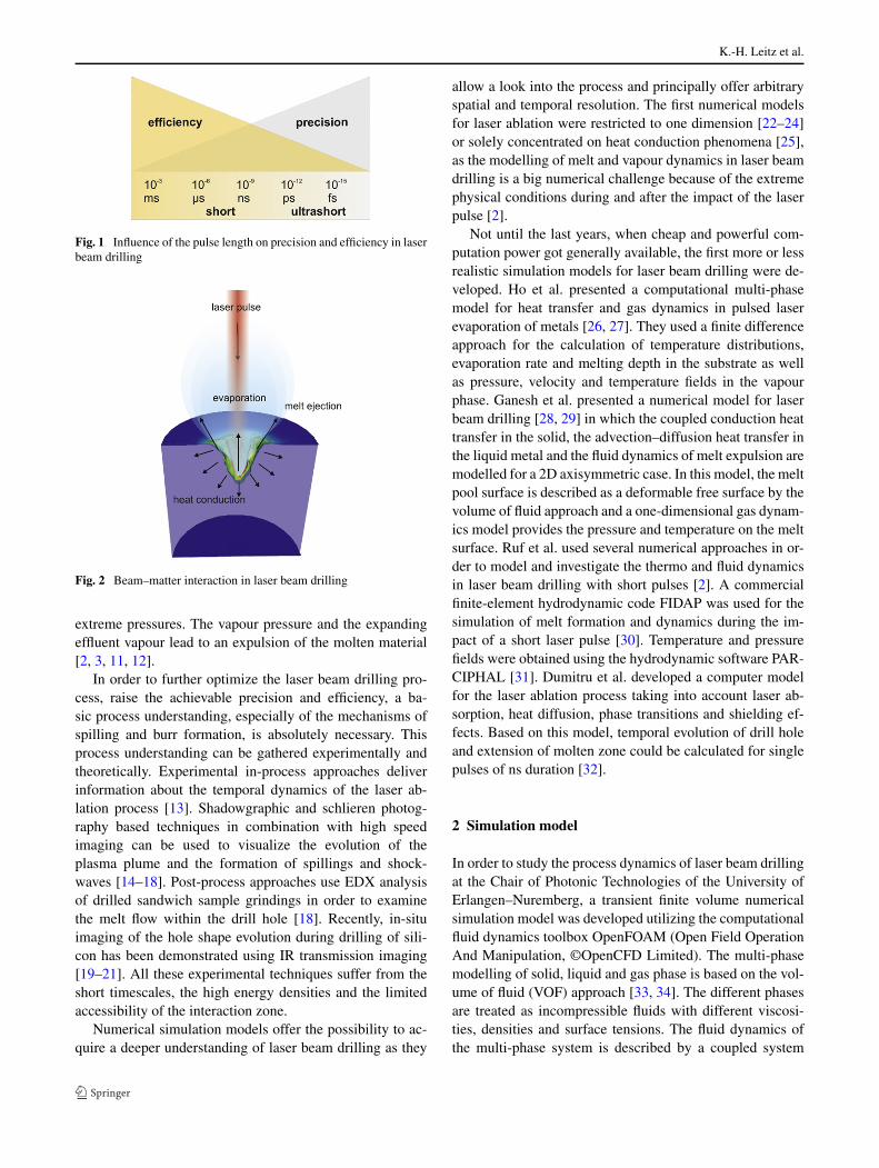
Generally, the quality of laser drilled holes gets better withshorter pulse length, mainly due to the reduced formationof melt. However, efficiency decreases as well (see Fig. 1).Single pulse drilling using ms and µs pulses allows the pro-duction of many holes within a short time. As there is quitea big amount of melt involved in the process, the qualityand reproducibility of the holes is rather low. If higher pre-cision is needed, short and ultrashort pulses in combinationwith adequate drilling strategies are applied. In this pulselength range, only a small amount of melt is involved in theprocess, which means that high accuracy can be achieved.However, in the past the medium laser powers of ultrashort-pulsed systems were not sufficient to fulfil industrial effi-ciency requirements. Besides, studies have shown that evenwith ultrashort pulses the generation of melt cannot be pre-vented completely [1–7]. Only recently first attempts for theapplication of ultrashort laser pulses in industrial produc-tion have been reported [8, 9]. However, so far in many in-dustrial applications Q-switched laser systems in the micro-and nanosecond range are still widely common because theycan deliver high medium laser power and allow a good com-promise between precision and efficiency. As in these pro-cesses, there is still a certain amount of melt involved, thechoice of the right process parameters and the most suitabledrilling strategy is of extreme importance in order to achievethe requested quality [10].
When a laser pulse hits the material, within a short timea multitude of highly dynamic coupled physical processestake place (see Fig. 2). The laser beam is absorbed on thesurface of the material, and due to the high intensities ofpulsed laser radiation, nearly instantly surface temperaturesof some thousand Kelvin are reached, leading to an abruptevaporation, ionisation of the material and the occurrence of
K.-H. Leitz et al.
Fig. 1 Influence of the pulse length on precision and efficiency in laserbeam drilling
Fig. 2 Beam–matter interaction in laser beam drilling
extreme pressures. The vapour pressure and the expandingeffluent vapour lead to an expulsion of the molten material[2, 3, 11, 12].
In order to further optimize the laser beam drilling pro-cess, raise the achievable precision and efficiency, a ba-sic process understanding, especially of the mechanisms ofspilling and burr formation, is absolutely necessary. Thisprocess understanding can be gathered experimentally andtheoretically. Experimental in-process approaches deliverinformation about the temporal dynamics of the laser ab-lation process [13]. Shadowgraphic and schlieren photog-raphy based techniques in combination with high speedimaging can be used to visualize the evolution of theplasma plume and the formation of spillings and shock-waves [14–18]. Post-process approaches use EDX analysisof drilled sandwich sample grindings in order to examinethe melt flow within the drill hole [18]. Recently, in-situimaging of the hole shape evolution during drilling of sili-con has been demonstrated using IR transmission imaging[19–21]. All these experimental techniques suffer from theshort timescales, the high energy densities and the limitedaccessibility of the interaction zone.
Numerical simulation models offer the possibility to ac-quire a deeper understanding of laser beam drilling as they
allow a look into the process and principally offer arbitraryspatial and temporal resolution. The first numerical modelsfor laser ablation were restricted to one dimension [22–24]or solely concentrated on heat conduction phenomena [25],as the modelling of melt and vapour dynamics in laser beamdrilling is a big numerical challenge because of the extremephysical conditions during and after the impact of the laserpulse [2].
Not until the last years, when cheap and powerful com-putation power got generally available, the first more or lessrealistic simulation models for laser beam drilling were de-veloped. Ho et al. presented a computational multi-phasemodel for heat transfer and gas dynamics in pulsed laserevaporation of metals [26, 27]. They used a finite differenceapproach for the calculation of temperature distributions,evaporation rate and melting depth in the substrate as wellas pressure, velocity and temperature fields in the vapourphase. Ganesh et al. presented a numerical model for laserbeam drilling [28, 29] in which the coupled conduction heattransfer in the solid, the advection–diffusion heat transfer inthe liquid metal and the fluid dynamics of melt expulsion aremodelled for a 2D axisymmetric case. In this model, the meltpool surface is described as a deformable free surface by thevolume of fluid approach and a one-dimensional gas dynam-ics model provides the pressure and temperature on the meltsurface. Ruf et al. used several numerical approaches in or-der to model and investigate the thermo and fluid dynamicsin laser beam drilling with short pulses [2]. A commercialfinite-element hydrodynamic code FIDAP was used for thesimulation of melt formation and dynamics during the im-pact of a short laser pulse [30]. Temperature and pressurefields were obtained using the hydrodynamic software PAR-CIPHAL [31]. Dumitru et al. developed a computer modelfor the laser ablation process taking into account laser ab-sorption, heat diffusion, phase transitions and shielding ef-fects. Based on this model, temporal evolution of drill holeand extension of molten zone could be calculated for singlepulses of ns duration [32].
2 Simulation model
In order to study the process dynamics of laser beam drillingat the Chair of Photonic Technologies of the University ofErlangen–Nuremberg, a transient finite volume numericalsimulation model was developed utilizing the computationalfluid dynamics toolbox OpenFOAM (Open Field OperationAnd Manipulation, ©OpenCFD Limited). The multi-phasemodelling of solid, liquid and gas phase is based on the vol-ume of fluid (VOF) approach [33, 34]. The different phasesare treated as incompressible fluids with different viscosi-ties, densities and surface tensions. The fluid dynamics ofthe multi-phase system is described by a coupled system

Numerical simulation of process dynamics during laser beam drilling with short pulses
Fig. 3 Adaptive meshing
of three differential transport equations [34–36]. Firstly, onehas the continuity equation
∂ρ
∂t+ ∇ · u = 0 (1)
corresponding to the conservation of mass, which states thatthe mass of a fluid of density ρ can only be changed bya flow with velocity u across the boundaries. It is closelyrelated to the phase transport equation
∂α
∂t+ ∇ · αu = 0 (2)
with the phase indicator function α whereby ρ = ∑i αiρi .
The second equation is the incompressible Navier–Stokesequation
ρ∂u∂t
+ ρu · ∇u = −∇p + ρg + fσ + μ∇2u (3)
with the dynamic viscosity μ, the pressure p, the gravityconstant g and the surface tension fσ , which corresponds tothe conservation of impulse and describes the fluid dynamicsof the multi-phase system.
The description of the thermal effects during the processis based on the third equation, the equation of heat conduc-tion. As the enthalpies of melting and evaporation play asignificant role in the energy balance, they have to be con-sidered. Therefore, an energy-based formulation of the heatconduction equation was chosen taking into account the en-thalpies of melting and evaporation [37]:
∂
∂t(ρH) + ∇ · (ρuH) = ∇ · (λ∇T ) + Q. (4)
It includes a convection, conduction and a source term Q
describing the energy input of the laser. The equation of heatconduction describes the formation of the temperature fieldT and corresponds to the conservation of energy [35].
In order to reduce computation time, a symmetry planewas introduced in the model. Furthermore, adaptive mesh-ing was implemented in OpenFOAM. Hereby all cells con-taining a fraction of melt or vapour different to zero werelocally refined. Figure 3 shows the adaptive mesh used forthe simulation.
Table 1 Process parameters
Parameter Symbol Unit Value
Medium laser power P W 500
Laser wavelength λ nm 1064
Pulse frequency f s−1 10000
Pulse length τ s 10−6/10−9
Pulse energy ε J 0.05
Focus radius r µm 50
Sheet thickness d mm 0.5
3 Simulation results
The numerical simulation model for beam–matter interac-tion in laser material processing described in the previousparagraph was applied in order to study the process dynam-ics of laser beam drilling with short pulses. For this purpose,percussion drilling processes of a 0.5 mm steel sheets weresimulated. Hereby pulse durations of 1 µs and 1 ns with iden-tical laser pulse energies were compared to each other. Bothspatial and temporal shape of the pulses were of Gaussianshape. Except the pulse duration the other process parame-ters were exactly the same. They are listed in Table 1.
Figure 4 shows the obtained simulation results for theevolution of the drill hole after 1, 2, 3, 5 and 10 laser pulsesof µs and ns duration. The pictures are taken 5 µs after theimpact of the laser pulse. Figures 5–10 show the temporalevolution of the drill hole during the first, fifth and tenthlaser pulse. The respective time steps were chosen exem-plarily in order to show the different phases of the ablationprocess. The pictures show the interfaces between the solid,liquid and gas phase. The colour corresponds the respec-tive temperature. Vapour material is visualized in transpar-ent white in the gaseous phase.
A comparison of the different pulse durations shows thatin an early stage the drilling efficiency of µs pulses is higher,as the energy is used more efficiently. Whereas for ns pulsesnearly the complete material is evaporated, for µs pulses theexpulsion of molten material significantly contributes theablation process leading to effective higher ablation rates.In the first phase of the drilling process, ns pulses allow anearly melt-free ablation, whereas µs pulses lead to a signif-icant melting zone. In a later phase of the drilling process,however, the ablation efficiency of µs pulses decreases as ef-ficiency of melt expulsion drops with increasing depth of thedrill hole, whereas it nearly stays constant for ns pulses asthe vapour material can still leave deeper drill holes.
This effect can also be observed experimentally. Whereasfor µs pulses the increase of drilling depth significantly de-creases with the number of laser pulses, ablation efficiencynearly stays constant for ns pulses (see Fig. 11). For deeperholes also for ns pulses a certain amount of melt is involved.

K.-H. Leitz et al.
Fig. 4 Drill hole evolution after different numbers of µs and ns laserpulses. The pictures are taken respectively 5 µs after the impact of thelaser pulse
Fig. 5 Drill hole evolution after the first µs laser pulse (t time rela-tive to laser pulse)
Fig. 6 Drill hole evolution after the fifth µs laser pulse (t time rela-tive to laser pulse)
Fig. 7 Drill hole evolution after the tenth µs laser pulse (t time rel-ative to laser pulse)
Fig. 8 Drill hole evolution after the first ns laser pulse (t time rela-tive to laser pulse)
Fig. 9 Drill hole evolution after the fifth ns laser pulse (t time rela-tive to laser pulse)

Numerical simulation of process dynamics during laser beam drilling with short pulses
Fig. 10 Drill hole evolution after the tenth ns laser pulse (t timerelative to laser pulse)
Fig. 11 Grindings of drill holes after different numbers of µs (pulseduration τ = 100 s, wavelength λ = 1064 nm, pulse energy ε = 0.06 J,pulse frequency f ≈ 1 Hz (hand-trigger)) and ns (pulse durationτ = 15 ns, wavelength λ = 1064 nm, pulse energy ε = 0.001 J, pulsefrequency f = 100 Hz) drill holes after different numbers of laserpulses
The efficiency of the energy removal drops as the vapour canno longer leave as freely as in an early stage of the drillingprocess. As a consequence this leads to an enhanced depo-
Fig. 12 High speed image series of the impact of a µs laser pulse(pulse duration τ = 200 s, wavelength λ = 1064 nm, pulse energyε = 0.6 J). Spillings are indicated with dashed lines
sition of energy in the drill hole and a subsequent surfacemelting. Furthermore, with increasing depth of the drill holethe laser pulse hits a bigger area leading to a decreased ef-fective laser intensity.
For both µs and ns pulses, a slight burr formation as wellas the formation of spillings can be observed. Both of theseeffects are more pronounced for µs pulses.
A more detailed look at the temporal dynamics of theprocess clearly shows the difference between µs and ns laserpulses. Due to the shorter interaction time, there is no vapour1 µs after the ns pulses whereas for the µs pulse it is stillpresent. Besides µs pulse ablation is accompanied by meltformation and a subsequent thermal influence of the work-piece material (compare Figs. 5 and 8).
In a later phase of the percussion drilling process, othereffects become obvious (see Figs. 6 and 9). In this phase,the main ablation mechanism for µs pulses still is evapora-
K.-H. Leitz et al.
tion, although there is quite a big amount of melt involvedin the process. Part of the material stays molten for up to100 µs without leaving the drill hole, leading to a significantthermal influence of the workpiece. Furthermore, the simu-lation shows that evaporation does not stop after the impactof the laser pulse. Due to the huge amount of energy con-tained in the melt and vapour in the drill hole, evaporationgoes on more than 20 µs after the actual impact of the laserpulse. The energy stored in the overheated material leads toan elongated evaporation process (see Fig. 6). For ns pulsesthe situation is different. The vapour material is immediatelytransported away, leading to a low thermal influence of theworkpiece. Besides the simulation shows that in this drillingphase also for ns pulses a small amount of melt occurs. Yet,the melt has vanished after 20 µs (see Fig. 9). This is inaccordance with experimental observations presented in thenext section which show that µs pulses lead to a much morepronounced heat affected zone than ns pulses (see Fig. 11).
In a later phase of the drilling process, for µs pulses notall of the molten material resolidifies again. Figure 7 showsthe drill hole before the impact of the tenth laser pulse, 98 µsafter the impact of the previous. The drill hole is nearly com-pletely filled with melt, showing an enclosed bubble of gas.Observations of similar enclosures were made in grindingsof µs pulse series (see Fig. 11). The subsequent impact ofthe µs laser pulse leads to the expulsion of melt and the for-mation of spillings. Obviously, in this process phase meltexpulsion is a relevant ablation mechanism for µs pulses.The spilling after the tenth µs laser pulse (see Fig. 7) showsa longish shape. Spillings of similar shape were observed inhigh speed imaging of a µs drilling process (see Fig. 12).
In this later process phase also for ns pulses, a significantamount of melt and spillings can be observed (see Fig. 10).Yet, compared to µs pulses the process is much less thermal.The amount of melt as well as of spillings is much smaller.
4 Experimental evaluation
In order to evaluate the numerical simulation model for laserbeam drilling, basic experiments with µs and ns laser pulseswere performed. For this purpose, steel sheets of 0.5 mmwere irradiated with different numbers of µs and ns laserpulses.
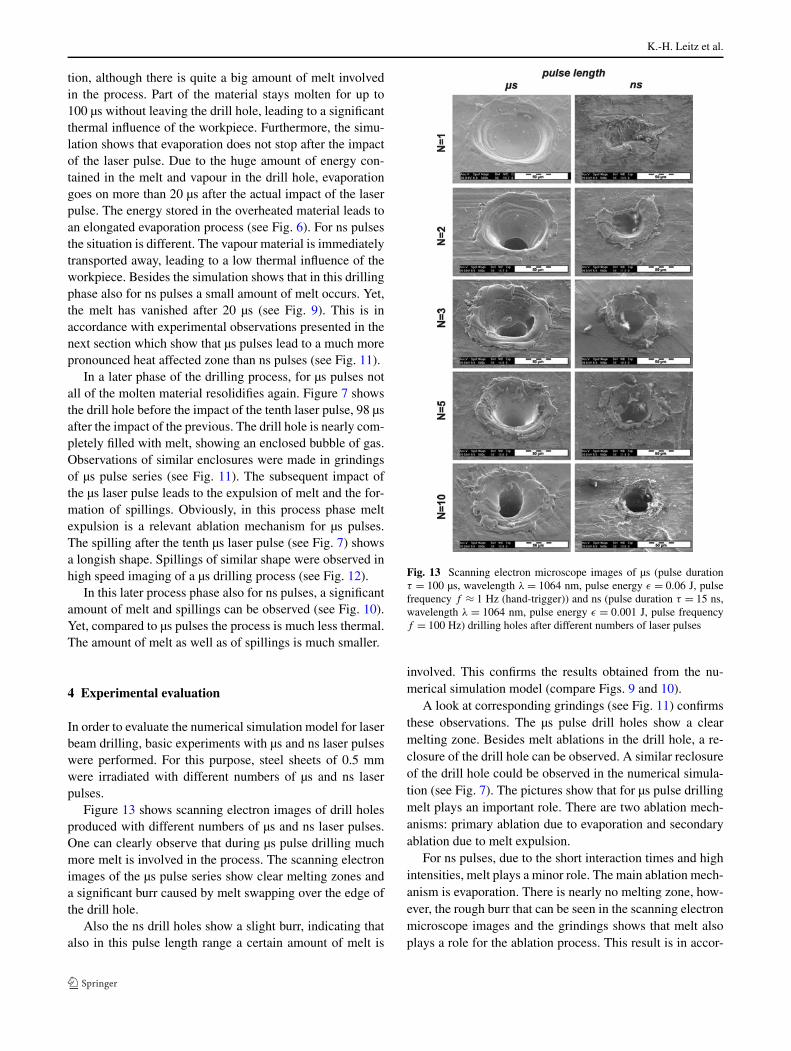
Figure 13 shows scanning electron images of drill holesproduced with different numbers of µs and ns laser pulses.One can clearly observe that during µs pulse drilling muchmore melt is involved in the process. The scanning electronimages of the µs pulse series show clear melting zones anda significant burr caused by melt swapping over the edge ofthe drill hole.
Also the ns drill holes show a slight burr, indicating thatalso in this pulse length range a certain amount of melt is
Fig. 13 Scanning electron microscope images of µs (pulse durationτ = 100 µs, wavelength λ = 1064 nm, pulse energy ε = 0.06 J, pulsefrequency f ≈ 1 Hz (hand-trigger)) and ns (pulse duration τ = 15 ns,wavelength λ = 1064 nm, pulse energy ε = 0.001 J, pulse frequencyf = 100 Hz) drilling holes after different numbers of laser pulses
involved. This confirms the results obtained from the nu-merical simulation model (compare Figs. 9 and 10).
A look at corresponding grindings (see Fig. 11) confirmsthese observations. The µs pulse drill holes show a clearmelting zone. Besides melt ablations in the drill hole, a re-closure of the drill hole can be observed. A similar reclosureof the drill hole could be observed in the numerical simula-tion (see Fig. 7). The pictures show that for µs pulse drillingmelt plays an important role. There are two ablation mech-anisms: primary ablation due to evaporation and secondaryablation due to melt expulsion.
For ns pulses, due to the short interaction times and highintensities, melt plays a minor role. The main ablation mech-anism is evaporation. There is nearly no melting zone, how-ever, the rough burr that can be seen in the scanning electronmicroscope images and the grindings shows that melt alsoplays a role for the ablation process. This result is in accor-

Numerical simulation of process dynamics during laser beam drilling with short pulses
dance with the result obtained from the numerical simula-tion (compare Figs. 9 and 10).
In order to further investigate the dynamics of short pulselaser drilling, a high speed camera system with a frame rateof 10 kHz and a pulsed diode laser illumination was used tomonitor a drilling process with laser pulses of 200 µs (seeFig. 12). Immediately after the impact of the laser pulse,spillings in two different directions occur. Spillings of simi-lar longish shape were also observed in the numerical simu-lations (see Fig. 7).
5 Conclusions
In this contribution, a numerical simulation model for laserbeam drilling with short laser pulses of µs and ns durationwas presented. It is able to describe the dynamics of the laserbeam drilling process and allows a look into the drill holewith high spatial and temporal resolution. It realistically de-scribes the process of laser ablation with µs and ns pulsesby evaporation and melt expulsion. The obtained simulationresults show good qualitative correspondence with experi-mental observations obtained from scanning electron micro-scope images, metallurgical grindings and high speed imag-ing.
The model shows that depending on pulse duration andphase of the drilling process different ablation mechanismsare dominant. Depending on the requirements with respectto quality and efficiency, the model can help identify themost suitable beam source and drilling strategy for the re-spective application.
Acknowledgements The authors gratefully acknowledge funding ofthe project “Gezielte lokale Sub-100-nm-Strukturierung durch ultra-kurze Laserpulse mithilfe von mit einer optischen Pinzette position-ierten Kolloiden unter Ausnutzung von Nahfeldeffekten” within theDFG priority programme 1327 “Optisch erzeugte Sub-100-nm Struk-turen für biomedizinische und technische Applikationen” and the fund-ing of the Erlangen Graduate School in Advanced Optical Technolo-gies (SAOT) by the German National Science Foundation (DFG) inthe framework of the excellence initiative.
References
1. S. Preuss, E. Matthias, M. Stuke, Appl. Phys. A 59 (1994)2. A. Ruf, Modellierung des Perkussionsbohrens von Metallen mit
kurz- und ultrakurz gepulsten Lasern (Herbert Utz Verlag, Mu-nich, 2004)
3. F. Dausinger, LTJ Nr. 1 (2004)
4. D. Breitling, A. Ruf, F. Dausinger, Proc. SPIE 5339 (2005)5. C.Y. Chien, M.C. Gupta, Appl. Phys. A 81 (2005)6. A. Michalowski, D. Walter, F. Dausinger, J. Laser Micro Nanoeng.
3(3) (2008)7. T. Lehecka, A. Mostovych, J. Thomas, Appl. Phys. A 92 (2008)8. T. Bauer, J. Radtke, J. König, in Proceedings of the LAMP 2009
(2009)9. J. König, T. Bauer, Proc. SPIE 7925 (2011)
10. S. Preuss, A. Demchuk, M. Stuke, Appl. Phys. A 61 (1995)11. M. Dirscherl, Ultrakurzpulslaser—Grundlagen und Anwendungen
(Bayerisches Laserzentrum, Erlangen, 2005)12. K.-H. Leitz, H. Koch, A. Otto, M. Schmidt, in Proceedings of the
LIM 2009 (2009)13. S. Preuss, M. Späth, Y. Zhang, M. Stuke, Appl. Phys. Lett 62(23)
(1993)14. A. Schoonderbeek, C.A. Biesheuvel, R.M. Hofstra, K.-J. Boller,
J. Meijer, Appl. Phys. A 80 (2005)15. A. Michalowski, D. Walter, P. Berger, F. Dausinger, in Proceed-
ings of the LIM 2007 (2007)16. D. Walter, A. Michalowski, R. Gauch, F. Dausinger, in Proceed-
ings of the LIM 2007 (2007)17. S. Amoruso, R. Bruzesse, C. Pagano, X. Wang, Appl. Phys. A 89
(2007)18. A. Michalowski, R. Weber, R. Graf, in Proceedings of the LIM
2009 (2009)19. S. Döring, S. Richter, S. Nolte, A. Tünnermann, Opt. Express
19(18) (2010)20. S. Döring, S. Richter, S. Nolte, A. Tünnermann, Proc. SPIE 7920
(2011)21. S. Döring, S. Richter, A. Tünnermann, S. Nolte, Appl. Phys. A
105 (2011)22. R.G. Evans, A.R. Bell, B.J. MacGowan, J. Phys. D., Appl. Phys.
15 (1982)23. C.L. Chan, J. Mazumder, J. Appl. Phys. 62(11) (1987)24. C.D. Boley, in International Conference on Applications of Lasers
in Electro-Optics (1994)25. M.F. Modest, Int. J. Heat Mass Transf. 39(2) (1996)26. J.R. Ho, C.P. Grigoropoulos, J.A.C. Humphrey, J. Appl. Phys.
78(7) (1995)27. J.R. Ho, C.P. Grigoropoulos, J.A.C. Humphrey, J. Appl. Phys.
79(9) (1996)28. R.K. Ganesh, W.W. Bowley, R.R. Bellantone, H. Yukap, J. Com-
put. Phys. 125 (1996)29. R.K. Ganesh, A. Faghri, Y. Hahn, Int. J. Heat Mass Transf. 40(14)
(1997)30. A. Ruf, D. Breitling, P. Berger, F. Dausinger, H. Hügel, Proc. SPIE
4830 (2003)31. A. Ruf, F. Berger, F. Dausinger, H. Hügel, in Proceedings of the
LIM 2003 (2003)32. G. Dumitru, V. Romano, H.P. Weber, Appl. Phys. A 79 (2004)33. C.W. Hirt, B.D. Nichols, J. Comput. Phys. 39 (1981)34. O. Ubbnik, Numerical prediction of two fluid systems with sharp
interfaces, Ph.D. thesis, University of London, 199735. J.M. Dowden, The Mathematics of Thermal Modeling (Chapman
& Hall/CRC, Boca Raton, 2001)36. M.O. Bristeau, R. Glowinski, J. Priaux, Comput. Phys. Rep. 6
(1987)37. J.M. Dowden, The Theory of Laser Material Processing (Springer,
Berlin, 2009)