Numerical simulation of a pectoral fin during labriform ... · for locomotion. To date, about 20...
10
2038 INTRODUCTION Fishes rely upon different fluid–structure interaction mechanisms for locomotion. To date, about 20 locomotion modes have been identified in steady swimming (Webb, 1994). This diversity comes from different combinations of undulation of flexible bodies and unsteady flapping of body-attached fins. Morphologically, fish fins fall into two categories: median fins (e.g. dorsal fins, ventral fins and caudal fins) and paired fins (e.g. pectoral fins and pelvic fins). Paired fins are employed mostly in motion stabilization, maneuvering and braking, as well as labriform swimming (Webb, 1973; Blake, 1979; Vogel, 1994; Standen, 2008). Indeed, in many species (e.g. teleosts), pectoral fins are often the primary locomotion devices (Videler, 1993). Fish fins are highly mobile, collapsible and capable of changing their effective areas. A pectoral fin consists of a pectoral girdle skeleton, an arrow of four radials that forms a basal support for the fin, a fibrocartilage pad upon which the rays can rotate, a series of fin rays with rotational bases, and muscles that enable movements of the fin rays. Structurally, it forms a skeleton-reinforced membrane system – a soft (and thin) collagenous membrane strengthened by bony fin rays. The Young’s modulus (E) of the fin rays is much larger than that of the membrane so that the bending stiffness of the fin is much higher in the direction of the embedded rays compared with those in other directions (Lauder et al., 2006; Lauder and Madden, 2007). The non-uniform distribution of these rays imparts anisotropic structural flexibility such that certain deformations may be more easily attainable while others are restricted. In many fishes, the first two rays near the leading edge strongly bond together along their length through connective tissues to form a strengthened leading edge (Videler, 1993). This characteristic will later be shown to have an important effect upon the propulsive performance of the fin. The ray fin architecture enables multi-degree-of-freedom control over the motion and deformation of the fins. The basal end of each ray attaches to four separate muscles so that its rotational motion can be actuated individually (i.e. independent of the motions of other rays). In addition, through embedded tendons and a bi-laminar structure of each ray, the fish can actively change the curvature along a ray. According to morphological studies (Harder, 1975; Kardong, 1998), a fin ray contains a central bundle of collagen surrounded by small segmented bony elements called hemitrichs. These elements are paired and resemble a bimetallic strip with two elongated bony elements separated by the central collagen core. A hemitrich is connected with short ligaments and elastic fibers. Through such structures, bending moments can be created along the length of a ray. Kinematically, among fishes capable of sustained pectoral fin propulsion in high speeds, labriform swimming is a combination of an up-and-down (dorsoventral) flapping motion, a back-and-forth (anteroposterior) rowing motion, as well as a pitching motion of the baseline formed by the basal ends of the rays (e.g. Drucker et al., 2006). Although, in certain cases, a fish may perform pure flapping motion (which is also called ‘lift-based’ swimming) or pure rowing motion (‘drag-based’ swimming) (Blake, 1983; Vogel, 1994), in general fish rarely exhibit pure rowing or flapping movements. Instead, in most cases, a combination of them is applied. Owing to the highly flexible membrane and the fin rays, as well as the hydrodynamic interactions of the fins with the surrounding water, pectoral fin motions are usually complicated (Gibb et al., 1994; Lauder and Jayne, 1996). The propulsion performance of pectoral fins is affected by various factors, including, for example, the geometry of the fin, the length and flexibility of the embedded rays, as well as the amplitude, orientation and phase of each ray during locomotion. In some fishes (e.g. trout), the baseline of the fin undergoes significant pitching The Journal of Experimental Biology 213, 2038-2047 © 2010. Published by The Company of Biologists Ltd doi:10.1242/jeb.040162 Numerical simulation of a pectoral fin during labriform swimming Kourosh Shoele and Qiang Zhu* Department of Structural Engineering, University of California, San Diego, La Jolla, CA 92093, USA *Author for correspondence ([email protected]) Accepted 21 February 2010 SUMMARY We numerically examine the fluid–structure interaction and force generation of a skeleton-reinforced fin that geometrically, structurally and kinematically resembles the pectoral fin of a fish during labriform swimming. This fin contains a soft membrane with negligible bending stiffness and 12 embedded rays (modeled as beams). A potential flow-based boundary element model is applied to solve the fluid flow around the fin, in which the vorticity field is modeled as thin vorticity sheets shed from prescribed locations (the sharp trailing edge). The fin motion is actuated by dorsoventral and anteroposterior rotations of the rays (the motion of each ray is controlled individually), as well as pitching motion of the baseline. Consequently, the fin undergoes a combination of flapping (lift-based) and rowing (drag-based) motions typical in labriform swimming. The fin motion contains two strokes: a recovery stroke and a power stroke. The performance of the fin depends upon kinematic parameters such as the Strouhal number, the phase lag between rays, the pitching motion of the baseline and the passive deformations of the rays. The most interesting finding is that the strengthening of the ray at the leading edge plays a pivotal role in performance enhancement by reducing the effective angle of attack and decreasing the power expenditure during the recovery stroke. Supplementary material available online at http://jeb.biologists.org/cgi/content/full/213/12/2038/DC1 Key words: fluid-structure interaction, skeleton-reinforced membrane, pectoral fin, labriform locomotion. THE JOURNAL OF EXPERIMENTAL BIOLOGY
Transcript of Numerical simulation of a pectoral fin during labriform ... · for locomotion. To date, about 20...
2038
INTRODUCTIONFishes rely upon different fluid–structure interaction mechanismsfor locomotion. To date, about 20 locomotion modes have beenidentified in steady swimming (Webb, 1994). This diversity comesfrom different combinations of undulation of flexible bodies andunsteady flapping of body-attached fins.
Morphologically, fish fins fall into two categories: median fins(e.g. dorsal fins, ventral fins and caudal fins) and paired fins (e.g.pectoral fins and pelvic fins). Paired fins are employed mostly inmotion stabilization, maneuvering and braking, as well as labriformswimming (Webb, 1973; Blake, 1979; Vogel, 1994; Standen,2008). Indeed, in many species (e.g. teleosts), pectoral fins are oftenthe primary locomotion devices (Videler, 1993).
Fish fins are highly mobile, collapsible and capable of changingtheir effective areas. A pectoral fin consists of a pectoral girdleskeleton, an arrow of four radials that forms a basal support for thefin, a fibrocartilage pad upon which the rays can rotate, a series offin rays with rotational bases, and muscles that enable movementsof the fin rays. Structurally, it forms a skeleton-reinforced membranesystem – a soft (and thin) collagenous membrane strengthened bybony fin rays. The Young’s modulus (E) of the fin rays is muchlarger than that of the membrane so that the bending stiffness ofthe fin is much higher in the direction of the embedded rayscompared with those in other directions (Lauder et al., 2006; Lauderand Madden, 2007). The non-uniform distribution of these raysimparts anisotropic structural flexibility such that certaindeformations may be more easily attainable while others arerestricted. In many fishes, the first two rays near the leading edgestrongly bond together along their length through connective tissuesto form a strengthened leading edge (Videler, 1993). Thischaracteristic will later be shown to have an important effect uponthe propulsive performance of the fin.
The ray fin architecture enables multi-degree-of-freedom controlover the motion and deformation of the fins. The basal end of eachray attaches to four separate muscles so that its rotational motioncan be actuated individually (i.e. independent of the motions of otherrays). In addition, through embedded tendons and a bi-laminarstructure of each ray, the fish can actively change the curvature alonga ray. According to morphological studies (Harder, 1975; Kardong,1998), a fin ray contains a central bundle of collagen surroundedby small segmented bony elements called hemitrichs. Theseelements are paired and resemble a bimetallic strip with twoelongated bony elements separated by the central collagen core. Ahemitrich is connected with short ligaments and elastic fibers.Through such structures, bending moments can be created alongthe length of a ray.
Kinematically, among fishes capable of sustained pectoral finpropulsion in high speeds, labriform swimming is a combination ofan up-and-down (dorsoventral) flapping motion, a back-and-forth(anteroposterior) rowing motion, as well as a pitching motion ofthe baseline formed by the basal ends of the rays (e.g. Drucker etal., 2006). Although, in certain cases, a fish may perform pureflapping motion (which is also called ‘lift-based’ swimming) or purerowing motion (‘drag-based’ swimming) (Blake, 1983; Vogel,1994), in general fish rarely exhibit pure rowing or flappingmovements. Instead, in most cases, a combination of them is applied.Owing to the highly flexible membrane and the fin rays, as well asthe hydrodynamic interactions of the fins with the surrounding water,pectoral fin motions are usually complicated (Gibb et al., 1994;Lauder and Jayne, 1996).
The propulsion performance of pectoral fins is affected by variousfactors, including, for example, the geometry of the fin, the lengthand flexibility of the embedded rays, as well as the amplitude,orientation and phase of each ray during locomotion. In some fishes(e.g. trout), the baseline of the fin undergoes significant pitching
The Journal of Experimental Biology 213, 2038-2047© 2010. Published by The Company of Biologists Ltddoi:10.1242/jeb.040162
Numerical simulation of a pectoral fin during labriform swimming
Kourosh Shoele and Qiang Zhu*Department of Structural Engineering, University of California, San Diego, La Jolla, CA 92093, USA
*Author for correspondence ([email protected])
Accepted 21 February 2010
SUMMARYWe numerically examine the fluid–structure interaction and force generation of a skeleton-reinforced fin that geometrically,structurally and kinematically resembles the pectoral fin of a fish during labriform swimming. This fin contains a soft membranewith negligible bending stiffness and 12 embedded rays (modeled as beams). A potential flow-based boundary element model isapplied to solve the fluid flow around the fin, in which the vorticity field is modeled as thin vorticity sheets shed from prescribedlocations (the sharp trailing edge). The fin motion is actuated by dorsoventral and anteroposterior rotations of the rays (themotion of each ray is controlled individually), as well as pitching motion of the baseline. Consequently, the fin undergoes acombination of flapping (lift-based) and rowing (drag-based) motions typical in labriform swimming. The fin motion contains twostrokes: a recovery stroke and a power stroke. The performance of the fin depends upon kinematic parameters such as theStrouhal number, the phase lag between rays, the pitching motion of the baseline and the passive deformations of the rays. Themost interesting finding is that the strengthening of the ray at the leading edge plays a pivotal role in performance enhancementby reducing the effective angle of attack and decreasing the power expenditure during the recovery stroke.
Supplementary material available online at http://jeb.biologists.org/cgi/content/full/213/12/2038/DC1
Key words: fluid-structure interaction, skeleton-reinforced membrane, pectoral fin, labriform locomotion.
THE JOURNAL OF EXPERIMENTAL BIOLOGY
2039Pectoral fin in labriform swimming
motion, which may affect the capacity of force generation. Forexample, in rainbow trout, the baseline of the pectoral fin isconnected with the body through a flexible hinge joint that allowsrotational motion (Drucker and Lauder, 2003).
In the present study, we numerically model the effects ofstructural and kinematic parameters upon the performance of anidealized pectoral fin in labriform swimming. In particular, weconcentrate upon the effects of the frequency of motion, thebaseline rotation, the phase lag between the rays, and the bendingstiffness of the rays. For this purpose, we will solve the involvedfluid–structure interaction problem with a fully coupled model.Special effort is expended on clarifying the possible performance-enhancing effects of strengthened leading edge and the rotationof the baseline. Compared with our previous studies of caudalfin dynamics (Zhu and Shoele, 2008) and pectoral fin dynamicsin pure lift-based locomotion (Shoele and Zhu, 2009), our currentwork possesses the following characteristics: (1) instead ofsimple mediolateral motions (Zhu and Shoele, 2008) ordorsoventral motions (Shoele and Zhu, 2009), herein we considera much more complicated and realistic fin kinematics includinganteroposterior, dorsoventral and baseline pitching motionsenabled by synchronized ray rotations and reorientation of thebaseline; (2) we consider a more realistic fin flexibility in whichthe rays have different stiffness; and (3) the hydrodynamic effectsof both the phase lag between rays and the baseline pitchingmotion are explored.
The rest of the paper is organized as follows. In the next sectionwe define the geometry, structure and kinematics of the simplifiedpectoral fin. This is followed by a brief description of thefluid–structure interaction formulation as well as the numericalapproach. Numerical results, including the force generation andpropulsion efficiency of the fin, and the corresponding flow fields,are then provided. Based upon these results, conclusions aredrawn.
MATERIALS AND METHODSGeometry and internal structure of the idealized fin
The geometry and kinematics of the fin are described within aCartesian coordinate system (x, y, z), where x corresponds to theposterior direction, z is along the dorsoventral axis and y is alongthe mediolateral axis. At its initial configuration, the fin lies withinthe x–z plane.
Pectoral fin shape varies among species as a consequence ofdifferent habitats and different roles in swimming. Instead ofexactly duplicating the geometry and kinematics of the fin of aspecific species (Mittal et al., 2006; Bozkurttas et al., 2009), inthe current investigation we consider an idealized fin withsimplified geometry, internal structure and kinematics.Specifically, we use a trapezoidal shaped fin with small base andlong leading edge to imitate pectoral fins of many species (e.g.Stethojulis trilineata, Abudefuf saxatilis). From the biomimeticpoint of view, simplified designs are also easier to bemanufactured.
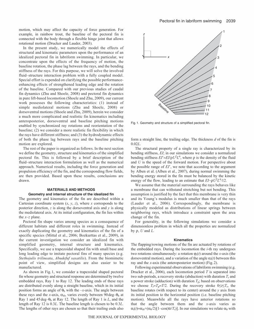
As shown in Fig.1, we consider a trapezoidal shaped pectoralfin whose geometry and structural response are determined by twelveembedded rays, Ray 1 to Ray 12. The leading ends of these raysare distributed evenly along a straight baseline, which in its initialposition forms an angle of b with the –x-axis. The angle betweenthese rays and the x-axis, i0, varies evenly between 90deg–b atRay 1 and 45deg–b at Ray 12. The length of Ray 1 is L, and thelength of Ray 12 is 0.3L. The baseline length is chosen to be 0.3L.The lengths of other rays are chosen so that their trailing ends also
form a straight line, the trailing edge. The thickness d of the fin is0.02L.
The structural property of a single ray is characterized by itsbending stiffness, EI; in our simulations we consider a normalizedbending stiffness EI�EI/U2L4, where is the density of the fluidand U is the speed of the forward motion. For perspective aboutthe possible range of EI�, we note that according to the argumentby Alben et al. (Alben et al., 2007), during normal swimming thebending energy stored in the fin must be balanced by the kineticenergy of the flow, leading to an estimate that EI~U2L4/12.
We assume that the material surrounding the rays behaves likea membrane that can withstand stretching but not bending. Thisassumption is justified by the fact that this membrane is very thinand its Young’s modulus is much smaller than that of the rays(Lauder et al., 2006). Correspondingly, the membrane isphysically modeled as distributions of linear springs betweenneighboring rays, which introduce a constraint upon the areachange of the fin.
For generality, in the following simulations we consider adimensionless problem in which all the properties are normalizedby , U and L.
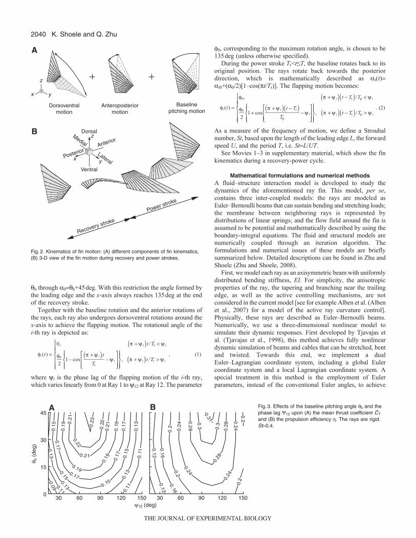
KinematicsThe flapping/rowing motions of the fin are actuated by rotations ofthe embedded rays. During the locomotion the i-th ray undergoestwo rotations simultaneously: a rotation i(t) around the x-axis (thedorsoventral motion), and a variation of the angle i(t) between thisray and the x-axis (the anteroposterior motion) (Fig.2).
Following experimental observations of labriform swimming (e.g.Drucker et al., 2006), each locomotion period T is separated intotwo sub-periods, a recovery stroke (abduction) with duration Tr anda power stroke (adduction) with duration Tp; based on observationswe choose TrTpT/2. During the recovery stroke 0≤t≤Tr, thebaseline rotates (with respect to its center) around the y axis fromits initial position to the horizontal position (i.e. baseline pitchingmotion). Meanwhile all the rays have anterior rotations sothat the angle between them and the x-axis varies asi(t)i0+(0/2)[1–cos(t/Tr)]. In our simulations we relate 0 with
Baseline
1
2
3
4
5
6
7
8
910
1211
x
z
Fig.1. Geometry and structure of a simplified pectoral fin.
THE JOURNAL OF EXPERIMENTAL BIOLOGY
2040
b through 0b+45deg. With this restriction the angle formed bythe leading edge and the x-axis always reaches 135deg at the endof the recovery stroke.
Together with the baseline rotation and the anterior rotations ofthe rays, each ray also undergoes dorsoventral rotations around thex-axis to achieve the flapping motion. The rotational angle of thei-th ray is depicted as:
where yi is the phase lag of the flapping motion of the i-th ray,which varies linearly from 0 at Ray 1 to y12 at Ray 12. The parameter
φi (t) =
0, π + ψ i( )t /Tr < ψ i
φ0
21− cos
π + ψ i( )t
Tr
− ψ i
⎡
⎣⎢⎢
⎤
⎦⎥⎥
⎧⎨⎪
⎩⎪
⎫⎬⎪
⎭⎪, π + ψ i( )t /Tr > ψ i
⎧
⎨⎪⎪
⎩⎪⎪
, (1)
K. Shoele and Q. Zhu
f0, corresponding to the maximum rotation angle, is chosen to be135deg (unless otherwise specified).
During the power stroke Tr<t≤T, the baseline rotates back to itsoriginal position. The rays rotate back towards the posteriordirection, which is mathematically described as i(t)i0+(0/2)[1–cos(t/Tr)]. The flapping motion becomes:
As a measure of the frequency of motion, we define a Strouhalnumber, St, based upon the length of the leading edge L, the forwardspeed U, and the period T, i.e. StL/UT.
See Movies 1–3 in supplementary material, which show the finkinematics during a recovery-power cycle.
Mathematical formulations and numerical methodsA fluid–structure interaction model is developed to study thedynamics of the aforementioned ray fin. This model, per se,contains three inter-coupled models: the rays are modeled asEuler–Bernoulli beams that can sustain bending and stretching loads;the membrane between neighboring rays is represented bydistributions of linear springs; and the flow field around the fin isassumed to be potential and mathematically described by using theboundary-integral equations. The fluid and structural models arenumerically coupled through an iteration algorithm. Theformulations and numerical issues of these models are brieflysummarized below. Detailed descriptions can be found in Zhu andShoele (Zhu and Shoele, 2008).
First, we model each ray as an axisymmetric beam with uniformlydistributed bending stiffness, EI. For simplicity, the anisotropicproperties of the ray, the tapering and branching near the trailingedge, as well as the active controlling mechanisms, are notconsidered in the current model [see for example Alben et al. (Albenet al., 2007) for a model of the active ray curvature control].Physically, these rays are described as Euler–Bernoulli beams.Numerically, we use a three-dimensional nonlinear model tosimulate their dynamic responses. First developed by Tjavajas etal. (Tjavajas et al., 1998), this method achieves fully nonlineardynamic simulation of beams and cables that can be stretched, bentand twisted. Towards this end, we implement a dualEuler–Lagrangian coordinate system, including a global Eulercoordinate system and a local Lagrangian coordinate system. Aspecial treatment in this method is the employment of Eulerparameters, instead of the conventional Euler angles, to achieve
φi (t) =
φ0 , π + ψ i( ) t − Tr( ) /Tp < ψ i
φ0
21+ cos
π + ψ i( ) t − Tr( )Tp
− ψ i
⎡
⎣⎢⎢
⎤
⎦⎥⎥
⎧⎨⎪
⎩⎪
⎫⎬⎪
⎭⎪, π + ψ i( ) t − Tr( ) /Tp > ψ i
⎧
⎨⎪⎪
⎩⎪⎪
. (2)Baseline
pitching motion
B
Power stroke
Recovery stroke
A
Dorsoventralmotion
Anteroposteriormotion
x y
z
Anterior
Dorsal
Ventral
Medial
LateralPosterior
x y
z
Fig.2. Kinematics of fin motion: (A) different components of fin kinematics,(B) 3-D view of the fin motion during recovery and power strokes.
0.09 0.11 0.11
0.11
0.13
0.13
0.13
0.13
0.15
0.15
0.15
0.15
0.17
0.17
0.17
0.17
0.19
0.19
0.19
0.190.
21
0.21
0.21
0.22
0.220.23
30 60 90 120 150 30 60 90 120 1500
15
30
45
ψ12 (deg)
θ b (
deg)
A
0.12
0.12
0.16
0.16
0.2
0.2
0.2
0.20.
24
0.240.
24
0.24
0.2
8
0.28
0.28
0.30
.30.31
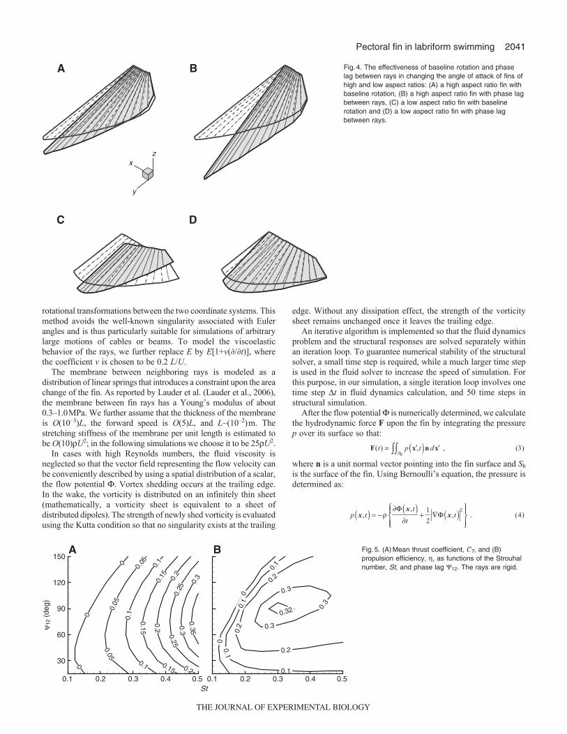
B Fig.3. Effects of the baseline pitching angle b and thephase lag 12 upon (A) the mean thrust coefficient CT
and (B) the propulsion efficiency . The rays are rigid.St0.4.
THE JOURNAL OF EXPERIMENTAL BIOLOGY
2041Pectoral fin in labriform swimming
rotational transformations between the two coordinate systems. Thismethod avoids the well-known singularity associated with Eulerangles and is thus particularly suitable for simulations of arbitrarylarge motions of cables or beams. To model the viscoelasticbehavior of the rays, we further replace E by E[1+v(�/�t)], wherethe coefficient v is chosen to be 0.2 L/U.
The membrane between neighboring rays is modeled as adistribution of linear springs that introduces a constraint upon the areachange of the fin. As reported by Lauder et al. (Lauder et al., 2006),the membrane between fin rays has a Young’s modulus of about0.3–1.0MPa. We further assume that the thickness of the membraneis O(10–3)L, the forward speed is O(5)L, and L~(10–2)m. Thestretching stiffness of the membrane per unit length is estimated tobe O(10)U2; in the following simulations we choose it to be 25U2.
In cases with high Reynolds numbers, the fluid viscosity isneglected so that the vector field representing the flow velocity canbe conveniently described by using a spatial distribution of a scalar,the flow potential . Vortex shedding occurs at the trailing edge.In the wake, the vorticity is distributed on an infinitely thin sheet(mathematically, a vorticity sheet is equivalent to a sheet ofdistributed dipoles). The strength of newly shed vorticity is evaluatedusing the Kutta condition so that no singularity exists at the trailing
edge. Without any dissipation effect, the strength of the vorticitysheet remains unchanged once it leaves the trailing edge.
An iterative algorithm is implemented so that the fluid dynamicsproblem and the structural responses are solved separately withinan iteration loop. To guarantee numerical stability of the structuralsolver, a small time step is required, while a much larger time stepis used in the fluid solver to increase the speed of simulation. Forthis purpose, in our simulation, a single iteration loop involves onetime step t in fluid dynamics calculation, and 50 time steps instructural simulation.
After the flow potential is numerically determined, we calculatethe hydrodynamic force F upon the fin by integrating the pressurep over its surface so that:
where n is a unit normal vector pointing into the fin surface and Sb
is the surface of the fin. Using Bernoulli’s equation, the pressure isdetermined as:
F(t) = p x′,t( )n d x′Sb∫∫ , (3)
p x,t( ) = −ρ∂Φ x,t( )
∂t+
1
2∇Φ x,t( ) 2⎧
⎨⎪
⎩⎪
⎫⎬⎪
⎭⎪ . (4)
x
y
z
A B
DC
Fig.4. The effectiveness of baseline rotation and phaselag between rays in changing the angle of attack of fins ofhigh and low aspect ratios: (A) a high aspect ratio fin withbaseline rotation, (B) a high aspect ratio fin with phase lagbetween rays, (C) a low aspect ratio fin with baselinerotation and (D) a low aspect ratio fin with phase lagbetween rays.
0
0
0.1
0.1
0.1
0.1
0.2
0.2
0.2
0.3
0.3
0.3
0.32
B
0
0
0
0.05
0.05
0.05
0.1
0.1
0.1
0.15
0.15
0.15
0.2
0.2
0.2
0.25
0.25
0.3
0.3
0.35
St0.1 0.2 0.3 0.4 0.5 0.1 0.2 0.3 0.4 0.5
30
60
90
120
150
ψ12
(de
g)
A Fig.5. (A)Mean thrust coefficient, CT, and (B)propulsion efficiency, , as functions of the Strouhalnumber, St, and phase lag 12. The rays are rigid.
THE JOURNAL OF EXPERIMENTAL BIOLOGY
2042
The power expenditure P is given as:
where Vb represents velocity of the body.The performance of the fin is characterized by its ability to
generate thrust force FT (the component of F in the –x direction),lift force FL (the component of F in the z direction) and lateral forceFy (the component of F in the y direction). Correspondingly, wedefine a thrust coefficient CTFT/GU2L2, a lift coefficientCLFL/GU2L2, and a lateral force coefficient CyFy/GU2L2. Anotherimportant index is the propulsion efficiency , defined as
P(t) = − p x′,t( )n ⋅Vb x′,t( )d x′Sb∫∫ , (5)
K. Shoele and Q. Zhu
FT�U/P, where FT and P represent the thrust force and powerconsumption averaged over one period T, respectively.
RESULTSEffects of kinematic parameters
Based upon experimental observations, it has been suggested thatvariations of baseline angle might be an important factordetermining the propulsive performance of pectoral fins (Lauderand Jayne, 1996; Walker and Westneat, 2002a). As mentioned byWalker (Walker, 2004), there are two mechanisms to achieve thepitching motion (i.e. the variation of the angle of attack) of the
A B
C
t /T
0 0.2 0.4 0.6 0.8 10 0.2 0.4 0.6 0.8 1
D
–0.8
–0.4
0
0.4
0.8
1.2
CL
CT
–1
0
1
2
3
–1
–0.5
0
0.5
1
P/(½
ρL2 U
2 )
–1
0
1
2
3
Cy
4
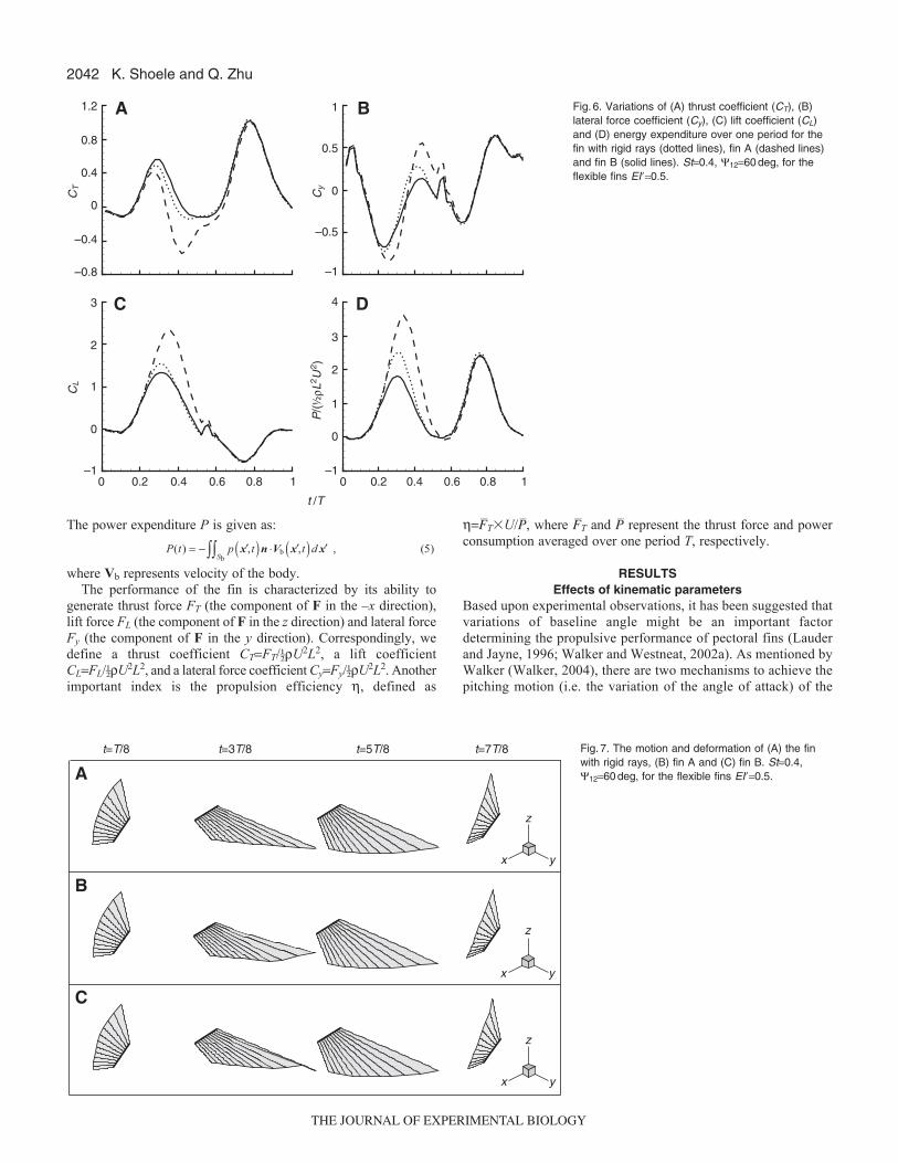
Fig.6. Variations of (A) thrust coefficient (CT), (B)lateral force coefficient (Cy), (C) lift coefficient (CL)and (D) energy expenditure over one period for thefin with rigid rays (dotted lines), fin A (dashed lines)and fin B (solid lines). St0.4, 1260deg, for theflexible fins EI�0.5.
t=7T/8t=5T/8t=3T/8t=T/8
A
C
x y
B
x y
z
z
x y
z
Fig.7. The motion and deformation of (A) the finwith rigid rays, (B) fin A and (C) fin B. St0.4,1260deg, for the flexible fins EI�0.5.
THE JOURNAL OF EXPERIMENTAL BIOLOGY
2043Pectoral fin in labriform swimming
fin. The first one is by controlling the phase differences betweenleading and trailing fin rays. This is the primary method in fisheslacking shoulder plate mobility. Through this method, a fish isable to create a large spanwise variation in the angle of attack. Bydoing this it is possible to achieve optimal pitching motion alongthe fin. The second mechanism is by reorientation of the fin root(the baseline). It is observed that in certain species, due to theexistence of joints in shoulder plates, large baseline rotations areallowed. For instance, Drucker and Lauder (Drucker and Lauder,2003) observed that trout are able to change their fin baseline angleby over 30deg. Similar behavior has been reported in boxfish(Blake, 1977). The advantage of baseline rotation is to achieve arelatively large angle between the fin and the incoming flow inthe adduction (power) phase, which in turn produces larger thrustforce. These two mechanisms of fin rotation can be combined,e.g. using phase difference between rays for drag reduction in theabduction phase to reduce power expenditure and using acombination of baseline rotation and phase lag along fin span inthe adduction phase to increase thrust force.
In order to illustrate the effects of baseline rotation and the phaselag between fin rays, we herein study the dynamic performance ofa fin with rigid rays within a range of baseline pitching angle0deg≤b≤45deg (where b0deg corresponds to the case with nobaseline rotation) and the phase lag 15deg≤12≤150deg. In Fig.3we plot the mean thrust coefficient CT, the mean lateral forcecoefficient Cy, the mean lift force coefficient CL and the propulsion
efficiency at St0.4. It is observed that the baseline rotation cansignificantly increase both CT and .
A possible factor that determines the effectiveness of phase lagbetween rays and baseline rotation is the geometry of the fin.According to Walker and Westneat (Walker and Westneat, 2002b),one of the important differences between rowing and flappingpectoral fins is their aspect ratios. This parameter also affects therelative importance of baseline rotation and phase lag in the finfeathering motion. For example, for pectoral fins with large aspectratios (slender fins), variations of the fin shape near the tip aredetermined mostly by the phase lag (Fig.4A,B). This demonstrateswhy species, such as bird wrasse (Gomphosus varius), with relativelylarge aspect ratio use mostly phase lag between rays to change theangle of attack of the fin (Walker and Westneat, 1997). For pectoralfins with lower aspect ratios, e.g. in the threespine stickleback(Gasterosteus aculeatus), the baseline rotation is more effective(Walker, 2004) (Fig.4C,D). It is worth pointing out that, besidesfin aspect ratio, there are other parameters that affect finperformance, such as fin shape, active geometry changes (Lauderand Jayne, 1996) and moments of fin area.
In the following simulations, we specify b to be 45deg.Fig.5 shows the variation of the mean thrust coefficient and the
propulsion efficiency over 0.1≤St≤0.5 and 15deg≤12≤150degfor the fin with rigid rays. In terms of the propulsion efficiency,optimal performance (around 0.32) is achieved near St~0.4 and12~90deg.
t=0 t=T/8 t=T/4 t=3T/8 t=T/2
A
C
B
x y
z
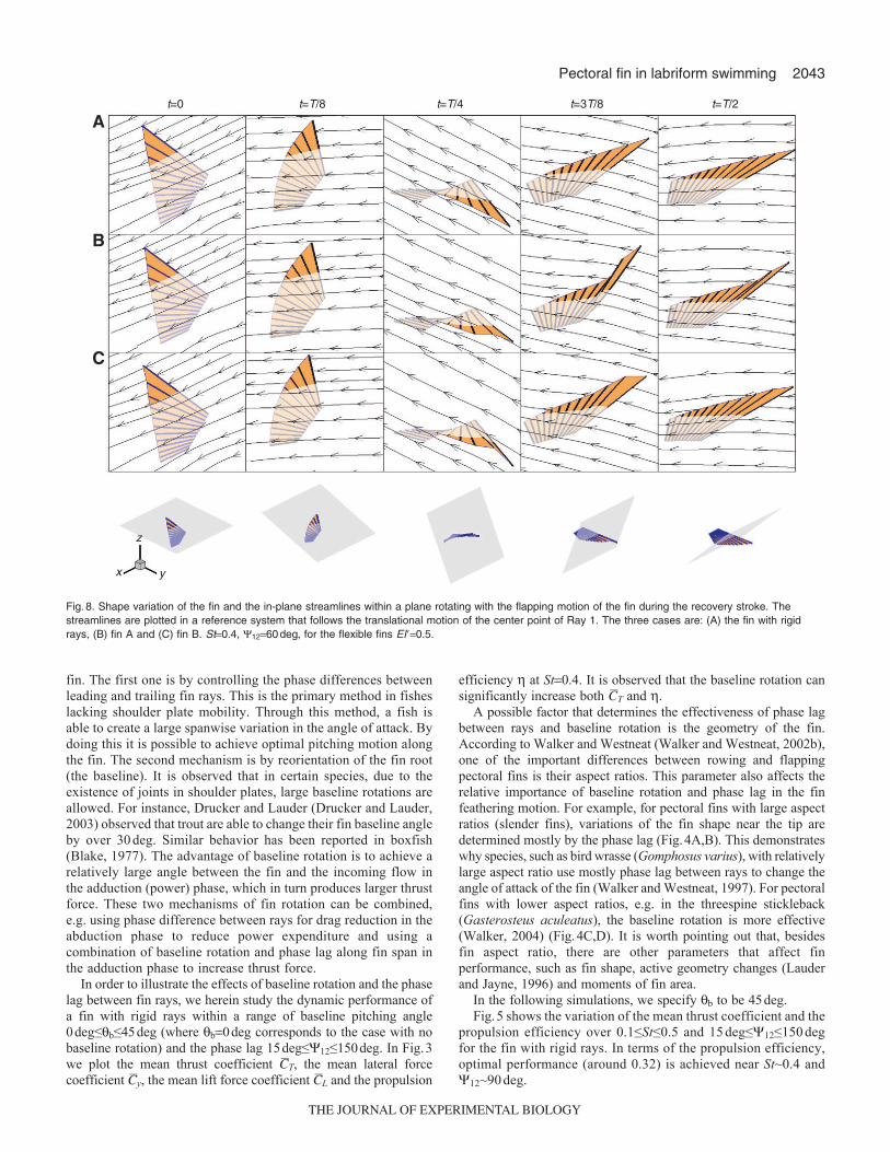
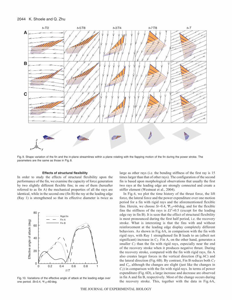
Fig.8. Shape variation of the fin and the in-plane streamlines within a plane rotating with the flapping motion of the fin during the recovery stroke. Thestreamlines are plotted in a reference system that follows the translational motion of the center point of Ray 1. The three cases are: (A) the fin with rigidrays, (B) fin A and (C) fin B. St0.4, 1260deg, for the flexible fins EI�0.5.
THE JOURNAL OF EXPERIMENTAL BIOLOGY
2044
Effects of structural flexibilityIn order to study the effects of structural flexibility upon theperformance of the fin, we examine the capacity of force generationby two slightly different flexible fins; in one of them (hereafterreferred to as fin A) the mechanical properties of all the rays areidentical, while in the second one (fin B) the ray at the leading edge(Ray 1) is strengthened so that its effective diameter is twice as
K. Shoele and Q. Zhu
large as other rays (i.e. the bending stiffness of the first ray is 15times larger than that of other rays). The configuration of the secondfin is based upon morphological observations that usually the firsttwo rays at the leading edge are strongly connected and create astiffer element (Westneat et al., 2004).
In Fig.6, we plot the time history of the thrust force, the liftforce, the lateral force and the power expenditure over one motionperiod for a fin with rigid rays and the aforementioned flexiblefins. Herein, we choose St~0.4, 1260deg, and for the flexiblefins the stiffness of the rays is EI�0.5 (except for the leadingedge ray in fin B). It is seen that the effect of structural flexibilityis most pronounced during the first half period, i.e. the recoverystroke. What is interesting is that the fins with and withoutreinforcement at the leading edge display completely differentbehaviors. As shown in Fig.6A, in comparison with the fin withrigid rays, with Ray 1 strengthened fin B leads to an (albeit notsignificant) increase in CT. Fin A, on the other hand, generates asmaller CT than the fin with rigid rays, especially near the endof the recovery stroke when it produces negative thrust. Duringthe recovery stroke, compared with the fin with rigid rays, fin Aalso creates larger forces in the vertical direction (Fig.6C) andthe lateral direction (Fig.6B). By contrast, Fin B reduces both CT
and Cy, although the changes are slight (just like the changes inCT) in comparison with the fin with rigid rays. In terms of powerexpenditure (Fig.6D), a large increase and decrease are observedin fin A and fin B, respectively. Most of the change occurs duringthe recovery stroke. This, together with the data in Fig.6A,
t=T/2 t=5T/8 t=3T/4 t=7T/8 t=T
A
C
B
x y
z
Fig.9. Shape variation of the fin and the in-plane streamlines within a plane rotating with the flapping motion of the fin during the power stroke. Theparameters are the same as those in Fig.8.
t /T
Effe
ctiv
e an
gle
of a
ttack
(de
g)
0 0.2 0.4 0.6 0.8 10
20
40
60
80Rigid fin
Fin A
Fin B
Fig.10. Variations of the effective angle of attack at the leading edge overone period. St0.4, 1260deg.
THE JOURNAL OF EXPERIMENTAL BIOLOGY
2045Pectoral fin in labriform swimming
suggests significant efficiency enhancement by fin B and decreaseby fin A. Indeed, for the particular case shown in Fig.6, thepropulsion efficiencies of the fin with rigid rays, fin A and fin Bare 0.25, 0.11 and 0.30, respectively.
We also note that in all the cases shown in Fig.6, positive thrustis generated in both the power stroke (adduction) and most of therecovery stroke (abduction) (although the thrust generated during therecovery stroke is much smaller than that during the power stroke).Besides, during the recovery stroke the fin generates a large lift force.Both of these characteristics, and even the values of CT and CL, areconsistent with measurements of species such as bird wrasse, a fishutilizing mostly flapping fin motions [see, for example, fig.3 in Walkerand Westneat (Walker and Westneat, 2002a)]. On the other hand, byapplying a smaller flapping angle f0 (e.g. f075deg), it is observedthat during the recovery stroke the fin generates mostly negative thrustforce, resembling the behavior of the threespine stickleback, a fishusing mostly rowing fin motions.
To understand the fluid–structure interaction mechanism thatcontributes to the aforementioned performance change by rayflexibility, in Fig.7 we plot snapshots of the fin deformations duringone motion period for the fin with rigid rays, fin A and fin B. Theprimary difference in the fin shape occurs near the leading edge ofthe fins as they undergo flapping/rowing motions within therecovery stroke (for example, see the snapshots at t3T/8). In finA, the leading edge bends slightly upwards against the direction ofthe downward flapping motion. This is attributed to the fact thatthe rays near the leading edge are the longest and thus least rigid.By strengthening Ray 1, it is found that the leading edge bendsdownwards towards the direction of flapping. This is expected toreduce the effective angle of attack at the leading edge. To illustratethis, in Figs8 and 9 we plot the deformation of the fin together with
the in-plane streamlines of the incoming flow measured in areference system undergoing translational motions following themotion of the center point of the leading edge. The flow velocityis projected to a plane which at t0 is parallel to the x–y plane andthen rotates following the flapping motion of the fin. The reductionof the effective angle of attack in fin B is demonstrated at botht/T/4 and t/T3/8. This effect is more clearly shown in Fig.10,where the time histories of the effective angle of attack at the centerof the leading edge are shown.
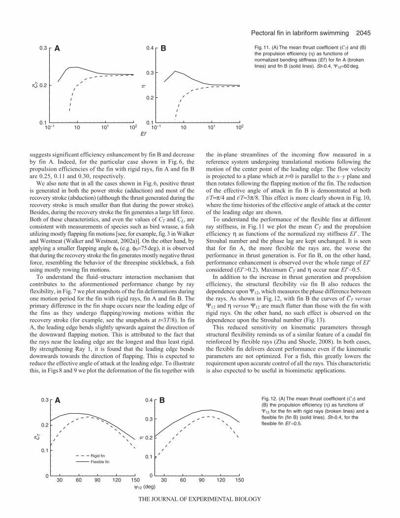
To understand the performance of the flexible fins at differentray stiffness, in Fig.11 we plot the mean CT and the propulsionefficiency as functions of the normalized ray stiffness EI�. TheStrouhal number and the phase lag are kept unchanged. It is seenthat for fin A, the more flexible the rays are, the worse theperformance in thrust generation is. For fin B, on the other hand,performance enhancement is observed over the whole range of EI�considered (EI�>0.2). Maximum CT and occur near EI�~0.5.
In addition to the increase in thrust generation and propulsionefficiency, the structural flexibility via fin B also reduces thedependence upon 12, which measures the phase difference betweenthe rays. As shown in Fig.12, with fin B the curves of CT versus12 and versus 12 are much flatter than those with the fin withrigid rays. On the other hand, no such effect is observed on thedependence upon the Strouhal number (Fig.13).
This reduced sensitivity on kinematic parameters throughstructural flexibility reminds us of a similar feature of a caudal finreinforced by flexible rays (Zhu and Shoele, 2008). In both cases,the flexible fin delivers decent performance even if the kinematicparameters are not optimized. For a fish, this greatly lowers therequirement upon accurate control of all the rays. This characteristicis also expected to be useful in biomimetic applications.
EI�10–1 10 101 102 10–1 10 101 102
0.1
0.2
0.3 A
η
0.1
0.2
0.3
0.4 B
CT–
Fig.11. (A)The mean thrust coefficient (CT) and (B)the propulsion efficiency () as functions ofnormalized bending stiffness (EI’) for fin A (brokenlines) and fin B (solid lines). St0.4, 1260deg.
Rigid fin
Flexible fin
30 60 90 120 150 30 60 90 120 150ψ12 (deg)
0.1
0
0.2
0.3 A
η
0.1
0
0.2
0.3
0.4 B
CT–
Fig.12. (A)The mean thrust coefficient (CT) and(B) the propulsion efficiency () as functions of12 for the fin with rigid rays (broken lines) and aflexible fin (fin B) (solid lines). St0.4, for theflexible fin EI�0.5.
THE JOURNAL OF EXPERIMENTAL BIOLOGY

2046
Sequence of vortex shedding and near-body flow fieldIn order to correlate the force generation with the shedding ofvortices and the induced flow in the wake, in Fig.14 we plotsnapshots of the near-body flow field at four different instants duringone period. In this particular case, the rays are rigid. No significantdifference is found between the wakes behind fins with rigid andflexible rays (fin A and fin B). Two of these snapshots are withinthe recovery stroke (tT/4 and tT/2), the other two (t3T/4 andtT) are within the power stroke. This figure displays the in-planestreamlines within the same plane that was used to depict the flownear the leading edge (ref. Figs8 and 9), although herein the flowvelocity is measured in a space-fixed reference system. This planeis defined in the following way: at the beginning of the period, thisplane intersects the leading edge at its center, and it is also parallelto the x–y plane; for the rest of the period, this plane remains parallelto the x-axis and attached to the center of the leading edge; however,
K. Shoele and Q. Zhu
it follows the flapping motion of the fin so that it rotates with respectto the x-axis.
As illustrated in Fig.14, during the recovery stroke, a pairof counter-rotating vortices (V1 and V2) is generated.Between these two vortices, a jet flow is induced. This jet formsa large angle with the x-axis, explaining the characteristic shownin Fig.6 that during the recovery stroke the fin produces largelift (Fig.6C) and lateral (Fig.6B) forces but small thrust force(Fig.6A). During the power stroke, two more vortices (V3 andV4) are created. The jet flow induced by these two, on the otherhand, is better aligned with the x-axis so that a large thrustforce and a smaller lift force are generated during the powerstroke.
ConclusionsBy using a fully coupled fluid–structure interaction model, wenumerically studied the dynamics of an idealized pectoral fin thatincludes a soft membrane reinforced by embedded beamsrepresenting fin rays. During the locomotion, a back-and-forthrowing motion and an up-and-down flapping motion are activatedthrough rotations of the rays as well as pitching of the baseline.Passive fin deformations determined by the bending of the rays areconsidered.
Through numerical simulations we have illustrated effects ofkinematic parameters and structural properties of rays upon theperformance of the fin in force generation. The key kinematic factorsare the frequency of motion (represented by the Strouhal number),the phase lag between rays, and the pitching motion of the baseline.Among these, the pitching motion of the baseline is found to increasethe thrust force and the propulsion efficiency. It is thus an importantmechanism enhancing the locomotion performance of the fish instraightline swimming.
One of the most important findings of our numerical simulationis the subtlety of the effect of structural deformability upon theperformance of the fin. Two slightly different fins, one withstrengthened leading-edge ray and the other without, displaycompletely different mechanical behaviors. In fact, withoutleading-edge ray strengthening, the propulsion performance isgreatly compromised in comparison with fins with rigid rays. Theunderlying physical mechanism involves the reduction of theeffective angle of attack at the leading edge, which diminishespower expenditure during the recovery stroke. More generally,this observation shows that the performance of the fin is affectedby spatial distribution of stiffness among the rays, as happens inreal cases where mechanical properties of rays may vary acrossthe fin.
Rigid fin
Flexible fin
A
0.1
0
0.2
0.3
0.4
0.1
0
0.2
0.3
0.4 B
ηSt
0.1 0.2 0.3 0.4 0.5 0.1 0.2 0.3 0.4 0.5
CT–
Fig.13. (A)The mean thrust coefficient (CT) and(B) the propulsion efficiency () as functions ofStrouhal number (St) for the fin with rigid rays(broken lines) and a flexible fin (fin B) (solidlines). 1260deg, for the flexible fin EI�0.5.
t=3T/4 t=T
t=T/4 t=T/2
Fig.14. Sequence of in-plane streamlines near the fin during one period ofmotion. The location of the fin is illustrated by the black circle. Thetranslational motion is from right to left. The plane is located at the centerof the leading edge and it rotates following the flapping motion of the fin.St0.4, 1260deg.
THE JOURNAL OF EXPERIMENTAL BIOLOGY
2047Pectoral fin in labriform swimming
The time history of force generation is also studied. During therecovery stroke, the fin generates a relatively small (if not negative)thrust force, the lateral force generations during the recovery andthe power strokes are comparable with each other, and the lift forcegenerated during the recovery stroke is larger than that created duringthe power stroke. This feature is correlated with the near-body flowfield. A pair of vortices is created in the recovery stroke. The inducedjet flow between them orients away from the direction of propulsion.On the other hand, the jet flow induced by another pair of vorticesshed during the power stroke is better aligned with the direction ofswimming.
LIST OF SYMBOLSCL lift coefficientCT(CT) (mean) thrust coefficientCy lateral force coefficientd thickness of the finE Young’s modulus of the raysEI� normalized bending stiffnessF hydrodynamic forceFT(FT) (mean) thrust forceL length of Ray 1 (the leading-edge ray)p hydrodynamic pressureP(P) (mean) power spentSb surface of the finSt Strouhal numbert timeT 2/ period of motionTp duration of the power strokeTr duration of the recovery strokeU forward speedVb velocity of the bodyx(x, y, z) global coordinate system0 maximum angle of rolling of each ray in one strokei angle between the i-th ray and the x-axisi0 angle between the i-th ray and the x-axis at the initial state propulsion efficiencyb pitching angle of the baselinen material damping coefficient of the rays density of fluidfi rotation of the i-th ray around the x-axis flow potentialyi phase of the i-th ray in rolling
ACKNOWLEDGEMENTSThis study was supported by the National Science Foundation under grant CBET-0844857. Computational supports from TeraGrid resources provided by the SanDiego Supercomputer Center and the National Center for SupercomputingApplications are acknowledged.
REFERENCESAlben, S., Madden, P. G. and Lauder, G. V. (2007). The mechanics of active fin-
shape control in ray-finned fishes. J. R. Soc. Interface 4, 243-256.Blake, R. W. (1977). On ostraciiform locomotion. J. Mar. Biol. Assoc. UK 57, 1047-
1055.Blake, R. W. (1979). The mechanics of labriform locomotion. I. Labriform locomotion in
the angelfish (Pterophyllum eimekei): an analysis of the power stroke. J. Exp. Biol.82, 255-271.
Blake, R. W. (1983). Fish Locomotion. Cambridge, UK: Cambridge UniversityPress.
Bozkurttas, M., Mittal, R., Dong, H., Lauder, G. V. and Madden, P. (2009). Lowdimensional models and performance scaling of a highly deformable fish pectoral fin.J. Fluid Mech. 631, 311-342.
Drucker, E. G. and Lauder, G. V. (2003). Function of pectoral fins in rainbow trout:behavioral repertoire and hydrodynamic forces, J. Exp. Biol. 206, 813-826.
Drucker, E. G., Walker, J. A. and Westneat, M. W. (2006). Mechanics of pectoral finswimming in fishes. In Fish Biomechanics, Vol. 23 (ed. R. E. Shadwick and G. V.Lauder), pp. 369-423. San Diego, CA: Elsevier Academic Press.
Gibb, A. C., Jayne, B. C. and Lauder, G. V. (1994). Kinematics of pectoral finlocomotion in the bluegill sunfish Lepomis macrochirus. J. Exp. Biol. 189, 133-161.
Harder, W. (1975). Anatomy of Fishes. Stuttgart: E. Schweizerbart’scheVerlagsbuchhandlung.
Kardong, K. V. (1998). Vertebrates: Comparative Anatomy, Function, Evolution, 2ndedn. Dubuque: W. C. Brown.
Lauder, G. V. and Jayne, B. C. (1996). Pectoral fin locomotion in fishes: testing drag-based models using three-dimensional kinematics. Am. Zool. 36, 567-581.
Lauder, G. V. and Madden, P. G. A. (2007). Fish locomotion: kinematics andhydrodynamics of flexible foil-like fins. Exp. Fluids 43, 641-653.
Lauder, G. V., Madden, P. G. A., Mittal, R., Dong, H. and Bozkurttas, M. (2006).Locomotion with flexible propulsors: I. Experimental analysis of pectoral finswimming in sunfish. Bioinspir. Biomim. 1, S25-S34.
Mittal, R., Dong, H., Bozkurttas, M., Lauder, G. V. and Madden, P. (2006).Locomotion with flexible propulsors: II. Computational modeling of pectoral finswimming in sunfish. Bioinspir. Biomim. 1, 35-41.
Shoele, K. and Zhu, Q. (2009). Fluid-structure interactions of skeleton-reinforced fins:performance analysis of a paired Fin in lift-based propulsion. J. Exp. Biol. 212, 2679-2690.
Standen, E. M. (2008). Pelvic fin locomotor function in fishes: three-dimensionalkinematics in rainbow trout (Oncorhynchus mykiss). J. Exp. Biol. 211, 2931-2942.
Tjavaras, A. A., Zhu, Q., Liu, Y., Triantafyllou, M. S. and Yue, D. K. P. (1998). Themechanics of highly-extensible cables. J. Sound Vibration 213, 709-737.
Videler, J. J. (1993). Fish Swimming. London: Chapman and Hall.Vogel, S. (1994). Life in Moving Fluids. The Physical Biology of Flow, 2nd edn.
Princeton, NJ: Princeton University Press.Walker, J. A. (2004). Dynamics of pectoral fin rowing in a fish with an extreme rowing
stroke: the threespine stickleback (Gasterosteus aculeatus). J. Exp. Biol. 207, 1925-1939.
Walker, J. A. and Westneat, M. (1997). Labriform propulsion in fishes, kinematics offlapping aquatic flight in the bird wrasse Gomphosus varius (labridae). J. Exp. Biol.200, 1549-1569.
Walker, J. A. and Westneat, M. W. (2002a). Kinematics, dynamics, and energetics ofrowing and flapping propulsion in fishes. Integr. Comp. Biol. 42, 1032-1043.
Walker, J. A. and Westneat, M. W. (2002b). Performance limits of labriformpropulsion and correlates with fin shape and motion. J. Exp. Biol. 205, 177-187.
Webb, P. W. (1973). Kinematics of pectoral fin propulsion in Cymatogaster aggregata.J. Exp. Biol. 59, 697-710.
Webb, P. W. (1994). The biology of fish swimming. In Mechanics and Physiology ofAnimal Swimming (ed. L. Maddock, Q. Bone and J. M. V. Rayner), pp. 45-62.Cambridge, UK: Cambridge University Press.
Westneat, M., Thorsen, D. H., Walker, J. A. and Hale, M. (2004). Structure, function,and neural control of pectoral fins in fishes. IEEE J. Oceanic Eng. 29, 674-683.
Zhu, Q. and Shoele, K. (2008). Propulsion performance of a skeleton-strengthenedfin. J. Exp. Biol. 211, 2087-2100.
THE JOURNAL OF EXPERIMENTAL BIOLOGY