SHAFT - tj.ba.gov.br€¦ · SHAFT SHAFT SHAFT SHAFT SHAFT N. Created Date: 9/25/2014 1:46:59 PM
Upload
abhijeet-duttaCategory
view
219download
1description
Numerical simulation based study for analyzing stability of air shaft due to depillaring around it
AbstractIn ventilating underground coal mines air shaft plays the key role. In India, bord &pillar method of mining is the prevailing method of underground coal mining. During depillaring it is highly essential to protect any damage to the air shaft. So it is recommended not to extract coal pillars in the close proximity of such ventilating structures. As any substantial instability around air shaft may adversely affect the entire mine ventilation system. So it is necessary to leave solid coal pillars around air shaft. In such case a huge quantity of good quality coal is lost in various forms of barriers. If coal extraction is done in a proper method and carrying out proper study, then such left out coal can be extracted. This is highly essential for conservation point of view. This paper aims at extracting such coal in pillars surrounding the air shaft without endangering the stability and safety of it. The paper explains the numerical simulation analysis which is conducted for the stability analysis of the air shaft and surrounding coal pillars which are left intact and a brief rock mechanics instrumentation plan. Keywords: Air shaft, Pillar design, Stowing, Angle of draw, Depillaring.IntroductionThis paper describes the methodology of extraction of coal in the pillars surrounding an air shaft in a coal mine located in southern India. The upper seam is named as No. 1 seam whereas the lower one is No. 2 seam. The 1 seam is 6.25m thick, located at depth of 44m from the surface and completely developed along the floor by Bord and Pillar method having 2.5m high galleries, with pillar size of 26m x 26m. The parting between 1 seam and 2 seam is 22m, 2 seam is having a thickness of 3.7m and completely developed by Bord and Pillar method having 3m high galleries along the floor, with pillar size of 26.8m x 26.8m. Both the seams are dipping at 1 in 9.
1Chief Scientist & Professor, CSIR-CIMFR, Dhanbad.
2Integrated MTech-PhD Student/Trainee Scientist, Academy of Scientific & Innovative Research, CSIR-CIMFR, Dhanbad.3Senior Scientist, CSIR-CIMFR, Dhanbad.
4Principal Technical Officer, CSIR-CIMFR, Dhanbad.In India as per Coal Mines Regulation, 1957 (CMR, 1957) radius of shaft pillar (R in metre) is determined by the relation,R = k1 + h1 tan 45 ̊ + h2 tanθWhere, k1 is a constant and its value taken as 50; it may be increased if other important structures like winding installations etc. are also to be protected. h1 is thickness of alluvial soil or similar loose material in m. h2 is the thickness of cover excluding the alluvial soil.θ is the angle of draw which may be taken as 25̊ for flat seams of gradient less than 15̊ .For this case the radius of shaft pillar (R) is approaching roughly 80m. So, within 80m radius usually depillaring operation is not allowed in view of safety of the air shaft. In this case study, after all the panels being depillared in both the seams, pillars lying within the radius of 80m around air shaft are thought to be left as it is. Under these conditions good quality coal will be lost forever as standing on pillars. Considering the demand of coal in India and conservation point of view, it will be very much fruitful if that coal is extracted without endangering the safety of air shaft.Numerical modeling for stability of air shaft and method of extractionIt is planned to extract the coal from the pillars by sand stowing but considering the safety of air shaft whereas one row of solid coal pillars planned to be left intact to the air shaft as shown in figure 1.
1

RibsAir Shaft
Seam 1 Working
Seam 2 Working
The phenomenon of stowing i.e. the consolidation of stowing material, multiple seam extraction and abutment stress buildup are studied using numerical modeling. For numerical modeling PLAXIS-3D which is based on finite element method is used. Due to symmetry half of the geometry is simulated. The numerical modeling is conducted in the following basic phases:Phase 1: In situ model considering the in-situ stresses.Phase 2: Development is done in both the seams.Phase 3: Depillaring i.e. splitting and slicing is conducted in seam 2 without extracting the
ribs.Phase 4: The remaining void areas including all the galleries in seam 2 working are stowed,
and the stowing is simulated by consolidation analysis.Phase 5: After extraction of seam 2, depillaring i.e. splitting and slicing is conducted in seam
1 without extracting the ribs.Phase 6: The remaining void areas including all the galleries in seam 1 working are stowed,
and the stowing is simulated.The geometry (Symmetric) of the model is shown in figure 1.
Figure 1: Numerical Simulation Model GeometryPLAXIS-3D generated mesh and Connectivity plot of the in-situ model is shown in figure 2.
2
Solid Coal Pillar

Figure 2: Generated mesh & Connectivity plotAfter splitting and slicing of coal pillar, rib pillars are left to support the overlying strata and further stowing of the remaining void areas are needed. The percentage of extraction after splitting and slicing (figure 3) is around 68.53%.
Figure 3: Pillar ExtractionIn this study vertical displacement, Stress, and factor of safety are analysed by numerical simulation. Finite element mesh has been generated by using PLAXIS-3D software, having 63891 nodes and an Average element size (Ie) of 1.748 metre. Relatively finer meshes are developed near the excavation area to get more accurate result. Figure 4 shows the vertical displacement contour shadings at the roof level of Seam 2 working. It can be observed that vertical displacement at the mine roof level is around 3.35mm after stowing.
3
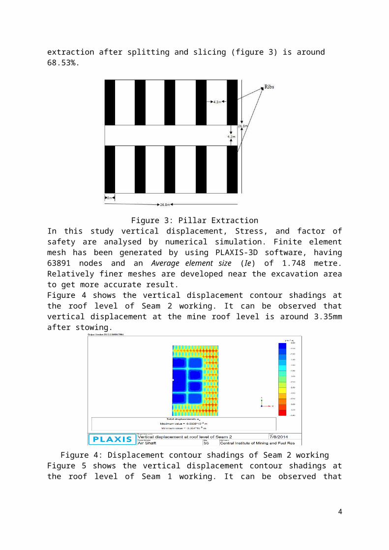
Figure 4: Displacement contour shadings of Seam 2 workingFigure 5 shows the vertical displacement contour shadings at the roof level of Seam 1 working. It can be observed that vertical displacement at the mine roof level is around 5mm after stowing.
Figure 5: Displacement contour shadings of Seam 1 workingFigure 6 shows the vertical stress (σ zz) shadings and vertical stress contour lines of the model geometry respectively. Vertical stress of maximum 5.65MPa is found.
Figure 6: vertical stress shadings & contour lines
Figure 7 shows the horizontal stress shadings and horizontal stress contour lines along x-axis (σ xx) of the model geometry respectively. Horizontal stress of maximum 2.39MPa is found.
4

Figure 7: Horizontal stress shadings & contour lines along x-axis
Figure 8 shows the horizontal stress shadings and horizontal stress contour lines along y-axis (σ yy) of the model geometry respectively. Horizontal stress of maximum 2.28MPa is found.
Figure 8: Horizontal stress shadings & contour lines along y-axis
Stress around Air Shaft boundaryFigure 9 shows vertical stress (σ zz) shadings around the air shaft boundary along the cross section A-A’. It is found to be of a maximum value around 3.37MPa.
Figure 9: Vertical stress shadings along cross section A-A’
Figure 10 shows the horizontal stress shadings along x-axis (σ xx) and horizontal stress shadings along y-axis (σ yy) of the model geometry across the cross section A-A’ respectively. Horizontal stress of maximum 1.95MPa along x-axis (σ xx) and 2.26MPa along y-axis (σ yy) is found.
5
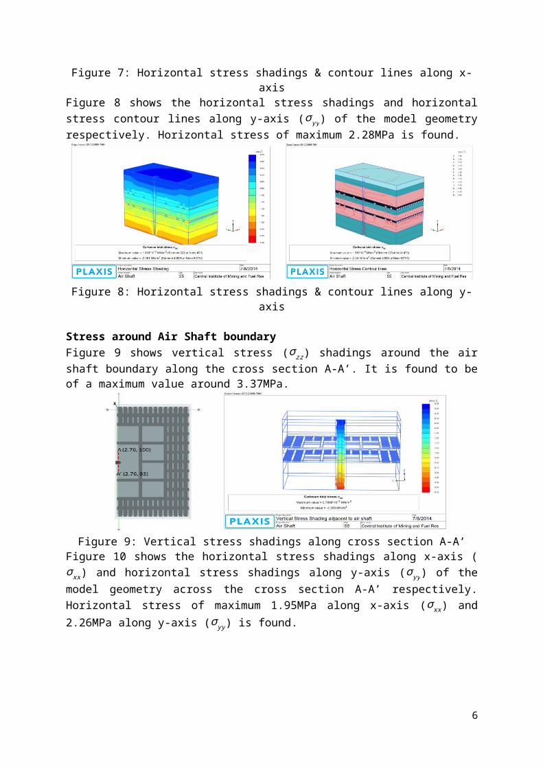
Figure 10: Horizontal stress shadings along x-axis &y-axis across the cross section A-A’
Figure 11 shows vertical stress (σ zz) shadings around the air shaft boundary along the cross section B-B’. It is found to be of a maximum value around 3.18MPa.
Figure 11: Vertical stress shadings along cross section B-B’Figure 12 shows the horizontal stress shadings along x-axis (σ xx) and horizontal stress shadings along y-axis (σ yy) of the model geometry across the cross section B-B’ respectively. Horizontal stress of maximum 1.89MPa along x-axis (σ xx) and 1.90MPa along y-axis (σ yy) is found.
Figure 12: Horizontal stress shadings along x-axis &y-axis across the cross section B-B’
Figure 13 shows vertical stress (σ zz) shadings around the air shaft boundary along the cross section C-C’. It is found to be of a maximum value around 3.14MPa.
6

Figure 13: Vertical stress shadings along cross section C-C’
Figure 14 shows the horizontal stress shadings along x-axis (σ xx) and horizontal stress shadings along y-axis (σ yy) of model geometry across the cross section C-C’ respectively. Horizontal stress of maximum 1.867MPa along x-axis (σ xx) and 1.865MPa along y-axis (σ yy) is found.
Figure 14: Horizontal stress shadings along x-axis &y-axis across the cross section C-C’For generating factor of safety curve total multiplier ΣMsf (factor of safety) is plotted against number of steps as shown in figure 15. After stowing all the remaining galleries, Factor of safety around the air shaft pillars which are left intact is found to be around 1.9 which is observed in the final step of the numerical simulation.
7

Figure 15: FOS curve Strata MonitoringFor monitoring strata behavior a detailed rock mechanics instrumentation plan is done. For monitoring stress acting on remaining pillars which are left intact around air shaft stress meters are proposed. For bed separation monitoring multipoint borehole extensometer is to be used. To measure load acting upon supports load cells are to be used. For monitoring the effect of depillaring on the air shaft at least 3 strain gauges need to be installed, one in the wall of air shaft in seam 3 working which is lying below seam 2, as the air shaft crosses one gallery in seam 3 and another strain gauge in the upper portion of air shaft nearer to surface. The third one is to be installed in the air shaft wall of seam 2 working and its connecting wire to the readout unit is to be laid through a casing. This strain gauge will be helpful for monitoring the effect during the depillaring operation.ConclusionFrom the numerical simulation study it is observed that there is no effect on the stability of air shaft by extracting the coal with sand stowing and filling all the remaining galleries around the air shaft in both the seams. For enhancing the safety of the air shaft one row of pillar around the air shaft left intact.References
1. Kaku, L. C., (2011): “The coal mine Regulation 1957”, Lovely Prakashan, p.129.2. CMRI Report (unpublished) (2014), No.-CNP/3951/2014-15.3. PLAXIS-3D (2012), Reference manual, Netherlands.
8