IEEE-810 Shaft Couplings and Shaft Runout
24
Recognized as an American National Standard (ANSI) The Institute of Electrical and Electronics Engineers, Inc. 3 Park Avenue, New York, NY 10016-5997, USA Copyright © 2001 by the Institute of Electrical and Electronics Engineers, Inc. All rights reserved. Published xx Month 2001. Printed in the United States of America. Print: ISBN 1-55937-740-2 SH11445 PDF: ISBN 0-7381-1101-5 SS11445 No part of this publication may be reproduced in any form, in an electronic retrieval system or otherwise, without the prior written permission of the publisher. IEEE Std 810-1987 (R2001) IEEE Standard for Hydraulic Turbine and Generator Integrally Forged Shaft Couplings and Shaft Runout Tolerances Sponsor Power Generation Committee of the IEEE Power Engineering Society Reaffirmed 14 May 2001 Approved 10 September 1987 IEEE-SA Standards Board Approved 2 February 1988 American National Standards Institute Abstract: Methods for blah blah blah are also included. Keywords: sizing nickel-cadmium batteries, stationary applications
description
IEEE-810 Shaft Coupling
Transcript of IEEE-810 Shaft Couplings and Shaft Runout
Recognized as anAmerican National Standard (ANSI)
The Institute of Electrical and Electronics Engineers, Inc.3 Park Avenue, New York, NY 10016-5997, USA
Copyright © 2001 by the Institute of Electrical and Electronics Engineers, Inc.All rights reserved. Published xx Month 2001. Printed in the United States of America.
Print: ISBN 1-55937-740-2 SH11445PDF: ISBN 0-7381-1101-5 SS11445
No part of this publication may be reproduced in any form, in an electronic retrieval system or otherwise, without the prior written permission of the publisher.
IEEE Std 810-1987 (R2001)
IEEE Standard for Hydraulic Turbine and Generator Integrally Forged Shaft Couplings and Shaft Runout Tolerances
SponsorPower Generation Committeeof theIEEE Power Engineering Society
Reaffirmed 14 May 2001
Approved 10 September 1987
IEEE-SA Standards Board
Approved 2 February 1988
American National Standards Institute
Abstract: Methods for blah blah blah are also included.Keywords: sizing nickel-cadmium batteries, stationary applications
IEEE Standards
documents are developed within the Technical Committees of the IEEE Societies and the StandardsCoordinating Committees of the IEEE Standards Board. Members of the committees serve voluntarily and withoutcompensation. They are not necessarily members of the Institute. The standards developed within IEEE represent aconsensus of the broad expertise on the subject within the Institute as well as those activities outside of IEEE whichhave expressed an interest in participating in the development of the standard.
Use of an IEEE Standard is wholly voluntary. The existence of an IEEE Standard does not imply that there are no otherways to produce, test, measure, purchase, market, or provide other goods and services related to the scope of the IEEEStandard. Furthermore, the viewpoint expressed at the time a standard is approved and issued is subject to changebrought about through developments in the state of the art and comments received from users of the standard. EveryIEEE Standard is subjected to review at least once every Þve years for revision or reafÞrmation. When a document ismore than Þve years old, and has not been reafÞrmed, it is reasonable to conclude that its contents, although still ofsome value, do not wholly reßect the present state of the art. Users are cautioned to check to determine that they havethe latest edition of any IEEE Standard.
Comments for revision of IEEE Standards are welcome from any interested party, regardless of membership afÞliationwith IEEE. Suggestions for changes in documents should be in the form of a proposed change of text, together withappropriate supporting comments.
Interpretations: Occasionally questions may arise regarding the meaning of portions of standards as they relate tospeciÞc applications. When the need for interpretations is brought to the attention of IEEE, the Institute will initiateaction to prepare appropriate responses. Since IEEE Standards represent a consensus of all concerned interests, it isimportant to ensure that any interpretation has also received the concurrence of a balance of interests. For this reasonIEEE and the members of its technical committees are not able to provide an instant response to interpretation requestsexcept in those cases where the matter has previously received formal consideration.
Comments on standards and requests for interpretations should be addressed to:
Secretary, IEEE Standards Board345 East 47th StreetNew York, NY 10017USA
IEEE Standards documents are adopted by the Institute of Electrical and Electronics Engineers without regard towhether their adoption may involve patents on articles, materials, or processes. Such adoption does not assumeany liability to any patent owner, nor does it assume any obligation whatever to parties adopting the standardsdocuments.
iii
Foreword
(This Foreword is not a part of ANSI/IEEE Std 810-1987, IEEE Standard for Hydraulic Turbine and Generator Integrally ForgedShaft Couplings and Shaft Runout Tolerances.)
This standard details dimensions of integrally ßanged shafts and couplings, such as are used for the connectionbetween the generator and turbine in hydroelectric installations. It was originally developed by the American Societyof Mechanical Engineers (ASME) in 1928 and approved for publication by the American Standards Association(ASA) in 1932. A revised version, sponsored by ASME, was approved by ASA in 1947 and identiÞed asStandard B49.1.
Starting in 1953 the National Electrical Manufacturers Association (NEMA) undertook the sponsorship of thestandard and a revised issue was approved in 1967 by the United States of America Standards Institute (USA StandardsInstitute superseded the ASA in 1966).
NEMA elected to withdraw their sponsorship of Standard B49.1 in 1985, and in 1985 the Institute of Electrical andElectronics Engineers (IEEE) agreed to sponsor it. The Hydroelectric Power Sub-committee of the IEEE PowerGeneration Committee undertook the task of reviewing, revising, and reissuing the standard.
NEMA also sponsored Standards MG 5.1, Large Hydraulic-Turbine-Driven Synchronous Generators and ReversibleSynchronous Generator/Motor Units for Pumped Storage Installations and MG 5.2, Installation of Vertical Hydraulic-Turbine-Driven Generators and Reversible Generator/Motors for Pumped Storage Installations. Both of thesestandards contained tables concerning the ÒAllowable Runout Tolerance.Ó Since MG 5.1 (rescinded in 1982) and MG5.2 (rescinded in 1983) have been withdrawn by NEMA, these tolerance data have been included in this standard.
The working group wishes to acknowledge the contributions made to the standard by R. D. Handel and D. H.Hohnstein.
At the time this standard was approved, the members of the Working Group were as follows:
D. J. Parker
, Chair
F. L. BrennanD. L. Evans
P. S. Johrde J. M. QuigleyD. H. Thomas
iv
The following persons were on the balloting committee that approved this document for submission to the IEEEStandards Board:
W. W. AvrilM. S. BaldwinJ. H. BellackI. B. BerezowskiG. G. BoyleF. L. BrennanJ. B. CannonR. W. CantrellR. L. CastleberryE. F. ChelottiR. E. CottaM. L. CrenshawD. J. DamskerP. M. DavidsonD. Diamant
G. R. EngmannW. M. FennerA. H. FerberN. R. FriedmanD. I. GordenR. K. GuptaM. E. JackowskiW. D. JacksonJ. H. JonesC. E. KneeburgP. R. LandrieuJ. E. LeclairP. A. LewisG. L. LuriJ. T. MadillO. S. Mazzoni
D. R. McCabeG. R. MeloyM. W. MigliaroJ. T. NikolasR. E. PennC. R. PopeR. RamakumarR. J. ReimanD. E. RobertsE. P. RothongA. J. SpurginG. I. StillmanJ. E. Stoner, JrJ. B. SullivanR. Zweigler
v
When the IEEE Standards Board approved this standard on September 10, 1987, it had the following membership:
Donald C. Fleckenstein
, Chair
Marco W. Migliaro
, Vice Chair
Andrew G. Salem
, Secretary
James H. BeallDennis BodsonMarshall L. CainJames M. DalyStephen R. DillonEugene P. FogartyJay ForsterKenneth D. HendrixIrvin N. Howell
Leslie R. KerrJack KinnIrving KolodnyJoseph L. Koepfinger*Edward LohseJohn MayLawrence V. McCallL. Bruce McClungDonald T. Michael*
L. John RankineJohn P. RiganatiGary S. RobinsonFrank L. RoseRobert E. RountreeSava I. Sherr*William R. TackaberryWilliam B. WilkensHelen M. Wood
* Member emeritus
vi
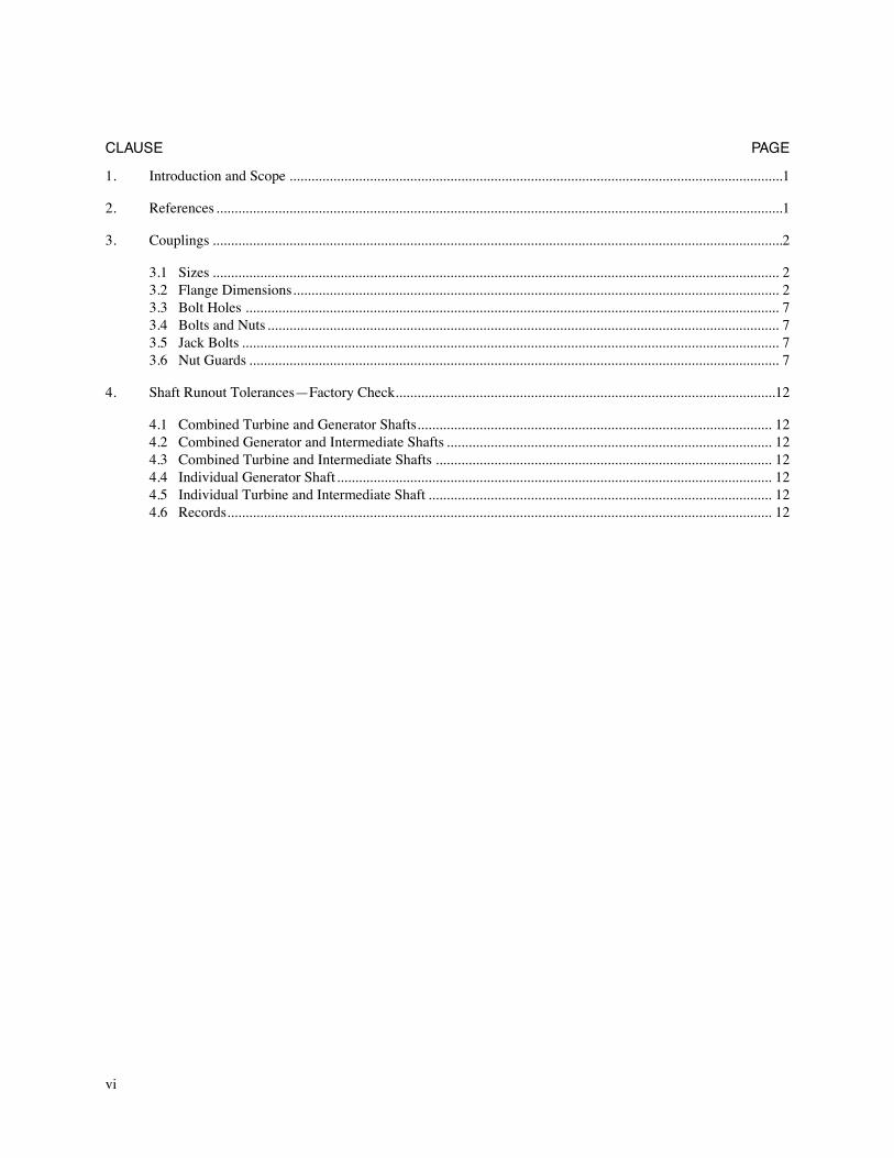
CLAUSE PAGE
1. Introduction and Scope .......................................................................................................................................1
2. References ...........................................................................................................................................................1
3. Couplings ............................................................................................................................................................2
3.1 Sizes ........................................................................................................................................................... 23.2 Flange Dimensions..................................................................................................................................... 23.3 Bolt Holes .................................................................................................................................................. 73.4 Bolts and Nuts ............................................................................................................................................ 73.5 Jack Bolts ................................................................................................................................................... 73.6 Nut Guards ................................................................................................................................................. 7
4. Shaft Runout TolerancesÑFactory Check........................................................................................................12
4.1 Combined Turbine and Generator Shafts................................................................................................. 124.2 Combined Generator and Intermediate Shafts ......................................................................................... 124.3 Combined Turbine and Intermediate Shafts ............................................................................................ 124.4 Individual Generator Shaft....................................................................................................................... 124.5 Individual Turbine and Intermediate Shaft .............................................................................................. 124.6 Records..................................................................................................................................................... 12
Copyright © 1988 IEEE All Rights Reserved
1
An American National Standard
IEEE Standard for Hydraulic Turbine and Generator Integrally Forged Shaft Couplings and Shaft Runout Tolerances
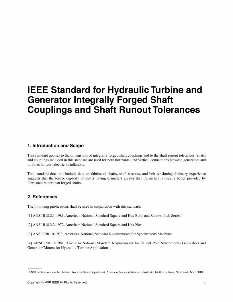
1. Introduction and Scope
This standard applies to the dimensions of integrally forged shaft couplings and to the shaft runout tolerances. Shaftsand couplings included in this standard are used for both horizontal and vertical connections between generators andturbines in hydroelectric installations.
This standard does not include data on fabricated shafts, shaft stresses, and bolt tensioning. Industry experiencesuggests that the torque capacity of shafts having diameters greater than 72 inches is usually better provided byfabricated rather than forged shafts.
2. References
The following publications shall be used in conjunction with this standard:
[1] ANSI B18.2.1-1981, American National Standard Square and Hex Bolts and Screws, Inch Series.
1
[2] ANSI B18.2.2-1972, American National Standard Square and Hex Nuts.
[3] ANSI C50.10-1977, American National Standard Requirements for Synchronous Machines.
[4] ANSI C50.12-1981, American National Standard Requirements for Salient Pole Synchronous Generators andGenerator/Motors for Hydraulic Turbine Applications.
1
ANSI publications can be obtained from the Sales Department. American National Standards Institute, 1430 Broadway, New York, NY 10018.
2
Copyright © 1988 IEEE All Rights Reserved
IEEE Std 810-1987 IEEE STANDARD FOR HYDRAULIC TURBINE AND INTEGRALLY
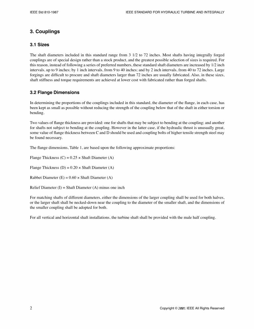
3. Couplings
3.1 Sizes
The shaft diameters included in this standard range from 3 1/2 to 72 inches. Most shafts having integrally forgedcouplings are of special design rather than a stock product, and the greatest possible selection of sizes is required. Forthis reason, instead of following a series of preferred numbers, these standard shaft diameters are increased by 1/2 inchintervals, up to 9 inches; by 1 inch intervals, from 9 to 40 inches; and by 2 inch intervals, from 40 to 72 inches. Largeforgings are difÞcult to procure and shaft diameters larger than 72 inches are usually fabricated. Also, in these sizes,shaft stiffness and torque requirements are achieved at lower cost with fabricated rather than forged shafts.
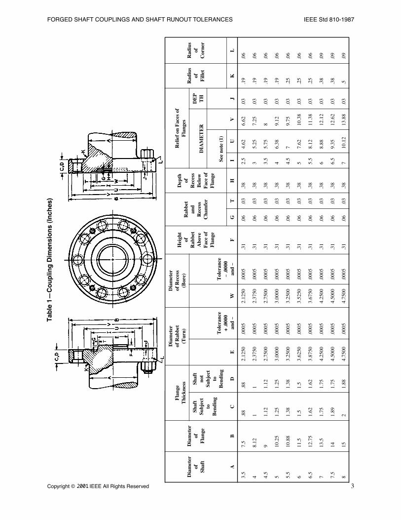
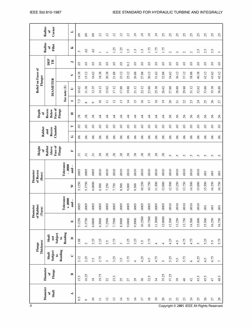
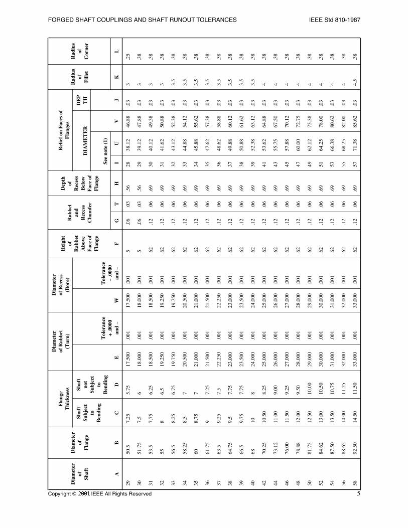
3.2 Flange Dimensions
In determining the proportions of the couplings included in this standard, the diameter of the ßange, in each case, hasbeen kept as small as possible without reducing the strength of the coupling below that of the shaft in either torsion orbending.
Two values of ßange thickness are provided: one for shafts that may be subject to bending at the coupling; and anotherfor shafts not subject to bending at the coupling. However in the latter case, if the hydraulic thrust is unusually great,some value of ßange thickness between C and D should be used and coupling bolts of higher tensile strength steel maybe found necessary.
The ßange dimensions, Table 1, are based upon the following approximate proportions:
Flange Thickness (C) = 0.25
´
Shaft Diameter (A)
Flange Thickness (D) = 0.20
´
Shaft Diameter (A)
Rabbet Diameter (E) = 0.60
´
Shaft Diameter (A)
Relief Diameter (I) = Shaft Diameter (A) minus one inch
For matching shafts of different diameters, either the dimensions of the larger coupling shall be used for both halves,or the larger shaft shall be necked-down near the coupling to the diameter of the smaller shaft, and the dimensions ofthe smaller coupling shall be adopted for both.
For all vertical and horizontal shaft installations, the turbine shaft shall be provided with the male half coupling.
Copyright © 1988 IEEE All Rights Reserved
3
FORGED SHAFT COUPLINGS AND SHAFT RUNOUT TOLERANCES IEEE Std 810-1987
Tab
le 1
ÑC
ou
plin
g D
imen
sio
ns
(In
ches
)
Dia
met
erof
Shaf
t
Dia
met
erof
Fla
nge
Fla
nge
Thi
ckne
ss
Dia
met
erof
Rab
bet
(Tur
n)
Dia
met
erof
Rec
ess
(Bor
e)H
eigh
tof
Rab
bet
Abo
veF
ace
ofF
lang
e
Rab
bet
and
Rec
ess
Cha
mfe
r
Dep
thof
Rec
ess
Bel
owF
ace
ofF
lang
e
Rel
ief
on F
aces
of
Fla
nges
Rad
ius
ofF
illet
Rad
ius
ofC
orne
rSh
aft
Subj
ect
toB
endi
ng
Shaf
tno
tSu
bjec
tto
Ben
ding
E
Tol
eran
ce+
.000
0an
d
-
W
Tol
eran
ce
-
.000
0an
d
-
DIA
ME
TE
RD
EP
TH
See
note
(1)
VJ
AB
CD
FG
TH
IU
KL
3.5
7.5
.88
.88
2.12
50.0
005
2.12
50.0
005
.31
.06
.03
.38
2.5
4.62
6.62
.03
.19
.06
48.
121
12.
3750
.000
52.
3750
.000
5.3
1.0
6.0
3.3
83
5.25
7.25
.03
.19
.06
4.5
91.
121.
122.
7500
.000
52.
7500
.000
5.3
1.0
6.0
3.3
83.
55.
758
.03
.19
.06
510
.25
1.25
1.25
3.00
00.0
005
3.00
00.0
005
.31
.06
.03
.38
46.
389.
12.0
3.1
9.0
6
5.5
10.8
81.
381.
383.
2500
.000
53.
2500
.000
5.3
1.0
6.0
3.3
84.
57
9.75
.03
.25
.06
611
.51.
51.
53.
6250
.000
53.
5250
.000
5.3
1.0
6.0
3.3
85
7.62
10.3
8.0
3.2
5.0
6
6.5
12.7
51.
621.
623.
8750
.000
53.
6750
.000
5.3
1.0
6.0
3.3
85.
58.
1211
.38
.03
.25
.06
713
.51.
751.
754.
2500
.000
54.
2500
.000
5.3
1.0
6.0
3.3
86
8.88
12.1
2.0
3.3
8.0
9
7.5
141.
891.
754.
5000
.000
54.
5000
.000
5.3
1.0
6.0
3.3
86.
59.
3512
.62
.03
.38
.09
815
21.
884.
7500
.000
54.
7500
.000
5.3
1.0
6.0
3.3
87
10.1
213
.88
.03
.5.0
9
4
Copyright © 1988 IEEE All Rights Reserved
IEEE Std 810-1987 IEEE STANDARD FOR HYDRAULIC TURBINE AND INTEGRALLY
8.5
15.5
2.12
1.88
5.12
50.0
005
5.12
50.0
005
.31
.06
.03
.38
7.5
10.6
214
.38
.03
.5.0
9
916
.25
2.25
25.
3750
.000
55.
3750
.000
5.3
1.0
6.0
3.3
88
11.3
815
.12
.03
.62
.09
1018
2.5
2.25
6.00
00.0
005
6.00
00.0
005
.31
.06
.03
.38
912
.35
16.6
2.0
3.6
2.0
9
1119
.75
2.75
2.25
6.50
00.0
005
6.50
0.0
010
.38
.06
.03
.44
1014
.12
18.3
8.0
31
.12
1222
32.
57.
2500
.000
57.
250
.001
0.3
8.0
6.0
3.4
411
15.6
220
.38
.03
1.1
2
1323
.53.
252.
757.
7500
.000
57.
750
.001
0.3
8.0
6.0
3.4
412
17.1
221
.88
.03
1.25
.12
1425
3.5
38.
5000
.000
58.
500
.001
0.3
8.0
6.0
3.4
413
17.8
823
.12
.03
1.25
.12
1527
3.75
3.25
9.00
00.0
005
9.00
0.0
010
.38
.06
.03
.44
1419
.88
25.1
20.
31.
5.1
2
1629
43.
259.
5000
.000
59.
500
.001
0.3
8.0
6.0
3.4
415
21.1
226
.88
.03
1.5
.19
1730
4.25
3.5
10.2
500
.000
510
.250
.001
0.3
8.0
6.0
3.4
416
22.1
227
.88
.03
1.5
.19
1832
.54.
53.
7510
.750
0.0
005
10.7
50.0
010
.38
.06
.03
.44
1723
.88
30.1
2.0
31.
75.1
9
1934
4.75
411
.500
0.0
005
11.5
00.0
010
.38
.06
.03
.44
1825
.38
31.6
2.0
31.
75.1
9
2035
.25
54
12.0
000
.000
512
.000
.001
0.3
8.0
6.0
3.4
419
26.6
232
.88
.03
1.75
.25
2137
.25
5.25
4.25
12.5
00.0
010
12.5
00.0
010
.5.0
6.0
3.5
620
27.8
834
.62
.03
2.2
5
2239
5.5
4.5
13.2
50.0
010
13.2
50.0
010
.5.0
6.0
3.5
621
28.8
836
.12
.03
2.2
5
2340
5.75
4.75
13.7
50.0
010
13.7
50.0
010
.5.0
6.0
3.5
622
29.8
837
.12
.03
2.2
5
2442
64.
7514
.500
.001
014
.500
.001
0.5
.06
.03
.56
2331
.12
38.8
8.0
32
.25
2543
.56.
255
15.0
00.0
010
15.0
00.0
010
.5.0
6.0
3.5
624
32.6
240
.38
.03
2.5
.25
2645
.56.
55.
2515
.500
.001
15.5
00.0
01.5
.06
.03
.56
2533
.88
42.1
2.0
32.
5.2
5
2747
6.75
5.5
16.2
50.0
0116
.250
.001
.5.0
6.0
3.5
626
35.3
843
.62
.03
2.5
.25
2848
.57
5.75
16.7
50.0
0116
.750
.001
.5.0
6.0
3.5
627
36.8
845
.12
.03
3.2
5
Dia
met
erof
Shaf
t
Dia
met
erof
Fla
nge
Fla
nge
Thi
ckne
ss
Dia
met
erof
Rab
bet
(Tur
n)
Dia
met
erof
Rec
ess
(Bor
e)H
eigh
tof
Rab
bet
Abo
veF
ace
ofF
lang
e
Rab
bet
and
Rec
ess
Cha
mfe
r
Dep
thof
Rec
ess
Bel
owF
ace
ofF
lang
e
Rel
ief
on F
aces
of
Fla
nges
Rad
ius
ofF
illet
Rad
ius
ofC
orne
rSh
aft
Subj
ect
toB
endi
ng
Shaf
tno
tSu
bjec
tto
Ben
ding
E
Tol
eran
ce+
.000
0an
d
-
W
Tol
eran
ce
-
.000
0an
d
-
DIA
ME
TE
RD
EP
TH
See
note
(1)
VJ
AB
CD
FG
TH
IU
KL
Copyright © 1988 IEEE All Rights Reserved
5
FORGED SHAFT COUPLINGS AND SHAFT RUNOUT TOLERANCES IEEE Std 810-1987
2950
.57.
255.
7517
.500
.001
17.5
00.0
01.5
.06
.03
.56
2838
.12
46.8
8.0
33
.25
3051
.75
7.5
618
.000
.001
18.0
00.0
01.5
.06
.03
.56
2939
.12
47.8
8.0
33
.38
3153
.57.
756.
2518
.500
.001
18.5
00.0
01.6
2.1
2.0
6.6
930
40.1
249
.38
.03
3.3
8
3255
86.
519
.250
.001
19.2
50.0
01.6
2.1
2.0
6.6
931
41.6
250
.88
.03
3.3
8
3356
.58.
256.
7519
.750
.001
19.7
50.0
01.6
2.1
2.0
6.6
932
43.1
252
.38
.03
3.5
.38
3458
.25
8.5
720
.500
.001
20.5
00.0
01.6
2.1
2.0
6.6
933
44.8
854
.12
.03
3.5
.38
3560
8.75
721
.000
.001
21.0
00.0
01.6
2.1
2.0
6.6
934
45.8
855
.62
.03
3.5
.38
3661
.75
97.
2521
.500
.001
21.5
00.0
01.6
2.1
2.0
6.6
935
47.6
257
.38
.03
3.5
.38
3763
.59.
257.
522
.250
.001
22.2
50.0
01.6
2.1
2.0
6.6
936
48.6
258
.88
.03
3.5
.38
3864
.75
9.5
7.75
23.0
00.0
0123
.000
.001
.62
.12
.06
.69
3749
.88
60.1
2.0
33.
5.3
8
3966
.59.
757.
7523
.500
.001
23.5
00.0
01.6
2.1
2.0
6.6
938
50.8
861
.62
.03
3.5
.38
4068
108
24.0
00.0
0124
.000
.001
.62
.12
.06
.69
3952
.38
63.1
2.0
33.
5.3
8
4270
.25
10.5
08.
2525
.000
.001
25.0
00.0
01.6
2.1
2.0
6.6
941
53.6
264
.88
.03
4.3
8
4473
.12
11.0
09.
0026
.000
.001
26.0
00.0
01.6
2.1
2.0
6.6
943
55.7
567
.50
.03
4.3
8
4676
.00
11.5
09.
2527
.000
.001
27.0
00.0
01.6
2.1
2.0
6.6
945
57.8
870
.12
.03
4.3
8
4878
.88
12.0
09.
5028
.000
.001
28.0
00.0
01.6
2.1
2.0
6.6
947
60.0
072
.75
.03
4.3
8
5081
.75
12.5
010
.00
29.0
00.0
0129
.000
.001
.62
.12
.06
.69
4962
.12
75.3
8.0
34
.38
5284
.62
13.0
010
.50
30.0
00.0
0130
.000
.001
.62
.12
.06
.69
5164
.25
78.0
0.0
34
.38
5487
.50
13.5
010
.75
31.0
00.0
0131
.000
.001
.62
.12
.06
.69
5366
.38
80.6
2.0
34
.38
5688
.62
14.0
011
.25
32.0
00.0
0132
.000
.001
.62
.12
.06
.69
5568
.25
82.0
0.0
34
.38
5892
.50
14.5
011
.50
33.0
00.0
0133
.000
.001
.62
.12
.06
.69
5771
.38
85.6
2.0
34.
5.3
8
Dia
met
erof
Shaf
t
Dia
met
erof
Fla
nge
Fla
nge
Thi
ckne
ss
Dia
met
erof
Rab
bet
(Tur
n)
Dia
met
erof
Rec
ess
(Bor
e)H
eigh
tof
Rab
bet
Abo
veF
ace
ofF
lang
e
Rab
bet
and
Rec
ess
Cha
mfe
r
Dep
thof
Rec
ess
Bel
owF
ace
ofF
lang
e
Rel
ief
on F
aces
of
Fla
nges
Rad
ius
ofF
illet
Rad
ius
ofC
orne
rSh
aft
Subj
ect
toB
endi
ng
Shaf
tno
tSu
bjec
tto
Ben
ding
E
Tol
eran
ce+
.000
0an
d
-
W
Tol
eran
ce
-
.000
0an
d
-
DIA
ME
TE
RD
EP
TH
See
note
(1)
VJ
AB
CD
FG
TH
IU
KL
6
Copyright © 1988 IEEE All Rights Reserved
IEEE Std 810-1987 IEEE STANDARD FOR HYDRAULIC TURBINE AND INTEGRALLY
NO
TE
S:
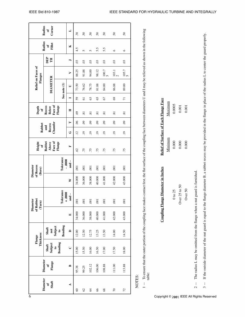
1 Ñ
To
ensu
re th
at th
e ou
ter p
ortio
n of
the
coup
ling
face
mak
es c
onta
ct Þ
rst,
the
ßat s
urfa
ce o
f the
cou
plin
g fa
ce b
etw
een
diam
eter
s U
and
I m
ay b
e re
lieve
d as
sho
wn
in th
e fo
llow
ing
tabl
e:
2 Ñ
The
rad
ius
L m
ay b
e om
itted
fro
m th
e ßa
nge
whe
n a
nut g
uard
is f
urni
shed
.
3 Ñ
If
the
outs
ide
diam
eter
of
the
nut g
uard
is e
qual
to th
e ßa
nge
diam
eter
B, a
rab
bet r
eces
s m
ay b
e pr
ovid
ed in
the
ßang
e in
pla
ce o
f th
e ra
dius
L to
cen
ter
the
guar
d pr
oper
ly.
6095
.38
15.0
012
.00
34.0
00.0
0134
.000
.001
.62
.12
.06
.69
5973
.50
88.2
5.0
34.
5.3
8
6299
.25
15.5
012
.50
36.0
00.0
0136
.000
.001
.75
.19
.09
.81
6176
.62
91.8
8.0
35
.50
6410
2.12
16.0
012
.75
38.0
00.0
0138
.000
.001
.75
.19
.09
.81
6378
.75
94.0
0.0
35
.50
6610
6.00
16.5
013
.25
40.0
00.0
0140
.000
.001
.75
.19
.09
.81
6581
.88
98.1
2.0
35.
5.5
0
6810
8.88
17.0
013
.50
41.0
00.0
0141
.000
.001
.75
.19
.09
.81
6784
.00
100.
75
.03
5.5
.50
7011
1.00
17.5
014
.00
42.0
00.0
0142
.000
.001
.75
.19
.09
.81
6986
.88
103.
12
.03
6.5
0
7211
3.88
18.0
014
.50
43.0
00.0
0143
.000
.001
.75
.19
.09
.81
7189
.00
105.
75
.03
6.5
0
Cou
plin
g F
lang
e D
iam
eter
in I
nche
sR
elie
f of
Sur
face
of
Eac
h F
lang
e F
ace
Min
imum
Max
imum
0 to
25
0.00
00.
0005
Ove
r 25
to 5
00.
000
0.00
1
Ove
r 50
0.00
00.
001
Dia
met
erof
Shaf
t
Dia
met
erof
Fla
nge
Fla
nge
Thi
ckne
ss
Dia
met
erof
Rab
bet
(Tur
n)
Dia
met
erof
Rec
ess
(Bor
e)H
eigh
tof
Rab
bet
Abo
veF
ace
ofF
lang
e
Rab
bet
and
Rec
ess
Cha
mfe
r
Dep
thof
Rec
ess
Bel
owF
ace
ofF
lang
e
Rel
ief
on F
aces
of
Fla
nges
Rad
ius
ofF
illet
Rad
ius
ofC
orne
rSh
aft
Subj
ect
toB
endi
ng
Shaf
tno
tSu
bjec
tto
Ben
ding
E
Tol
eran
ce+
.000
0an
d
-
W
Tol
eran
ce
-
.000
0an
d
-
DIA
ME
TE
RD
EP
TH
See
note
(1)
VJ
AB
CD
FG
TH
IU
KL
Copyright © 1988 IEEE All Rights Reserved
7
FORGED SHAFT COUPLINGS AND SHAFT RUNOUT TOLERANCES IEEE Std 810-1987
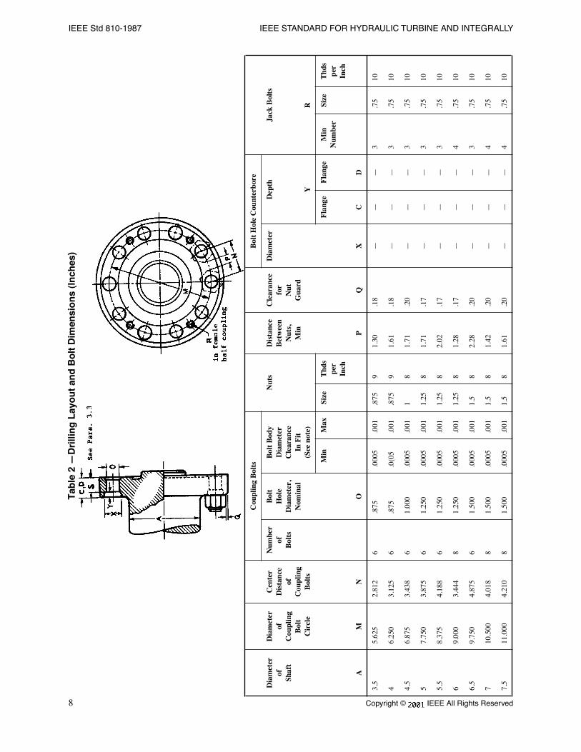
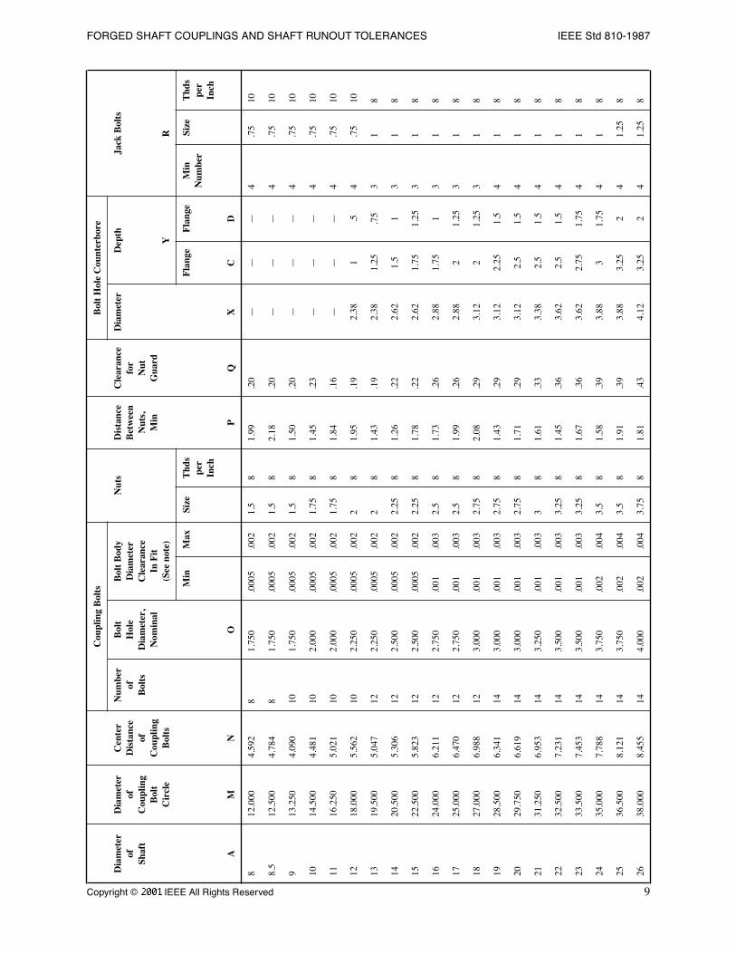
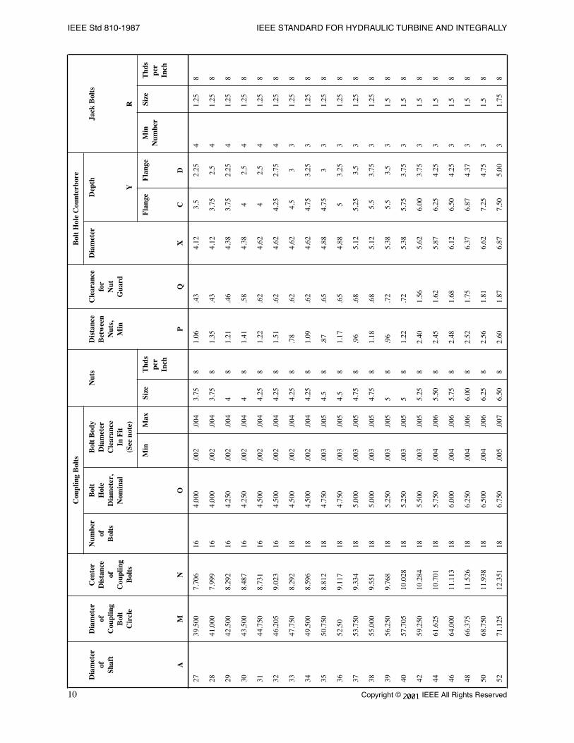
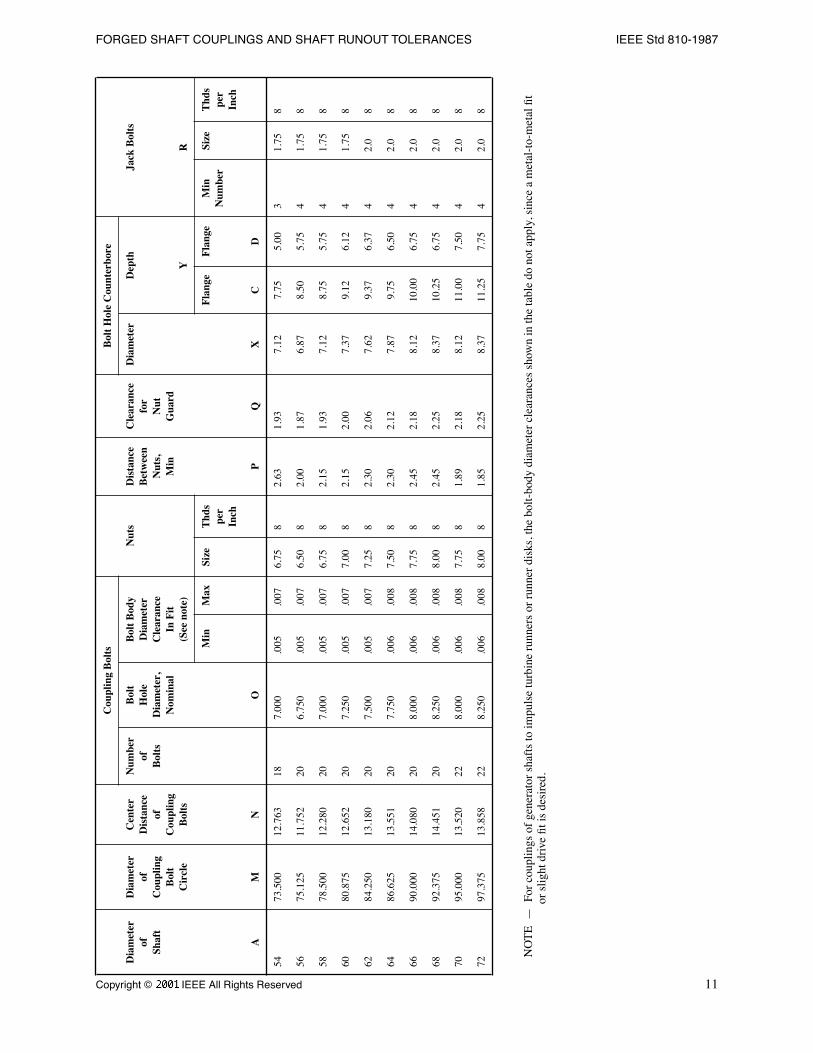
3.3 Bolt Holes
Shafts 12 inches and larger in diameter shall have the bolt holes counterbored from the back of the ßange to facilitatebolt placement. The depth of this counterbore shall be such that the length (in each ßange) of the reamed portion S,Table 2, of the bolt hole is at least 0.8 times the nominal body diameter of the bolt.
3.4 Bolts and Nuts
The number and diameter of the bolts are based upon the assumption that the torque is transmitted only by shear in thebolts and that the combined stress in the bolts may safely be as much as 30% greater than the combined stress in theshaft. The diameter of the bolt body shall be determined from information given in Table 2.
NOTE Ñ Hexagon head, round head, or stud bolts with nuts at both ends, may be used for all bolt diameters up to and including5.25 inches at the discretion of the manufacturer. For bolts above 5.25 inches in diameter, the use of stud bolts with roundnuts is recommended. The dimensions. listed in Tables 1 and 2 of this standard for shaft diameters of 42 inches and largerwere based on this recommendation. For shaft diameters up to and including 9 inches, hexagon nuts were used todetermine ßange diameter. Heavy hexagon nuts were used for all other shaft sizes up to and including 40 inches.
The hexagon bolt heads (if used) shall correspond to the dimensions given in ANSI B18.2.1-1981 [1]
2
. Bolt heads shallbe of the same size as the nuts, or of the size corresponding to the body diameter of the bolts. In the latter case, one ßatshall be placed parallel to the periphery of the ßange to provide clearance for the nut guard.
The nuts shall correspond to the dimensions given in ANSI B18-2.2-1972 [2], and shall be of the sizes shown in Table2 of this standard.
Bolt heads and nuts beyond the sizes listed in ANSI B18.2.1-1981[1] and ANSI B18.2.2-1972 [2] shall bedimensioned in accordance with the formulas given in Appendix II of each of those standards. When used, round nutsor bolt heads shall have a diameter equal to or greater than the across ßat dimensions given in those standards.
The bolts shall be straight (not tapered) and shall be Þtted individually within the clearances speciÞed in Table 2. Thebolts and bolt holes shall be identiÞed with corresponding numbers to facilitate assembly.
The length of the bolts shall be such that they will project slightly beyond the nuts. The diameter of this projectingportion, which is provided for driving when the bolts are being assembled or removed, shall be smaller than the rootdiameter of the thread. The number of threads per inch shall be as given in Table 2.
3.5 Jack Bolts
The jack bolts shall be furnished with the female half coupling for both vertical and horizontal shafts.
The diameter and number of threads per inch shall be as indicated in Table 2. The length shall suit the thickness of thecoupling.
3.6 Nut Guards
In order to permit the installation of nut guards of the same outside diameter as the ßange (Table 1, Dimension B), aclearance Q has been provided between the edge of the ßange and the nuts.
NOTE Ñ The nut guard may also be allowed to overlap the ßange.
2
The numbers in brackets correspond to those of the references listed in Section 2.
8
Copyright © 1988 IEEE All Rights Reserved
IEEE Std 810-1987 IEEE STANDARD FOR HYDRAULIC TURBINE AND INTEGRALLY
Tab
le 2
ÑD
rilli
ng
Lay
ou
t an
d B
olt
Dim
ensi
on
s (I
nch
es)
Cou
plin
g B
olts
Bol
t H
ole
Cou
nter
bore
Dia
met
erof
Shaf
t
Dia
met
erof
Cou
plin
gB
olt
Cir
cle
Cen
ter
Dis
tanc
eof
Cou
plin
gB
olts
Num
ber
ofB
olts
Bol
tH
ole
Dia
met
er,
Nom
inal
Bol
t B
ody
Dia
met
erC
lear
ance
In F
it(S
ee n
ote)
Nut
sD
ista
nce
Bet
wee
nN
uts,
Min
Cle
aran
cefo
rN
utG
uard
Dia
met
erD
epth
Jack
Bol
ts
YR
Min
Max
Size
Thd
spe
rIn
ch
Fla
nge
Fla
nge
Min
Num
ber
Size
Thd
spe
rIn
ch
AM
NO
PQ
XC
D
3.5
5.62
52.
812
6.8
75.0
005
.001
.875
91.
30.1
8Ñ
ÑÑ
3.7
510
46.
250
3.12
56
.875
.0(0
5.0
01.8
759
1.61
.18
ÑÑ
Ñ3
.75
10
4.5
6.87
53.
438
61.
000
.000
5.0
011
81.
71.2
0Ñ
ÑÑ
3.7
510
57.
750
3.87
56
1.25
0.0
005
.001
1.25
81.
71.1
7Ñ
ÑÑ
3.7
510
5.5
8.37
54.
188
61.
250
.000
5.0
011.
258
2.02
.17
ÑÑ
Ñ3
.75
10
69.
000
3.44
48
1.25
0.0
005
.001
1.25
81.
28.1
7Ñ
ÑÑ
4.7
510
6.5
9.75
04.
875
61.
500
.000
5.0
011.
58
2.28
.20
ÑÑ
Ñ3
.75
10
710
.500
4.01
88
1.50
0.0
005
.001
1.5
81.
42.2
0Ñ
ÑÑ
4.7
510
7.5
11.0
004.
210
81.
500
.000
5.0
011.
58
1.61
.20
ÑÑ
Ñ4
.75
10
Copyright © 1988 IEEE All Rights Reserved
9
FORGED SHAFT COUPLINGS AND SHAFT RUNOUT TOLERANCES IEEE Std 810-1987
812
.000
4.59
28
1.75
0.0
005
.002
1.5
81.
99.2
0Ñ
ÑÑ
4.7
510
8.5
12.5
004.
784
81.
750
.000
5.0
021.
58
2.18
.20
ÑÑ
Ñ4
.75
10
913
.250
4.09
010
1.75
0.0
005
.002
1.5
81.
50.2
0Ñ
ÑÑ
4.7
510
1014
.500
4.48
110
2.00
0.0
005
.002
1.75
81.
45.2
3Ñ
ÑÑ
4.7
510
1116
.250
5.02
110
2.00
0.0
005
.002
1.75
81.
84.1
6Ñ
ÑÑ
4.7
510
1218
.000
5.56
210
2.25
0.0
005
.002
28
1.95
.19
2.38
1.5
4.7
510
1319
.500
5.04
712
2.25
0.0
005
.002
28
1.43
.19
2.38
1.25
.75
31
8
1420
.500
5.30
612
2.50
0.0
005
.002
2.25
81.
26.2
22.
621.
51
31
8
1522
.500
5.82
312
2.50
0.0
005
.002
2.25
81.
78.2
22.
621.
751.
253
18
1624
.000
6.21
112
2.75
0.0
01.0
032.
58
1.73
.26
2.88
1.75
13
18
1725
.000
6.47
012
2.75
0.0
01.0
032.
58
1.99
.26
2.88
21.
253
18
1827
.000
6.98
812
3.00
0.0
01.0
032.
758
2.08
.29
3.12
21.
253
18
1928
.500
6.34
114
3.00
0.0
01.0
032.
758
1.43
.29
3.12
2.25
1.5
41
8
2029
.750
6.61
914
3.00
0.0
01.0
032.
758
1.71
.29
3.12
2.5
1.5
41
8
2131
.250
6.95
314
3.25
0.0
01.0
033
81.
61.3
33.
382.
51.
54
18
2232
.500
7.23
114
3.50
0.0
01.0
033.
258
1.45
.36
3.62
2.5
1.5
41
8
2333
.500
7.45
314
3.50
0.0
01.0
033.
258
1.67
.36
3.62
2.75
1.75
41
8
2435
.000
7.78
814
3.75
0.0
02.0
043.
58
1.58
.39
3.88
31.
754
18
2536
.500
8.12
114
3.75
0.0
02.0
043.
58
1.91
.39
3.88
3.25
24
1.25
8
2638
.000
8.45
514
4.00
0.0
02.0
043.
758
1.81
.43
4.12
3.25
24
1.25
8
Cou
plin
g B
olts
Bol
t H
ole
Cou
nter
bore
Dia
met
erof
Shaf
t
Dia
met
erof
Cou
plin
gB
olt
Cir
cle
Cen
ter
Dis
tanc
eof
Cou
plin
gB
olts
Num
ber
ofB
olts
Bol
tH
ole
Dia
met
er,
Nom
inal
Bol
t B
ody
Dia
met
erC
lear
ance
In F
it(S
ee n
ote)
Nut
sD
ista
nce
Bet
wee
nN
uts,
Min
Cle
aran
cefo
rN
utG
uard
Dia
met
erD
epth
Jack
Bol
ts
YR
Min
Max
Size
Thd
spe
rIn
ch
Fla
nge
Fla
nge
Min
Num
ber
Size
Thd
spe
rIn
ch
AM
NO
PQ
XC
D
10
Copyright © 1988 IEEE All Rights Reserved
IEEE Std 810-1987 IEEE STANDARD FOR HYDRAULIC TURBINE AND INTEGRALLY
2739
.500
7.70
616
4.00
0.0
02.0
043.
758
1.06
.43
4.12
3.5
2.25
41.
258
2841
.000
7.99
916
4.00
0.0
02.0
043.
758
1.35
.43
4.12
3.75
2.5
41.
258
2942
.500
8.29
216
4.25
0.0
02.0
044
81.
21.4
64.
383.
752.
254
1.25
8
3043
.500
8.48
716
4.25
0.0
02.0
044
81.
41.5
84.
384
2.5
41.
258
3144
.750
8.73
116
4.50
0.0
02.0
044.
258
1.22
.62
4.62
42.
54
1.25
8
3246
.205
9.02
316
4.50
0.0
02.0
044.
258
1.51
.62
4.62
4.25
2.75
41.
258
3347
.750
8.29
218
4.50
0.0
02.0
044.
258
.78
.62
4.62
4.5
33
1.25
8
3449
.500
8.59
618
4.50
0.0
02.0
044.
258
1.09
.62
4.62
4.75
3.25
31.
258
3550
.750
8.81
218
4.75
0.0
03.0
054.
58
.87
.65
4.88
4.75
33
1.25
8
3652
.50
9.11
718
4.75
0.0
03.0
054.
58
1.17
.65
4.88
53.
253
1.25
8
3753
.750
9.33
418
5.00
0.0
03.0
054.
758
.96
.68
5.12
5.25
3.5
31.
258
3855
.000
9.55
118
5.00
0.0
03.0
054.
758
1.18
.68
5.12
5.5
3.75
31.
258
3956
.250
9.76
818
5.25
0.0
03.0
055
8.9
6.7
25.
385.
53.
53
1.5
8
4057
.705
10.0
2818
5.25
0.0
03.0
055
81.
22.7
25.
385.
753.
753
1.5
8
4259
.250
10.2
8418
5.50
0.0
03.0
055.
258
2.40
1.56
5.62
6.00
3.75
31.
58
4461
.625
10.7
0118
5.75
0.0
04.0
065.
508
2.45
1.62
5.87
6.25
4.25
31.
58
4664
.000
11.1
1318
6.00
0.0
04.0
065.
758
2.48
1.68
6.12
6.50
4.25
31.
58
4866
.375
11.5
2618
6.25
0.0
04.0
066.
008
2.52
1.75
6.37
6.87
4.37
31.
58
5068
.750
11.9
3818
6.50
0.0
04.0
066.
258
2.56
1.81
6.62
7.25
4.75
31.
58
5271
.125
12.3
5118
6.75
0.0
05.0
076.
508
2.60
1.87
6.87
7.50
5.00
31.
758
Cou
plin
g B
olts
Bol
t H
ole
Cou
nter
bore
Dia
met
erof
Shaf
t
Dia
met
erof
Cou
plin
gB
olt
Cir
cle
Cen
ter
Dis
tanc
eof
Cou
plin
gB
olts
Num
ber
ofB
olts
Bol
tH
ole
Dia
met
er,
Nom
inal
Bol
t B
ody
Dia
met
erC
lear
ance
In F
it(S
ee n
ote)
Nut
sD
ista
nce
Bet
wee
nN
uts,
Min
Cle
aran
cefo
rN
utG
uard
Dia
met
erD
epth
Jack
Bol
ts
YR
Min
Max
Size
Thd
spe
rIn
ch
Fla
nge
Fla
nge
Min
Num
ber
Size
Thd
spe
rIn
ch
AM
NO
PQ
XC
D
Copyright © 1988 IEEE All Rights Reserved
11
FORGED SHAFT COUPLINGS AND SHAFT RUNOUT TOLERANCES IEEE Std 810-1987
NO
TE
Ñ F
or c
oupl
ings
of
gene
rato
r sh
afts
to im
puls
e tu
rbin
e ru
nner
s or
run
ner
disk
s, th
e bo
lt-bo
dy d
iam
eter
cle
aran
ces
show
n in
the
tabl
e do
not
app
ly, s
ince
a m
etal
-to-
met
al Þ
tor
slig
ht d
rive
Þt i
s de
sire
d.
5473
.500
12.7
6318
7.00
0.0
05.0
076.
758
2.63
1.93
7.12
7.75
5.00
31.
758
5675
.125
11.7
5220
6.75
0.0
05.0
076.
508
2.00
1.87
6.87
8.50
5.75
41.
758
5878
.500
12.2
8020
7.00
0.0
05.0
076.
758
2.15
1.93
7.12
8.75
5.75
41.
758
6080
.875
12.6
5220
7.25
0.0
05.0
077.
008
2.15
2.00
7.37
9.12
6.12
41.
758
6284
.250
13.1
8020
7.50
0.0
05.0
077.
258
2.30
2.06
7.62
9.37
6.37
42.
08
6486
.625
13.5
5120
7.75
0.0
06.0
087.
508
2.30
2.12
7.87
9.75
6.50
42.
08
6690
.000
14.0
8020
8.00
0.0
06.0
087.
758
2.45
2.18
8.12
10.0
06.
754
2.0
8
6892
.375
14.4
5120
8.25
0.0
06.0
088.
008
2.45
2.25
8.37
10.2
56.
754
2.0
8
7095
.000
13.5
2022
8.00
0.0
06.0
087.
758
1.89
2.18
8.12
11.0
07.
504
2.0
8
7297
.375
13.8
5822
8.25
0.0
06.0
088.
008
1.85
2.25
8.37
11.2
57.
754
2.0
8
Cou
plin
g B
olts
Bol
t H
ole
Cou
nter
bore
Dia
met
erof
Shaf
t
Dia
met
erof
Cou
plin
gB
olt
Cir
cle
Cen
ter
Dis
tanc
eof
Cou
plin
gB
olts
Num
ber
ofB
olts
Bol
tH
ole
Dia
met
er,
Nom
inal
Bol
t B
ody
Dia
met
erC
lear
ance
In F
it(S
ee n
ote)
Nut
sD
ista
nce
Bet
wee
nN
uts,
Min
Cle
aran
cefo
rN
utG
uard
Dia
met
erD
epth
Jack
Bol
ts
YR
Min
Max
Size
Thd
spe
rIn
ch
Fla
nge
Fla
nge
Min
Num
ber
Size
Thd
spe
rIn
ch
AM
NO
PQ
XC
D
12
Copyright © 1988 IEEE All Rights Reserved
IEEE Std 810-1987 IEEE STANDARD FOR HYDRAULIC TURBINE AND INTEGRALLY
4. Shaft Runout TolerancesÑFactory Check
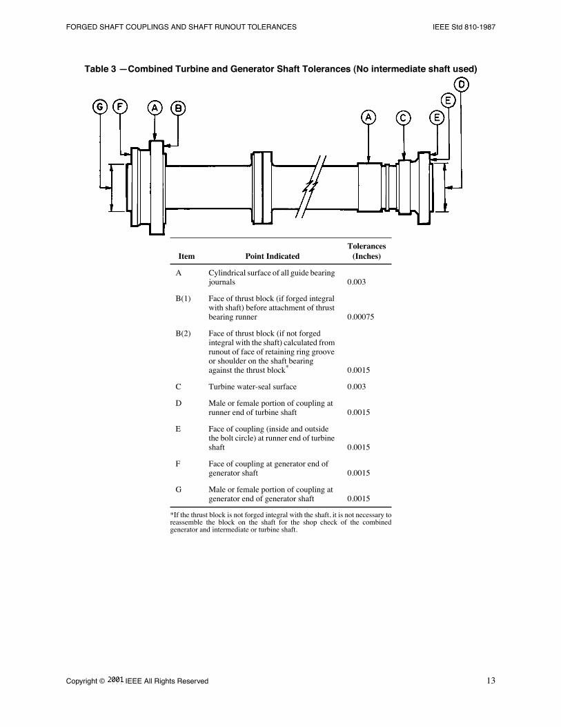
4.1 Combined Turbine and Generator Shafts
When the alignment of the combined turbine and generator shafts is checked at the factory, it shall be done by rotatingthe shafts in a lathe or on a vertical alignment table. The couplings should be match marked before disassembly. Theamount of runout, determined by the reading of an indicator held stationary with respect to the lathe or table, shall notexceed the tolerances of Table 3.
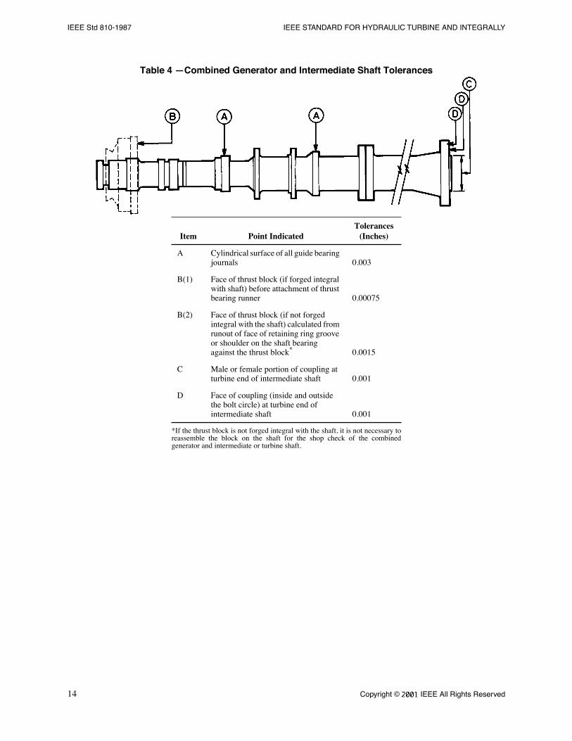
4.2 Combined Generator and Intermediate Shafts
The tolerances on the runout when checked in the same manner as described in 4.1 shall not exceed those of Table 4.
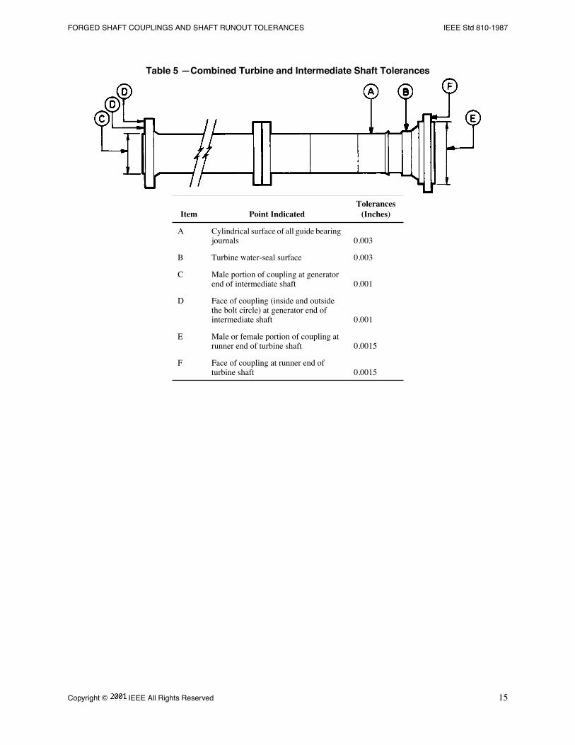
4.3 Combined Turbine and Intermediate Shafts
The tolerance on the runout when checked in the same manner described in 4.1 shall not exceed those of Table 5.
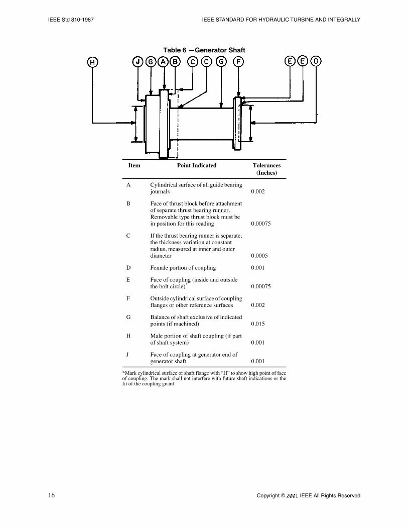
4.4 Individual Generator Shaft
When the shafts are to be aligned at a location other than the generatorÕs manufacturerÕs factory, the tolerances on therunout of the individual generator shaft when checked in the same manner as that described in 4.1 shall not exceedthose of Table 6.
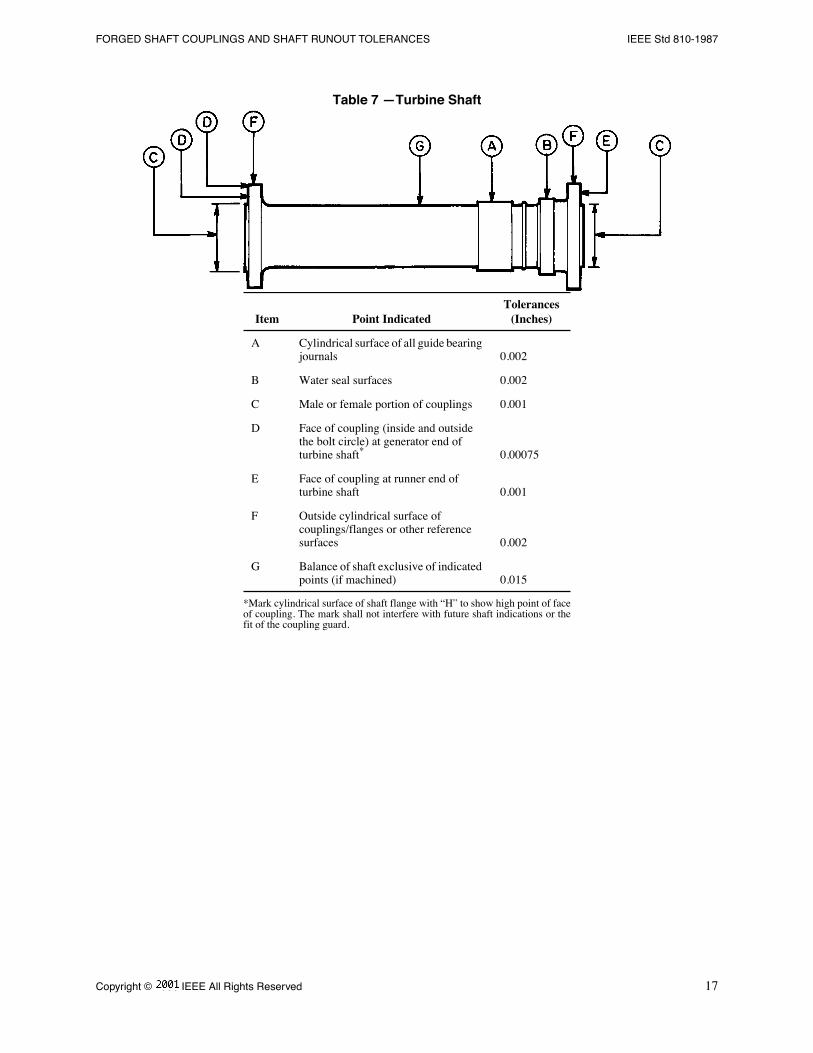
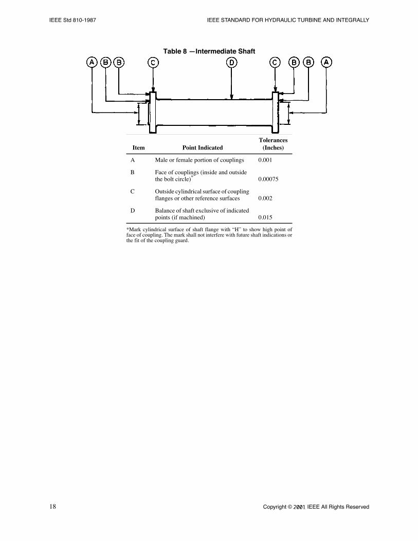
4.5 Individual Turbine and Intermediate Shaft
Experience indicates that the prescribed tolerances on the combined shafts will usually be met if the runout, when theshafts are checked individually in the same manner as that described in 4.1, does not exceed the tolerances of Table 7for turbine shafts and Table 8 for intermediate shafts.
4.6 Records
A shaft alignment drawing shall be prepared showing the location of shaft check points and measurement values forthe information of the Þeld erector.
Copyright © 1988 IEEE All Rights Reserved
13
FORGED SHAFT COUPLINGS AND SHAFT RUNOUT TOLERANCES IEEE Std 810-1987
Table 3 ÑCombined Turbine and Generator Shaft Tolerances (No intermediate shaft used)
Item Point IndicatedTolerances
(Inches)
A Cylindrical surface of all guide bearing journals 0.003
B(1) Face of thrust block (if forged integral with shaft) before attachment of thrust bearing runner 0.00075
B(2) Face of thrust block (if not forged integral with the shaft) calculated from runout of face of retaining ring groove or shoulder on the shaft bearing against the thrust block
*
*If the thrust block is not forged integral with the shaft, it is not necessary toreassemble the block on the shaft for the shop check of the combinedgenerator and intermediate or turbine shaft.
0.0015
C Turbine water-seal surface 0.003
D Male or female portion of coupling at runner end of turbine shaft 0.0015
E Face of coupling (inside and outside the bolt circle) at runner end of turbine shaft 0.0015
F Face of coupling at generator end of generator shaft 0.0015
G Male or female portion of coupling at generator end of generator shaft 0.0015
14
Copyright © 1988 IEEE All Rights Reserved
IEEE Std 810-1987 IEEE STANDARD FOR HYDRAULIC TURBINE AND INTEGRALLY
Table 4 ÑCombined Generator and Intermediate Shaft Tolerances
Item Point IndicatedTolerances
(Inches)
A Cylindrical surface of all guide bearing journals 0.003
B(1) Face of thrust block (if forged integral with shaft) before attachment of thrust bearing runner 0.00075
B(2) Face of thrust block (if not forged integral with the shaft) calculated from runout of face of retaining ring groove or shoulder on the shaft bearing against the thrust block
*
*If the thrust block is not forged integral with the shaft, it is not necessary toreassemble the block on the shaft for the shop check of the combinedgenerator and intermediate or turbine shaft.
0.0015
C Male or female portion of coupling at turbine end of intermediate shaft 0.001
D Face of coupling (inside and outside the bolt circle) at turbine end of intermediate shaft 0.001
Copyright © 1988 IEEE All Rights Reserved
15
FORGED SHAFT COUPLINGS AND SHAFT RUNOUT TOLERANCES IEEE Std 810-1987
Table 5 ÑCombined Turbine and Intermediate Shaft Tolerances
Item Point IndicatedTolerances
(Inches)
A Cylindrical surface of all guide bearing journals 0.003
B Turbine water-seal surface 0.003
C Male portion of coupling at generator end of intermediate shaft 0.001
D Face of coupling (inside and outside the bolt circle) at generator end of intermediate shaft 0.001
E Male or female portion of coupling at runner end of turbine shaft 0.0015
F Face of coupling at runner end of turbine shaft 0.0015
16
Copyright © 1988 IEEE All Rights Reserved
IEEE Std 810-1987 IEEE STANDARD FOR HYDRAULIC TURBINE AND INTEGRALLY
Table 6 ÑGenerator Shaft
Item Point Indicated Tolerances(Inches)
A Cylindrical surface of all guide bearing journals 0.002
B Face of thrust block before attachment of separate thrust bearing runner. Removable type thrust block must be in position for this reading 0.00075
C If the thrust bearing runner is separate, the thickness variation at constant radius, measured at inner and outer diameter 0.0005
D Female portion of coupling 0.001
E Face of coupling (inside and outside the bolt circle)
*
*Mark cylindrical surface of shaft flange with ÒHÓ to show high point of faceof coupling. The mark shall not interfere with future shaft indications or thefit of the coupling guard.
0.00075
F Outside cylindrical surface of coupling flanges or other reference surfaces 0.002
G Balance of shaft exclusive of indicated points (if machined) 0.015
H Male portion of shaft coupling (if part of shaft system) 0.001
J Face of coupling at generator end of generator shaft 0.001
Copyright © 1988 IEEE All Rights Reserved
17
FORGED SHAFT COUPLINGS AND SHAFT RUNOUT TOLERANCES IEEE Std 810-1987
Table 7 ÑTurbine Shaft
Item Point IndicatedTolerances
(Inches)
A Cylindrical surface of all guide bearing journals 0.002
B Water seal surfaces 0.002
C Male or female portion of couplings 0.001
D Face of coupling (inside and outside the bolt circle) at generator end of turbine shaft
*
*Mark cylindrical surface of shaft flange with ÒHÓ to show high point of faceof coupling. The mark shall not interfere with future shaft indications or thefit of the coupling guard.
0.00075
E Face of coupling at runner end of turbine shaft 0.001
F Outside cylindrical surface of couplings/flanges or other reference surfaces 0.002
G Balance of shaft exclusive of indicated points (if machined) 0.015
18
Copyright © 1988 IEEE All Rights Reserved
IEEE Std 810-1987 IEEE STANDARD FOR HYDRAULIC TURBINE AND INTEGRALLY
Table 8 ÑIntermediate Shaft
Item Point IndicatedTolerances
(Inches)
A Male or female portion of couplings 0.001
B Face of couplings (inside and outside the bolt circle)
*
*Mark cylindrical surface of shaft flange with ÒHÓ to show high point offace of coupling. The mark shall not interfere with future shaft indications orthe fit of the coupling guard.
0.00075
C Outside cylindrical surface of coupling flanges or other reference surfaces 0.002
D Balance of shaft exclusive of indicated points (if machined) 0.015