Numerical Modelling of Large Deflection Behaviour of...
25
Numerical Modelling of Large Deflection Behaviour of Restrained Reinforced Concrete Beams in Fire Sherwan Albrifkani Supervisors: Professor Yong Wang Dr Zhenjun Yang [email protected] The Steel in Fire Forum (StiFF) London, April 2015
Transcript of Numerical Modelling of Large Deflection Behaviour of...

Numerical Modelling of Large Deflection Behaviour of Restrained Reinforced Concrete Beams in Fire
Sherwan Albrifkani
Supervisors:
Professor Yong Wang
Dr Zhenjun Yang
The Steel in Fire Forum (StiFF) London, April 2015

Introduction
Methodology of ABAQUS modelling
Large deflection behaviour of restrained RC beams in fire
Summary
Questions
Outline

Introduction

Approaches of evaluating fire resistance of structural elements
Prescriptive-Based Approach
Standard fire resistance tests.
The provisions based on standard tests do not address the:
Effects of realistic fire conditions.
Interaction among structural members within a frame.
Global response of frames in fire.
Restraint conditions.
Performance-based approach
Fire severity.
Material properties at elevated temperatures.
Member interactions.
Load level.
Restraint conditions.
This approach considers the:
Introduction

Cardington full-scale fire tests on framed structures
Towards Performance-based approach
The Cardington full-scale fire tests demonstrated that the real behaviour of structural members within a frame can be very different from that indicated by standard fire tests.
Alternative load paths are likely to be available at lager deflections, such as membrane action in floor slabs and catenary action in beams that are not possible at small deflections.
Introduction

- The experiences from Cardington tests have pushed researchers to fill the knowledge gaps in understanding the fire performance of structures subject to lager deformations.
- Considerable survival of beams in fire may be ensured from catenary action.
w
w
Under flexural action
Under catenary action Fire tests on steel beam-column sub-assemblages
Recent studies on large deflection behaviour of restrained beams in fire
Introduction

Introduction
Fire safety research of restrained RC beams have been limited to the beam performance at small deflections.
Knowledge gap
- The current research work intents to address the knowledge gap in catenary action contribution to the fire safety improvement of RC beams.
Def
lect
ion
(m
m)
Fire exposure time
Axi
al f
orc
e
Fire exposure time
Compression
Tension
Under flexural action Under flexural action
Under catenary
action
Under
catenary
action

Methodology of ABAQUS modelling
Finite element modelling of RC structures using ABAQUS
BM
Failed column
P N
N
(b) catenary action for top bars in beam
BM
Failed column
P
N N BE BE
BM
(c) catenary action for top and bottom bars in beam
BE
Failed column
P
N N
(d) catenary action for bottom bars in beam
(a) compressive arch action
BE
BM
BE
BM
Failed column
N N
P
w
A typical beam under catenary action
Challenges of simulating large deflection behaviour of RC beams in fire subject to: - Extreme deformations. - Material and geometry non-linearity. - Material damage. - Temporary instability.
Finite element modelling of RC structures using ABAQUS
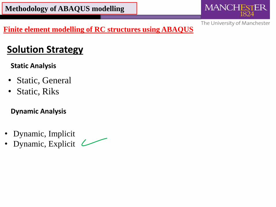
Solution Strategy
• Static, General
• Static, Riks
Static Analysis
Dynamic Analysis
• Dynamic, Implicit
• Dynamic, Explicit
Methodology of ABAQUS modelling
Producing a quasi-static response using Explicit dynamic analysis
Speeding up the simulation by artificially: - scaling the real time to a very small time period. - Increasing the material density (Mass scaling).
Introducing damping to the numerical model
Methodology of ABAQUS modelling

An example illustrating the selection of appropriate loading speed and
damping ratio
RC beam-column sub-ssemblage by Yu and Tan (2011)
Methodology of ABAQUS modelling

Displacement-controlled procedure Reduce the time period
Effect of rate of loading on the numerical behaviour of the sub-assemblage
Stable
Catenary action
capacity Flexural capacity
Load
Displacement
Applied
displacement
-300
-250
-200
-150
-100
-50
0
50
100
150
200
250
0 100 200 300 400 500 600 700
Ho
rizo
nta
l rea
ctio
n (
kN)
Middle joint displacement (mm)
(a) Load-middle joint displacement
(b) Horizontal reaction force-middle joint displacement
0
20
40
60
80
100
120
0 100 200 300 400 500 600 700
Ver
tica
l rea
ctio
n (
kN)
Middle joint displacement (mm)
Test (LS = 0.1 mm/s) LS= 100 mm/sLS = 150 mm/s LS = 200 mm/sLS = 250 mm/s LS = 300 mm/s
Methodology of ABAQUS modelling
LS: Loading speed

Load-controlled procedure
Effect of rate of loading on the numerical behaviour
of the sub-assemblage
Stable Stable Unstable
Static Dynamic Static
Flexural capacity Catenary
action
capacity
Applied
Load
Load
Displacement
0
20
40
60
80
100
120
0 100 200 300 400 500 600
Ve
rtic
al r
eac
tio
n (
kN)
Middle joint displacement (mm)
Test LS = 10 kN/s
LS = 15 kN/s LS = 20 kN/s
-300
-200
-100
0
100
200
300
400
0 100 200 300 400 500 600
Ho
rizo
nta
l re
acti
on
(kN
)
Middle joint displacement (mm)
Methodology of ABAQUS modelling
Reduce the time period
LS: Loading speed
𝐿𝑆1
𝜔𝑚𝑖𝑛,1=
𝐿𝑆2
𝜔𝑚𝑖𝑛,2
Lowest natural frequency (𝜔𝑚𝑖𝑛) of the model =89.5 rad/s

𝐿𝑆1
𝜔𝑚𝑖𝑛,1=
𝐿𝑆2
𝜔𝑚𝑖𝑛,2
∆𝑡≤ 𝑚𝑖𝑛 𝐿𝑒
𝜌
𝜆 + 2𝜇
𝜆 = 𝐸𝜐
1 + 𝜈 1 − 2𝜈
𝜇 =𝐸
2(1 + 𝜈)
∆𝑡≤2
𝜔𝑚𝑎𝑥1 + 𝜉𝑚𝑎𝑥
2 − 𝜉𝑚𝑎𝑥
Methodology of ABAQUS modelling
Mass scaling
0
20
40
60
80
100
120
0 100 200 300 400 500 600
Ve
rtic
al r
eac
tio
n (
kN)
Middle joint displacement (mm)
Test (LS =0.1 mm/s)
LS=150 mm/s, f=1, CPU time = 92 min
LS=8.66 mm/s, f=300, CPU time = 92 min
LS =4.74 mm/s, f=1000, CPU time = 92 min
LS=0.1mm/s, f=2250000, CPU time = 83 min
Displacement-controlled procedure LS: Loading speed f: Mass scaling factor
𝜔 = 𝑘𝑚

𝐿𝑆1
𝜔𝑚𝑖𝑛,1=
𝐿𝑆2
𝜔𝑚𝑖𝑛,2
∆𝑡≤ 𝑚𝑖𝑛 𝐿𝑒
𝜌
𝜆 + 2𝜇
𝜆 = 𝐸𝜐
1 + 𝜈 1 − 2𝜈
𝜇 =𝐸
2(1 + 𝜈)
∆𝑡≤2
𝜔𝑚𝑎𝑥1 + 𝜉𝑚𝑎𝑥
2 − 𝜉𝑚𝑎𝑥
Methodology of ABAQUS modelling
Mass scaling
Load-controlled procedure LS: Loading speed f: Mass scaling factor
𝜔 = 𝑘𝑚
0
20
40
60
80
100
120
0 100 200 300 400 500 600
Ve
rtic
al r
eac
tio
n (
kN)
Middle joint displacement (mm)
Test
LS=15kN/s, f=1, CPU time = 155 min
LS=0.866kN/s, f=300, CPU time = 163 min
LS=0.474kN/s, f=1000, CPU time = 160 min
LS=0.03 kN/s, f=250000, CPU time = 161 min

𝐶 = 𝛼 𝑀 + 𝛽 𝐾
Rayleigh damping in
ABAQUS is used
𝜉𝑖 =𝛼
2 𝜔𝑖+
𝛽𝜔𝑖
2
𝜉𝑖 : damping ratio
𝜔𝑖 : the natural frequency of the mode i.
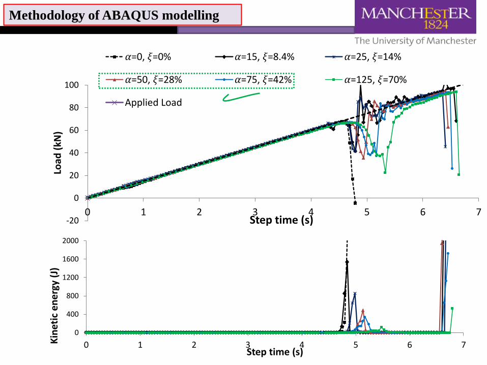
𝛼 = 2 𝜔𝑖𝜉𝑖
𝛽=0
𝛼: Mass proportional damping factor
𝛽:Stiffness proportional damping factor
0
20
40
60
80
100
120
0 100 200 300 400 500 600 700
Ve
rtic
al r
eac
tio
n (
kN)
Middle joint dispalcement (mm)
Test 𝛼=0, 𝜉=0% 𝛼=15, 𝜉=8.4%
𝛼=25, 𝜉=14% 𝛼=50, 𝜉=28% 𝛼=75, 𝜉=42%
𝛼=125, 𝜉=70%
-700
-600
-500
-400
-300
-200
-100
0
0 1 2 3 4 5 6 7
Mid
dle
join
t d
isp
lace
me
nt
(mm
)
Step time (s)
Methodology of ABAQUS modelling
Damping ratio
-20
0
20
40
60
80
100
0 1 2 3 4 5 6 7
Load
(kN
)
Step time (s)
𝛼=0, 𝜉=0% 𝛼=15, 𝜉=8.4% 𝛼=25, 𝜉=14%
𝛼=50, 𝜉=28% 𝛼=75, 𝜉=42% 𝛼=125, 𝜉=70%
Applied Load
0
400
800
1200
1600
2000
0 1 2 3 4 5 6 7Kin
etic
en
erg
y (J
)
Step time (s)
Methodology of ABAQUS modelling
0
20
40
60
80
100
120
0 100 200 300 400 500 600
Ve
rtic
al r
eac
tio
n (
kN)
Middle joint displacement (mm)
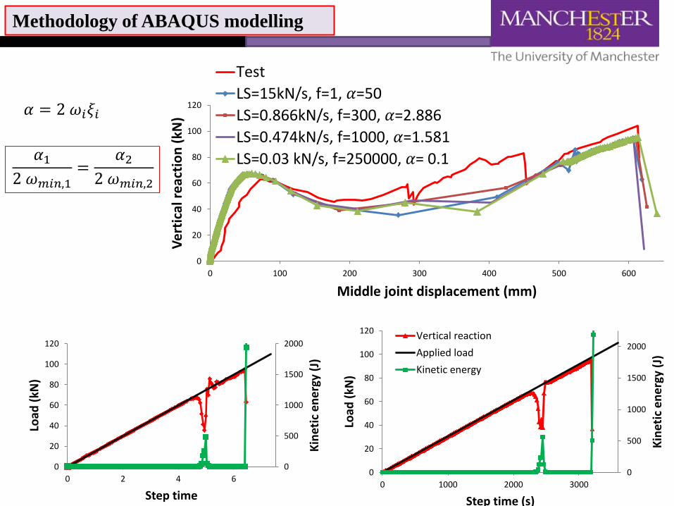
Test
LS=15kN/s, f=1, 𝛼=50
LS=0.866kN/s, f=300, 𝛼=2.886
LS=0.474kN/s, f=1000, 𝛼=1.581
LS=0.03 kN/s, f=250000, 𝛼= 0.1
0
500
1000
1500
2000
0
20
40
60
80
100
120
0 2 4 6
Kin
etic
en
erg
y (J
)
Load
(kN
)
Step time
0
500
1000
1500
2000
0
20
40
60
80
100
120
0 1000 2000 3000
Kin
etic
en
erg
y (J
)
Load
(kN
)
Step time (s)
Vertical reaction
Applied load
Kinetic energy
Methodology of ABAQUS modelling
𝛼 = 2 𝜔𝑖𝜉𝑖
𝛼1
2 𝜔𝑚𝑖𝑛,1=
𝛼2
2 𝜔𝑚𝑖𝑛,2

Sequential coupled thermos-mechanical technique is adopted
Thermal boundary conditions: Eurocode EN 1991-1-2
Steel reinforcement is disregarded in the heat transfer analysis
Minor spalling of normal strength concrete is neglected
Stress-strain relationships with strength/deformation reduction factors at elevated temperatures : EN 1992-1-2. Creep and transient strains are not explicitly considered.
Methodology of ABAQUS modelling
Numerical modelling of RC beams in fire
Heat transfer analysis
Structural analysis

Speeding up the fire loading duration
Effect of speeding up real fire duration on the
numerical behaviour of the RC beam
Loading, heating and specimen details by Dotreppe and Franssen
0
500
1000
0 50 100 150
Tem
pe
ratu
re
(oC
)
Time (min)
Test Abaqus
Predicted and measured reinforcing bar temperature
Methodology of ABAQUS modelling
Lowest natural frequency (𝜔𝑚𝑖𝑛) of
the model =90.6 rad/s
-500
-450
-400
-350
-300
-250
-200
-150
-100
-50
0
0 20 40 60 80 100 120 140
Def
lect
ion
(m
m)
Time (min)
1.2 s / 3600 s
2 s / 3600 s
3s / 3600 s
4 s / 3600 s
Simulation (FRD) / Real
𝐹𝐿𝐷1 × 𝜔𝑚𝑖𝑛,1=𝐹𝐿𝐷2 × 𝜔𝑚𝑖𝑛,2
𝐹𝐿𝐷: fire loading duration

w
Description of the Analysed Beam
Large deflection behaviour of restrained RC beams in fire
Lowest natural frequency (𝜔𝑚𝑖𝑛)
of the model =119 rad/s
Restrained RC beams in fire
f ’c=30MPa
fy=453 MPa

-600
-400
-200
0
200
400
0 100 200 300 400
Axi
al f
orc
e (
kN)
Time (min)
-600
-500
-400
-300
-200
-100
0
0 100 200 300 400
Def
lect
ion
(m
m)
Time (min)
A
B
C
A
B
Large deflection behaviour of restrained RC beams in fire
C
Restrained RC beams in fire
-0.075
-0.05
-0.025
0
0.025
0.05
0.075
0 100 200 300 400
Stra
in (
mm
/mm
)
Time (min)
1324
1
2 3
4 Rupture strain
(tension)
Ultimate strain (compression)

Large deflection behaviour of restrained RC beams in fire
-600
-500
-400
-300
-200
-100
0
100
200
300
0 100 200 300 400
Axi
al f
orc
e (
kN)
Time (min)
-600
-500
-400
-300
-200
-100
0
0 100 200 300 400
Axi
al f
orc
e (
kN)
Time (min)
FLD= 1.5 s / 3600s (f=1, 𝛼=75, CPU time=463 min)
FLD= 3600 s / 3600s (f=5760000, 𝛼=0.03125, CPU time=394 min)
SLD: Fire loading duration f: Mass scaling factor 𝛼:Mass proportional damping factor
0
50
100
150
200
250
300
350
0
20
40
60
80
100
120
140
160
0 2 4 6 8 10
Kin
etic
en
erg
y (J
)
Load
(kN
)
Step time (s)
Vertical reaction forceApplied loadKinetic energy
f=1, 𝛼=75
0
50
100
150
200
250
300
350
0
20
40
60
80
100
120
140
160
0 5000 10000 15000 20000 25000
Kin
etic
en
erg
y (J
)
Load
(kN
)
Step time (s)
𝐹𝐿𝐷1 × 𝜔𝑚𝑖𝑛,1=𝐹𝐿𝐷2 × 𝜔𝑚𝑖𝑛,2
𝛼1
2 𝜔𝑚𝑖𝑛,1=
𝛼2
2 𝜔𝑚𝑖𝑛,2
f=5760000, 𝛼=0.03125

Summary
- ABAQUS/Explicit solver is efficient in solving RC problems that encounters large deformations, material and geometry nonlinearity and temporary instability.
- The simulation methodology is suitable to model RC structural
behaviour at ambient and elevated temperatures. - Speeding up the real loading duration is possible in explicit
solver providing that the inertia effects remain insignificant during the analysis.
- By adopting mass scaling to reduce the simulation time, the real
time scale can be preserved. - If a RC beam is provided with an adequate amount of restraint
at ends, catenary action could develop.

Thank You !
Any
Questions