
NUMERICAL HEAT TRANSFER ENHANCEMENT IN ... Academic Journal ISSN: 2367–7384 Issue 3, pp.87-100,...
14
Eastern Academic Journal ISSN: 2367–7384 Issue 3, pp.87-100, October, 2015 *Corresponding author at: University of Technology, Department “Mechanical engineering” Baghdad, Iraq, E- mail address: [email protected] NUMERICAL HEAT TRANSFER ENHANCEMENT IN SQUARE DUCT WITH INTERNAL RIB Arkan K. AL-Taie* and Mohammad J. Kadham University of Technology Department “Mechanical engineering” Baghdad, Iraq __________________________________________________________________________________ ABSTRACT - This paper presents numerical investigation of heat transfer characteristics of horizontal square duct 500mm long using internal square-circle ribs of 7.5x7.5mm cross section ribs spacing =75mm, with air as the working fluid. Reynolds number= 34.267x10 3 was taken. The steel duct (ASM4120) was subjected to different constant surrounding hot air temperatures (673, 773 and 873K o ). Heat transfer was enhanced by (ΔT=9, 13 and 15K o ) for using ribs at constant surrounding air temperature of (673, 773 and 873K o ) respectively. Increases surrounding hot air temperature increases coolant air temperature at the duct centerline. Increases surrounding hot air temperature having no effect on coolant air velocity. Using ribs enhances fluctuation in coolant air velocity and thus enhances heat transfer rate. All studies where carried out using workbench programFlUENT14.5 by using K-ɛ model. Keywords: cooling enhancement, heat transfer and turbulent flow, internal cooling. _________________________________________________________________________________________ 1. INTRODUCTION Enhancement of heat transfer is an active and important field of engineering research since it increases the effectiveness of heat exchangers. Suitable heat transfer techniques may achieve considerable technical advantages and savings of costs. There are various kinds of available techniques, adopted in many applications as heat exchangers for, automotive, process industry, solar heater etc. [Bergles et al, 1985, Bergles, 1998]. There are many enhancement techniques available. They identified thirteen different techniques, which can be segregated into two groupings: 'passive’ and ‘active’ techniques. Passive techniques employ special surface geometries, like coated surfaces, rough surfaces, extended surfaces or swirl flow devices, fluid additives for enhancement. The active techniques require external power sources, such as mechanical aids, electric or acoustic fields and surface vibration[Webb et al., 2005]. A number of investigations have been conducted using various rectangular channels with 180° turns. Metzger and Sham [Metzger et al., 1986] studied heat transfer effects around smooth rectangular channels with sharp, 180° turns. Carlomagno reported heat transfer measurements performed by means of infrared thermography in an internal flow through a 180° turn in a square channel, which is relevant to the internal cooling of gas turbine blades [Carlomagno, 1996].
Transcript of NUMERICAL HEAT TRANSFER ENHANCEMENT IN ... Academic Journal ISSN: 2367–7384 Issue 3, pp.87-100,...
Eastern Academic Journal ISSN: 2367–7384Issue 3, pp.87-100, October, 2015
*Corresponding author at: University of Technology, Department “Mechanical engineering” Baghdad, Iraq, E-mail address: [email protected]
NUMERICAL HEAT TRANSFER ENHANCEMENT IN SQUAREDUCT WITH INTERNAL RIB
Arkan K. AL-Taie* and Mohammad J. Kadham
University of TechnologyDepartment “Mechanical engineering”
Baghdad, Iraq
__________________________________________________________________________________
ABSTRACT - This paper presents numerical investigation of heat transfer characteristics ofhorizontal square duct 500mm long using internal square-circle ribs of 7.5x7.5mm cross section ribsspacing =75mm, with air as the working fluid. Reynolds number= 34.267x10³ was taken. The steelduct (ASM4120) was subjected to different constant surrounding hot air temperatures (673, 773 and873Ko). Heat transfer was enhanced by (ΔT=9, 13 and 15Ko) for using ribs at constant surroundingair temperature of (673, 773 and 873Ko) respectively. Increases surrounding hot air temperatureincreases coolant air temperature at the duct centerline. Increases surrounding hot air temperaturehaving no effect on coolant air velocity. Using ribs enhances fluctuation in coolant air velocity andthus enhances heat transfer rate. All studies where carried out using workbench programFlUENT14.5by using K-ɛ model.
Keywords: cooling enhancement, heat transfer and turbulent flow, internal cooling._________________________________________________________________________________________
1. INTRODUCTION
Enhancement of heat transfer is an active and important field of engineering researchsince it increases the effectiveness of heat exchangers. Suitable heat transfer techniques mayachieve considerable technical advantages and savings of costs. There are various kinds ofavailable techniques, adopted in many applications as heat exchangers for, automotive,process industry, solar heater etc. [Bergles et al, 1985, Bergles, 1998]. There are manyenhancement techniques available. They identified thirteen different techniques, which can besegregated into two groupings: 'passive’ and ‘active’ techniques. Passive techniques employspecial surface geometries, like coated surfaces, rough surfaces, extended surfaces or swirlflow devices, fluid additives for enhancement. The active techniques require external powersources, such as mechanical aids, electric or acoustic fields and surface vibration[Webb et al.,2005].
A number of investigations have been conducted using various rectangular channelswith 180° turns. Metzger and Sham [Metzger et al., 1986] studied heat transfer effects aroundsmooth rectangular channels with sharp, 180° turns. Carlomagno reported heat transfermeasurements performed by means of infrared thermography in an internal flow through a180° turn in a square channel, which is relevant to the internal cooling of gas turbine blades[Carlomagno, 1996].

Eastern Academic Journal ISSN: 2367–7384Issue 3, pp.87-100, October, 2015
88
Arts et al. investigated the flow and heat transfer in a straight-ribbed cooling channel.They found that the pressure coefficient Cp increases before the ribs and decreases after theribs[Arts et al., 1997].
Waleed Mohammed Abed and Mohammed Abed Ahmed used corrugated channel inthe heat exchanger as these have high heat transfer efficiency and turbulent flow with lowvelocity. Some of the inventors studied flow and heat transfer of corrugated channel[Waleedet a., 2010].TANG Xinyi and ZHU Dongsheng studied the turbulent flow and heat transfer enhancementin ducts or channels with rib, groove or rib-groove tabulators[Tang et al., 2012]. Hu and Shencarried out detailed distributions of internal heat transfer coefficients in a convergent coolingpassage with a staggered array of 45° discrete ribs, and combination of ribs with grooves. Fordiscrete ribs the area average enhancement factors were found to be 3-4 and that of combineddiscrete ribs with grooves were 2.5-3.2 [Rajendra et al., 2009].
In this paper, the effect of fitting (square-circle) ribs in square duct at constantsurrounding hot air temperature on fluid flow and heat transfer will be investigated.
MATHEMATICAL FORMULATION
This study presents a description of the mathematical basis for a comprehensive generalpurpose model of fluid flow and heat transfer from the basic principles of conservation ofmass, momentum, and energy. This leads to the governing equations of fluid flow and heattransfer used for the analysis of steady state, three-dimensional, turbulent and incompressibleflow in addition to thermal performance and cooling effectiveness of pipes with different ribsconfiguration heat exchanger.
GOVERNING EQUATION
The heat-transfer rate is the amount of heat that transfers per unit time. If a hot bar has asurface temperature of To on one side and Ti on the other side, the basic heat-transfer rate dueto conduction can be given by:
TUAQ (1 )
If a hot wall at a temperature To is exposed to a cool fluid at a temperature Ti on oneside, the convective heat-transfer rate can be given by:
ThAQ ( 2 )
The conventional expression for calculating the heat transfer coefficient in fullydeveloped turbulent flow in smooth pipes is the Dittus Boelter. Because of the many factorsthat affect the convection heat-transfer coefficient (h), calculation of the coefficient iscomplex. However, dimensionless numbers are used to calculate (h) for both free convectionand forced convection.
Nu = 0.023Re0.8 Pr0.4 (3)
Eastern Academic Journal ISSN: 2367–7384Issue 3, pp.87-100, October, 2015
89
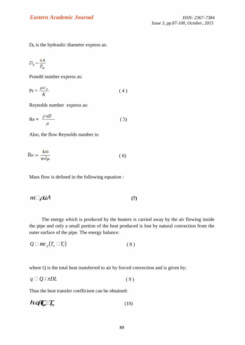
Dh is the hydraulic diameter express as:
Prandtl number express as:
Pr =Kc P ( 4 )
Reynolds number express as:
Re =
uD( 5)
Also, the flow Reynolds number is:
( 6)
Mass flow is defined in the following equation :
(7)
The energy which is produced by the heaters is carried away by the air flowing insidethe pipe and only a small portion of the heat produced is lost by natural convection from theouter surface of the pipe. The energy balance:
iop TTmcQ ( 8 )
where Q is the total heat transferred to air by forced convection and is given by:
DLQq / ( 9 )
Thus the heat transfer coefficient can be obtained:
)/(, bxxw TTqh (10)
uAm

Eastern Academic Journal ISSN: 2367–7384Issue 3, pp.87-100, October, 2015
90
The pressure drop can be determined using:
(11)
The friction factor for the smooth pipe can be calculated by:
2)64.1ln790.0( eo Rf (12)
MESH GENERATION
Volume meshing can be done by two ways of approaches in, structured andunstructured meshing. ANSYS-FLUENT can use grids comprising of tetrahedron orhexahedron cells in three dimensions. The type of mesh selection depends on the applicationas shown in fig. ( 1).
a) Smooth duct
b) Ribbed duct
Fig.(1) Mesh generation: a) smooth duct, b) ribbed duct

Eastern Academic Journal ISSN: 2367–7384Issue 3, pp.87-100, October, 2015
91
2. RESULTS AND DISCUSSION
Temperature Distribution
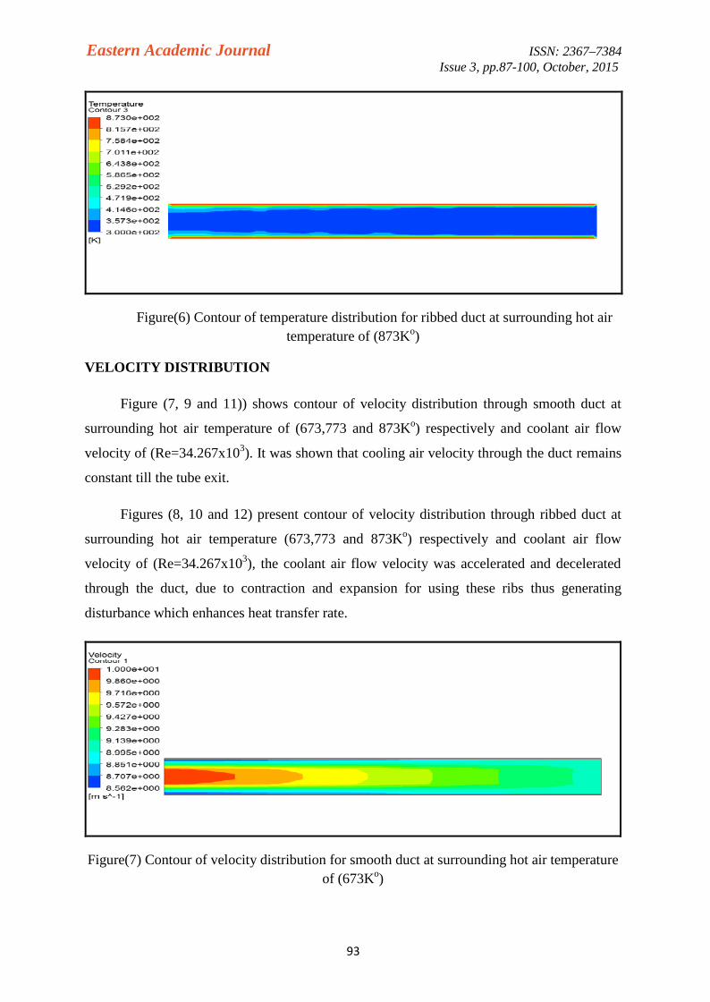
Figures (1, 3 and 5) present contour of coolant air temperature distribution through thesmooth duct at surrounding air temperature (673, 773 and 873Ko) respectively, and coolantair flow velocity of (Re=34.267x10³). Cooling air temperature distribution at tube center lineremains constant till the tube exit and increased near the wall.
Figures (2, 4 and 6) present contour of coolant air temperature distribution throughribbed duct at surrounding air temperature (673, 773 and 873Ko) respectively, and coolant airflow velocity of (Re=34.267x10³). It was shown that at the entrance distance (till to mid) ,temperature at the tube center line was remain un-effected and increasing near the wall ,while the second half show a clear increase in temperature distribution this because ofcirculation generation and hence enhances heat transfer.
Figure(1) Contour of temperature distribution for smooth duct at surrounding hot airtemperature of (673Ko)
Figure(2) Contour of temperature distribution for ribbed duct at surrounding hot airtemperature of (673Ko)

Eastern Academic Journal ISSN: 2367–7384Issue 3, pp.87-100, October, 2015
92
Figure(3) Contour of temperature distribution for smooth duct at surrounding hot airtemperature of (773Ko)
Figure(4) Contour of temperature distribution for ribbed duct at surrounding hot airtemperature of (773Ko)
Figure(5) Contour of temperature distribution for smooth duct at surrounding hot airtemperature of (873Ko)
Eastern Academic Journal ISSN: 2367–7384Issue 3, pp.87-100, October, 2015
93
Figure(6) Contour of temperature distribution for ribbed duct at surrounding hot airtemperature of (873Ko)
VELOCITY DISTRIBUTION
Figure (7, 9 and 11)) shows contour of velocity distribution through smooth duct at
surrounding hot air temperature of (673,773 and 873Ko) respectively and coolant air flow
velocity of (Re=34.267x10³). It was shown that cooling air velocity through the duct remains
constant till the tube exit.
Figures (8, 10 and 12) present contour of velocity distribution through ribbed duct at
surrounding hot air temperature (673,773 and 873Ko) respectively and coolant air flow
velocity of (Re=34.267x10³), the coolant air flow velocity was accelerated and decelerated
through the duct, due to contraction and expansion for using these ribs thus generating
disturbance which enhances heat transfer rate.
Figure(7) Contour of velocity distribution for smooth duct at surrounding hot air temperatureof (673Ko)

Eastern Academic Journal ISSN: 2367–7384Issue 3, pp.87-100, October, 2015
94
Figure(8) Contour of velocity distribution for ribbed duct at surrounding hot air temperatureof (673Ko)
Figure(9) Contour of velocity distribution for smooth duct at surrounding hot air temperatureof (773Ko)
Figure(10) Contour of velocity distribution for ribbed duct at surrounding hot air temperatureof (773Ko)

Eastern Academic Journal ISSN: 2367–7384Issue 3, pp.87-100, October, 2015
95
Figure(11) Contour of velocity distribution for smooth duct at surrounding hot airtemperature of (873Ko)
Figure(12) Contour of velocity distribution for ribbed duct at surrounding hot air temperatureof (873Ko)
Figures (13, 14 and 15) present temperature distribution at the ribbed duct centerline
compared with smooth duct(without ribs) at surrounding hot air temperature of (673, 773
and 873Ko) respectively and coolant air flow velocity of (Re=34.267x10³). Cooling air
temperature for duct with ribs be larger than smooth duct because ribs making wakes which
developed to vortices this lead to increase the heat transfer from the tube wall to the coolant
air i.e. increasing the coolant air temperature , the difference between the inlet and outlet
temperature for smooth and ribbed tube is (0.132Ko) and (9.021Ko) respectively for fig.(13).
Increases surrounding hot air temperature increases coolant air temperature at the duct
centerline.

Eastern Academic Journal ISSN: 2367–7384Issue 3, pp.87-100, October, 2015
96
Figure(13) Coolant air temperature along the duct centerline at surrounding hot airtemperature of(673Ko)
Figure(14) Coolant air temperature along the duct centerline at surrounding hot airtemperature of(773Ko)
Figure(15) Coolant air temperature along the duct centerline at surrounding hot airtemperature of(873Ko)
Eastern Academic Journal ISSN: 2367–7384Issue 3, pp.87-100, October, 2015
97
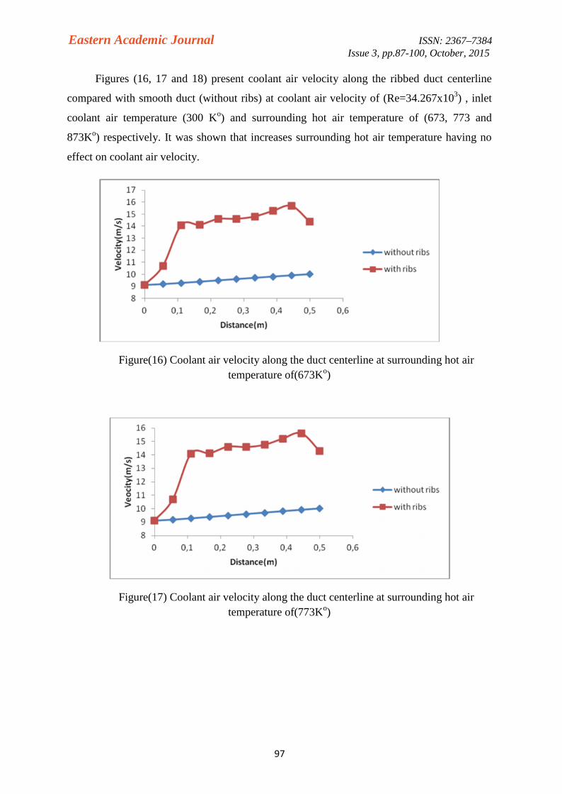
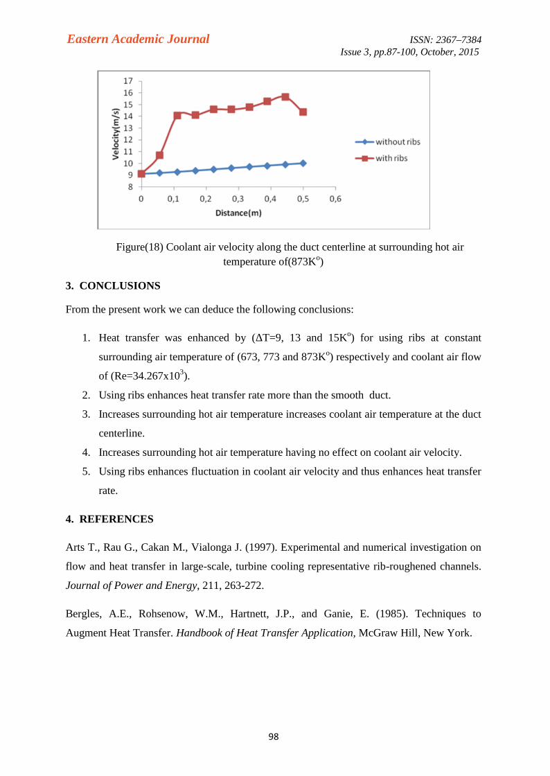
Figures (16, 17 and 18) present coolant air velocity along the ribbed duct centerline
compared with smooth duct (without ribs) at coolant air velocity of (Re=34.267x10³) , inlet
coolant air temperature (300 Ko) and surrounding hot air temperature of (673, 773 and
873Ko) respectively. It was shown that increases surrounding hot air temperature having no
effect on coolant air velocity.
Figure(16) Coolant air velocity along the duct centerline at surrounding hot airtemperature of(673Ko)
Figure(17) Coolant air velocity along the duct centerline at surrounding hot airtemperature of(773Ko)
Eastern Academic Journal ISSN: 2367–7384Issue 3, pp.87-100, October, 2015
98
Figure(18) Coolant air velocity along the duct centerline at surrounding hot airtemperature of(873Ko)
3. CONCLUSIONS
From the present work we can deduce the following conclusions:
1. Heat transfer was enhanced by (ΔT=9, 13 and 15Ko) for using ribs at constant
surrounding air temperature of (673, 773 and 873Ko) respectively and coolant air flow
of (Re=34.267x10³).
2. Using ribs enhances heat transfer rate more than the smooth duct.
3. Increases surrounding hot air temperature increases coolant air temperature at the duct
centerline.
4. Increases surrounding hot air temperature having no effect on coolant air velocity.
5. Using ribs enhances fluctuation in coolant air velocity and thus enhances heat transfer
rate.
4. REFERENCES
Arts T., Rau G., Cakan M., Vialonga J. (1997). Experimental and numerical investigation on
flow and heat transfer in large-scale, turbine cooling representative rib-roughened channels.
Journal of Power and Energy, 211, 263-272.
Bergles, A.E., Rohsenow, W.M., Hartnett, J.P., and Ganie, E. (1985). Techniques to
Augment Heat Transfer. Handbook of Heat Transfer Application, McGraw Hill, New York.
Eastern Academic Journal ISSN: 2367–7384Issue 3, pp.87-100, October, 2015
99
Bergles, A.E., (1998). Some Perspectives on Enhanced Heat Transfer, Second-generation
Heat Transfer Technology. ASME Journal of Heat Transfer, 110, pp. 1082-1096.
doi:10.1115/1.3250612.
Carlomagno G. M.(1996). Quantitative infrared thermography in heat and fluid flow Optical
Methods and Data Processing in Heat and Fluid Flow. IMech. Conference Transaction,
England, 279-290.
Metzger D. E., and Sham M.K.(1986). Heat transfer Around Sharp 180° Turns in Smooth
Rectangular Channels. Journal of Heat Transfer, 108 , 500-506. doi:10.1115/1.3246961.
Rajendra Karwa and B.K. Maheshwari(2009). Heat transfer and friction in an asymmetrically
heated rectangular duct with half and fully perforated baffles at different pitches.
International Communications in Heat and Mass Transfer 36, pp. 264–268.
Tang Xinyi and ZHU Dongsheng(2012). Experimental and Numerical Study on Heat
Transfer Enhancement of a Rectangular Channel with Discontinuous Crossed Ribs and
Grooves. fluid dynamics and transport phenomena Chinese Journal of Chemical
Engineering, 20(2) 220— 230.
Waleed Mohammed Abed and Mohammed Abed Ahmed(2010). Numerical Study Of
Laminar Forced Convection Heat Transfer And Fluid Flow Characteristics In A Corrugated
Channel. Journal of Engineering and Development, Vol. 14, No. 3, 1813-7822.
Webb, R.L., and Kim, N.H. (2005). Principles of Enhanced Heat Transfer, 2nd ed., John
Wiley&Sons, New York.
NOMENCLATURE
A Heat transfer area, m2
Cp Specific heat of air, J/kg.K
Dh Hydraulic diameter, m
f Frictional factor
g Acceleration due to gravity ,m/s2
h Heat transfer coefficient, W/m2. k
K Thermal conductivity, w/m.K
m Mass flow rate, kg/s
Nu Nusselt number, dimensionless

Eastern Academic Journal ISSN: 2367–7384Issue 3, pp.87-100, October, 2015
100
p Pitch of rib, m
Pr Prantdle Number, dimensionless
Q Heat transfer rate, W
Re Reynold number, dimensionless
T Temperature, Ko
U Overall heat transfer coefficient , w/m2.Ko
u Velocity of flow , m/s
b Bulk
c Center
i Inlet
o Outlet
s Surface
w Wall
μ Viscosity of air , N.s/ m2
ρ Density of air, kg/m3