NT-Series Operation Manual - Omron · S User’s manual for each PC...
225
Cat No. V028−E1−1 NT-series Support Tool OPERATION MANUAL
Transcript of NT-Series Operation Manual - Omron · S User’s manual for each PC...

Cat No. V028−E1−1
NT-seriesSupport Tool
OPERATION MANUAL

i

ii

iii
NT-seriesSupport ToolOperation ManualProduced July 1995

iv

v
Safety Precautions:
Read these safety precautions carefully and make sure you understand them before using the program-mable terminal so that you can use it safely and correctly.
Safety Conventions and Their Meanings
This operation manual uses the following conventions and symbols to indicate cautions and warnings inorder to ensure safe use of the PT. The cautions and warnings shown here contain important informationrelated to safety. The instructions in these cautions and warnings must be observed.The conventions used and their meanings are presented below.
Indicates unsafe practices which, if not avoided, could result in death or seri-ous injury.
Example Symbols
WARNING
The triangle indicates a hazard (caution or warning).Details are provided by the contents of the triangle and the accompanying text.The symbol to the left indicates a general hazard.
WARNING
Do not use input functions such as PT touch switches for applications where danger to hu-man life or serious damage is possible, or for emergency switch applications.

vi
OMRON Product ReferencesAllOMRONproducts are capitalized in thismanual. Theword “Unit” is also capitalizedwhen it refers to anOMRON product, regardless of whether or not it appears in the proper name of the product.
The abbreviation “Ch,” which appears in some displays and on some OMRON products, often means“word” and is abbreviated “Wd” in documentation in this sense.
The abbreviation “PC” means Programmable Controller and is not used as an abbreviation for anythingelse.
[Numeral settings]
Each support tool screen displays options for functions to be set. The example to the left shows suchan option, “Numeral setting”.
<Example screens>
This support tool (NT-ZA3PC-V2/ZA3DV-V2) can be used to create screen data for the followingmodels:
NT20M NT20S NT2000M NT600M NT600S NT30 NT30C
NT612G NT610C NT620S NT620C
The screens used for the purposes of explanation in this manual are mainly those of the NT610C.Note that, depending on the model used, the contents of the screen displays may differ somewhatfrom those shown in this manual.
Visual AidsThe following headings appear in the left column of the manual to help you locate different types of in-formation.
Note Indicates information of particular interest for efficient and convenient operationof the product.
1, 2, 3... 1. Indicates lists of one sort or another, such as procedures, checklists, etc.
E OMRON, 1995All rights reserved. No part of this publication may be reproduced, stored in a retrieval system, or transmitted, in anyform, or by any means, mechanical, electronic, photocopying, recording, or otherwise, without the prior written permis-sion of OMRON.
No patent liability is assumed with respect to the use of the information contained herein. Moreover, because OMRONis constantly striving to improve its high-quality products, the information contained in this manual is subject to changewithout notice. Every precaution has been taken in the preparation of this manual. Nevertheless, OMRON assumes noresponsibility for errors or omissions. Neither is any liability assumed for damages resulting from the use of the in-formation contained in this publication.

vii
TABLE OF CONTENTS
SECTION 1Setting Up the Support Tool 1. . . . . . . . . . . . . . . . . . . . . . . .
1-1 Preparing Equipment 2. . . . . . . . . . . . . . . . . . . . . . . . . . . . . . . . . . . . . . . . . . . . . . . . . . . .1-1-1 Equipment to be Prepared 2. . . . . . . . . . . . . . . . . . . . . . . . . . . . . . . . . . . . . . . . . . .1-1-2 Before Starting Preparations 3. . . . . . . . . . . . . . . . . . . . . . . . . . . . . . . . . . . . . . . . .
1-2 IBM PC/AT Preparations 4. . . . . . . . . . . . . . . . . . . . . . . . . . . . . . . . . . . . . . . . . . . . . . . . .1-2-1 Installation Method 4. . . . . . . . . . . . . . . . . . . . . . . . . . . . . . . . . . . . . . . . . . . . . . . .
SECTION 2Basic Operations of the Support Tool 7. . . . . . . . . . . . . . . .
2-1 Starting Up and Exiting the Support Tool 8. . . . . . . . . . . . . . . . . . . . . . . . . . . . . . . . . . . .2-1-1 Start-Up Procedure 8. . . . . . . . . . . . . . . . . . . . . . . . . . . . . . . . . . . . . . . . . . . . . . . .2-1-2 Exit Procedure 9. . . . . . . . . . . . . . . . . . . . . . . . . . . . . . . . . . . . . . . . . . . . . . . . . . . .
2-2 Basic Operating Procedures 10. . . . . . . . . . . . . . . . . . . . . . . . . . . . . . . . . . . . . . . . . . . . . . .2-2-1 Cursors 10. . . . . . . . . . . . . . . . . . . . . . . . . . . . . . . . . . . . . . . . . . . . . . . . . . . . . . . . .2-2-2 Selecting Options 11. . . . . . . . . . . . . . . . . . . . . . . . . . . . . . . . . . . . . . . . . . . . . . . . .2-2-3 Using the Function Keys 11. . . . . . . . . . . . . . . . . . . . . . . . . . . . . . . . . . . . . . . . . . . .2-2-4 Using the Mouse 12. . . . . . . . . . . . . . . . . . . . . . . . . . . . . . . . . . . . . . . . . . . . . . . . . .2-2-5 Using Help Messages 15. . . . . . . . . . . . . . . . . . . . . . . . . . . . . . . . . . . . . . . . . . . . . .2-2-6 Selecting Numbers and Codes 16. . . . . . . . . . . . . . . . . . . . . . . . . . . . . . . . . . . . . . .
SECTION 3Support Tool Operations 19. . . . . . . . . . . . . . . . . . . . . . . . . .
3-1 Using the Support Tool 20. . . . . . . . . . . . . . . . . . . . . . . . . . . . . . . . . . . . . . . . . . . . . . . . . .3-2 Main Menu 21. . . . . . . . . . . . . . . . . . . . . . . . . . . . . . . . . . . . . . . . . . . . . . . . . . . . . . . . . . . .3-3 “Tool Settings” Screen 22. . . . . . . . . . . . . . . . . . . . . . . . . . . . . . . . . . . . . . . . . . . . . . . . . . .3-4 “File List” Screen 26. . . . . . . . . . . . . . . . . . . . . . . . . . . . . . . . . . . . . . . . . . . . . . . . . . . . . . .3-5 “Scr list” Screen 31. . . . . . . . . . . . . . . . . . . . . . . . . . . . . . . . . . . . . . . . . . . . . . . . . . . . . . . .
3-5-1 Functions of the “Scr list” Screen 31. . . . . . . . . . . . . . . . . . . . . . . . . . . . . . . . . . . . .3-5-2 Setting Direct Connection Information 42. . . . . . . . . . . . . . . . . . . . . . . . . . . . . . . . .
SECTION 4Creating Screen Data 49. . . . . . . . . . . . . . . . . . . . . . . . . . . . .
4-1 Initial Editing Screen and Basic Operations 51. . . . . . . . . . . . . . . . . . . . . . . . . . . . . . . . . . .4-1-1 Displaying the “Edit” Screen 51. . . . . . . . . . . . . . . . . . . . . . . . . . . . . . . . . . . . . . . .4-1-2 Basic Operations on the “Edit” Screen 54. . . . . . . . . . . . . . . . . . . . . . . . . . . . . . . . .4-1-3 Environmental Settings (Tool Settings for the “Edit” Screen) 59. . . . . . . . . . . . . . .
4-2 Common Setting Operations 61. . . . . . . . . . . . . . . . . . . . . . . . . . . . . . . . . . . . . . . . . . . . . .4-2-1 Setting Character/Character-String Displays 61. . . . . . . . . . . . . . . . . . . . . . . . . . . .4-2-2 Setting Numeral Displays 63. . . . . . . . . . . . . . . . . . . . . . . . . . . . . . . . . . . . . . . . . . .4-2-3 Specifying the Display Color (NT30C, NT610C Only) 66. . . . . . . . . . . . . . . . . . . .4-2-4 Setting Numeral Memory Tables 68. . . . . . . . . . . . . . . . . . . . . . . . . . . . . . . . . . . . .4-2-5 Setting Character-String Memory Tables 70. . . . . . . . . . . . . . . . . . . . . . . . . . . . . . .4-2-6 Bit Memory Table Setting 72. . . . . . . . . . . . . . . . . . . . . . . . . . . . . . . . . . . . . . . . . . .4-2-7 Setting Words and Bits 75. . . . . . . . . . . . . . . . . . . . . . . . . . . . . . . . . . . . . . . . . . . . .4-2-8 Copying to the Next Input Field (Increment Copy) 77. . . . . . . . . . . . . . . . . . . . . . .

viii
4-2-9 Searching Within a Memory Table 78. . . . . . . . . . . . . . . . . . . . . . . . . . . . . . . . . . . .4-2-10 Batch Changing Bits and Words 79. . . . . . . . . . . . . . . . . . . . . . . . . . . . . . . . . . . . . .
4-3 Creating Fixed Displays 80. . . . . . . . . . . . . . . . . . . . . . . . . . . . . . . . . . . . . . . . . . . . . . . . . .4-3-1 Inputting Characters 80. . . . . . . . . . . . . . . . . . . . . . . . . . . . . . . . . . . . . . . . . . . . . . .4-3-2 Inputting Marks 82. . . . . . . . . . . . . . . . . . . . . . . . . . . . . . . . . . . . . . . . . . . . . . . . . . .4-3-3 Creating Polylines 84. . . . . . . . . . . . . . . . . . . . . . . . . . . . . . . . . . . . . . . . . . . . . . . . .4-3-4 Creating Squares 86. . . . . . . . . . . . . . . . . . . . . . . . . . . . . . . . . . . . . . . . . . . . . . . . . .4-3-5 Creating Polygons 88. . . . . . . . . . . . . . . . . . . . . . . . . . . . . . . . . . . . . . . . . . . . . . . . .4-3-6 Creating Circles/Arcs 90. . . . . . . . . . . . . . . . . . . . . . . . . . . . . . . . . . . . . . . . . . . . . .4-3-7 Creating Fans 92. . . . . . . . . . . . . . . . . . . . . . . . . . . . . . . . . . . . . . . . . . . . . . . . . . . .4-3-8 Tiling 93. . . . . . . . . . . . . . . . . . . . . . . . . . . . . . . . . . . . . . . . . . . . . . . . . . . . . . . . . . .
4-4 Setting Numeral Displays 96. . . . . . . . . . . . . . . . . . . . . . . . . . . . . . . . . . . . . . . . . . . . . . . . .4-4-1 Setting Numeral Displays 96. . . . . . . . . . . . . . . . . . . . . . . . . . . . . . . . . . . . . . . . . . .4-4-2 Modifying Numeral Displays 97. . . . . . . . . . . . . . . . . . . . . . . . . . . . . . . . . . . . . . . .
4-5 Setting Character-String Displays 98. . . . . . . . . . . . . . . . . . . . . . . . . . . . . . . . . . . . . . . . . .4-5-1 Setting Character-String Displays 98. . . . . . . . . . . . . . . . . . . . . . . . . . . . . . . . . . . . .4-5-2 Modifying Character-String Displays 99. . . . . . . . . . . . . . . . . . . . . . . . . . . . . . . . . .
4-6 Setting Lamps 100. . . . . . . . . . . . . . . . . . . . . . . . . . . . . . . . . . . . . . . . . . . . . . . . . . . . . . . . . .4-6-1 Setting Lamps 100. . . . . . . . . . . . . . . . . . . . . . . . . . . . . . . . . . . . . . . . . . . . . . . . . . . .4-6-2 Modifying Lamps 104. . . . . . . . . . . . . . . . . . . . . . . . . . . . . . . . . . . . . . . . . . . . . . . . .
4-7 Setting Touch Switches 105. . . . . . . . . . . . . . . . . . . . . . . . . . . . . . . . . . . . . . . . . . . . . . . . . .4-7-1 Setting Touch Switches 106. . . . . . . . . . . . . . . . . . . . . . . . . . . . . . . . . . . . . . . . . . . . .4-7-2 Modifying Touch Switches 115. . . . . . . . . . . . . . . . . . . . . . . . . . . . . . . . . . . . . . . . . .
4-8 Creating Graphs 117. . . . . . . . . . . . . . . . . . . . . . . . . . . . . . . . . . . . . . . . . . . . . . . . . . . . . . . .4-8-1 Setting Graphs 118. . . . . . . . . . . . . . . . . . . . . . . . . . . . . . . . . . . . . . . . . . . . . . . . . . . .4-8-2 Modifying Graphs 126. . . . . . . . . . . . . . . . . . . . . . . . . . . . . . . . . . . . . . . . . . . . . . . . .
4-9 Creating Input Settings 128. . . . . . . . . . . . . . . . . . . . . . . . . . . . . . . . . . . . . . . . . . . . . . . . . . .4-9-1 Creating Numeral Setting Input Fields 131. . . . . . . . . . . . . . . . . . . . . . . . . . . . . . . . .4-9-2 Creating Character-String Setting Input Fields
(NT30, NT30C, NT610G, NT610C with Ver.3 or Later Only) 134. . . . . . . . . . . . . .4-9-3 Setting Window Displays
(NT30, NT30C, NT610G, NT610C with Ver.3 or Later Only) 135. . . . . . . . . . . . . .4-9-4 Creating Numeric Keys 136. . . . . . . . . . . . . . . . . . . . . . . . . . . . . . . . . . . . . . . . . . . . .4-9-5 Modifying Numeral/Character-String Setting Input Fields 137. . . . . . . . . . . . . . . . . .4-9-6 Changing Orders 139. . . . . . . . . . . . . . . . . . . . . . . . . . . . . . . . . . . . . . . . . . . . . . . . . .
4-10 Extended I/O Settings 140. . . . . . . . . . . . . . . . . . . . . . . . . . . . . . . . . . . . . . . . . . . . . . . . . . . .4-11 Inputting Image and Library Data 141. . . . . . . . . . . . . . . . . . . . . . . . . . . . . . . . . . . . . . . . . .4-12 Editing Memory Tables 143. . . . . . . . . . . . . . . . . . . . . . . . . . . . . . . . . . . . . . . . . . . . . . . . . .4-13 Creating Alarm Lists/Histories 144. . . . . . . . . . . . . . . . . . . . . . . . . . . . . . . . . . . . . . . . . . . . .
4-13-1 Setting Alarm Lists/Histories 145. . . . . . . . . . . . . . . . . . . . . . . . . . . . . . . . . . . . . . . .4-13-2 Modifying Alarm Lists/Histories 147. . . . . . . . . . . . . . . . . . . . . . . . . . . . . . . . . . . . .
4-14 Standalone Settings 149. . . . . . . . . . . . . . . . . . . . . . . . . . . . . . . . . . . . . . . . . . . . . . . . . . . . .4-15 Editing Screen Data 150. . . . . . . . . . . . . . . . . . . . . . . . . . . . . . . . . . . . . . . . . . . . . . . . . . . . .
SECTION 5Creating Marks, Images, and Library Data 159. . . . . . . . . . .
5-1 Marks 160. . . . . . . . . . . . . . . . . . . . . . . . . . . . . . . . . . . . . . . . . . . . . . . . . . . . . . . . . . . . . . . .5-1-1 Mark Creation Procedure 160. . . . . . . . . . . . . . . . . . . . . . . . . . . . . . . . . . . . . . . . . . .5-1-2 Mark Creation Screen 160. . . . . . . . . . . . . . . . . . . . . . . . . . . . . . . . . . . . . . . . . . . . . .5-1-3 Mark Creation Functions 161. . . . . . . . . . . . . . . . . . . . . . . . . . . . . . . . . . . . . . . . . . .

ix
5-2 Images 164. . . . . . . . . . . . . . . . . . . . . . . . . . . . . . . . . . . . . . . . . . . . . . . . . . . . . . . . . . . . . . .5-2-1 Procedure for Image Creation 165. . . . . . . . . . . . . . . . . . . . . . . . . . . . . . . . . . . . . . . .5-2-2 Image Editing Operations 166. . . . . . . . . . . . . . . . . . . . . . . . . . . . . . . . . . . . . . . . . . .
5-3 Library Data 171. . . . . . . . . . . . . . . . . . . . . . . . . . . . . . . . . . . . . . . . . . . . . . . . . . . . . . . . . . .5-3-1 Procedure for Library Data Creation 171. . . . . . . . . . . . . . . . . . . . . . . . . . . . . . . . . .5-3-2 Library Editing Operations 172. . . . . . . . . . . . . . . . . . . . . . . . . . . . . . . . . . . . . . . . . .
SECTION 6Printing Data 175. . . . . . . . . . . . . . . . . . . . . . . . . . . . . . . . . . . .
6-1-1 Things that can be Done Using the Data Printing Function 176. . . . . . . . . . . . . . . . .6-1-2 Printing from the “File Selection” Screen 178. . . . . . . . . . . . . . . . . . . . . . . . . . . . . . .6-1-3 Printing from the “Screen Selection” Screen 180. . . . . . . . . . . . . . . . . . . . . . . . . . . .
SECTION 7Data Communication 183. . . . . . . . . . . . . . . . . . . . . . . . . . . . .
7-1 Preparation and Procedure for Data Communication with the PT 184. . . . . . . . . . . . . . . . . .7-2 Transmitting Data 188. . . . . . . . . . . . . . . . . . . . . . . . . . . . . . . . . . . . . . . . . . . . . . . . . . . . . . .7-3 Receiving Data 190. . . . . . . . . . . . . . . . . . . . . . . . . . . . . . . . . . . . . . . . . . . . . . . . . . . . . . . . .
7-3-1 Data Reception 190. . . . . . . . . . . . . . . . . . . . . . . . . . . . . . . . . . . . . . . . . . . . . . . . . . .7-3-2 Reception of Display History Records 192. . . . . . . . . . . . . . . . . . . . . . . . . . . . . . . . .
APPENDICES 193. . . . . . . . . . . . . . . . . . . . . . . . . . . . . . . . . . .A. Connecting Cable Specifications 193. . . . . . . . . . . . . . . . . . . . . . . . . . . . . . . . . . . . . . . . . . .
Tool Interface Connector Specifications 193. . . . . . . . . . . . . . . . . . . . . . . . . . . . . . . . . . . . .Assembly of Connecting Cables 193. . . . . . . . . . . . . . . . . . . . . . . . . . . . . . . . . . . . . . . . . . .
B. Error Messages 195. . . . . . . . . . . . . . . . . . . . . . . . . . . . . . . . . . . . . . . . . . . . . . . . . . . . . . . . .C. Special Characters 197. . . . . . . . . . . . . . . . . . . . . . . . . . . . . . . . . . . . . . . . . . . . . . . . . . . . . .

x
About this Manual:
This manual describes the basic functions and operation procedures of the NT-series Support Tool andincludes the sections described below.
Please read this manual carefully and be sure you understand the information provided before attemptingto install and operate the NT-series Support Tool.
WARNING Failure to read and understand the information provided in thismanualmay result in personalinjury or death, damage to the product, or product failure. Please read each section in itsentirety and be sure you understand the information provided in the section and related sec-tions before attempting any of the procedures or operations given.
SECTION 1 Setting Up the Support Tool
This section describes how to install the support tool at a personal computer.
SECTION 2 Basic Operations of the Support Tool
This section describes the basic operations that apply to the support tool as awhole, suchas those for start-up, exit, and settings.
SECTION 3 Support Tool Operations
This section describes how to use the basic screens of the support tool, setting options,and the functions of the function keys.
SECTION 4 Creating Screen Data
This section describes how to create the screen data to be displayed by the program-mable terminal (PT).
SECTION 5 Creating a Marks, Images, and Library Data
This section describes how to create special characters and symbols (marks), imagedata, and library data.
SECTION 6 Printing Data
This section describes how to print various types of support tool data, such as screendata and the conditions of use of memory tables.
SECTION 7 Data Communication
This section describes how to transfer screen data created using the support tool to thePT, and how to receive data from the PT.
Appendix This section describes the specifications of the connecting cables, error messages, etc.

xi
Organization of the Manual, and How to Use It:
The related manuals are listed below.
* The final digit of the manual number is the revision code.
[For operating the support tool]
S NT-series Support Tool Operation Manual (V028-E1-1)This manual. . . . . . . . . . . . . . . . . . . . . . . . . . . . . . . . . . . . . . . . . . . . . . . . . . . . . . .
The support tool displays details of operations and procedures on the screen inthe form of “help messages”. Normally, operations can be performed by follow-ing these messages.
However, if you become unsure how to proceed during the course of an opera-tion, or want to check the capabilities of the support tool, refer to this manual.
This manual only describes the operations pertinent to the support tool itself. Itdoes not give detailed explanations of the meanings or effects of the items to beset. For this information, refer to the manuals below.
[For information on PT functions, operations, and restrictions]
S NT20M/NT2000M Programmable Terminal Operation Manual (V001-E1-2)
S NT20S Programmable Terminal Operation Manual (V020-E1-2)
S NT600M Programmable Terminal Operation Manual (V002-E1-2)
S NT600S Programmable Terminal Operation Manual (V022-E1-1)
S NT30/NT30C Programmable Terminal Operation Manual (V034-E1-1)
S NT612G Programmable Terminal Operation Manual (V024-E1-1)
S NT610C Programmable Terminal Operation Manual (V025-E1-1)
S NT620S/NT620C Programmable Terminal Operation Manual (V033-E1-1)
These manuals contain full descriptions of PT functions, operations, and restric-tions. They are organized in a manner that allows screen data to be created byfollowing the User’s Manual for the PT.
[For communication between the PT and host]
S NT-series Direct Connection Operation Manual (V026-E1-1)
The functions that can be executed and the methods for these functions differwidely according to the host interface unit. The user’s manuals for the host inter-face units have been compiled with the PT, the PC, and the communication for-mat taken into consideration.
Anyone familiarwith the functions of the PT can create screen data by referring tothe manual for the host interface unit alone.
[For information on the functions and operations of the PC]
S User’s manual for each PC
When you need information about the operations, functions, etc., of the PC, referto the operation manual for the PC, advanced function unit, or communicationunit being used.

xii
Usable Hardware CombinationsThe combinations of hardware that can be used, and the settings to bemadewiththe support tool, are shown in the table below. Within each box of the table, theupper entry indicates the model of the interface unit (latter part of the model des-ignation only) and the lower entry in parentheses indicates the model of the sys-tem ROM (latter part of the model designation only).
This table shows the basic combinations. Depending on the PT display methodand system configuration, they may not be usable.
PT Model Communication Support Tool “Direct Access” SettingPT Model Communication
Method None Ver.4 Ver.5
NT20S Host − ST121 (-V1) (*1) ST121 (-V1) (*2)
NT − ST121 (-V1) (*1) ST121 (-V1) (*2)
RS ST128 (*2) − −
C200H − ST121 (-V1) (*1) ST121 (-V1) (*2)
NT20M/NT2000M
Host LK201(SMR01-E)
LK201(SMR31-E)
−
RS LK201/LK202(SMR01-E)
− −
C200H LB121(SMR02-E)
LB122(SMR32-E)
−
SYSBUS RT121(SMR01-E)
− −
NT600S Host − ST121 (-V1)/ST211 (-V1)(*2)
ST121 (-V1)/ST211 (-V1)(*2)
NT − ST121 (-V1)/ST211 (-V1)(*2)
ST121 (-V1)/ST211 (-V1)(*2)
RS ST121/ST211 (*2) − −
C200H − LB122 LB122
NT600M Host LK201 (*3)(SMR01-EV1)
LK201(SMR31)
−
RS LK201/LK202(SMR01-EV1)
− −
C200H LB121(SMR02-EV1)
LB122(SMR32)
−
SYSBUS RT121(SMR01-EV1)
− −

xiii
PT Model Communication Support Tool “Direct Access” SettingPT Model Communication
Method Ver.3 Ver.4 Ver.5
NT30/ Host (*2) − ST131/ST141 −NT30C
NT (*2) − ST131/ST141 −
NT612G Host (*4) LK210/LK202(SMR31-V21)
− −
NT (*4) LK201(SMR34-V21)
− −
RS − − −
C200H LB122(SMR32-V21)
− −
BUS/2 − − −
NT610C Host (*4) LK210/LK202(SMR31-V21)
− −
NT (*4) LK201(SMR34-V21)
− −
RS − − −
C200H LB122(SMR32-V21)
− −
BUS/2 − − −
NT620S/ Host (*5) − ST211/ST141 −NT620C
NT (*5) − ST211/ST141 −
(*1) Since the host interface unit/systemROMare incorporated, the PTmodel isindicated. Set “NT20M” as the NT Model with the support tool.
(*2) Since the host interface unit/systemROMare incorporated, the PTmodel isindicated.
(*3) There is also a system ROM for use with the process control function(SMR05).
(*4) When the host link or NT link method of the direct connection function isused, the DAC function (process control function) can be loaded from thesupport tool.
(*5) Since the host interface unit and system ROM are incorporated, the PTmodel is indicated. When using an NT620S, set “NT610G (NT612G)” asthe NT Model with the support tool, and when using an NT620C, set“NT610C”. TheDAC function (process control function) can be loaded fromthe support tool.
Communicationmethods are indicated in the table above using the following ab-breviations:
Host: Host link NT: NT link RS: RS-232C/422
C200H: C200H SYSBUS: SYSBUS

xiv
PT Model and Tool Settings“PT Type” and “Direct Access”
The following combinations of “PT Type” and “Direct Access” settings can bemade in the Tool Settings.
PT Type 20S 20M 600S 600M 30 30C 612G 610C 620S 620C
Direct None f f f f × × × × × ×Access
Ver.3 × × × × × × f f × ×
Ver.4 × f f f f f × × f f
Ver.5 f × f × × × × × × ×
Specifiable Tool Settings
The Tool Settings items that can be set in combination with each “PT Type” and“Direct Access” setting are indicated in the table below.
PT Type 20S 20M 600S 600M
Direct Access None Ver.4 Ver.5 None Ver.4 None Ver.4 Ver.5 None Ver.4
Memory 32KB × × × f f × × × f f
Size64KB f f × f f × × × f f
96KB × × f f f × × × f f
128KB × × × f f f f f f f
256KB × × × × × × × × f f
512KB × × × × × × × × × ×
1024KB × × × × × × × × × ×
Printer f f f f f f f f f f
Sheet Feeder f f f f f f f f f f
Mouse Use f f f f f f f f f f
Communication Mode f f f f f f f f f f
Communication Port f f f f f f f f f f
Work Directory f f f f f f f f f f
Data Directory f f f f f f f f f f
Time [F3] × × × × × × × × × ×
Edit [F4] f f f f f f f f f f

xv
PT Type 30 30C 612G 620S 610C 620C
Direct Access Ver.4 Ver.4 Ver.3 Ver.4 Ver.3 Ver.4
Memory 32KB × × × × × ×Size
64KB × × × × × ×
96KB × × × × × ×
128KB × × × × × ×
256KB × × × × × ×
512KB f f × f × ×
1024KB × × f × f f
Printer f f f f f f
Sheet Feeder f f f f f f
Mouse Use f f f f f f
Communication Mode f f f f f f
Communication Port f f f f f f
Work Directory f f f f f f
Data Directory f f f f f f
Time [F3] f f f f f f
Edit [F4] f f f f f f

xvi
Functions of the Support Tool:
Things that can be done using the support tool
The support tool has the following functions.
Creation of screen data SECTION 4 Creating Screen Data. . . . . . . . . . . . . . . . . . . . . . . . . . . . . . . . . . . .
Creates screen data to be displayed by an NT610C/NT612G.
Besides creating characters and graphics, lamps, touch switches, etc., asscreen data, it is also possible to allocate words for individual elements by usingthe direct connection function.
Management of screen data SECTION 3 Support Tool Operations. . . . . . . . . . . . . . . . . . . . . . . . . . . .
Operations relating to screen data, such as the setting of screen attributes, andcopying and deletion in screen units, are possible.
File management SECTION 3 Support Tool Operations. . . . . . . . . . . . . . . . . . . . . . . . . . . . . . . . . . . . . .
Screen data can be managed in file units.
Data communication with the PT SECTION 7 Data Communication. . . . . . . . . . . . . . . . . . . . . . . . . . . .
The PT can be connected to the support tool for communication of screen datafiles and other types of data.
Printing data SECTION 6 Printing Data. . . . . . . . . . . . . . . . . . . . . . . . . . . . . . . . . . . . . . . . . . . . . . . . . . . . .
Screen data, memory table data, etc., can be printed out at a printer.
Environmental settings SECTION 3 Support Tool Operations. . . . . . . . . . . . . . . . . . . . . . . . . . . . . . . . .
The parameters of the working environment, such as the PT model and datamemory capacity, can be set.
Creating files from screens SECTION 3 Support Tool Operations. . . . . . . . . . . . . . . . . . . . . . . . . . . . .
Screen data can be saved in Microsoft Windows (TM) files (BMP format)
Reading files createdwith other available drawing software SECTION 5 Creating Marks, Images, and Library Data. . . .
Reading BMP files
Image files (BMP format) created using packages such as Microsoft Windows(TM) Paintbrush can be read as data.

xvii
Menu Tree
Main Menu * This comprises the function keys F1 through F10.
File Settings
F1
F2
F3
F4
F5
F6
F7
F8
F9
F10
F1
F2
F3
F4
F5
F6
F7
F8
F9
F10
Copy
Scr list
Prev
Delete
ToolS
Hist.
Tmx.
Rcv.
In.Scr
Title
Next
ROMF1
F10
F1
F2
F3
F10
Copy
Delete
Attrib
Read
Commnt
Co/Ovl
Mark
Next
Check
PrevF3
F4
CoFile
Edit
Tool Settings
Edit
Time
Exit
[Setting Items]PT TypeMemory SizeDirect AccessDirect Macn TypePrinterSheet FeederMouse UseCommunication PortCommunication ModeWork DirectoryData Directory
[Setting Items]Fixed display
Character input (p.80)
Mark display (p.82)
Polyline (p.84)
Square (p.86)
Polygon (p.88)
Circle, arc (p.90)
Fan (p.92)
Tiling (p.93)
Numeral display (p.96)Character-string display (p.98)Lamp setting (p.100)Touch switch setting (p.105)Graph creation (p.117)
Bar graph
Trend graph
Broken-line graph
Input setting (p.128)Data input
Keyboard display
User ten keys
Extended I/O settings (p.140)Image library data display (p.141)Memory table edit
Numeric values
Character-strings
Alarm list setting (p.144)Screen data editing (p.150)
Copy
Move
Delete
Centering
Environmental settings (p.59)
Direct
(p.26) (p.31)
(p.22)
Image & Lib
F4 BchChg
F6 Tmx.
F7 Rcv.

xviii

1
SECTION 1Setting Up the Support Tool
When using the support tool for the first time, the support tool system has to be installed in the personal computer you areusing.
This section describes the environment in which the support tool can be used and the method for installing it in a personalcomputer.
1-1 Preparing Equipment 2. . . . . . . . . . . . . . . . . . . . . . . . . . . . . . . . . . . . . . . . . . . . . . . . . . . . . . . . . .1-1-1 Equipment to be Prepared 2. . . . . . . . . . . . . . . . . . . . . . . . . . . . . . . . . . . . . . . . . . . . . . . .1-1-2 Before Starting Preparations 3. . . . . . . . . . . . . . . . . . . . . . . . . . . . . . . . . . . . . . . . . . . . . . .
1-2 IBM PC/AT Preparations 4. . . . . . . . . . . . . . . . . . . . . . . . . . . . . . . . . . . . . . . . . . . . . . . . . . . . . . .1-2-1 Installation Method 4. . . . . . . . . . . . . . . . . . . . . . . . . . . . . . . . . . . . . . . . . . . . . . . . . . . . . .

2
Preparing Equipment Section 1-1
1-1 Preparing EquipmentThe following equipment and materials must be prepared in order to use the sup-port tool.
1-1-1 Equipment to be Prepared
Software
S NT Series Support Tool (Type NT-ZA3AT-EV2)
This software comes in the form of a 3.5 inch floppy disk.
S DOS
IBM DOS, Ver.5.02 or later version is required.
Hardware
S IBM PC/AT Personal computer
At least 640 Kbytes of main memory is required.
Use an IBM personal computer or 100% compatible.
S At least one floppy disk drive (2HD format type)
There must be one 3.5 inch drive.
S Display
VGA compatible display
When creating screen data for an NT30C/NT610C/NT620C, a color display is re-quired.
S Mouse
Serial mouse or bus mouse
A Microsoft mouse driver is required.
[Common Items]
S Printer
EPSON ESC/P printer (24 pin) or HP LASER Jet.
S Hard disk drive
A hard disk is essential. The available area required for the support tool files anddata area is 2 Mbytes.

3
Preparing Equipment Section 1-1
S Using the EMS (expansion memory)
The EMS must be loaded to the support tool before using it.
DEVICE=EMM386.SYS /F=C000
Equipment Relating to Transfer of Screen Data
S RS-232C connecting cable
For the cable specifications, see Section 7 Data Communication, and the Appen-dix.
Recommended environment
For convenience, you are recommended to use the NT series support tool in thefollowing environment.
Support tool installation site : Hard disk
Work directory (tool settings) : RAM disk
Data directory (tool settings) : Hard disk
For details on “tool settings”, see 3-3 “Tool Settings” Screen (p.22).
Note Back up the data stored in the hard disk in a floppy disk.
1-1-2 Before Starting PreparationsBe sure to make a back-up disk for the support tool system disk and keep the origi-nal somewhere safe.
When making the back-up, ensure that the original disk is write-protected, asshown below:
Write-protection tag
4
IBM PC/AT Preparations Section 1-2
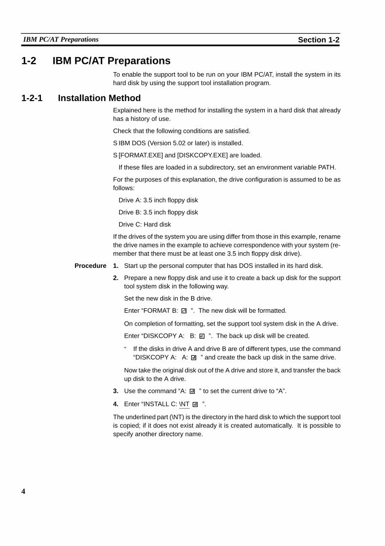
1-2 IBM PC/AT PreparationsTo enable the support tool to be run on your IBM PC/AT, install the system in itshard disk by using the support tool installation program.
1-2-1 Installation MethodExplained here is the method for installing the system in a hard disk that alreadyhas a history of use.
Check that the following conditions are satisfied.
S IBM DOS (Version 5.02 or later) is installed.
S [FORMAT.EXE] and [DISKCOPY.EXE] are loaded.
If these files are loaded in a subdirectory, set an environment variable PATH.
For the purposes of this explanation, the drive configuration is assumed to be asfollows:
Drive A: 3.5 inch floppy disk
Drive B: 3.5 inch floppy disk
Drive C: Hard disk
If the drives of the system you are using differ from those in this example, renamethe drive names in the example to achieve correspondence with your system (re-member that there must be at least one 3.5 inch floppy disk drive).
Procedure 1. Start up the personal computer that has DOS installed in its hard disk.
2. Prepare a new floppy disk and use it to create a back up disk for the supporttool system disk in the following way.
Set the new disk in the B drive.
Enter “FORMAT B: ”. The new disk will be formatted.
On completion of formatting, set the support tool system disk in the A drive.
Enter “DISKCOPY A: B: ”. The back up disk will be created.
" If the disks in drive A and drive B are of different types, use the command“DISKCOPY A: A: ” and create the back up disk in the same drive.
Now take the original disk out of the A drive and store it, and transfer the backup disk to the A drive.
3. Use the command “A: ” to set the current drive to “A”.
4. Enter “INSTALL C: \NT ”.
The underlined part (\NT) is the directory in the hard disk to which the support toolis copied; if it does not exist already it is created automatically. It is possible tospecify another directory name.

5
IBM PC/AT Preparations Section 1-2
If a directory that already exists is specified, the supporttool system will be copied to that directory with no requestfor confirmation. Make sure that no necessary files will beoverwritten.
5. When the message indicating completion is displayed, the installation work isfinished.
D Notes on Installation
S A hard disk with an available capacity of at least 2 Mbytes is required in order toinstall the NT series support tool. If a work directory for the support tool is to becreated on the hard disk, an additional capacity of up to 2 Mbytes will also berequired.
S Start installation after securing sufficient available capacity.
D Available Capacity Required to Run the NT Series Support Tool
S At least 445 Kbytes (455000 bytes) of available main memory capacity is re-quired to run the NT series support software (NT.EXE).
D Checking Available Main Memory Capacity
S Check the available main memory capacity either by using CHKDSK.EXE orMEM.EXE, which are included in the DOS package.
S Input “CHKDSK.EXE” or “MEM.EXE” at the command line to display thememory capacity and other data. If the “usable memory” or “maximumexecutable program size” is 445 Kbytes (455000 bytes) or greater, NT.EXEcan be used.
WARNING

6
IBM PC/AT Preparations Section 1-2

7
SECTION 2Basic Operations of the Support Tool
This section explains the basic operations that apply to the support tool as a whole, such as those for starting up and exiting thesupport tool, and operations using the keyboard and mouse.
When using the support tool, “help messages” which explain the operating procedures are displayed on the screen. Afterbecoming familiar with the basic operations by reading this section, you will therefore be able to use the support tool byfollowing the help messages.
2-1 Starting Up and Exiting the Support Tool 8. . . . . . . . . . . . . . . . . . . . . . . . . . . . . . . . . . . . . . . . . .2-1-1 Start-Up Procedure 8. . . . . . . . . . . . . . . . . . . . . . . . . . . . . . . . . . . . . . . . . . . . . . . . . . . . . .2-1-2 Exit Procedure 9. . . . . . . . . . . . . . . . . . . . . . . . . . . . . . . . . . . . . . . . . . . . . . . . . . . . . . . . .
2-2 Basic Operating Procedures 10. . . . . . . . . . . . . . . . . . . . . . . . . . . . . . . . . . . . . . . . . . . . . . . . . . . . .2-2-1 Cursors 10. . . . . . . . . . . . . . . . . . . . . . . . . . . . . . . . . . . . . . . . . . . . . . . . . . . . . . . . . . . . . . .2-2-2 Selecting Options 11. . . . . . . . . . . . . . . . . . . . . . . . . . . . . . . . . . . . . . . . . . . . . . . . . . . . . . .2-2-3 Using the Function Keys 11. . . . . . . . . . . . . . . . . . . . . . . . . . . . . . . . . . . . . . . . . . . . . . . . .2-2-4 Using the Mouse 12. . . . . . . . . . . . . . . . . . . . . . . . . . . . . . . . . . . . . . . . . . . . . . . . . . . . . . . .2-2-5 Using Help Messages 15. . . . . . . . . . . . . . . . . . . . . . . . . . . . . . . . . . . . . . . . . . . . . . . . . . . .2-2-6 Selecting Numbers and Codes 16. . . . . . . . . . . . . . . . . . . . . . . . . . . . . . . . . . . . . . . . . . . . .
8
Starting Up and Exiting the Support Tool Section 2-1
2-1 Starting Up and Exiting the Support ToolThis section describes the procedure for starting up the support tool once it hasbeen installed in a personal computer.
2-1-1 Start-Up ProcedureThe method for start-up differs a little according to the hard disk drive and directoryin which the support tool is installed.
Procedure 1. Switch on the power supply to the personal computer to start up DOS.
Check that the current drive is the drive for the hard disk in which the supporttool is installed.
If it is not, enter “C: ” to change the current drive. For the underlined part(C:), specify the drive name of the drive in which the support tool is installed.
2. Use the command “CD \NT ” to change the current directory to the directo-ry that contains the support tool. For the underlined part (\NT), specify thename of the directory into which the support tool was copied.
3. Input “NT ”.
The support tool will start up.
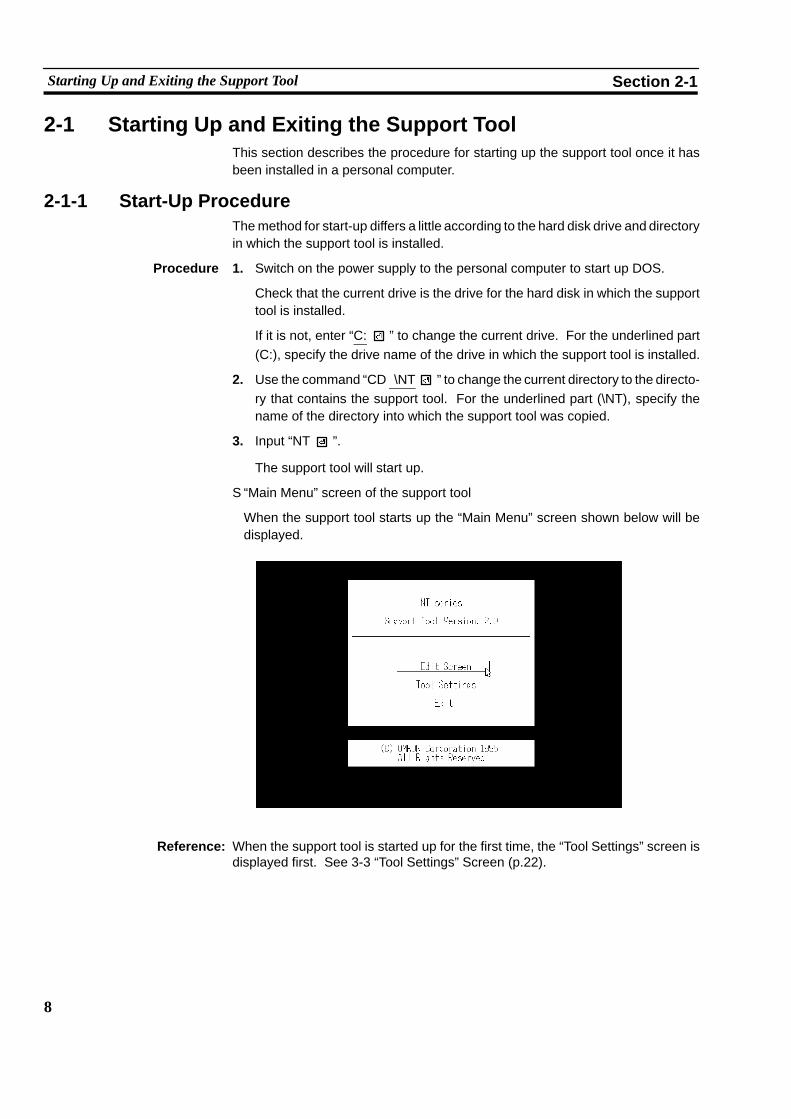
S “Main Menu” screen of the support tool
When the support tool starts up the “Main Menu” screen shown below will bedisplayed.
Reference: When the support tool is started up for the first time, the “Tool Settings” screen isdisplayed first. See 3-3 “Tool Settings” Screen (p.22).

9
Starting Up and Exiting the Support Tool Section 2-1
2-1-2 Exit ProcedureWhen the “Main Menu” screen is displayed, move the cursor to “Exit” using the [�][�] keys and press enter key ( ).
The support tool will be exited and the DOS prompt will be displayed.
After the prompt has appeared, switch the power off.

10
Basic Operating Procedures Section 2-2
2-2 Basic Operating ProceduresThe support tool is a software package that allows the creation of screen data for aPT, and communication with a PT, using simple operations. The user can performthese operations simply by following the help displays that appear on the screen.
Support tool operations can be performed either by using the keyboard or by usinga mouse.
This section explains basic operations such as the selection of menu options andoperation of the mouse.
2-2-1 CursorsThe following types of cursor are displayed on the screen in different circum-stances.
S Bar cursor ( ), box cursor ( ), check box ( )
Used to select options, file names, etc.
This cursor is moved by using the [�][�][� ][� ] keys or the mouse.
S Mouse cursor ( )
This cursor follows the motion of the mouse. When performing operations usingthe mouse, locate this cursor on the required item and click the left mouse but-ton.
S Cup cursor ( )
This cursor is displayed while the support tool is carrying out processing. Whenthe processing is finished it changes into the mouse cursor.
S Enquiry cursor ( )
This cursor is displayed while the support tool is waiting for the input of a reply,such as YES/NO. When this cursor is displayed, press the key (for YES) orthe [Esc] key (for NO).
When using the mouse, press either the left button (for YES) or the right button(for NO). It is also possible to click on icons with the pointed part of the enquirycursor (at its top left corner) (p.12).
S Key input prompt cursor ( )
This cursor is displayed when input is required. When it is displayed, carry outinput from the keyboard or by using the mouse.

11
Basic Operating Procedures Section 2-2
2-2-2 Selecting OptionsWhen performing operations using the support tool it will be necessary to selectmenu options, choices, file names, etc.
Such selections are made by locating the bar cursor on the item to be selected byusing the arrow keys ([�][�][� ][� ] keys) and pressing the key.
Move using [� ] [� ]
Move using [�] [�]
\\
Items which cannot be selected are displayed in red.
2-2-3 Using the Function KeysThe currently available functions and currently selectable options are displayed atthe bottom of the screen. The items displayed correspond to the function keys onthe keyboard. To execute one of the displayed options, press the function key onthe keyboard that corresponds to it.
F1 F2 F3 F4 F5 F6 F7 F8 F9 F10

12
Basic Operating Procedures Section 2-2
2-2-4 Using the MouseIt is possible to perform all the support tool operations by using a mouse.
The left button of the mouse has the same function as the key on the keyboardand right button the same function as the [Esc] button.
Selection or specification of items using the mouse is achieved by clicking one ofits buttons. “Clicking” means pressing the button and releasing it immediately.Clicking with the left mouse button is sometimes called “left clicking” and clickingwith the right mouse button is sometimes called “right clicking”.
S “Mouse Use” specification
Whether the mouse is used or not is specified with the “Mouse Use” option of the“Tool Settings” menu (see p.22). If “No” is specified, the mouse cursor ceases tobe displayed (however, even if “No” is specified, the mouse cursor will be dis-played and will be able to be used when editing image data).
S Selection
Select items by moving the cursor to them and clicking on them.
For example, to select a file, locate the mouse cursor at the intended file name andclick the left mouse button. When the bar cursor has moved, click on the file nameagain with the left button. This will select the file.
Clicking on an input field has the same effect as pressing the key.
S Icon operations
The key marks displayed in the help message area and elsewhere are icons thatcan be actuated with the mouse. Clicking on an icon with the left mouse button willexecute the function represented by that icon.
For example, clicking on the [SPACE] mark displayed on the screen with the leftmouse button will have the same effect as pressing the key.
Click on themark withthe mouse.
Icons

13
Basic Operating Procedures Section 2-2
S Operations on the editing screen
When specifying coordinate positions etc. on the editing screen, the cross-haircursor (intersecting vertical and horizontal lines) is displayed. The cross-hair cur-sor follows the motion of the mouse. To fix a position, click the left mouse button.
Cross-hair cursor
When the cross-hair cursor touches the menu box, the menu box is automaticallycleared from the screen and coordinates are displayed at the top right of thescreen. When the operation with the cross-hair cursor is completed, the menu boxis redisplayed.
Whether or not a menu box is displayed when the cross-hair cursor is displayed isspecified in the “environmental settings” (tool settings for the “Edit” screen).
S Double click
To specify the end points for continuous lines and polygons, double-click themouse. “Double-clicking” means pressing the left mouse button twice in rapid suc-cession.

14
Basic Operating Procedures Section 2-2
S Moving the bar cursor
When screens or display elements are displayed in a list, the bar cursor can bemoved by clicking at entries above or below the current cursor position.
Clicking here causes the barcursor to move downward.
Bar cursor
Clicking here causes thebar cursor to move upward.

15
Basic Operating Procedures Section 2-2
2-2-5 Using Help MessagesThe support tool is provided with “help messages” for each screen: they displaythe key operations that can currently be used, or prompt parameter input or selec-tions.
The key displays in the help message area also function as icons that can be actu-ated using the mouse.
Operate the support tool by following the help messages. There are two types ofhelp message, distinguished on the basis of the screen and function, as indicatedbelow.
S Help messages that display the operating procedure
Usually, as shown in the screen below, the operation keys that can be used withthe current screen, and their details, are displayed in the help message area.
Operation help message
The key, cursor keys, [Page Down], [Page Up], etc., can be used even if theyare not displayed.
S Help messages for parameter input
In cases such as when a function has been selected with a function key, settingsand parameters can be specified in the help message area.

16
Basic Operating Procedures Section 2-2
2-2-6 Selecting Numbers and CodesThe support tool allows simple selection of the following numbers and codes.
S Screen numbers
S Numeral table numbers
S Character-string memory table numbers
S Bit memory table numbers
S Image codes
S Library codes
S Extended I/O input terminal numbers (*)
S Extended I/O output terminal numbers (*)
(*) Only number specification using the [Tab] key can be used for these.
When a screen that displays a list of numbers or codes is displayed, the key opera-tions indicated below can be used:
[Shift] + [�] key : Moves the bar cursor from the position where it is currentlylocated to the previous number or code for which there isdata.
[Shift] + [�] key : Moves the bar cursor from the position where it is currentlylocated to the next number or code for which there is data.
Example:
Assume that the bar cursor is on screen number 6 and there is data only for screennumbers 2, 4, and 10:
[Shift] + [�] key : The bar cursor moves to screen number 4.
[Shift] + [�] key : The bar cursor moves to screen number 10.
If now, while the bar cursor is at screen number 10, [Shift] + [�] is pressed again,the bar cursor will move full cycle to screen number 2.

17
Basic Operating Procedures Section 2-2
[Tab] key : The number/code input field is displayed. When a number ofcode is input and the key pressed, the bar cursor movesto the specified number or code.
Example: Screen number input field

18
Basic Operating Procedures Section 2-2

19
SECTION 3Support Tool Operations
The support tool has the following 5 screens: the “Main Menu” screen, the “Tool Settings” screen, the “File Selection”screen, the “Screen Selection” screen, and the “Edit” screen. This section describes the four screens other than the “Edit”screen.
3-1 Using the Support Tool 20. . . . . . . . . . . . . . . . . . . . . . . . . . . . . . . . . . . . . . . . . . . . . . . . . . . . . . . .3-2 Main Menu 21. . . . . . . . . . . . . . . . . . . . . . . . . . . . . . . . . . . . . . . . . . . . . . . . . . . . . . . . . . . . . . . . .3-3 “Tool Settings” Screen 22. . . . . . . . . . . . . . . . . . . . . . . . . . . . . . . . . . . . . . . . . . . . . . . . . . . . . . . . .3-4 “File List” Screen 26. . . . . . . . . . . . . . . . . . . . . . . . . . . . . . . . . . . . . . . . . . . . . . . . . . . . . . . . . . . .3-5 “Scr list” Screen 31. . . . . . . . . . . . . . . . . . . . . . . . . . . . . . . . . . . . . . . . . . . . . . . . . . . . . . . . . . . . . .
3-5-1 Functions of the “Scr list” Screen 31. . . . . . . . . . . . . . . . . . . . . . . . . . . . . . . . . . . . . . . . . .3-5-2 Setting Direct Connection Information 42. . . . . . . . . . . . . . . . . . . . . . . . . . . . . . . . . . . . . .

20
Using the Support Tool Section 3-1
3-1 Using the Support ToolThe support tool is a software package for creating screen data and transferring itto a PT.
The support tool has five basic screens and on these five screens it is possible tocreate data, and to select various functions and execute them.
The relationships between the screens are shown below.
Support Tool Startup/Exit
Main Menu
“File List” screen
Used to select screen data files.Permits various file-related operations.
“Tool Settings” screen
Used to set the environmentalsettings for the support tool, suchas the PT model used.
Communication with the PTExecute communication ofscreen data etc. with the PT.
PrintPrint screen data, conditions of useof memory tables, etc., at a printer,or store them in files.
“Screen List” screenUsed to select screen data.Screen data attributes can be setand various operations relating toscreen data are possible.
“Edit” screenUsed to create screen data usingcharacters and graphics.
Reference: When the support tool is started up for the first time, the “Tool Settings” screen isdisplayed first.

21
Main Menu Section 3-2
3-2 Main MenuWhen the support tool is started up, the “Main Menu” screen is displayed first.
The items in the main menu have the following functions.
S Edit Screen: Select this item to create or edit screen data. The “File Selection”screen will be displayed and operations relating to screen dataand files will be possible.
S Tool Settings: Used to set the environmental conditions for using the supporttool, such as themodel of the PT used in conjunctionwith the sup-port tool, the image datamemory capacity, and themodel of print-er used. Provided there are no changes, these settings only haveto be set once.
S Exit : Used to exit the support tool. To exit, select this item, wait for theDOS prompt to be displayed and then switch the power off.

22
“Tool Settings” Screen Section 3-3
3-3 “Tool Settings” ScreenThis screen is used to set the environmental settings required to use the supporttool, such as the PT model, capacity of the screen data memory board, and thedirectory in which data is saved.
When using the support tool for the first time, this screen is displayed first. Be sureto set the tool settings in accordance with the model you are using. After this firstsetting, it will not be necessary to set the tool settings again unless there is somechange.
Settings When “Tool Settings” is selected from themainmenu, the “Tool Settings” screen isdisplayed. For details on the permissible combinations of settings, see “PTModeland Tool Settings” (p.xiv) at the beginning of this section.
<“Tool Settings” screen>
\\
S PT Type: Specify the model of PT being used.
Note The specified PT Type setting is different from the actual PTmodel in the followingcases:
NT20S-ST121 (without [-V1]): [NT20M]
NT612G: [NT610G]
NT620S: [NT610G]
NT620C: [NT610C]
S Memory Size: Specify the capacity of the screen data memoryboard installed in the PT.
S Direct Access: Specify the direct connection version. If not usingthe direct connection function, set “Ver.4” for theNT20S, NT20M, NT600S, and NT600M. “NONE”cannot be set for NT612G/610C or NT620C/S.
S Direct Macn Type: Set “NONE” if direct connection is not used. Set“OMRON” if direct connection is used.

23
“Tool Settings” Screen Section 3-3
S Printer: Specify the type of the printer used to print screendata, etc., here.
S Sheet Feeder: Specify whether or not the printer is fitted with asheet feeder here.
S Mouse Use: Specify whether or not amouse is usedwith the sup-port tool, and, if amouse is used, the operationwhenthe mouse is used.
If “Auto movement” is selected, the mouse cursormoves automaticallywhen awindowor other screendisplay for making setting is displayed, speeding upinput and specification operations. If “NoAutoMvmnt” is selected, the mouse cursor does notmove automatically. However, the mouse cursor isdisplayed, and can be used, during image dataediting, even if “Not used” is set.
S Communication Port: Specify the port on the computer to be used to com-municate with the PT. If possible, do not specify thesame port as the one used for the mouse.
S Communication Mode: Set the communication speed for communication ofdata with the PT.
Set “Stndrd” if the conditions for communication areunfavorable due to interference, etc.
S Work Directory: The support tool temporarily creates work files fordata creation and communication, etc. This settingspecifies the directory in which work files can becreated.
S Data Directory: Specify the directory in which created screen datafiles are saved here.
Reference: S The NT series support tool is compatible with all OMRON PT models, allversions of the direct connection function (Ver.3, Ver.4, Ver.5), and thecommunicationmethods other than direct connection. The support tool displaysand selectable functions differ according to the settings made for “PT Type”,“Direct Access”, and “Direct Macn Type”.
S For details on the direct connection function, refer to the user’s manual for therelevant host interface unit.
S The specified “PT Type”, “Memory Size”, “Direct Access”, and “Direct MacnType”, are displayed on each screen as shown below.
24
“Tool Settings” Screen Section 3-3
Example
File Selection screen when “612G”, “512B”, and “Ver.3”, respectively, have beenset for these items.
File List NT610G−V3−O 512KB
PT Type (PT model name)Direct Access (Direct connection version)
V3 = “Ver.3”V4 = “none”* or “Ver.4”V5 = “Ver.5”
Direct Macn Type (Direct model)
O = PC made by OMRONNoting displayed = Direct connection
not used
Memory size
*: For “20M”, “20S”, “600M”, “600S”
Functions of the function keys
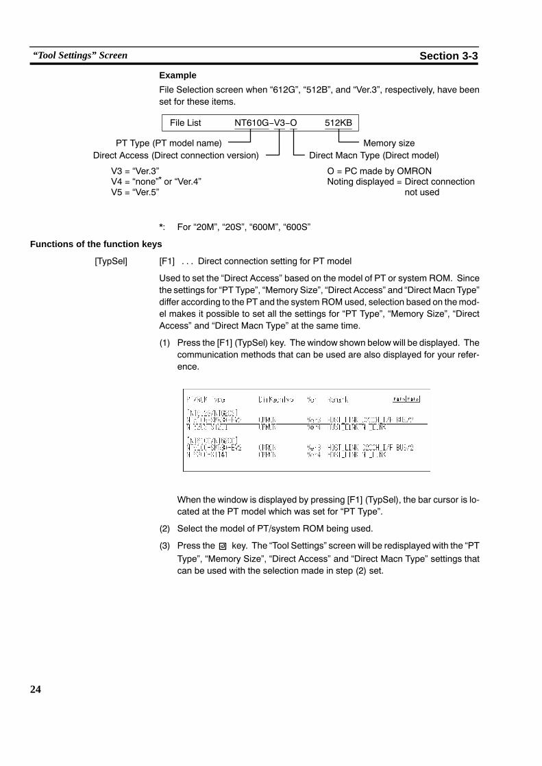
[TypSel] [F1] Direct connection setting for PT model. . .
Used to set the “Direct Access” based on the model of PT or system ROM. Sincethe settings for “PT Type”, “Memory Size”, “Direct Access” and “Direct Macn Type”differ according to the PT and the system ROM used, selection based on themod-el makes it possible to set all the settings for “PT Type”, “Memory Size”, “DirectAccess” and “Direct Macn Type” at the same time.
(1) Press the [F1] (TypSel) key. The window shown belowwill be displayed. Thecommunication methods that can be used are also displayed for your refer-ence.
When the window is displayed by pressing [F1] (TypSel), the bar cursor is lo-cated at the PT model which was set for “PT Type”.
(2) Select the model of PT/system ROM being used.
(3) Press the key. The “Tool Settings” screen will be redisplayed with the “PTType”, “Memory Size”, “Direct Access” and “Direct Macn Type” settings thatcan be used with the selection made in step (2) set.

25
“Tool Settings” Screen Section 3-3
[Time] [F3] PT time setting. . .
Used to make the time setting for the PT. The time function can be used with theNT30, NT30C, NT612G, NT610C, NT620S, NT620C.
(1) Connect the PT and the support tool (see Section 7 Data Communication).
(2) Press the [F3] (Time) key.
(3) To change the current time, enter the time on the screen.
(4) Set the PT to the “Transmit Mode”.
(5) Press the key: the time data will be sent and set in the PT.
" It is also possible to receive the time set in the PT and set it. Press the [F1](receive) key with the time setting screen displayed.
[Edit] [F4] Tool settings for the “Edit” screen (environmental settings). . .
Used to set the “Edit” screen settings, such as grid display and “snap ON” setting.
These settings can also be made by selecting SET ENV on the initial editingscreen. For the details of these settings see “Environmental Settings” (p.59).
Quitting tool setting
S Press key twice: the support tool will be set in accordance with the detailsdisplayed on the screen and the display will return to the main menu.
S Press the [Esc] key to return to the main menu without making any settings.

26
“File List” Screen Section 3-4
3-4 “File List” ScreenWhen the “Edit Screen” option is selected from the main menu, the “File List”screen is displayed.
In support tool terminology, an assemblage of screen data is called a “file”.
Actually, each “file” comprises four or five files with different extension names (thenumber of files per “file” depends on the “tool settings”).
Settings On the “File List” screen, besides creating and selecting files, it is also possible toperform functions such as data communication with the PT.
<“File List” screen>
(a) (b) (c)
(d)
(f)
(e)
(g)
(a) PT model name: This is the PT model and direct connection ver-sion number set in the “Tool Settings”. The final 0indicates direct connection. Even if direct connec-tion is not used, the version is displayed as “V4”when using an NT20M, NT20S, NT600M, orNT600S.
(b) PT memory size
(c) Name of task currently being executed
(d) Help message area: Displays a guide to operation and allows parame-ter input.
(e) File name: The file names are indicated in this column. If thebar cursor is located on a file name and thekey pressed, the “Screen Selection” screen will bedisplayed. To create a new file, select“NEW_FILE”.
(f) Title: This is a comment that indicates the contents of afile. It is input when the file is saved.

27
“File List” Screen Section 3-4
(g) File information: The NT model, direct connection version, directconnection indication, and file size for the file atwhich the bar cursor is located are displayed here.Even if direct connection is not used, the versionis displayed as “V4” when using an NT20M,NT20S, NT600M, or NT600S.
The support tool allows the creation of up to 200 “files” (the numbermay be smallerthan this due to restrictions on the number of files per DOS directory). If the re-quired file is not displayed on the screen, screens earlier and later in the sequencecan be displayed by using the [Page Down] and [Page Up] keys, or icons.
Depending on the direct connection version of the model used, it may or may notbe possible to use certain files.
Files that cannot be used are displayed in red.
To use more than 200 files, create another directory. The data directory can bechanged by using the “Tool Settings” option.
All the files in the specified data directory are displayed.
The files that correspond to the “PT Type” and “Direct Access” set in the “ToolSettings” are first in the order of display. The other files are displayed in the fol-lowing order: 20M, 20S, 600M, 600S, 612G, 610C, 30, 30C; files correspondingto the same model are displayed in order of direct connection version.
It is possible to read files set using other models but you are advised to check thedetails of the file information displayedwhen the file is specified before reading it.It is also possible to read files created using previous support tool versions.
Returning to the main menu
To return to the main menu, press the [Esc] key.
Functions of the Function Keys
[Copy] [F1] Copy file. . .
Used to copy the contents of a file to another file (copying in support tool “file”units).
(1) Press the [F1] (copy) key.
(2) Select the file to be copied.
(3) Input the file name and title of the copy destination and press the key.
" If [F1] (drive) is now selected, the file can be copied to the directory of anotherdrive.
[Delete] [F2] Delete file. . .
Used to delete unnecessary files (deletion in support tool “file” units).
(1) Locate the bar cursor at the file to be deleted and press the [F2] key.
(2) Check the file name and then press the key: the file will be deleted.

28
“File List” Screen Section 3-4
[Print] [F3] Print data. . .
Used to print out files, information relating to screen data, character-strings, theconditions of use of numeral tables, etc.
See Section 6 “Printing Data”.
[Tools] [F4]] Tool settings. . .
Displays the “Tool Settings” screen.
Used to change the support tool environment during file operations.
For details of the setting operation, see 3-3 “Tool Settings” Screen (p.22).
[Hist.] [F5] Receive display history registration data. . .
Used to read display history registration data registered in the PT and save it in afile.
This file is a text style of DOS format file and is therefore different style from thefiles in which screen data is saved.
See Section 7 “Data Communication”.
[Tmx.] [F6] Send data to the PT. . .
Establishes a connection with the PT, sends created data to it in file units andwrites it to the image data memory. The types of data that can be sent are screendata, character-string memory table and numeral table data, system memorydata, mark data, image data, library data, and direct information.
See Section 7 “Data Communication”.
[Rcv.] [F7] Receive data from the PT. . .
Used to receive data registered in the PT in file units. The types of data that can bereceived are screen data, character-string memory table and numeral table data,system memory data, mark data, image data, library data, and direct information.
See Section 7 “Data Communication”.
[In.Scr] [F8] Set system memory. . .
Used to set the screen number and PT statuses at startup that are displayedwhenthe PT is started up.

29
“File List” Screen Section 3-4
The following items can be set:
Initial screen Number of the screen data displayed when thePT is started up.
(Invalid when direct connection is used)
Supported by allNT models
Key input buzzer ON/OFF status of key input sound. Supported byC
Buzzer Buzzer sound ON/OFF or ON only when anerror occurs.
NT30, NT30C,NT612G, andNT610C only.
Resume function ON/OFF status of the “resume” function.NT610C only.
Alarm output ON/OFF status of alarm output.
Backlight OFF(prevention ofafterimage)
This is an afterimage prevention function whichautomatically switches off the backlight (ormakes the display blank). The availablesettings are to switch the backlight off after atime lapse of 10 minutes/1 hour, or “off”. Withan LED screen, this function switches thebacklight OFF. With an EL screen, it makes thescreen blank.
Printer: Type of printer connected to the PT: EPSONEsc/P printer (24 pin) or HP LASER Jet.
Print way Printing method used when printing a screendisplayed on the PT: color or grayscale (onlyvalid when using NT30C and NT610C).
Numeral tables The number of numeral tables: 512 or 1000 (ifreduced to 512, the memory capacity availablefor screen data is increased by 4880 bytes).
String tables The number of character-string memory tables:256 or 1000 (if reduced to 256, the memorycapacity available for screen data is increasedby 29760 bytes).
Alarm fast I/O Processing method when the maximum numberof alarm instances (256) is exceeded whenusing the alarm history.
“Yes” Old records are deleted as new onesare registered.
“No” The registration of new history recordsis prevented.
On completion of setting, press the key.
30
“File List” Screen Section 3-4
[Title] [F9] Change file title
Used to change the titles of files for which titles have been set.
(1) Locate the bar cursor at the file whose title is to be changed and press the [F9](Title) key.
(2) Enter the new title and press the key.
[Next] [F10] Display next function keys. .
Pressing this key changes the function key display to the next set of function keys.
The functions of these function keys are explained below.
[ROM] [F1] Data communication with P-ROM writer. . .
Used to communicate with a P-ROM writer in order to create or modify EP-ROMsfor image memory boards.
[Prev] [F10] Display previous function keys. .
Pressing this key changes the key display to the previous set of function keys.
31
“Scr list” Screen Section 3-5
3-5 “Scr list” ScreenThe “Scr list” screen is displayed when a file to be edited is selected from the “Se-lect File” screen, or when NEW_FILE is selected.
3-5-1 Functions of the “Scr list” ScreenSettings Besides specifying the screen number for which screen data is to be created, vari-
ous other operations and settings relating to screen data are possible on thisscreen, for example the setting of attributes for screen data and reading of datafrom other files in screen units.
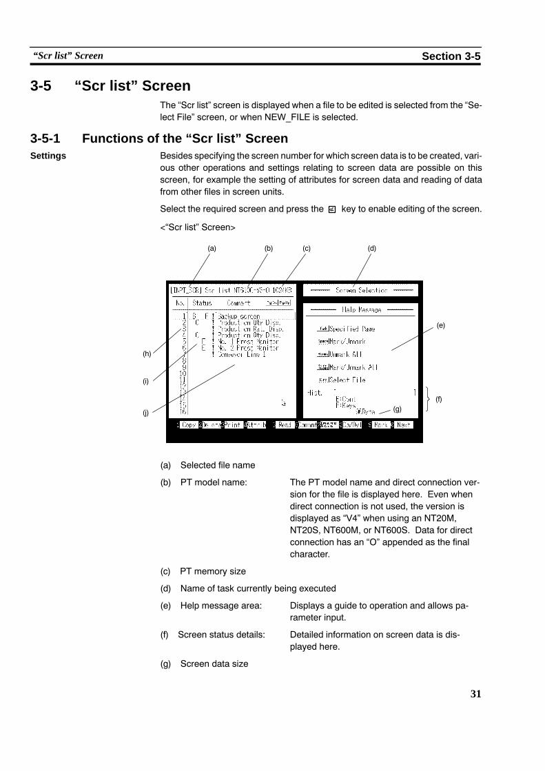
Select the required screen and press the key to enable editing of the screen.
<“Scr list” Screen>
(h)
(b) (c) (d)
(i)
(j)
(a)
(e)
(g)(f)
(a) Selected file name
(b) PT model name: The PT model name and direct connection ver-sion for the file is displayed here. Even whendirect connection is not used, the version isdisplayed as “V4” when using an NT20M,NT20S, NT600M, or NT600S. Data for directconnection has an “O” appended as the finalcharacter.
(c) PT memory size
(d) Name of task currently being executed
(e) Help message area: Displays a guide to operation and allows pa-rameter input.
(f) Screen status details: Detailed information on screen data is dis-played here.
(g) Screen data size

32
“Scr list” Screen Section 3-5
(h) Screen number: The support tool manages screen data underscreen numbers. Screen data can be createdunder the screen numbers shown in the tablebelow.
NT Model Setting Usable Screens
20S 1 to 500
20M 1 to 250
600S, 600M 1 to 1000
30, 30C, 612G, 610C 1 to 2000
The previous and next pages can be displayedby using the [Page Up] and [Page Down] keys.
The bar cursor can be moved to the previousand next screen number for which there is databy using [Shift] + [�] and [Shift] + [�].
The “No.” column is displayed by pressing[Tab] key.
(i) Screen status, attribute: In the “Status” column, the presence/absenceof screen data and the set attribute are dis-played in symbolic form.
More detailed information relating to these in-dications is displayed in the “Screen Status”area at the bottom right of the screen.

33
“Scr list” Screen Section 3-5
Symbol “Screen Status”Information Meaning
(Blank) (No data) No data has been created for this number.
! (Data exists) There is data for this number.
A A: Cont Parent screen of continuous screens
A A: Ovlp Parent screen of overlapping screens
B B: Cont Buzzer attribute (continuous tone)
B B: Long Buzzer attribute (intermittent long tones)
B B: Shrt Buzzer attribute (intermittent short tones)
C C: Hist Display history attribute
D D: Touch Bit input (touch switch)
D D: Fn key Bit input (function key)
E E: Alrm Alarm attribute
F F: Keys “Keypad” ten keys are set by the user.
G G: Ext NT20M, NT30 : Red backlight or flash-ing backlight
NT20S : Flashing backlightNT30C : Background color or
flashing backlightNT610C, NT620C : Background color
(j) Comment: This is a comment assigned to the screendata. It is set when the screen data is saved.
It can be changed using the [F6] (Commnt)key.

34
“Scr list” Screen Section 3-5
<Screen numbers and their applicability>
When the NT Model setting is “30”, “30C”, “610G (612G)”, or “610C”, somescreens are earmarked for special applications, as shown below. When the NTModel setting is not one of these, only “0” (clear screen display) is valid and all oth-er screens are user screens.
Screen No. Application User Editing Remarks
0 Screen display OFF × Specified in order to switch the screen dis-play off.
1 to 1899 User screens f Can be used without restriction
1900 to 1979 Window (keyboard) screenf
Can be used as a window (keyboard) screencalled to overlay another screen.Can also be used as a normal screen.
1980 to 1996 Reserve screens for expan-sion functions f
If data is registered for these screens, treat-ing them as normal screens, the registereddata takes priority.
19971998
Display history screens1997: Order or occurrence1998: Order of frequency
Only when using Ver.3 or a later version ofthe direct connection function (necessary tocreate scroll keys).
1999 “Connecting Host” screenf
If no data is registered, the “ConnectingHost” screen set by the system is displayed.
2000 “Host Error” screen
f
If no data is registered, the “Host Error”screen set by the system is displayed.(Used as a user screen in the case of theNT30, NT30C, NT620S, NT620C)
f: Possible : Only the area outside the display history display area can be edited. ×: Not possible
<Using the marking function>
When, for example, deleting screen data, a number of screens can be handledtogether by using the marking function. All marked (*) screen data is taken as theobject of the executed operation, regardless of the location of the bar cursor. In acopy operation, the screen data at the location of the bar cursor is copied to allscreen numbers marked by (*). This is useful when creating very similar screens.
[Space] key: Marks the selected screen data. If the data is alreadymarked,the mark is deleted.
[Home] key: Deletes all marks.
[Shift] + [Home]: Deletes themarks of all marked screen data andmarks all un-marked screen data.

35
“Scr list” Screen Section 3-5
To perform an operation all screens except a specified screen (or screens), usethe following procedure:
Example: Deleting all screen numbers except screens 1 to 3.
1. Clear all marks by pressing the [Home] key.
2. Mark screens 1 through 3 by pressing the [Space] key.
3. Press [Shift] + [Home].
All screen numbers except 1 through 3 will be marked.
4. Delete the screen data by pressing [F2] (Delete).
<Saving and quitting screen data files>
Pressing the [Esc] key while the “Screen Selection” screen is displayed quitsscreen creation. There are two types of quitting: quitting after saving the file, andquitting without saving the file.
key: Press after inputting the file name and comment to save the fileand return to the “File Selection” screen.
[Space] key: Used to return to the “File Selection” screen without saving thefile.
[Esc] key: Used to abort quitting and continue screen selection.
Functions of the Function Keys
[Copy] [F1] Copy screen data. . .
Used to copy screen data to another screen number.
(1) Locate the bar cursor at the screen data to be copied, and press the [F1](Copy) key.
(2) Input the copy destination screen number and comment and press thekey.
" It is also possible to batch copy all marked screen numbers.
[Delete] [F2] Delete screen data. . .
Used to delete unnecessary screen data.
(1) Locate the bar cursor at the screen data to be deleted and press the [F2] (De-lete) key.
(2) Press the key.
" It is also possible to batch copy all marked screen numbers.
[Print] [F3] Print data. . .
Used to print out screen images and the numbers of lamps and touch switches at aprinter.
See Section 6 “Printing Data”.

36
“Scr list” Screen Section 3-5
[Attrib] [F4] Set attribute. . .
Used to set screen attributes. Setting is accomplished by making selections in theHelp Message area. The following attributes can be set.
Attribute Possible Settings“NT Model” Setting
RemarksAttribute Possible Settings20S 20M 600S 600M 30 30C 610G 610C
Remarks
BuzzerNone, Cont (continuous sound),Long (long intermittent sounds),Shrt (short intermittent sounds)
� � � � f f f f
�: Continuoussound,Intermittentsounds
History No, Yes f f f f f f f f
Bit InOff, Touch SW (touch switch),Extd I/O
�/× f/× �/× f/× −/× −/× f/× f/×
Direct connectionused/not used
�: F keys cannotbe set.
Alarm
No, Yes × f × f × × � �
�: Cannot beused withNT620S/NT620C
Keypad System, User f f f f f f f f
Back light Lit, Flash f f × × f f − −
Bklt Col White, Red × f × × f × − −
Back Col Screen background colors − − − − × f × f
f: Possible �: Partly possible (some restrictions apply). ×: Not possible, −: No display
For details on each attribute, refer to the Operation Manual for the PT.
The attributes of the parent screen are used in the case ofcontinuous screens and overlapping screens. Screenattributes set for child screens are invalid.
Batch setting of attributes for all marked screen numbers is possible.
[Read] [F5] Read screen data. . .
Used to read screen data and memory table data from other files.
However, the data of files displayed in red cannot be read as it is: data conversionis necessary (see Section 8).
(1) Press the [F5] (Read) key.
(2) Select the file whose data is to be read and press the key.
" Pressing the [F1] (Drive) key allows the specification of a file in another drivedirectory. Only files for which the “Direct Access” setting is the same can bespecified.
WARNING

37
“Scr list” Screen Section 3-5
(3) The procedure after this point differs according to the type of data: see thescheme below. Specify the data to be read, the reading source and readingdestination by following the directions on the screen in order to read the data.
Confirmation ofreading execution
information ofdata to be read
Screen dataReading sourcescreen information
Reading destinationscreen information
Overwrite/insertinformation
Read executionconfirmation Execution of reading
Mark dataAll/part?
AllRead executionconfirmation Execution of reading
Part
Reading sourcerange information(start point, end point)
Read positioninformation
Read executionconfirmation Execution of reading
Execution of reading
Numeral tableCharacter-string tableDirect connection informationI/O commentBit memory table
Read executionconfirmation
All/part?
AllRead executionconfirmation Execution of reading
Part
Image dataLibrary data
Reading sourcecode information
Reading destinationcode information Execution of reading
*5 *5
*3*2 *2
*1
*4
(*1) The following restrictions apply to the data that can be read.
Image data: “30”, “30C”, “610G”, and “610C” only.
Library data: “30”, “30C”, “610G”, and “610C”, Ver.3 or later only.
Direct connection information:When direct connection used only.
I/O comment:When direct connection used only
Bit memory table:“30”, “30C”, “610G”, and “610C”, Ver.3 or later only.
(*2) When the [Tab] key is pressed and a screen number input, the bar cursorshifts to the specified screen.
(*3) Overwrite: If data already exists at the destination it is overwritten (theoriginal data is cleared).
Insert: If data already exists at the destination the data is read into thefile without clearing the original data.
38
“Scr list” Screen Section 3-5
(*4) When direct connection is used and reading of a numeral memory table,character-string memory table, or bit memory table is specified, confirma-tion of whether or not the direct connection information is read is displayed.
(*5) S Image data is selected from codes FE20 through FEFF.
S Library data is selected from FA20 through FAFF, FB20 through FBFF,FC20 through FCFF, FD20 through FDFF.
S Use [Shift] + [�] or [Shift] + [�] to move the bar cursor to the previous ornext code for which there is data.
S The bar cursor can bemoved to a specified code by pressing the [Tab] keyand inputting the code.
It is possible to continue reading more data from the same file.
To quit data reading, press the [Esc] key; the display will return to the “ScreenSelection” screen.
[Commnt] [F6] Change comment. . .
Used to change the comments assigned to screen data.
(1) Locate the bar cursor at the screen number whose comment is to be changedand press the [F6] (Commnt) key.
(2) Input the new comment and press the key.
It is possible to change the comments for a number of screen numbers in abatch by marking the screen numbers. However, this only applies to screennumbers for which data already exists.
[Image & Lib] [F7] Edit Image/library data. . .
Used to create and modify image library items.
Editing of images and library data is only possible with the NT30, NT30C,NT612G, and NT610C.
See Section 5 “Creating a Mark Image Library”.
[Co/Ovl] [F8] Continuous screen & overlapping screen setting. . .
Used to specify continuous screens and overlapping screens.
(1) Locate the bar cursor at a screen number for which there is no data and pressthe [F8] (Co/Ovl) key.
" If a number for which there is data is specified, a message asking whether ornot the data is to be cleared is displayed.
(2) Select either “Cont Scr” or “Ovlp Scr” and press the key.
The set screen will become the parent screen.
(3) Set the child screens by following the help messages.
" Up to 8 child screens can be set in the case of both continuous screens andoverlapping screens.
" Only one numeral setting screen can be set as a child screen.

39
“Scr list” Screen Section 3-5
[Mark] [F9] Mark creation. . .
Used to create and modify marks.
See Section 5 “Creating a Mark, Images, and Library Data”.
[Next] [F10] Display next function keys. .
Pressing this key changes the function key display to the next set of function keys.
Direct connection not used
Ver.1 to Ver.4 used
For an explanation of the function of each function key, see the following.
[Check] [F1] Check on continuous screens/overlapping screens. . .
Used to check if there is any abnormality in the relationship between the parentand child screens of continuous screens and overlapping screens.
(1) Select the file to be selected on the “File List” screen.
(2) Press the [F10] (Next page) key and then press the [F1] (Check) key.
(3) Set whether or not the results are to be output at a printer and execute thecheck.
The results of the check are displayed in the following form.
No. Error Details
No. : The parent screen number is displayed here.
Error : If an error is found, its details are displayed.
Error Type Cause
Prnt A screen set as child screen has been specified as the parent screen for anothercontinuous screen or overlapping screen.
Keys Overlapping screen There are two or more child screens for which a numeralsetting has been made (when carrying out system setting).
Continuous screen There is a child screen for which a numeral setting has beenmade.
Num Overlapping screen In direct connection, the total of the numbers the followingfunctions exceeds the maximum number that can be set.
Number of functions settable:
Numeral displays + graphs + numeral settings = Max. 1024
Attr Overlapping screen The “keypad attribute” is different for the parent screen andchild screens.

40
“Scr list” Screen Section 3-5
Details: The numbers of the child screens that make up the overlappingscreen or continuous screen are displayed.
If there is an error, the relevant screen number is underlined.
If screen numbers in the range 1900 to 1979 are specified as parent screens,“No.” will be displayed in red. These screens cannot be used as windowscreens.
[Table] [F2] Edit table (when not using direct connection). . .
Used to write data to, and change the data in, character-string memory tables andnumeral memory tables.
(1) Press the [F2] (Table) key.
(2) Select the character-string memory table or numeral memory table and pressthe key.
(3) Edit the contents of the memory table.
S Move the bar cursor with the arrow keys, make the selection by pressing thekey, and change the data.
S Previous and next screens can be displayed by using the [Page Up] and [PageDown] keys.
S The bar cursor can be moved to a specified number by pressing the [Tab] keyand inputting the number.
S Pressing the [F1] (Ref) key will display a list of the screens that refer to thememory table with the specified number. When editing a character-stringmemory table, marks can be input using [F3] (Mark) and images using [F4](Image).
(4) To quit editing, press the [Esc] key.
[Direct] [F2] Set direct connection information (when using direct connection). . .
Data area allocations for direct connection can be made using batch settings.
See “Setting Direct Connection Information” (p.42).
[CoFile] [F3] Creating files from screens. . .
Screen data can be saved in Microsoft Windows (TM) files (BMP format)
Files are created under the following file names in the data directory.
20S, 600S: NTSVVVV.BMP
20M, 600M: NTMVVVV.BMP
612G: NTGVVVV.BMP
30C, 610C: NTCVVVV.BMP
VVVV indicates the screen number.
[BchChg] [F4] Batch change of screen data bits and words. . .
Used to change bits and words allocated to lamps and touch switches in thescreen data in a batch by specifying a range.
See “Batch Changing Bits and Words” (p.79).

41
“Scr list” Screen Section 3-5
[Tmx.] [F6] Send data to the PT in screen units. . .
After connecting the support tool to the PT, used to send screen data, character-string and numeral memory tables to the PT in screen units and write them to thescreen data memory.
See Section 7 “Data Communication”.
This function cannot be used with the NT30, NT30C, NT612G, or NT610C.
[Rcv.] [F7] Receive data from the PT in screen units. . .
Used to receive screen data and character-string/numeral memory table data reg-istered in the PT.
See Section 7 “Data Communication”.
This function cannot be used with the NT30, NT30C, NT612G, or NT610C.
[Prev] [F10] Display previous function keys. .
Pressing this key changes the key display to the original set of function keys.

42
“Scr list” Screen Section 3-5
3-5-2 Setting Direct Connection InformationThe “Direct Spec. Setting” menu option on the “Screen List” screen allows batchsetting of the following functions:
S PT status control area allocation
S PT status notify area allocation
S Numeral table allocation and initial value setting
S Character-string table allocation and initial value setting
S Extended I/O unit input terminal allocation and function setting
S Extended I/O unit output terminal allocation
S Setting of the functions, display, and allocations of bit memory tables
“Bit memory table” can only be selected when the NTModel setting is NT30, NT30C, NT612G, or NT610C, andthe direct connection version used is Ver.3 or later.
Note Be sure to allocate the data area referenced in thePC to the PT status control areaand PT status notify area. Allocate these two areas so that they do not overlap.
Procedure 1. Press the [F10] (Next) key on the “Screen List” screen.
2. Press the [F2] (Direct) key.
3. Locate the bar cursor at the function to be set and press the key.
The function setting window will be displayed: carry out allocations to the dataarea in the PC and function setting in this window. For details of the settings,refer to the descriptions of the individual functions.
4. On completion of setting, press the [Esc] key.
WARNING

43
“Scr list” Screen Section 3-5
PT Status Control Area, PT Status Notify Area
Allocate data areas at the PC for the PT status control area, which controls the PTfrom the PC, and the PT status notify area, which notifies the PC of informationfrom the PT.
For details of the settings, see “Setting Words and Bits” (p.75).
It is not possible to set timers (TIM) or counters (CNT).
WARNING

44
“Scr list” Screen Section 3-5
Numeral Memory Table Settings, Character-String Memory Table Settings
Set the initial values and word allocations for numeral tables and character-stringmemory tables.
<Numeral table setting>
<Character-string memory table setting>
For details of the settings, see “Setting Numeral Tables” (p.68), and “Setting Char-acter-String Memory Tables” (p.70).

45
“Scr list” Screen Section 3-5
Extended I/O Input Setting
Set the functions, and allocate the bits referenced at the PC, for extended I/O unitinput terminals.
The following functions can be set for the input terminals of the extended I/O unit.
S Screen switching
When the input terminal comes ON, the display changes to the set screen num-ber. If the screen number is set as “0”, the display will return to the previouslydisplayed screen.
S Notify bit
Notifies the status (ON/OFF) of the input terminal to the bit at the PC.
S Numeric key
When the input terminal comes ON, it has the same effect as pressing the setcontrol key.
S Backlight OFF cancelling attribute
When the input terminal comes ON the backlight, which had been switched offby the “backlight OFF function” (afterimage prevention function) set by memoryswitch, comes back ON (in the case of the EL display type, the screen display isredisplayed).
The backlight OFF cancellation function is automatically featured in conjunctionwith the screen switch function and ten key function.
Extended I/O units cannot be used with Ver.1 direct connection.
Do not use the PT extended I/O input function forapplications where there is any danger to human life orpossibility of serious damage, or for an emergency stopswitch function.
WARNING

46
“Scr list” Screen Section 3-5
S NO.: Extended I/O unit input terminal number.
S Cl: Presence/absence of the backlight OFF cancelling attribute.
S Function: Function set for the input terminal. In the case of the inputnotification function, the bit number is displayed.
In the area to the right of the Function column, screen numbers(screen switching), comments (input notification), and control keys(ten keys) are displayed.
S Key operations
key: Sets a screen switching function at the inputterminal at which the bar cursor is located.
[F1] (Del) key: Deletes the function set for the input terminal atwhich the bar cursor is located.
[F4] (BtchChng) key: Used to change notify bit keys in a batch. See“Batch Changing Bits and Words” (p.79).
[Home] (Bklight Off Cncl) key: Sets the backlight OFF cancelling attribute atthe input terminal at which the bar cursor is lo-cated.
[Tab] key: Used to move the bar cursor and display theterminal number input field.
Extended I/O Output Setting
The output terminals of the Extended I/O unit are controlled in accordance with thestatus (ON/OFF) of PC bits (output control function). Set the bit numbers of the PCbits that will control the output terminals.
S NO.: Extended I/O unit output terminal number.
S Cl : Bit number set for the output terminal.
A comment is displayed in the column to the right of the function col-umn.

47
“Scr list” Screen Section 3-5
S Key operations
key: Sets an output control function for the output terminal atwhich the bar cursor is located.
[F1] (Del) key: Deletes the output control function set for the output ter-minal at which the bar cursor is located.
[F4] (BtchChng) key: Changes notify bit keys in a batch. See “Batch ChangingBits and Words” (p.79).
[Tab] key: Used to move the bar cursor and display the terminalnumber input field.
Bit Memory Table Setting This setting sets bit memory table functions and bit memory table bit allocations.
Bit memory tables can only be used when the “NT Model” setting is NT30, NT30C,NT612G, or NT610C and direct connection Ver.3 or higher is used.
For details on the actual settings, see 4-2-6 “Bit Memory Table Setting” (p.72).

48
“Scr list” Screen Section 3-5

49
SECTION 4Creating Screen Data
Screen data has to be created for display by the PT. Screen data can be created by selecting the editing functions of the “Edit”screen.
This chapter explains the creation procedure, with emphasis on key operations. The mouse can be used to execute all opera-tions except character and numeral input.
4-1 Initial Editing Screen and Basic Operations 51. . . . . . . . . . . . . . . . . . . . . . . . . . . . . . . . . . . . . . . .4-1-1 Displaying the “Edit” Screen 51. . . . . . . . . . . . . . . . . . . . . . . . . . . . . . . . . . . . . . . . . . . . . .4-1-2 Basic Operations on the “Edit” Screen 54. . . . . . . . . . . . . . . . . . . . . . . . . . . . . . . . . . . . . . .4-1-3 Environmental Settings (Tool Settings for the “Edit” Screen) 59. . . . . . . . . . . . . . . . . . . . .
4-2 Common Setting Operations 61. . . . . . . . . . . . . . . . . . . . . . . . . . . . . . . . . . . . . . . . . . . . . . . . . . . .4-2-1 Setting Character/Character-String Displays 61. . . . . . . . . . . . . . . . . . . . . . . . . . . . . . . . . .4-2-2 Setting Numeral Displays 63. . . . . . . . . . . . . . . . . . . . . . . . . . . . . . . . . . . . . . . . . . . . . . . . .4-2-3 Specifying the Display Color (NT30C, NT610C Only) 66. . . . . . . . . . . . . . . . . . . . . . . . . .4-2-4 Setting Numeral Memory Tables 68. . . . . . . . . . . . . . . . . . . . . . . . . . . . . . . . . . . . . . . . . . .4-2-5 Setting Character-String Memory Tables 70. . . . . . . . . . . . . . . . . . . . . . . . . . . . . . . . . . . . .4-2-6 Bit Memory Table Setting 72. . . . . . . . . . . . . . . . . . . . . . . . . . . . . . . . . . . . . . . . . . . . . . . .4-2-7 Setting Words and Bits 75. . . . . . . . . . . . . . . . . . . . . . . . . . . . . . . . . . . . . . . . . . . . . . . . . . .4-2-8 Copying to the Next Input Field (Increment Copy) 77. . . . . . . . . . . . . . . . . . . . . . . . . . . . .4-2-9 Searching Within a Memory Table 78. . . . . . . . . . . . . . . . . . . . . . . . . . . . . . . . . . . . . . . . . .4-2-10 Batch Changing Bits and Words 79. . . . . . . . . . . . . . . . . . . . . . . . . . . . . . . . . . . . . . . . . . . .
4-3 Creating Fixed Displays 80. . . . . . . . . . . . . . . . . . . . . . . . . . . . . . . . . . . . . . . . . . . . . . . . . . . . . . .4-3-1 Inputting Characters 80. . . . . . . . . . . . . . . . . . . . . . . . . . . . . . . . . . . . . . . . . . . . . . . . . . . . .4-3-2 Inputting Marks 82. . . . . . . . . . . . . . . . . . . . . . . . . . . . . . . . . . . . . . . . . . . . . . . . . . . . . . . .4-3-3 Creating Polylines 84. . . . . . . . . . . . . . . . . . . . . . . . . . . . . . . . . . . . . . . . . . . . . . . . . . . . . .4-3-4 Creating Squares 86. . . . . . . . . . . . . . . . . . . . . . . . . . . . . . . . . . . . . . . . . . . . . . . . . . . . . . . .4-3-5 Creating Polygons 88. . . . . . . . . . . . . . . . . . . . . . . . . . . . . . . . . . . . . . . . . . . . . . . . . . . . . .4-3-6 Creating Circles/Arcs 90. . . . . . . . . . . . . . . . . . . . . . . . . . . . . . . . . . . . . . . . . . . . . . . . . . . .4-3-7 Creating Fans 92. . . . . . . . . . . . . . . . . . . . . . . . . . . . . . . . . . . . . . . . . . . . . . . . . . . . . . . . . .4-3-8 Tiling 93. . . . . . . . . . . . . . . . . . . . . . . . . . . . . . . . . . . . . . . . . . . . . . . . . . . . . . . . . . . . . . . .
4-4 Setting Numeral Displays 96. . . . . . . . . . . . . . . . . . . . . . . . . . . . . . . . . . . . . . . . . . . . . . . . . . . . . .4-4-1 Setting Numeral Displays 96. . . . . . . . . . . . . . . . . . . . . . . . . . . . . . . . . . . . . . . . . . . . . . . . .4-4-2 Modifying Numeral Displays 97. . . . . . . . . . . . . . . . . . . . . . . . . . . . . . . . . . . . . . . . . . . . . .
4-5 Setting Character-String Displays 98. . . . . . . . . . . . . . . . . . . . . . . . . . . . . . . . . . . . . . . . . . . . . . . .4-5-1 Setting Character-String Displays 98. . . . . . . . . . . . . . . . . . . . . . . . . . . . . . . . . . . . . . . . . .4-5-2 Modifying Character-String Displays 99. . . . . . . . . . . . . . . . . . . . . . . . . . . . . . . . . . . . . . .
4-6 Setting Lamps 100. . . . . . . . . . . . . . . . . . . . . . . . . . . . . . . . . . . . . . . . . . . . . . . . . . . . . . . . . . . . . . .4-6-1 Setting Lamps 100. . . . . . . . . . . . . . . . . . . . . . . . . . . . . . . . . . . . . . . . . . . . . . . . . . . . . . . . . .4-6-2 Modifying Lamps 104. . . . . . . . . . . . . . . . . . . . . . . . . . . . . . . . . . . . . . . . . . . . . . . . . . . . . . .
4-7 Setting Touch Switches 105. . . . . . . . . . . . . . . . . . . . . . . . . . . . . . . . . . . . . . . . . . . . . . . . . . . . . . . .4-7-1 Setting Touch Switches 106. . . . . . . . . . . . . . . . . . . . . . . . . . . . . . . . . . . . . . . . . . . . . . . . . .4-7-2 Modifying Touch Switches 115. . . . . . . . . . . . . . . . . . . . . . . . . . . . . . . . . . . . . . . . . . . . . . . .
4-8 Creating Graphs 117. . . . . . . . . . . . . . . . . . . . . . . . . . . . . . . . . . . . . . . . . . . . . . . . . . . . . . . . . . . . . .4-8-1 Setting Graphs 118. . . . . . . . . . . . . . . . . . . . . . . . . . . . . . . . . . . . . . . . . . . . . . . . . . . . . . . . .4-8-2 Modifying Graphs 126. . . . . . . . . . . . . . . . . . . . . . . . . . . . . . . . . . . . . . . . . . . . . . . . . . . . . .

50
4-9 Creating Input Settings 128. . . . . . . . . . . . . . . . . . . . . . . . . . . . . . . . . . . . . . . . . . . . . . . . . . . . . . . .4-9-1 Creating Numeral Setting Input Fields 131. . . . . . . . . . . . . . . . . . . . . . . . . . . . . . . . . . . . . . .4-9-2 Creating Character-String Setting Input Fields
(NT30, NT30C, NT612G, NT610C with Ver.3 or Later Only) 134. . . . . . . . . . . . . . . . . . . .4-9-3 Setting Window Displays
(NT30, NT30C, NT612G, NT610C with Ver.3 or Later Only) 135. . . . . . . . . . . . . . . . . . . .4-9-4 Creating Numeric Keys 136. . . . . . . . . . . . . . . . . . . . . . . . . . . . . . . . . . . . . . . . . . . . . . . . . .4-9-5 Modifying Numeral/Character-String Setting Input Fields 137. . . . . . . . . . . . . . . . . . . . . . .4-9-6 Changing Orders 139. . . . . . . . . . . . . . . . . . . . . . . . . . . . . . . . . . . . . . . . . . . . . . . . . . . . . . .
4-10 Extended I/O Settings 140. . . . . . . . . . . . . . . . . . . . . . . . . . . . . . . . . . . . . . . . . . . . . . . . . . . . . . . . .4-11 Inputting Image and Library Data 141. . . . . . . . . . . . . . . . . . . . . . . . . . . . . . . . . . . . . . . . . . . . . . . .4-12 Editing Memory Tables 143. . . . . . . . . . . . . . . . . . . . . . . . . . . . . . . . . . . . . . . . . . . . . . . . . . . . . . . .4-13 Creating Alarm Lists/Histories 144. . . . . . . . . . . . . . . . . . . . . . . . . . . . . . . . . . . . . . . . . . . . . . . . . .
4-13-1 Setting Alarm Lists/Histories 145. . . . . . . . . . . . . . . . . . . . . . . . . . . . . . . . . . . . . . . . . . . . . .4-13-2 Modifying Alarm Lists/Histories 147. . . . . . . . . . . . . . . . . . . . . . . . . . . . . . . . . . . . . . . . . . .
4-14 Standalone Settings 149. . . . . . . . . . . . . . . . . . . . . . . . . . . . . . . . . . . . . . . . . . . . . . . . . . . . . . . . . . .4-15 Editing Screen Data 150. . . . . . . . . . . . . . . . . . . . . . . . . . . . . . . . . . . . . . . . . . . . . . . . . . . . . . . . . . .

51
Initial Editing Screen and Basic Operations Section 4-1
4-1 Initial Editing Screen and Basic OperationsOn the “Edit” screen, characters and graphics can be drawn, and elements suchas lamps and touch switches can be created.
4-1-1 Displaying the “Edit” ScreenThe “Edit” screen is displayed when a screen number is selected on the “ScreenSelection” screen.
The initial editing screen displays the editing menu, from which the functions forcreating screen data can be selected.
<Initial editing screen>
(a)
(b)
(c) (e)
(d) (f) (g)
(a) “Edit” screen: This is a data creation screen with the samenumber of dots as the PT screen. A grid andscreen range is displayed on it to make it easyto create data. It is possible to select whetheror not to display the grid and screen range bychanging a setting in the environmental set-tings (tool settings for the “Edit” screen).
(b) Menu box: The editing menu and help messages are dis-played here.
The display position of this box, and the settingto determine whether it is displayed or not, canbe changed by pressing the [Home] key.
(c) Editing menu: The editing function to be executed is selectedfrom this menu.
(d) Help message display: Displays an explanation of the function.
(e) Key operation guide: The keys and functions that can currently beused are displayed here. Functions can beexecuted either by pressing the relevant key orby clicking on the corresponding icon with themouse.

52
Initial Editing Screen and Basic Operations Section 4-1
(f) Screen number: This is the screen number of the screen datacurrently being edited.
(g) Free capacity: This is the free capacity for file storage.
Saving Screen Data and Quitting
Pressing the [Esc] key while the initial editing screen is displayed quits screen datacreation. There are two types of quitting: quitting after saving the data and quittingwithout saving data.
S key: Saves the data and returns the display to the “Screen List”screen (the first time a screen is saved, a comment can be in-put).
S [Space] key: Returns the display to the “Screen List” screen withoutsavingdata.
S [Esc] key: Aborts quitting and allows editing to continue.
Comments can be changed by using the [F6] (Commnt) key on the “Scr list”screen.
Grid and Screen Range Display
In order to provide help with input and drawing, a grid is displayed on the “Edit”screen.
If the “snap ON” function is set, the cursor position is locked to the grid intersec-tions.
Whether a grid is displayed or not, the grid type, and the “snapON” function settingare specified in the SET ENV settings in the “Edit” screen editingmenu (see p.59).
The intervals of the grid display can be set anywhere between 2and 99dots in boththe X direction (horizontal direction) and the Y direction (vertical direction). (Thegrid display aligned with the touch switches differs according to the PT model).
When the grid is displayed, a solid-line frame that indicates the screen range, anda “+” mark that indicates the center of the screen are automatically displayed.
Coordinate Display During drawing, the coordinates of the cursor position are displayed in the lowerpart of the menu box, as shown below.
Snap ON function status X coordinate Y coordinate
While the snap ON function is effective, the coordinate indication is preceded byan “S”, and the coordinate values become those of the closest grid coordinatepoint (see p.59).
When the menu box is not displayed, the coordinate value is displayed at the topright of the screen.

53
Initial Editing Screen and Basic Operations Section 4-1
Screen Data Display Sequence
Elements are displayed in the following sequence on the PT screen.
Note Take the display sequence into consideration when creating screen data.
(1) Image data*1
(2) Touch switches, alarm list, alarm history*2
(3) Lamps
(4) Fixed data
(Polygons � squares � circles/arcs � fans � continuous lines � tiling� characters/marks)*1
(5) Character-strings
(6) Numeric values
(7) Graphs
(8) Numeric value and character-string setting input fields*2
*1: Image data, polygons, squares, fans, tiling, and marks can only be usedwith the NT30, NT30C, NT612G, and NT610C.
*2: The alarm list/alarm history and character-string setting functions can onlybe used with an NT30, NT30C, NT612G, or NT610Cwith “Ver.3” set for “Di-rect Access”.

54
Initial Editing Screen and Basic Operations Section 4-1
4-1-2 Basic Operations on the “Edit” ScreenBasic Operations
S Moving the cursor
There are various cursors, including a cross-hair cursor (intersecting vertical andhorizontal lines) used for drawing graphics and a box used for specifying the posi-tion of character displays. These cursors can bemoved either with the arrow keys([�][�][� ][� ]) or with the mouse. Pressing one of the arrow keys while holdingdown the [Shift] key gives larger motion increments (of 16 dots).
To fix a position, either press the key or click the left mouse button.
S Character input
Insert/overwrite: The [Insert] key is used to select whether the insert oroverwrite mode is effective for character input.
: Insert mode : Overwrite mode
Shifting the character cursor:The character cursor can be moved to the left and rightwith the [� ] and [� ] keys. Pressing the [� ] or [� ] keywhile holding down the [Shift] key shifts the cursor to thehead or end of a character-string.
Character deletion: An input character can be deleted by pressing the [BackSpace] key or the [Delete] key.
All characters being input can be deleted by pressingthe [CLR] key.
Mark input: Pressing the [F3] (Mark) key on the character inputscreen displays the mark list window. Select the markto be input with the cursor and press the key.
S Numeric value/character-string input
Numeric value/character-string clearance:
To clear an input numeric value or character-string dur-ing numeric value/character-string input, press the[Home] key.
S Re-input into fields that have inputs
The following operations are possible, depending on the key that is pressed first
When the [INS], [BS], [DEL], [� ], or [� ] key is pressed first, the operation corre-sponding to that key is performed while the existing data remains in the input field.This saves having to input data again when making modifications.
When a key other than one of the above is pressed first, the input field is cleared asthe character corresponding to the pressed key is input. This makes it unneces-sary to clear the existing data before inputting the new data.

55
Initial Editing Screen and Basic Operations Section 4-1
S Shortcut keys
It is possible to move characters, or delete them, by pressing specific characterkeys while holding down the [Ctrl] key.
Shortcut key Corresponding key
[Ctrl]+[S] [� ] key
[Ctrl]+[D] [� ] key
[Ctrl]+[E] [�] key[Ctrl]+[X] [�] key[Ctrl]+[R] [Page Down] key
[Ctrl]+[C] [Page Up] key
[Ctrl]+[H] [Back space] key
[Ctrl]+[G] [Delete] key
[Ctrl]+[I] [Tab] key
[Ctrl]+[M] key
[Ctrl]+[ [ ] [Esc] key
[Ctrl]+[K] Deletes everything right of the cursor
[Ctrl]+[U] Deletes everything left of the cursor
S Skipping parameter input ([Shift] + key)
While the window for inputting and setting parameters is displayed, pressing thekey while holding down the [Shift] key will allow you to proceed to the next stepwhile leaving the setting unchanged. This is convenient when registering a seriesof display elements with the same settings.

56
Initial Editing Screen and Basic Operations Section 4-1
Operations Exclusive to NT610C
The screen size for the NT610C is 640 x 480 dots.
Shifting Display Fields
When the display elements are listed on the screen, the list can be shifted bypressing the [Home] key. The list can also be shifted by clicking the list name(“TOUCH SW” in the example below) with the mouse (the mouse cursor alsomoves).
(CLR)

57
Initial Editing Screen and Basic Operations Section 4-1
Redisplaying a Screen
If, elements overlap or the display is confused during drawing, the screen can beredisplayed by pressing the [Tab] key.
Operations Inside Windows
During operation, windows for parameter input and settings are sometimes dis-played. Use the displayed keys, arrow keys and key to perform operations in-side these windows.
If using a mouse, click the relevant item.
The settings to be made are the basic settings, which relate mainly to the displaycontents, and the detailed settings, which relate to the display method. Other win-dows are displayed for some settings.
Reference: You canmove to the next stepwithoutmaking a setting by pressing the keywhileholding down the [Shift] key.
<Operation example: numeral display setting>
Basic settings
Detailed settings
Theactualimagethatwouldresultfromthe settings made is displayed.
It may not be possible to reflect some settings in images displayed in the bottomright window frame.
Specifying Modifications with the Mouse (Direct Modification)
The modification window for a created display element can be displayed by locat-ing themouse cursor that element and clicking. This speeds upmodification sinceit can be done without having to identify the display element.
Note that this operation cannot be used for image library items even if they aredisplayed on the screen.
The conventional method for specifying the objects of support tool modifications(selecting the type of display element from the menu and then specifying the dis-play element) can also be used.

58
Initial Editing Screen and Basic Operations Section 4-1
Click the touch switch on the initial editing screen. The modification window for the specified touchswitch is displayed.
Color Specification when the NT Model Setting is “30” (NT30)
The NT30 has a monochrome display, but since it stores internal data in the sameform as the NT30C, a color specification window may be displayed during opera-tion. Since when “30” is set as the NT model, the PT can be used in the same wayas other monochrome PTs provided the default color settings are used, do notchange these default settings without good reason.
If you do change the settings by mistake and wish to return to the original settings,follow the procedure below.
S Character color and basic color for graphics, etc.
Character color, display color, basic color, boundary color, frame color, ON color,flashing color, color when positive, color when negative.
Specify the white at the right end.
S Background color, etc.
Background color, OFF color, frame + range, frame - range
If transparentcolor isnotrequired,select theblackattheleftend.
If transparent color is required, select the transparent setting.

59
Initial Editing Screen and Basic Operations Section 4-1
4-1-3 Environmental Settings (Tool Settings for the “Edit” Screen)These are the “Edit” screen settings, such as those for grid display and the snapON function.
The environmental settings can also be changed during screen editing.
Select “ENVSET” on the initial editing screen. The “Tool Settings (for edit screen)”screen will be displayed. To quit setting, press the key.
S Grid Display X Width
S Grid Display Y Width:
A grid is displayed on the screen. The intervals for this grid display are specifiedin the range of 2 to 99 dots in both the X direction (horizontal direction) and Ydirection (vertical direction). If “0” or “1” is specified, the grid is not displayed.
Pressing [F1] (TchSw) specifies a grid corresponding to the smallest unit fortouch switches (“SW” is displayed). Pressing [F2] (8), [F3] (16) and [F4] (32)specifies grids with 8-dot, 16-dot, and 32-dot intervals respectively.
When a grid is displayed, a solid-line frame that indicates the screen range, anda “+” mark that indicates the center of the screen are also displayed.
S Snap ON Fun.:
When this function is set, cursor motion is automatically locked to the grid inter-sections while a grid is displayed. Cancel this function if fine positioning is re-quired. By pressing the [Space] key during graphics creation, it is possible totemporarily switch the snap ON function on or off (when the creation of onegraphic has been completed, the original snap ON function status is restored).
S Disp Mode:
By not displaying images, library items and tiling, the redisplay of screens can bespeeded up. When the “Hspeed” mode is set, image library items are indicatedby a broken line frame, regardless of the setting for “Brkn Line Frame Disp” de-scribed below, and tiling is not displayed at all. The setting for this function hasno effect on printouts of the PT screen or screen data.

60
Initial Editing Screen and Basic Operations Section 4-1
S Lamp/TouchSw # Disp:
After having created lamps and touch switches, the lamp bit numbers that corre-spond to the lamps and touch switches can be displayed in the graphics. Thesenumbers are not displayed on the PT screen. The setting for this function alsodetermines whether or not lamp bit numbers are printed when screen data isprinted out.
S Memory Table # Disp.:
It is possible to display the memory table number referenced when numeric val-ues and characters are displayed. This number is not displayed on the PTscreen. The setting for this function also determines whether or not memorytable numbers are printed when screen data is printed out.
S Image/Library # Disp:
When images and library items are displayed, the code for the image or libraryitem can be indicated. The code is not displayedon thePT screen; the setting forthis function determines whether or not the code is printed when screen data isprinted out.
S Brkn Line Frame Disp:
This setting makes it possible to display a broken line frame at the display loca-tions for numeral/character-string tables, images, and library items. Set thisfunction when you need to make a distinction with fixed-display characters, andwhen you want to check areas. Even if there are spaces in a character-string,the character-string display range is made clear with this function. This frame isnot displayed on the PT screen.
S Lamp/TSW Disp Mode:
Specifies the way in which lamps and touch switches are displayed.
The appearance of the display during operation at the PT can be checked in ad-vance using the support tool.
The setting for this function also determines the status of lamps and touchswitches when screen data is printed out.
S NT20M/NT20S Enlrgd Disp
When the “NTModel” setting is NT20S or NT20M, editing can be performedwiththe “Edit” screen magnified by a factor of 2 in the vertical and horizontal direc-tions. The setting for this function has no effect on printouts of the PT screen orscreen data.

61
Common Setting Operations Section 4-2
4-2 Common Setting OperationsSome setting operations are used frequently with all editing functions, such as nu-meral display setting and word setting. These are explained here by summarizingthe representative setting operations.
Refer to this section if you are unsure how to perform a setting operation duringscreen creation.
4-2-1 Setting Character/Character-String Displays<Character input>
<Character-string display>
S Ref Way
In the case of a character-string display, specify the method used to referencethe memory table used for the display here. This item can only be specifiedwhen using direct connection.
(1) Direct
The character string in the specified character-string memory table is dis-played.
(2) Indrct
The numeric value in the specified numeral table is taken as the number of acharacter-string memory table, and the character-string in that character-string memory table is displayed.
Indirect specification can be specified in the following cases. Do not specify itunless one of these conditions applies.
S When using a C200H interface unit
S When using an NT20S or NT600S with Ver.5 direct connection
S When using an NT30 or NT30C
Up to 50 indirect specifications can be made on one screen, including bothnumerical displays and character-string displays.

62
Common Setting Operations Section 4-2
S Ref Table
In the case of a character-string display, specify the number of the memory tableto be referenced here. In direct specification, specify the character-stringmemory table number, and in indirect specification, specify a memory tablenumber.
Pressing the [F1] key enables selection from a memory table list.
S Length
In the case of character-string display, a display area equivalent to the specifiednumber of characters is created. The character string is displayed displaced asfar to the left as possible in the display area.
S Size
Specify whether the half-size font or normal font is to be used for one-byte char-acters here.
However, note that 64x cannot be specified with an NT20S or NT20M.
Note This font specification is not valid in the case of mark data and image data.
Half-size Normal
S Scale
Characters can be displayed at magnifications from 1x (Equ) to 64x.
Equ Wide High 4x 9x 16x 64x
S Attribute
Characters can be displayed with any of the following attributes: “Norm” (nor-mal), “Inv.” (inverted), “Flsh” (flashing), or “Spot”. For screen data of models oth-er than the NT30C andNT610C, “Flsh” and “Spot” are displayed in yellow on thesupport tool screen.
S Smoothing
This function smooths out the jaggedness that appears in magnified characters.It can be specified for characters whosemagnification is 4x or greater andmarkswhose size is 16 x 16 dots or greater.
When using an NT20S, NT20M, NT600S, or NT600Mwithout direct connection,only decimal display is possible and this setting is therefore ineffective.
With smoothing Without smoothing

63
Common Setting Operations Section 4-2
4-2-2 Setting Numeral DisplaysThese settings set the display size and display status for numerals.
S Ref Way
Specify the method used to reference the memory table used for the displayhere. This item can only be specified when using direct connection.
(1) Direct
The numeric value in the specified character-string memory table is dis-played.
(2) Indrct
The numeric value in the specified numeral table is taken as the number of anumeral table, and the numeric value in that numeral table is displayed.
Indirect specification can be specified in the following cases. Do not specify itunless one of these conditions applies.
S When using a C200H interface unit
S When using an NT20S or NT600S with Ver.5 direct connection
S When using an NT30 or NT30C
Up to 50 indirect specifications can be made on one screen, including bothnumerical displays and character-string displays.

64
Common Setting Operations Section 4-2
S Ref Table
Specify the number of the numeral table to be referenced here.
Pressing the [F1] key enables selection from a numeral table list.
S Integer: Specify the number of digits in the integral part of the numericvalue here.
S Decimal: Specify the number of digits in the decimal fraction here.
S Disp Type: Specify whether the displayed numeric value will be decimal orhexadecimal format.
When using an NT20S, NT20M, NT600S, or NT600M and notusing direct connection, only decimal values can be displayedand this setting is therefore ineffective.
S Zero Sup: When “No” is specified here, if the numeric value does not havethe available number of digits, “0” will be displayed for the digitspreceding the digits comprising the numeric value.
S Disp Sign: When “Yes” is specified here, a minus sign will be displayed fornegative numeric values (when using direct connection, theseare decimal format numbers with “F” at the head).
S Size: Three fonts are available for numeric value display: “Half”,“Norm” and “Wide”.
Half-size Normal Wide
S Scale: Characters can be displayed at magnifications from 1x (Equ) to64x.
However, note that 64x cannot be specified with an NT20S orNT20M.
S Attribute: Numeric values can be displayed with any of the followingattributes: “Norm” (normal), “Inv.” (inverted), “Flsh” (flashing),or “Spot”. For screen data of models other than theNT30C andNT610C, “Flsh” and “Spot” are displayed in yellow on thesupport tool screen.
S Smoothing: This function smooths out the jagged appearance of magnifiednumerals. It can be specified for numerals whose scale is 4x orgreater.
With the NT20S, NT20M, NT600S, and NT600M, smoothing isalways performed on characters and marks with a magnifica-tion of 4 or greater and this setting is therefore not used.

65
Common Setting Operations Section 4-2
Reference: The display of numeric values changes in the followingway in accordance with thespecifications made for “Integer”, “Decimal”, “Zero Sup”, and “Disp Sign”.
Integer Decimal Zero Sup Disp Sign Contents of thenumeral table
Screendisplay
3 0 No No 12 012
3 0 No No −12 012
3 0 Yes No 12 12
3 0 Yes No −12 12
3 0 Yes Yes 12 12
3 0 Yes Yes −12 −12
3 1 No No 1 000.1
3 1 No No −12 001.2
2 1 No Yes 1 00.1
2 1 No Yes −12 −01.2
2 1 Yes Yes 1 0.1
2 1 Yes Yes −12 −1.2
* In the memory table, those characters suffixed by a “-” symbol are actually suf-fixed by an “F” in decimal notation when using direct connection (with theNT612G and NT610C, they are suffixed by an “F” even when direct connectionis not used).
For example, “−12” is represented as “F0000012”.
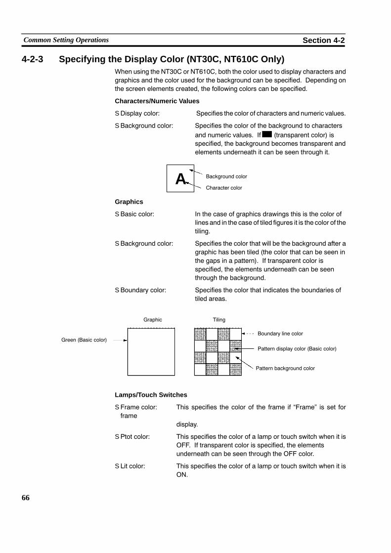
66
Common Setting Operations Section 4-2
4-2-3 Specifying the Display Color (NT30C, NT610C Only)When using the NT30C or NT610C, both the color used to display characters andgraphics and the color used for the background can be specified. Depending onthe screen elements created, the following colors can be specified.
Characters/Numeric Values
S Display color: Specifies the color of characters and numeric values.
S Background color: Specifies the color of the background to charactersand numeric values. If (transparent color) isspecified, the background becomes transparent andelements underneath it can be seen through it.
Background color
Character colorA
Graphics
S Basic color: In the case of graphics drawings this is the color oflines and in the case of tiled figures it is the color of thetiling.
S Background color: Specifies the color that will be the background after agraphic has been tiled (the color that can be seen inthe gaps in a pattern). If transparent color isspecified, the elements underneath can be seenthrough the background.
S Boundary color: Specifies the color that indicates the boundaries oftiled areas.
Pattern background color
Green (Basic color)
Graphic Tiling
Boundary line color
Pattern display color (Basic color)
Lamps/Touch Switches
S Frame color: This specifies the color of the frame if “Frame” is set forframe
display.
S Ptot color: This specifies the color of a lamp or touch switch when it isOFF. If transparent color is specified, the elementsunderneath can be seen through the OFF color.
S Lit color: This specifies the color of a lamp or touch switch when it isON.

67
Common Setting Operations Section 4-2
S Flashing color: This specifies the color of a lamp or touch switch when it isflashing. During flashing, the OFF color and ON color aredisplayed alternately.
Flashing color
When “OFF”
“OFF” color Frame color
When “ON”
“ON” colorFrame color
When flashing
“OFF” color
Reference: The appearance of lamps and touch switches during operation at the PT can bechecked in advance on the support tool screen by using the “Lamp/TSW DispMode” option in the environmental settings (tool settings for the “Edit” screen).
Graphs
S Frame color Specifies the color for the frame of a graph.
S Frame + range Specifies the color of the graph when the numericvalue is positive.
S Frame − range Specifies the color of the graph when the numericvalue is negative.
−100% 100%0%
−100% 100%0%−100%
100%
0%
−100%
100%
0%
Bar graph
When positive
Display colorfor positive value Frame color
When negative
Display colorfor negative value Frame color
Trend graph
“+” range in frame
Frame color “−” range in frame
Polygonal line graph
Frame color “−” range in frame
“+” range in frame

68
Common Setting Operations Section 4-2
4-2-4 Setting Numeral Memory TablesThis section describes how to set the initial values, and data area referenced in thePC, for numeral memory tables.
The number of numeral memory tables is determined by the “PT Type” setting, asfollows:
NT20S, NT20M: 128 tables
NT600S, NT600M: 256 tables
NT30, NT30C, NT612G, NT610C:1,000 tables (The number can be changed to 512 evenwhen using direct connection, in accordance with the sys-tem memory).
Reference: When using an NT30, NT30C, NT612G, or NT610C, numeral memory table num-bers 247 through 255 are used for the clock function and, therefore, setting opera-tions cannot be set for them.
[When not using direct connection]
[When using direct connection]
S No.: Numeral table number
S Init Val: Initial value

69
Common Setting Operations Section 4-2
S In: Execution/non-execution of numeral table initialization inaccordance with initial values set using the support toolwhen the PT is started up.
S #: Number of words used at the PC for reference by thenumeral table.
S Word: First word (lower word) in the data area at the PCreferenced by the numeral table.
The entry in the parentheses to the right is a comment inputwhen word setting was performed. It gives information suchas the contents of the word.
When direct connection is not used, only “Init Val” can be set.
Reference: If the host interface unit’s DIP switch is set for initialization of the data contents ofthe allocated words in the PC, the “Initial Value” setting will be invalidated.
<Setting method>
Procedure 1. Locate the bar cursor at the number of the numeral table to be set.
" [Shift] + [�] or [Shift] + [�] can be used to move the bar cursor to the previous ornext numeral table for which the “Init Val” setting is not “0”.
" Press the [Tab] key to display the memory table number input field.
" Press the [F1] (Ref) key to display the screen number that references a particu-lar numeral table.
" Press [F5] (Srch) to search for initial values or allocated words. See “Search-ing within a Memory Table” (p.78).
Reference: S Data can be copied into the next numeralmemory table by pressing [F2] (iCopy).Incrementing processing is performed in accordance with the setting made with[F3] (iCopySet). See “Copying to the Next Input Field (Increment Copy)” (p.77).
S Allocated bits of a numeralmemory table can be changed in a batchwith a desig-nated range by pressing [F4] (Btch Chng). See “Batch Changing Bits andWords” (p.79).
2. Press the key in the “Init Val” input field, input the initial value of the numeralmemory table, then press the key again.
Input numerical values can be deleted by pressing the [Home] key.
3. If using direct connection, to initialize the numeral memory table when it isstarted, move the bar cursor to the “In” input field and press the [SPACE] (Init)key.
4. If using direct connection, press the key in the “#” input field, input the num-ber of words (1 or 2), then press the key again.
5. Carry out word setting.
For details of the setting procedure, see “Setting Words and Bits” (p.75).

70
Common Setting Operations Section 4-2
4-2-5 Setting Character-String Memory TablesThis section describes how to set the initial values, and data area referenced in thePC, for character-string memory tables.
The number of character-stringmemory tables is determined by the “PT Type” set-ting, as follows:
NT20S, NT20M: 32 tables
NT600S, NT600M: 256 tables
NT30, NT30C, NT612G, NT610C:1,000 tables (The number can be changed to 256 evenwhen using direct connection, in accordance with the sys-tem memory).
Reference: Only “Initial Data” can be set for character-string memory table numbers 256through 999. It is not possible to reference PC data areas with these numbers.
[When not using direct connection]
[When using direct connection]
S No.: Character-string memory table number
S Initial Data: Initial value

71
Common Setting Operations Section 4-2
S In: Execution/non-execution of character-string tableinitialization in accordance with initial values set using thesupport tool when the PT is started up.
S #: Number of words used at the PC for reference by thecharacter-string memory table.
S Word: First word (lower word) in the data area at the PCreferenced by the character-string memory table.
The entry in the parentheses to the right is a comment inputwhen word setting was performed. It gives information suchas the contents of the word.
Reference: If the host interface unit’s DIP switch is set for initialization of the data contents ofthe allocated words in the PC, the “Initial Value” setting will be invalidated.
<Setting method>
Procedure 1. Locate the bar cursor at the number of the character-string memory table to beset.
" [Shift] + [�] or [Shift] + [�] can be used to move the bar cursor to the previous ornext character-string memory table for which the “Initial Data” setting is notblank.
" Press the [Tab] key to display the memory table number input field.
" Press the [F1] (Ref) key to display the screen number that references the char-acter-string memory table in question.
" Press [F5] (Srch) to search for initial values or allocated words. See “Search-ing within a Memory Table” (p.78).
Reference: S Data can be copied into the next character-string memory table by pressing [F2](iCopy). Incrementing processing is performed in accordance with the settingmade with [F3] (iCopySet). See “Copying to the Next Input Field (IncrementCopy)” (p.77).
S Allocated bits of a character-string memory table can be changed in a batch witha designated range by pressing [F4] (BtchChng). See “BatchChangingBits andWords” (p.79).
2. Press the key in the “Init Val” input field, input the initial value of the charac-ter-string memory table, then press the key again.
Input character-strings can be deleted by pressing the [Home] key.
3. If using direct connection, to initialize the character-string memory table whenit is started, move the bar cursor to the “In” input field and press the [SPACE](Init) key.
4. If using direct connection, press the key in the “#” input field, input the num-ber of words (1 to 20), then press the key again.
5. If using direct connection, carry out word setting.
For details of the setting procedure, see “Setting Words and Bits” (p.75).

72
Common Setting Operations Section 4-2
4-2-6 Bit Memory Table SettingThis setting sets screen switching functions, which switch the screen when a PCbit comes ON, and the alarm list/history function, which is actuated in accordancewith bit statuses (ON/OFF). The bit memory table allocations are also set in thissetting.
Bit memory tables can only be used with Ver.3 and later versions of the NT30,NT30C, NT610G, NT612G, and NT610C.
Reference: The allocated bits for the screen switching functions and alarm history function inthe bit memory tables are continually read by data communication while the PT isoperating. If too many settings are made, PT processing may be delayed.
S No.: Bit memory table number
S Hist: Execution/non-execution of bit status check (reading) foralarm history
S #: Presence/absence of screen switching function
S Table: Character-string memory table displayed in the alarm list/history
S Dsp Cl: Display color for the character-string memory table.For models other than the NT30C” and NT610C”, this coloris fixed as white.
S Image & Lib: Image library code displayed in the alarm history
S SwScreen: Displayed screen number if screen switching is executed
S Bit: Bit allocated in the bitmemory table. The parentheses to theright contain a comment indicating, for example, the functionof the bit).

73
Common Setting Operations Section 4-2
S Setting procedure
The bit memory table has the following two functions:
S Screen switching function
S Alarm list/history function
For details on these functions, refer to the user’s manual for the PT you are using.
<Setting screen switching functions>
Procedure 1. Locate the bar cursor at the “#” input field for the bit memory table with the re-quired number and press the SPACE (Hist/SWScreen) key.
S To register changes in bit statuses in the alarm history, also press the SPACEkey (Hist/SWScreen) in the “Hist” input field.
S [Shift] + and [Shift] + can be used to move the bar cursor to the previousand next positions in the bit memory table where there is a setting in the “Bit”column.
S Pressing the [Tab] key displays the memory table number input field.
S Pressing the [Home] (Delete) key clears the bit memory table setting at whichthe bar cursor is located (applies only if there is a setting in the “Bit” column).
S An allocated bit number search will be executed each time the [F5] (Srch) key ispressed. See “Searching Within a Memory Table” (p.78).
Reference: S Data can be copied into the next bit memory table by pressing [F2] (iCopy). See“Copying to the Next Input Field (Increment Copy)” (p.77).
S Allocated bits of a bit memory table can be changed in a batch with a designatedrange by pressing [F4] (Btch Chng). See “Batch Changing Bits and Words”(p.79).
2. Press the key in the “SwScreen” input field, input the screen number of thescreen whose display is to be switched, then press the key again.
When the screen switching function is used, the “Table”, “Dsp Cl”, and “Image& Lib” settings are invalid.
3. Carry out bit setting.
For details of the setting procedure, see “Setting Words and Bits” (p.75).

74
Common Setting Operations Section 4-2
<Setting the alarm list/history function>
Procedure 1. Locate the bar cursor at the number of the bit memory table to be set.
S To register changes in bit statuses in the alarm history, press the SPACE key(Hist/SWScreen) in the “Hist” input field.
S [Shift] + and [Shift] + can be used to move the bar cursor to the previousand next positions in the bit memory table where there is a setting in the “Bit”column.
S Pressing the [Tab] key displays the memory table number input field.
S Pressing the [Home] (Delete) key clears the bit memory table setting at whichthe bar cursor is located (applies only if there is a setting in the “Bit” column).
S An allocated bit number search will be executed each time the [F5] (Srch) key ispressed.. See “Searching Within a Memory Table” (p.78).
Reference: S Data can be copied into the next bit memory table by pressing [F2] (iCopy). See“Copying to the Next Input Field (Increment Copy)” (p.77).
S Allocated bits of a bit memory table can be changed in a batch with a designatedrange by pressing [F4] (Btch Chng). See “Batch Changing Bits and Words”(p.79).
2. Press the key in the “SwScreen” input field, input the character-stringmemory table number, then press the key again.
Pressing [F1] (Select) allows you to select the number from a displayed list.
3. If using an NT610C, specify the display color.
For details of the setting procedure, see “Specifying the Display Color” (p.66).
4. To display an image library entry, press the key in the “Image & Lib” inputfield, input the relevant code, then press the key again.
Pressing [F1] (Select) allows you to select the number from a displayed list.
5. To switch the display, input the screen number and press the key.
6. Carry out bit setting.
For details of the setting procedure, see “Setting Words and Bits” (p.75).
Reference: The allocated bits for the screen switching functions and alarm history function inthe bit memory tables are continually read by data communication while the PT isoperating. If too many settings are made, PT processing may be delayed.

75
Common Setting Operations Section 4-2
4-2-7 Setting Words and BitsThe words and bits referenced in the PC have to be set.
S Word/Bit:
In the case of numeral tables and character-string memory tables, specify thelower word number of the referenced words. In the case of lamps, touchswitches, and bit memory tables, set the bit number to be allocated.
The entries in the parentheses on the right hand side are comments. Commentscan be input to provide information such as the purpose of use of the word or bit(to input a comment, press the [F1] (Ref Inpt) key.
When specifying a DM are for a bit, append the bit number (00 to 15) at the end ofthe DM number.
Timers (TIM) and counters (CNT) cannot be set in bits or the words of character-strings.
Note When using a SYSMACBUS/2 interface unit, all the other bits in the same word asa bit used for touch switch input notification are turned OFF.
Direct Input Method
To make entries in the allocated bit/word input field directly by key input, press thekey while the cursor is in the input field, input the bit or word number, then press
the key again. If the number is input correctly it is confirmed. For details on theinput procedure, see “Character input” (p.54).
The following rules apply to bit and word input.
S Even if lower case letters are input, the characters will be upper case.
S If nothing is input, this will be interpreted as “no bit or word”.
S Symbols that indicate the type of bit or word, such as “AR”, “LR”, and “DM”, arecorrectly identified even if only the first character is input. However, in the caseof “CH” (I/O, internal relay area), correct identification is possible only whennothing is input at the head.
S Blanks (space) are ignored.
S The zeros that precede a bit or word number can be omitted.
S If the bit or word number exceeds the upper limit, a warning “pip” will sound andthe number will be changed to the maximum possible value.

76
Common Setting Operations Section 4-2
Short cut keys can also be used (see p.55).
Example
Specifying link relays (LR) for allocated bits:
Input After Input
[ ] [ ]
[L01] [L000001]
[LR0212] [L000212]
[12] [ 000012]
[Ir5601] [L005601]
[ LR914] [L000914]
[L999999] [L006300]
Reference Input Procedure
If you are not sure of the types of bit and channel that can be specified, it is possibleto display a list of the types that can be specified and select the type from amongthese. It is also possible to input a comment at this time.
<Setting method>
Procedure 1. Press the key in the allocated bit/word input field, then press [F1] (RefInpt).
The window shown below will be displayed.
2. Specify the type of bit or word by pressing the corresponding function key. If atype that cannot be input in the input field is selected, the selection is ignored.
3. Input the bit or word numberwith the numeral keys andpress the key. If theinput number exceeds the upper limit, a warning “pip” will sound and the num-ber will be changed to the maximum possible value.
If input is performed correctly, the cursor will shift to the comment input field.
4. If required, input a comment, then press the key. If no comment is re-quired, just press the key.
The window closes, and the bit/word number and comment are displayed inthe original input field.
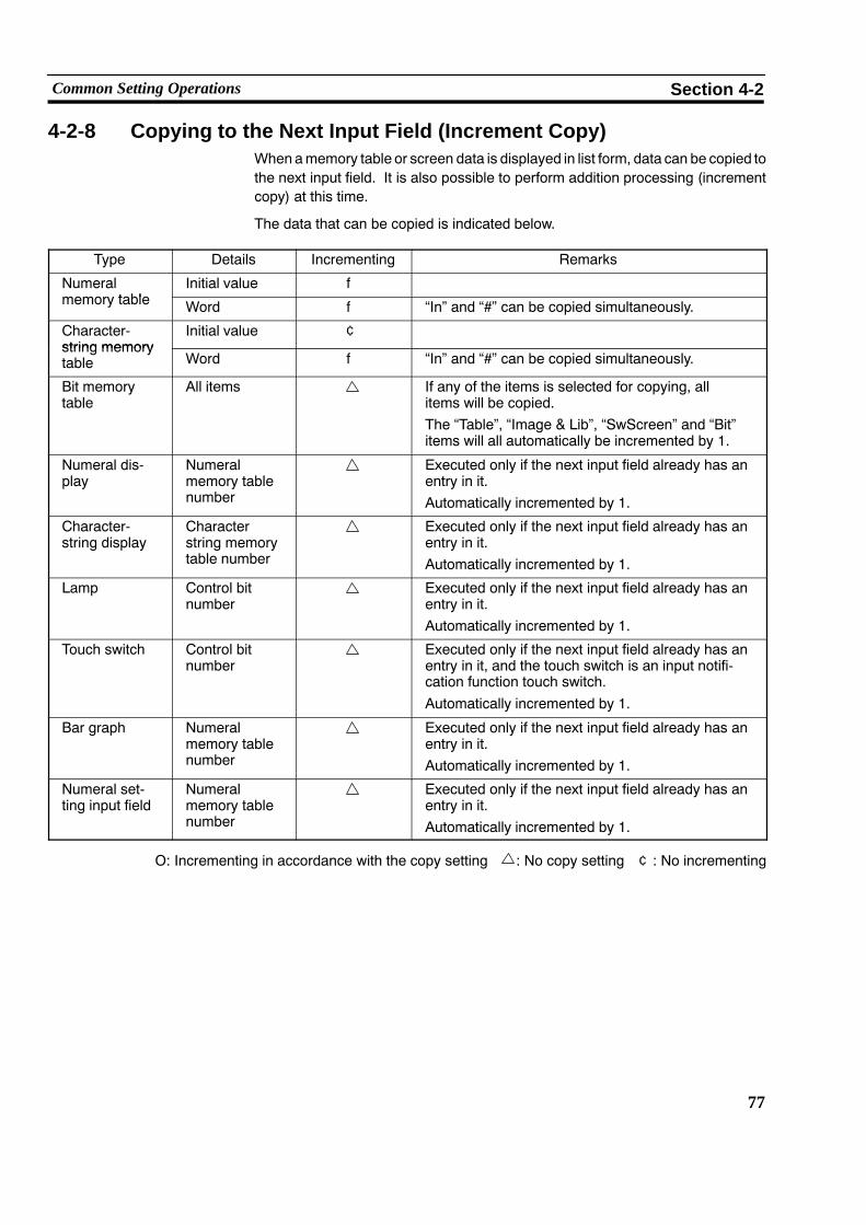
77
Common Setting Operations Section 4-2
4-2-8 Copying to the Next Input Field (Increment Copy)Whenamemory table or screen data is displayed in list form, data can be copied tothe next input field. It is also possible to perform addition processing (incrementcopy) at this time.
The data that can be copied is indicated below.
Type Details Incrementing Remarks
Numeralt bl
Initial value fmemory table Word f “In” and “#” can be copied simultaneously.
Character-string memory
Initial value ¢string memorytable Word f “In” and “#” can be copied simultaneously.
Bit memorytable
All items If any of the items is selected for copying, allitems will be copied.The “Table”, “Image & Lib”, “SwScreen” and “Bit”items will all automatically be incremented by 1.
Numeral dis-play
Numeralmemory tablenumber
Executed only if the next input field already has anentry in it.Automatically incremented by 1.
Character-string display
Characterstring memorytable number
Executed only if the next input field already has anentry in it.Automatically incremented by 1.
Lamp Control bitnumber
Executed only if the next input field already has anentry in it.Automatically incremented by 1.
Touch switch Control bitnumber
Executed only if the next input field already has anentry in it, and the touch switch is an input notifi-cation function touch switch.Automatically incremented by 1.
Bar graph Numeralmemory tablenumber
Executed only if the next input field already has anentry in it.Automatically incremented by 1.
Numeral set-ting input field
Numeralmemory tablenumber
Executed only if the next input field already has anentry in it.Automatically incremented by 1.
O: Incrementing in accordance with the copy setting : No copy setting ¢: No incrementing

78
Common Setting Operations Section 4-2
<Operation>
Procedure 1. To make a copy setting, press [F3] (iCopySet), input the value to be added oncopying, and the type of numerical value (decimal/hexadecimal), then pressthe key.
2. Locate the bar cursor at the item to be copied and press [F2] (iCopy).
The data will be copied to the next input field. Addition processing is carriedout in accordance with the nature of the copied data and the copy setting.
Repeated copy operations are possible by continuing to press the [F2] (iCopy)key.
4-2-9 Searching Within a Memory TableThis function is used to search for data in a numeral or character-string memorytable.
The data that can be searched for are tabled below.
Type Details
Numeral memory table Initial value
Word
Character-string memory table Initial value
Word
Bit memory table Bit
<Operation>
Procedure 1. Locate the bar cursor on the item to be searched for, press the [F5] (Srch) key,input the data to be searched for and the direction of the search, then press the
key.
The search will start. When the specified data is found, the bar cursor will belocated at its position.
2. To search for the next occurrence, press the key. To quit the search, pressthe [Esc] key.

79
Common Setting Operations Section 4-2
4-2-10 Batch Changing Bits and WordsThe bits andwords allocated tomemory tables and screen data can be changed inbatches with specified ranges.
The types of data for which batch change operations are applicable are indicatedbelow.
Type Details Remarks
Numeral memory table Word Executed using the numeral memory table setting window
Character-stringmemory table
Word Executed using the character-string memory table settingwindow
Bit memory table Bit Executed using the bit memory table setting window
Screen data Bit Executed for each screen after displaying the next itemwith [F10] (Next) on the “Screen Selection” screen.
Example
Changing a DM area to link relays (LR)
Before the change
Head word beforethe change
End word beforethe change
After the change
D001200
D001408
�
�
L003000
L003208
� Head word afterthe change
<Operation>
Procedure 1. Display the list of the data to be subjected to the batch change, press the [F4](Btch Chng) key, input the head and end words before the change, head wordafter the change, and presence/absence of a comment change, then press the
key.
S A window indicating the types of bits and words that can be input can be dis-played by pressing the [F1] (Ref Inpt) key.
S Bymarking screen data, bits andwords inmore thanone screen can be changedtogether.

80
Creating Fixed Displays Section 4-3
4-3 Creating Fixed DisplaysThis section describes how to create fixed characters and graphics in screen data.
The following characters and graphics can be created.
Characters (fixed display), marks (display)
Continuous lines, squares, polygons, circles/arcs, fans, tilings
When using an NT20S, NT20M, NT600S, or NT600M, only characters (fixed dis-play), continuous lines, and circles can be used (arcs cannot be used).
4-3-1 Inputting CharactersCharacters to be displayed have to be input. For details on the display of charac-ter-strings and numeric values, setting the display color (NT30C or NT610C), set-ting numeral tables, and setting words and bits, see 4-2 “Common Setting Opera-tions” (p.61).
Procedure 1. Select “FIX DISP” on the initial editing screen.
The fixed display menu will be displayed.
2. Select “STR IN”.
3. Input the characters to be displayed at the keyboard and press the key.
" Pressing the [F3] (Mark) key enables mark input.
" With the NT30, NT30C, NT612G, and NT610C, pressing the [F4] (Image) keyenables image input.
4. Set the Details and press the key.
5. If using an NT30C or NT610C, set the character color and background color.
6. Press the key with the cursor on “Exec”.
7. A box indicating the size of the character data is displayed.
Move this box to the required display position and press the key. The char-acters will be displayed.
8. Press the [Esc] key to quit character input.

81
Creating Fixed Displays Section 4-3
Deleting Displayed Characters
This is the procedure for deleting displayed characters. Deletion is executed incharacter-string units.
Procedure 1. Select “STR IN” from the fixed display menu.
2. Press the [F1] (Delete) key.
3. Locate the cross-hair cursor at a position inside the character-string to be de-leted and press the key. The selected character-string will be enclosed bya dotted line.
4. Check the message, then press to delete the character-string.
Modifying Displayed Characters
This is the procedure for modifying displayed characters, their character size, at-tributes, or position. Modification is executed in character-string units.
Procedure 1. Select “STR IN” from the fixed display menu.
It is also possible to proceed straight to step 4. by left clicking on the characterto be modified (see p.57).
2. Press the [F2] (Modify) key.
3. Locate the cross-hair cursor at a position inside the character-string to be mo-dified and press the key.
4. Select the required item in the window and modify the character-string.
S Modify String: Select to change characters.
S Set Display: Select to change the character font, scale, or displayattribute.
S Color: Select to change the character color or background color.(NT30C and NT610C only)
S Display Position: Select to move the character box in order to change thedisplay position.
5. Press the [Esc] key to quit modification.

82
Creating Fixed Displays Section 4-3
4-3-2 Inputting MarksCreated marks are input during screen editing. Marks can be handled in the sameway as characters and magnification scales can be specified for them.
However, smoothing is only possible for 16 x 16 dot marks when using an NT30,NT30C, NT612G, or NT610C.
Displaying Marks Select the mark that you want to display from the mark selection screen.
Marks can be displayed in the following two ways.
(1) Specification during character input
Press the [F3] (Mark) key after inputting characters or a label to display themark selection screen. Only 16 x 16 dot marks can be input.
(2) Specification using the fixed editing menu
Select “Mark” from the fixed display menu and specify the display position: themark selection screen will be displayed.
This operation cannot be used with the NT20S, NT20M, NT600S, orNT600M.
Select the mark to be displayed from this screen, specify the Details and char-acter color if using an NT30C or NT610C, then specify the display position.
32 x 32 and 64 x 64 dot marks can also be displayed at the same time.
The mark will be displayed in its actual form in the character input field. It willbe displayed on the editing screen with its bottom left extremity take as theorigin.
Deleting Marks Marks displayed on the screen can be deleted using the following method (markslocated inside character-strings can be deleted using the “STR IN” function).
Procedure 1. Select “FIX DSP” from the initial editing menu.
The fixed display menu will be displayed.
2. Select “MARK”.
3. Press the [F1] (Delete) key.
4. Locate the cursor at the mark to be deleted and press the key.
5. Check the message and then press the key.

83
Creating Fixed Displays Section 4-3
Modifying Marks Use the following procedure to modify marks displayed on the screen (marks lo-cated inside character-strings can be modified using the “STR IN” function).
Procedure 1. Select “FIX DSP” from the initial editing menu.
The fixed display menu will be displayed.
It is also possible to proceed straight to step 5. by left clicking on the mark to bemodified (see p.57).
2. Select “MARK”.
3. Press the [F2] (Modify) key.
4. Locate the cursor at the mark to be modified and press the key.
5. Select the required item and execute the modification.
S Modifying code: Select to modify a mark.
S Set display: Select to change the character font, scale, or displayattribute.
S Color: Select to change the character color or background color.(NT30C and NT610C only)
S Display position: Select to move the mark box in order to change the displayposition.
6. Press the [Esc] key to quit modification.

84
Creating Fixed Displays Section 4-3
4-3-3 Creating PolylinesThis is the procedure for drawing continuous lines (polygonal lines). It is possibleto connect a maximum of 255 individual line segments.
Procedure 1. Select “FIX DSP” from the initial editing menu.
The fixed display menu will be displayed.
2. Select “POLYLINE” from the fixed display menu.
3. Select the type of line.
The selectable options are solid line, broken line, 1-dot chain and 2-dot chain.
" It is not possible to use more than one line type in the same continuous line.
4. If using an NT30C or NT610C, specify the line color.
5. Press the key with the cursor on “Exec”
6. Draw the continuous line.
1) Press the key at the start point.
2) Locate the cursor at an intermediate point and press the key.
Set as many intermediate points as required.
3) At the end point, press the key while holding down the [Shift] key (ordouble click if using the mouse).
( )
( )
End point
Start point
Intermediatepoints (Shift+ )
" Pressing the [Esc] key before the end point has been set deletes the last drawnline segment.
" Pressing the [Esc] key while holding down the [Shift] key aborts the drawing.
7. Press the [Esc] key to quit continuous line drawing.
Deleting Polylines
Procedure 1. Select “POLYLINE” from the fixed display menu and then press the [F1] (De-lete) key.
A j mark will be displayed at the start point of the continuous line.
2. Locate the cursor at the j mark of the continuous line to be deleted and pressthe key.
3. Check the message and then press the key; the continuous line will be de-leted.
To abort deletion, press the [Esc] key.

85
Creating Fixed Displays Section 4-3
Modifying Polylines
Procedure 1. Select “POLYLINE” from the fixed display menu, then press the [F2] (Modify)key.
A j mark will be displayed at the start point of the continuous line.
It is also possible to proceed straight to step 3. by left clicking on the polyline tobe modified (see p.57).
2. Locate the cursor at the j mark of the continuous line to be modified and pressthe key.
3. Select the required item and execute the modification.
S Line Type: Select to change the line type.
S Color: If using an NT30C or NT610C, select to change the linecolor.
S Display position: The cursor moves to the end point of the continuous line.
Change the shape using the same operations as used fordrawing. Pressing the [Esc] key deletes the last straight lineand allows the creation of a new straight line.
After changing the shape, press the key while holdingdown the [Shift] key.
If using a mouse, double click.
4. Press the [Esc] key to quit modification.

86
Creating Fixed Displays Section 4-3
4-3-4 Creating SquaresThis is the procedure for drawing squares.
Procedure 1. Select “FIX DSP” from the initial editing menu.
The fixed display menu will be displayed.
2. Select “SQUARE” from the fixed display menu.
3. Select the display attribute with “Detail”.
The selectable options are “normal”, “inverted”, “flashing” and “spot”.
4. If using an NT30C or NT610C, specify the line color.
5. Press the key with the cursor on “Exec”
6. Draw the square.
1) Press the key at the start point.
2) Locate the cursor at the end point (diagonally opposite point) and press thekey.
End point
Start point ( )
( )
" Pressing the [Esc] key before the end point has been set aborts the drawing.
7. Press the [Esc] key to quit square drawing.
Deleting Squares
Procedure 1. Select “SQUARE” from the fixed display menu and then press the [F1] (De-lete) key.
A j mark will be displayed at the start point of the square.
2. Locate the cursor at the j mark of the square to be deleted and press thekey.
3. Check the message and then press the key; the square will be deleted.
To abort deletion, press the [Esc] key.

87
Creating Fixed Displays Section 4-3
Modifying Squares
Procedure 1. Select “SQUARE” from the fixed display menu, then press the [F2] (Modify)key.
A j mark will be displayed at the top left corner of the square.
It is also possible to proceed straight to step 3. by left clicking on the square tobe modified (see p.57).
2. Locate the cursor at the j mark of the square to be modified and press thekey.
3. Select the required item and execute the modification.
S Attribute: Select to change the display attribute.
S Color: If using an NT30C or NT610C, select to change the linecolor.
S Display position: Select to move the bottom right point of the square.
Pressing the [Esc] key makes it also possible to move thetop left point of the square.
Change the size and shape and then press the key.
4. Press the [Esc] key to quit modification.
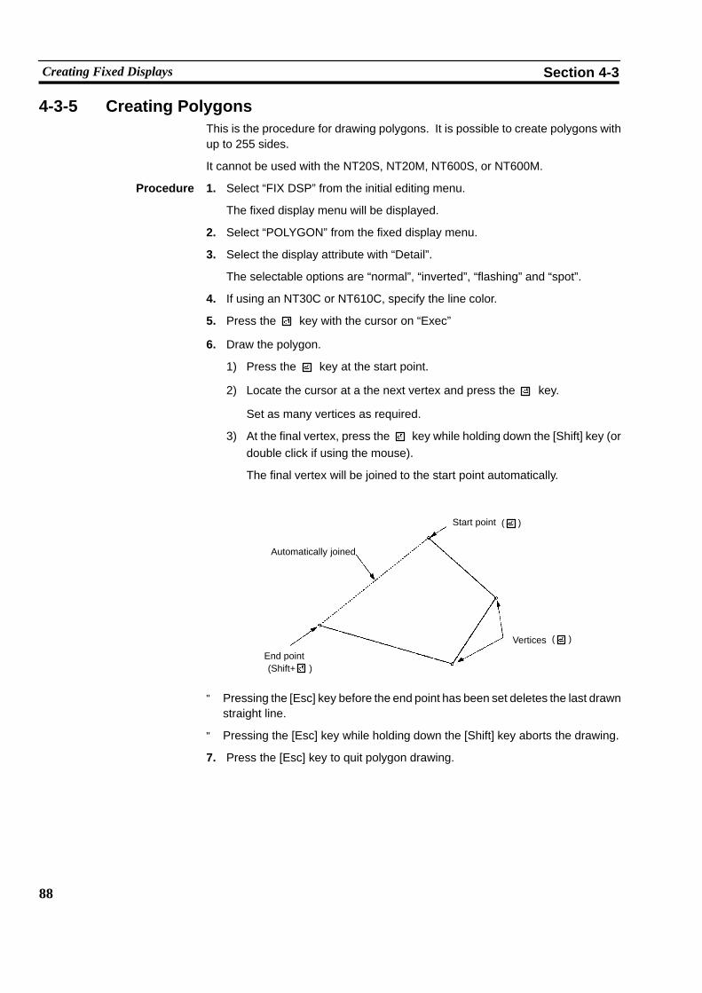
88
Creating Fixed Displays Section 4-3
4-3-5 Creating PolygonsThis is the procedure for drawing polygons. It is possible to create polygons withup to 255 sides.
It cannot be used with the NT20S, NT20M, NT600S, or NT600M.
Procedure 1. Select “FIX DSP” from the initial editing menu.
The fixed display menu will be displayed.
2. Select “POLYGON” from the fixed display menu.
3. Select the display attribute with “Detail”.
The selectable options are “normal”, “inverted”, “flashing” and “spot”.
4. If using an NT30C or NT610C, specify the line color.
5. Press the key with the cursor on “Exec”
6. Draw the polygon.
1) Press the key at the start point.
2) Locate the cursor at a the next vertex and press the key.
Set as many vertices as required.
3) At the final vertex, press the key while holding down the [Shift] key (ordouble click if using the mouse).
The final vertex will be joined to the start point automatically.
End point
Automatically joined
Start point
Vertices
(Shift+ )
( )
( )
" Pressing the [Esc] key before the end point has been set deletes the last drawnstraight line.
" Pressing the [Esc] key while holding down the [Shift] key aborts the drawing.
7. Press the [Esc] key to quit polygon drawing.

89
Creating Fixed Displays Section 4-3
Deleting Polygons
Procedure 1. Select “POLYGON” from the fixed display menu and then press the [F1] (De-lete) key.
A j mark will be displayed at the start point of the polygon.
2. Locate the cursor at the j mark of the polygon to be deleted and press thekey.
3. Check the message and then press the key; the polygon will be deleted.
To abort deletion, press the [Esc] key.
Modifying Polygons
Procedure 1. Select “POLYGON” from the fixed display menu, then press the [F2] (Modify)key.
A j mark will be displayed at the start point of the polygon.
It is also possible to proceed straight to step 3. by left clicking on the polygon tobe modified (see p.57).
2. Locate the cursor at the j mark of the polygon to be modified and press thekey.
3. Select the required item and execute the modification.
S Attribute: Select to change the display attribute.
S Color: If using an NT30C or NT610C, select to change the line color.
S Display position:
The cursor moves to the end point of the polygon.
Change the shape using the same operations as used for draw-ing. Pressing the [Esc] key deletes the last vertex and allowsthe creation of a new vertex.
After changing the shape, press the key while holding downthe [Shift] key.
S Attribute position:
Select to change the starting point for tiling when the “Normal”,“Flashing” or “Spot” attribute is set. Use this feature whengraphics are overlapped, making tiling difficult.
4. Press the [Esc] key to quit modification.

90
Creating Fixed Displays Section 4-3
4-3-6 Creating Circles/ArcsThis is the procedure for drawing circles and arcs.
Arcs cannot be created when using an NT20S, NT20M, NT600S, or NT600M.
Procedure 1. Select “FIX DSP” from the initial editing menu.
The fixed display menu will be displayed.
2. Select “CIRC/ARC” from the fixed display menu.
3. Select the display attribute with “Detail”
The selectable options are “normal”, “inverted”, “flashing”, and “spot”.
The selected attribute will be valid only for circles.
When using an NT20S, NT20M, NT600S, or NT600M, the attribute is fixed as“normal”.
4. If using an NT30C or NT610C, specify the line color.
5. Press the key with the cursor on “Exec”.
6. Draw the circular/arc.
1) Press the key at the center of the circle or arc.
2) Move the cursor to set the size of the circle or arc and press the key.
3) For a circle:
After setting the size, simply press the key once more.
For an arc:
Locate the cursor at the end point of the arc. Specify the direction in whichthe arc is to be drawn with the [Insert] key, then press the key.
Start point of the arc
Center
End point of the arc
( )
( )
( )
7. Press the [Esc] key to quit circle/arc drawing.

91
Creating Fixed Displays Section 4-3
Deleting Circles/Arcs
Procedure 1. Select “CIRC/ARC” from the fixed display menu and then press the [F1] (De-lete) key.
A j mark will be displayed at the start point of the circle/arc.
2. Locate the cursor at the j mark of the circle/arc to be deleted and press thekey.
3. Check the message and then press the key; the circle/arc will be deleted.
To abort deletion, press the [Esc] key.
Modifying Circles/Arcs
Procedure 1. Select “CIRC/ARC” from the fixed display menu, then press the [F2] (Modify)key.
A j mark will be displayed at the start point of the circle/arc.
It is also possible to proceed straight to step 3. by left clicking on the circle orarc to be modified (see p.57).
2. Locate the cursor at the j mark of the circle/arc to be modified and press thekey.
3. Select the required item and execute the modification.
S Attribute: Select to change the display attribute. This selection is onlyvalid if using an NT30, NT30C, NT612G, or NT610C.
S Color: If using an NT30C or NT610C, select to change the linecolor.
S Display position: Select to move the end point of an arc.
Pressing the [Esc] key makes it possible to change the startpoint and center point also.
After changing the shape, press the key.
4. Press the [Esc] key to quit modification.

92
Creating Fixed Displays Section 4-3
4-3-7 Creating FansThis is the procedure for drawing fans.
It cannot be used if using an NT20S, NT20M, NT600S, or NT600M.
Procedure 1. Select “FIX DSP” from the initial editing menu.
The fixed display menu will be displayed.
2. Select “FAN” from the fixed display menu.
3. Select the display attribute with “Detail”.
The selectable options are “normal”, “inverted”, “flashing”, and “spot”.
4. If using an NT30C or NT610C, specify the line color.
5. Press the key with the cursor on “Exec”
6. Draw the fan.
1) Press the key at the center of the fan.
2) Move the cursor to set the size and start point of the fan and press thekey.
3) Locate the cursor at the end point of the fan.
4) Specify the direct in which the fan is to be drawn by using the [Insert] key,then press the key.
Start point
End point ( )
( )
Center ( )
7. Press the [Esc] key to quit fan drawing.
Deleting Fans
Procedure 1. Select “FAN” from the fixed display menu and then press the [F1] (Delete) key.
A j mark will be displayed at the start point of the fan.
2. Locate the cursor at the j mark of the fan to be deleted and press the key.
3. Check the message and then press the key; the fan will be deleted.
To abort deletion, press the [Esc] key.

93
Creating Fixed Displays Section 4-3
Modifying Fans
Procedure 1. Select “FAN” from the fixed display menu, then press the [F2] (Modify) key.
A j mark will be displayed at the center of the fan.
" It is also possible to proceed straight to step 3. by left clicking on the fan to bemodified (see p.57).
2. Locate the cursor at the j mark of the fan to be modified and press the key.
3. Select the required item and execute the modification.
S Attribute: Select to change the display attribute.
S Color: If using an NT30C or NT610C, select to change the linecolor.
S Display position: Select to move the end point of the fan.
Pressing the [Esc] key makes it possible to change the startpoint and center point also.
After changing the shape, press the key.
4. Press the [Esc] key to quit modification.
4-3-8 TilingThis is the procedure for filling an area enclosed by lines, such as a square orcircle, with a specified tiling pattern.
It cannot be used if using an NT20S, NT20M, NT600S, or NT600M.
Procedure 1. Select “FIX DSP” from the initial editing menu.
The fixed display menu will be displayed.
2. Select “TILING” from the fixed display menu.
3. Select the tiling pattern with “Detail”.
4. If using an NT30C or NT610C, specify the base color, background color, andboundary color.
5. Press the key with the cursor on “Exec”
6. Locate the cursor inside the area to be tiled and press the key.
Any point inside an area that is enclosed by solid lines can be specified.
If using an NT30C or NT610C, make the specification inside the boundary col-or area.
7. A message asking for confirmation that the area is to be tiled will be displayed.

94
Creating Fixed Displays Section 4-3
Press the key to tile the area.
Press the [Esc] key to abort tiling.
8. Press the [Esc] key to quit tiling.
Take the display sequence into consideration when creating screen data (seep.53).
The tiling patterns on the support tool screen may differ a little from the tiling pat-terns on the PT screen.
Note If an area which is not closed is specified, the entire screen may be tiled. In addi-tion, when using an NT610C, if a graphic for which the boundary color is not closedis specified, the tiling may extend outside the specified area.
Example:
x : Point where tiling is specified(1): Boundary color(2): Boundary color
x (1)
x (2)
When tiling is specified at point (1), only the area inside the frame will be tiled, butwhen it is specified at (2), the area outside the frame will also be tiled from the partwhere the frames overlap.
Note Do not specify tiling inside graphics assigned the “flashing” attribute.

95
Creating Fixed Displays Section 4-3
Deleting Tiling
Procedure 1. Select “TILING” from the fixed display menu and then press the [F1] (Delete)key.
A j mark will be displayed at the point at which the tiling was specified.
2. Locate the cursor at the j mark of the tiling to be deleted and press thekey.
3. Check the message and then press the key; the tiling will be deleted.
To abort deletion, press the [Esc] key.
Modifying Tilings
Procedure 1. Select “TILING” from the fixed display menu, then press the [F2] (Modify) key.
A j mark will be displayed at the point where the tiling was specified.
" It is also possible to proceed straight to step 3. by left clicking on the tiling to bemodified (see p.57).
2. Locate the cursor at the j mark of the tiling to be modified and press thekey.
3. Select the required item and execute the modification.
S Detail: Select to change the tiling pattern.
S Color: If using an NT30C or NT610C, select to change the color.
S Display position: Select to change the tiling location.
4. Press the [Esc] key to quit modification.

96
Setting Numeral Displays Section 4-4
4-4 Setting Numeral DisplaysThis section describes how to display the contents of numeral tables on thescreen.
A maximum of 50 numeral displays can be set for display on one screen.
4-4-1 Setting Numeral DisplaysThis is the procedure for setting numeral displays. For details on the display ofcharacter-strings and numeric values, setting display colors (NT30C andNT610C), setting numeral tables, and setting words and bits, see 4-2 “CommonSetting Operations” (p.61).
Procedure 1. Select “NUM DISP” on the initial editing screen.
2. Select the field in which the numeral display is to be registered in the windowand press the key.
" To delete an entry that has already been set, locate the cursor at that numberand press the [F1] (Delete) key.
Reference: To “increment copy” an existing numeral display entry into the next input field (in-crementing the numeral memory table number), press the [F2] (iCopy) key withthe cursor located on that entry (see p.77).
3. Make the necessary settings.
4. Press the key with the cursor on “Exec”.
5. A box that indicates the size of the numeral display will be displayed.
Move this box to the required display position and press the key.
If required, more numeral displays can be set by repeating steps 2. through 5.
To quit numeral display, press the [Esc] key; the display will return to the menu.
Reference: If “Yes” is set for “Brkn Line Frame Disp” in the environmental settings (tool set-tings for the “Edit” screen), the display range for the numerals can be continuallymonitored on the screen.

97
Setting Numeral Displays Section 4-4
4-4-2 Modifying Numeral DisplaysThe contents and position of numeral displays created on the screen can bemodi-fied.
Procedure 1. Select “NUM DISP” on the initial editing screen.
" It is also possible to proceed straight to step 3. by left clicking on the numeraldisplay to be modified (see p.57).
2. In the window, select the entry corresponding to the numeral display to bemo-dified and press the key.
" It is also possible to make the selection by locating the mouse cursor on thenumeral display to be modified and clicking the left mouse button.
3. Select the required item in the window and execute the modification.
S Num Disp Setting: Select to change settings such as the referencedmemory table, the scale, and the attribute.
S Display Position: Select to change the display position.
4. Press the [Esc] key to quit modification.

98
Setting Character-string Displays Section 4-5
4-5 Setting Character-String DisplaysThis section describes how to display the contents of character-string memorytables on the screen.
The maximum number of character-string displays that can be set on one screenis 32 for the NT20S, 8 for the NT20M, and 50 for other models.
4-5-1 Setting Character-String DisplaysThis is the procedure for setting character-string displays. For details on the dis-play of character-strings and numeric values, setting display colors (NT30C andNT610C), setting numeral tables, and setting words and bits, see 4-2 “CommonSetting Operations” (p.61).
Procedure 1. Select “STR DISP” on the initial editing screen.
2. Select the field in which the character-string is to be registered in the windowand press the key.
" To delete an existing character-string from the field in which it is registered, lo-cate the cursor at that number and press the [F1] (Delete) key.
Reference: To “increment copy” an existing character-string numeral table entry into the nextinput field (incrementing the character-string memory table number), press the[F2] (iCopy) key with the cursor located on that entry (see p.77).
3. Make the necessary settings.
4. Press the key with the cursor on “Exec”.
5. A box that indicates the size of the character-string display will be displayed.
Move this box to the required display position and press the key.
If required, more character-string displays can be set by repeating steps 2.through 5.
To quit character-string display, press the [Esc] key; the display will return to themenu.
Reference: If “Yes” is set for “Brkn Line Frame Disp” in the environmental settings (tool set-tings for the “Edit” screen), the display range for the character-string can be contin-ually monitored on the screen.
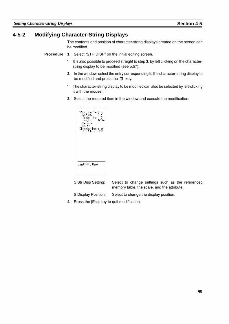
99
Setting Character-string Displays Section 4-5
4-5-2 Modifying Character-String DisplaysThe contents and position of character-string displays created on the screen canbe modified.
Procedure 1. Select “STR DISP” on the initial editing screen.
" It is also possible to proceed straight to step 3. by left clicking on the character-string display to be modified (see p.57).
2. In the window, select the entry corresponding to the character-string display tobe modified and press the key.
" The character-string display to bemodified can also be selected by left-clickingit with the mouse.
3. Select the required item in the window and execute the modification.
S Str Disp Setting: Select to change settings such as the referencedmemory table, the scale, and the attribute.
S Display Position: Select to change the display position.
4. Press the [Esc] key to quit modification.

100
Setting Lamps Section 4-6
4-6 Setting LampsThis section describes how to create lamp graphics whose display can be con-trolled from the PC.
The maximum number of lamps that can be set for display on one screen is 64 forthe NT20S and NT20M, 128 for the NT600S and NT600M, and 256 for the NT30,NT30C, NT612G, and NT610C.
Reference: When lamps are displayed in the same location as numeral table data or charac-ter-string memory table data, depending on the timing for lamp lighting andmemory table update timing, the lamp and numeral displays may overlap on thescreen. Refer to the operation manual for the PT you are using.
4-6-1 Setting LampsThis is the procedure for setting lamps. For details on the display of character-strings and numeric values, setting display colors (NT30C and NT610C), settingnumeral tables, and setting words and bits, see 4-2 “Common SettingOperations”(p.61).
By using the “Lamp/TSW Disp Mode” in the environmental settings (tool settingsfor the “Edit” screen), it is possible to check how lamps appear on the PT duringoperation by viewing the support tool screen.
Setting Normal Lamps
This is the procedure for setting “Normal lamps”, which come on, go off, or flash, inaccordance with the status of PC bits.
Procedure 1. Select “LAMP” on the initial editing screen.
2. Select the field in which the lamp is to be registered in the window and pressthe key.
S To delete an existing lamp from a field in which it is registered, locate the cursorat that number and press the [F1] (Delete) key.
Reference: To “increment copy” an existing lamp entry into the next input field (incrementingthe bit number), press the [F2] (iCopy) key with the cursor located in the “Bit” col-umn at that entry. Note that the next input field must also have an entry in it. (Seep.77).
3. When using an NT30, NT30C, NT612G, or NT610C with Ver.3 or a later ver-sion of the direct connection function, select “Normal” as the lamp type andpress the key.
When using an NT20S, NT20M, NT600S, or NT600M without direct connec-tion, the “Lamp Type Set” is not displayed.
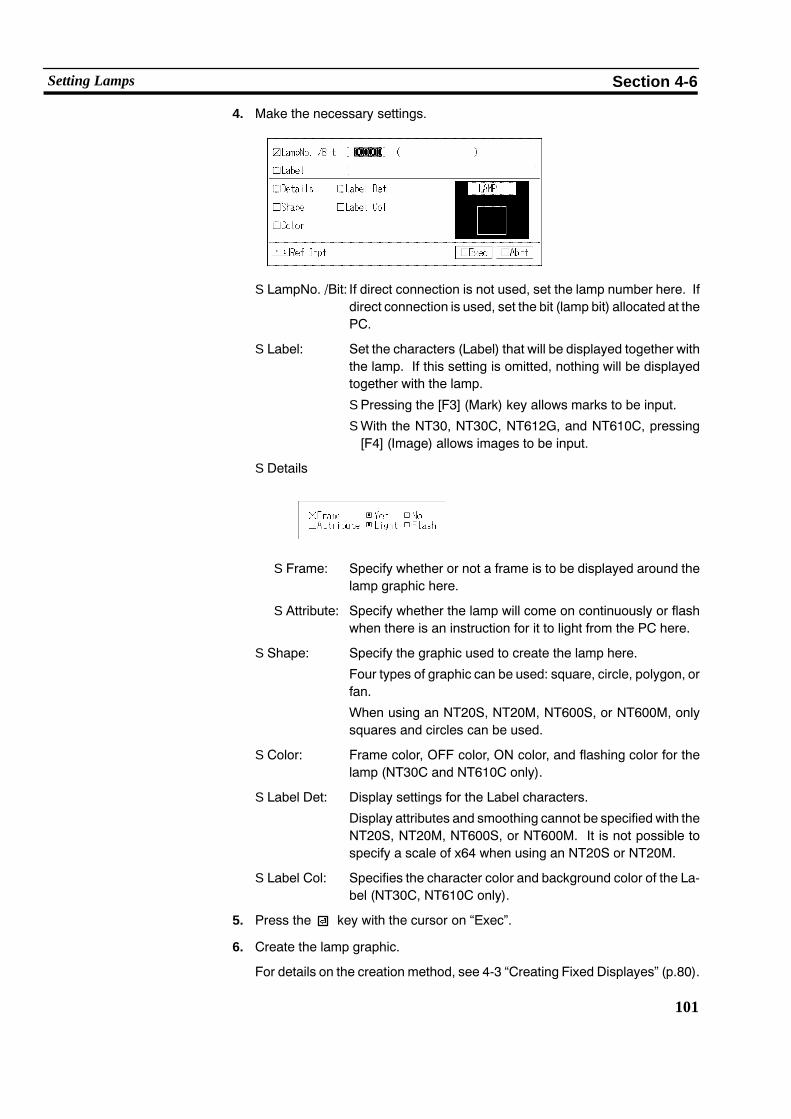
101
Setting Lamps Section 4-6
4. Make the necessary settings.
S LampNo. /Bit: If direct connection is not used, set the lamp number here. Ifdirect connection is used, set the bit (lamp bit) allocated at thePC.
S Label: Set the characters (Label) that will be displayed together withthe lamp. If this setting is omitted, nothing will be displayedtogether with the lamp.
S Pressing the [F3] (Mark) key allows marks to be input.
S With the NT30, NT30C, NT612G, and NT610C, pressing[F4] (Image) allows images to be input.
S Details
S Frame: Specify whether or not a frame is to be displayed around thelamp graphic here.
S Attribute: Specify whether the lamp will come on continuously or flashwhen there is an instruction for it to light from the PC here.
S Shape: Specify the graphic used to create the lamp here.
Four types of graphic can be used: square, circle, polygon, orfan.
When using an NT20S, NT20M, NT600S, or NT600M, onlysquares and circles can be used.
S Color: Frame color, OFF color, ON color, and flashing color for thelamp (NT30C and NT610C only).
S Label Det: Display settings for the Label characters.
Display attributes and smoothing cannot be specified with theNT20S, NT20M, NT600S, or NT600M. It is not possible tospecify a scale of x64 when using an NT20S or NT20M.
S Label Col: Specifies the character color and background color of the La-bel (NT30C, NT610C only).
5. Press the key with the cursor on “Exec”.
6. Create the lamp graphic.
For details on the creation method, see 4-3 “Creating Fixed Displayes” (p.80).

102
Setting Lamps Section 4-6
7. A box indicating the size of the label will be displayed in the center of the lampgraphic.
Move this box to the required display position and press the key.
If “No” is set for the “Label” setting in the “Lamp Setting” window, it will not bepossible to make this setting.
8. The specified label and lamp graphic will be displayed.
9. The screen on which registration fields for lamps can be selected will be dis-played.
To create another lamp, select a field.
To quit lamp creation, press the [Esc] key.
Setting Image/Library Lamps (NT30, NT30C, NT612G, NT610C, with Ver.2 Direct Connection Only)
This is the procedure for setting image/library lamps, which display different imagedata or library data according to the status of a PC bit.
When using an NT20S, NT20M, NT600S, or NT600M, when using an NT612G orNT610C and not using direct connection, or when using Ver.1 direct connection,this setting is not possible.
Procedure 1. Select “LAMP” on the initial editing screen.
2. Select the field for lamp registration in the window and press the key.
" To delete an existing lamp from the field in which it is registered, locate the cur-sor at that field and press the [F1] (Delete) key.
Reference: To “increment copy” an existing entry into the next input field (incrementing the bitnumber), press the [F2] (iCopy) key with the cursor located in the “Bit” column atthat entry (see p.77).
3. Select “Image & Lib” as the lamp type and press the key.

103
Setting Lamps Section 4-6
4. Make the necessary settings.
S Lamp Bit: Set the allocated bit in the PC.
S Ptot Code: Set the code for the image data or library data that is dis-played when the lamp is off (when the PC bit is OFF).
S Press the [F1] (Ref Inpt) key to enable selection of the codefrom a list display.
S If “0” is specified, nothing will be displayed when the lamp isoff.
S Light Code: Set the code for the image data or library data that is dis-played when the lamp is off (when the PC bit is ON).
S Press the [F1] (Ref Inpt) key to enable selection of the codefrom a list display.
S If “0” is specified, nothing will be displayed when the lamp ison.
5. Press the key with the cursor on “Exec”.
6. Specify the display position for the image data or library data that is displayedwhen the lamp is off, and press the key.
" If “0” (no display) is set for the code, it is not possible to specify a display posi-tion.
7. Specify the display position for the image data or library data that is displayedwhen the lamp is on, and press the key.
" If “0” (no display) is set for the code, it is not possible to specify a display posi-tion.
8. The screen on which registration fields for lamps can be selected will be dis-played.
To create another lamp, select a field.
To quit lamp creation, press the [Esc] key.

104
Setting Lamps Section 4-6
4-6-2 Modifying LampsIt is possible to modify the contents, shape, and position of created lamps.
Procedure 1. Select “LAMP” on the initial editing screen.
" It is also possible to proceed straight to step 3. by left clicking on the lamp to bemodified (see p.57).
2. Select the type of modification from the options in the window (“Lamp TypeSet” column) and press the key.
" It is also possible to select the lamp to be modified by left clicking on it (this ap-plies to displayed lamps only: depending on the setting for “Lamp/Touch SwDisp Mode” in the environmental settings, image/library lamps may not be vis-ible).
" For “Bit” (lamp bit) and “Label”, direct modification is possible by locating thecursor where the modification is to be made and pressing the key.
3. Select the type of modification from the options in the window and execute themodification.
For an “Image & library lamp”For a “Normal lamp”
S Set Display: Select to modify the item specified in the windowduring setting.
S Area Position: Select to modify the shape of the lamp graphic.
S Attrib Posiiton: Select to change the starting position for tilingwhenthe lamp is on or flashing. This item can only beused when a polygonal lamp is selected.
S Label Posiion: Select to modify the position at which the label isdisplayed.
S Ptot Position: Select to modify the position at which image/librarydata is displayed when the lamp is off.
S Light Positioin: Select to modify the position at which image/librarydata is displayed when the lamp is on.
4. Press the [Esc] key to quit modification.

105
Setting Touch Switches Section 4-7
4-7 Setting Touch SwitchesThis section describes how to create touch switch graphics that are displayed onthe PT screen and can be used as input switches.
The sensitive area (area that senses being touched) of a touch switch is not set inaccordance with the ordinary coordinates but with touch switch elements as theminimum units.
The number of touch switches that can be created for one screen and the size oftouch switch elements is determined by the “PT Type” setting, as follows:
NT Model Max. Number per Screen (whenusing/not using direct connection)
Size of TouchSwitch Elements(vert. x hori.)
NT20S, NT20M 64/72 21 x 21 dots
NT600S, NT600M 128/128 50 x 40 dots
NT612G 256/256 25 x 20 dots
NT30, NT30C,NT610C
256/256 20 x 20 dots
A grid that matches the size of the touch switch elements can be set by pressingthe [F1] (Tch Sw) key while the cursor is located on “Grid Display X Width” and“Grid Display Y Width” in the environmental settings.
Do not use the PT touch switch function for applicationswhere there is any danger to human life or possibility ofserious damage, or for an emergency stop switch function.
The same operations are used for both the NT610C and NT612G, with the excep-tion of color specification.
WARNING

106
Setting Touch Switches Section 4-7
4-7-1 Setting Touch SwitchesThis is the procedure for setting touch switches.
Touch switches can have the following functions, depending on the settings for“PT Type” and “Direct Access”:
FunctionNT20S, NT20M,NT600S, NT600M
NT612G,NT610C
NT30/C,NT620S/C RemarksFunction
None Ver.4 Ver.5 Ver.3 Ver.4Remarks
Input notification n n n f f n: ON/OFF only
Screen switching n1 n2 n2 f f n1: Standalone functionn2: No return key
Inputkeys
Characterkeys
x x x f f −y
Windowkeys
x x x n f n: Can only be used duringcharacter-string setting
Control keys n1 n2 n2 f f n1: Input notification keys withspecific numbers
n2: Numeric keys and systemkeys only
Copy setting x x x f f
Cursor motion x x x f f f: Window keys can also beset.
Print screen setting x x x f f Cannot be used with NT612G
S Input Notification: Notifying the PC that a touch switch has been pressed.
[NT20S, NT20M, NT600S, NT600M,direct connection not used]
[NT20S, NT20M, NT600S, NT600M, with Ver.4]
[NT612G, NT610C, direct connection not used]
[NT20S, NT600S, with Ver.5]
[NT30, NT30C, NT612G, NT610C, with Ver.3 or later]

107
Setting Touch Switches Section 4-7
S Noti Bit: Specify the PC bit that is notified that the touch switchhas been pressed here (only when direct connection isused).
S No.: Specify the number used to notify that a touch switchhas been pressed, or to control the touch switch on/off(flashing) status (used only when direct connection isnot used).
S Lamp Bit: Specify the bit in the PC that controls the on/off (flash-ing) status of the touch switch (used only when directconnection is used).
S Comment: Input a memo here, for example one that indicates thepurpose of use.
S Act Type: Specify the effect of pressing the touch switch here.
When using an NT20M or NT600M, or an NT20S or600S with Ver.5 direct connection, or using an NT612Gor NT610C and not using direct connection, or usingVer.1 direct connection, setting is not possible and thesetting is fixed as “Moment”.
Moment: The PC bit comes ON when the touchswitch is pressed and goes OFF when it isreleased.
Altnat: Each time the touch switch is pressed thestatus of the PC bit (ON/OFF) is changedto the opposite status.
Set: The PC bit is switched ON when the touchswitch is pressed.
Rset: The PC bit is switched OFF when thetouch switch is pressed.
Reference: Specification of notify bits and input of I/O comments is possible by using either theinput notification window or the touch switch setting screen.

108
Setting Touch Switches Section 4-7
S Screen Switching: Switching to a specified screenwhen the touch switch ispressed.
[NT20S, NT600S]
[NT20M, NT600M with Ver.4][NT30, NT30C, NT612G, NT610C,Ver.3 or later]
If using an NT20M or NT600M and not using direct connection, set screenswitching by using the “standalone” function (p.150).
S SwScreen No.: Specify the screen number of the screen to be dis-played here. When using an NT30, NT30C, NT612G,or NT610Cwith Ver.3 or a later version, if “0” is specifiedthe display will return to the screen that was displayedbefore the current one.
Reference: Screen switching numbers can be specified using either the screen switching win-dow or the touch switch setting screen.
S Character keys: Used as input keys when setting character-strings. Acharacter-string that is the same as the label on thetouch switch is input when the touch switch is pressed.These keys can only be used when using an NT30,NT30C, NT612G, or NT610C with Ver.3 or a later ver-sion of the direct connection function.

109
Setting Touch Switches Section 4-7
S Window keys: When one of these touch switches is pressed, the spe-cifiedwindow is opened or closed. These keys can onlybe used when using an NT30, NT30C, NT612G, orNT610C with Ver.3 or a later version of the direct con-nection function. (With Ver.3 they can only be used forcharacter-string settings.)
[NT612G, NT610C with Ver.3] [NT30, NT30C, NT612G, NT610C with Ver.4]
S Window Screen No.: Specify the screen number of the window to be calledhere.
S Type: Specify the operation when the touch switch is pressedhere. When using Ver.3, the setting is fixed as “open”.
S Open: The specified window is opened.
S Close: The open window is closed.
S Open/Close: Any open window is closed and the specified window isopened. If the specified window is already open, it isclosed.
S Control keys: Used as numeric keys and system keys in numeral set-ting.
[NT20S, NT20M, NT600S, NT600M, with Ver.4 or Ver.5]
[NT30, NT30C, NT612G, NT610C]
When using anNT20S, NT20M, NT600S, or NT600M, the control keys are spe-cified with touch switch numbers 231 to 255.
When using an NT20S, NT20M, NT600S, or NT600M with Ver.4 or Ver.5 of thedirect connection function, or anNT30, NT30C, NT612G, or NT610C, select thenumeric keys and system keys to be allocated to touch switches.
However, the last four items in the third row can only be selected when using anNT30, NT30C, NT612G, or NT610C, and the control keys in the bottom row canonly be selected when using an NT30, NT30C, NT612G, or NT610C with Ver.3or a later version of the direct connection function.

110
Setting Touch Switches Section 4-7
The touch switch control keys have the following functions:
Key Number Function
0 to 9, A to F 231 to 246 Used to input numerical values
CLR 247 Clears input numerical values and character-strings
248 Assigns the opposite sign to input numerical values
. 249 Used to input a decimal point
HOME 250 Used to move to the input field at the top left of the screen
� 251 Used to move to the next input field up (Y direction)
� 252 Used to move to the next input field down (Y direction)
� 253 Used to move to the input field to the left (X direction)
� 254 Used to move to the input field to the right (X direction)
255 system key (confirms character input without shifting to anotherinput field)
256 system key (stops the buzzer)
, 257, 258 and system keys (screen switching of continuous screens, shift-ing to input fields in the order in which they were registered with thesupport tool)
MENU 259 System keys + + (system menu display)
CA − Used to cancel input (Cancel)
BS − Deletes the numeral or character immediately preceding the inputcursor
DEL − Deletes the numeral or character at the input cursor location
A, " − Used to shift the input cursor
ENT − Confirms input of a character (after confirmation, the cursor shifts tothe next input field)
− Alarm list/history display page scrolling
Y, B − Alarm list/history line scrolling
S Copy Setting: When a touch switch is pressed, the contents of amemory table, or a code, are copied to the input field(cursor position) for a memory table or numeral/charac-ter-string setting. This function is only available whenusing anNT30, NT30C, NT612G, or NT610Cwith Ver.3or a later version of the direct connection function.
Copy From: Specify the type of copy source here.

111
Setting Touch Switches Section 4-7
No/Fixed: Specify thememory table number and numeric value (code) of thecopy source here. In the case of memory table specifications,pressing the [F1] (Lst Slct) key enables the selection to be madefrom a displayed list.
Copy To: Specify the type of copy destination here.
Crsr Posi: When copying between memory tables, specify the copy destina-tion memory table number here. Pressing the [F1] (Lst Slct) keyenables the selection to be made from a displayed list.
When copying to an input field (to the cursor position), the data iscopied into the specified input field when the touch switch ispressed. There are no particular specifications to be made.
S Cursor Motion: When a touch switch is pressed, the cursor moves tothe input field for a specified numeral/character-stringsetting. This function is only available when using anNT30, NT30C, NT612G, or NT610Cwith Ver.3 or a laterversion of the direct connection function (with Ver.4,window settings are also possible).
Select the input field to which the cursor will move. Input fields of the thumb-wheel type cannot be selected.

112
Setting Touch Switches Section 4-7
S Print Screen Setting: When a touch switch is pressed, printing of the dis-played screen is started or suspended. This function isonly available when using an NT30, NT30C, NT612G,or NT610Cwith Ver.2 or a later version of the direct con-nection function.
Reference: The type of printer used (EPSON Esc/P printer (24 pin)) and the printing methodwhen using an NT30C or NT610C (color, grayscale) are set using the memoryswitches on the PT body (see p.28).
The followingeight types of display area can be specified for touch switches. How-ever, note that the shapes that can be used depend on the settings made for “PTType” and “Direct Access”, as shown below:
Display AreaNT20S, NT20M,
NT600S,NT612G NT30, NT30C,
NT610CDisplay Area NT600S,NT600M Ver.3 or later Ver.3 or later
Normal f f f
Solid 1 f f f
Solid 2 x x f
None f f f
Square x f f
Circle x f f
Polygon x f f
Fan x f f
f: Can be used x : Cannot be used
In the case of squares, circles, polygons and fans, the sensitive area (the area thatsenses being touched) and display area (the area that lights, goes off, or flashes inaccordance with the status of the PC bit) can be specified separately.
Solid line: display areaBroken line: Sensitive area
Normal Solid(Solid 1)
Solid 2 None
Sensitive area = display area
Square Circle Polygon Fan
For details on the display of character-strings and numeric values, setting displaycolors (NT30C and NT610C), setting numeral tables, and setting words and bits,see 4-2 “Common Setting Operations” (p.61).

113
Setting Touch Switches Section 4-7
By using the “Lamp/TSW Disp Mode” function in the environmental settings (toolsettings for the “Edit” screen), it is possible to check how touch switches appear onthe PT during operation by viewing the support tool screen.
Procedure 1. Select “TOUCH SW” on the initial editing screen.
2. Select the field in which the touch switch is to be registered in the window andpress the key.
" To delete an existing touch switch from the field in which it is registered, locatethe cursor at that field and press the [F1] (Delete) key.
Reference: S To “increment copy” an existing touch switch into the next input field (increment-ing the bit number), press the [F2] (iCopy) key with the cursor located in the “Bit”column at that entry. Note that the next input field must also have an entry in it.(See p.77).
S Pressing the [Space] (open) key with the cursor located on the field of a createdwindow key will open thewindow that the key specifies. A windowopened in thisway can be closed by returning to the initial editing menu and pressing the [Tab](redisplay) key.
S The notify bit display can be changed to a lamp bit display either by pressing the[Insert] key or by clicking on the word “Bit” with the mouse. While the lamp bitdisplay is used, “Bit” is displayed.
3. Make the necessary settings.
S Function: On selecting the touch switch function and pressing , thewindow for that touch switch function will be displayed, allow-ing the appropriate settings to be made. However, specificwindows will not be displayed for the following:
S Input notification when not using direct connection
S Character keys (NT30, NT30C, NT612G, NT610C usedwith Ver.3 or later version only)
S Control keys when using an NT20S, NT20M, NT600S, orNT600M and not using direct connection
S Noti/Scrn No.:If not using direct connection, set the screen number of thescreen displayed when the touch switch is pressed. If usingdirect connection, set the PC bit used to notify the fact that theswitch has been pressed.

114
Setting Touch Switches Section 4-7
S No. /Lamp Bit:If not using direct connection, set the touch switch number. Ifusing direct connection, set the PC bit that controls the ON,OFF, or flashing state of the touch switch (lamp bit).
S Label: Set the characters (label) that will be displayed together withthe touch switch. If this setting is omitted, nothing will be dis-played together with the touch switch.
S Pressing the [F3] (Mark) key allows marks to be input.
S With the NT30, NT30C, NT612G, and NT610C, pressing[F4] (Image) allows images to be input.
S Details
S Inverse: Specifies whether the graphic will be inverted when there isinput on the PT screen.
[Normal, solid 1, square, circle, polygon, fan]
Other than NT30C and NT610C: Becomes inverted
NT30C, NT610C: Assumes the ON color
[Solid 2] (NT30, NT30C, NT610C only)
Inputinversion
S Attribute: Specify ON display or flashing display.
When using an NT20S, NT20M, NT600S, or NT600M, thesetting is fixed as “ON display” and cannot be specified.
S Shape: Specifies the type of touch switch display area.
S Color: Specifies the frame color, OFF color, ON color (inverted colorwhen ON) and flashing color (NT30C, NT610C only).
S Label Det:Set the label display settings.
Display attributes and smoothing cannot be specified with theNT20S, NT20M, NT600S, or NT600M. It is also not possible tospecify a scale of x64 when using an NT20S or NT20M.
S Label Col:Specifies the character color and background color of the “Label”(NT30C, NT610C only).
4. Press the key with the cursor on “Exec”.
5. If “square”, “circle”, “polygon”, or “fan” was specified for the shape of the dis-play area, create the graphic.
For details on how to create the graphic, see 4-3 “Creating Fixed Displays”(p.80).

115
Setting Touch Switches Section 4-7
6. Create the sensitive area for the touch switch.
Specify the start point and end point by using the cursor.
7. The specified label and touch switch graphic will be displayed.
8. The screen on which registration fields for touch switches can be selected willbe displayed.
To create another touch switch, select a field.
To quit touch switch creation, press the [Esc] key.
4-7-2 Modifying Touch SwitchesThe contents, shape, and position of a touch switch created on the screen can bemodified.
Procedure 1. Select “TOUCH SW” on the initial editing screen.
" It is also possible to proceed straight to step 3. by left clicking on the touchswitch to be modified (see p.57).
2. Select the touch switch to be modified in the window (“Func” field) and pressthe key.
" It is also possible to select the touch switch to be modified by left clicking on it.
" For “Bit” (notify bit) and “Label”, direct modification is possible by locating thecursor where the modification is to be made and pressing the key.
3. Select the type of modification from the options in the window and press thekey.

116
Setting Touch Switches Section 4-7
S Set Display: Select to change the function.
S Area Position: Select to change the frame of the display area.
S Attrib Position: Select to change the tiling start position when thetouch switch is lit or flashing.
This option is only displayed when a polygonaltouch switch is selected.
S Touch Sw Position: Select to change the sensitive area. The location ofthe modification (start point/end point) can bechanged by pressing the [Esc] key.
S Label Position: Select to change the display position of the label.
4. Press the [Esc] key to quit modification.

117
Creating Graphs Section 4-8
4-8 Creating GraphsThis section describes how to create graphs whose display corresponds to the nu-meric values in numeral memory tables. There are the following three types ofgraph.
When using an NT20S, NT20M, NT600S, NT600M, or NT612G, only bar graphscan be used.
S Bar graph: Numeral table contents are displayed in the form of abar graph.
43%
S Trend graph: Numeral table contents that change with time are dis-played in the form of broken lines.
Trend graphs can only be used when using an NT30,NT30C, NT612G or NT610C with Ver.3 or a later ver-sion of the direct connection function.
: Numeral table 1 84%: Numeral table 2 21%
Time
1000
0
S Broken line graph: The contents of several consecutive numeral tables aredisplayed in the form of a broken line. The display inter-vals can be changed without restriction.
Broken line graphs can only be used when using anNT30, NT30C, NT612G or NT610Cwith Ver.3 or a laterversion of the direct connection function. If using Ver.3or later, the display intervals can be changedwithout re-striction.
1000
00 53 421 53 4210
1000
0
Numeral table Numeral table
(After changing the interval)

118
Creating Graphs Section 4-8
4-8-1 Setting GraphsThese are the procedures for setting graphs. For details on the display of charac-ter-strings and numeric values, setting display colors (NT30C and NT610C), set-ting numeral tables, and setting words and bits, see 4-2 “Common Setting Opera-tions” (p.61).
Setting Bar Graphs A maximum of 50 bar graphs can be set for display on one screen.
When using an NT600S or NT600M, it is not possible to create bar graphs with awidth of greater than 256 dots.
Procedure 1. Select “GRAPH” from the initial editing screen.
2. If using an NT30, NT30C, NT612G or NT610C with Ver.3 or a later version ofthe direct connection function, select “BARGRAPH” from the graphmenu andpress the key.
If you are using an NT20S, NT20M, NT600S, or NT600M, the graph menu willnot be displayed.
3. Select the field in which the bar graph is to be registered in the window andpress the key.
" To delete an existing bar graph from the field in which it is registered, locate thecursor at that field and press the [F1] (Delete) key.
Reference: To “increment copy” an existing entry into the next input field (incrementing the nu-meralmemory table number), press the [F2] (iCopy) key with the cursor located onthat entry. Note that there must also be an entry in the next input field. (See p.77).
4. Make the necessary settings.
S Ref Way: Specify themethod used to reference thememory tableused for the display here.
" This item can only be set when using direct connec-tion. Only the “Direct” setting is valid. Do not select“Indrct”.

119
Creating Graphs Section 4-8
S Ref Table: Specify the number of the memory table to be refer-enced here.
Pressing the [F1] (Lst Slct) key enables selection from amemory table list.
S 100% Val
S 0% Val
S −100% Val: Specify the reference methods for 100%, 0%, and−100% values. If “Num Table” is specified, specify thenumeral table number.
If not using an NT30, NT30C, NT610G, or NT610C andVer.2 or a later version of the direct connection function,only the “Fix Num” setting for the 100% value is valid.
When “Num Table” is specified, pressing the [F1] (LstSlct) key enables the memory table to be selected froma displayed list.
S Display %: Specify whether or not a percentage value is displayedon the screen.
S Details
S Direction: Specify the orientation of the bar (up, down, right, left) here.
S Frame: Specify whether or not a graph frame is displayed here.
S Dsp Sign: Specify whether or not a minus sign is to be displayed in thecase of negative values here. If “Yes” is specified, the centerof the graph area is displayed at the origin to allow the displayof negative values.
S Color: Specify the display color of the bar graph when it showspositive values and the display color when it shows neg-ative values (NT30C, NT610C only).
S % Disp Det: Set the label display settings.
Display smoothing cannot be specified with the NT20S,NT20M, NT600S, or NT600M. It is also not possible tospecify a scale of x64 when using anNT20S or NT20M.
S % Col Set: Specifies the character color and background color ofthe “%” character (NT30C, NT610C only).

120
Creating Graphs Section 4-8
5. Press the key with the cursor on “Exec”.
6. Locate the cursor at the start point of the bar graph frame and press thekey. The bar graphwill be created as a rectangular graphic. Graphics orientedeither vertically or horizontally can be created.
7. A box that indicates the size of the percentage display will be displayed.
Move this box to the required display position and press the key.
If “No” is set for “Display %”, this box is not displayed.
8. The specified percentage display and bar graph will be displayed.
9. The screen on which registration fields for bar graphs can be selected will bedisplayed.
To create another bar graph, select a field.
To quit bar graph creation, press the [Esc] key.
Setting Trend Graphs (NT30, NT30C, NT612G, or NT610C with Ver.3 or later only)
One trend graph frame can be created per screen, and up to 50 broken lines canbe set within this frame.
Procedure 1. Select “GRAPH” from the initial editing screen.
The graph menu will be displayed.
2. Select “TREND GRAPH” from the graph menu.
" If there is already a trend graph, the screen for selecting the field for registrationis displayed. Selecting an empty field allows you to proceed to step 7.
3. Locate the cursor at the start point for the trend graph frame and press thekey.
Trend graphs are created as rectangular graphics. They can be oriented ei-ther vertically or horizontally.
4. Locate the cursor at the end point of the trend graph frame and press thekey.

121
Creating Graphs Section 4-8
5. Set the basic settings for the trend graph as required.
S Type: Specify the type of trend graph.
Normal: The graph remains in a fixed position andsuccessive points in the graph are drawnin the “Mv Direction”.
Pen Reco: The latest point is always drawn at a fixedposition and the entire graph moves in the“Mv Direction”.
S Dw Width: Specify the direction in which the broken line moveswith time here.
S Sampling Cycl: Specify the cycle in which the graph is rewritten in 0.1second units (range: 1 to 65535 = 0.1 to 6553.5 se-conds)
S Mv Direct: Specify the direction in which the broken lines movewith time.
S Details
S Frame: Specify whether or not a graph frame is displayed.
If “No” is specified here only the broken lines within thegraph are displayed.
S Dsp Sing: Specify whether or not a minus sign is to be displayedin the case of negative values here. If “Yes” is speci-fied, the center of the graph area is displayed at the ori-gin to allow the display of negative values.
S Color: Specify the graph’s frame color, the color of the positivearea inside the frame, and the color of the negativearea inside the frame (NT30C, NT610C only).
6. Press the key with the cursor on “Exec”.

122
Creating Graphs Section 4-8
7. Set the required display settings for the trend graph.
These settings have to be made for each broken line.
S Ref Way: Specify the method used to reference the memorytable used for the display here.
Only the “Direct” setting is valid. Do not specify the“Indrct” setting.
S Ref Table: Specify the number of the memory table to be refer-enced here.
Pressing the [F1] (Lst Slct) key enables selection froma memory table list.
S 100% Val:
S 0% Val:
S −100% Val: Specify the reference methods for 100%, 0%, and−100% values. If “Num Table” is specified, specify thenumeral table number.
Pressing the [F1] (Lst Slct) key while “Num Table” isspecified allows the memory table to be selected froma displayed list.
S Display %: Specify whether or not a percentage value is displayedon the screen.
S Line: Specify the line type for the broken lines.(Sold Lin, Brkn Lin, 1 Dot Chn, 2Dot Chn)
S Line Col: Specify the display color of the broken lines (NT30C,NT610C only).
S % Disp Det: Specify the label display settings.
Display attributes and smoothing cannot be specifiedwith the NT20S, NT20M, NT600S, or NT600M. It isalso not possible to specify a scale of x64 when usingan NT20S or NT20M.
S % Col Set: Specifies the character color and background color ofthe “%” character (NT30C, NT610C only).

123
Creating Graphs Section 4-8
8. Press the key with the cursor on “Exec”.
9. A box that indicates the size of the percentage display will be displayed.
Move this box to the required display position and press the key.
If “No” is set for “Display %”, this box is not displayed.
10. The specified percentage display and trend graph will be displayed.
11. The screen onwhich registration fields for trend graphs can be selected will bedisplayed.
To create another trend graph, select a field.
Further broken lines can be added by repeating the operation from step 7.
To quit trend graph creation, press the [Esc] key.
Reference: S If a broken line extends beyond the frame, only the part contained by the framewill be displayed, as shown below.
S Each time the [Tab] key is pressed, the graph display changes.
Setting Broken Line Graphs (NT30, NT30C, NT612G, NT610C with Ver.3 or Later)
No more than one frame for a broken line graph can be created per screen; up to256 broken lines can be set within this frame. Each broken line can display thedata in up to 512 numeral tables. Broken line graph frames can be set for screen(maximum of eight) in an overlapping screen but in this case that the total numberof broken lines for the overlapping screen as a whole cannot exceed 256.
Procedure 1. Select “GRAPH” from the initial editing screen.
The graph menu will be displayed.
2. Select “BRK-LIN GRAPH” from the graph menu.
" If there is already a broken line graph (or graphs), the screen for selecting thefield in which the broken line graph is to be registered is displayed. Select anempty field to proceed to step 7.
3. Locate the cursor at the start point for the broken line graph frame and pressthe key.
Broken line graphs are created as rectangular graphics. They can be orientedeither vertically or horizontally.
4. Locate the cursor at the end point of the broken line graph frame and press thekey.

124
Creating Graphs Section 4-8
5. Set the basic settings for the broken line graph as required.
S Mv Direct: Specify the direction in which the broken line is to bedrawn in accordance with the ascending order ofmemory table numbers here.
S Detail Info
S Frame: Specify whether or not a graph frame is displayed.
If “No” is specified here only the broken lines within thegraph are displayed.
S Disp Sign: Specify whether or not a minus sign is to be displayedin the case of negative values here. If “Yes” is speci-fied, the center of the graph area is displayed at the ori-gin to allow the display of negative values.
S Color: Specify the graph’s frame color, the color of the positivearea inside the frame, and the color of the negativearea inside the frame (NT30C, NT610C only).
6. Press the key with the cursor on “Exec”.
7. Set the required display settings for the broken line graph.
These settings have to be made for each broken line.

125
Creating Graphs Section 4-8
S Ref Table: Specify the memory table number from which refer-ence is to be started here.
Pressing the [F1] (Lst Slct) key allows the memorytable to be selected from a list.
S Points: Specify the number of vertices in the broken line.
The contents of a number of numeral tables equivalentto this number and starting with the “reference starttable” will be displayed in the form of a broken line.
S 100% Val:
S 0% Val:
S −100% Val: Specify the reference methods for 100%, 0%, and−100% values. If “Num Table” is specified, specify thenumeral table number.
Pressing the [F1] (Lst Slct) key while “Num Table” isspecified allows the memory table to be selected froma displayed list.
S Line: Specify the line type for the broken lines.
(Solid line, broken line, 1-dot chain, 2-dot chain)
S Color: Specify the display color for the broken lines (NT30Cand NT610C only).
8. Press the key with the cursor on “Exec”.
9. The screen on which registration fields for broken line graphs can be selectedwill be displayed.
To create another broken line graph, select a field.
Further broken lines can be added by repeating the operation from step 7.
To quit broken line graph creation, press the [Esc] key.
Reference: S If a broken line extends beyond the frame, only the part contained by the framewill be displayed, as shown below.
S Each time the [Tab] key is pressed, the graph display changes.

126
Creating Graphs Section 4-8
4-8-2 Modifying GraphsThe contents and position of a graph created on the screen can be modified.
Reference: When using an NT30, NT30C, NT612G, or NT610C and Ver.3 or a later version ofthe direct connection function, the interval between the vertices in a broken linegraph can be changed as required during modification.
Procedure 1. Select “GRAPH” on the initial editing screen.
The graph menu will be displayed.
" It is also possible to proceed straight to step 4. by left clicking on the graph to bemodified (see p.57).
2. Select the type of graph to bemodified from the graphmenu and press thekey.
3. Select the graph to be modified in the window and press the key.
" To delete a graph that has already been set, locate the cursor at the field for thatgraph and press the [F1] (Delete) key.
Batch deletion of trend graphs and broken line graphs in frame units is possibleby pressing the [F2] (All delete) key. Pressing the [F10] (Basic) key allowsmodification of the basic settings.
4. Select the required item and execute the modification.
For details on the meanings of each of the items, refer to the sections describ-ing the creation of each of the graph types.
Broken linegraph
Trend graphbasic settings
Trend graph Broken line graphbasic settings
Bar graph

127
Creating Graphs Section 4-8
S “Brkn-Line Grph Intv” setting
Used to change the interval between vertices in a broken line graph.
Use the space key to assign and delete marks. Vertices will be displayed at thelocations where marks have been assigned. Always assign a number of marksequal to the number of vertices (if the numbers of vertices and marks do not thesame, interval setting cannot be completed).
Number of vertices
Edge of graph
Number of marks
Use the [� ]/[� ] keys to move to the location where a mark is to be assigned andthe [Page Up]/[Page Down] keys to shift the display range to the left or right.
Press the key to quit interval setting.
5. Press the [Esc] key to quit modification.

128
Creating Input Settings Section 4-9
4-9 Creating Input SettingsThis section describes how to create the “numeral setting” and “character-stringsetting” input fields required to input numeric values and character-strings from atouch panel or extended I/O unit.
What is a “Numeral Setting”?
Once a numeral setting input field has been created, it is possible to input numericvalues from touch switches or extended I/O units.
The touch switches used to input numeric values (numeric keys) can be arrangedwithout restriction on the screen. See “Creating Numeric Keys” (p.136).
There are the following two types of input for numeral settings.
The thumbwheel type can only be usedwith the following combinationsof PTmod-el and direct connection version.
S NT20S or NT600S with Ver.5
S NT30 or NT30C with Ver.4
S NT612G or 610C with Ver.3
Reference: Whennot using direct connection, the touch switch or extended I/O unit is selectedin accordance with the screen bit input attribute.
When not using direct connection, the correspondence between extended I/O unitinput terminals and numeric keys is fixed. Refer to the operationmanual for the PTyou are using.
S Numeric keys: Used to input numeric values into input fields as if using anelectronic calculator.
S Thumbwheel: There is a plus/minus touch switch for each digit of the numericvalue and the value is input in one digit units (input from an ex-tended I/O unit is not possible). This function is only availablewhen using an NT20S or NT600S with Ver.5 of the direct con-nection function, or an NT30, NT30C, NT612G, or NT610Cwith Ver.3 of the direct connection function.

129
Creating Input Settings Section 4-9
The switches come in three sizes, as shown below.
With thumbwheel setting, if “Yes” is set for “Disp Sign”, the maxi-mum number of digits in the numeric value is reduced to 7.
When using an NT20S, only “small” and “medium” can be used,and when using an NT600S, only “medium” can be used.
Small
Medium
Large
What is a “Character-string Setting”?
Once a character-string setting has been created, the label that appears on atouch switch can be input as a character-string with one press of the switch.
In addition, if several window screens (keyboard screens) −which each comprisea group of related touch switches − are created, the windows required for specificpurposes can be displayed whenever necessary, allowing various types of input.
Windows can be created in screen numbers 1900 through 1979 and can be dis-played by pressing touch switches that have been set as “window keys”.
Character-string settings and window displays can only be used when using anNT30, NT30C, NT612G, or NT610C with Ver.3 or a later version of the direct con-nection function.
Reference: Character-string setting and keyboard display is only possible when using directconnection.
Character-string setting screen
Window screen
TYPE
numerals
letters
numerals
letters
TYPE
Window opening touch switches
Window openingtouch switch pressed

130
Creating Input Settings Section 4-9
Reference: Temporary input fields
Only one numeral or character string setting input field can be registered for a win-dow (screen number in the range 1900 through 1979). This input field can be used− in combination with a number of numeral and character-string input fields onbase screens − for provisional input before any data is input into the actual inputfield on the base screen. This kind of numeral or character-string input field in awindow is called a “temporary input field”.
Its advantage is that entries can be input into the temporary input field while check-ing the current setting on the base screen.
However, if the temporary input field in the window and the input field on the basescreen are not of the same type, the temporary input field will not be displayed.Note also that temporary input fields cannot be used for thumbwheel type inputfields. If it is not possible to use a temporary input field, the data has to be inputdirectly onto the base screen.
Numeral setting input Temporary input field (displays data being input)
Currentsetting Window
The temporary input field will also be unusableand not displayed if it has fewer digits than theactual input field on the base screen (number ofinteger digits + number of decimal fraction digits+ digit for decimal point + digit for sign).
1 2 3 4 5 6
−4 1.8
0 0 2 .710
7 8 9 �4 5 6 �1 2 3 �0 . ENT
555 .440
The temporary input field displays the contents of the current input field at thatpoint in time. The display of the temporary input field is governed by the followingattributes:
S Attributes determined by the settings for the temporary input field:
Character font, scale, display attribute, smoothing, character color, backgroundcolor
S Attributes determined by the settings for the actual input field on the basescreen:
Numbers of integer and decimal fraction digits, upper limit value, lower limit val-ue, decimal/hexadecimal, zero suppress, sign display.

131
Creating Input Settings Section 4-9
4-9-1 Creating Numeral Setting Input FieldsThis is the procedure for creating input fields for numeral settings. For details onthe display of numeric values, setting display colors (NT30C andNT610C), settingnumeral tables, and setting words and bits, see 4-2 “Common SettingOperations”(p.61).
Procedure 1. Select “IN SET” from the initial editing screen.
The input setting menu will be displayed.
2. Select “DATA IN” from the input setting menu.
3. Select the field in which the numeral setting input field is to be registered andpress the key.
" To delete an existing numeral setting from the field in which it is registered, lo-cate the cursor at that field and press the [F1] (Delete) key.
Reference: When using direct connection, to “increment copy” an existing entry into the nextinput field (incrementing the memory table number), press the [F2] (iCopy) keywith the cursor located on that entry. Note that there must also be an entry in thenext input field. (See p.77).
4. If the input type can be specified, specify either “Number Input” or “Thumb-wheel”, specify “Mv Crsr Sw” if necessary, then press the key.
" If the thumbwheel type cannot be used, the input type selection windowwill notbe displayed.
" If “Mv Crsr Sw” is set for “Yes”, touch switches for which the “cursor motion”function has been set will be automatically created and displayed overlying theinput field (this function is not availablewhen using the thumbwheel input type).

132
Creating Input Settings Section 4-9
5. Set the necessary settings for the numeral setting input field.
[Thumbwheel]
[Numeric keys]
(NT20M, NT600M, without direct connection)
[Numeric keys]
(NT20S, NT600S, NT612G, NT610C, withoutdirect connection)
[Numeric keys]
(Ver.1 to Ver.5)
The settings that are specific to numeral setting are listed below.
S Sending: Specify the number of digits in the value notified to the host.
S Dig Input: Specify the number of digits that can be input.
S Max, Min: Specify the upper and lower limits for the numeric value.
S Num Disp: Specify whether or not the input is displayed.
S Crsr Frm: Specify whether or not a cursor frame, which indicates thecurrently selected input field, is to be displayed, here.
S Slct Frm: Specify the display method for the cursor frame here.
S Size: Specify the size for thumbwheel type touch switches here.
S End plate: Specify whether or not end plates are to be displayed at theleft and right of thumbwheel type switch displays.

133
Creating Input Settings Section 4-9
6. Press the key with the cursor on “Exec”.
7. A box indicating the size of the input field will be displayed.
Locate this box at the required display position and press the key.
8. The specified input field for display setting, numeric keys, or system keys, willbe displayed.
" If the keypad attribute for the screen is “User”, numeric keys and system keysare not displayed. If the numeral setting attribute is changed from “Syst” to“User” after completing numeral setting, the numeric keys and system keys willbe lost.
System keys
Numeric keys
Input field
Reference: The two numeral setting attributes are used in the following cases:
“Syst”: Used to eliminate the need to carry out screen creation by usingthe PT default input keys.
“User”: Used when creating customized input keys.
9. It is now possible to select another registration field and create another numer-al setting input field.
Press the [Esc] key to quit numeral setting.

134
Creating Input Settings Section 4-9
4-9-2 Creating Character-String Setting Input Fields(NT30, NT30C, NT612G, NT610C with Ver.3 or Later Only)
This is the procedure for creating input fields for numeral settings. For details onthe display of character-strings, setting display colors (NT30C or NT610C), settingnumeral tables, and setting words and bits, see 4-2 “Common SettingOperations”(p.61).
Procedure 1. Select “IN SET” from the initial editing screen.
The input setting menu will be displayed.
2. Select “DATA IN” from the input setting menu.
3. Select the field in which the character-string setting input field is to be regis-tered and press the key.
" To delete an existing character-string setting input field from the field in which itis registered, locate the cursor at that field and press the [F1] (Delete) key.
Reference: To “increment copy” an existing entry into the next input field (incrementing thememory table number), press the [F2] (iCopy) key with the cursor located on thatentry. Note that there must also be an entry in the next input field. (See p.77).
4. Specify “Str In”, specify “Mv Crsr Sw” if necessary, then press the key.
" If “Mv Crsr Sw” is set for “Yes”, touch switches for which “cursor motion” hasbeen set will be automatically created and displayed overlying the input field.
5. Set the necessary settings for the character-string input field.
The settings that are specific to character-string setting are listed below.
S Details
S Crsr Frm: Specify whether or not a cursor frame, which indicatesthe currently selected input field, is to be displayed,here.
S Slct Frm: Specify the display method for the cursor frame here.
6. Press the key with the cursor on “Exec”.
7. A box indicating the size of the input field will be displayed.
Locate this box at the required display position and press the key.
8. The input field for the specified display setting will be displayed.
9. It is now possible to select another registration field and create another char-acter-string setting input field.
Press the [Esc] key to quit character-string setting.

135
Creating Input Settings Section 4-9
4-9-3 Setting Window Displays(NT30, NT30C, NT612G, NT610C with Ver.3 or Later Only)
This is the procedure for setting windows to be displayedwhen a switch is made toa character-string setting screen.
It is also possible to display a created window and check the display position etc.during screen creation. It is possible to arrange elements on the screen so thatthey do not overlap with the displayed window.
Procedure 1. Select “IN SET” from the initial editing screen.
The input setting menu will be displayed.
2. Select “KEYBD/WINDOW DISP” from the input setting menu.
3. Specify the screen number of the window to be displayed when the screen isdisplayed and press the key.
The specified window will be displayed.
" If “0” is specified, the window display disappears, and when the screen is dis-played during operation, it is displayed without the window.
Reference: To check the display status when another window is displayed, repeat steps 1through 3.

136
Creating Input Settings Section 4-9
4-9-4 Creating Numeric KeysNumeric keys are touch switches for inputting numeric values. If the keypad attrib-ute for the screen is set as “User”, the keys can bepositionedwherever required onthe screen.
The arrangement of the numeric keys displayed on the screen can be changed byusing the “TOUCH SW” and “EDIT” functions on the “Edit” screen.
Procedure 1. On the “Screen Selection” screen, locate the cursor at the screen number forwhich the numeric keys are to be created and press the [F4] (Attrib) key.
2. Set “User” for “Keypad”.
" “F” will be displayed in the “Status” column of the screen for which attribute set-ting has been performed.
3. Select the screen for which the attribute has been set: the “Edit” screen will bedisplayed.
4. Select “IN SET” on the initial editing screen.
5. Specify “USER TKEY”.
The created keys differ according to the “PT Type” setting.

137
Creating Input Settings Section 4-9
6. To change the arrangement of the numeric keys, use the following functions:
S TOUCH SW: Specify the relevant touch switch and change its posi-tion or other characteristics.
S EDIT: Move the numeric keys by using the “Move” function.
Example of a Change
4-9-5 Modifying Numeral/Character-String Setting Input FieldsThis is the procedure formodifying the contents of existing numeral and character-string settings.
Procedure 1. Select “IN SET” from the initial editing screen.
The input setting menu will be displayed.
" It is also possible to proceed straight to step 4. by left clicking on the numeral/character-string setting to be modified (see p.57).
2. Select “DATA IN” from the input setting menu.
3. Select the numeral or character-string setting to bemodified and press thekey.
" The numeral/character-string setting can also be selected by clicking the leftmouse button with the cursor located on it.
" When using direct connection, the allocated word for a memory table can bechanged directly by locating the cursor on “USER TKEY” at an existing entryand pressing the key.

138
Creating Input Settings Section 4-9
4. Select the required item and execute the modification.
[Character-string setting]
[Numeric key type]
(NT20M, NT600M, withoutdirect connection)
[Numeric key type]
(NT20S, NT600S)
[Numeric key type]
(Ver.3 to Ver.5)
[Thumbwheel type]
S Num Disp Setting:
S ThumWhl Setting:
S Str Disp Setting: Used to modify the item specified in the window duringsetting.
S Display Position: Used to change the display position of a numeral/char-acter-string setting input field.
5. Press the [Esc] key to quit modification.

139
Creating Input Settings Section 4-9
4-9-6 Changing OrdersIn cases where there is more than one numeral/character-string setting on onescreen, the order ofmovement between input fields can be changed using the sys-tem keys.
Procedure 1. Select “IN SET” from the initial editing screen.
The input setting menu will be displayed.
2. Select “DATA IN” from the input setting menu.
3. Press the [F3] (Ord) key.
The mode in which order specifications can be made will be established.
4. Locate the cursor at the numeral/character-string setting field that is to be setas No.1, and press the [Space] key.
“1” will be displayed in the “Or” column.
" The numeral/character-string setting can also be selected by locating the cur-sor at the relevant field and clicking the left mouse button twice.
5. Set the order for the remaining numeral/character-string settings by using the[Space] key.
Specify a position in the order for all numeral/character-string settings.
" Pressing the [CLR] key clears the sequence of settings made up to that point.
6. After setting a position in the order for all settings, press the key.
The order will be changed as specified.
7. Press the [Esc] key to quit.

140
Extended I/O Settings Section 4-10
4-10 Extended I/O SettingsThis section describes how to apply the screen switching function to the input ter-minals of extended I/O units using the “Edit”. When the input terminal of an ex-tended I/O unit comes ON, the display switches to the specified screen.
An extended I/O unit is used in the following cases:
NT20M, NT600M: When not using direct connection
NT30, NT30C, NT612G, NT610C:When using Ver.3 direct connection or a later version
However, when using an NT20M or NT600M, “extended I/O” cannot be selectedand screen switching must be set using the standalone function.
Reference: When using an NT20 or NT30C, connect the extended I/O unit with a dedicatedB7A interface unit.
Procedure 1. Select “EXTD I/O” from the initial editing menu.
2. Locate the cursor at the extended I/O unit input terminal number at which thescreen switching function is to be used.
" To delete an existing terminal number setting from the field in which it is regis-tered, locate the cursor at that field and press the [F1] (Delete) key.
3. Specify the screen number of the screen to be switched to.
If “0” is specified the display will return to the screen that was displayed beforethe current one.
4. Press the [Esc] key to quit extended I/O setting.
Reference: The settingsmade for an input terminal on the “Edit” screen are valid only while therelevant screen is displayed at the PT.
When using direct connection, set “Direct” on the “Scr list” screen in order tomakethe settings valid regardless of which screen is currently displayed.

141
Inputting Image and Library Data Section 4-11
4-11 Inputting Image and Library DataThis section describes how to display image and library data created on the“Screen Selection” screen.
Images can only be used with the NT30, NT30C, NT612G, and NT610C. Thecodes that can be used are FE20 to FEFF (224 codes).
Library data can only be used when using an NT30, NT30C, NT612G, or NT610Cwith Ver.2 or a later version of the direct connection function.
The codes that can be used for library data are listed below:
Ver.3 and later: FA20 to FAFF, FB20 to FBFF, FC20 to FCFF, FD20 to FDFF(896 codes)
S Displaying Images and Library Data
Images can be displayed in one of twoways: by specifying a code during charac-ter input, or by making a selection from the fixed display menu (library data canonly be selected by making a selection from the fixed display menu).
Images and library data can also be specified for display when an “image & li-brary lamp” goes OFF or comes ON (see p.102).
Setting “Yes” for “Brkn Line Frame Disp” in the environmental settings (tool set-tings for the “Edit” screen) will enable you to check the image/library data regis-tration range on the screen at any time.
If “Hspeed” is set for “Disp Mode” in the environmental settings (tool settings forthe “Edit” screen), only the broken line frame will be displayed, without theimage/library data.
Caution: S To modify an image or library data that is already being used for display, eitherre-edit the registered data by using the “Image & Lib” option on the “ScreenSelection” screen, or delete it and then redisplay it. However, note that when theregistered data is modified, the data identified by the relevant code is changedfor all screens that use that code.
S If an attempt is made to display the codes of image and library data for which nodata is registered, marks will be displayed.
Reference: When using an NT30C or NT610C, if an image is displayed in the two-color mode,the display color and background color can be specified.
(1) Specification during character input
Pressing the [F4] (Image) key when inputting characters or a label enablesselection of an image from the image selection screen.
It is possible to use images in combination with characters and marks.

142
Inputting Image and Library Data Section 4-11
Image data in a character input field is displayed as a [I] mark. In image edit-ing, the real image is displayed, taking the left bottom extremity of the imageas the origin.
Display on “Edit” screen:
Image :
Character input field : A B I D E A B D E
Note The following specifications are not valid for image displays:
Scales, smoothing, display attributes
(2) Specification from the fixed display menu
Images and library data can bedisplayedby selecting the “Image& Lib” optionfrom the fixed display menu in the following way.
Procedure 1. Select “Image & Lib” in the initial editing menu.
2. Locate the cursor at the code corresponding to the image or library data to bedisplayed and press the key.
The image codes are FE20 to FEFF. The library codes are FA20 to FAFF,FB20 to FBFF, FC20 to FCFF, and FD20 to FDFF when using Ver.3 direct con-nection.
" Use [Shift] + [�] or [Shift] + [�] to move the bar cursor to the previous or nextcode for which there is data.
" Press the [Tab] key to display the code input field.
" The [� ]/[� ] keys can be used to switch between image data and library data.
3. When displaying an image in the two-color mode with an NT30C or NT610C,specify the display color andbackground color, then press the key with cur-sor on “Exec”.
4. A box indicating the size of the image/library display will be displayed. Movethis box to the required display location and press the key.
5. Press the [Esc] key to quit image & library display.
Deleting Images and Library Data
The images and library data displayed on the screen can be deleted by selectingthe “EDIT” option on the initial editing screen. For details on the procedure, see“Delete” (p.152).
Reference: Images and library data are sometimes registered in a more extensive range thanthat visible on the screen. If the broken line frame display function is not used,select such images and data either by using “Simple”, or by using “In frm” and en-closing the entire area saved at registration.

143
Editing Memory Tables Section 4-12
4-12 Editing Memory TablesIt is possible to check the initial values in numeral memory tables and character-string memory tables, and to change these values.
For details of the procedure, see 4-2 “Common Setting Operations” (p.61).
Procedure 1. Select “TBL EDIT” from the initial editing menu.
2. Select “Numeral”, “String” or “Bit Memory”.
3. Select “Numeral” or “String”.
4. Input data to the memory table or change its contents.
5. Press the [Esc] key to quit table editing.

144
Creating Alarm Lists/Histories Section 4-13
4-13 Creating Alarm Lists/HistoriesThis section describes how to create “alarm lists” − which automatically display acharacter-string memory table in accordance with the status of the allocated bit ina bit memory table − and “alarm histories”, which record and display the status ofallocated bits.
The alarm list/history function is only available when using an NT30, NT30C,NT612G, or NT610C and Ver.3 or a later version of the direct connection function.
S Alarm list: The contents (messages) of character-string memory tables,or images/library data, that correspond to the allocated bit in abit memory table are displayed.
If a screen number is set in advance, screen switching is alsopossible.
S Alarm history: The day and hour on which the allocated bits in a bit table areset to “1” (come ON) is recorded and the order of occurrenceor order of frequencies is displayed. It is also possible to dis-play corresponding images or library data.

145
Creating Alarm Lists/Histories Section 4-13
4-13-1 Setting Alarm Lists/HistoriesThis is the procedure for setting alarm lists and histories. For details on the displayof character-strings, setting display colors (NT30C or NT610C), setting bitmemory tables, and setting words and bits, see 4-2 “Common SettingOperations”(p.61).
A maximum of four alarm lists and alarm histories can be created on one screen.In the case of alarm histories, both an order of occurrence display and order offrequency display can be created on the same screen.
Procedure 1. Select “ALARM” on the initial editing screen.
2. Select the field in which the alarm list/history is to be registered and press thekey.
" To delete an existing alarm list/history from the field in which it is registered,locate the cursor at that field and press the [F1] (Delete) key.
3. Specify either “List” or “History” as the display type.
4. Make the necessary settings.
Alarm historyAlarm list
S Start Bit Tbl No.: Specify the bit memory table number from whichreference is to start here.
Pressing [F1] (Ref Inpt) allows selection from amemory table list.
S Ref Bit Tbl Qty: Specify the number of bits to be checked (read) forthe alarm list.
This number of bit memory tables, starting from the“start bit table number”, will be subjected to thecheck. A maximum of 128 memory tables can besubjected to the check.
S Disp Order: Specify whether the order of display in the alarmhistory is to follow the order of occurrence or the or-der of frequency.

146
Creating Alarm Lists/Histories Section 4-13
S Line Qty: Specify the number of messages/history entries tobe displayed here.
The numbers of lines that can be displayed are asfollows:
NT30, NT30C: Max. 12 lines
NT612G: Max. 16 lines
NT610C: Max. 24 lines
S Length: Specify the number of displayed characters in onemessage or history entry here. An area that will justaccommodate the specified number of digits will becreated.
When using an NT30 or NT30C, a maximum of 36lines can be displayed, but this maximum may bedecreased depending on the display method andhistory information display.
S Dsp Image & Lib: Specify whether or not images and library data cor-responding to messages/histories are to be dis-played here.
S Hist Info: When an order of frequency is displayed, specifywhether or not the times of occurrence are also tobe displayed here. This setting is invalid with orderof frequency displays.
S Info Type: Specify one of the following formats for expressingtimes of occurrence:
Y/M/D/ h : m: Year/Month/Day Hour/Minute(14 digits)
M/D h : m: Month/Day Hour/Minute(11 digits)
h : m: Hour/Minute (5 digits)
S Details
S Scale:
S Smoothing: Specify the display method for messages or historyentries here.
S Color: Specify the frame color, OFF/background color,and ON color for the alarm list/history, and the dis-play color and background color for image/librarydata (NT30C and NT610C only). The display colorfor image/library data is only valid for images dis-played in the two-color mode.
5. Press the key with the cursor on “Exec”.
6. A box indicating the size of the alarm list/history will be displayed.
Move this box to the required display position and press the key.

147
Creating Alarm Lists/Histories Section 4-13
7. Locate the cursor at the start point for the image& library data display area andpress the key, then move the cursor to the end position and press thekey once more.
" If “No” has been specified for “Dsp Image & Lib”, nothing will be displayed.
8. The specified alarm list/history, image & library display area, and scroll keyswill be displayed.
" If the “Dsp Image& Lib” set in the display settings is 1 to 3 lines, “up” and “down”line scroll keys will be automatically displayed. If the “Dsp Image& Lib” set was4 or more lines, “up” and “down” line scroll keys and a page scroll key will beautomatically displayed.
4-13-2 Modifying Alarm Lists/HistoriesThis is the procedure for changing the contents, display position, etc., of createdalarm lists and histories.
Procedure 1. Select “ALARM” on the initial editing screen.
" It is also possible to proceed straight to step 3. by left clicking on the alarm list/history to be modified (see p.57).
2. Select the alarm list/history to be modified and press the key.
" It is also possible to select the alarm list/history to bemodified by left clicking onit.
3. Select the required item and execute the modification.
Alarm historyAlarm list
S Set Display: Used tomodify the item specified in thewindowdur-ing setting.
S Disp Position: Select to change the display position of the alarmlist/history.
S Disp Pos Image & Lib: Select to change the display position of an image orlibrary data.

148
Creating Alarm Lists/Histories Section 4-13
4. Press the [Esc] key to quit modification.
5. Use the following editing functions to change the arrangement of the scrollkeys or to add page scroll keys.
S TOUCH SW: The control keys used for the “input keys” are set.Their positions and other characteristics can bechanged by using the touch switch modification op-eration. New scroll keys can be set for existingalarm lists/histories by using control keys.
S EDIT: The scroll keys can be moved by using the “Move”function.
Reference: S The scroll keys will automatically light if there are undisplayedmessages or his-tories in the scrolling directions. Do not set lamp bits for them.
S The scroll keys remain displayed even if the alarm list/history is deleted. Deletethem using the “TOUCH SW” or “EDIT” function.

149
Standalone Settings Section 4-14
4-14 Standalone SettingsWhen using an NT20M or NT600M without direct connection, it is possible to as-sign screen switching functions to the input terminals of an extended I/O unit ortouch switches. When the set input terminal or touch switch comes ON, the dis-play switches to the specified screen. This screen switching function when usingan NT20M or NT600M without direct connection is called the “standalone func-tion”.
When direct connection is used, and when other PT models are used without di-rect connection, screen switching is set with the touch switch and extended I/Ofunctions.
Procedure 1. Select “STANDALON” on the initial editing screen.
2. Locate the cursor on the extended I/O unit input terminal number or touchswitch number that is to be assigned the screen switching function and pressthe key.
Whether the input terminals of an extended I/O unit or touch switches are useddepends on the PT model used.
3. Specify the screen number of the screen to be switched to.
4. Press the [Esc] key to quit standalone setting.
Reference: A standalone setting is only valid while the screen for which it is set is displayed.

150
Editing Screen Data Section 4-15
4-15 Editing Screen DataThis section describes how to copy, move, and delete existing screen data.
Selecting the applicable screen data
Editing is executed in existing screen data units.
The method for specifying the object of the editing operation is set with “Edit way”on the EDIT. The object of the editing operation is selected as follows.
Reference: Depending on the lamp status, which is determined by the setting for “Lamp/TSWDisp Mode” in the environmental settings, image/library lamps may not be dis-played and it may not be possible to select them using the “EDIT”.
S For “In frm” specifications
Procedure 1. Specify the start point of the area that is to encompass the object of the editingoperation.
2. Set the end point at a diagonally opposite point chosen so that the object of theediting operation is accommodated within the frame.
End point
( )Start point
Object of the editing operation
Selection frame
( )
The object of the editing operation will be encompassed by a dotted line.
For copy andmove operations, a frame the same size as the area enclosed by thisdotted line becomes a cursor and can be moved.
S For “On frm” specifications
Procedure 1. Specify the start point and end point of an area that contains some part of theobject of the editing operation.
End point
( )Start point
Selection frame
( )
Objects of the editing operation

151
Editing Screen Data Section 4-15
All the graphics that are wholly or partly contained within the area are selected asobjects of the editing operation.
The objects of the editing operation will be encompassed by dotted lines.
For copy andmove operations, a frame the same size as the area enclosed by thisdotted line becomes a cursor and can be moved.
S For “Simple” specifications
Procedure 1. Locate the cursor over the object of the editing operationand press the key.
Specification
Object of the editing operation
( )
The object of the editing operation will be encompassed by a dotted line.
For copy andmove operations, a frame the same size as the area enclosed by thisdotted line becomes a cursor and can be moved.
Filtering Object Data By specifying the data that is to be the object of the editing operation in advanceusing “Data sel” in the EDIT, it is possible to protect data that is not to be changedby editing operations.
Example: Exempting a bar graph from editing
Bargraph
Selection frame
Character display Polygon Object of editing operation
A B C D E F
30%
A B C D E F
30%

152
Editing Screen Data Section 4-15
Procedure 1. Select “EDIT” from the initial editing menu.
2. Select “Data sel” from the editing menu.
3. Locate the box cursor at the data you do not want to edit and press the [Space]key to change the check mark to .
" Pressing the [Home] (All) key will make all screen data types subject to editingagain.
4. Press the key with the cursor on “Exec”.
Copy and Move This is the procedure for copy andmove operations. In a copy operation, the origi-nal object remains in existence. In a move operation, it does not.
Procedure 1. Select “EDIT” from the initial editing menu.
2. Select “Copy” or “Move” from the editing menu.
3. Select the object that is to be the copy source (or move source).
4. Locate the cursor at the copy destination (move destination) and press thekey.
" To abort the operation, press the [Esc] key.
Delete This is the procedure for deleting the object of the editing operation.
Procedure 1. Select “EDIT” from the initial editing menu.
2. Select “Delete” from the editing menu.
3. Select the object of the deletion operation.
4. Check the message and then press the key.
" To abort deletion, press the [Esc] key.

153
Editing Screen Data Section 4-15
Centering This is the procedure for centering labels or character input (fixed display) to locatethem at the center of a lamp or touch switch display area (this positional adjust-ment is only performed in the left/right direction; the position in the vertical direc-tion remains unchanged).
Reference: S In the case of lamps, only those characters that are completely contained withinthe area of the graphic will be subject to the centering operation.
Only “ABC” is centered.
S In the case of touch switches, only those characters that are completely con-tained within the sensitive area will be subject to the centering operation.
Only “EFG” is centered.
Sensitive area
Display area
Procedure 1. Select “EDIT” from the initial editing menu.
2. Select “Centering” from the editing menu.
3. Select the object of the centering operation (a lamp or touch switch).
4. Check the message and then press the key.
" To abort centering, press the [Esc] key.
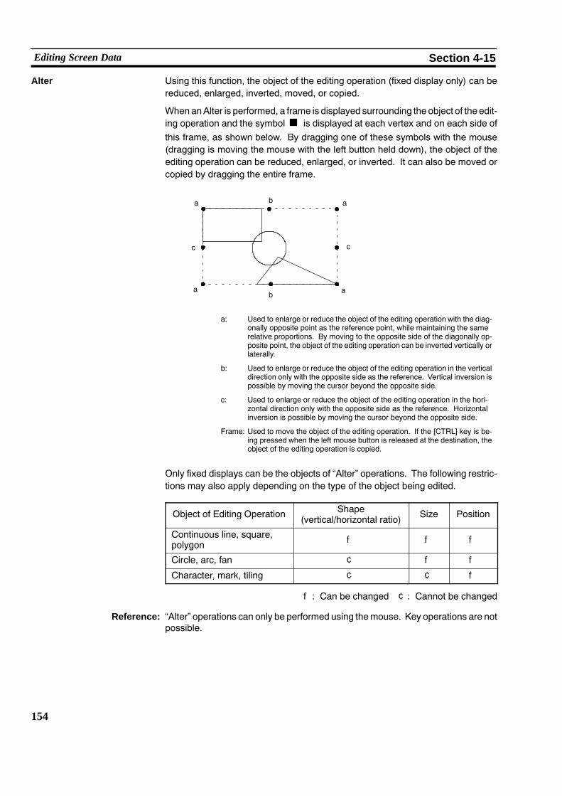
154
Editing Screen Data Section 4-15
Alter Using this function, the object of the editing operation (fixed display only) can bereduced, enlarged, inverted, moved, or copied.
When anAlter is performed, a frame is displayed surrounding the object of the edit-ing operation and the symbol is displayed at each vertex and on each side ofthis frame, as shown below. By dragging one of these symbols with the mouse(dragging is moving the mouse with the left button held down), the object of theediting operation can be reduced, enlarged, or inverted. It can also be moved orcopied by dragging the entire frame.
a: Used to enlarge or reduce the object of the editing operation with the diag-onally opposite point as the reference point, while maintaining the samerelative proportions. By moving to the opposite side of the diagonally op-posite point, the object of the editing operation can be inverted vertically orlaterally.
b: Used to enlarge or reduce the object of the editing operation in the verticaldirection only with the opposite side as the reference. Vertical inversion ispossible by moving the cursor beyond the opposite side.
c: Used to enlarge or reduce the object of the editing operation in the hori-zontal direction only with the opposite side as the reference. Horizontalinversion is possible by moving the cursor beyond the opposite side.
Frame: Used to move the object of the editing operation. If the [CTRL] key is be-ing pressed when the left mouse button is released at the destination, theobject of the editing operation is copied.
a
ba a
ab
c c
Only fixed displays can be the objects of “Alter” operations. The following restric-tions may also apply depending on the type of the object being edited.
Object of Editing Operation Shape(vertical/horizontal ratio) Size Position
Continuous line, square,polygon f f f
Circle, arc, fan ¢ f f
Character, mark, tiling ¢ ¢ f
f: Can be changed ¢: Cannot be changed
Reference: “Alter” operations can only be performed using themouse. Key operations are notpossible.

155
Editing Screen Data Section 4-15
S Lateral enlargement
The circle does not change shape.
Note If a circle, arc, or fan which has been reduced in the vertical or horizontal directionand whose position has been changed is returned to its original size, it will not re-turn to its original position (in contrast, shapes which are modified while retainingtheir relative proportions can be returned to their original position by returningthem to their original size).
S Enlargement while retaining relative proportions
S Inversion
Dragged to theopposite side
Procedure 1. Select “EDIT” from the initial editing menu.
2. Select “Alter” from the editing menu.
3. Select the object of the editing operation.
4. Perform modification by dragging a symbol or the frame.
To abort the operation, press the [Esc] key.

156
Editing Screen Data Section 4-15
Rotation This function rotates the object of the editing operation by 90_ in the clockwisedirection.
Rotation is performed with the center of the frame that encloses the object of theediting operation as the reference point. If a rotation operation would cause theobject of the editing operation to project beyond the edge of the screen, rotation isnot performed.
Only fixed displays can be the objects of “Rotate” operations. The following re-strictions may also apply depending on the type of object being edited.
Object of Editing Operation Rotation
Continuous line, square, polygon, circle, arc, fan, tiling f
Character, mark ¢
f: Can be changed ¢: Cannot be changed
Procedure 1. Select “EDIT” from the initial editing menu.
2. Select “Rotate” from the editing menu.
3. Select the object of the editing operation.
4. Check the message and press the key.
To abort the operation, press the [Esc] key.

157
Editing Screen Data Section 4-15
Batch Changing Colors (NT30C and NT60C only)
Used to change the colors for specified data within a specified area in a batch.
Procedure 1. Select “EDIT” from the initial editing menu.
2. Select “ColChg” from the editing menu.
3. Select the objects subject to the batch color change operation.
However, note that a specification to change to transparent color will be ig-nored if it applies to a part of the image for which transparent color cannot beused.
4. Specify the color change method and press the key.
5. Check the message and press the key.
" To abort the batch color change, press the [Esc] key.
Quitting Editing Select whether to quit after saving the result of editing or to quit without saving theresult of editing.
Procedure 1. Press the [Esc] key while the editing menu is displayed.
2. Check the message.
S Press the key to quit after saving the result of editing.
S Press the [Space] key to quit without saving the result of editing (the statusbefore editing started will be re-established).

158
Editing Screen Data Section 4-15

159
SECTION 5Creating Marks, Images, and Library Data
It is possible to create customized characters and symbols called “marks” and display them on the screen.
Marks can be treated in the same way as wide font characters: they can be displayed at various scales of enlargement andattributes can be set for them.
They can also be used in the creation of image data and library data for display on the screen.
5-1 Marks 160. . . . . . . . . . . . . . . . . . . . . . . . . . . . . . . . . . . . . . . . . . . . . . . . . . . . . . . . . . . . . . . . . . . . . .5-1-1 Mark Creation Procedure 160. . . . . . . . . . . . . . . . . . . . . . . . . . . . . . . . . . . . . . . . . . . . . . . . .5-1-2 Mark Creation Screen 160. . . . . . . . . . . . . . . . . . . . . . . . . . . . . . . . . . . . . . . . . . . . . . . . . . . .5-1-3 Mark Creation Functions 161. . . . . . . . . . . . . . . . . . . . . . . . . . . . . . . . . . . . . . . . . . . . . . . . .
5-2 Images 164. . . . . . . . . . . . . . . . . . . . . . . . . . . . . . . . . . . . . . . . . . . . . . . . . . . . . . . . . . . . . . . . . . . . .5-2-1 Procedure for Image Creation 165. . . . . . . . . . . . . . . . . . . . . . . . . . . . . . . . . . . . . . . . . . . . .5-2-2 Image Editing Operations 166. . . . . . . . . . . . . . . . . . . . . . . . . . . . . . . . . . . . . . . . . . . . . . . . .
5-3 Library Data 171. . . . . . . . . . . . . . . . . . . . . . . . . . . . . . . . . . . . . . . . . . . . . . . . . . . . . . . . . . . . . . . . .5-3-1 Procedure for Library Data Creation 171. . . . . . . . . . . . . . . . . . . . . . . . . . . . . . . . . . . . . . . .5-3-2 Library Editing Operations 172. . . . . . . . . . . . . . . . . . . . . . . . . . . . . . . . . . . . . . . . . . . . . . . .

160
Marks Section 5-1
5-1 MarksThis section describes how to create customized characters and symbols and dis-play them on the screen.
Marks can be created in three sizes: 16x16, 32x32, or 64x64 dots.
When using an NT20S, NT20M, NT600S, or NT600M, only 16x16 dot marks canbe created.
5-1-1 Mark Creation ProcedureThe procedure for creating marks is as follows.
Procedure 1. Press the [F9] (Mark) key on the “Screen Selection” screen.
2. Specify the size of the mark to be created.
Three sizes are available: 16x16, 32x32, and 64x64 dots.
" An existing mark can be copied by pressing the [F1] (Copy) key, specifying therange for the copy source by inputting a start point and end point, and thenspecifying the position of the copy destination.
An existing mark can be moved by pressing the [F2] (Move) key, specifying therange for the move source by inputting a start point and end point, and thenspecifying the position of the move destination.
An existing mark can be deleted by pressing the [F3] (Delete) key and specify-ing the range by inputting a start point and end point.
3. Move the cursor to specify the position at which the mark is to be registeredonce it has been created.
4. Create the mark graphic in the creation area.
5. Press the [F8] key to register the created mark.
6. Press the [Esc] key to quit mark creation.
5-1-2 Mark Creation ScreenMarks are created on the mark creation screen.
Up to 224 marks of the 16x16 dot size can be registered.
Since the same registration area is used for each mark size, 32x32 dot marksoccupy four times the area that 16x16 dot marks do, and 64x64 dot marks occupysixteen times the area that 16x16 dot marks do.

161
Marks Section 5-1
<Example: 16x16 dot screen>
S Reference Area: Area used to display other marks for reference during markcreation.
S Creating Area: Area used for creating marks with dot data.
5-1-3 Mark Creation FunctionsDot Operations
S Dot display/deletion
When the [Shift] key is pressed, a dot is displayed at the cursor position.
If the [Shift] key is pressed while the cursor is located over a displayed dot, the dotwill be deleted.
When using a mouse, click with the left button to display dots and click with theright button to delete them.
S Continuous display or deletion of dots
To display or delete a continuous line of dots, move the cursor by pressing one ofthe arrow keys while holding down the [Shift] key.
S Screen rotation
Each time the [� ] or [� ] key is pressed while holding down the [Alt] key and [Shift]key, the mark displayed on the screen will be rotated by 90.
Alt Shift �+ + Alt Shift �+ +

162
Marks Section 5-1
S Moving the screen
Pressing one of the arrow keys while holding down the [Alt] key will move the markdisplayed on the screen.
Creating screenAlt �+ � �
�
�
Alt �+
Alt �+
Alt �+
Functions of the Function Keys
[Cha Ref] [F1] Character reference. . .
Used to display an input character in the reference area.
(1) Press the [F1] (Cha Ref) key.
(2) Input the character to be used for reference (one wide font character or a max-imum of two normal font characters).
(3) Press the key: the character will be displayed.
[Mk Ref] [F2] Mark reference. . .
Used to display an existing mark in the reference area.
(1) Press the [F2] (Mk Ref) key.
(2) Locate the cursor on the mark in the mark list window that is to be displayed.
(3) Press the key: the character will be displayed.
[Copy] [F3] Area copy. . .
Used to copy the dots in a specified area into the creating area.
(1) Press the [F3] (Copy) key.
(2) Specify the start point and end point of the area to be copied.
(3) Move the area to the copy destination and press the key: the dots will becopied.
[RCopy] [F4] Copy from the reference area. . .
Used to copy the dots in a specified area of the reference area to the creating area.
(1) Press the [F4] (RCopy) key.
(2) Specify the start point and end point of the area within the reference area thatis to be copied. Specify diagonally opposite points to specify a rectangulararea.
(3) Move the area to the copy destination within the creating area and press thekey: the dots will be copied.

163
Marks Section 5-1
[Set] [F5] Set dots in a specified area. . .
Used to set (display) all the dots within a specified area.
(1) Press the [F5] (Set) key.
(2) Specify the start point and end point of the area in which the dots are to be set.
Specify diagonally opposite points to specify a rectangular area.
(3) Press the key: the dots inside the specified area will be set.
[Clear] [F6] Reset dots in a specified area. . .
Used to reset (clear) all the dots within a specified area.
(1) Press the [F6] (Clear) key.
(2) Specify the start point and end point of the area in which the dots are to becleared.
Specify diagonally opposite points to specify a rectangular area.
(3) Press the key: the dots inside the specified area will be cleared.
[Inv.] [F7] Invert dots. . .
Used to invert the display of all the dots within a specified area: displayed dots arecleared and cleared dots are displayed.
(1) Press the [F7] (Inv.) key.
(2) Specify the start point and end point of the area in which the dots are to becleared.
Specify diagonally opposite points to specify a rectangular area.
(3) Press the key: the dots inside the specified area will be inverted.
[Save] [F8] Register a mark. . .
Used to register a mark that has been created.
Displaying Marks Marks can be displayed in either of the two following ways.
(1) Specification during character input
If the [F3] (Mark) key is pressed when inputting characters or a label, a mark canbe selected from the mark selection screen (only 16x16 dot marks can be se-lected).
It is possible to use marks in combination with characters.
Mark data is displayed as data in the character input field. On the “Edit” screen, theactual mark is displayed, taking the left bottom extremity of the mark as the origin.
(2) Specification from the Fixed Display Menu
On selecting “Mark” from the fixed display menu and specifying a size, a mark canbe selected from the mark selection screen.
For details on the operating procedure, see “Inputting Marks” (p.82).

164
Images Section 5-2
5-2 ImagesImage data is created in dot units and can be displayed on the screen. Marks andsymbols can be created and registered.
Images are handled in the same way as characters and marks.
Illustrations and figures can be read with an image scanner.
Images can only be used when using an NT30, NT30C, NT610G, or NT610C.
Reference: The sizes of images that are not reduced are as follows, depending on the widthand height of the image area.
NT610G : {(width + 7)$8} x height + 558 bytes
NT30, NT30C, NT610C : [{(width + 7)$8} x height + 48] x 3 + 510 bytes
(“$” indicates a division operation in which decimal fractions are discarded.)
When an image is reduced, the size will be smaller that indicated above. The re-duction scale will differ according to the nature of the image data.

165
Images Section 5-2
5-2-1 Procedure for Image CreationImage data is created on the screen in dot units using mouse and key operations,then the required area is specified and the image registered. Up to 224 images canbe registered.
Procedure 1. Select “Image & Lib” on the “Screen Selection” screen.
2. Locate the cursor at the code (from FE20 to FEFF) of the image to be createdand press the key.
" Use [Shift] + [�] or [Shift] + [�] to move the bar cursor to the previous or nextcode for which there is data.
Use the [� ]/[� ] keys to switch between image and library data.
Press the [Tab] key to display the code input field.
The data of a code for which data already exists can be deleted by pressing the[F1] (Delete) key and then specifying that code.
The data of a code can be copied by pressing the [F2] (Copy) key and thenspecifying the copy source code and the copy destination code.
Existing comments can be changed by pressing the [F6] (Commnt) key andinputting the required characters.
3. Draw image data on the screen using the mouse and keys (see “Image EditingOperations” on the next page).
4. Press the [Esc] key to quit image creation.
On quitting, specify “Confirm”.
5. Select whether or not to reduce the saved data.
" Displaying reduced image data takes more time than displaying image datathat is not reduced.
6. Specify the area that is to be saved as the image data.
locate the cross-hair cursor at the start point and end point of the area andpress the key at each.
7. Input a comment.
This is a memo that indicates the nature of the image data.

166
Images Section 5-2
5-2-2 Image Editing OperationsOn selecting an image code, the image editing screen shown below is displayed.
(a)
(c) (d)
(b)
(a) Image editing screen: This is the screen on which images are created. Nogrid is displayed.
(b) Image editing menu: This is the menu for editing images.
(c) Code: This is the code of the image that is currently beingedited.
(d) Remaining capacity: The data size (number of bytes) that can still be usedfor image creation.
S Color Mode
If using an NT30C or NT610C, the color mode (2 colors or 8 colors) can bechanged by selecting “COL MODE” from the image editing menu.

167
Images Section 5-2
Enlarged Display A part of the image display screen can be displayed enlarged by selecting“LOUPE” from the image editing menu: this allows editing in dot units.
S Key Operations
[Home] key: Used to shift the help message window.
Arrow keys: Used to move the cursor (the cursor can be movedmore quickly by pressing an arrow key while holdingdown the [Shift] key, but this operation can only be usedin the box tiling mode).
[Ctrl] + arrow keys: Used to shift the enlarged display window (it can bemoved faster by pressing the [Shift] key also).
[F1] key: Used to change the enlargement scale (2x, 4x, 8x)
[F2] key: Used to change the drawing mode (locus, box tiling)
The enlarged display window can also be moved by locating the cursor inside it,pressing the key, then moving the cursor and pressing the key again.
S Drawing method
On this screen, images are drawn with dots in the manner described below. If us-ing an NT30C or NT610C, the color used for the help message window has to beselected (this selection can be made using the numeric keys).
[Locus mode]
Key operation: Dots are drawn by moving the cursor while holding downthe [Shift] key.
Mouse operation: Dots are drawn by dragging the mouse while holding downthe left mouse button.
[Box tiling mode]
Key operation: Press the key at the diagonally opposed corners of thearea (rectangle) to be tiled.
Mouse operation: Click the left mouse button at the diagonally opposed cor-ners of the area (rectangle) to be tiled.

168
Images Section 5-2
Procedure 1. Select “LOUPE” from the image editing menu.
2. Carry out drawing in dot units.
3. Press the [Esc] key to quit the enlarged display.
Drawing Operations Using the Image Editing Menu
Functions are selected from the image editing menu in order to carry out drawing.
The following graphic elements can be used:
Points, lines, locus, circles, ellipses, squares
In the case of circles, ellipses and squares, it is also possible to select normal orinverted displays.
When using an NT30C or NT610C, the color can also be specified.
Ellipses can only be drawn as images.
S Points
Key operation: Press the key.
Mouse operation: Click the left mouse button.
S Lines
Key operation: Press the key at the start point and end point.
Mouse operation: Click at the start point and end point.
S Locus
Key operation: Locus drawing is not possible with key operations.
Mouse operation: Drag the mouse while holding down the left mouse button.
S Circles/ellipses
Key operation: Press the key at diagonally opposed points to draw a circleor ellipse that just makes contact with the inside of the rectan-gle defined by these points.
Mouse operation: Click at diagonally opposed points to draw a circle or ellipsethat just makes contact with the inside of the rectangle definedby these points.
S Squares
Key operation: Press the key at the diagonally opposed points.
Mouse operation: Click at the diagonally opposed points.

169
Images Section 5-2
Reading Existing Image Data
Existing image data can be read onto the image editing screen.
Procedure 1. Select “READ FIL” from the image editing menu.
2. Locate the bar cursor on the code of the image to be read and press thekey.
3. A box that indicates the size of the image will be displayed.
Move this box to the required display position and press the key.
Reading Bit map Files (.BMP)
Bit map files can be read as image data.
However, only bit map files that comply with the following conditions can be read:
S The bit map must be monochrome, 16-color, or 256-color.
S The data must not be compressed.
Note 1. PCX format bit map files cannot be read.
2. When 16-color and 256-color bit map files are read, the number of colors isreduced to eight. This means that the rendition of color will not be the same asin the original file.
Procedure 1. Press the [F7] (Image & Lib) key on the “Screen Selection” screen.
2. Select the image code (range: FE20 to FEFF).
3. Select “READ FIL” (read file) from the image editing menu.
4. A prompt requesting the file name of the bit map file will appear: specify thepath and enter the file name (see the example below). An extension must bespecified.
Example
C:\WIN\PUPPY.BMP<ENTER>
5. After reading, the data can be edited as image data.
Storing Screen Data in Files
Existing screen data can be converted to the bit map file format and stored as a file.
Procedure 1. Locate the bar cursor on the screen to be converted to bit map data, press the[F10] key, then press the [F3] (Co File) key.
2. Follow the screen messages to create a file for the screen data. The file namewill be registered in the format shown below.
NT612G: NTGVVVV.BMP
NT610C: NTCVVVV.BMP
* The screen number is entered in the section represented as VVVV.

170
Images Section 5-2
Copying Images on the Image Editing Screen
Images can be copied on the image editing screen.
Since it is possible to repeatedly specify copy destinations for the same copysource, moving the mouse with the mouse button held down has the effect of usinga thick pen or eraser.
Procedure 1. Select [COPY] from the image editing menu.
2. Press the key with the cursor on the diagonally opposite point of the copysource.
3. Move the cursor to the copy destination and press the key.
The image will be copied. Other copy destinations can now be specified.
" Press the [Esc] key to quit copying.
" Continuous copying is possible by moving the mouse with the button helddown.
Displaying Images Images can be displayed in either of the following two ways.
(1) Specification during character input
If the [F4] (Image) key is pressed when inputting characters or a label, animage can be selected from the image selection screen.
It is possible to use images in combination with characters and marks.
Image data in a character input field is displayed as a [I] mark. In image edit-ing, the real image is displayed, taking the left bottom extremity of the imageas the origin.
Display on “Edit” screen:
Image :
Character input field : A B I D E A B D E
The following specifications are not valid for imagedisplays:Scales, smoothing, display attributes
(2) Specification on the initial editing screen
Selecting “Image & Lib” from the initial editing screen enables selection ofimages from the image/library selection screen (the image codes are FE20 toFEFF).
For details on the procedure, see 4-11 “Inputting Image and Library Data”(p.141).
Images can also be set for the ON and OFF codes of image/library lamps. Fordetails, see “Setting Image/Library Lamps” (p.102).
WARNING

171
Library Data Section 5-3
5-3 Library DataTwo or more graphics can be registered together as library data. Complex graph-ics need only be created once, after which they can be used repeatedly.
Library data can only be used when using an NT30, NT30C, NT610G, or NT610C.
The following codes can be used for library data:
FA20 to FAFF, FB20 to FBFF, FC20 to FCFF, FD20 to FDFF (896 items).
5-3-1 Procedure for Library Data CreationLibrary data is created by registering two or more graphics created on the libraryediting screen collectively under one code. Up to 896 library data can be regis-tered.
Procedure 1. Select “Image & Lib” on the “Screen Selection” screen.
2. Locate the cursor at the code of the library data to be created and press thekey.
" Use [Shift] + [�] or [Shift] + [�] to move the bar cursor to the previous or nextcode for which there is data.
Use the [� ]/[� ] keys to switch between image and library data.
Existing comments can be changed by pressing the [F6] (Commnt) key andinputting the required characters.
Press the [Tab] key to display the code input field.
The data in a code for which data already exists can be deleted by pressing the[F1] (Delete) key and then specifying that code.
The data in a code can be copied by pressing the [F2] (Copy) key and thenspecifying the copy source code and the copy destination code.
3. Draw the library data on the screen using the mouse and keys (see “LibraryEditing Operations” on the next page).
4. Press the [Esc] key to quit library data creation.
On quitting, specify “Confirm”.
5. Specify the area that is to be saved as the library data.
Regardless of the environmental settings (tool settings for the “Edit” screen),only graphics that are completely contained within the specified area will beregistered.
Locate the cross-hair cursor at the start point and end point of the area andpress the key at each.
6. Input a comment.
This is a memo that indicates the nature of the library data.

172
Library Data Section 5-3
5-3-2 Library Editing OperationsOn selecting a library code, the library editing screen shown below is displayed.
(a)
(c)
(b)
(a) Library editing screen: This is the screen on which library data is created.
(b) Library editing menu: This is the menu for editing library data.
(c) Code: This is the code of the library data that is currentlybeing edited.
Drawing Operations in the Library Editing Menu
Functions are selected from the library editing menu in order to carry out drawing.
The following graphic elements can be used. All of them are fixed display graph-ics. For details on the drawing methods, see the relevant pages of 4-3 “CreatingFixed Displays”.
Character input (fixed display) (p.80)
Marks (display) (p.82)
Continuous lines (p.84)
Squares (p.86)
Polygons (p.88)
Circles/Arcs (p.90)
Fans (p.92)
Tiling (p.93)
Also see the relevant pages of 4-14 “Editing Screen Data” for details on editing(p.150) and environmental settings (p.59).

173
Library Data Section 5-3
Reading From Existing Screen Data
Existing screen data can be read onto the library editing screen.
The only data that can be read is fixed displays on thespecified screen.
Reference: Read graphics are overlapped with any graphics that are already present on thelibrary editing screen, leaving these existing graphics in place.
Procedure 1. Select “READ SCR” from the library editing menu.
2. Locate the bar cursor on the code of the screen from which the graphic is to beread and press the key.
Displaying Library Data Use the following method to display library data.
Select “Image & Lib” from the initial editing screen to allow select of library datafrom the image/library selection screen (the library codes are FA20 to FAFF, FB20to FBFF, FC20 to FCFF, and FD20 to FDFF).
For details on the procedure, see 4-11 “Inputting Image and Library Data” (p.141).
Library data can also be set for the ON and OFF codes of image/library lamps. Fordetails, see “Setting Image/Library Lamps” (p.102).
WARNING

174
Library Data Section 5-3

175
SECTION 6Printing Data
Various types of data can be printed in file units or in screen data units.
6-16-1-1 Things that can be Done Using the Data Printing Function 176. . . . . . . . . . . . . . . . . . . . . . .6-1-2 Printing from the “File Selection” Screen 178. . . . . . . . . . . . . . . . . . . . . . . . . . . . . . . . . . . .6-1-3 Printing from the “Screen Selection” Screen 180. . . . . . . . . . . . . . . . . . . . . . . . . . . . . . . . . .
176
Printing Data Section 6-1
6-1-1 Things that can be Done Using the Data Printing FunctionVarious data relating to the support tool, such as screen data and the conditions ofuse of memory tables, can be printed out at a printer and checked.
S Specifiable output destinations
Any of the following three output destinations can be specified:
Printer: Screen images, various settings, etc., can beprinted out at a printer.
File (specify the file name): Various settings and other data can be output asa DOS text file. However, screen images cannotbe output to a file.
Display: Screen images, various settings and other data,can be displayed on the screen.
S Types of data that can be displayed
Printing can be initiated in one of two ways: by selecting “Print” on the “FileSelection” screen or by selecting “Print” on the “Screen Selection” screen. Thedata that can be printed differs according to the method used.
S When “Print” is selected on the “File Selection” screen
(1) Print out of the file list
(2) Print out of the screen list
(3) Print out of screen images
(4) Print out of cross-references (the conditions of use of memory tables)
(5) Print out of display history records received from the PT
(6) Print out of the mark list
(7) Print out of image/library data
S Cannot be specified with an NT20S, NT20M, NT600S, or NT600M
(8) Printout of direct connection information (only when using direct connection)
The mark list can only be output to the printer.
S When “Print” is selected on the “Screen Selection” screen
The following information can be specified, in single screen units.
(1) Screen images
(2) Color printing (NT30C and NT610C)
(3) Detailed information
Before attempting printing, make sure that the printer is connected and thatthere is paper in the printer.

177
Printing Data Section 6-1
Reference: S The environmental settings (tool settings for the “Edit” screen) determine wheth-er or not lamp/touch switch numbers, memory table numbers, and image/librarynumbers are printed or not.
S The type of printer and the presence or absence of a sheet feeder are set in the“Tool Settings” (see p.22).

178
Printing Data Section 6-1
6-1-2 Printing from the “File Selection” ScreenUse the following method to specify printing from the “File Selection” screen.
Procedure 1. Locate the bar cursor on the file to be printed.
2. Press the [F3] (Print) key.
3. Locate the bar cursor on the data to be printed.
S Print File List: Select to print the set memory, memory used,etc., for all files.
S Print Screen List: Select to print the screen numbers, comments inscreens, etc.
S Print Screen: Select to print images or other data in the screenin a file.
Set the following settings:
S Printing/non-printing of screen images
S Method for printing color (NT30C andNT610C) ... No / Imitation / 8 colors
(“Imitation” is printing in monochrome with 8grayscale levels).
S Printing/non-printing of detailed information
S Print Cross-References: Select to print numeral memory tables, charac-ter-string memory tables, and the conditions ofuse of bits.
Set the following settings:
S Memory TablePrint the conditions of use of memory tables.
S BitPrint the conditions of use of bits.

179
Printing Data Section 6-1
S AllPrint the conditions of use of all memorytables.
S Use Data onlyPrint only the part of the file used for screendata.
S Print Display History File: Select to print the display history record data re-ceived from the PT.
Input the file whose display history record data isto be printed.
S Print Mark List: Select to print a list of marks.
S Print Image/Library List: Select to print a list of image data and librarydata. This list can only be printed out when us-ing an NT30, NT30C, NT612G, or NT610C.
S Print Direct Access Info.: Select to print the direct connection information.
Set the following settings:
S AllPrint all direct connection information.
S Use Data onlyPrint only the specified direct connection in-formation.
(4) Specify the output destination and press the key.
Depending on the data to be printed, further settings may be necessary.
When the marks list is printed “Print Mark List” is not displayed.
(5) Check the printer and press the key.
The data will be printed.
Press the [Esc] key to stop printing.

180
Printing Data Section 6-1
6-1-3 Printing from the “Screen Selection” ScreenUse the following method to specify printing from the “Screen Selection” screen.
Procedure 1. Locate the bar cursor on the screen number whose data is to be printed.
If the screen data of more than one screen is to be printed, “mark” each of therelevant screen numbers.
" For details on using the mark function, see 3-5 “Screen Selection” Screen(p.31).
2. Press the [F3] (Print) key.
3. Specify the output destination.
4. Specify the printing format.
S Scr Image: Specify whether or not the screen image is to be printed as itis.
S Col Print: If using an NT610C, specify the method that will be used toprint color (“Imitat” means printing in monochrome with 8grayscale levels).
S Detl Info: Specify whether or not to print detailed information relating tothe screen.
5. Check the printer and press the key.
The data will be printed.
Press the [Esc] key to stop printing.
<Restrictions on data printing>
S If there is no data for an item, nothing will be printed.
S Up to 62 lines can be printed on one page.
S Up to 32 character data can be printed.
S If continuous screens or overlapping screens are printed with “No” set in the de-tailed information printing settings, only the child screen numbers will be printed.
S If continuous screens are printed with “Yes” set in the detailed information print-ing settings, the screen image and child screen number of the child screen speci-fied as number one will be printed.
S If overlapping screens are printed with “Yes” set in the detailed information print-ing settings, the screen image and child screen numbers will be printed.

181
Printing Data Section 6-1
NT30C and NT610C Screen Data Printing Example
Shown here is an example of screen data printing with an NT610C. Printing is car-ried out in the same way when using an NT30C.
In this example, the screen includes black characters on a white background, andsquares colored with all the available colors: the results of printing with “Imitat” and“No” selected for “Col Print” are shown below.
Col Print: Imitat
BLACK BLUE RED MAGENTA GREEN CYAN YELLOW WHITE
BLACK BLUE RED MAGENTH GREEN CYAN YELLOW WHITE
Background: black
Background: white
Col Print: No
BLACK BLUE RED MAGENTA GREEN CYAN YELLOW WHITE
BLACK BLUE RED MAGENTA GREEN CYAN YELLOW WHITE
When “No” is selected, neither the tiling nor the inversion of the graphics areshown and only the outlines are printed.

182
Printing Data Section 6-1

183
SECTION 7Data Communication
This chapter describes how screen data created using the support tool can be sent to the PT or written to a memory board, andhow data such as screens and display histories received from the PT can be communicated.
7-1 Preparation and Procedure for Data Communication with the PT 184. . . . . . . . . . . . . . . . . . . . . . . .7-2 Transmitting Data 188. . . . . . . . . . . . . . . . . . . . . . . . . . . . . . . . . . . . . . . . . . . . . . . . . . . . . . . . . . . .7-3 Receiving Data 190. . . . . . . . . . . . . . . . . . . . . . . . . . . . . . . . . . . . . . . . . . . . . . . . . . . . . . . . . . . . . .
7-3-1 Data Reception 190. . . . . . . . . . . . . . . . . . . . . . . . . . . . . . . . . . . . . . . . . . . . . . . . . . . . . . . . .7-3-2 Reception of Display History Records 192. . . . . . . . . . . . . . . . . . . . . . . . . . . . . . . . . . . . . . .

184
Preparation and Procedure for Data Communication with the PT Section 7-1
7-1 Preparation and Procedure for Data Communicationwith the PT
Screen data created using the support tool, and mark and memory table informa-tion, etc., can be transferred to the PT data memory. It is also possible to receivevarious types of data and display history records from the PT and save them.
Caution: When using an NT30, NT30C, NT612G, or NT610C, data is communicated in fileunits. Communication in screen units is not possible.
Connection to the PT Connect the PT and personal computer with an RS-232C connecting cable.
Connect this cable to the tool interface at the PT side and to the RS-232C interfaceat the personal computer side. Note that this connection with the PT is establishedonly for data communication; it is not usually necessary to make this connection.
S Connection method
Make the connection with the RS-232C cable in the manner shown below.
Connection to an NT20M/NT20S
Connection to an NT2000M

185
Preparation and Procedure for Data Communication with the PT Section 7-1
Connection to an NT600M/NT600S/NT612G/NT620S/NT620C
Connection to an NT30/NT30C
Connection to an NT610C
S Connecting cable
Make the connecting cable by referring to Appendix A “Connecting Cable Specifi-cations”.

186
Preparation and Procedure for Data Communication with the PT Section 7-1
Communication Speed Select the communication speed for communication with the PT by setting “Com-munication Mode” on the “Tool Settings” screen.
Setting “Hspeed” for this setting will enable high-speed data transfer.
If the communication environment is unfavorable or communication errors occur,set “Stndrd” for low-speed communication so that the data will be communicatedreliably.
Reference: Presented below are OMRON’s measurements of the time taken to transfer theentire capacity of the image memory when transfer is in the “Hspeed” mode. Usethese as a guide to data communication times.
S When using a capacity of 512 Kbytes: 5 min. 5 sec.
S When using a capacity of 1 Mbyte: 9 min. 30 sec.
Communication in the “Stndrd” mode takes approximately twice as long as com-munication in the “Hspeed” mode.
Tool Settings When Communicating With an NT20S or NT600S
When using an NT20S or NT600S, the combination of tool settings that allowscommunication with the support tool depends on which model is used.
Set the tool settings for communication with an NT20S or NT600S correctly by re-ferring to the table below.
S When using an NT20S
Tool Settings Model
“PT Type”Setting Direct Access NT20S-ST121 NT20S-ST121-V1/
ST122-V1 NT20S-ST128
20M Not used x x x
20S Not used x x f
20M Ver.4 ff in NT20M com-
patible mode x
20S Ver.4 x f x
20S Ver.5 x f x
f: possible x: not possible
S When using an NT600S
Tool Settings Model
“PT Type”Setting Direct Access NT600S-ST121/
ST211
NT600S-ST 121-V1/ST211-V1 direct
connection
NT600S-ST121-V1/ST211-V1 direct
connection
600M Not used x x x
600S Not used x x f
600M Ver.4f in NT600M
compatiblemode
f in NT600Mcompatible mode x
600S Ver.4 f f x
600S Ver.5 x f x
f: possible x: not possible

187
Preparation and Procedure for Data Communication with the PT Section 7-1
Types of Data Communication with Each PT Model
There are two methods for data communication, as follows:
S Data communication in file units executed using the “File Selection” screen
S Data communication in screen units executed using the “Screen Selection”screen.
Whether or not data communication in file units or screen units can be used isshown in the table below for each PT model.
PT Model File Units Screen Units
NT20S f ST121: xST121-V1: n*ST122-V1: n*ST128: f
NT20M/NT2000M f f
NT600S f n*
NT600M f f
NT30 f x
NT30C f x
NT612G f x
NT610C f x
NT620S f x
NT620C f x
f: possible n: partly possible x: not possible
*: In the NT20S/NT600M compatible mode, simultaneous transmission of multi-ple screens and verification are not possible.
Procedure for Data Communication
Use the following procedure to make preparations at the PT and support tool sidesand execute data communication.
Return to “Run Mode”
<Procedure at PT side>
Connect to the support tool
<Procedure at the support tool side>
Display the system menu
Select “Transmit Mode”
Connect to the PT
Execute the transmit or receive function
Transmission or reception
Reference: For details on the operations at the PT side, refer to the operation manual for thePT.

188
Transmitting Data Section 7-2
7-2 Transmitting DataThis is the procedure for transmitting data such as image data or memory tabledata to the PT, and writing it into the flash memory type data memory of the PT.
There are two methods for transmitting data, as follows:
S Selecting a file from the “File Selection” screen and transmitting it to the PT.
S Selecting a screen from the “Screen Selection” screen and transmitting it to thePT.
Transmitting Data in File Units
Select a file from the “File Selection” screen and transmit it to the PT.
Procedure 1. Set the PT to the “Transmit Mode”.
" Check that the write switch of the screen data memory board is released.
2. Locate the bar cursor on the file to be sent on the “File Selection” screen.
3. Press the [F6] (Tmx.) key.
4. A message will be displayed for the purpose of confirmation.
Check the message and press the key.
" Press the [Esc] key to abort data transmission.
5. Data transmission will start.
On completion of the transmission, the message “Data successfully trans-mitted.” will be displayed.
" Press the [Esc] key to stop transmission part way through.
Reference: When data transmission has been aborted part way through, initialize the imagedata memory: do this by using the DIP switch on the PT.
For details, refer to the operation manual for the PT.
Also initialize the image data memory by this means if data transmission isstopped due to trouble.

189
Transmitting Data Section 7-2
Data Transmission in Screen Units
Whether or not data communication in screen units is possible depends on the PTmodel used. For details, see “Types of Data Communication with Each PT Model”(p.185).
Procedure 1. Set the PT to the “Transmit Mode”.
Check that writing to the screen data memory is possible.
2. Locate the bar cursor at the screen to be transmitted on the “Screen Selection”screen.
When transmitting multiple screens, “mark” the appropriate screens. For de-tails on using the marking function, see 3-5 “Screen Selection Screen” (p.31).
If transmitting numeral or character-string memory table data only, it does notmatter where the bar cursor is.
3. Press [F10] (Next), then [F6] (Tmx).
4. Specify either “Screen Data” or “Memory Table” as the data to be transmitted,and press the key.
5. Specify whether or not verification (writing check) is to be executed, then pressthe key.
6. A confirmation message will be displayed.
Check the message and press the key.
To abort transmission, press the [Esc] key.
7. Transmission will start.
On completion of transmission, the message “Data successfully transmitted”is displayed.
To abort transmission part way through, press the [Esc] key.
Reference: After aborting data transmission part way through, initialize the screen datamemory. To do this, perform forced initialization with the DIP switch on the PT. Fordetails, refer to the Operation Manual for the PT. Take the same measures if datatransmission is discontinued due to trouble.

190
Receiving Data Section 7-3
7-3 Receiving DataThis is the procedure for receiving screen data, memory table data, display histo-ries, etc., from the PT and storing this data as support tool files, and for receivingdata in screen units, and writing it to the screen data of the support tool.
7-3-1 Data ReceptionUse the following procedure to receive all the data in the data memory and write itto a file.
There are two methods for receiving data, as follows:
S Receiving all the data in the PT’s data memory and writing it to a file.
S Receiving data in screen units and writing it to the support tool.
Receiving Data in File Units
Procedure 1. Set the PT to the “Transmit Mode”.
2. Display the “File Selection” screen.
It does not matter where the bar cursor is.
3. Press the [F7] (Rcv.) key.
4. Input the file name of the file to which the received data is to be written.
5. Press the key.
File reception will start.
" If a file that already exists is specified, a message asking whether or not the fileis to be overwritten will be displayed. If you do not want to overwrite it, press the[Esc] key.
" Press the [Esc] key to stop reception part way through.
On completion of reception, the message “Data successfully transmitted” willbe displayed.

191
Receiving Data Section 7-3
Receiving Data in Screen Units
Whether or not it is possible to execute data reception in screen units depends onthe PT model. For details, see “Types of Data Communication with Each PT Mod-el” (p.185).
Procedure 1. Set the PT to the “Transmit Mode”
2. Display the “Screen Selection” screen.
It does not matter where the bar cursor is.
3. Press the [F10] (Next) key, then press the [F7] (Rcv.) key.
4. Specify “Screen Data” or “Memory Table” as the type of data to be received,then press the key.
5. Specify the screen number at the PT side and the screen number at the sup-port tool side, pressing the key after each specification.
6. A message will displayed for the purpose of confirmation.
Check the message and press the key.
" Press the [Esc] key to abort reception.
7. Reception will start.
On completion of reception, the message “Data successfully transmitted” willbe displayed.
" Press the [Esc] key to stop reception part way through.

192
Receiving Data Section 7-3
7-3-2 Reception of Display History RecordsWhen a screen for which the “History” screen attribute is set is displayed during PToperation, the PT records this display in the display history record.
This display history record can be read using the support tool in order to analyzehow the screen is used or its frequency of display, for example.
Received files are saved in the DOS text format in the set data directory, and theextension “.G6L” is automatically assigned to them. The data directory is set in the“Tool Settings”.
The received data is stored in the order of the order of occurrence record and theorder of frequency record.
Reference: Received display history data can be printed out by selecting [F3] (Print) on the“File Selection” screen.
Procedure 1. Set the PT to the “Transmit Mode”.
2. Display the “File Selection” screen.
It does not matter where the bar cursor is.
3. Press the [F5] (Hist.) key.
4. Input the file name of the file in which the received display history record is tobe saved.
Specify a file name no longer than eight characters. Do not specify an exten-sion: the support tool will automatically assign the extension “.G6L” to the file.
5. Press the key to start file reception.
" If a file that already exists is specified, a message asking whether or not the fileis to be overwritten will be displayed.
Press the key to start reception. If you do not want to overwrite data, pressthe [Esc] key.
" To stop reception part way through, press the [Esc] key.
On completion of reception, the message “Data completely received” willbe displayed.

193
Connecting Cable Specifications Appendix A
APPENDIX AConnecting Cable Specifications
Tool Interface Connector SpecificationsThe following specifications apply to the connection between the PT and the sup-port tool (personal computer).
Pin No. Signal Name Meaning
1 FG Frame ground
2 SD Send data
3 RD Receive data
4 RS Request to send
5 CS Clear to send
9 SG Signal ground
Assembly of Connecting CablesWiring should be carried out in one of the following ways, depending on the type ofRS-232C connector.
25-pin Connector
Connector for peripheraldevices on PT body
Personal computer
Shielded wire
Use the following recommended products when making the connecting cable.
Name Model Remarks
Connector XM2D-2501 25-pin Made by OMRON
XM2A-0901 9-pin Made by OMRON
Connector hood XM2S-2511 25-pin Made by OMRON
XM2S-0911 9-pin Made by OMRON
Cable AWG28×5PIFVV-SB
Multi-core shielded cable Made byFujikura, Ltd.
CO-MA-VV-SB5P×28AWG
Multi-core shielded cable Made byHitachi, Ltd.

194
Connecting Cable Specifications Appendix A
9-pin Connector
Personal computer
Shielded wire
Connector for peripheraldevices on PT body
Use the following recommended products when making the connecting cable.
Name Model Remarks
Connector XM2D-0901 9-pin Made by OMRON
XM2A-0901 9-pin Made by OMRON
Connector hood XM2S-0911 9-pin Made by OMRON (Two)
Cable AWG28×5PIFVV-SB
Multi-core shielded cable Made byFujikura, Ltd.
CO-MA-VV-SB5P×28AWG
Multi-core shielded cable Made byHitachi, Ltd.

195
Error Messages Appendix B
APPENDIX BError Messages
The error messages that may be displayed while using the support tool, and theaction to take in response to them, are shown below.
Error Message Corrective Action
3,000 I/O comments registered. (Confirm)
No more can be registered.
If there unnecessary comments, delete them.
One screen exceeds 16 Kbytes. (Confirm) The maximum data size for one screen is 16 Kbytes. If there isunnecessary data, delete it (see 3-5 “Screen Selection Screen”on p.31).
Image/Library area exceeds 64 KBytes. (Confirm) Delete unnecessary data.
The number of bits for cross-referencinghas exceeded 3000. (Confirm)
If there is unnecessary screen data, delete it.
Not usable with this version. (Confirm)
Check usable functions and adjust the tool settings.
The current tool settings (“PT Model”, “Direct Access”) do notcorrespond with the specified function.
This file can’t be sent. (Confirm)
Check the tool settings and file (detailed info).
Files displayed in red cannot be transmitted. Match the toolsettings with the file to be transmitted.
Work directory disk capacity insufficient. (Confirm) Set the data in a directory with sufficient free area (1 MB orgreater)
Data directory disk capacity insufficient. (Confirm)greater).
Seek error detected. (Confirm) The disk is damaged, or the drive may be faulty. Either replacethe disk or inspect the disk drive
Disk is faulty. (Confirm)the disk or inspect the disk drive.
Sector not found. (Confirm) Initialize (format) the disk in DOS format before using it.
Check the direct access version. (Confirm) Adjust the tool settings to match the direct connection version ofthe selected file.
Error detected in the data (Confirm) Part of the data has been destroyed and it cannot be used as itis. Delete the data and create it again. Or, if there is backupdata, use that.
Disk may be broken. (Confirm) Replace the disk. If there is a backup disk, use that.
Disk is protected. (Confirm)[ G G : Retry G G : Abort ]
Try again after releasing the disk’s write protection.
Disk not ready. (Confirm)[ G G : Retry G G : Abort ]
Set the floppy disk correctly in the designated drive and tryagain.
Too many registered channels: correct to MAX value?( G G Yes/ G G Abort)
The number of registered counter words has been set to two ormore by a batch change operation: this is automatically cor-rected to one word (see “Batch Changing Bits and Words”,p.79).

196
Error Messages Appendix B
Error Message Corrective Action
PT memory capacity insufficient. (Confirm)
Expand the image memory.
Increase the size of the PT screen memory.
The PT image memory is an EEP-ROM. In the case of an EEP-ROM or EP-ROM or Flash ROM, deletedata in file units
The PT image memory is an EP-ROM.data in file units.
Check the combination of PT Type, (Confirm)Memory Size, and Direct Access settings.
Items displayed in red in the tool settings cannot be set.
Can’t read file. (Confirm) Either the disk is faulty, or data has been destroyed. Replacethe disk or delete the files and create them again If there is a
Can’t read screen data. (Confirm)the disk or delete the files and create them again. If there is abackup disk, use that.
Can’t read or write data. (Confirm)
Can’t save file. Input the data directory name in the tool settings correctly, thentry again.
Number of files is max. (Confirm)Number of data directory files exceeds max.
The maximum number of files that can be handled by the sup-port tool is 200. Delete unnecessary files (see 3-4 “File Selec-tion Screen” on p.26).
Data this support toolcan’t handle received.
Either the received data is destroyed, or the support tool you areusing is not compatible with the direct connection version of thedata If the same message is displayed even when the latest
ROM data that support toolcan’t handle received.
data. If the same message is displayed even when the latestsupport tool is used, create the data again.

197
Special Characters Appendix C
APPENDIX CSpecial Characters
English Character Codes
Pin 3 of SW1 must be ON to enable English language messages to use the follow-ing codes.
Example
Hex code is represented by 30, decimal code by 48, and character by0.
Code 20 and 32 in the table represents a space, as indicated by“SP”.

198
Special Characters Appendix C
*1
*1
*1
*1
*2
*3
*1 Used as the prefix for library data codes ( 2 bytes).
*2 Used as the prefix for image data codes ( 2 bytes).
*3 Used as the prefix for mark data codes ( 2 bytes).

199
INDEX
AAlarm 145. . . . . . . . . . . . . . . . . . . . . . . . . . . . . . . . . . . .
Alarm history 144. . . . . . . . . . . . . . . . . . . . . . . . . . . . .
Alarm list 144. . . . . . . . . . . . . . . . . . . . . . . . . . . . . . . . .
Allocated bit 75. . . . . . . . . . . . . . . . . . . . . . . . . . . . . . .
Allocated word 75. . . . . . . . . . . . . . . . . . . . . . . . . . . . .
Alter 154. . . . . . . . . . . . . . . . . . . . . . . . . . . . . . . . . . . . .
Arcs 90. . . . . . . . . . . . . . . . . . . . . . . . . . . . . . . . . . . . . .
Assembly of connecting cables 193. . . . . . . . . . . . . .
Attribute 62, 64. . . . . . . . . . . . . . . . . . . . . . . . . . . . . . . .
BBack-up 3. . . . . . . . . . . . . . . . . . . . . . . . . . . . . . . . . . . .
Background color 66. . . . . . . . . . . . . . . . . . . . . . . . . . .
Backlight OFF cancelling attribute 45. . . . . . . . . . . . .
Bar cursor 10. . . . . . . . . . . . . . . . . . . . . . . . . . . . . . . . .
Bar graph 117, 118. . . . . . . . . . . . . . . . . . . . . . . . . . . .
Basic color 66. . . . . . . . . . . . . . . . . . . . . . . . . . . . . . . .
Batch changing 79, 157. . . . . . . . . . . . . . . . . . . . . . . .
Bit map files 169. . . . . . . . . . . . . . . . . . . . . . . . . . . . . .
Bit memory table 144. . . . . . . . . . . . . . . . . . . . . . . . . .
Bit memory table setting 47, 72. . . . . . . . . . . . . . . . . .
Bits 75, 178. . . . . . . . . . . . . . . . . . . . . . . . . . . . . . . . . . .
Boundary color 66. . . . . . . . . . . . . . . . . . . . . . . . . . . . .
Box cursor 10. . . . . . . . . . . . . . . . . . . . . . . . . . . . . . . . .
Box tiling mode 167. . . . . . . . . . . . . . . . . . . . . . . . . . . .
Brkn line frame disp. 60. . . . . . . . . . . . . . . . . . . . . . . .
“Brkn-line grph intv” setting 127. . . . . . . . . . . . . . . . .
Broken line graph 117, 123. . . . . . . . . . . . . . . . . . . . . .
Bus mouse 2. . . . . . . . . . . . . . . . . . . . . . . . . . . . . . . . .
CCables 193. . . . . . . . . . . . . . . . . . . . . . . . . . . . . . . . . . .
Center of the screen 52. . . . . . . . . . . . . . . . . . . . . . . .
Centering 153. . . . . . . . . . . . . . . . . . . . . . . . . . . . . . . .
Cha ref 162. . . . . . . . . . . . . . . . . . . . . . . . . . . . . . . . . . .
Change comment 38. . . . . . . . . . . . . . . . . . . . . . . . . .
Change file title 30. . . . . . . . . . . . . . . . . . . . . . . . . . . .
Changing orders 139. . . . . . . . . . . . . . . . . . . . . . . . . .
Character input 54, 61. . . . . . . . . . . . . . . . . . . . . . . . . .
Character keys 108. . . . . . . . . . . . . . . . . . . . . . . . . . . .
Character reference 162. . . . . . . . . . . . . . . . . . . . . . .
Character-string displays 61. . . . . . . . . . . . . . . . . . . .
Character-string memory table 40, 98, 143, 177. . .
Character-string memory table setting 44, 70. . . . . .
Character-string setting input fields 134. . . . . . . . . . .
Check box 10. . . . . . . . . . . . . . . . . . . . . . . . . . . . . . . . .
Check on continuous screens/overlappingscreens 39. . . . . . . . . . . . . . . . . . . . . . . . . . . . . . . . . . .
Child screen 38. . . . . . . . . . . . . . . . . . . . . . . . . . . . . . .
Circles 90, 168. . . . . . . . . . . . . . . . . . . . . . . . . . . . . . . .
Clear 163. . . . . . . . . . . . . . . . . . . . . . . . . . . . . . . . . . . .
Clicking 12. . . . . . . . . . . . . . . . . . . . . . . . . . . . . . . . . . .
Clock function 68. . . . . . . . . . . . . . . . . . . . . . . . . . . . . .
Col print 180, 181. . . . . . . . . . . . . . . . . . . . . . . . . . . . . .
Color mode 166. . . . . . . . . . . . . . . . . . . . . . . . . . . . . . .
Color specification when the NT model settingis “30” (NT30) 58. . . . . . . . . . . . . . . . . . . . . . . . . . . . . .
Communication mode 23, 184. . . . . . . . . . . . . . . . . . .
Communication port 23. . . . . . . . . . . . . . . . . . . . . . . .
Communication speed 186. . . . . . . . . . . . . . . . . . . . .
Connecting cable 185. . . . . . . . . . . . . . . . . . . . . . . . . .
Connecting cable specifications 193. . . . . . . . . . . . .
Connection to the PT 184. . . . . . . . . . . . . . . . . . . . . .
Connector 193, 194. . . . . . . . . . . . . . . . . . . . . . . . . . . .
Connector hood 193, 194. . . . . . . . . . . . . . . . . . . . . . .
Continuous screen 38. . . . . . . . . . . . . . . . . . . . . . . . . .
Control keys 109. . . . . . . . . . . . . . . . . . . . . . . . . . . . . .
Coordinate display 52. . . . . . . . . . . . . . . . . . . . . . . . . .
Copy 27, 35, 77, 152, 162. . . . . . . . . . . . . . . . . . . . . .
Copy setting 110. . . . . . . . . . . . . . . . . . . . . . . . . . . . . .
Creating area 161. . . . . . . . . . . . . . . . . . . . . . . . . . . . .
Cross-hair cursor 13. . . . . . . . . . . . . . . . . . . . . . . . . .
Cup cursor 10. . . . . . . . . . . . . . . . . . . . . . . . . . . . . . . .
Cursor motion 111. . . . . . . . . . . . . . . . . . . . . . . . . . . . . .
Cursors 10. . . . . . . . . . . . . . . . . . . . . . . . . . . . . . . . . . .

200
DData communication 184. . . . . . . . . . . . . . . . . . . . . . .
Data communication with P-ROM writer 30. . . . . . .
Data communication with the PT 182. . . . . . . . . . . . .
Data directory 23. . . . . . . . . . . . . . . . . . . . . . . . . . . . . .
DATA IN 131, 134. . . . . . . . . . . . . . . . . . . . . . . . . . . . . .
Decimal 64. . . . . . . . . . . . . . . . . . . . . . . . . . . . . . . . . . .
Delete 27, 35, 152. . . . . . . . . . . . . . . . . . . . . . . . . . . . .
Direct 61, 63. . . . . . . . . . . . . . . . . . . . . . . . . . . . . . . . . .
Direct Access 22. . . . . . . . . . . . . . . . . . . . . . . . . . . . . .
Direct connection information 42. . . . . . . . . . . . . . . .
Direct input 75. . . . . . . . . . . . . . . . . . . . . . . . . . . . . . . .
Direct Macn Type 22. . . . . . . . . . . . . . . . . . . . . . . . . . .
Direct modification 57. . . . . . . . . . . . . . . . . . . . . . . . . .
DISKCOPY 4. . . . . . . . . . . . . . . . . . . . . . . . . . . . . . . . .
Disp mode 59. . . . . . . . . . . . . . . . . . . . . . . . . . . . . . . . .
Disp sign 64. . . . . . . . . . . . . . . . . . . . . . . . . . . . . . . . . .
Disp type 64. . . . . . . . . . . . . . . . . . . . . . . . . . . . . . . . . .
Display 2. . . . . . . . . . . . . . . . . . . . . . . . . . . . . . . . . . . . .
Display area 112. . . . . . . . . . . . . . . . . . . . . . . . . . . . . .
Display color 66. . . . . . . . . . . . . . . . . . . . . . . . . . . . . . .
Display color for negative value 67. . . . . . . . . . . . . . .
Display color for positive value 67. . . . . . . . . . . . . . .
Display library data 173. . . . . . . . . . . . . . . . . . . . . . . .
Display sequence 53. . . . . . . . . . . . . . . . . . . . . . . . . .
Displaying images 170. . . . . . . . . . . . . . . . . . . . . . . . .
Displaying marks 163. . . . . . . . . . . . . . . . . . . . . . . . . .
DOS 2. . . . . . . . . . . . . . . . . . . . . . . . . . . . . . . . . . . . . . .
Double click 13. . . . . . . . . . . . . . . . . . . . . . . . . . . . . . .
EEditing 150. . . . . . . . . . . . . . . . . . . . . . . . . . . . . . . . . . .
Editing screen data 150. . . . . . . . . . . . . . . . . . . . . . . .
“Edit” screen 51. . . . . . . . . . . . . . . . . . . . . . . . . . . . . . .
Ellipses 168. . . . . . . . . . . . . . . . . . . . . . . . . . . . . . . . . .
EMS 3. . . . . . . . . . . . . . . . . . . . . . . . . . . . . . . . . . . . . . .
End plate 132. . . . . . . . . . . . . . . . . . . . . . . . . . . . . . . . .
Enlarged display 167. . . . . . . . . . . . . . . . . . . . . . . . . .
Enquiry cursor 10. . . . . . . . . . . . . . . . . . . . . . . . . . . . .
Environmental settings(Tool settings for the “Edit” screen) 59. . . . . . . . . . . .
Error messages 195. . . . . . . . . . . . . . . . . . . . . . . . . . .
Exit procedure 9. . . . . . . . . . . . . . . . . . . . . . . . . . . . . .
Extended I/O 140. . . . . . . . . . . . . . . . . . . . . . . . . . . . .
Extended I/O input setting 45. . . . . . . . . . . . . . . . . . .
Extended I/O output setting 46. . . . . . . . . . . . . . . . . .
FFans 92. . . . . . . . . . . . . . . . . . . . . . . . . . . . . . . . . . . . . .
File 26. . . . . . . . . . . . . . . . . . . . . . . . . . . . . . . . . . . . . . .
“File list” screen 26. . . . . . . . . . . . . . . . . . . . . . . . . . . .
Fixed displays 80. . . . . . . . . . . . . . . . . . . . . . . . . . . . .
Flashing color 67. . . . . . . . . . . . . . . . . . . . . . . . . . . . . .
Floppy disk drive 2. . . . . . . . . . . . . . . . . . . . . . . . . . . .
Flsh 62, 64. . . . . . . . . . . . . . . . . . . . . . . . . . . . . . . . . . .
FORMAT 4. . . . . . . . . . . . . . . . . . . . . . . . . . . . . . . . . . .
Frame color 66, 67. . . . . . . . . . . . . . . . . . . . . . . . . . . .
Function keys 11. . . . . . . . . . . . . . . . . . . . . . . . . . . . . . .
Functions of the support tool xvi. . . . . . . . . . . . . . . . .
GGraphs 117. . . . . . . . . . . . . . . . . . . . . . . . . . . . . . . . . . .
Grid 52, 59. . . . . . . . . . . . . . . . . . . . . . . . . . . . . . . . . . .
HHalf-size 64. . . . . . . . . . . . . . . . . . . . . . . . . . . . . . . . . .
Half-size font 62. . . . . . . . . . . . . . . . . . . . . . . . . . . . . .
Hard disk drive 2. . . . . . . . . . . . . . . . . . . . . . . . . . . . . .
Hardware 2. . . . . . . . . . . . . . . . . . . . . . . . . . . . . . . . . .
Hardware combinations xii. . . . . . . . . . . . . . . . . . . . . .
Help messages 15. . . . . . . . . . . . . . . . . . . . . . . . . . . .
Hexadecimal 64. . . . . . . . . . . . . . . . . . . . . . . . . . . . . . .
History 145, 192. . . . . . . . . . . . . . . . . . . . . . . . . . . . . . .
Hspeed 184. . . . . . . . . . . . . . . . . . . . . . . . . . . . . . . . . .
IIBM DOS 2. . . . . . . . . . . . . . . . . . . . . . . . . . . . . . . . . . .
IBM PC/AT personal computer 2, 4. . . . . . . . . . . . . .
Icon 12. . . . . . . . . . . . . . . . . . . . . . . . . . . . . . . . . . . . . .

201
Image & Lib 142, 165, 171. . . . . . . . . . . . . . . . . . . . . . .
Image creation 165. . . . . . . . . . . . . . . . . . . . . . . . . . . .
Image editing screen 166. . . . . . . . . . . . . . . . . . . . . . .
Image/library # disp. 60. . . . . . . . . . . . . . . . . . . . . . . .
Image/library lamp 102. . . . . . . . . . . . . . . . . . . . . . . . .
Images 141, 164. . . . . . . . . . . . . . . . . . . . . . . . . . . . . . .
Imitat 180. . . . . . . . . . . . . . . . . . . . . . . . . . . . . . . . . . . .
In frm 150. . . . . . . . . . . . . . . . . . . . . . . . . . . . . . . . . . . .
Increment copy 77. . . . . . . . . . . . . . . . . . . . . . . . . . . .
Indrct 61, 63. . . . . . . . . . . . . . . . . . . . . . . . . . . . . . . . . .
Initial editing screen 51. . . . . . . . . . . . . . . . . . . . . . . . .
Input keys 106. . . . . . . . . . . . . . . . . . . . . . . . . . . . . . . .
Input settings 128. . . . . . . . . . . . . . . . . . . . . . . . . . . . .
Inputting image and library data 141. . . . . . . . . . . . .
Inputting marks 82. . . . . . . . . . . . . . . . . . . . . . . . . . . . .
INSTALL 4. . . . . . . . . . . . . . . . . . . . . . . . . . . . . . . . . . .
Installation method 4. . . . . . . . . . . . . . . . . . . . . . . . . .
Integer 64. . . . . . . . . . . . . . . . . . . . . . . . . . . . . . . . . . . .
Inv. 62, 64, 163. . . . . . . . . . . . . . . . . . . . . . . . . . . . . . . .
KKey input prompt cursor 10. . . . . . . . . . . . . . . . . . . . .
Keyboard display 135. . . . . . . . . . . . . . . . . . . . . . . . . .
LLamp bit 107. . . . . . . . . . . . . . . . . . . . . . . . . . . . . . . . .
Lamp/TouchSw # disp. 60. . . . . . . . . . . . . . . . . . . . . .
Lamp/TSW disp mode 60. . . . . . . . . . . . . . . . . . . . . . .
Lamps 100. . . . . . . . . . . . . . . . . . . . . . . . . . . . . . . . . . .
Left clicking 12. . . . . . . . . . . . . . . . . . . . . . . . . . . . . . . .
Left mouse button 12. . . . . . . . . . . . . . . . . . . . . . . . . .
Length 62. . . . . . . . . . . . . . . . . . . . . . . . . . . . . . . . . . . .
Library data 141, 171. . . . . . . . . . . . . . . . . . . . . . . . . . .
Library data creation 171. . . . . . . . . . . . . . . . . . . . . . .
Library editing screen 172. . . . . . . . . . . . . . . . . . . . . .
Lines 168. . . . . . . . . . . . . . . . . . . . . . . . . . . . . . . . . . . .
List 145. . . . . . . . . . . . . . . . . . . . . . . . . . . . . . . . . . . . . .
Lit color 66. . . . . . . . . . . . . . . . . . . . . . . . . . . . . . . . . . .
Locus 168. . . . . . . . . . . . . . . . . . . . . . . . . . . . . . . . . . . .
Locus mode 167. . . . . . . . . . . . . . . . . . . . . . . . . . . . . .
LOUPE 167. . . . . . . . . . . . . . . . . . . . . . . . . . . . . . . . . .
MMain menu 8, 21. . . . . . . . . . . . . . . . . . . . . . . . . . . . . .
Mark creation 39. . . . . . . . . . . . . . . . . . . . . . . . . . . . . .
Mark creation screen 160. . . . . . . . . . . . . . . . . . . . . . .
Mark reference 162. . . . . . . . . . . . . . . . . . . . . . . . . . . .
Marks 82, 160. . . . . . . . . . . . . . . . . . . . . . . . . . . . . . . . .
Memory size 22. . . . . . . . . . . . . . . . . . . . . . . . . . . . . . .
Memory Table # Disp. 60. . . . . . . . . . . . . . . . . . . . . . .
Menu box 51. . . . . . . . . . . . . . . . . . . . . . . . . . . . . . . . .
Menu Tree xvii. . . . . . . . . . . . . . . . . . . . . . . . . . . . . . . . .
“−” range in frame 67. . . . . . . . . . . . . . . . . . . . . . . . . .
Mk Ref 162. . . . . . . . . . . . . . . . . . . . . . . . . . . . . . . . . . .
Monochrome with 8 grayscale levels 177. . . . . . . . .
Mouse 2, 23. . . . . . . . . . . . . . . . . . . . . . . . . . . . . . . . . .
Mouse cursor 10. . . . . . . . . . . . . . . . . . . . . . . . . . . . . .
Move 152. . . . . . . . . . . . . . . . . . . . . . . . . . . . . . . . . . . .
Moving the cursor 54. . . . . . . . . . . . . . . . . . . . . . . . . .
NNext function keys 30, 39. . . . . . . . . . . . . . . . . . . . . . .
Norm 62, 64. . . . . . . . . . . . . . . . . . . . . . . . . . . . . . . . . .
Normal 64. . . . . . . . . . . . . . . . . . . . . . . . . . . . . . . . . . . .
Normal font 62. . . . . . . . . . . . . . . . . . . . . . . . . . . . . . . .
Normal lamps 100. . . . . . . . . . . . . . . . . . . . . . . . . . . . .
Notify bit 45, 107. . . . . . . . . . . . . . . . . . . . . . . . . . . . . .
NT20M/NT20S enlrgd disp 60. . . . . . . . . . . . . . . . . . .
Numeral displays 96. . . . . . . . . . . . . . . . . . . . . . . . . . .
Numeral memory table settings 44. . . . . . . . . . . . . . .
Numeral memory tables 40, 96, 117, 143, 178. . . . .
Numeral setting input fields 131. . . . . . . . . . . . . . . . .
Numeric keys 45, 128, 136. . . . . . . . . . . . . . . . . . . . . .
Numeric value/character-string input 54. . . . . . . . . .
OOMRON product references vi. . . . . . . . . . . . . . . . . .
On frm 150. . . . . . . . . . . . . . . . . . . . . . . . . . . . . . . . . . .
Organization of the manual xi. . . . . . . . . . . . . . . . . . .
Overlapping screen 38. . . . . . . . . . . . . . . . . . . . . . . . .

202
PParent screen 38. . . . . . . . . . . . . . . . . . . . . . . . . . . . . .
“+” range in frame 67. . . . . . . . . . . . . . . . . . . . . . . . . .
Points 168. . . . . . . . . . . . . . . . . . . . . . . . . . . . . . . . . . . .
Polygons 88. . . . . . . . . . . . . . . . . . . . . . . . . . . . . . . . . .
Polylines 84. . . . . . . . . . . . . . . . . . . . . . . . . . . . . . . . . .
Previous function keys 30, 41. . . . . . . . . . . . . . . . . . .
Print 2, 23, 28, 35, 176. . . . . . . . . . . . . . . . . . . . . . . . .
Print cross-references 178. . . . . . . . . . . . . . . . . . . . . .
Print direct access info. 179. . . . . . . . . . . . . . . . . . . . .
Print display history file 179. . . . . . . . . . . . . . . . . . . . .
Print file list 178. . . . . . . . . . . . . . . . . . . . . . . . . . . . . . .
Print image/library list 179. . . . . . . . . . . . . . . . . . . . . .
Print mark list 179. . . . . . . . . . . . . . . . . . . . . . . . . . . . .
Print screen list 178. . . . . . . . . . . . . . . . . . . . . . . . . . . .
Print screen setting 112, 178. . . . . . . . . . . . . . . . . . . .
Procedure for data communication 187. . . . . . . . . . .
PT status control area 43. . . . . . . . . . . . . . . . . . . . . . .
PT status notify area 43. . . . . . . . . . . . . . . . . . . . . . . .
PT type 22. . . . . . . . . . . . . . . . . . . . . . . . . . . . . . . . . . .
Ptot color 66. . . . . . . . . . . . . . . . . . . . . . . . . . . . . . . . . .
QQuitting after saving the data 52. . . . . . . . . . . . . . . . .
Quitting without saving data 52. . . . . . . . . . . . . . . . . .
RRCopy 162. . . . . . . . . . . . . . . . . . . . . . . . . . . . . . . . . . .
Re-input 54. . . . . . . . . . . . . . . . . . . . . . . . . . . . . . . . . . .
Re-input into fields that have inputs 54. . . . . . . . . . .
Read 36. . . . . . . . . . . . . . . . . . . . . . . . . . . . . . . . . . . . .
READ FIL 169. . . . . . . . . . . . . . . . . . . . . . . . . . . . . . . .
READ SCR 173. . . . . . . . . . . . . . . . . . . . . . . . . . . . . . .
Reading from existing screen data 173. . . . . . . . . . .
Receive data from the PT 28. . . . . . . . . . . . . . . . . . . .
Receive display history registration data 28. . . . . . .
Reception of display history records 192. . . . . . . . . .
Recommended environment 3. . . . . . . . . . . . . . . . . .
Redisplaying a screen 57. . . . . . . . . . . . . . . . . . . . . . .
Ref table 62, 64. . . . . . . . . . . . . . . . . . . . . . . . . . . . . . .
Ref way 61, 63. . . . . . . . . . . . . . . . . . . . . . . . . . . . . . . .
Reference area 161. . . . . . . . . . . . . . . . . . . . . . . . . . .
Reference input 76. . . . . . . . . . . . . . . . . . . . . . . . . . . .
Right clicking 12. . . . . . . . . . . . . . . . . . . . . . . . . . . . . .
Right mouse button 12. . . . . . . . . . . . . . . . . . . . . . . . .
Rotation 156. . . . . . . . . . . . . . . . . . . . . . . . . . . . . . . . . .
RS-232C connecting cable 3, 184. . . . . . . . . . . . . . . .
SSafety precautions v. . . . . . . . . . . . . . . . . . . . . . . . . . . .
Save 163. . . . . . . . . . . . . . . . . . . . . . . . . . . . . . . . . . . . .
Scale 62, 64. . . . . . . . . . . . . . . . . . . . . . . . . . . . . . . . . .
Screen applicability 34. . . . . . . . . . . . . . . . . . . . . . . . .
Screen attributes 36. . . . . . . . . . . . . . . . . . . . . . . . . . .
Screen number 32, 34. . . . . . . . . . . . . . . . . . . . . . . . . .
Screen range 52. . . . . . . . . . . . . . . . . . . . . . . . . . . . . .
Screen status, attribute 32. . . . . . . . . . . . . . . . . . . . . .
Screen switching 45, 108, 140. . . . . . . . . . . . . . . . . . .
Scr image 180. . . . . . . . . . . . . . . . . . . . . . . . . . . . . . . .
“Scr list” screen 31. . . . . . . . . . . . . . . . . . . . . . . . . . . .
Scrol keys 148. . . . . . . . . . . . . . . . . . . . . . . . . . . . . . . .
Scrolling 55. . . . . . . . . . . . . . . . . . . . . . . . . . . . . . . . . .
Searching 78. . . . . . . . . . . . . . . . . . . . . . . . . . . . . . . . .
Selecting numbers and codes 16. . . . . . . . . . . . . . . .
Selecting options 11. . . . . . . . . . . . . . . . . . . . . . . . . . . .
Send data to the PT 28. . . . . . . . . . . . . . . . . . . . . . . .
Sensitive area 112. . . . . . . . . . . . . . . . . . . . . . . . . . . . .
Serial mouse 2. . . . . . . . . . . . . . . . . . . . . . . . . . . . . . . .
Set 163. . . . . . . . . . . . . . . . . . . . . . . . . . . . . . . . . . . . . .
Setting character/character-string displays 61. . . . .
Setting numeral displays 63. . . . . . . . . . . . . . . . . . . . .
Setting numeral memory tables 68. . . . . . . . . . . . . . .
Setting screen switching functions 73. . . . . . . . . . . .
Setting the alarm list/history function 74. . . . . . . . . .
Setting words and bits 75. . . . . . . . . . . . . . . . . . . . . . .
Sheet feeder 23. . . . . . . . . . . . . . . . . . . . . . . . . . . . . . .
Shifting display fields 56. . . . . . . . . . . . . . . . . . . . . . . .
Shortcut keys 55. . . . . . . . . . . . . . . . . . . . . . . . . . . . . .
Simple 151. . . . . . . . . . . . . . . . . . . . . . . . . . . . . . . . . . .
Size 62, 64. . . . . . . . . . . . . . . . . . . . . . . . . . . . . . . . . . .

203
Sizes of images 164. . . . . . . . . . . . . . . . . . . . . . . . . . .
Skipping parameter input 55. . . . . . . . . . . . . . . . . . . .
Smoothing 62, 64. . . . . . . . . . . . . . . . . . . . . . . . . . . . . .
Snap ON fun. 59. . . . . . . . . . . . . . . . . . . . . . . . . . . . . .
Software 2. . . . . . . . . . . . . . . . . . . . . . . . . . . . . . . . . . .
Specifiable tool settings xiv. . . . . . . . . . . . . . . . . . . . .
Spot 62, 64. . . . . . . . . . . . . . . . . . . . . . . . . . . . . . . . . . .
Squares 86, 168. . . . . . . . . . . . . . . . . . . . . . . . . . . . . . .
Standalone 149. . . . . . . . . . . . . . . . . . . . . . . . . . . . . . .
Start-up procedure 8. . . . . . . . . . . . . . . . . . . . . . . . . . .
Stndrd 186. . . . . . . . . . . . . . . . . . . . . . . . . . . . . . . . . . .
STR DISP 98. . . . . . . . . . . . . . . . . . . . . . . . . . . . . . . . .
STR IN 81, 134. . . . . . . . . . . . . . . . . . . . . . . . . . . . . . . .
System memory 28. . . . . . . . . . . . . . . . . . . . . . . . . . . .
TTBL EDIT 143. . . . . . . . . . . . . . . . . . . . . . . . . . . . . . . .
Temporary input fields 130. . . . . . . . . . . . . . . . . . . . . .
Things that can be done using the data printingfunction 176. . . . . . . . . . . . . . . . . . . . . . . . . . . . . . . . . .
Thumbwheel 128. . . . . . . . . . . . . . . . . . . . . . . . . . . . . .
Tiling 93. . . . . . . . . . . . . . . . . . . . . . . . . . . . . . . . . . . . .
Tiling pattern 93. . . . . . . . . . . . . . . . . . . . . . . . . . . . . . .
Time setting 25. . . . . . . . . . . . . . . . . . . . . . . . . . . . . . .
Time taken to transfer 186. . . . . . . . . . . . . . . . . . . . . .
Tmx. 28, 188, 189. . . . . . . . . . . . . . . . . . . . . . . . . . . . . .
Tool interface 184. . . . . . . . . . . . . . . . . . . . . . . . . . . . .
Tool interface connector specifications 193. . . . . . . .
Tool settings xiv, 28. . . . . . . . . . . . . . . . . . . . . . . . . . . .
“Tool settings” screen 22. . . . . . . . . . . . . . . . . . . . . . .
Tool settings when communicatingwith an NT20S or NT600S 186. . . . . . . . . . . . . . . . . .
TOUCH SW 113. . . . . . . . . . . . . . . . . . . . . . . . . . . . . .
Touch switch elements 105. . . . . . . . . . . . . . . . . . . . .
Touch switches 105. . . . . . . . . . . . . . . . . . . . . . . . . . . .
Transmit mode 188, 189, 190, 191, 192. . . . . . . . . . .
Transparent color 66. . . . . . . . . . . . . . . . . . . . . . . . . . .
Trend graph 117, 120. . . . . . . . . . . . . . . . . . . . . . . . . .
Typ Sel 24. . . . . . . . . . . . . . . . . . . . . . . . . . . . . . . . . . .
Types of data communication 187. . . . . . . . . . . . . . .
UUSER TKEY 136. . . . . . . . . . . . . . . . . . . . . . . . . . . . . .
Using the marking function 34. . . . . . . . . . . . . . . . . . .
Using the mouse 12. . . . . . . . . . . . . . . . . . . . . . . . . . .
WWarning v. . . . . . . . . . . . . . . . . . . . . . . . . . . . . . . . . . . . .
What is a “character-string setting”? 129. . . . . . . . . .
What is a “Numeral setting”? 128. . . . . . . . . . . . . . . .
Wide 62, 64. . . . . . . . . . . . . . . . . . . . . . . . . . . . . . . . . . .
Window keys 109. . . . . . . . . . . . . . . . . . . . . . . . . . . . .
Window screen 129. . . . . . . . . . . . . . . . . . . . . . . . . . . .
Windows displays 135. . . . . . . . . . . . . . . . . . . . . . . . .
Wiring 193. . . . . . . . . . . . . . . . . . . . . . . . . . . . . . . . . . .
Words 75. . . . . . . . . . . . . . . . . . . . . . . . . . . . . . . . . . . .
Work directory 23. . . . . . . . . . . . . . . . . . . . . . . . . . . . .
Write-protected 3. . . . . . . . . . . . . . . . . . . . . . . . . . . . . .
ZZero Sup. 64. . . . . . . . . . . . . . . . . . . . . . . . . . . . . . . . .

204
Revision History
A manual revision code appears as a suffix to the catalog number on the front cover of the manual.
Cat. No. V028-E1-1
Revision code
The following table outlines the changes made to the manual during each revision. Page numbers refer to theprevious version.
Revision code Date Revised content
1 July 1995 Original production

OMRON CORPORATIONPT Business Promotion DepartmentFA Division H.Q.Yokohama Business Park134 Godo-cho, Hodogaya-ku, Yokohama-shiKanagawa 240 JapanTel: (81)45−336−6209/Fax: (81)45−336−6239
Regional Headquarters
OMRON EUROPE B.V.Wegalaan 69, NL−2132 JD HoofddorpThe NetherlandsTel: (31)2503−81−300/Fax: (31)2503−81−388
OMRON ELECTRONICS, INC.1 East Commerce Drive, Schaumburg, IL 60173U.S.A.Tel: (1)708−843−7900/Fax: (1)708−843−8568
OMRON MANAGEMENT CENTRE OF ASIAPACIFIC PTE LTD.510 Thomson Road #13−03SLF Bldg.1129 SingaporeTel: (65)353−2611/Fax: (65)353−5391

Authorized Distributor:
Cat No. V028-E1-1 Note: Specifications subject to change without notice. Printed in Japan0795-1.5M (0795)


![Users Manual - NTT Communications...for Windows PC 2017.2 Users Manual [050 plus Users Manual for Windows PC] P.04 ・・・Section01 : Basic Operation Chapter 01 Basic Operation P.06・・・](https://static.fdocuments.net/doc/165x107/5f65b18574376d3dcf2abc45/users-manual-ntt-communications-for-windows-pc-20172-users-manual-050-plus.jpg)