NRQRKfSTMWIAH~lTION NBR:9509180278 'OCKET „FACIL:50 …
208
j >N REGULATORYLNRQRKf STMWIAH~lTION SYSTEM ( RIDS ) ACCESSION NBR:9509180278 DOC.DATE: 95'/09/11 NOTARIZED: NO 'OCKET „FACIL:50-397 WPPSS Nuclear Project, Unit 2, Washington Public Powe '5000397 UTH.NAME AUTHOR AFFILIATION R,J.E. Walnut Creek Field Ofc, R4 (Post 940404) ECIP.NAME RECIPIENT AFFILIATION PARRISH,J.V. Washington Public Power Supply System SUBJECT: Insp rept 50-397/94-13 cancelled. DISTRIBUTION CODE: IEOID COPIES RECEIVED:LTR l ENCL 0 SIZE' TITLE: General (50 Dkt)-Insp Rept/Notice of Violation Response NOTES: RECIPIENT ID CODE/NAME PD4-2 PD INTERNAL: ACRS AEOD/SPD/RAB DEDRO NRR/DISP/PIPB NRR/DRCH/HHFB OE DIR RGN4 FILE 01 EXTERNAL: LITCO BRYCE,J H NRC PDR COPIES LTTR ENCL 2 1 1 1 1 1 RECIPIENT ID CODE/NAME CLIFFORDiJ AEOD/DEIB AEOD~ FIM CENTER RR DORS70EAB NUDOCS-ABSTRACT OGC/HDS3 NOAC COPIES LTTR ENCL VOTE TO ALL "RIDS" RECIPIENTS: PLEASE HELP US TO REDlrCE 4VASTEr COYTACTTHE DOCL'~IEi I CONTROL DESK, ROOiiI P I 37 I EXT. 504-00S3 ) TO ELI NIIKATE YOUR XAiWE F ROTI DIS'I'RIDl" I'ION LIS I'S FOR DOCl'MENTS YOL'Oi'T NEED! TOTAL NUMBER OF COPIES REQUIRED: LTTR 19 ENCL
Transcript of NRQRKfSTMWIAH~lTION NBR:9509180278 'OCKET „FACIL:50 …

j >N
REGULATORYLNRQRKfSTMWIAH~lTION SYSTEM ( RIDS )
ACCESSION NBR:9509180278 DOC.DATE: 95'/09/11 NOTARIZED: NO 'OCKET„FACIL:50-397 WPPSS Nuclear Project, Unit 2, Washington Public Powe '5000397
UTH.NAME AUTHOR AFFILIATIONR,J.E. Walnut Creek Field Ofc, R4 (Post 940404)
ECIP.NAME RECIPIENT AFFILIATIONPARRISH,J.V. Washington Public Power Supply System
SUBJECT: Insp rept 50-397/94-13 cancelled.
DISTRIBUTION CODE: IEOID COPIES RECEIVED:LTR l ENCL 0 SIZE'TITLE: General (50 Dkt)-Insp Rept/Notice of Violation Response
NOTES:
RECIPIENTID CODE/NAME
PD4-2 PD
INTERNAL: ACRSAEOD/SPD/RABDEDRONRR/DISP/PIPBNRR/DRCH/HHFBOE DIRRGN4 FILE 01
EXTERNAL: LITCO BRYCE,J HNRC PDR
COPIESLTTR ENCL
211
111
RECIPIENTID CODE/NAME
CLIFFORDiJ
AEOD/DEIBAEOD~FIM CENTER
RR DORS70EABNUDOCS-ABSTRACTOGC/HDS3
NOAC
COPIESLTTR ENCL
VOTE TO ALL"RIDS" RECIPIENTS:PLEASE HELP US TO REDlrCE 4VASTEr COYTACTTHE DOCL'~IEi I CONTROLDESK, ROOiiI P I 37 I EXT. 504-00S3 ) TO ELINIIKATE YOUR XAiWE F ROTIDIS'I'RIDl"I'ION LIS I'S FOR DOCl'MENTS YOL'Oi'TNEED!
TOTAL NUMBER OF COPIES REQUIRED: LTTR 19 ENCL

~S Afg~~o
0IiA
O~
'+n gO++*++
r
UNITED STATES'UCLEAR REGULATORYCOMMISSION
REGION IV
Wainut Creek Field Office1450 Maria Lane
Wainut Creek, Caiifornia 94596-5368
SEP i i 1995Washington Public Power Supply SystemATTN: J. V. Parrish, Vice President
Nuclear Operations3000 George Washington WayP.O. Box 968, MD 1023Richland, Washington 99352
SUBJECT: CANCELLATION OF REPORT NUMBER
This letter provides notification of cancellation of NRC Inspection
Report 50-397/94-13. No report was issued under this number.
Sincerely,
Docket: 50-397License: NPF-21
J. E. Dyer, DirectorDivision of Reactor Projects
CC:Washington Public Power Supply SystemATTN: J. H. Swailes, WNP-2 Plant ManagerP.O. Box 968, HD 927MRichland, Washington 99352-0968
Washington Public Power Supply SystemATTN: Chief Counsel3000 George Washington WayP.O. Box 968, HD 396Richland, Washington 99352-0968
Energy Facility Site Evaluation CouncilATTN: Frederick S. Adair, ChairmanP.O. Box 43172Olympia, Washington 98504-3172
Washington Public Power Supply SystemATTN: D. A. Swank, WNP-2 Licensing Manager.P.O. Box 968 (Hail Drop PE20)Richland, Washington 99352-0968
9509180278 9509iiPDR ADQCK 05000397
PDR

Washington Public PowerSupply System
E-Hail report to 0. Nelson (DJN)E-'Hail report to NRR Event Tracking System (IPAS)
bcc to DHB (IE01)
bcc distrib. by RIV:L. J. CallanDRSS-FIPBBranch Chief (DRP/E, WCFO)Senior Project Inspector (DRP/E, WCFO)Leah Tremper (OC/LFDCB, MS: TWFN 9E10)
Resident InspectorHIS SystemRIV FileBranch Chief (DRP/TSS)H. Hammond (PAO, WCFO)
DOCUMENT NAME: R:g WN2~WN413rp.rcbTo receive copy of document, indicate in box: C ~ Copy without enclosures E' Copy with enclosures N ~ No copy
D:WCFORIV:C:DRP E
HJWon ;df ~ KEPerkinD:DRP
JEDyer9/g /95 9/ /95 9/ /95
OFFICIAL RECORD COPY

1I
0
0

WASHINGTON PUBLIC POWBRh~> m piv svsTEMINTD<XOFFICEMEMORANDUM
DATE:
TO:
FROM:
December 7, 1998
Distribution
Manuals Control (927A)
SUBJECT: FINALSAFETY ANALYSISREPORT (FSAR) - AMENDMENT53
DISTRIBUTIONPACKAGE ¹ 98-399
REFERENCE:
Enclosed are new binders and contents to replace all sections of the Final Safety Analysis Report(FSAR) EXCEPT the Tables, Figures, and Appendixes in Chapter 2, Section 2.5. DO NOTDISCARD THIS INFORMATIONFOR SECTION 2.5. Instead foHow the instructions below forinserting the information that willbe retained in the FSAR.
olume 2, Section 2.5,Pa e2.5-211 throu h Pa e2.5-402
olume 2A (entire contents)Fi ure2.5-1 throu h Fi ure2.5-69
olume 3, Sections 2.5A through 2.5E
olume 4, Section 2.5FPage 2.5F-i through the end of Section 2.5F
a e not numberedolume 4, Section 2.5G
Pa e 2.5G-i throu h Fi ure 2P A-40olume 5 (entire contents)
Pa e 2P B-i throu h Fi ure 2P D-16Volume 6, Sections 2.5H through 2.5K
Volume 6A, Section 2.5LPa e2.5L-i throu h Fi ure2.5L-A10Volume 6A, Sections 2.5M through 2.5R
Volume II, immediately after page 2.5-176,Pa e2.5-211 throu h Pa e2.5402Volume III,Figure 2.5-1 through Figure 2.5-69
Volume IV, Sections 2.5A through 2.5EInsert each section behind a ro riate tab
Volume IV, behind 2.5F tab
Page 2.5F-i through the end of Section 2.5F,a e not numbered
Volume V, behind 2.5G tabPa es 2.5G-i throu h Fi ure 2P A-40Volume V, behind Figure 2P A-40,Pa e 2P B-i throu h Fi ure 2P D-16Volume VI, Sections 2.5H through 2.5KInsert each section behind a ro riate tab
Volume VII,behind 2.5L tabPa e2.5L-i throu h Fi ure2.5L-A10Volume VIII,Sections 2.5M through 2.5Rmsert each section behind a ro riate tab
After inserting the Chapter 2.5 information per the instructions above, please DISCARD/RECYLE the
, old contents of the FSAR. This willhelp ensure that only the current revision of the FSAR is used.'lso, feel free to recycle the old FSAR binders. Ifyou have any questions regarding the instructions
above, please contact Heather McMurdo at (509) 377- 6018.

DistributionPage 2December 7, 1998FINAL SAFETY ANALYSIS REPORT (FSAR) - A1VKÃDMI~22lT 53 DISTRIBUTIONPACKAGE, 4 98-399
To verify receipt of your controlled copy of the FSAR and proper insertion of the Section 2.5 contentsin accordance with the instructions provided, please sign, date and return this receipt within THIRTY
W RKIN DAY of the date of this IOM.
Washington Public Power Supply SystemP. O. Box 968
Richland, WA 99352ATTN:RMMorse (MD927A)
Date Signature of Manual Holder Controlled Copy Number
FINAL SAFETY ANALYSIS REPORT (FSAR)DISTRIBUTION PACKAGE 98-399 1
Copy
24404143464855565758596466697273768183848586878889NANA
56A
Name
BLDG 9 LIBMORSE RM/GSB LIBPEC TECH LIBRARYMCMURDO HL/ENERCONMAINT TRNG MGRKOBUS DR/FIRE PRO*WHITCOMB DLMCMURDO HL/MASTERPATTON OL/SIMULATORJOLLEY/TSCPATTON OL/EOFBOND SA/50.59 TNGSHIFT MANAGER/CNTLPROCEDURE GROUPHARPER WA/FIRE PRO*CIVAY J/FIRE PRO*PETERSON JE/F PRO *NRC/RESIDENTCALLAN LJ/NRC REGIVMATHENY RM/BWR FUELMAY SREYNOLDS NS/WGSRICHLAND PUBLIC LIBVERNETSON W/U of FWYATT DM/FIRE PRO*RECORD COPY/BLDG 64TISDALE KJ/ZYINDEXMCMURDO HL
Maildrop
909927A
PE20184PE27PE20PE201027964Y105010279270994PE27PE26PE27927NOTHEROTHEROTHEROTHEROTHEROTHERPE27964YPE20PE20


TABLE I
REDUNDANTINFORMATIONREMOVED FROM THE FSAR
Chapter 1
Section
1.2.2.1.2
1.2.2.1.2
1.2.2.1.2
1.2.2.1.2
Description of Change
Replaced site land and population descriptions with references to Section 2.1.The information being removed from this section is adequately described inSection 2.1.
Replaced meteorology details with reference to Section 2.3. The informationbeing removed from this section is adequately described in Section 2.3.
Replaced hydrology details with reference to Section 2.4. The information beingremoved from this section is adequately described in Section 2.4.
Replaced geology and seismology details with reference to Section 2.5. Theinformation being removed from this section is adequately described inSection 2.5.
Section
2.1.1.2
2.1.3
2.1.3.1
2.1.3.5
2.2.1
2.2.1
2.2.2.5
Chapter 2
Description of Change
Removed sentence stating that grade level is 44 ft. This information isadequately described in Section 2.4.10.
Removed sentence concerning residents of incorporated Richland. Thisinformation is included in the Emergency Plan, Section 5.6, PopulationDistribution.
Removed some of the information in this section as it is provided in a moreaccurate manner in the Emergency Plan, Section 5.6, Population Distribution.Editorial changes were made to the remaining text so it will not conflict with theEmergency Plan. Also, a reference is made to the Emergency Plan noting that ithas the most current information on the population within 10 miles.
Removed sentence indicating the nearest Richland residents are located justoutside the 10-mile emergency planning zone (EPZ). The nearest resident in thissector now resides in the Horn Rapids area. The Horn Rapids area is discussed inthe Emergency Plan.
Removed description of barge facility use. This information is adequatelydescribed in Section 2.2.2.4.
Removed airport and airway discussion from this section and add reference toSection 3.5.1. The information being removed is adequately described in thereferenced section (3.5.1).
Removed details on air traffic. This information is located in Section 3.5.1.6.The discussion of the private airstrips is located in Section 3.5.1.6.1. Because ofthe size and activity, the private facilities do not represent a hazard to WNP-2.As such, in accordance with Regulatory Guide 1.70, Revision 2, they do not needto be discussed in further detail in this section.
1-1

TABLE 1
REDUNDANTINFORMATIONREMOVED FROM THE FSAR (Continued)
2.2.3.1
2.4.2.2
2.4.1 2
2.4.13.4
2.4.1 1.6
2.5.4.8
Removed aircraft impact probability discussion. This information is located inSection 3.5.1.6.
Removed structure elevation information. This data is still fully linked to thissection by reference in the text to the appropriate sections. The elevation data isalso addressed in Sections 2.4.2.1, 2.4.8, and 2.4.10.
Removed description of the cooling tower blowdown and added reference to theSection 11.2.2.2.6 that describes blowdown and its controls.
Removed groundwater and plant discharge monitoring discussion. The OffsiteDose Calculation Manual (ODCM) comprehensively addresses the variouselements of groundwater and plant discharge monitoring. Reference to theODCM is made in the FSAR so that the reader is directed to this document andtopic continuity is maintained.
Removed fire protection system information. This information is addressed inAppendix F, Table F.3-1, Section E.2, Fire Protection Water Supply System.
Removed statement regarding groundwater depth. This topic is addressed indetail in Section 2.4.13 and reference to Section 2.4.13 is provided.
Chapter 3
Section
3.1.2.1.3
3.1.2.3.1
3.1.2.6.2
3.1.2.6.5
3.2
3.2.3.2.1
3.3.2.2
3.3.2.2
Description of Change
Removed listing of equipment and facilities for fire protection. Fire protectionsystems are discussed in Appendix F.
Removed details of scram time from this section. Table 15F.0-2 provides thisinformation.
Removed pool water temperature statement, specific valve numbers (SW-V-75Aand SW-V-75B), and statement regarding access route to manual valves. Pooltemperature/valve description is included in Section 9.2.7 and the access route isshown in Appendix J.
Removed description of reporting requirements concerning radiologicalenvironmental operating report. Since 1993, the Annual RadiologicalEnvironmental Operating Report is submitted annually as described inSection 11.2 and Section 5.4 of the ODCM.
Removed Figure 3.2-1. The FSAR figures that represent the flow diagramsassociated with the individual systems contain the same information.
Removed description of systems included as safety class 2. This information isincluded in Table 3.2-1, which is appropriately referenced in Section 3.2.3.2.2.
Removed details of reactor building. This information is located in Section3.3.2.3.
Removed two paragraphs regarding structural steel frame superstructure. Thisinformation is redundant to that contained in Section 3.3.2.3.
1-2

TABLE II
REDUNDANTINFORMATIONREMOVED FROM THE FSAR (Continued)
3.3.2.4
3.5.1.1 4
3.5.1.5
3.6.1.1 8
3.8.2.2 4
3.8.3.1
3.8.3.7
3.8.4.1
3.8.4.1.2
3.8.4.1.5
3.8.5.1.1
3.8.5.1.1
3.8.6
3.8.6.1.4
3.9.3.1.9
3.9.3.1.1 0
Removed the discussion of Regulatory Guide 1.76 conformance. Regulatoryguide conformance is located in Section 1.8.
Removed item (d) concerning barrier design from this section. This information isadequately described in Section 3.5.3.1.
Removed details on transportation facilities from this section. The informationbeing removed from this section is adequately described in the appropriatesection (2.2) and the conclusions are appropriately stated with reference toSection 2.2.
Removed the system descriptions for the residual heat removal (RHR) system,automatic depressurization system (ADS), reactor core isolation cooling (RClC)system, low-pressure core spray (LPCS) system, and high-pressure core spray(HPCS) system and added the appropriate section references (5.4.6, 5.4.7,6.2.2,6.3.1.2.4,6.3.2.2.1,6.3.2.2.3,and6.3.2.2.4).
Removed regulatory guide conformance discussion. This information is located inSection 1.8.
Removed text that describes the content of the Design Assessment Report. Thecontent is inherently included in the document that is FSAR Appendix 3A.
Removed specific values for periodic leak test that are located in Section 6.2.
Eliminated detailed system information redundant to other FSAR contentassociated with the specific systems and components.
Eliminated list of systems in the radwaste and control building that is redundantto other FSAR content associated with the specific systems and components andshown on the referenced general arrangement drawings.
Eliminated the list of systems and components located in the standby servicewater (SW) pump house and other select details of the SW system that areredundant to other FSAR sections associated with the specific systems andcomponents and shown on the referenced general arrangement drawings.
Removed text that describes the content of the Design Assessment Report. Thecontent is inherently included in the document which is FSAR Appendix 3A.
Removed discussion of reactor building foundation mat design compliance withthe ASME Code. This information is included in Section 3.8.2.1.
Removed text that describes the content of the Design Assessment Report. Thecontent is inherently included in the document that is FSAR Appendix 3A.
Removed Table 3.8-6 and included this information as Reference 3.8-15.
Removed RCIC design conditions. This information is adequately described inSection 5.4.6.
Removed RCIC system description information. This information is described inSection 5.4.6.
1-3

t~ 4
ik
- 4
A
AI

TABLEI
REDUNDANTINFORMATIONREMOVED FROM THE FSAR (Continued)
3.9.3.1.1 1
3.9.3.1.1 2
3.9.5.2.4
Removed the emergency core cooling system (ECCS) design conditions that areadequately described in Section 6.3.
Removed standby liquid control system (SLCS) design parameters located in theSLCS description in Section 9.3.5.
Removed information that is duplicated in Section 3.7.
Chapter 4
Section
4.6.1.2
Description of Change
Removed discussion in Section 4.6.1.2.3 relative to the use of the AISC Manualfor designing the control rod drive (CRD) housing support system. Thisinformation is provided in Section 4.5.3.
Chapter 5
Section
5.2.2.1 .4
5.2.2.2.2
5.2.2.2.2.4
5.2.2.4.1
5.2.2.5
5.2.2.9
5.2.3.2.2
5.2.3.2.3
6.2.3.3
Description of Change
Removed paragraphs a., b., and c. This valve capacity evaluation information isadequately discussed in Section 5.2.2.2.3.1.
Removed flow capacity analysis discussion. The current safety/relief valve (SRV)flow capacity analysis description that was added to Section 5.2.2.2.2.2 inAmendment 51 to reflect power uprate conditions describes the analysis.Obsolete information removed.
Removed SRV transient analysis specifications. The current SRV flow capacityanalysis description that was added to Section 5.2.2.2.2.2 in Amendment 51 toreflect power uprate conditions describes the analysis.
Removed design function (basis) information from this section. This design basisinformation is adequately addressed in Section 5.2.2.1.1.
Removed specific loads listed as a, b, c, and d. This information is adequatelyaddressed in Section 3.9.3.3, which is already referenced in this section.
Removed testing description from this section. Testing is adequately described inSection 5.2.2.10.
Removed normal operation water chemistry specifics. Reference to Section10.4.6, along with information retained in Section 5.2.3.2.2 describes thecurrent water chemistry limitations and maintenance.
Removed Generic Letter 88-01 response details and added reference toSection 6.2.4.11. Section 5.2.4.11 refers to the inservice inspection (ISI)program for the current status of actions taken in response to GenericLetter 89-01.
Removed details of regulatory guide compliance and added reference toSection 1.8.

TABLE 1
REDUNDANTINFORMATIONREMOVED FROM THE FSAR (Continued)
5.2.4.3.2
5.2.4.1 0.2
5.2.4.11
5.2.5.2
5.2.5.5
5.2.5.5.2
5.2.5.6
5.2.5.7
5.3.1.3
5.3.3.6
5.4.1.3
5.4.5.3
5A.5.3
5.4.6.1.1.1
5.4.6.1.1.2
5.4.6.1.2.1
Removed remote examination device access description. This information isaddressed in Section 5.2.4.2.1.a.
Replaced vessel nozzle inspection information with reference to the ISI ProgramPlan.
Replaced Generic Letter 88-01 response details with reference to the ISI ProgramPlan and removed Tables 5.2-8C and 5.2-8D. The tables removed are included inthe ISI Program Plan.
Removed details on the containment radiation monitoring system and addedreference to Sections 11.5 and 7.6.
Removed critical crack leak rate discussion. This information is included inSection 5.2.5.5.2. Removed statement on safety limits and safety limit settings.The Technical Specifications-related settings and limits for the system aredescribed in Section 5.2.5.4.2.
Removed sensitivity and response time information. This information isaddressed in Section 5.2.5.5.5.
Removed differentiation between identified and unidentified leak information.This information is redundant to that which is included in Section 5.2.5.1.
Removed testability reference to Section 7.6. This information reference isredundant to Section 5.2.5.5.5.
Replaced regulatory guide compliance descriptions with reference to Section 1.8.
Replaced specific values for reactor coolant system (RCS) temperature limitationswith reference to the Technical Specifications.
Removed specific demand signal voltage range from this section. Theinstrumentation and control specifics are described in Sections 7.6 and 7.7.
Removed steam line break analysis details. This information is adequatelydescribed in Chapter 15.
Removed paragraph that describes the main steam isolation valve (MSIV) seismicdesign. This information is redundant to the seismic design information inSection 5.4.5.2.
Removed high steam flow (equivalent to 300% of the steady-state steam flow at1173 psi) and low reactor pressure (62 psig) values for low reactor pressureRCIC steam supply isolation. The values being removed from this section arespecified and controlled by the Technical Specifications (Table 3.3.6.1-1, items3a and 3c).
Removed RCIC containment isolation valve information from this section. Thisinformation is addressed in Section 6.2; reference to Section 6.2 is retained.
Removed RCIC testing information from this section. This information isaddressed in Section 5.4.6.2.4.
1-5

TABLE 1
REDUNDANTINFORMATIONREMOVED PROM THE FSAR (Continued)
5.4.6.2.1.1
5.4.6.4
5.4.7.1.3
5.4.7.1.5
5.4.7.2.2
5.4.7.2.6
5.4.8.3
Replaced details on condensate storage tank (CST) freeze protection withreference to Section 9.2.6.
Removed details on Chapter 14 content and Regulatory Guide 1.68 compliance.The details being removed from this section are addressed in Chapter 14 andSection 1.8.
Removed specific pressures for the RHR and LPCI permissive interlocks (135 psigand 460 psid). The specific values for these interlocks are discussed in Section5.4.7.1.2 and contained in and controlled by Technical Specification 3.3.5.1.
Removed description on protection against physical damage from this section.This information is described in Section 5 4.7.1.6.
Removed overall heat transfer coefficient and effective surface area for the RHRheat exchangers from this section. The information being removed is assumedvalues used in the containment heat removal analysis and not actual designcharacteristics. The assumed values are retained in Table 6.2-2.
Removed statement that the steam condensing mode is not used. Thisinformation is included in Section 5.4.7.1.1.h.
Replaced Regulatory Guide 1.56 discussion with reference to Section 1.8.
Chapter 6
Section
6.2.1.1
6.2.1.1
6.2.3.4
6.2.4.3
6.2.5.2.3
6.5.1.2
6.5.1.2
Description of Change
Replaced containment design parameter list with reference to Table 6.2-1.
Removed energy balance Section 6.2.1.1.3.3.1.7. This information is describedin Section 6.2.1.3 as stated in Section 6.2.1.1.3.3.1.7.
Replaced secondary containment negative pressure test frequency with referenceto the Technical Specifications.
Removed floor drain processing (FDR) valve description from Section6.2.4.3.2.2.1.5. These valves are described in Section 6.2.4.3.2.2.3.10, whichis the app'ropriate section as these valves are in an effluent line from the drywell.
Removed discussion on performing analysis at atmospheric pressure. Thisinformation is included in Section 6.2.5.3.
Removed specific temperature (90') from description of temperature at which thestrip heaters maintain the standby gas treatment system (SGTS) filter plenum.The design function of the heater controls is to maintain relative humidity below70%. The thermostat operation description of maintaining temperature between90 and 110's in Section 6.5.1.5.
Replaced regulatory guide and ANSI standard reference for filter testing withreference to the Technical Specifications. Technical Specification 5.5.7,Ventilation Filter Testing Program, describes the required testing and applicablestandards.
1-6

P
Pi~
I'P
l,
TABLEI
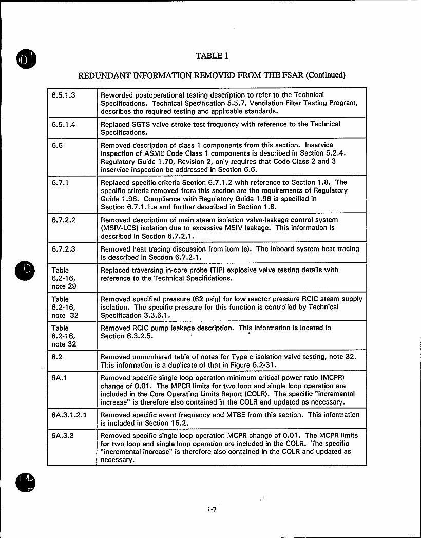
REDUNDANTINFORMATIONREMOVED FROM THE FSAR (Continued)
6.5.1.3
6.5.1 A
6.6
6.7.1
6.7.2.2
6.7.2.3
Table6.2-16,note 29
Table6.2-16,note 32
Table6.2-1 6,note 32
6.2
6A.1
6A.3.1.2.1
6A.3.3
Reworded postoperational testing description to refer to the TechnicalSpecifications. Technical Specification 5.5.7, Ventilation Filter Testing Program,describes the required testing and applicable standards.
Replaced SGTS valve stroke test frequency with reference to the TechnicalSpecifications.
Removed description of class 1 components from this section. Inserviceinspection of ASME Code Class 1 components is described in Section 5.2.4.Regulatory Guide 1.70, Revision 2, only requires that Code Class 2 and 3inservice inspection be addressed in Section 6.6.
Replaced specific criteria Section 6.7.1.2 with reference to Section 1.8. Thespecific criteria removed from this section are the requirements of RegulatoryGuide 1.96. Compliance with Regulatory Guide 1.96 is specified inSection 6.7.1.1.e and further described in Section 1.8.
Removed description of main steam isolation valve-leakage control system(MSIV-LCS) isolation due to excessive MSIV leakage. This information isdescribed in Section 6.7.2.1.
Removed heat tracing discussion from item (e). The inboard system heat tracingis described in Section 6.7.2.1.
Replaced traversing in-core probe (TIP) explosive valve testing details withreference to the Technical Specifications.
Removed specified pressure (62 psig) for low reactor pressure RCIC steam supplyisolation. The specific pressure for this function is controlled by TechnicalSpecification 3.3.6.1.
Removed RCIC pump leakage description. This information is located inSection 6.3.2.5.
Removed unnumbered table of notes for Type c isolation valve testing, note 32.This information is a duplicate of that in Figure 6.2-31.
Removed specific single loop operation minimum critical power ratio (MCPR)change of 0.01. The MPCR limits for two loop and single loop operation areincluded in the Core Operating Limits Report (COLR). The specific "incrementalincrease" is therefore also contained in the COLR and updated as necessary.
Removed specific event frequency and MTBE from this section. This informationis included in Section 15.2.
Removed specific single loop operation MCPR change of 0.01. The MCPR limitsfor two loop and single loop operation are included in the COLR. The specific"incremental increase" is therefore also contained in the COLR and updated asnecessary.
1-7

iy, ~
I~
Iy
l'.I
k~i
t.'ye'
~ y'I

TABLE I
REDUNDANTINFORMATIONREMOVED FROM THE FSAR (Continued)
6A Removed Table 6A.3-6. The SLMCPR at SLO is included in the COLR and isupdated for each operating cycle. Current CPR values are included in text. Theoriginal CPR values are obsolete and are not required to support the description inthis section.
Chapter 7
Section
7.1.2.1
7.1.2.2
7.2.1.1.1 0
7.2.'1.2.5
7.2.2.2
7.3.2.1.2
7.4.1.4.2
7.4.2.2
7.5.2.2.3
7.6.1.7
7.7.1.1 5
7.7.1.2.2
7.7.1.2.2.2
Description of Change
Replaced list of general regulatory requirements with reference to the applicabledescriptions in Sections 7.1 through 7.6 for degree of conformance.
Replaced description of compliance with General Design Criteria (GDC) 1, 2, 3, 4,10, 13, 54, 55, and 56 with reference to Section 3.1.
Removed RPS power supply discussion from this section. This information islocated in Section 7.2.1.1.
Removed description of the RPS power supply details. This information isprovided in Section 8.3.1.1.6.
Removed discussion on qualification testing and preoperational testing for relaypanels. This information is provided in Section 3.10 and Chapter 14.
Removed discussion on qualification testing and preoperational testing for relaypanels and the reactor protection system (RPS). This information is provided inSection 3.10 and Chapter 14.
Replaced listing of specific remote shutdown system (RSS) controls andindicators with reference to the Licensee Controlled Specifications (LCS).LCS 1.3.3.2 provides the same information.
Removed specific information on qualification tests of relay panels and in-situpreoperational testing of these sensors, channels, and the entire protectionsystem. This information is provided in Sections 3.10, 3.11, and 14.2.
Removed SRV position monitoring discussion. This information is included inSection 7.5 ~ 1.9.
Removed the suppression pool high temperature specific values. The monitoredoutputs (90, 105, 110, and 120') are controlled by the Technical Specifications.
Removed reference to Appendix B, item III.A.1.2 for transient data acquisitionsystem (TDAS) inputs provided to the emergency response data system (ERDS).This information is addressed in the Emergency Plan.
Removed control rod drive (CRD) mechanical operation description. Thisinformation is included in Section 4.6.1.1.2.
Removed discussion regarding reactor manual control system (RMCS)inputs/signals. This information is located in Section 7.7.1.8.
1-8

N 1[
'r~
"c4E g%FQ
I~V"
0

TABLEI
REDUNDAbKINFORMATIONREMOVED FROM THE FSAR (Continued)
7.7.1.2.2.4
Table 7.3-14
Removed details of RMCS operation. This information is located inSection 7.7.1.2.2.
Removed footnotes to Table 7.3-14. This information is described inSection 7.3.1.1.11.
Section
8.1
8.1.3
8.1.3
8.1.5.2
Figure 8.1-7
8.3.1 ~ 1.1
8.3.1.1.6
Table 8.3-23
~Fi ures8.3-18.3-28.3-238.3-32
Chapter 8
Description of Change
Removed Tables 8.1-1, 8.1-2, and 8.1-3 (Division 1, 2, and 3 loads). Therequired information is provided in Tables 8.3-1, 8.3-2, and 8.3-3.
Removed description of offsite power source and backup offsite power sourcefrom this section. Offsite power source information is included in Section 8.1.2.
Removed description of 4.16-kV Class 1E bus being normally fed by thenon-Class 1E switchgear from this section. This information is provided inSection 8.1.2.
Removed RPS motor generator (MG) set voltage regulation details from thissection. This information is provided in Section 8.3.1.1.6.
Replaced Figure 8.17 with a reference to Figures 1.2-1 and 1.2-4.
Removed frequency for loss of offsite power testing of the diesel generators.The frequency for the loss of offsite power test is located in TechnicalSpecification SR 3.8.1.11.
Removed specific environmental and seismic details for EPA assemblies. Theseismic and environmental qualification of components is described in Sections3.10 and 3.11 along with the QID files which are referenced in Section 3.11.
Removed Table 8.3-23. The information in Table 8.3-23 is redundant to thatcontained in Figure 8.1-2.
Removed degraded and loss of voltage setpoints from the figures. The voltagesensing setpoints are described in the text in Section 8.3.1.2.4.3.
Chapter 9
Section
9.1.2
9.1.2.3.2
Description of Change
Replaced specific spent fuel pool water supply and makeupdiscussions/references with reference to Section 9.1.3.
Removed details on fuel handling accident analysis that are described inSection 15.7.4.
1-9
~ 4

TABLE 1
REDUNDANTINFORMATIONREMOVED FROM THE FSAR (Continued)
9.1.2.3.6.2
9.1.3.4
9.1.4.2.1 0.2
Table 9.1-3
Table 9.1-9
9.2.1.4
9.2.5.1
9.2.5.2
9.2.5.3
9.2.5.3
9.2.5.3
9.2.5.4
9.2.6.2
9.2.7.2
9.2.7.5
9.3.1.2.1
9.3.1.2.2
Replaced details from discussion of fuel handling accidents with reference toChapter 15.
Removed system operating details from this section. This information is includedin Section 9.1.3.2.
Removed general purpose grapple description from this section. This informationis included in Section 9.1.4.1.
Removed fuel pool cooling and cleanup (FPC) piping and valve design temperaturefrom Table 9.1-3. The FPC system design temperature is included in Table 9.1-5.
Removed safety factor and proof testing from note (e) ~ This information isprovided in Sections 9.1.4.3 and 9.1.4.4.1.
Removed Regulatory Guide 1.37 compliance statement. Regulatory Guide 1.37compliance is addressed in Section 1.8.
Replaced Regulatory Guide 1.27 compliance statement with reference toSection 1.8.
Removed specific high-pressure core spray (HPCS) service water flow rate fromthis section. This information is included in Table 9.2-5.
Removed Figure 9.2-7b and the suppression pool transient discussion from thissection. The suppression pool temperature transient analysis is described inSection 6.2.1.
Removed specific spray pond volumes from mass loss discussion. The spraypond mass values are included in Table 9.2-3.
Removed reference to Figures 9.2-7c, 9.2-7d, and 9.2-7e and removed figures.The information in these figures (graphs) is identical to the information inTables 9.2-8 and 9.2-9.
Replaced description of preoperational test program and one time drift loss testwith a general statement on Technical Specifications required functional testingto ensure spray pond availability. The drift loss test results are retained inSection 9.2.5.3 and Figure 9.2-8.
Removed environmental qualification information for condensate pumps from thissection. This information is addressed in Section 3.11.
Removed general design requirements for SW from this section. General designcriteria requirements are described in Section 3.1.
Replaced reference to Section 1.5 with a description of the current/final GenericLetter 89-13 resolution and commitments.
Removed discussion on air-operated isolation valve actuation at 80 psig. Thisinformation is provided in Section 9.3.1.5.1.
Removed ADS accumulator backup compressed gas system pressure alarmchannel functional test and calibration requirements from this section. Thisinformation is provided in Section 9.3.1.4.
1-10

>+A
f I,
l
I /I
I
V~

TABLE 1
REDUNDANTINFORMATIONREMOVED FROM THE FSAR (Continued)
9.3.1.2.2
9.3.1.2.2
9.3.2.2
9.3.2.2.4
9.3.2.2.5
9.3.3.2.2.1
9.3.3.2.2.1
9.3.3.3
9.3.5.3
9.3.5.3
9.4.1.2.1
9.4.1.2.1
9.4.1.2.2
9.4.1.2.3
9.4.1.3.1
9.4.1.4
9.4.1.5.3
9.4.2.1
9.4.2.2.1
Replaced minimum nitrogen cylinder pressure with reference to the TechnicalSpecifications.
Moved nitrogen bottle capacity test discussion to Section 9.3.1.4.
Removed design code information from this section. Code requirements arelocated in Section 3.2.
Removed radiation protection discussion from this section. Routing and shieldingdue to radiation concerns is discussed in Section 12.3.
Removed specific hood air flow velocity from this section. The air flow velocityis discussed in Section 9.3.2.3.
Removed discussion on pipe break/flooding analysis from this section. Thisinformation is provided in Section 3.6.
Removed ECCS passive failure description. Passive failures in the ECCS systemare described in Section 6.3.
Replaced discussion on available time to identify and isolate leakage from thissection with reference to Section 6.3.
Removed time interval (18 month) from the SLC injection test description. Thetime interval for the subject injection test is included in and controlled by theTechnical Specifications.
Replaced regulatory guide compliance discussion with reference to Section 1.8.
Removed specific exhaust fan flow capacity, air handling unit heater size, and airhandling system capacity from text. This information is provided in Figure 9.4-1and Table 9.4-1.
Replaced Regulatory Guide 1.52 compliance description with reference toSection 1.8.
Removed cable spreading room heating, ventilating, and air conditioning (HVAC)heater capacity and unit flow capacity. This information is provided inFigure 9.4-1.
Removed critical switchgear area unit flow capacities from this section. Thisinformation is provided on Table 9.4-1.
Removed description of control room fire protection equipment from this section.This information is provided in Section 9.5.
Replaced filter testing details with reference to the Technical Specifications.
Replaced temperature controller setpoint discussion with reference toTable 3.11-1 for temperatures that are normally maintained.
Replaced description of temperature limits in items (a) and (d) with reference toTable 3.11-1.
Removed discussion of reactor building isolation signals from this section. Thisinformation is provided in Section 9 4.2.3.b.
1-11

4
V ~g ~
t t4C
tl
all

TABLE 1
REDUNDANTINFORMATIONREMOVED FROM THE FSAR (Continued)
9.4.2.2.1
9.4.2.2.1
9.4.2.2.2
9.4.2.2.2
9.4.2.2.2
9.4.2.2.3
9.4.2.3
9.4.2.3
9.4.3.1
9.4.3.1
9.4.3.2
9.4.6.1
9.4.6.2.1
9.4.6.2.2
9.4.6.2.5
9.4.7.1
9.4.9.2
9.4.1 0.1
Replaced reference to specific temperatures in the supply air description withreference to Table 3.11-1.
Removed specific fan capacity from 9.4.2.2.1.d. This information is provided inTable 9.4-2.
Removed description of purge to the reactor building from this section. Thisinformation is described elsewhere in this section (see Sections 9.4.2.5.e,9.4.2.5.d, and 9.4.2.3).
Removed discussion of Section 15.7 accident analysis. This information isprovided in Section 15.7.
Removed specifics on the standby gas treatment system (SGTS) functionalrequirements. This information is provided in Section 6.5.1.
Removed specific sump vent exhaust fan capacity. This information is providedin Table 9.4-2.
Removed Section 15.7 accident analysis discussion details in item (d) ~ Thisinformation is provided in Section 15.7A.2.1.
Removed ASME class and seismic class discussion from this section. Thisinformation is provided in Section 9.4.2.1.
Replaced general temperature limits with reference to Table 3.11-1.
Replaced specific minimum winter temperature (65') in item (d) with reference toTable 3.11-1 ~
Removed specific supply and exhaust air handling unit capacities. The specificcapacities are provided in Table 9.4-3.
Replaced turbine building temperature requirements with reference toTable 3.11-1.
Removed specific turbine building ventilation flow rates. This information isprovided in Table 9.4-4.
Removed specific boiler room ventilation flow rates and specific capacity of thefans provided for the transformer vaults. The boiler room flow rates are shown inFigure 9.4-6 (M546). The transformer vault fan capacities are provided inTable 9.4-4.
Removed turbine building sample room HVAC ventilation flow rates and fancapacity. This information is provided in Figure 9.4-6 and Table 9.4-4.
Removed description of the HVAC power source. This information is provided inSection 9.4.7.3.
Removed pump room HVAC actuation description from this section. Thisinformation is provided in Section 9.4.9.3.
Replaced specific SW pump house temperature limits with reference to Table3.1 1-1.
1-12

«I'

TABLEI
REDUNDANTINFORMATIONREMOVED FROM THE FSAR (Continued)
9.4.1 0.1
9.4.11.1
9.4.11.2
9.4.1 2.2
9.4.1 2.2
9A.13.1
9.4.13.2
9.4.14.1
9A.15.2
9.4.1 5.2
9.4.1 6.2
9A.1 6.3
9.5.2.2.2
9.5.3.2.2
9.5.4.4
9.5.5.2
9.5.9.1
Removed specific fan coil unit flow rates. The specific flow rates are provided inTable 9.4-6.
Replaced specific temperature limits with reference to Table 3.11-1.
Removed specific fan capacities. This information is provided in Table 9.4-2.
Removed specific flow rates and heater capacity. The specific values are shownin Figure 9.4-7 (M551).
Removed heater thermostat setting and temperature switch setpoint (50'). Theminimum temperature of 50's provided in Section 9.4.12.1.
Removed discussion on potential radioactive contaminants and safety-relatedequipment in the service building from this section. This information is providedin Section 9.4.13.3.
Removed specific fan capacity and air flow rates. The fan capacities andminimum outside air flow rates are shown in Table 9.4-8 and Figure 9.4-9respectively.
Removed discussion of potential tritium contamination from this section. Thisinformation was revised to refer to Section 9A.16.3 for the details and is locatedin the safety evaluation section (9.4.14.3).
Removed specific heater output and thermostat setpoint. The heater capacity isprovided in Figure 9.4-7. The thermostat is set to maintain the minimumtemperature specified in Section 9.4.15.1, item (b).
Removed specific heater/cooler capacities, fan capacities, and ventilation flowrates. This information is provided in Figure 9.4-7 and/or Table 9.4-9.
Removed tritium contamination discussion from this section. This information isprovided in Section 9.4.16.3.
Removed discussion on pipe break analysis from this section. This information isprovided in Section 3.6.
Removed description of communication provisions for high noise areas from thissection. High noise area provisions are provided in Section 9.5.2.4.3.
Removed diesel generator seismic category description from this section. Thediesel generator seismic classification is provided in Section 8.3.
Replaced fuel oil testing description with reference to the Technical SpecificationSection 5.5.9.
Replaced tabular information with new Table 9.5-4.
Removed emergency eyewash station description from this section. Theemergency eyewash and shower station is described in Section 9.5.9.2.
1-13

4
~q
A T, y

TABLE 1
REDUNDANTINFORMATIONREMOVED FROM THE FSAR (Continued)
Chapter 10
Section
10.2.2
1 0.2.2
1 0.2.2
10.2.3
10.2.4
1 0.2.5
10.3.2
1 0.3.2
10.3.6
10.4.1.1
1 0.4.2.3
1 0.4.3.3
10.4.4.3
1 0.4.4.4
10.4.6
10.4.6.1
Description of Change
Removed description of bulk hydrogen storage facility and associated fireprotection features. This information is provided in Appendix F.
Removed turbine digital electrohydraulic control system details from this section.Turbine control system details are provided in Section 7.7.1.5.
Replaced turbine valve testing and inspection frequencies with reference to theLCS. The testing and inspections are performed in accordance with LCSSR 1.3.7.6.1 and 1.3.7.6.3 respectively.
Removed Reference 10.2-1 and text referral in this section. This reference isincluded in the references in Section 3.5.4.
Removed transient analysis discussion from this section. Chapter 15 containsthe abnormal transient analyses.
Removed instrumentation description. This information is provided inSection 7.7.1.5.
Removed containment leakage information from this section. Containmentleakage is discussed in Section 6.2.
Removed discussion on main steam line instrumentation from this section. Mainsteam line instrumentation is described in Section 7.7 and is shown inFigure 10.3-1.
Replaced details on regulatory guide conformance with reference to Section 1.8.
Removed details on the filter demineralizer operation from this section. Filterdemineralizer operation is described in Section 10.4.6.3.
Removed description of main condenser nuclide content from this section. Thisinformation is provided in Section 11.3.2.1.
Removed system description information from this section. This information isprovided in Sections 10.4.3.1 and 10.4.3.2.
Removed turbine overspeed fail safe description from this section. Thisinformation is provided in Section 10.2.2. Also removed discussion of steam linebreak effects. This information is provided in Section 3.6.1.
Replaced turbine bypass valve test frequency with reference to the TechnicalSpecifications.
Replaced original water chemistry limits and controls description with a
description of the EPRI BWR Water Chemistry guidelines that have been adoptedat WNP-2 (EPRI TR-103515, 1996).
Removed details on Regulatory Guide 1.56 compliance from this section.Regulatory Guide 1.56 compliance is addressed in Section 1.8 and reference toSection 1.8 is located in Section 10A.6.3.
1-14

)',C.I'
~ii
sJ,>„A
'P
1 a,

TABLE I
REDUNDANTINFORMATIONREMOVED FROM THE FSAR (Continued)
10.4.6.5
10A.6.5
1 0.4.6.6
1 0.4.7.2.1
Removed filter demineralizer hold pump and resin trap description from thissection. This information is provided in Section 10.4.6.2.
Removed filter demineralizer service system descriptions. This information isprovided in Section 10.4.6.2.
Removed discussion on Regulatory Guide 1.56 compliance from this section.This information is provided in Section 1.8.
Removed instrumentation description Section 10.4.7.2.1. This information isprovided in Section 10.4.7.5.
Chapter 11
Section
11.2.1
11.2.2.6
11.3.1
1 1 .3.2.4.5
1 1.3.2.6.4
11 A.2
1 1.4.2A
11 A.2.7
11A.2.11
1 1.5.2.1.4
Description of Change
Removed Regulatory Guide 1.143 compliance statement. Regulatory guidecompliance is described in Section 1.8.
Removed description of radwaste building seismic category and tank failureanalysis. This information is provided in Sections 3.8.4.1.2 and 11.2.1respectively.
Replaced GDC 60 and 64 compliance discussion with a reference to Section 3.1 ~
Also removed description of buildings containing radioactive gas sources that isredundant to Section 11.3.2.2.
Replaced steam jet air ejector (SJAE) sample frequency with reference to theTechnical Specifications.
Removed description of offgas and effluent release radiation monitor testing.This information is not pertinent to "charcoal performance." Section 11.5.2.3.4describes process and effluent radiation monitor inspection, calibration, andtesting.
Removed Regulatory Guide 1 ~ 143 compliance statement. Regulatory guidecompliance is described in Section
1.8.'emoved
location of waste sludge separator tank from this section. Section11.4.2.1 states that the solid waste processing areas are located in the radwastebuilding.
Replaced specific design basis offgas release rate with reference to Section11.3.1.
Removed discussion of compliance with NRC and Department of Transportation(DOT) regulations. Section 11.4.2.9 discusses compliance with NRC and DOTregulations for packaging and shipment.
Removed description of two 100% RHR heat exchangers from this section. Thedescription of two redundant RHR loops and heat exchangers is provided inSection 5.4.7.
1-15

;1,f, tP
a~k$'j
gE

TABLE I
REDUNDANTINFORMATIONREMOVED FROM THE FSAR (Continued)
1 1.5.2.2.2.1
1 1.5.2.2.3
Replaced SW radiation monitor description in this section with reference toSection 11.5.2.1.4.
Removed elevated release duct radiation monitoring system description from thisSection. This system is described in Section 11.5.2.2.1.5.
Chapter 12
Section
12.3.1.2
12.3.4.3
1 2.5.2.2
Description of Change
Removed description of plant layout and radiation zones from this section. Thisinformation is provided in Section 12.3.1.1.
Removed the criticality alarm for the new fuel vault detectors and providedreference to the LCS.
Removed text describing radiation sources within instrument calibrationlaboratory and added reference to Table 12.2-12, which provides the location andquantity of all radiation sources.
Section
1 3.2.2.3
13A.1
13.5.1.2
Chapter 13
Description of Change
Removed qualifications of Shift Technical Advisor (STA) from Section 13.2.2.3.This information is provided in Section 13.1.3.2.4.
Replaced description of Plant Operations Committee (POC) activities withreference to the Operational Quality Assurance Program Description (OQAPD).The content of the OQAPD is controlled by 10 CFR 50.54(a).
Replaced POC description of POC review of safety related procedures withreference to the OQAPD. The content of the OQAPD is controlled by10 CFR 60.64(a).
Chapter 14
ISection
1 4.2.1 2.3.9
Description of Change
Removed test 16B from Section 14.2.12.3.9. This test was moved toSection 14.2.12.3.16.2 to follow test 16A.
Section
1 5.1.2
1 6.1.4
Chapter 15
Description of Change
Removed analysis details that are included in Tables 15.1-1 and 15.0-1.
Replaced analysis input specifics with reference to Table 15.0-2.
1-16

k
~~
~ t„I ~
It
„It„'I4ttt tt
t t
I
%a Ittt-'t

TABLE 1
REDUNDANTINFORMATIONREMOVED FROM THE FSAR (Continued)
1 5.4.7.3.2
Figures15.4-1 to1 6.4-5
Figure1 5.4-9
Removed reference,to Figure 15.4-9. This figure is being removed from theFSAR and is provided in the cycle specific reload report.
Removed Figures 15.4-1 through 15.4-5 related to control rod reactivity from theFSAR. These figures are provided in the cycle-specific reload report.
Removed Figure 15.4-9 (base rod pattern and misplaced bundle locations) fromthe FSAR. This figure is provided in the cycle-specific reload report.
Appendix B
Item
I.A.1.1
I.A.1.3
I.A.2.1
I.A.2.3
I.A.3.1
I.B.1.2
I.C.3
I.C.5
I.D.2
II.B.2
II.B.4
II.D.1
II.D.3
II.E.4.1
II.E.4.2
II~ F.1.1
II.F.1.2
II.K.1.10
II.K.3.1 3
II.K.3.1 5
II.K.3.16
II.K.3.1 7
Description of Change
Removed item is addressed in Sections 13.1.2.2.4, 13.2.2.3.1, and 13.1.2.3.4.
Removed item is addressed in Section 13.1.2 and Technical Specifications 5.2.
Removed item is addressed in Section 13.2.2.
Removed item is addressed in Section 13.2.2.
Removed item is addressed in Section 13.2.2.
Removed item is addressed in the OQAPD.
Removed item is redundant to the item I.A.1.2 response.
Removed item is addressed in the OQAPD.
Removed item is addressed in Sections 7.5.1.2 and 7.7.1.1.5.
Removed item is addressed in Appendix J.
Removed item is addressed in Section 13.2.
Removed item is addressed in Section 5.2.2.10.
Removed item is addressed in Section 7.5.1.9 and Table 7.6-1.
Removed item is addressed in Section 6.2.5.
Removed item is addressed in Section 6.2.4
Removed item is addressed in Section 11.5.
Removed item is addressed in Section 11.5.
Removed item is redundant to items II.K.1.5 and I.C.6.
Removed item is addressed in Sections 5.4.6, 5.4.6.3, and 7.4.1 ~ 1.
Removed item is addressed in Sections 5 4.6, 5.2.5,'7.5, and 7.6.1.3.
Removed item is addressed in Section 5.2.2.10.
Removed item is related to obsolete information.
1-17

D
1" >I ft I
lpga
,," C<.
N
l
I 4
T
V

TABLE 1
REDUNDANTINFORMATIONREMOVED FROM THE FSAR (Continued)
II.K.3.18
II.K.3.22
II.K.3.24
II.K.3.27
II.K.3.28
II.K.3.3
II.K.3.30
II.K.3.31
III.A.1.1
III.A.1.2
III.D.1 ~ 1
III.D.3.4
Removed item is addressed in Section 7.3.1.
Removed item is addressed in Sections 5.4.6, 7A, and 7.3.
Removed item is addressed in Section 9.4.9.
Removed item is addressed in Sections 7.5 and 7.7.
Removed item is addressed in Section 9.3 and Technical Specifications 3.5.1.
Removed item is addressed in the Technical Specifications 5.6.4.
Removed item is addressed in Section 6.3.
Removed item is redundant to item II.K.3.30.
Removed item is addressed in the Emergency Plan.
Removed item is addressed in the Emergency Plan.
Removed item is addressed in the Technical Specification 5.5.2.
Removed item is addressed in Section 6.4.
1-18

«' x
~M

TABLE2
DELETED INFORMATION
Chapter 1
No deleted information.Chapter 2
Section
2.2.1
2.3.1.2
2.3.2.2
Description of Change
Deleted mileages stated for variousroad types and deleted railroad mileageand commercial rail names.
Deleted precipitation intensitydefinitions and referred to the citedReference 2.3-5.
Deleted detailed description of theHanford Meteorological Station (HMS)and added statement, "The HanfordReservation maintains a network ofmeteorological towers, which can beaccessed for data by telephone orelectronic form."
Basis for Change
Specific milages and commercial railnames have no impact on the facility andare considered excessive detail.
The information being deleted is containedin the specified reference. Thisinformation is considered to be excessivedetail for inclusion in the FSAR.
The information being deleted does notdescribe the WNP-2 facility or any processand is not associated with any aspect ofthe WNP-2 facility or processes and is notrequired to support any discussions in theFSAR related to WNP-2.
Chapter 3
Section
3.5.1.3
3.5.1.4
Description of Change
Deleted description of turbine rotormissile generation probability related tothe original "shrunk-on-disc type LProtors."
Deleted Table 3.5-5.
Basis for Change
The rotors were replaced in 1992,obviating any reason to retain thehistorical information related to the originalrotors.. The information being deleted isobsolete.
The information listed in Table 3.5-5 isbased on the original design basis tornadoinformation that is no longer applicable toWNP-2. Any changes or new constructionwould have to be evaluated based on thecurrent design basis tornado. Theinformation being deleted is obsolete.
Chapter 4
Section
4.1.5
Description of Change
Deleted historical references to pastreload reports which are no longerapplicable to WNP-2.
Basis for Change
This information is obsolete.
2-1

/
le

TABLE2
DELETED INFORMATION(Continued)
4.2.5
4.3.5
4.5.1.5
Deleted historical references to pastreload reports which are no longerapplicable to WNP-2.
Deleted historical references to pastreload reports which are no longerapplicable to WNP-2.
Deleted statement requiring a GEService Department representative tobe present during inspection of controlrod drive (CRD) components instorage.
This information is obsolete.
This information is obsolete.
The requirement was a GE requirementapplicable during the initial receipt andstorage of the components and no longerapplies to long-term storage ofreplacement parts. This information isobsolete.
Chapter 5
Section
5.2.1
5.2.2.4.1
5.2.2.6
5.2.3.2.2
Description of Change
Deleted Tables 5.2-13 and 5.2-14,ASME Section III, 1971 summer andwinter addenda changes.
Deleted discussion as to why thesafety/relief valves (SRVs) are locatedon the main steam lines and not thevessel top head.
(1) Deleted specific code edition andadded applicable subsection.(2) Deleted statement on NRC adoptingASME Codes.
Deleted evaluation and testinginformation used to support originalwater chemistry limits.
Basis for Change
The ASME Section III 1971 Summer and1971 Winter addenda changes wereadequately reviewed and determined toimpose no new technical requirements orchanges in quality control procedures fromthe code version applied. This informationis an historical statement of fact that isnot subject to change and is consideredexcessive detail for the current FSAR.
This information is not pertinent to thedesign or operation of the SRVs and is notnecessary to support the rest of thediscussion. This information is thereforeexcessive detail.
(1) Deleting the specific code edition doesnot change the intent to comply with thespecified code in effect at the time.(2) This statement of fact is not pertinentto the description of the design oroperation. The information being deletedis excessive detail.
Current water chemistry controls andlimits have been established based onextensive study, experience, and testingthat essentially supersede the originalinformation being deleted.
2-2

r,k
0

TABLE2
DELETED INFORMATION(Continued)
Deleted reference to Table 5.2-6,Reactor Water Parametric Values, anddeleted Table 5.2-6.
Deleted information on oxygengeneration and content.
Deleted details concerning preserviceinspection program submittals.
Deleted details related to examinationtechniques and qualifying procedures.
Deleted feasibility of inspectionmethodology discussions.
Deleted information on source ofmockup nozzle.
Deleted "hydrolaser" as the specificdecontamination method that wouldhave to be performed to access thefeedwater nozzles.
Deleted instrument ranges as shown.
Information on this table is not required tosupport the new water chemistrydiscussion and is obsolete.
The details on plant conditions andphenomena that result in various oxygenconcentrations in the reactor coolant arenot subject to change. The result orconclusion to this discussion is maintainedin the FSAR as a maximum expectedconcentration of 8 ppm. The informationbeing deleted is excessive detail.
The information concerning the preserviceinspection program submittals is historical,administrative information that is notsubject to change and does not relate tothe design or operation of the facility.This information is excessive detail.
Deleted information is excessive detailwhich is inherent to code compliancewhich is committed to in Section 5.2.4.3.
Information on the feasibility ofexamination methods that are notemployed is excessive detail.
This information is excessive detail.
The specific type of decontamination hasno bearing on the need to decontaminateas part of the justification for notperforming feedwater nozzle internalinspections and is considered excessivedetail.
Operator use of the listed instruments forthe detection of unidentified leakage isbased on unexplained changes in theindications not on specific values.Specifying the instrument ranges in thissection is not required to support thesafety design basis of the function(unidentified leakage detection). Thisinformation is therefore excessive detail.
2-3

l
I~
4 R
h
g

TABLE2
DELETED INFORMATION(Continued)
5.2.5.5.3
5.3.3.1.4.4
5.4.1.3.1
5.4.6.2.1.1
5.4.6.2.1.1
5.4.6.2.2.2
5.4.6.2.2.2
Deleted critical crack size analysisdetails.
Deleted reactor vessel insulation heattransfer information.
Deleted discussions on the effects oflow net positive suction head (NPSH)on various components and generalNPSH discussion.
Deleted details associated with theresidual heat removal (RHR) NPSHanalysis.
Deleted reactor core isolation cooling(RCIC) exhaust valve numbers.
Deleted specific value for highestelevation in the RCIC system.
Deleted RHR steam supply valvedescnption.
The details of the analytical evaluation ofthe physical phenomena that was used tosupport the adequacy of leakage limits isnot subject to change and is contained inthe referenced document. Thisinformation is therefore consideredexcessive detail.
The specific heat transfer rate of thereactor insulation at normal operatingconditions is not pertinent to thedescription of the vessel integrity and isconsidered excessive detail.
The descriptions of physical phenomenaassociated with low NPSH and thepossible effects on various equipment arenot subject to change and are not requiredto support the overall design and functionrequirements that limit cavitation toprevent damage. This information istherefore excessive detail.
The bounding results that are retainedadequately define the safety design basis.The information being deleted is notimportant in providing an understanding ofthe analysis methodology. Thisinformation is excessive detail.
The specific valve numbers are excessivedetail for the context of the discussion.
Removing the specific value does not alterthe description of the function of theorifice to maintain a "positive pressure inthe RCIC system at the highest elevation."The specific value is therefore excessivedetail.
The RHR steam condensing mode hasbeen deactivated. Steam supply to RHR isnot part of the current plant design. Thisinformation is obsolete.

V
VVIII bV
VII
I 'I ~
II
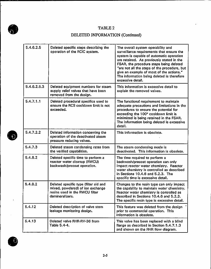
TABLE2
DELETED INFORMATION(Continued)
5.4.6.2.5
5.4.6.2.5.3
5.4.7.1.1
5.4.7.2.2
5.4.7.3
5.4.8.2
5.4.8.2
5.4.12
5.4.1 3
Deleted specific steps describing theoperation of the RCIC system.
Deleted equipment numbers for steamsupply relief valves that have beenremoved from the design.
Deleted procedural specifics used toensure the RCS cooldown limit is notexceeded.
Deleted information concerning theoperation of the deactivated steampressure reducing valves.
Deleted steam condensing rates fromthe verified capabilities.
Deleted specific time to perform areactor water cleanup (RWCU)backwash/precoat operation.
Deleted specific type (filter aid andmixed, powdered) of ion exchangeresins used in the RWCU filterdemineralizers.
Deleted description of valve stemleakage monitoring design.
Deleted valve RHR-RV-36 fromTable 5.4-4.
The overall system operability andsurveillance requirements that ensure thesystem is capable of automatic operationare retained. As previously stated in theFSAR, the procedure steps being deleted"are not all the steps of the procedure, butgive an example of most of the actions."The information being deleted is thereforeexcessive detail.
This information is excessive detail toexplain the removed valves.
The functional requirement to maintainadequate precautions and limitations in theprocedures to ensure the potential forexceeding the 100'ooldown limit isminimized is being retained in the FSAR.The information being deleted is excessivedetail.
This information is obsolete.
The steam condensing mode isdeactivated. This information is obsolete.
The time required to perform abackwash/precoat operation can onlyimpact reactor water chemistry. Reactorwater chemistry is controlled as describedin Sections 10.4.6 and 5.2.3. Thespecific time is excessive detail.
Changes to the resin type can only impactthe capability to maintain water chemistry.Reactor water chemistry is controlled asdescribed in Sections 10.4.6 and 5.2.3.The specific resin type is excessive detail.
This feature was deleted from the designprior to commercial operation. Thisinformation is obsolete.
This valve has been replaced with a blindflange as described in Section 5.4.7.1.3and shown on the RHR flow diagram.
2-5

I
~ r"
th
pf

TABLE2
DELETED INFORMATION(Continued)
Chapter 6
Section
6.1.2
6.2.5.1
6.4.4.2.1
6.4.4.2.2
6.4.5
6.7.2.3
6A.3.1.2.2
Description of Change
Deleted control lines for therecirculation system flow controlvalves (FCVs) as a source of organicmaterial in containment.
Revised item (c) to reflect thathydrogen generation from organic paintwas not considered in the hydrogengeneration analysis and deletedFigures 6.2-21 and 6.2-23 related toorganic paint hydrogen generation.
Deleted discussion of WNP-1 chlorinesources.
Deleted postulated tornado as theinitiator of sodium release and ignitionaccident at the Fast Flux Test Facility(FFTF).
Deleted specific date for RegulatoryGuide 1.52 used for control roomheating, ventilating, and airconditioning (HVAC) testing.
Deleted approximate valve travel speedof 12 in./minute from the motor-operated valve (MOV) description initem (b).
Deleted description of the recirculationpump overspeeding with the turbine.
Basis for Change
The FCV control lines have been removedas part of the adjustable speed drive (ASD)modification. This information is obsolete.
WNP-2 is an oxygen control plant.Hydrogen generation due to organic paintsis conservatively not considered. Theinformation related to hydrogen generationfrom organic paints does not apply to thisfacility.
WNP-1 has been abandoned and does nothave the described chlorine sources onsite.This information is obsolete.
The identification of a tornado as theinitiating event is not required for theWNP-2 habitability analysis and isexcessive detail.
Current testing is performed in accordancewith Regulatory Guide 1.52, Revision 2,per the Technical Specifications.Predelivery and postdelivery were mostlikely performed in accordance with therevision in effect at the time. Thespecified date (revision) is excessive detailfor this discussion and is controlled by theTechnical Specifications.
The valve stroke time is not pertinent tothe discussions or descriptions in thissection and is not relied on to support anyaspect of the system operation. Stroketimes are periodically measured to detectdegradation per the inservice testing (IST)program. The specific stroke time isexcessive detail for this section.
The recirculation pumps will no longeroverspeed with the turbine following theASD modification. This information isobsolete.
6A.4 Deleted description of maintaining therecirculation flow controller in manual.
This information is not applicable to theASD recirculation pump controls and isobsolete.

hh
vr
"lhllW
h

TABLE2
DELETED INFORMATION(Continued)
Chapter 7
Section
7.2.1.1.1
7.2.1.1.4
7.2.1.1.9
7.2.2.2
7.2.2.3
7.3.1.1.2
Description of Change
Deleted reference to TechnicalSpecifications 3.10.5 and 3.10.6 forshorting link surveillance exceptions.
Deleted specific type of turbine throttlevalve stem position switch for reactorprotection sytstem (RPS) input (double-pole/single throw).
Deleted reference to Figure 7.2-8,Process Radiation Monitor IED.
Deleted gross fuel failure detectionfrom RPS inputs.
Deleted MSLRM testing description.
Deleted specific valve type (solenoidoperated) for the RHR sample linecontainment isolation valves.
Basis for Change
These surveillance exceptions applied toinitial startup and training and weredeleted during Improved TechnicalSpecifications (ITS) implementation. Theinformation being deleted is obsolete.
The specific switch type is not required tosupport the description of the valveclosure input to the RPS. The specificswitch type is excessive detail.
The main steam line radiation monitor(MSLRM) trip has been deleted from theRPS input. This figure is no longerrelevant to the RPS description and isobsolete.
The MSLRM trip has been removed fromthe design. This information is obsolete.
The MSLRM RPS input has been removedfrom the design. This information isobsolete with respect to the RPS.
The specific valve type is not required tosupport the associated discussion and isexcessive detail.
7.4.1.1.2 Deleted RHR heat exchanger steam line This valve is deactivated and lockedvalve from item (a). closed. This information is obsolete.
7.7.1.2
7.7.1.9
7.7.1.13
Deleted description of CRD controlroom temperature alarm.
Deleted various specific details relatedto the process computer operation,software, and hardware.
Deleted information related to theservice platform and hoist.
The alarm was previously deactivated(BDC 87-125-OA). This information isobsolete.
The information being deleted is notrequired to support the description of thefunctional requirements of the processcomputer and is excessive detail ~
The service platform has been removed.This information is obsolete.
2-7

t
r,II/ 1h $ . / 'I V a
)f ~Mo
~'I
I
I

TABLE2
DELETED INFORMATION(Continued)
Chapter 8
Section
8.1.1
8.1
8.3.1.2.2
8.3.2.1.7.2
Description of Change
Deleted the historical information onwhen the Bonneville PowerAdministration (BPA) was established.
Deleted Figure 8.1-3.
Deleted description of high-pressurecore spray (HPCS) diesel periodic testthat loads the diesel to 100%, dropsthe largest load, and restarts thelargest load while concurrently feedingthe rest of the bus loads.
Deleted station battery exceptions toIEEE 450 for cell to cell and terminalconnection resistance tests andperformance tests when degradedconditions exist.
Basis for Change
This level of detail is not required toestablish BPA role in WNP-2 operations.
Figure 8.1-3 is an old drawing of the BPAgrid and is inaccurate and no longercorrect. There is no longer any BPAcontrolled figure which represents thisinformation The relevant informationwhich the drawing provided, in particularshowing that the offsite lines to WNP-2are physically separated and do not sharethe same right-of-way, is incorporated intoa note on Figure 8.1-5 and in the text inSection 8.1.5.1.
The subject test was performed duringpreoperational testing as described inresponse to FSAR Appendix I issue PSB-2and Chapter 14. This information isobsolete with respect to context of thissection. Required testing is included in theTechnical Specifications.
ITS implementation resulted in changes tothe testing requirements that eliminatedthe need for these exceptions. Theinformation being deleted is obsolete.
Chapter 9
Section
9.1.4.2
Description of Change
Deleted description of fuel pool sipperand channel gauging fixture andreplaced with statement that theoriginally supplied equipment is notused. Also deleted associatedFigures 9.1-9 and 9.1-10.
Basis for Change
The equipment described is not used. Anyfuel sipping or channel gauging would beperformed by the refueling vendor usingtheir own equipment and approvedprocedures. The information being deletedis obsolete.
9.1.4.2.5.9 Deleted service platform discussion. The service platform has been removed;this information is obsolete.
2-8

lt * IP
01NA~mk 1
0
gC
4 ) I,

TABLE2
DELETED INFORMATION(Continued)
Deleted fuel sipping equipmentdescription.
Deleted service platform informationfrom vessel closure description.
Deleted potable water and sanitarydrain systems design, testing, andinstrumentation details.
Deleted condensate storage tankspecific coating repair material ~
Deleted condensate storage tank levelswitch setpoints.
(1) Deleted compressor jacket watermanufacturer and preservice testinginformation (2) Deleted compressorjacket water instrumentation details.
Deleted timer type and specific timercycle range.
The equipment described in the FSAR isnot used. Any fuel sipping would beperformed by the refueling vendor usingthere own equipment and approvedprocedures. The information being deletedis obsolete.
The service platform has been removed,this information is obsolete.
The potable water and sanitary drainsystems are of conventional design andhave no safety function. The informationbeing deleted is excessive detail notrequired to be maintained for the systemsto perform their overall design functions.
Eliminating the specific repair material doesnot alter the overall design aspectsintended to provide corrosion protectionfor the tanks. The specific material isexcessive detail.
The specific levels at which the switchesare set does not impact the overallconclusion that the reserve capacity isapproximately 67,500 gal per tank. Thesetpoints are determined by appropriatecalculations and controlled by theinstrument datasheets to ensure therequired reserve volume is maintained inthe tank. The specific setpoints areexcessive detail.
(1) Testing and inspection for anymodifications or replacements will beperformed as required by applicable codesand standards, the information beingdeleted is not pertinent to current or futureplant operation and is obsolete. (2) Thedesign information being deleted is notrequired to maintain the overall designfunction and interfaces and is excessivedetail.
The function of the compressed air systemis not dependent on the type of timer orthe dryer cycle time. The informationbeing deleted is excessive detail.
2-9

l
IIy, I
Av
c~lik w
t
'W3;v
lt
v
l'

TABLE2
DELETED INFORMATION(Continued)
Deleted nonradioactive floor drainsfrom the sources that can be pumpedto the storm drain system.
Deleted steam tunnel equipment drainsfrom reactor building drain sump list.
Deleted description of floor draindowncomer instrumentation.
Replaced standby liquid control (SLC)tank fill and solution mixing detailswith reference to the TechnicalSpecifications.
Replaced testing details with referenceto the Technical Specifications.
Deleted high chlorine level in the intakeheader from the emergency filteroperation events.
Deleted details on how the springreturn to "AUTO" control switch forthe containment purge isolation valvesworks.
Deleted reactor building HVACtemperature controller initial setpoint.
Operating practices have been changedsuch that the nonradioactive floor drainsare not normally pumped to the stormdrains. The information being deleted isobsolete.
The steam tunnel equipment drains havebeen redirected to the floor drain system.This information is obsolete.
The instrumentation has been removedfrom the design. This information isobsolete.
The specifics being deleted do not impactany design function as long as the overallrequirements, as specified in the TechnicalSpecifications, are maintained.
Testing and operability requirementscontained in the Technical Specificationsensure system availability. The testingmethodology information being deleted isnot required to maintain the overall systemdesign function and is excessive detail ~
The emergency filter operation initiation onhigh chlorine function has been eliminated.This information is obsolete.
The information being deleted is standarddesign information for the type ofvalve/control described. The overalldesign function of the valve to be able toopen/close and to fail closed on anisolation signal is being retained. Theinformation being deleted is excessivedetail.
The temperature limits listed inTable 3.11-1 are the controlling factor indetermining the specific setpoints at whichthe heating control instruments are set.The controller initial setpoint is excessivedetail.
2-10

slt l' I
I
'tpls
~ '

TABLE2
DELETED INFORMATION(Continued)
Deleted reactor building HVACevaporative cooler control andoperation details.
Deleted specific value for time delayprior to starting the standby pump.
Deleted description of operating theturbine building HVAC in recirculationmode from item (b).
Deleted description of capability topressurize the turbine building duringperiods of low contamination potentialin the turbine building.
Deleted description of operating theturbine building HVAC in recirculationmode.
Deleted description of turbine buildingsample room air conditioning unit.
Deleted turbine building HVACinstrumentation and control details.
The reactor building evaporative cooler isassociated only with the cooling functionof the reactor building normal HVACsystem. The temperature limits specifiedin Table 3.11-1 are not impacted by thischange. The specific setpoints and detailsof how the cooler works are excessivedetail.
The time delay prior to starting thestandby pump is a design feature to inhibitspurious standby pump starts. Thespecific duration of the time delay isinconsequential as long as the delay ispresent and supports the desired operationof the system. The specific value of thetime delay is excessive detail.
The system has been modified such thatthe recirculation mode is no longeravailable. This information is obsolete.
There are no periods of low contaminationpotential in the turbine building. Thisinformation is obsolete.
The system has been modified such thatthe recirculation mode is no longeravailable. This information is obsolete.
The specified design function of theturbine building sample room airconditioning unit, as described inSection 9.4.6.1, is to "provide temperedventilation air to the sample room." Theair conditioning unit is provided forpersonnel comfort and is sizedaccordingly. The air conditioning unitspecifics being deleted are excessivedetail.
The design functions of the turbinebuilding HVAC system described are notaffected by this change. The informationbeing deleted is beyond the level of detailrequired to describe operation of thesystem is excessive detail.
2-11

4 *I
I4
Wl
If
'II
I

TABLE2
DELETED INFORMATION(Continued)
9.4.11.5
9.4.13.1
9.4.13.5
9.4.14
9.4.15.2
9.4.1 6.1
9.4.1 6.2
9.4.1 6.5
9.5.2.2.4.2
Deleted details on the operation of the"ON" switch for the recirculation fans.
Deleted specific design temperature forthe service building.
Deleted service building HVAC systeminstrumentation details.
Deleted water treatment area andmachine shop HVAC design andoperation specifics and details.
Deleted specific temperature formodulation of the circulation waterpump house eductor room dampers.
Deleted specific design temperature forthe service building.
Deleted details on plant heating systemcondensate pump sets.
Deleted details on plant heating systemcontrol instrumentation.
Deleted description of emergencysignals for general evacuation andcontainment evacuation.
This information on the operation of the"ON" switch for the recirculation fans isexcessive detail.
The specific temperature for the servicebuilding has no bearing on normal oremergency operation of the plant. Theservice building temperature is maintainedfor personnel comfort. The specifictemperature is excessive detail.
The service building HVAC systeminstrumentation is only required to functionto support system operation to maintaintemperature for personnel comfort.Discussion of specific components orprocesses that are used to accomplish thisfunction is excessive detail ~
A general description of the system designfunctions and interfaces with other plantsystems is retained. The information beingdeleted is excessive detail.
The setpoint is set to support operation ofthe system to maintain temperature asspecified in Section 9.4.15.1.d. Thespecific temperature setpoint for dampermodulation is excessive detail.
The specific temperature for the servicebuilding has no bearing on normal oremergency operation of the plant. Theservice building temperature is maintainedfor personnel comfort. The specifictemperature is excessive detail.
A general description of the system designfunction and interfaces with other plantsystems is retained. The information beingdeleted is excessive detail.
A general description of the system designfunction and interfaces with other plantsystems is retained. The information beingdeleted is excessive detail ~
The dedicated signals have been replacedby an alert tone followed by anannouncement. The information beingdeleted is obsolete.
2-12

I lI
7a'g
p~q$
*r s
1 0l
V 'P
q~t
~ 1
l'

TABLE2
DELETED INFORMATION(Continued)
9.5.2.4.2
9.5.2.2.5
Table 9.5-2
Table 9.6-1
9.5.5.2
9.5.5.2
9.5.7.2
Deleted reference to the HanfordGenerating Project.
Deleted reference to specific Hanfordfacilities.
Deleted containment air compressorarea lighting from Table 9.5-2.
Deleted containment air compressorarea communications from Table 9.5-1.
Deleted discussion of additional marginfor DG 1A and 1B due to 85% engineloading when the generator is at itscontinuous rating.
Deleted specific heater size and watertemperature thermostat controlsetpoints.
Deleted specific operator actions takento resolve alarm conditions.
The Hanford Generating Project no longerexists. This information is obsolete.
The overall design function of the systemis to provide communications for allSupply System facilities in the Hanfordarea. The names of the specific facilitiesare excessive detail.
The containment air compressor has beenremoved from the design. Thisinformation is obsolete.
The containment air compressor has beenremoved from the design. Thisinformation is obsolete.
This is a qualitative observation and thereis no calculational basis for this statement.Deleting this statement does not alter thedescription of the diesel generators or theengines and does not alter any process asdescribed in the FSAR. The informationbeing deleted is excessive detail.
The heater and thermostat control watertemperature to maintain the lube oiltemperature high enough to protect theengine from cold start phenomena andwear. The lube oil temperature and alarmsetpoints in Section 9.6.7 bound theallowable water temperature controlsetpoint and size of heater. The specificheater size and thermostat controlsetpoints are excessive detail.
The alarm resolution information beingdeleted does not reflect any uniqueaspects beyond standard operatingpractices to identify and correct problemsand/or shutdown the diesel generators toprevent damage as appropriate dependingon the circumstances. The specificactions are excessive detail.
2-13

I
, ~ b,, p
(f''"
E
I IIV

TABLE2
DELETED INFORMATION(Continued)
9.5.9.2
9.5.9.4
Deleted plant decontamination facilityequipment details.
Deleted description of high-efficiencyparticulate air (HEPA) filters beingsubjected to both shop and fieldefficiency tests.
As stated in Section 9.5.9.3, the plantdecontamination facility has no safetyfunction and any malfunction or failure ofthe decontamination facility will not impactnormal or emergency operations. Ageneral description of the system designfunction is retained. The information beingdeleted is excessive detail.
The commitment to test in accordancewith ANSI N 510-1980 ensuresappropriate testing is performed. Theinformation being deleted is excessivedetail.
Chapter 10
Section
10.3.2
10.3.6
1 0.4.1 '
Description of Change
Deleted description of drain linesprovided at the low points of eachmain steam line and routed to the maincondenser.
Replaced statement describingmaterials used in the main steam andfeedwater systems with a generalstatement that all material used isincluded in Appendix I to ASMESection III.
Deleted main condenser circulatingwater tube velocity.
Basis for Change
Drain line location and routing is basicdesign information that does not pertain toany safety function or related structures,systems, and components (SSCs). Thesafety-related containment isolationfunction for the main steam drain lines isdiscussed in Section 6.2. The informationbeing deleted is excessive detail ~
There are no requirements to identifyspecific types of materials used and theSafety Evaluation Report (SER) relies onlyon the fact that all materials used areincluded in ASME Section III, Appendix I.Use of materials other than those currentlyspecified would still require codecompliance per Section 3.2, would meetall design requirements, and would be incompliance with Section III, Appendix I.The information being deleted is excessivedetail.
The overall design function of the maincondenser is not impacted by this change.The information being deleted is excessivedetail.
2-14

f II ~
S
Ag+ t
g 4 II
0P
k
\N...I

TABLE2
DELETED INFORMATION(Continued)
Deleted description of providing cleansteam to the main turbine gland sealingsystem prior to starting the vacuumpumps.
Deleted specific steam seal supplypressure for the feedwater pumpturbine low pressure end.
Deleted description of gland steamcondenser tube plugging capabilityduring operation.
Deleted the definition of a "drag"valve.
Deleted the description on the physicsof pressure reduction.
The only bearing or relevance of supplyingmain turbine gland sealing steam prior tostarting the mechanical vacuum pumpspertains to potential adverse effects ofdrawing cooler air through the gland andover a hot turbine shaft if the turbine is
above ambient temperature and sealingsteam is not provided. The only potentialadverse effects of drawing cool air over a
hot shaft would be possible shaft surfacecracking. Surface cracking is a slowinitiation and propagation phenomenonthat would be detected during periodicinspections and corrected prior todeveloping to a point that would create a
concern for any potential adverse affects.The operational information being deletedis therefore excessive detail ~
The purpose of the steam seals is toprevent inleakage. Since the main turbinelow-pressure and feedwater pump turbineexhaust pressures are at a vacuum, aslong as a positive pressure is maintained,this function is accomplished. Theinformation being deleted is thereforeexcessive detail.
The capability to repair the gland steamcondenser during operation is not relativeto the function of this system or any othersystem. The information being deleted isexcessive detail.
The term "drag" is not used again anddoes not need to be defined. Theinformation being deleted is excessivedetail ~
Details on the pressure reduction processused by the bypass valves is not relevantto the design requirement to reducepressure and is excessive detail.
2-15

'L4~r,k"'
11
~Wtiff

TABLE2
DELETED INFORMATION(Continued)
Replaced description of specificchemicals used to treat the circulatingwater (CW) system with a commitmentto treat the system for scale, biologicalgrowth, and pH in accordance withadministrative controls used to ensurecompatibility with systems andcomponents.
Deleted description of condenserleakage rates that could be sustainedduring normal plant operation.
Deleted specific types ofinstrumentation provided for properoperation of the filter demineralizersystem.
Deleted description of specific steps inthe semiautomatic resin replacementoperation.
Deleted details on filter elementmaterials and the description of how afilter demineralizer works.
Deleted filter demineralizer reservecapacity discussion.
Deleted Table 10.4-1, CirculatingWater Composition.
The FSAR retains a commitment to treatthe CW system to preclude scale andbiological growth and maintain pH andevaluate chemicals used to ensurecompatibility with systems andcomponents. The specific chemicals usedis excessive detail.
The leakage rates described are no longerallowable due to the more stringent waterquality requirements that have beenadopted. The information being deleted isobsolete.
The information being deleted is notrequired to support the associatedfunctional description and is excessivedetail.
The information being deleted is excessivedetail.
The specific material used for the filterelements does not affect the designfunction of the system or the filterdemineralizers. The information beingdeleted is excessive detail.
The WNP-2 design uses powdered resindemineralizers that are changed out at afixed endpoint determined by effluentconductivity and/or differential pressure asdescribed in this section. The EPRI WaterChemistry Guidelines recommend actionsto take if limits cannot be met.
The information on this table was used tosupport the evaluation of allowablecondenser inleakage. Changes in thewater quality requirements have resulted inFSAR text changes such that Table 10.4-1is no longer referred to. The informationin this table is obsolete.
2-16

N
'1
~F»~"
4
~4
C
0P l
Vf
0

TABLE2
DELETED INFORMATION(Continued)
Chapter 11
Section
1 1.2.1
11.3.2.5
11.4.1
Table 11.5-3
Description of Change
Deleted description of respiratoryequipment cleaning facilities.
Deleted statement on cooling theoffgas system charcoal vault tooperating temperature.
Deleted specific type or brand ofRWCU resin (ADB) referred to in thissection.
Deleted reactor coolant gross gammaanalysis from Table 11.5-3.
Basis for Change
Respiratory equipment is no longer cleanedonsite, equipment is sent offsite. Thisinformation is obsolete.
The charcoal vault refrigeration system isabandoned in place. This information isobsolete.
The specific type or brand of resin is notpertinent to the associated discussion andis excessive detail ~
The requirement to perform this analysiswas removed as part of the ITS. Theinformation being deleted is obsolete.
Chapter 12
Section
1 2.3.4.3
Description of Change
Deleted the reference to the TechnicalSpecifications for the airborne radiationmonitors.
Basis for Change
There never have been setpoints in theTechnical Specifications for the airborneradiation monitors. The information beingdeleted is not applicable to WNP-2.
Chapter 13
Section
1 3.1 '.1
1 3.1.3.2
13.2.2.1.1
13.2.2.1.2
Description of Change
Deleted information concerning designand operating responsibilities duringconstruction phase and preoperationalactivities.
Deleted section that addressedqualifications of the initial appointeesto the plant to support initial fuel load.
Deleted statement regarding NRCpolicy that no longer exists regardingINPO systems approach to training.
Deleted paragraph regarding personnelwho hold a licensed operator licenseonly to provide backup capability.
Basis for Change ~
This information is obsolete.
This information is obsolete.
This information is obsolete.
10 CFR 55.59 has no provisions forstatements in this paragraph. Thisinformation is obsolete.
2-17

Wl
'A4

TABLE2
DELETED INFORMATION(Continued)
1 3.2.2.1.2
1 3.2.5
13.4
13.6.2.1
13.5.2.1
Deleted statement regarding NRCpolicy that no longer exists regardingINPO systems approach to training.
Deleted list of reference documents,which are listed only as sources ofinformation in Regulatory Guide 1.70,Revision 2, and not necessarilyapplicable to WNP-2. ReferencedSection 12.6.3.8 and Section 1.8(previously Appendix C) for compliancewith Regulatory Guides.
Deleted "offsite" from the descriptionof the independent review group.
Deleted reference to Tables 13.5-1 and13.5-2 and deleted the tables.
Deleted description of temporaryprocedures.
This information is obsolete.
The information being deleted is excessivedetail and/or is included in referencedSections 12.5.3.8 and 1.8.
The independent review group is no longerlocated offsite. The information beingdeleted is obsolete.
The listing of specific procedures providedin Tables 13.5-1 and 13.5-2 is excessivedetail.
WNP-2 does not use temporaryprocedures. This information is obsolete.
Chapter 14
No deleted information.
Chapter 15
Section
Table 15.1-1
Table 15.1-2
1 5.2.6.3.3.2
1 5.5.1
Description of Change
Deleted sequence of eventsTable 15.1-1 for Loss of FeedwaterHeater - Auto Flow Control Event.
Deleted sequence of eventsTable 15.1-2 for Loss of FeedwaterHeater - Manual Flow Control Event.
Deleted peak fuel centerlinetemperature rise (66') from loss of allgrid connections discussion.
Deleted the recirculation system inautomatic mode as a mode that wouldresult in changes to plant conditionsduring an inadvertent HPCS startup.
Basis for Change
The power uprate analysis of this eventdoes not include a similar table. Theexisting table is obsolete.
The power uprate analysis of this eventdoes not include a similar table. Theexisting table is obsolete.
The current analysis for uprated powerdoes not include the peak fuel centerlinetemperature rise. This information isobsolete.
Following the recirculation system ASDmodification, the automatic mode is nolonger applicable to the subjectdescription. The information being deletedis obsolete.
2-18

ll'
~a
'1
H
pI ~
ae1 te
lg ~ 4

TABLE3
MISCELLANEOUS SIGNIFICANTCHANGES
1.5
1.5
1.8
1.9
3.9
Section Description of Changes
Relocated Section 1.5.2 and Table 1.5-1, Station Blackout, in it's entirety tonew Appendix 8A. Any changes to this information are addressed in theChapter 8 change description.
Section 1.5.3 startup report description is relocated in its entirety toSection 1.2.4.
Appendix C, Regulatory Guide Position Statements, is relocated in its entiretyto Section 1.8.
Relocated Section 1.9 to unused Section 1.7 so that sections arechronological.
Table 3.9-18 is deleted from Section 3.9 and added to Section 3.12. Thetable is referenced in Section 3.12 and not in Section 3.9.
Appendix A
Appendix B
Appendix C
Appendix D
Appendix E
Appendix F
Appendix G
Appendix A, Glossary, is deleted in its entirety. This information is excessivedetail.
Appendix B, WNP-2 Response to Regulatory Issues Resulting From TMI-2.Specific TMI action items that are addressed in the FSAR text are beingdeleted. Information was added to the FSAR text to allow deletion of some ofthe items. Items redundant to other action items were also deleted.Remaining items were retained in Appendix B with no changes other thanitalicizing some items to indicate that they are historical ~ See Table 1 forAppendix B deleted TMI action items.
Appendix C, Regulatory Guide Position Statements, is relocated in its entiretyto Section 1.8.
Appendix D, NRC Questions and Responses, is being deleted in its entirety.Each question and response was reviewed and incorporated into the FSARtext as appropriate.
Appendix E, Cross Index of FSAR Figures to Engineering Drawing Numbers, isbeing deleted in its entirety. This information is excessive detail.
No changes, other than administrative and editorial improvements were madeto Appendix F as part of the FSAR Upgrade. Significant changes were madeexternal to the FSAR Upgrade Project. These changes were performed inaccordance with 10 CFR 50.59 and will be included in the annual report asappropriate.
Appendix G, Plant Design Report (DAR) for SRV and LOCA Loads, is relocatedin its entirety to new Appendix 3A.
3-1

4
'Qg
'lAQ4
~ b.-

TABLE3
MISCELLANEOUS SIGNIFICANTCHANGES (Continued)
Appendix H
Appendix I
Appendix J
Appendix H, Reactor Recirculation System, is deleted in its entirety. Theinformation in this appendix has been reviewed and dispositioned as follows:(1) The information is adequately described elsewhere in the FSAR, (2) Theinformation is being added to the appropriate FSAR section, and (3) Theinformation is general text used to support the discussion and is deleted asexcessive detail.
Appendix I, Licensing Review Group Issues, is reformatted and italicized toindicate that the information is considered historical and has not been updatedor verified.
No changes other than administrative and editorial and one correction toincorporate the power uprate value that was used in the source term analysis.
3-2

REVISIONS 8 THROUGH 13
TO THE
WNP-2 TECHNICALSPECIFICATION BASES

REVISION 8
TECHNICALSPECIFICATION BASES

REVISION NO. 8
%NP-2TECHNICALSPECIFICATIONS
The following instructional information and checklist is furnished to help you insert revised
pages for Revision 8 into the Washington Public Power Supply System Plant No. 2 TechnicalSpecification Bases.
Discard the old sheets and insert the new sheets as listed below.
Ifyou have any questions concerning insertion of this revision, or ifyou.are missing any pages,please contact Lori Walli at (509) 377-4149.
DiscardOld Pa~e
Insert~New Pa e
BAS LEP-3/BAS LEP-4
B 3.7-3 / B 3.7-4
BAS LEP-3/BAS LEP-4
B 3.7-3 / B 3.7.4


SW System and UHS
B 3.7.1
BASES
APPLICABLE The SW System, together with the UHS, satisfy Criterion 3 ofSAFETY ANALYSES Reference 7.
(continued)
LCO The OPERABILITY of subsystem A (Division 1) and subsystem B
(Division 2) of the SW System is required to ensure theeffective operation of the RHR System in removing heat fromthe reactor, and the effective operation of other safetyrelated equipment during a DBA or transient. Requiring bothsubsystems to be OPERABLE ensures that either subsystem A
or B will be available to provide adequate capability tomeet cooling requirements of the equipment required for safeshutdown in the event of a single failure.
A subsystem is considered OPERABLE when:
a. The associated pump is OPERABLE; and
b. The associated piping (including the suction pipingand spray ring in the associated UHS spray pond),valves, instrumentation, and controls required toperform the safety related function are OPERABLE.
OPERABILITY of the UHS is based on a maximum watertemperature of 77'F and an instantaneous average minimumwater level of both ponds at or above elevation 432 ft9 inches mean sea level and an average sedimentation depthof ( 0.5 ft, consistent with the '.analysis of Ref. 2, and anOPERABLE siphon line between the two spray ponds.
The isolation of the SW System to components or systems mayrender those components or systems inoperable, but does notaffect the OPERABILITY of the SW System.
OPERABILITY of the High Pressure Core Spray (HPCS) ServiceMater (SW) System is addressed by LCO 3.7.2.
APPLICABILITY In MODES 1, 2, and 3, the SW System and UHS are required tobe OPERABLE to support OPERABILITY of equipment serviced bythe SW System and UHS that is required to be OPERABLE inthese MODES.
continued
WNP-2 B 3.7-3 Revision 8

SW System and UHSB 3.7.1
BASES
APPLICABILITY(continued)
In MODES 4 and 5, the OPERABILITY requirements of the SW
System and UHS are determined by the systems they support,and therefore, the requirements are not the same for allfacets of operation in MODES 4 and 5. Thus, the LCOs of thesystems supported by the SW System and UHS will govern SW
System and UHS OPERABILITY requirements in MODES 4 and 5.
ACTIONS A.l
With average sediment depth in either or both spray ponds~ 0.5 and < 1.0 ft, water inventory's reduced such that thecombined cooling capability of both spray ponds may be lessthan.~required for 30 days of operation after a LOCA.Therefore, action must be taken to restore average sedimentdept( to < 0.5 ft. The Completion Time of 30 days is basedon epgineering judgement and plant operating experience andtakes into consideration the low probability of a designbasis accident occurring in this time period.
B.l
Required Action is modified by two Notes indicating thatapplicable Conditions of LCO 3.8. 1, "AC Sources-ating," and LCO 3.4.9, "Residual Heat Removal (RHR)down Cooling System —Hot Shutdown," be entered and theired Actions taken if the inoperable SW subsystemits in an inoperable DG or RHR shutdown coolingystem, respectively. This is in accordance with3.0e6 and ensures the proper actions are taken for theseonents.
ThetheOperrShuReqkres)sub)LCO
comp
continued
If ope SW subsystem is inoperable, it must be restored toOPERABLE status within 72 hours. With the unit in thiscondIition, the remaining OPERABLE SM subsystem is adequateto perform the heat removal function. However, the overallreliability is reduced because a single failure in theOPERABLE SW subsystem could result in loss of SW function.The )2 hour Completion Time was developed taking intoaccount the redundant capabilities afforded by the OPERABLEsubsystem and the low probability of a DBA occurring duringthis~ period.
WNP-2 B 3.7-4 Revision 5

REVISION 9
TECHNICALSPECIFICATION BASES


REVISION NO. 9
WNP-2TECHNICALSPECIFICATION BASES
The following instructional information and checklist. is furnished to help you insert revisedpages for Revision 9 into the Washington Public Power Supply System Plant No. 2 TechnicalSpecification Bases.
Discard the old sheets and insert the new sheets as listed below.
Ifyou have any questions concerning insertion of this revision, or ifyou are missing any pages,please contact Lori Walli at (509) 377-4149.
DiscardQlldPa e
BAS LEP-1/BAS LEP-5
B 3.6-68 / B 3.6-69
Insert~New Pa e
BAS LEP-1/BAS LEP-5
B 3.6-68 / B 3.6-69


Primary Containment Hydrogen RecombinersB 3.6.3.1
BASES
ACTIONS(continued)
C.1
If any Required Action and associated Completion Time cannotbe met, the plant must be brought to a MODE in which the LCOdoes not apply. To achieve this status, the plant must bebrought to at least MODE 3 within 12 hours. The allowedCompletion Time of 12 hours is reasonable, based onoperating experience, to reach MODE 3 from full powerconditions in an orderly manner and without challengingplant systems.
SURVEILLANCERE(UIREMENTS
SR 3.6.3.1.1
Performance of a system functional test for each primarycontainment hydrogen recombiner ensures that the recombinersare OPERABLE and can attain and sustain the temperaturenecessary for hydrogen recombination. In particular, thisSR requires verification that the minimum heater outlettemperature increases to a 500'F in a 90 minutes and that itis maintained m 500'F and cycles about its setpoint for~ 45 minutes to check the capability of the recombiner toproperly function (and that significant heater elements arenot burned out). The SR also verifies that the catalystefficiency is confirmed. This is performed by introducing~ 1 v/o hydrogen into the catalyst bed preheated to atemperature ~ 300'F, and verifying: a) the effluent streamhas a hydrogen concentration ~ 25 ppm by volume; and b)~ 75% of the temperature increase occurs above the fourthtemperature measuring device in the catalyst bed.
Operating experience has shown that these components usuallypass the Surveillance when performed at the 24 monthFrequency. Therefore, the Frequency was concluded to beacceptable from a reliability standpoint.
SR 3.6.3.1.2
This SR ensures that there are no physical problems (i.e.,loose wiring or structural connection, or deposits offoreign materials) that could affect primary containmenthydrogen recombiner operation. Since the recombiners aremechanically passive, they are not subject to mechanical
continued
WNP-2 B 3.6-68 Revision 9

Primary Containment Hydrogen RecombinersB 3.6.3.1
BASES
SURVEILLANCERE(UIREMENTS
SR 8.6.3. 1.2 (continued)
failure. The only credible failures involve loss of power,blockage of the internal flow path, missile impact, etc. Avisu'al inspection is sufficient to determine abnormalconditions that could cause such failures.
Operating experience has shown that these components usuallypass the Surveillance when performed at the 24 monthFrequency. Therefore, the Frequency was concluded to beacceptable from a reliability standpoint.
SR 3.6.3.1.3
SR requires performance of a resistance to ground testach heater phase to ensure that there are no detectablends in any heater phase. This is accomplished byfying that the resistance to ground for any heater phase
10,000 ohms within 30 minutes following completion of aem functional test or heatup of the system to normalating temperature.
Thisof egrouveriis >systope~
Ope~
Freyacce
ating experience has shown that these components usuallythe Surveillance when performed at the 24 month
uency. Therefore, the Frequency was concluded to beptable from a reliability standpoint.
REFERENCES
2.
3.
4.
5.
10 CFR 50.44.
10 CFR 50, Appendix A, GDC 41.
Regulatory Guide 1.7, Revision 1, September 1976.
FSAR, Section 6.2.5.
10 CFR 50.36(c)(2)(ii).
WNP-2 B 3.6-69 Revision 5

REVISION 10
TECHNICALSPECIFICATION BASES

WNP-2TECHNICALSPECIFICATIONS BASES
The following instructional information and checklist is furnished to help you insert a revision intothe Washington Public Power Supply System Plant No. 2 Technical Specification Bases.
Ifyou have any questions concerning insertion of this revision, or ifyou are missing any pages,please contact LoriWalli (509) 377-4149.
Discard~Old Pa e
BAS LEP-1 through BAS LEP-5
B 3.6-26/B 3.6-27B 3.6-28/blank
B 3.6-68/B 3.6-69
Insert~New Pa e
BAS LEP-1 through BAS LEP-5
B 3.6-26/B 3.6-27B 3.6-28/blank
B 3.6-68/B 3.6-69
PCIVsB 3.6.1.3
BASES
SURVEILLANCERE(UIREMENTS
(continued)
SR 3.6.1.3.8
This SR requires a demonstration that each EFCV is OPERABLE
by verifying that the valve actuates to the isolationposition on an actual or simulated instrument line breakcondition. This SR provides assurance that theinstrumentation line EFCVs will perform as designed. Theexcess flow check valves in reactor pressure sensing linesare tested by providing an instrument line break signal with.pressure at 85 psig to 110 psig. Testing within thispressure range provides a high degree of assurance thatthese valves will close during an instrument line breakwhile at normal operating pressure. The excess flow checkvalves in primary containment pressure sensing lines aretested by providing an instrument line break signal withpressure at approximately 35 psig, since this is thepressure they would expect to experience during a DBA.
The 24 month Frequency is based on the need to perform thisSurveillance under the conditions that apply during a plantoutage and the potential for an unplanned transient if theSurveillance were performed with the reactor at power.Operating experience has shown that these components usuallypass this Surveillance when performed at the 24 monthFrequency. Therefore, the Frequency was concluded to beacceptable from a reliability standpoint. In addition, dueto operational concerns, the Surveillance should not beperformed during NODES 1, 2, or 3. This restriction hasbeen established to limit the thermal cycles at thecontainment penetration.
SR 3.6.1.3.9
The TIP shear isolation valves are actuated by explosivecharges. An in place functional test is not possible withthis design. The explosive squib is removed and tested toprovide assurance that the valves will actuate whenrequired. The replacement charge for the explosive squibshall be from the same manufactured batch as the one firedor from another batch that has been certified by having oneof the batch successfully fired. Other administrativecontrols, such as those that limit the shelf life and
continued
WNP-2 B 3.6-26 Revision 10

PCIVsB 3.6.1.3
BASES
SURVEILLANCERE(UIREHENTS
SR 3.6. 1.3.9 (continued)
operating life, as applicable, of the explosive charges,must be followed. The Frequency of 24 months on a STAGGERED
TEST BASIS is considered adequate given the administrativecontrols on replacement charges and the frequent checks ofcircuit continuity (SR 3.6. 1.3.4).
SR 3.6.1.3.10
This SR ensures that the leakage rate of secondarycontainment bypass leakage paths is less than the specifiedleakage rate. This provides assurance that the assumptionsin the radiological evaluations that form the basis of theFSAR (Ref. I) are met. The leakage rate of each bypassleakage path is assumed to be the maximum pathway leakage(leakage through the worse of the two isolation valves)unless the penetration is isolated 'by use of one closed andde-activated automatic valve, closed manual valve, or blindflange. In this case, the leakage rate of the isolatedbypass leakage path is assumed to be the actual pathwayleakage through the isolation device. If both isolationvalves in the penetration are closed, the actual leakagerate is the lesser leakage rate of the two valves. TheFrequency is required by the Primary Containment LeakageRate Testing Program. This SR simply imposes additionalacceptance criteria.
SR 3.6.1.3.11
The analyses in Reference 1 are based on leakage that isless than the specified leakage rate. Leakage through eachNSIY must be ~ 11.5 scfh when tested at P, (25 psig). Thisensures that MSIV leakage is properly accounted for indetermining the overall primary containment leakage rate.
'he
Frequency is required by the Primary Containment LeakageRate Testing Program.
continued
MNP-2 B 3.6-27 Revision 10

PCIVsB 3.6.1.3
BASES
SURVEILLANCEREQUIREMENTS
(continued)
SR 3.6.1.3.12
Surveillance of hydrostatically tested lines providesassurance that the calculation assumptions of Reference 1are met. The acceptance criteria for the- combined leakageof all hydrostatically tested lines is < 1.0 gpm times thetotal number of hydrostatically tested PCIVs when tested at1.1 P, (41.8 psig). The combined leakage rates must betested at the Frequency required by the Primary ContainmentLeakage Rate Testing Program.
REFERENCES 1. FSAR, Chapter 6.2.
2. FSAR, Section 15.2.4.
3. 10 CFR 50.36(c)(2)(ii).
4. Licensee Controlled Specifications Manual.
WNP-2 B 3.6-28 Revision 10

Primary Containment Hydrogen Recombiners8 3.6.3.1
BASES
ACTIONS(continued)
C.1
If any Required Action and associated Completion Time cannotbe met, the plant must be brought to a MODE in which the LCOdoes not apply. To achieve this status, the plant must bebrought to at least MODE 3 within 12 hours. The allowedCompletion Time of 12 hours is reasonable, based onoperating experience, to reach MODE 3 from full powerconditions in an orderly manner and without challengingplant systems.
SURVEILLANCEREQUIREMENTS
SR 3.6.3.1.1
Performance of a system functional test for each primarycontainment hydrogen recombiner ensures that the recombinersare OPERABLE and can attain and sustain the temperaturenecessary for hydrogen recombination. In particular, thisSR requires verification that the minimum heater outlettemperature increases to a 500'F in ~ 90 minutes and that itis maintained m 500'.F and cycles about its setpoint fora 45 minutes to check the capability of the recombiner toproperly function (and that significant heater elements arenot burned out). The SR also verifies that the catalystefficiency is confirmed. This is performed by introducing~ I v/o hydrogen into the catalyst bed preheated to atemperature ~ 300'F, and verifying: a) the effluent streamhas a hydrogen concentration ~ 25 ppm by volume; and b)o 75% of the temperature increase occurs above the fourthtemperature measuring device in the catalyst bed.
Operating experience has shown that these components usuallypass the Surveillance when performed at the 24 monthFrequency. Therefore, the Frequency was concluded to beacceptable from a reliability standpoint.
SR 3.6.3.1.2
This SR ensures that there are no physical problems (i.e.,loose wiring or structural connection, or deposits offoreign materials) that could affect primary containmenthydrogen recombiner operation. Since the recombiners aremechanically passive, they are not subject to mechanical
continued
WNP-2 B 3.6-68 Revision 9

Primary Containment Hydrogen RecombinersB 3.6.3.1
BASES
SURVEILLANCEREQUIREMENTS
SR 3.6.3.1.2 (continued)
failure. The only credible failures involve loss of power,blockage of the internal flow path, missile impact, etc. A
visual inspection is sufficient to determine abnormalconditions that could cause such failures.
Operating experience has shown that these components usuallypass the Surveillance when performed at the 24 monthFrequency. Therefore, the Frequency was concluded to beacceptable from a reliability standpoint.
SR 3.6.3.1.3
This SR requires performance of a resistance to ground testof each heater phase to ensure that there are no detectablegrounds in any heater phase. This is accomplished byverifying that the resistance to ground for any heater phaseis ~ 10,000 ohms within 30 minutes following completion of a
system functional test or heatup of the system to normaloperating temperature.
Operating experience has shown that these components usuallypass the Surveillance when performed at the 24 monthFrequency. Therefore, the Frequency was concluded to beacceptable from a reliability standpoint.
REFERENCES 1. 10 CFR 50.44.
2. 10 CFR 50, Appendix A, GDC 41.
3. Regulatory Guide 1.7, Revision 1, September 1976.
4. FSAR, Section 6.2.5.
5. 10 CFR 50.36(c)(2)(ii).
WNP-2 B 3.6-69 Revision 5

REVISION 11
TECHNICALSPECIFICATION BASES

WNP-2TECHNICALSPECIFICATIONS BASES
The foHowing instructional information and checklist is furnished to help you insert a revision intothe Washington Public Power Supply System Plant No. 2 Technical Specification Bases.
Ifyou have any questions concerning insertion of this revision, or ifyou are missing any pages,please contact R Fernald (509) 377-5307.
Discard~Old Pa e,
BAS LEP-l through BAS LEP-5
B 2.0-3/B 2.0-4
Insert~New Pa e
BAS LEP-1 through BAS LEP-5
B 2.0-3/B 2.0-4

Reactor Core SLsB 2.1.1
BASES
APPLICABLESAFETY ANALYSES
2. 1. 1. 1 Fuel Claddin Inte rit (continued)
bundle flow for all fuel assemblies that have a
relatively high power and potentially can approach a
critical heat flux condition. The miwimum bundle flowis > 28 x 10 lb/hr. The coolant minimum bundle flowand maximum flow area are such that the mass flux is> 0.25 x 10 lb/hr-ft . Full scale critical powertests taken at pressures down to 14.7 psia indicatethat the fuel assembly critical power at0.25 x 10'b/hr-ft's approximately 3.35 HWt. At25% RTP, a bundle power of approximately 3.35 Hwtcorresponds to a bundle radial peaking factor of> 2.9, which is significantly higher than the expectedpeaking factor. Thus, a THERMAL POWER limit of25% RTP for reactor pressures < 785 psig isconservative.
2.1.1.2 MCPR
The HCPR SL ensures sufficient conservatism in the operatingHCPR limit that, in the event of an AOO from the limitingcondition of operation, at least 99.9% of the fuel rods inthe core would be expected to avoid boiling transition. Themargin between calculated boiling transition (i.e.,MCPR = 1.00) and the MCPR SL is based on a detailedstatistical procedure that considers the uncertainties inmonitoring the core operating state. One specificuncertainty included in the SL is the uncertainty inherentin the critical power correlations. Reference 7 describesthe interim use of increased ANFB additive constantuncertainty for the SPC ATRIUM-9X fuel during Cycle 14.Reference 4 describes the methodology used in determiningthe HCPR SL for Siemens Power Corporation fuel. Reference 5
describes the methodology used in determining the HCPR SLfor ABB CENO fuel.
The critical power correlations are based on a significantbody of practical test data, providing a high degree ofassurance that the critical power, as evaluated by thecorrelation, is within a small percentage of the actualcritical power. As long as the core pressure and flow arewithin the range of validity of the critical powercorrelations, the assumed reactor conditions used indefining the SL introduce conservatism into the limitbecause bounding high radial power factors and bounding flat
continued
WNP-2 B 2.0-3 Revision 11

Reactor Core SLsB 2.1.1
BASES
APPLICABLESAFETY ANALYSES
2.1.1.2 MCPR (continued)
local peaking distributions are used to estimate the numberof rods in boiling transition. This conservatism and theinherent accuracy of the critical power correlations providea reasonable degree of assurance that there would be notransition boiling in the core during sustained operation atthe MCPR SL. If boiling transition were to occur, there isreason to believe that the integrity of the fuel would notbe compromised. Significant test data accumulated by theNRC and private organizations indicate that the use of aboiling transition limitation to protect against claddingfailure is a very conservative approach. Much of the dataindicate that BWR fuel can survive for an extended period oftime in an environment of boiling transition.
2. 1. 1.3 Reactor Vessel Water Level
During MODES 1 and 2, the reactor vessel water level isrequired to be above the top of the active irradiated fuelto provide core cooling capability. With fuel in thereactor vessel during periods when the reactor is shut down,consideration must be given to water level requirements dueto the effect of decay heat. If the water level should dropbelow the top of the active irradiated fuel during thisperiod, the ability to remove decay heat is reduced. Thisreduction in cooling capability could lead to elevatedcladding temperatures and clad perforation in the event thatthe water level becomes < 2/3 of the core height. Thereactor vessel water level SL has been established at thetop of the active irradiated fuel to provide a point thatcan be monitored and to also provide adequate margin foreffective action.
SAFETY LIMITS The reactor core SLs are established to protect theintegrity of the fuel clad barrier to prevent the release ofradioactive materials to the environs. SL 2. 1. 1. 1 andSL 2. 1.1.2 ensure that the core operates within the fueldesign criteria. SL 2. 1. 1.3 ensures that the reactor vesselwater level is greater than the top of the active irradiatedfuel in order to prevent elevated clad temperatures andresultant clad perforations.
(continued)
WNP-2 B 2.0-4 Revision 7(

REVISION 12
TECHNICALSPECIFICATION BASES

%NP-2TECHNICALSPECIFICATIONS BASES
The following instructional. information and checklist is furnished to help you insert a revision intothe Washington Public Power Supply System Plant No. 2 Technical Specification Bases.
Ifyou have any questions concerning insertion of this revision, or ifyou are missing any pages,please contact R Fernald (509) 377-5307.
Discard~old Pa e
BAS LEP-1 through BAS LEP-5
B 3.3-106/B 3.3-107
B 3.3-156/B 3.3-157
Insert~New Pa e
BAS LEP-1 through BAS LEP-5
B 3.3-106/B 3.3-106aB 3.3-106b/B 3.3-1.07
B 3.3-155a/blankB 3.3-156/B 3.3-156aB 3.3-157/blank

ECCS Instrumentation8 3.3.5.1
BASES
APPLICABLESAFETY ANALYSES,LCO, andAPPLICABILITY
1.b 2.b. Dr well Pressure —Hi h (continued)
to pressurize the primary containment to DrywellPressure-High setpoint. Refer to, LCO 3.5. 1 forApplicability Bases for the low pressure ECCS subsystems andto LCO 3.8.1 for Applicability Bases for the DGs.
1.c 1.d l.e 2.c 2.d 2.e. LPCS and LPCI Pum s A B andC Start-LOCA Time Dela Rela and LPCI Pum s A and 8Start-LOCA LOOP Time Dela Rela
The purpose of these time delays is to stagger the start ofthe ECCS pumps that are in each of Divisions 1 and 2, thuslimiting the starting transients on the 4. 16 kV emergencybuses. The LOCA Time Delay Relay Function is only necessarywhen the power is being supplied from the TR-S transformer,and the LOCA/LOOP Time Delay Relay Function is onlynecessary when power is being supplied from the standbypower sources (DG). However, since the LOCA/LOOP time delaydoes not degrade ECCS operation, it remains in the pumpstart logic at all times. The Pump Start —LOCA andLOCA/LOOP Time Delay Relays are assumed to be OPERABLE inthe accident and transient analyses requiring ECCS
initiation. That is, the analysis assumes that the pumpswill initiate when required and excess loading will notcause failure of the power sources due to a degraded voltagecondition (see Table 3.3.8. 1-1).
There are four Pump Start —LOCA Time Delay Relay channels,one in each of the low pressure ECCS pump start logiccircuits. Each of the LOCA Time Delay Relay channelsconsists of a Drywell Pressure-High and Reactor Level 2sensor, auxiliary relay logic, and cir cuit breaker positionswitches to initiate the LOCA time delay relay when on TR-S.The LOCA Time Delay Relay channel sensor s also provideDrywell Pressure —High RPS Trip (Table 3.3. 1. 1-1 Function 6)and Drywell Pressure/Level 2 Primary Containment and RWCU
Isolation (Table 3.3.6. 1-1 Functions 2.b, 2.c, and 4.j) andSecondary Containment Isolation (Table 3.3.6.2-1 Functions 1
and 2) channel signals. A Drywell Pressure —High and aLevel 2 sensor are in series and deenergize (eitherinstrument) to initiate a LOCA Time Delay Relay channel.Two LOCA Time Delay Relay channels are provided for eachdivision low pressure ECCS Function. Initiation of one LOCATime Delay Relay channel will result in the other LOCA Time
continued
WNP-2 B 3.3-106 Revision 12

ECCS InstrumentationB 3.3.5.1
BASES
YSES,
TY
APPLICABLESAFETY ANALLCO, andAPPLICABILI
I.c 1.d l.e 2.c 2.d 2.e. LPCS and LPCI Pum s A B andC Start —LOCA Time Dela Rela and LPCI Pum s A and BStart —LOCA LOOP Time Dela Rela (continued)
Delay Relay channel in the division initiatingsimultaneously to assure a nominal 8.5 second difference in-low pressure ECCS subsystem starts within each ECCS function(LPCS/LPCI-C are set at 10 seconds and LPCI-A/LPCI-B are setat 18.5 seconds with appropriate allowable values.) Whileeach channel is dedicated to a single pump start logic, asingle failure of an instrument sensor or logic relay couldpotentially result in failure of the offsite 230 kV supply.One low pressure ECCS pump on either ESF bus could startsimultaneously with the HPCS pump followed shortly by asecond low pressure ECCS pump start while powered from the230 kV offsite supply and potentially trip the 230 kVcircuit supply to both ESF buses and HPCS. The transferwould occur due to degraded voltage relay operation. Ifloss of the 230 kV source occurs, transfer to the 115 kV orDGs will occur within the ECCS RESPONSE TIME (for MODE 1, 2,or 3). Thus, single failure criteria is met for thiscondition. However, the supported ECCS features areimpacted and appropriate Actions and Completion Times havebeen established in LCO 3.3.5.1, Action C. Additionally,the 230 kV offsite supply is a supported feature by the LOCATime Delay Relay channels for use in meeting LCO 3.8.1 orLCO 3.8.2 (assumes HPCS or the low pressure ECCS pumps onthe affected division are not disabled to prevent automaticloading.) In MODE 4 or 5, when HPCS is not being reliedupon to meet LCO 3.5.2 (i.e., disabled), LCO 3.8.2 shouldnot be affected. Use of the Safety Function DeterminationProgram (TS 5.5. 11) provides the means for AC SourcesOPERABILITY determination.
.There are two pump Start —LOCA/LOOP Time Delay Relaychannels, one in each of the RHR "A" and RHR "B" pump startlogic circuits. The LOCA/LOOP Time Delay Relay channelsconsist of Level 1 and Drywell Pressure-High sensors(Table 3.3.5. 1-1 Functions l.a, 1.b, 2.a, and 2.b),auxiliary relay logic, circuit breaker position switches andpower available relays. While each time delay is dedicatedto a single pump start logic, a single failure of a PumpStart LOCA/LOOP Time Delay Relay could result in the failureof the two low pressure ECCS pumps, powered from the sameESF bus, to perform their intended function within theassumed ECCS RESPONSE TIMES (MODE 1, 2, or 3). In this case,both ECCS pumps on one ESF bus could start simultaneously
continued
WNP-2 B 3.3-106a Revision 12

ECCS InstrumentationB 3.3.5.1
BASES
APPLICABLE 1.c 1.d l.e 2.c 2.d 2.e. LPCS and LPCI Pum s A B andSAFETY ANALYSES, C Start —LOCA Time Dela Rela and LPCI Pum s A and B
LCO, and Start'-LOCA LOOP Time Dela Rela (continued)APPLICABILITY
when powered by the associated onsite DG due to aninoperable LOCA/LOOP time delay relay and cause loss of theESF bus. In the case of simultaneous starts of both ECCS
pumps on a DG, this still leaves two of the four lowpressure ECCS pumps OPERABLE; thus, single failure criterionis met (i.e., loss of one instrument does not preclude ECCS
initiation within the ECCS RESPONSE TINE requirements).
The Allowable Values for the Pump Start —LOCA and LOCA/LOOPTime Delay Relay channels are chosen to be long enough sothat most of the starting 'transient of the first pump iscomplete before starting the second pump on the same 4. 16 kVemergency bus, and short enough so that ECCS operation isnot degraded. Appropriate Actions and Completion Times arespecified to limit the time a LOCA or a LOCA/LOOP Time DelayRelay channel can be inoperable.
continued
WNP-2 8 3.3-106b Revision 12

ECCS InstrumentationB 3.3.5.1
BASES
APPLICABLESAFETY ANALYSES,LCO, andAPPLICABILITY
I.c 1.d l.e 2.c 2.d 2.e. LPCS and LPCI Pum s A B andC Start —LOCA Time Dela Rela and LPCI Pum s A and BStart —LOCA LOOP Time Dela Rela (continued)
Each channel of Pump Start —LOCA and LOCA/lOOP Time DelayRelay Function is only required to be OPERABLE when theassociated LPCI subsystem is required to be OPERABLE. Referto LCO 3.5.1 and LCO 3.5.2 for Applicability Bases for theLPCI subsystems.
I.f 2.f. Reactor Vessel Pressure —Low In 'ectionPermissive
Low reactor vessel pressure signals are used as permissivesfor the low pressure ECCS subsystems. This ensures that,prior to opening the injection valves of the low pressureECCS subsystems, the reactor pressure has fallen to a valuebelow these subsystems'aximum design pressure. TheReactor Vessel Pressure —Low is one of the Functions assumedto be OPERABLE and capable of permitting initiation of theECCS during the transients analyzed in References I and 3.In addition, the Reactor Vessel Pressure —Low Function isdirectly assumed in the analysis of the recirculation linebreak (Refs. 2, 4, 5, and 6). The core cooling function ofthe ECCS, along with the scram action of the RPS, ensuresthat the fuel peak cladding temperature remains below thelimits of 10 CFR 50.46.
The Reactor Vessel Pressure —Low signals are initiated fromfour pressure switches that sense the reactor dome pressure(one pressure switch for each low pressure ECCS injectionvalve).
The Allowable Value is low enough to preventoverpressurizing the equipment in the low pressure ECCS, buthigh enough to ensure that the ECCS injection prevents thefuel peak cladding temperature from exceeding the limits ofIO CFR 50.46.
Each channel of Reactor Vessel Pressure —Low Function (oneper valve) is only required to be OPERABLE when the-associated ECCS is required to be OPERABLE to ensure that no
continued
WNP-2 B 3.3-107 Revision 12

Primary Containment Isolation InstrumentationB 3.3.6.1
BASES
APPLICABLESAFETY ANALYSIS,LCO, andAPPLICABILITY
2. Primar Containment Isolation
2.a 2.b. Reactor Vessel Water Level —Low Level 3 andReactor Vessel Water Level -Low Low Level 2 (continued)
The Reactor Vessel Water Level —Low Low, Level 2 Function(NS-LS-61A-D) is also used to initiate the LOCA Time DelayRelays of LCO 3.3.5.1. These LOCA Time Delay Relays staggerECCS pump loading when the ECCS power source is aligned tothe 230 kV offsite circuit to assure ECCS loading, duringpump starts, does not overload the offsite sourcetransformer. This branching to LCO 3.3.5. 1 requiresinstrument OPERABILITY when LCO 3.3.5.1 LOCA Time DelayRelay Function is required to be OPERABLE. Actuation ofeither required instrument channel per trip system willinitiate the LOCA Time Delay Logic for the low pressure ECCS
Function (LPCS/LPCI-A or LPCS-B/LPCI-C).
The LCO Actions of 3.3.6.1 (place the channel in trip) maynot be the more restrictive Action and Completion Timesrequired of these Level 2 instruments. The LOCA Time DelayRelay channel Actions in LCO 3.3.5. I are more restrictive ifthe associated ECCS subsystems are required to be OPERABLE.This is because the LCO 3.3.6.1 Action to place the channelin trip will complete part of the logic for both ECCSsubsystems in the division (assuming the instrument failuredoes not already result in the channel being in a trippedcondition). If the 230 kV offsite source is supplying thesafety buses, the LOCA Time Delay Relays will start timingout immediately and will no longer sequence the delay afterHPCS pump starts. If the 230 kV offsite source is notsupplying safety buses, the LOCA Time Delay Relays willbegin timing out upon transfer to the 230 kV source supplyrather than initiating on a LOCA signal at the same timebecause the HPCS pump starts from different reactor Level 2instruments. In either case, the LOCA Time Delay Relays maynot be properly sequenced to delay start of the low pressureECCS subsystems tied to when the HPCS pump starts.
continued
WNP-2 8 3.3-155a Revision 12

Primary Containment Isolation Instrumentation8 3.3.6.1
BASES
APPLICABLESAFETY ANALYSES,LCO, andAPPLICABILITY
(continued)
2.c. Dr well Pressure —Hi h
High drywell pressure can indicate a break in the RCPBinside the drywell. The isolation of some of the PCIVs onhigh drywell pressure supports actions to ensure thatoffsite dose limits of 10 CFR 100 are not exceeded. TheDrywell Pressure —High Function associated with isolation ofthe primary containment is implicitly assumed in the FSARaccident analysis as these leakage paths are assumed to beisolated post LOCA.
High drywell pressure signals are initiated from pressureswitches that sense the pressure in the drywell. Fourchannels of Drywell Pressure —High are available and arerequired to be OPERABLE to ensure that no single instrumentfailure can preclude the isolation function.
The Allowable Value was selected to be the same as the RPSDrywall Pressure —High Allowable Value (LCO 3.3.1.1), sincethis may be indicative of a LOCA inside primary containment.
The above Function isolates the Group 2, 3, 4, and 5 valves.
The Drywell Pressure —High Function is also used to initiatethe LOCA Time Delay Relays of LCO 3.3.5. 1. These LOCA TimeDelay Relays stagger ECCS pump loading when the ECCS powersource is aligned to the 230 kV offsite circuit to assureECCS loading, during pump starts, does not overload theoffsite source transformer. This branching to LCO 3.3.5.1requires instrument OPERABILITY when LCO 3.3.5el LOCA TimeDelay Relay Function is required to be OPERABLE. Actuationof either required instrument channel per trip system willinitiate the LOCA Time Delay Logic for the low pressure ECCSFunction (LPCS/LPCI-A or LPCI-B/LPCI-C). Thus, actuation ofeither Drywell Pressure —High instrument will complete thelogic for both subsystems in the division.
The LCO Actions of 3.3.6.1 (place the channel in trip) maynot be the more restrictive Action and Completion Timesrequired of these Drywell Pressure-High instruments. TheLOCA Time Delay Relay channel Actions in LCO 3.3.5. 1 aremore restrictive if the associated ECCS subsystems arerequired to be OPERABLE. This is because the LCO 3.3.6.1Action to place the channel in trip will complete part ofthe logic for both ECCS subsystems in the division (assumingthe instrument failure does not already result in thechannel being in a tripped condition). If the 230 kV
continued
MNP-2 B 3.3-156 Revision 12

Primary Containment Isolation InstrumentationB 3.3.6.1
BASES
APPLICABLE 2.c. Dr well Pressure-Hi h (continued)SAFETY ANALYSES,LCO, and offsite source is supplying the safety buses, the LOCA TimeAPPLICABILITY Delay Relays will start timing out immediately and will no
longer sequence the delay after HPCS pump. starts. If the230 kV offsite source is not supplying safety buses, theLOCA Time Delay Relays will begin timing out upon transferto the 230 kV source supply rather than initiating on a LOCAsignal at the same time as HPCS (pump starts from differentDrywell Pressure-High instruments). In either case, theLOCA Time Delay Relays may not be properly sequenced todelay start of the low pressure ECCS subsystems tied to whenthe HPCS pump starts.
2.d. Reactor Buildin Vent Exhaust Plenum
Radiation�
—Hi h
High ventilation exhaust radiation is an indication ofpossible gross failure of the fuel cladding. The releasemay have originated from the primary containment due to abreak in the RCPB. When Exhaust Radiation —High isdetected, valves whose penetrations communicate with theprimary containment atmosphere are isolated to limit therelease of fission products.
The Reactor Building Vent Exhaust Plenum Radiation —Highsignals are initiated from radiation detectors that are-located in the ventilation exhaust plenum. The signal fromeach detector is input to an individual monitor whose trip„outputs are assigned to an isolation channel. Four channelsof Reactor Building Vent Exhaust Plenum Radiation —HighFunction are available and are required to be OPERABLE toensure that no single instrument failure can preclude theisolation function.
continued
WNP-2 B 3.3-156a Revision 12

Primary Containment Isolation Instr umentationB 3.3.6.1
BASES
APPLICABLESAFETY ANALYSES,LCO, andAPPl ICABI I ITY
2.d. Reactor Buildin Vent Exhaust Plenum Radiation —Hi h
(continued)
The Allowable Values are. chosen to ensure offsite dosesremain below 10 CFR 100 limits.
This Function isolates the Group 3 valves.
2.e. Manual Initiation
The Manual Initiation switch and push button channelsintroduce signals into the primary containment isolationlogic that are redundant to the automatic protectiveinstrumentation and provide manual isolation capability.There is no specific FSAR safety analysis that takes creditfor this Function. It is retained .for overall redundancyand diversity of the isolation function as required by theNRC in the plant licensing basis.
For the Group 3 valves, there are four switch and pushbuttons (with two channels per switch and push button) forthe logic, with two switch and push buttons per trip system.For the Group 2, 4, and 5 valves, there are two switch andpush buttons (with two channels per switch and push button)for the logic, one switch and push button per trip system.Eight channels of the Manual Initiation Function areavailable and are required to be OPERABLE in MODES 1, 2,and 3, since these are the MODES in which the PrimaryContainment Isolation automatic Functions are required to beOPERABLE.
There is no Allowable Value for this Function since thechannels are mechanically actuated based solely on theposition of the switch and push buttons.
This Function isolates the Group 2, 3, 4, and 5 valves.
3. Reacto~ Core Isolation Coolin S stem Isolation
3.a. RCIC Steam Line Flow—Hi h
RCIC Steam Line Flow-High Function is provided to detect abreak of the RCIC steam lines and initiates closure of thesteam line isolation valves. If the steam is allowed tocontinue flowing out of the break, the reactor will
continued
MNP-2 B 3.3-157 Revision 5

REVISION 13
TECHNICALSPECIFICATION BASES

%NP-2TECHNICALSPECIFICATIONS BASES
The following instructional information and checklist is furnished to help you insert a revision intothe Washington Public Power Supply System Plant No. 2 Technical Specification Bases.
Ifyou have any questions concerning insertion of this revision, or ifyou are missing any pages,please contact R Morse (509) 377-5307.
Discard~Old Pa e
BAS LEP-1 through BAS LEP-5
B 3.0-12/B 3.0-13B 3.0-14/B 3.0-15
Insert~New Pa e
BAS LEP-1 through BAS LEP-5
B 3.0-12/B 3.0-13B 3.0-14/B 3.0-15
B 3.1-50/blank B 3. 1-50/blank
B 3.3-85/B 3.3-86B 3,3-205/B 3.3-206B 3.3-207/B 3.3-208
B 3.3-85/B 3.3-86B 3.3-205/B 3.3-206B 3.3-207/B 3.3-208
B 3.4-29/blankB 3.4-39/blank
B 3.6-5/blankB 3.6-50/B 3.6-51B 3.6-56/blankB 3.6-62/B 3.6-63
B 3.4-29/blankB 3.4-39/blank
B 3,6-5/blankB 3.6-50/B 3.6-51B 3.6-56/blankB 3.6-62/B 3.6-63
B 3.8.-33/B 3.8-34 B 3.8-33/B 3.8-34

LIST OF EFFECTIVE PAGES
PAGE REV. NO. PAGE REV. NO. PAGE REV. NO.
1
llill2.0-12.0-22.0-32.0-42.0-52.0-62.0-72.0-8
8 3.0-18 3.0-28 3.0-38 3.0-48 3.0-58 3.0-68 3.0-78 3.0-88 3.0-98 3.0-108 3.0-11B 3.0-128 3.0-138 3.0-148 3.0-15
8 3.1-1 '
3.1-28 3.1-38 3.1-48 3.1-58 3.1-68 3.1-78 3.1-88 3.1-98 3.1-108 3.1-118 3.1-128 3.1-138 3.1-148 3.1-158 3.1-168 3.1-178 3.1-188 3.1-198 3.1-208 3.1-218 3.1-228 3.1-238 3.1-248 3.1-25
55ll77555
55555555555513513
8 3.1-268 3.1-278 3.1-288 3.1-298 3.1-308 3.1-318 3.1-328 3.1-338 3.1-348 3.1-358 3.1-368 3.1-378 3.1-388 3.1-398 3.1-408 3.1-418 3.1-428 3.1-438 3.1-448 3.1-458 3.1-468 3.1-478 3.1-488 3.1-498 3.1-50
8 3.2-18 3.2-28 3.2-38 3.2-48 3.2-58 3.2-68 3.2-78 3.2-88 3.2-98 3.2-108 3.2-118 3.2-128 3.2-138 3.2-148 3.2-158 3.2-16
8 3.3-1B 3.3-28 3.3-38 3.3-48 3.3-58 3.3-68 3.3-7B 3.3-88 3.3-98 3.3-108 3.3-11
55555555555555555555555513
8 3.3-128 3.3-138 3.3-148 3.3-158 3.3-168 3.3-178 3.3-188 3.3-198 3.3-208 3.3-218 3.3-228 3.3-238 3.3-248 3.3-258 3.3-268 3.3-278 3.3-288 3.3-298 3.3-308 3.3-318 3.3-31a8 3.3-328 3.3-338 3.3-348 3.3-358 3.3-368 3.3-378 3.3-388 3.3-398 3.3-408 3.3-418 3.3-428 3.3-438 3.3-448 3.3-458 3.3-468 3.3-478 3.3-488 3.3-498 3.3-508 3.3-518 3.3-528 3.3-538 3.3-54B 3.3-558 3.3-568 3.3-578 3.3-588 3.3-598 3.3-608 3.3-618 3.3-628 3.3-638 3.3-64
555555555555555555777555555565555555555555555555555555
BAS LEP-1 Revision No. 13

PAGE REV. NO.
LIST OF EFFECTIVE PAGES
PAGE REV. NO. PAGE REV. NO.
B 3.3-65B 3.3-66B 3.3-67B 3.3-68B 3.3-69B 3.3-70B 3.3-71 '
3.3-72B 3.3-73B 3.3-74B 3.3-75B 3.3-76B 3.3-77B 3.3-78B 3.3-79B 3.3-80B 3.3-81B 3.3-82B 3.3-83B 3.3-84B 3.3-85B 3.3-86B 3.3-87B 3.3-88B 3.3-89B 3.3-90B 3.3-91B 3.3-92B 3.3-93B 3.3-94B 3.3-95B 3.3-96B 3.3-97B 3.3-98B 3.3-99B 3.3-100B 3.3-101B 3.3-102B 3.3-103B 3.3-104B 3.3-105B 3.3-106B 3.3-106aB 3.3-106bB 3.3-107B 3.3-108B 3.3-109B 3.3-110B 3.3-111B 3.3-112B 3.3-113B 3.3-114B 3.3-115B 3.3-116
55555555555555555555513555555555555555555512121212555555555
B 3.3-117B 3.3-118B 3.3-119B 3.3-120B 3.3-121B 3.3-122B 3.3-123B 3.3-124B 3.3-125B 3.3-126B 3.3-127B 3.3-128B 3.3-129B 3.3-130B 3.3-131B 3.3-132B 3.3-133B 3.3-134B 3.3-135B 3.3-136B 3.3-137B 3.3-138B 3.3-139B 3.3-140B 3.3-141B 3.3-142B 3.3-143B 3.3-144B 3.3-145B 3.3-146B 3.3-147B 3.3-148B 3.3-149B 3.3-150B 3.3-151B 3.3-152B 3.3-153B 3.3-154B 3.3-155B 3.3-155aB 3.3-156B 3.3-156aB 3.3-157B 3.3-158B 3.3-159B 3.3-160B 3.3-161B 3.3-162B 3.3-163B 3.3-164B 3.3-165B 3.3-166B 3.3-167B 3.3-168
555555555555557755555555555555555555555121212555555555555
B 3.3-169B 3.3-170B 3.3-171B 3.3-172B 3.3-173B 3.3-174B 3.3-175B 3.3-176B 3.3-177B 3.3-178B -3.3-179B 3.3-180B 3.3-181B 3.3-182B 3.3-183B 3.3-184B 3.3-185B 3.3-186B 3.3-187B'3.3-188B 3.3-189B 3.3-190B 3.3-191B 3.3-192B 3.3-193B 3.3-194B 3.3-195B 3.3-196B 3.3-197B 3.3-198B 3.3-199B 3.3-200B 3.3-201B 3.3-202B 3.3-203B 3.3-204B 3.3-205B 3.3-206B 3.3-207B 3.3-208B 3.3-209B 3.3-210B 3.3-211B 3.3-212B 3.3-213B 3.3-214B 3.3-215B 3.3-216B 3.3-217B 3.3-218B 3.3-219B 3.3-220B 3.3-221B 3.3-222
5555555555775555555555555555555555551313131355555555555577
BAS LEP-2 Revision No. 13

LIST OF EFFECTIVE PAGES
PAGE REV. NO. PAGE REV. NO. PAGE REV. NO.
8 3.4-18 3.4-28 3.4-38 3.4-48 3.4-58 3.4-68 3.4-78 3.4-88 3.4-98 3.4-108 3.4-118 3.4-128 3.4-138 3.4-148 3.4-158 3.4-168 3.4-178 3.4-188 3.4-198 3.4-208 3.4-218 3.4-228 3.4-238 3.4-248 3.4-258 3.4-268 3.4-278 3.4-288 3.4-298 3.4-308 3.4-318 3.4-328 3.4-338 3.4-348 3.4-358 3.4-368 3.4-378 3.4-388 3.4-398 3.4-408 3.4-418 3.4-428 3.4-438 3.4-448 3.4-458 3.4-468 3.4-478 3.4-488 3.4-49
. 8 3.4-508 3.4-518 3.4-528 3.4-538 3.4-54
55555555555555555555555555551355555555513555555555555555
8 3.4-558 3.4-568 3.4-578 3.4-588 3.4-598 3.4-608 3.4-618 3.4-628 3.4-638 3.4-648 3.4-65
8 3.5-18 3.5-28 3.5-38 3.5-48 3.5-58 3.5-68 3.5-78 3.5-88 3.5-98 3.5-108 3.5-118 3.5-128 3.5-138 3.5-148 3.5-158 3.5-168 3.5-178 3.5-188 3.5-198 3.5-208 3.5-218 3.5-228 3.5-238 3.5-248 3.5-258 3.5-26
8 3.6-18 3.6-28 3.6-38 3.6-48 3.6-58 3.6-68 3.6-78 3.6-88 3.6-98 3.6-108 3.6-118 3.6-128 3.6-138 3.6-148 3.6-15
5555135555555555
8 3.6-168 3.6-178 3.6-188 3.6-198 3.6-208 3.6-218 3.6-228 3.6-238 3.6-248 3;6-258 3.6-268 3.6-278 3.6-288 3.6-298 3.6-308 3.6-318 3.6-328 3.6-338 3.6-348 3.6-358 3.6-368 3.6-378 3..6-388 3.6-398 3.6-408 3.6-418 3.6-428 3.6-,438 3.6-448 3.6-458 3.6-468 3.6-478 3.6-488 3.6-498 3.6-508 3.6-518 3.6-528 3.6-538 3.6-548 3.6-558 3.6-568 3.6-578 3.6-588 3.6-598 3.6-608 3.6-618 3.6-628 3.6-638 3.6-648 3.6-658 3.6-668 3.6-678 3.6-688 3.6-69
555555575510101055555555555555555555551355551355555513555595
BAS LEP-3 Revision No. 13

LIST OF EFFECTIVE PAGES
PAGE REV. NO. PAGE REV. NO. PAGE REV. NO.
B 3.6-70B 3.6-71B 3.6-72B 3.6-73B 3.6-74B 3.6-75B 3.6-76B 3.6-77B 3.6-78B 3.6-79B 3.6-80B 3.6-81B 3.6-82B 3.6-83B B.6-84B 3.6-85B 3.6-86B 3.6-87B 3.6-88B 3.6-89B 3.6-90B 3.6-91B 3.6-92B 3.6-93B 3.6-94
B 3.7-1B 3.7-2B 3.7-3B 3.7-4B 3.7-5B 3.7-6B 3.7-7B 3.7-8B 3.7-9B 3.7-10B 3.7-11B 3.7-12B 3.7-13B 3.7-14B 3.7-15B 3.7-16B 3.7-17B 3.7-18B 3.7-19B 3.7-20B 3.7-21B 3.7-22B 3.7-23B 3.7-24B 3.7-25B 3.7-26B 3.7-27B 3.7-28
B 3.7-29B 3.7-30B 3.7-31B 3.7-32B 3.7-33
B 3.8-1B 3.8-2B 3.8-3B 3.8-4B 3.8-5B 3.8-6B 3.8-7B 3.8-8B 3.8-9B 3.8-10B 3.8-11B 3.8-12B 3.8-13B 3.8-14B 3.8-15B 3.8-16B 3.8-17B 3.8-18B 3.8-19B 3.8-20B 3.8-21B 3.8-22B 3.8-23B 3.8-24B 3.8-25B 3.8-26B 3.8-27B 3.8-28B 3.8-29B 3.8-30B 3.8-31B 3.8-32B 3.8-33B 3.8-34B 3.8-35B 3.8-36B 3.8-37B 3.8-38B 3.8-39B 3.8-40B 3.8-41B 3.8-42B 3.8-43B 3.8-44B 3.8-45B 3.8-46B 3.8-47B 3.8-48
55
555555555555555555555555555551355
555
55555
555
55
B 3.8-49.B 3.8-50B 3.8-51B 3.8-52B 3.8-53B 3.8-54B 3.8-55B 3.8-56B 3.8-57B 3.8-58B 3.8-59B 3.8-60B 3.8-61B 3.8-62B 3.8-63B 3.8-64B 3.8-65B 3.8-66B 3.8-67B 3.8-68B 3.8-69B 3.8-70B 3.8-71B 3.8-72B 3.8-73B 3.8-74B 3.8-75B 3.8-76B 3.8-77B 3.8-78B 3.8-79B 3.8-80B 3.8-81B 3.8-82B 3.8-83B 3.8-84B 3.8-85B 3.8-86B 3.8-87
B 3.9-1B 3.9-2B 3.9-3B 3.9-4B 3.9-5B 3.9-6B 3.9-7B 3.9-8B 3.9-9B 3.9-10B 3.9-11B 3.9-12B 3.9-13B 3.9-14
BAS LEP-4 Revision No. 13

PAGE REV.
3.9-153.9-163.9-173.9-18
8 3.9-198 3.9-208 3.9-218 3.9-22
NO.
LIST OF EFFECTIVE PAGES
PAGE REV. NO.
8 3.10-36 5
PAGE REV. NO.
8~ 8
3.9-233.9-24
8 3.9-258 3.9-268 3.9-278 3.9-288 3.9-298 3.9-308 3.9-318 3.9-32
8 3.10-18 3.10-28 3.10-38 3.10-48 3.10-58 3.10-68 3.10-78 3.10-88 3.10-98 3.10-108 3.10-118 3.10-12
'
3.10-138 3.10-148 3.10-158 3.10-168 3.10-178 3.10-188 3.10-198 3.10-208 3.10-218 3.10-228 3.10-238 3.10-248 3.10-258 3.10-268 3.10-278 3.10-288 3.10-298 3.10-308 3.10-318 3.10-32 58 3.10-33 .58 3.10-348 3.10-35
BAS LEP-5 Revision No. 13

SR ApplicabilityB 3.0
BASES
SR 3.0.2(continued)
The 25% extension does not significantly degrade thereliability that results from performing the Surveillance atits specified Frequency. This is based on the recognitionthat the most probable result of any particular Surveillancebeing performed is the verification of conformance with theSRs. The exceptions to SR 3.0.2 are those Surveillances forwhich the 25% extension of the interval specified in theFrequency does not apply. These exceptions are stated inthe individual Specifications. The requirements ofregulations take precedence over the TS. Therefore, when a
test interval is specified in the regulations, the testinterval cannot be extended by the TS, and the SR includes a
Note in the Frequency stating, "SR 3.0.2 is not applicable."
As stated in SR 3.0.2, the 25% extension also does not applyto the initial portion of a periodic Completion Time thatrequires performance on a "once per..." basis. The 25%extension applies to each performance after the initialperformance. The initial performance of the RequiredAction, whether it is a particular Surveillance or'omeother remedial action,,is considered a single action with a
single Completion Time. One reason for not allowing the 25%
extension to this Completion Time is that such an actionusually verifies that no loss of function has occurred bychecking the status of redundant or diverse components oraccomplishes the function of the inoperable equipment in analternative manner.
The provisions of SR 3.0.2 are not intended to be usedrepeatedly merely as an operational convenience to extendSurveillance intervals (other than those consistent withrefueling intervals) or periodic Completion Time intervalsbeyond those specified.
SR 3.0.3 SR 3.0.3 establishes the flexibility to defer declaringaffected equipment inoperable or an affected variableoutside the specified limits when a Surveillance has notbeen completed within the specified Frequency. A delayperiod of up to 24 hours or up to the limits of thespecified Frequency, whichever is less, applies from thepoint in time it is discovered that the Surveillance has notbeen performed in accordance with SR 3.0.2, and not at thetime that the specified Frequency was not met. This delayperiod provides adequate time to complete Surveillances that
continued
WNP-2 8 3.0-12 Revision 5

SR ApplicabilityB 3.0
BASES
SR 3.0.3(continued)
have been missed. This delay period permits the completionof a Surveillance, or allows time to obtain a temporarywaiver of the Surveillance Requirement (Ref. 1), beforecomplying with Required Actions or other remedial measuresthat might preclude completion of the Surveillance.
The basis for this delay period includes consideration ofunit conditions, adequate planning, availability ofpersonnel, the time required to perform the Surveillance,the safety significance of the delay in completing therequired Surveillance, and the, recognition that the mostprobable result of any particular Surveillance beingperformed is the verification of conformance with therequirements.
When a Surveillance with a Frequency based not on timeintervals, but upon specified unit conditions or operationalsituations, is discovered not to have been performed whenspecified, SR 3.0.3 allows the full delay period of 24 hoursto perform the Surveillance.
SR 3.0.3 also provides a time limit for completion ofSurveillances that become applicable as a consequence ofNODE changes imposed by Required Actions.
Failure to comply with specified Frequencies for SRs isexpected to be an infrequent occurrence. Use of the delayperiod established by SR 3.0.3 is a flexibilitywhich is notintended to be used as an operational convenience to extendSurveillance intervals.
If a Surveillance is not completed within the allowed delayperiod, then the equipment is considered inoperable or thevariable then is considered outside the specified limits andthe Completion Times of the Required Actions for theapplicable LCO Conditions begin immediately upon expirationof the delay period. If a Surveillance is failed within thedelay period, then the equipment is inoperable, or thevariable is outside the specified limits and the CompletionTimes of the Required Actions for the applicable LCOConditions begin immediately upon the failure of theSurveillance.
Completion of the Surveillance within the delay periodallowed by this Specification, or within the Completion Timeof the ACTIONS, restores compliance with SR 3.0. 1.
WNP-2 B 3.0-13 Revision 13

SR ApplicabilityB 3.0
BASES (continued)
SR 3.0.4 SR 3.0.4 establishes the requirement that all applicable SRsmust be met before entry into a HODE or other specifiedcondition in the Applicability.
This Specification ensures that system and componentOPERABILITY requirements and variable limits are met beforeentry into HODES or other specified conditions in theApplicability for which these systems and components ensuresafe operation of the unit.
The provisions of this Specification should not beinterpreted as endorsing the failure to exercise the goodpractice of restoring systems or components to OPERABLEstatus before entering an associated HODE or other specifiedcondition in the Applicability.
However, in certain circumstances, failing to meet an SRwill not result in SR 3.0.4 restricting a NODE change orother specified condition change. When a system, subsystem,division, component, device, or variable is inoperable oroutside its specified limits, the associated SR(s) are notrequired to be performed per SR 3.0.1, which states thatSurveillances do not have to be performed on inoperableequipment. When equipment is inoperable, SR 3.0.4 does notapply to the associated SR(s) since the requirement for theSR(s) to be performed is removed. Therefore, failing toperform the Surveillance(s) within the specified Frequency,on equipment that is inoperable, does not result in anSR 3.0.4 restriction to changing HODES or other specifiedconditions of the Applicability. However, since the LCO isnot met in this instance, LCO 3.0.4 will govern anyrestrictions that may (or may not) apply to HODE or otherspecified condition changes.
The provisions of SR 3.0.4 shall not prevent changes inNODES or other specified conditions in the Applicabilitythat are required to comply with ACTIONS. In addition, theprovisions of SR 3.0.4 shall not prevent changes in HODES orother specified conditions in the Applicability that resultfrom any unit shutdown.
The precise requirements for performance of SRs arespecified such that exceptions to SR 3.0.4 are notnecessary. The specific time frames and conditionsnecessary for meeting the SRs are specified in theFrequency, in the Surveillance, or both. This allows
continued
WNP-2 B 3.0-14 Revision 5

SR ApplicabilityB 3.0
BASES
SR 3.0.4(continued)
performance of Surveillances when the prerequisitecondition(s) specified in a Surveillance procedure requireentry into the MODE or other specified condition in theApplicability of the associated LCO prior to the performanceor completion of a Surveillance. A Surveillance that couldnot be performed until after entering the LCO Applicabilitywould have its Frequency specified such that it is not "due"until the specific conditions needed are'met. Alternately,the Surveillance may be stated in the form of a Note as notrequired (to be met or performed) until a particular event,condition, or time has been reached. Further discussion ofthe specific formats of SRs'nnotation is found inSection 1.4, Frequency.
SR 3.0.4 is only applicable when entering MODE 3 fromMODE 4, MODE 2 from MODE 3 or 4, or MODE 1 from MODE 2.Furthermore, SR 3.0.4 is applicable when entering any otherspecified condition in the Applicability only whileoperating in MODE 1, 2, or 3. The requirements of SR 3.0.4do not apply in MODES 4 and 5, or in other specifiedconditions of the Applicability (unless in MODE 1, 2, or 3)because the ACTIONS of individual Specificationssufficiently define the remedial measures to be taken.
REFERENCES 1. NRC Generic Letter 87-09, "Sections 3.0 and 4.0 of theStandard Technical Specifications (STS) on theApplicability of Limiting Conditions for Operation andSurveillance Requirements."
WNP-2 B 3.0-15 Revision 13

SDV Vent and Drain ValvesB 3.1.8
BASES
SURVEILLANCEREQUIREMENTS
SR 3. 1.8.3 (continued)
unplanned transient i.f the Surveillance were performed withthe reactor at power. Operating experience has shown thesecomponents usually pass the Surveillance when performed atthe 24 month Frequency; therefore, the Frequency wasconcluded to be acceptable from a reliability standpoint.
REFERENCES 1. FSAR, Section 4.6.1.1.2.4.2.5.
2. 10 CFR 100.
3. NUREG-0803, "Generic Safety Evaluation ReportRegarding Integrity of BWR Scram System Piping,".August 1981.
4. 10 CFR 50.36(c)(2)(ii).
WNP-2 B 3.1-50 Revision 13

EOC-RPT InstrumentationB 3.3.4.1
BASES
SURVEILLANCEREQUIREMENTS
SR 3.3.4. 1.3 (continued)
can be placed in the conservative condition (nonbypass). Ifplaced in the nonbypass condition, this SR is met and thechannel considered OPERABLE.
The Frequency of 18 months is based. on engineering judgementand reliability of the components.
SR 3.3.4.1.4
The LOGIC SYSTEM FUNCTIONAL TEST demonstrates theOPERABILITY of the required trip logic for a specificchannel. The system functional test of the pump breakers isincluded as a part of this test, overlapping the LOGICSYSTEM FUNCTIONAL TEST, to provide complete testing of theassociated safety function. Therefore, if a breaker isincapable of operating, the associated instrument channelwould also be inoperable.
The 24 month Frequency is based on the need to perform thisSurveillance under the conditions that apply during a plantoutage and the potential for an unplanned transient if theSurveillance were performed with the reactor at power.Operating experience has shown these components usually passthe Surveillance test when performed at the 24 monthFrequency.
SR 3.3.4.1.5
This SR ensures that the individual channel response timesare less than or equal to the maximum values assumed in theaccident analysis. The EOC-RPT SYSTEM RESPONSE TIMEacceptance criteria are included in Reference 8.
A Note to the Surveillance states that breaker arcsuppression time may be assumed from the most recentperformance of SR 3.3.4. 1.6. This is allowed since the arcsuppression time is short and does not appreciably change,due to the design of the breaker opening device and the factthat the breaker is not routinely cycled.
EOC-RPT SYSTEM RESPONSE TIME tests are conducted on a
24 month STAGGERED TEST BASIS. Response times cannot bedetermined at power because operation of final actuated
continued
WNP-2 B 3.3-85 Revision 5
EOC-RPT InstrumentationB 3.3.4.1
BASES
SURVEILLANCEREQUIREMENTS
SR 3.3.4.1.5 (continued)
devices is required. Therefore, the 24 month Frequency isconsistent with the refueling cycle and is based upon plantoperating experience, which shows that random failures ofinstrumentation components that cause serious response timedegradation, but not channel failure, are infrequentoccurrences.
SR 3.3.4.1.6
This SR ensures that the RPT breaker arc suppression time isprovided to the EOC-RPT SYSTEN RESPONSE TINE test. The60 month Frequency of the testing is based on the difficultyof performing the test and the reliability of the circuitbreakers.
REFERENCES 1. FSAR, Section 7.6.1.5.
2. FSAR, Section 5.2.2.
3. FSAR, Sections 15.2.2, 15.2.3, 15.2.5, and 15.2.6.
4. FSAR, Section 15.F.2. 1.
5. CENPD-300-P-A, "Reference Safety Report for BoilingWater Reactor Reload Fuel;" July 1996.
6. 10 CFR 50.36(c)(2)(ii).
7. GENE-770-06-1-A, "Bases for Changes To SurveillanceTest Intervals And Allowed Out-Of-Service Times ForSelected Instrumentation Technical Specifications,"December 1992.
8. Licensee Controlled Specifications Manual.
WNP-2 B 3.3-86 Revision 13

LOP InstrumentationB 3.3.8.1
B 3.3 INSTRUMENTATION
~ ~B 3.3.8.1 Loss of Power (LOP) Instrumentation
BASES
BACKGROUND Successful operation of the required safety functions of theEmergency Core Cooling Systems (ECCS) is dependent upon theavailability of adequate power sources for energizing thevarious components such as pump motors, motor operatedvalves, and the associated control components. The LOPinstrumentation monitors the 4. 16 kV emergency buses.Offsite power is the preferred source of power for the4. 16 kV emergency buses. If the monitors determine thatinsufficient power is available, the buses are disconnectedfrom the offsite power sources and connected to the onsitediesel generator (DG) power sources.
Each 4.16 kV emergency bus has its own independent LOPinstrumentation and associated trip logic. The voltage forthe Division 1, 2, and 3 buses is monitored at two levels,which can be considered as two different undervoltagefunctions: loss of voltage and degraded voltage.
The Division 1 and 2 TR-S Loss of Voltage and the Division 3Loss of Voltage Functions are monitored by two instrumentsper bus whose output trip contacts are arranged in aone-out-of-two logic configuration per bus. The Division 1
and 2 TR-B Loss of Voltage Function is monitored by oneinstrument per bus where output trip contacts are arrangedin a one-out-of-one logic configuration per bus. TheDegraded Voltage Function for Division 1 and 2 4. 16 kVEngineered Safety Feature (ESF) buses is monitored by threeinstruments per bus whose output trip contacts are arrangedin a two-out-of-three logic configuration per bus. TheDegraded Voltage Function for the Division 3 4. 16 kV ESF busis monitored by two instruments whose output trip contactsare arranged in a two-out-of-two logic configuration (Ref.1).
Upon a TR-S loss of voltage signal on the Division 1 and -2
4. 16 kV ESF buses, the associated DG is started and a threeand one half second timer is initiated to allow time toverify loss of voltage and to establish the TR-S source ofpower. At the end of the three and one half second timer,if bus voltage is still below the setpoint (as sensed by oneof the two channels), the Division 1 and 2 lE bus breakersfor TR-Nl and TR-S are tripped, the bus ESF loads are shed
continued
WNP-2 B 3.3-205 Revision 13

LOP InstrumentationB 3.3.8.1
BASES
BACKGROUND(continued)
(except for the 480 V buses) and an additional timer isinitiated (a two second timer). After the two second timedelay an attempt is made to close the TR-B breaker if thebackup source is available. These two timers constitute theDivision 1 and 2 TR-S Loss of Voltage —Time Delay Function.In addition, at the end of the three and one half secondtimer, a third timer is initiated that inhibits the DG
breakers close signal for four seconds. This providesenough time for the 4.16 kV ESF buses to connect to thebackup source if it is available. After the four seconddelay the DG breaker is allowed to close (if the TR-Bbreaker did not close) once the DG attains the properfrequency and voltage. This timer is not considered part ofthe LOP Instrumentation (it is tested in LCO 3.8. 1, "ACSources —Operating," and LCO 3.8.2, "AC Sources-Shutdown" ).
Upon a TR-B loss of voltage signal on the Division 1 and 24. 16 kV ESF buses while these buses are tied to TR-B, a3.5 second timer is initiated to allow time to verify lossof voltage and to establish the TR-B source of power. Atthe end of the 3.5 second timer, if bus voltage is stillbelow the setpoint, the Division 1 and 2 lE bus breakers forTR-B are tripped. This timer constitutes the Division 1 and2 TR-B Loss of Voltage —Time Delay Function. The associatedDG is started and the bus ESF loads are shed (except the480 V buses) by the TR-S Loss of Voltage Function, asdescribed earlier.
Upon a loss of voltage signal on the Division 3 4. 16 kV ESFbus, a two second .timer starts to allow recovery time forthe failing source. At the end of the two second time delaythe preferred source breaker is tripped if bus voltage isstill below the setpoint (as sensed by one of the twochannels). This timer constitutes the Division 3 Loss ofVoltage —Time Delay Function. In addition, at the end ofthe two second time delay, a 1.3 second timer is initiated.At the end of the 1.3 second timer the HPCS DG is startedand the DG breaker closes as the DG reaches rated frequency.This timer is not considered part of the LOP Instrumentation(it is tested in LCO 3.8. 1 and LCO 3.8.2).
Upon degraded voltage on Division 1, 2, or 3 4.16 kV ESFbuses there is an eight second time delay before any actionis taken to allow the degraded condition to recover. TheDivision 1 and 2 eight second time delay is further dividedinto a primary time delay of five seconds and a secondarytime delay of 3 seconds. There are two primary time delay
continued
WNP-2 B 3.3-206 Revision 13

LOP InstrumentationB 3.3.8.1
BASES
BACKGROUND
(continued)relays, but only one secondary time delay relay. Thesecondary„time delay relay is started when both degradedvoltage relays are tripped and their respective primary timedelays have timed out. After the eight second time delaythe feeder breakers connecting the sources to the respective4. 16 kV ESF buses are tripped. The actions for Division 1
and 2 at this point during the degraded voltage conditionare the same (utilizes the same timers) as the loss of,voltage condition for Division 1 and 2 except the firstthree and one half second timer is bypassed. The actionsfor Division 3 at this point during the degraded voltagecondition are the same (utilizes the same timers) as theloss of voltage condition for Division 3 except the firsttwo second timer is bypassed.
APPLICABLESAFETY ANALYSES,LCO, andAPPLICABILITY
The LOP instrumentation is required for the EngineeredSafety Features to function in any accident with a loss ofoffsite power. The required channels of LOP instrumentationensure that the ECCS and other assumed systems powered fromthe DGs provide plant protection in the event of any of theanalyzed accidents in References 2, 3, and 4 in which a lossof offsite power is assumed. The initiation of. the DGs onloss of offsite power, and subsequent initiation of theECCS, ensure that the fuel peak cladding temperature remainsbelow the limits of 10 CFR 50.46.
Accident analyses credit the loading of two of the three DGs
(i.e., the DG function) based on the loss of offsite powerduring a loss of coolant accident (LOCA). The dieselstarting and loading times have been included in the delaytime associated with each safety system component requiringDG supplied power following a loss of offsite power.
The LOP instrumentation satisfies Criterion 3 ofReference 5.
The OPERABILITY of the LOP instrumentation is dependent uponthe OPERABILITY of the individual instrumentation channelFunctions specified in Table 3.3.8. 1-1. Each Function musthave a required number of OPERABLE channels per 4. 16 kV
emergency bus, with their setpoints within the specifiedAllowable Values. The actual setpoint is calibratedconsistent with applicable setpoint methodology assumptions.
continued
WNP-2 B 3.3-207 Revision 13

LOP InstrumentationB 3.3.8.1
BASES
APPLICABLESAFETY ANALYSES,LCO, andAPPLICABILITY
(continued)
The Allowable Values are specified for each Function in theTable. Nominal trip setpoints are specified in the setpointcalculations. The nominal setpoints are selected to ensurethat the setpoint does not exceed the Allowable Valuebetween CHANNEL CALIBRATIONS. Operation with a tripsetpoint less conservative than the nominal trip setpoint,but within the Allowable Value, is acceptable. A channel isinoperable if its actual trip setpoint is not within itsrequired Allowable Value. Trip setpoints are thosepredetermined values of output at which an action shouldtake place. The setpoints are compared to the actualprocess parameter (e.g., degraded voltage), and when themeasured output value of the process parameter exceeds thesetpoint, the associated device changes state. The analyticlimits are derived from the limiting values of the processparameters obtained from the safety analysis. The AllowableValues are derived from the analytic limits, corrected forprocess and all instrument uncertainties, except drift andcalibration. The trip setpoints are derived from theanalytic limits, corrected for process and all instrumentuncertainties, including drift and calibration. The tripsetpoints derived in this manner provide adequate protectionbecause all instrumentation uncertainties and processeffects are taken into account. Some functions have both anupper and lower analytic limit that must be evaluated. TheAllowable Values and the trip setpoints are derived fromboth an upper and lower analytic limit using the methodologydescribed above. Due to the upper and lower analyticlimits, Allowable Values of these Functions appear toincorporate a range. However, the upper and lower AllowableValues are unique, with each Allowable Value associated withone unique analytic limit and trip setpoint.
The specific Applicable Safety Analyses, LCO, andApplicability discussions are listed below on a Function byFunction basis.
1.a 1.b 1.c 1.d 2.a 2.b. 4.16 kV Emer enc BusUndervolta e Loss of Volta e
Loss of voltage on a 4. 16 kV emergency bus indicates thatoffsite power may be completely lost to the respectiveemergency bus and is unable to supply sufficient power forproper operation of the applicable equipment. Therefore,the power supply to the bus is transferred from offsitepower to DG power when the voltage on the bus drops below
continued
WNP-2 B 3.3-208 Revision 13)

RCS Operational LEAKAGEB 3.4.5
BASES
ACTIONS C. 1 and C.2 (continued)
based on operating experience, to reach the required plantconditions from full power conditions in an orderly mannerand without challenging plant systems.
SURVEILLANCERE(UIREHENTS
SR 3.4.5.1
The RCS LEAKAGE is monitored by a variety of instrumentsdesigned to provide alarms when LEAKAGE is indicated and toquantify the various types of LEAKAGE. Leakage detectioninstrumentation is discussed in more detail in the Bases forLCO 3.4.7, "RCS Leakage Detection Instrumentation." Sump
flow rate is typically monitored to determine actual LEAKAGE
rates. However, any method may be used to quantify LEAKAGE
within the guidelines of Reference 8. In conjunction withalarms and other administrative controls, a 12 hourFrequency for this Surveillance is appropriate foridentifying changes in LEAKAGE and for tracking requiredtrends (Ref. 9).,
REFERENCES
2.
3.
4.
5.
6.
7.
8.
9.
10 CFR 50.2.
10 CFR 50.55a(c).
10 CFR 50, Appendix A, GDC 55.
GEAP-5620, "Failure Behavior in ASTH A106B PipesContaining Axial Through-Wall Flows," April 1968.
NUREG-75/067, "Investigation and Evaluation ofCracking in Austenitic Stainless Steel Piping ofBoiling Water Reactors," October 1975.
FSAR, Section 5.2.5.5.2.
10 CFR 50.36(c)(2)(ii).
Regulatory Guide 1.45, Hay 1973.
Generic Letter 88-01, Supplement 1, February 1992.
WNP-2 B 3.4-29 Revision 13

RCS Leakage Detection InstrumentationB 3.4.7
BASES
SURVEILLANCERE(UIRENENTS
(continued)
SR 3.4.7.2
This SR requires the performance of a CHANNEL FUNCTIONAL
TEST of the required RCS leakage detection instrumentation.The test ensures that the monitors can perform theirfunction in the desired manner. The test also verifies thealarm setpoint and relative accuracy of the instrumentstring. The Frequency of 31 days considers instrumentreliability, and operating experience has shown it properfor detecting degradation.
SR 3.4.7.3
This SR requires the performance of a CHANNEL CALIBRATION ofthe required RCS leakage detection instrumentation channels.The calibration verifies the accuracy of the instrumentstring, including the instruments located inside thedrywell. The Frequency of 18 months is a typical refuelingcycle and considers channel reliability. Operatingexperience has proven this Frequency is acceptable.
REFERENCES l. 10 CFR 50, Appendix A, GDC 30.
2. Regulatory Guide 1.45, Nay 1973.
3. FSAR, Section 5.2.5.5.3.
4. GEAP-5620, "Failure Behavior in ASTH A106B PipesContaining Axial Through-Wall Flaws," April 1968.
5. NUREG-75/067, "Investigation and Evaluation ofCracking in Austenitic Stainless Steel Piping ofBoiling Water Reactors," October 1975.
6. FSAR, Section 5.2.5.5.
7. 10 CFR 50.36(c)(2)(ii).
WNP-2 B 3.4-39 Revision 13

Primary ContainmentB 3.6.1.1
BASES (continued)
REFERENCES 1. FSAR, Section 6.2.1.1.3.
2. FSAR, Section 15.F.6.
3. 10 CFR 50, Appendix J, Option B.I
4. FSAR, Section 6.2.6. 1.
5. 10 CFR 50.36(c)(2)(ii).
WNP-2 B 3.6-5 Revision 13
MSLC SystemB 3.6.1.8
BASES
ACTIONS(continued)
C.l and C.2
If the MSLC subsystem cannot be restored to OPERABLE statuswithin the required Completion Time, the plant must bebrought to a MODE in which the LCO does not apply. Toachieve this status, the plant must be brought to at leastHODE 3 within 12 hours and to MODE 4 within 36 hours. Theallowed Completion Times are reasonable, based on operatingexperience, to reach the required plant conditions from fullpower conditions in an orderly manner and withoutchallenging plant systems.
SURVEILLANCEREQUIREMENTS
SR 3.6.1.8.1
Each MSLC System blower is operated for ) 15 minutes toverify OPERABILITY. The 31 day Frequency was developedconsidering the known reliability of the MSLC System blowerand controls, the two subsystem redundancy, and the lowprobability of a significant degradation of the MSLC
subsystem occurring between Surveillances and has been shownto be acceptable through operating experience.
SR 3.6.1.8.2
The electrical continuity of each inboard MSLC subsystemheater is verified by a resistance check, by verifying therate of temperature increase meets specifications, or byverifying the current or wattage draw meets specifications.The 31 day Frequency is based on operating experience thathas shown that these components usually pass thisSurveillance when performed at this Frequency.
SR 3.6.1.8.3
A system functional test is performed to ensure that the-MSLC System will operate through its operating sequence.This includes verifying that the automatic positioning ofthe valves and the operation of each interlock and timer arecorrect, that the blowers start and develop a flow rate of> 24 cfm and < 36 cfm, at a vacuum of > 17 inches watergauge, and the upstream heaters meet current or wattage draw
continued
WNP-2 B 3.6-50 Revision 5

HSLC SystemB 3.6.1.8
BASES
SURVEILLANCERE(UIREHENTS
SR 3.6.1.8.3 (continued)
requirements. The 18 month Frequency is based on the needto perform this Surveillance under the conditions that applyduring a plant outage and the potential for an unplannedtransient if the Surveillance were performed with thereactor at power. Operating experience has shown that thesecomponents usually pass the Surveillance when performed atthe 18 month Frequency. Therefore, the Frequency wasconcluded to be acceptable from a reliability standpoint.
REFERENCES 1. FSAR, Section 6.7.3.
2. FSAR, Section 6.7.2. 1.
3. FSAR, Sections 15.6.5 and 15.F.6.
4. 10 CFR 50.36(c)(2)(ii).
WNP-2 B 3.6-51 Revision 13

Suppression Pool Average TemperatureB 3.6.2.1
BASES
ACTIONS E. 1 and E.2 (continued)
Continued addition of heat to the suppression pool with pooltemperature > 120'F could result in exceeding the designbasis maximum allowable values for primary. containmenttemperature or pressure. Furthermore, if a blowdown were tooccur when temperature was > 120'F, the maximum allowablebulk and local temperatures could be exceeded very quickly.
SURVEILLANCERE( UIRBIENTS
SR 3.6.2.1.1
The suppression pool average temperature is regularlymonitored to ensure that the required limits are satisfied.Average temperature is determined by taking an arithmeticaverage of eight functional suppression pool watertemperature channels, two per sector (there is no divisionalrequirement for this SR). The 24 hour Frequency has beenshown to be acceptable based on operating experience. When
heat is being added to the suppression pool by testing,however, it is necessary to monitor suppression pooltemperature more frequently. The 5 minute Frequency duringtesting is justified by the rates at which testing will heatup the suppression pool, has been shown to be acceptablebased on operating experience, and provides assurance thatallowable pool temperatures are not exceeded. TheFrequencies are further justified in view of otherindications available in the control room, including alarms,to alert the operator to an abnormal suppression poolaverage temperature condition.
REFERENCES 1. FSAR, Section 6.2.1.1.3.3.
2. FSAR, Section 3A.3. 1.2.3.
3. NUREG-0783.
4. 10 CFR 50.36(c)(2)(ii).
WNP-2 B 3.6-56 Revision 13

RHR Suppression Pool CoolingB 3.6.2.3
BASES
ACTIONS(continued)
B.l and B.2
If the Required Action and associated Completion Time ofCondition A cannot be met or if two RHR suppression poolcooling subsystems are inoperable, the plarit must be broughtto a NODE in which the LCO does not apply. To achieve thisstatus, the plant must be brought to at least NODE 3 within12 hours and to NODE 4 within 36 hours. The allowedCompletion Times are reasonable, based on operatingexperience, to reach the required plant conditions from fullpower conditions in an orderly manner and withoutchallenging plant systems.
SURVEILLANCERE(UIREHENTS
SR 3.6.2.3.1
Verifying the correct alignment for manual, power operated,and automatic valves, in the RHR suppression pool coolingmode flow path provides assurance that the proper flow pathexists for system operation. This SR does not apply tovalves that are locked, sealed, or otherwise secured inposition since these valves were verified to be in thecorrect position prior to being locked, sealed, or secured.A valve is also allowed to be in the nonaccident position,provided it can be aligned to the accident position withinthe time assumed in the accident analysis. This isacceptable, since the RHR suppression pool cooling mode ismanually initiated. This SR does not require any testing orvalve manipulation; rather, it involves verification thatthose valves capable of being mispositioned are in thecorrect position. This SR does not apply to valves thatcannot be inadvertently misaligned, such as check valves.
The Frequency of 31 days is justified because the valves areoperated under procedural control, improper valve positionwould affect only a single subsystem, the probability of anevent requiring initiation of the system is low, and thesystem is a manually initiated system. This Frequency hasbeen shown to be acceptable, based on operating experience.
SR 3.6.2.3.2
Verifying each RHR pump develops a flow rate ~ 7100 gpm,while operating in the suppression pool cooling mode withflow through the associated heat exchanger, ensures that theprimary containment peak pressure and temperature can be
continued
WNP-2 B 3.6-62 Revision 5

RHR Suppression Pool CoolingB 3.6.2.3
BASES
SURVEILLANCEREQUIREMENTS
SR 3.6.2.3.2 (continued)
maintained below the design limits during a DBA (Ref. 2).The normal test of centrifugal pump performance required byASME Section XI (Ref. 4) is covered by the requirements ofLCO 3.5.1, "ECCS —Operating." Such inservice tests confirmcomponent OPERABILITY, and detect incipient failures byindicating abnormal performance. The Frequency of this SRis in accordance with the Inservice Testing Program.
REFERENCES 1. FSAR, Section 6.2.1.1.3.3.
2. FSAR, Section 6.2.2.3.
3. 10 CFR 50.36(c)(2)(ii).
4. ASME, Boiler and Pressure Vessel Code, Section XI.
WNP-2 B 3.6-63 Revi si on 13

-AC Sources —OperatingB 3.8.1
BASES
SURVEILLANCEREQUIREMENTS
SR 3.8.1.20 (continued)
The 10 year Frequency is consistent with the recommendationsof Regulatory Guide 1.9 (Ref. 12), paragraph C.2.2. 14.
This SR is modified by a Note. The reason for the Note isto minimize wear on the DG during testing. For the purposeof this testing, the DGs must be started from standbyconditions, that is, with the engine coolant and oilcontinuously circulated and temperature maintainedconsistent with manufacturer recommendations.
REFERENCES l. 10 CFR 50, Appendix A, GDC 17.
2. FSAR, Chapter 8.
3. FSAR, Figure 8.3-3.
4. FSAR, Tables 8.3-1, 8.3-2, and 8.3-3.
5. Safety Guide 9, Revision 0, March 1971.
6. FSAR, Chapter 6.
7. FSAR, Chapters 15 and 15.F.
8; 10 CFR 50.36(c)(2)(ii).
9. Regulatory Guide 1.93, Revision 0, December 1974.'I
10. Generic Letter 84-15, July 2, 1984.
ll. 10 CFR 50, Appendix A, GDC 18.
12. Regulatory Guide 1.9, July 1993.
13. Regulatory Guide 1. 108, Revision 1, August 1977.
14. Regulatory Guide 1. 137, Revision 1, October 1979.
15. Supply System Calculations Nos. E/I-02-87-07 andE/I-02-90-01.
continued
WNP-2 B 3.8-33 Revision 13

AC Sources —OperatingB 3.8.1
BASES
REFERENCES(continued)
16. FSAR, Section 15.F.6.
17. ASHE, Boiler and Pressure Vessel Code, Section XI.
18. IEEE Standard 308-1974.
WNP-2 B 3.8-34 Revision 5

REVISIONS 12 THROVGH 15
TO THE
WNP-2 LICENSEE CONTROLLED SPECIFICATIONS

REVISION 12
WNP-2 LICENSEE CONTROLLED SPECIFICATIONS

WNP-2LICENSEE CONIROLLKDSPECIFICATIONS
The following instructional information and checklist is furnished to help you insert a revision intothe Washington Public Power Supply System Plant No. 2 Licensee Controlled Specifications.
Ifyou have any questions concerning insertion of this revision, or ifyou are missing any pages,please contact LoriWalli (509) 377-4149.
Discard~Old Pa e
LCS LEP-1/LCS LEP-2
1.3-26/blank
1.8-14/1.8-15
B 1.3-12/B 1.3-13
Insert~New Pa e
LCS LEP-1/LCS LEP-2
1.3-26/blank
1.8-14/1.8-15
B1.3-12/B 1/3-13

Remote Shutdown System1.3.3.2
Table 1.3.3.2-3 (page 1 of 1)Remote Shutdown System Equipment Status Honitoring
FUNCTION LOCATION
HINIHUH CHANNELS
REQUIRED
1. Residual Heat Removal (RHR) Pump Room2 Temperature
R7
2. HCC 88 Room Temperature
3. HCC BBB Room Temperature
4. Remote Shutdown RoomTemperature
5. SH-8 Room Temperature
6. Battery Room 2 Temperture
7. Battery Charger Room 2 Temperature
8. OG2 Switchgear Room Temperature
9. SH-7 Room Temperature
10. Battery Room 1 Temperature
11. Battery Charger Room 1 Temperature
R410
R612
C207
C206
C215
C224
D116
C208
C210
C216
12. Reactor Core Isolation Cooling (RCIC)Pump Room Temperature
R15
13. Service Water (SW) Pumphouse 18 RoomTemperature
G200
14. HCC S2/IA Room Temperature
15. RHR Pump Room 1 Temperature
16. HCC 78 Room Temperature
17. MCC 788 Room Temperature
18. DG1 Switchgear Room Temperature
19. SW Pumphouse 1A Room Temperature
20. Division 2 Battery Voltage Heter
21. DG2 Local Voltage Heter
22. DG2 Local Frequency Heter
R212
R6
R411
R611
D115
G100
C224
D116
D116
MNP-2 1.3-26 Revision 12

MOV Thermal Overload Protection1.8.11
1.8 ELECTRICAL POWER SYSTEM
1.8. 11 Motor Operated Valve (MOV) Thermal Overload Protection
RFO 1.8.11 The thermal overload protection for each HOV shown inTable 1.8.11-1 shall be OPERABLE.
APPLICABILITY: Whenever the HOV is required to be OPERABLE.
COMPENSATORY MEASURES
NOTE
Separate Condition entry is allowed for each MOV thermal overload.
CONDITION REQUIRED COMPENSATORY MEASURE COMPLETION TIME
A. One or more HOV
thermal overloadsinoperable.
A.l Continuously bypassthe inoperable MOV
thermal overload.
8 hours
B. Required CompensatoryMeasure andassociated CompletionTime not met.
B.l Declare the MOV
inoperable.Immediately
SURVEILLANCE REQUIREMENTS
SURVEILLANCE FRE(UENCY
SR 1.8.11.1 Perform a CHANNEL CALIBRATION of arepresentative sample, on a rotating basis,on the MOV thermal overloads.
18 months
WNP-2 1.8-14 Revision 7

NOV Thermal Overload Protection1.8.11
TABLE 1.8.11-1 (page 1 of 2)
VALVE NUMBER
Motor Operated Valves Thermal Overload
SYSTEM(S)AFFECTED VALVE NUMBER
Protection
SYSTEM(S)AFFECTED
a ~
b.
C.
d.
e.
CAC-V-2CAC-V-4CAC-V-6CAC-V-8CAC-V-11CAC-V-13CAC-V-15CAC-V-17
CIA-V-20CIA-V-30ACIA-V-30B
FPC-V-149FPC-V-153FPC-V-154FPC-V-156FPC-V-172FPC-V-173FPC-V-175FPC-V-181AFPC-V-181BFPC-V-184
HPCS-V-1HPCS-V-4HPCS-V-10HPCS-V-11HPCS-V-12HPCS-V-15HPCS-V-23
LPCS-V-1LPCS-V-5LPCS-FCV-11LPCS-V-12
MS-V-1MS-V-2NS-V-16HS-V-19MS-V-20MS-V-67AMS-V-67BHS-V-67C
'S-V-67D
MS-V-146
Containment 9,Atmospheric ControlSystem
ContainmentInstrument Air System
Fuel Pool CoolingSystem
h.
High Pressure CoreSpray System
Low Pressure CoreSpray System
Hain Steam System
NSLC-V-1AHSLC-V-1BHSLC-V-1CMSLC-V-1DMSLC-V-2AMSLC-V-2BMSLC-V-2CHSLC-V-2DHSLC-V-3AHSLC-V-3BHSLC-V-3CNSLC-V-3DMSLC-V-4NSLC-V-5HSLC-V-9MSLC-V-10
RCC-V-5RCC-V-21RCC-V-40RCC-V-104RCC-V-129RCC-V-130RCC-V-131
RCIC-V-1RCIC-V-8RCIC-V-10RCIC-V-13RCIC-V-19RCIC-V-22RCIC-V-31RCIC-V-45RCIC-V-46RCIC-V-59RCIC-V-63RCIC-V-68RCIC-V-69RCIC-V-76RCIC-V-110RCIC-V-113
RFW-V-65ARFW-V-65B
Hain Steam IsolationValve Leakage ControlSystem
Reactor Closed,Cooling Mater System
Reactor CoreIsolation CoolingSystem
Reactor FeedwaterSystem
MNP-2 1.8-15 Revision 12

PAM InstrumentationB 1.3.3.1
BASES
REQUIREMENTSFOR OPERABILITY
(continued)
6. Main Steam Isolation Valve Leaka e Control S stemPressure indication
Hain steam isolation valve (HSIV) leakage control systempressure indication is a Category 2 Type D variable providedto indicate the function of the main steam leakage controlsystem. Increasing pressure of this variable indicates thatthe main steam isolation valve may be leaking, and the HSIVleakage control system may not be operating properly. Thiscould increase the potential for a radionuclide release.
7. Neutron Flux Indication
Neutron Flux indications for average power range monitor(APRM), intermediate range monitor (IRM) and source rangemonitor (SRM) are a Category 2 Type D variable provided toindicate that the reactor shutdown has been successful. Theneutron flux level is an indication of reactor core power.An insertion of negative reactivity and the subsequentdecrease in neutron flux are indications used in theemergency operating procedures to confirm protective systemactions and make decisions regarding the direction ofsubsequent emergency action.
8. Reactor Core Isolation Coolin RCIC Flow Indication
RCIC flow indication is a Category 2 Type 0 variableprovided to indicate the operation of the RCIC System.
9. Hi h Pressure Core S ra HPCS Flow Indication
HPCS flow is a Category 2 Type D variable provided toindicate the operation of the HPCS System. HPCS flowindication is monitored post accident to fulfill the RPVLevel and RPV flooding functions of the emergencyprocedures.
10. Low Pressure Core S ra LPCS Flow Indication
LPCS flow is a Category 2 Type 0 variable provided toindicate the operation of the LPCS System. LPCS flowindication is monitored post accident to fulfill the RPVLevel and RPV flooding functions of the emergencyprocedures.
continued
MNP-2 B 1.3-12 Revision 12

PAM Instrumentation8 1.3.3.1
BASES
RE(UIREMENTSFOR OPERABILITY
(continued)
11. Standb Li uid Control SLC S stem Flow Indication
SLC System flow is a Category 2 Type D variable provided toindicate flow in the SLC System. SLC flow is an indicationthat SLC is injecting and used as verification of functionin the RPV control reactor power ATWS portion of theemergency procedures.
12. SLC S stem Tank Level Indication
SLC System tank level is a Category 3 Type D variableprovided to indicate the availability of SLC inventory forinjection. Decreasing SLC tank level is an indication thatSLC is injecting, and is used in the RPV control reactorpower ATWS portion of the emergency procedures to secure theSLC function.
13. Residual Heat Removal RHR Flow Indication
RHR flow is a Category 2 Type D variable provided toindicate flow for low pressure cooling injection (LPCI) andshutdown cooling. RHR flow indication is monitored postaccident to fulfill the RPV level and RPV flooding functionsof the emergency procedures.
14. RHR Heat Exchan er Outlet Tem erature Indication
RHR heat exchanger outlet temperature is a Category 3 Type D
variable provided to indicate temperature of the waterleaving the RHR heat exchanger. This instrumentation isbackup to RHR/Service Water flow indications used for postaccident monitoring.
15. Standb Service Water Flow Indication
Standby service water flow is a Category 2 Type D variableprovided to indicate standby service water as cooling flowfor equipment needed to support post accident operation.Standby service water is supplied to equipment thatfunctions in response to accident conditions. Indication ofstandby service water flow provides assurance that thecooling water to support the equipment operation isfunctioning.
continued
WNP-2 B 1.3-13 Revision 7

REVISION 13
%NP-2 LICENSEE CONTROLLED SPECIFICATIONS

WNP-2LICENSEE CONTROLLED SPECMCATIONS
The following instructional information and checklist is furnished to help you insert a revision intothe Washington Public Power Supply System Plant No. 2 Licensee Controlled Specifications.
Ifyou have any questions concerning insertion of this revision, or ifyou are missing any pages,please contact Lori Walli (509) 377-4149.
Discard~old Pa e
LCS LEP-1/LCS LEP-2
1.6-16/1.6-17
Insert~New Pa e
LCS LEP-1/LCS LEP-2
1.6-16/1.6-17

Secondary Containment Isolation1.6.4.2
Table 1.6.4.2-1 (page 1 of 1)Secondary Containment Ventilation System Automatic Isolation Valves
NOTE----Tables 1.6.4.2-1, 2, and 3 list valves required to support OPERABILITY forLCO 3.6.4.2. See Technical Specification LCO 3.6.4.1 and applicable Bases forfurther application details.
VALVE FUNCTION
MAXIMUMISOLATION TIME
(Seconds)
1. Reactor Building Ventilation Supply Valve ROA-V-1
2. Reactor Building Ventilation Supply Valve ROA-V-2
3. Reactor Building Ventilation Exhaust Valve REA-V-1
4. Reactor Building Ventilation Exhaust Valve REA-V-2
15
MNP-2 1.6-16 Revision 13

Secondary Containment Isolation1.6.4.2
Table 1.6.4.2-2 (page 1 of 1)Secondary Containment System Automatic Isolation
-NOTE-Tables 1.6.4.2-1, 2, and 3 list valves required to support OPERABILITY forLCO 3.6.4.2. See Technical Specification LCO 3.6.4. 1 and applicable Bases forfurther application details.
FUNCTION VALVE NUMBER
1. ECCS room sump di scharge to Radwaste
I'.
ECCS room sump discharge to Radwaste
3. ECCS room sump discharge to Radwaste
4. ECCS room sump discharge to Radwaste
5. Reactor Building sump discharge to Radwaste
6. Reactor Building sump discharge to Radwaste
FDR-V-219
FDR-V-220
FDR-V-221
FDR-V-222
EDR-V-394
EDR-V-395
MNP-2 1.6-17 Revision 7
REVISION 14
WNP-2 LICENSEE CONTROLLED SPECIFICATIONS

VOP-2LICENSEE COXIROLL19)SPECIFICATIONS
The following instructional information and checklist is furnished to help you insert a revision intothe Washington Public Power Supply System Plant No. 2 Licensee Controlled Syecifications.
Ifyou have any questions concerning insertion of this revision, or ifyou are missing any pages,please contact R Fernald (509) 377-5307.
DiscardQlldPa e
LCS LEP-1/LCS LEP-2
Insert~ew 'Pace
LCS LEP-1/LCS LEP-2
1.6-3/1. &41.6-13/Blank
1.6-3/1. &41.6-13/Blank
1.8-12/1.8-13
COLR Cycle 13
1.8-12/1.8-13
COLR Cycle 14

Primary Containment Isolation Valves1.6.1.3
Table 1.6.1.3-1 (page 3 of 13)Primary Containment Isolation Valves
VALVE FUNCTION AND NUMBER
MAXIMUMISOLATION TIME
VALVE GROUP( ) (Seconds)
1. Automatic Isolation Valves (continued)
Reactor Closed Cooling
RCC-V-5RCC-V-21RCC-V-40RCC-V-104
60
J ~
k.
Radi ati on Monitoring Supply & Retur n
PI-VX-250PI-VX-251PI-VX-253PI-VX-256P I -VX-257PI-VX-259
Residual Heat Removal
RHR V 123A~B(i)RHR-V-8<~)RHR-V-9(l)(m)RHR-V-23(>)RHR V 53A~B(i)RHR-V-24A,B( )RHR-V-21RHR-V-27A,B( )
56666101010
1540409040
27027036
(continued)
(a)
(e)(i)(m)
See Technical Specification Bases 3.3.6. 1 for the isolation signal(s)which operate each group.May be opened on an intermittent basis under administrative control.Not subject to Type C test. Test per Technical SpecificationSR 3.4.6.1.During operational conditions 1, 2 5. 3 the requirement for automaticisolation does not apply to RHR-V-9. RHR-V-9 may be opened inoperational conditions 2 5. 3 provided control is returned to thecontrol room, with the interlocks reestablished, and reactor pressureis less than 135 psig.
WNP-2 1.6-3 Revision 14

Primary Containment Isolation Valves1.6.1.3
Table 1.6.1.3-1 (page 4 of 13)Primary Containment Isolation Valves
VALVE FUNCTION AND NUMBER
MAXIMUMISOLATION TIME
VALVE GROUP( ) (Seconds)
1. Automatic Isolation Valves (continued)
l. Reactor Mater Cleanup System
RWCU-V-I(f)RWCU-V-4
m. Reactor Core Isolation Cooling
RCIC-V-8RCIC-V-63RCIC-V-76
n. Low Pressure Core Spray
LPCS-V-12
o. High Pressure Core Spray
HPCS-V-23
2. Excess Flow Check Valves(g)
a. Containment Atmosphere
PI-EFC-X29bPI-EFC-X29fPI-EFC-X30aPI-EFC-X30fPI-EFC-X42cPI-EFC-X42fPI-EFC-X61c
10
3O(l)21(l )
261622
180
180
(continued)
(a)
(f)(g)(l)
See Technical Specification Bases 3.3.6. 1 for the isolation signal(s)which operate each group.Not closed by SLC actuation signal.Not subject to Type C Leak Rate Test.Reflects closure times for containment isolation only.
WNP-2 1.6-4 Revision 7

Primary Containment Isolation Valves1,6.1.3
Table 1.6.1.3-1 (page 13 of 13)Primary Containment Isolation Valves
'VALVE FUNCTION AND NUMBER
MAXIMUMISOLATION TIME
VALVE GROUP( ) (Seconds)
4. Other Containment Isolation Valves(continued)
n. Transversing Incore Probe System
TIP-V-6TIP-V-7,8,9,10,11(g)
o. Reactor Closed Cooling
RCC-V-219
NA
(a) See Technical Specification Bases 3.3.6.1 for the isolation signal(s)which operate each group.
(g) Not subject to Type C Leak Rate Test.
WNP-2 1.6-13 Revision 14

Primary Containment Penetration Conductor Overcurrent Protection1.8.10
SURVEILLANCE REQUIREMENTS continued
SURVEILLANCE FREQUENCY
SR 1.8.10.3 -NOTEFor each overcurrent circuit breaker that isfound inoperable, another representativesample shall be tested until no moreinoperabilities are found or until allovercurrent circuit breakers have beentested.
Functionally test a representative sample,on a rotating basis of the required 480 V
overcurrent circuit breakers.
18 months
SR 1.8.10.4 Inspect and perform preventative maintenanceon each associated circuit breaker.
60 months
WNP-2 1.8-12 Revision 7

Primary Containment Penetration Conductor Overcurrent Protection1.8.10
TABLE 1.8.10-1 (page 1 of 1)
Primary Containment Penetration ConductorOvercurrent Protective Devices
~EUIPMENT PRIMARY PROTECTION
a. 6900 V Circuit Breakers
RRC-P-1A RRC-CB-RRA (Relay)
BACKUP PROTECTION
E-CB-S/5 (Relay) E-CB-N2/5(Relay)
RRC-P-1B RRC-CB-RRB (Relay) E-CB-S/6 (Relay) E-CB-N2/6(Relay)
MS-V-16
RWCU-V-1
RHR-V-9
RCIC-V-63
RCC-V-40
MC-8B-A Fused
MC-8B-A Fused
RHR-DISC-V/9 Fused
MC-8B-A
MC-8B-A
Fused
Fused
RHR-V-123B MC-8B-A
RCIC-V-76 MC-8B-A
RHR-V-123A MC-8B-A
Fused
Fused
Fused
b. 480VAC Fused Disconnects
MC-8B
MC-8B
MC-8B
MC-8B
MC-8B
Fused
Fused
Fused
Fused
Fused
MC-8B Fused
MC-8B Fused
MC-8B-A Fused
WNP-2 1.8-13 Revision 14

COLR 98-14, Revision 0
Controlled Copy No .
WNP-?
Cycle 14
Core Operating Limits Report
Washington Public Power Supply System

REVISION 15
WNP-2 LICENSEE CONTROLLED SPECIFICATIONS

WNP-2LICENSEE COXIROLLXZ)SPECIFICATIONS
The following instructional information and checklist is furnished to help you insert a xevision into the
Washington Public Power Supply System Plant No. 2 Licensee Controlled Specifications.
Ifyou have any questions concerning insertion of this revision, or ifyou are missing any pages, please
contact R Morse (509) 377-5307.
Discard~Old Pa e
LCS LEP-1/LCS LEP-2
Insert~New Pa e
LCS LEP-1/LCS LEP-2
B i/B ii
1.0-1/1.0-2
1.1-1/1.1-2
B i/B ii
1.0-1/1.0-2
1.1-1/1.1-21.1-3/1.1-4
1.3-33/1.3-341.3-51/1.3-521.3-55/1.3-56
1.6-11/1.6-12
1.7-3/blank1.7-4/blank
1.3-33/1.3-341.3-51/1.3-521.3-55/1.3-56
1.6-11/1.6-12
1.7-3/blank1.7-4/blank
B 1.1-1/B 1.1-2B 1.1-3/blank
B 1.3-1/B 1.3-2B 1.3-7/blankB 1.3-35/B 1.3-36B 1.3-37/B 1.3-38
B 1.3-1/B 1.3-2B 1.3-7/blankB 1.3-35/B 1.3-36B 1.3-37/B 1.3-38
B 1.7-7/B 1.7-8
B 1.8-7/B 1.8-8B 1.8-13/B 1.8-14B 1.8-17/blankB 1.8-18/B 1.8-19B 1.8-23/B 1.8-24
B 1.7-7/B 1.7-8
B 1.8-7/B 1.8-8B 1.8-13/B 1.8-14B 1.8-17/blankB 1.8-18/B 1.8-19B 1.8-23/B 1.8-24
B 1.9-3/blankB 1.9-4/B 1.9-5
B 1.9-3/blankB 1.94/B 1.9-5

LIST OF EFFECTIVE PAGES
PAGE
1.0-11.0-21.0-31.0-4
1.1-11.1-21.1-31.1-4
1.3-11 ~ 3 21.3-31.3-41.3-51.3-61.3-71.3-81.3-91.3-101.3-111.3-121.3-131.3-141.3-151.3-161.3-171.3-181.3-191.3-201.3-211.3-221.3-231.3-241.3-251.3-261.3-271.3-281.3-291.3-301.3-311.3-321.3-331.3-341.3-351.3-35a
REV. NO.
1515
1510710
1571515
777777777777777101010101010101010101210101010101015151010
PAGE
1.3-361.3-371.3-381.3-391.3-401.3-411.3-421.3-431.3-441.3-451.3-461.3-471.3-481.3-491.3-501.3-511.3-521.3-531.3-541.3-551.3-561.3-571.3-581.3-591.3-60
1.4-11.4-21.4-31.4-41.4-5
1.5-1
1.6-11.6-21.6-31.6-41.6-51.6-61.6-71.6-81.6-91.6-101.6-111.6-121.6-131.6-141.6-151.6-161.6-171.6-18
REV. NO.
7777777777777777157710157777
10
771477710107715714771377
PAGE
1.6-19
1.7-11.7-21.7-31.7-41.7-51.7-61.7-71.7-81.7-9
1.8-11.8-21.8-31.8-41.8-51.8-61.8-71.8-81.8-91.8-101.8-111.8-121.8-131.8-141.8-151.8-16
1.9-11.9-21.9-31.9-4
REV. NO.
77151577777
777
777777777147127
LCS LEP-1 Revision 15

LIST OF EFFECTIVE PAGES
PAGE REV. NO. PAGE REV. NO. PAGE REV. NO.
1.0-11.0-21.0-31.0-41.0-51.0-61.0-71.0-81.0-91.0-101.0-111.0-12
1.1-11.1-21.1-3
1.3-11.3-21.3-31.3-41.3-51.3-61.3-71.3-81.3-91.3-101.3-111.3-121.3-131.3-141.3-151.3-161.3-171.3-181.3-191.3-19a1.3-19b1.3-19c1.3-19d1.3-201.3-211.3-221.3-231.3-241.3-251.3-261.3-271.3-28
157
151515
157777715777712777777710101010777777777
1.3-291.3-301.3-311.3-321.3-331.3-341.3-351.3-361.3-371.3-381.3-391.3-401.3-411.3-421.3-431.3-441.3-451.3-461.3-471.3-481.3-491.3-501.3-511.3-52
1.4-11.4-21.4-31.4-4
1.6-11.6-2
1.7-11.7-21.7-31.7-41.7-5.1.7-61.7-71.7-81.7-91.7-101.7-111.7-121.7-131.7-141.7-151.7-161.7-171.7-181.7-19
77777771515157777777771010777
77771010151077
777777777
1.7-201.7-211.7-22
1.8-11.8-21.8-31.8-41.8-51.8-61.8-71.8-81.8-91.8-101.8-111.8-12,1.8-131.8-141.8-151.8-161.8-171.8-181.8-191.8-201.8-211.8-221.8-231.8-24
1.9-11.9-21.9-31.9-41.9-5
777715777777157715715777715
7715715
LCS LEP-2 Revision 15

LICENSEE CONTROLLED SPECIFICATIONS MANUAL
TABLE OF CONTENTS
DEFINITIONS . ~ ~ ~ ~ 1
1.0 APPLICABILITY ........................ 1. 0-1
1.11.1.41.1.6
1.2
REACTIVITY CONTROL SYSTEMSControl Rod Scram Times . . . . . . . . . . . . . . . . . 1. 1-1Feedmater Temperature . . . . . . . . . . . . . . . . . . 1. 1-3
i
POWER DISTRIBUTION LIMITS
1.31.3.1.11.3.2.11.3.2.2
1.3.3.11.3.3.21.3.4.11.3.4.21.3.4.6
1.3.5.11.3.5.21.3.5.31.3.6.11.3.6.21.3.7.1
1.3.7.21.3.7.31.3.7.4
1.3.7.5
1.3.7.61.3.7.71.3.8.11.3.8.2
1.41.4.11.4.6
INSTRUMENTATIONReactor Protection System InstrumentationControl Rod Block InstrumentationFeedwater and Hain Turbine High Water
Level InstrumentationPost Accident Monitoring (PAM) Instrumentation .Remote Shutdown System .EOC-RPT InstrumentationATWS-RPT Instrumentation . . . . . . . . . . . .Reactor Coolant System (RCS) Interface Valves
Leakage Pressure . . . . . . . . . . . . . . .Emergency Core Cooling System (ECCS) InstrumentatAutomatic Depressurization System (ADS) InhibitReactor Core Isolation Cooling (RCIC) InstrumentPrimary Containment Isolation InstrumentationSecondary Containment Isolation InstrumentationControl Room Emergency Filtration System
InstrumentationSeismic Monitoring Instrumentation . .Explosive Gas Monitoring Instrumentation .New Fuel Storage Vault Radiation Monitoring
InstrumentationSpent Fuel Storage Pool Radiation Monitoring
InstrumentationTurbine Overspeed Protection SystemTraversing In-Core Probe (TIP) SystemLoss of Power (LOP) InstrumentationReactor Protection System (RPS) Electric
Power Monitoring . . . . . . . . . . . . . . .
ion
ati on
REACTOR COOLANT SYSTEMReactor Coolant System (RCS) Chemistry .Reactor Coolant System Pressure Isolation Valves .
1.3-11.3-4
1.3-101.3-111.3-161.3-271.3-29
1.3-301.3-331.3-361.3-381.3-411.3-46
1.3-471.3-481.3-51
1.3-53
1.3-541.3-551.3-571.3-59
1.3-60
1.4-11.4-5
continued
WNP-2 Revision 15

LICENSEE CONTROLLED SPECIFICATIONS MANUAL
TABLE OF CONTENTS (continued)
1.51.5.1
1.61.6.1.31.6.1.51.6.4.2
ECCS and RCIC SYSTEMECCS Operating .
CONTAINMENT SYSTEMPrimary Containment Isolation Valves .Suppression Pool Spray . . . . . . . .Secondary Containment Isolation
1.6-11.6-141.6-16
1.71.7.11.7.21.7.31.7.61.7.8
PLANT SYSTEMSArea Temperature MonitoringControl Room Emergency ChillersSnubbers . . . . . . . . . . . .Hain Turbine Bypass System . . .Sealed Source Contamination
~ ~ ~ ~ ~
1.7-11.7-41.7-51.7-71.7-8
1.81.8.41.8.61.8.71.8.91.8.10
1.8.11
1.91.9.11.9.2
ELECTRICAL POWER SYSTEM24 VDC Sources . . . . . . . . . . . . . .24 VDC Battery Parameters24 VDC Distribution System .Circuits Inside Primary ContainmentPrimary Containment Penetration Conductor
Over current Protection . .Motor Operated Valve (MOV) Thermal Overload
Protection 0 ~ ~ 0 ~ ~ ~ ~ ~ ~ ~ ~ ~ ~ 0
REFUELING OPERATIONSRefueling Platform .Crane Travel . . . . . . . . . . . . . . .
1.8-11.8-41.8-81.8-9
1.8-10
1.8-14
1.9-11.9-3
WNP-2 Revision 10

BASES
LICENSEE CONTROLLED SPECIFICATIONS MANUAL
1.0 APPLICABILITY
1. 1 REACTIVITY CONTROL SYSTEMS
1. 1.6 Feedwater Temperature
B 1.2 POWER DISTRIBUTION LIHITS
B 1.0-1
B 1.1-1I
1.3 I1.3.2.11.3.3.11.3.3.21.3.4.6
1.3.5.21.3.5.31.3.7.21.3.7.31.3.7.4
1.3.7.5
1.3.7.61.3.7.7
NSTRUMENTATIONControl Rod Block InstrumentationPost Accident Monitoring (PAH) Instrumentation .
Remote Shutdown System Equipment Status MonitoringReactor Coolant System (RCS) Interface Valves
Leakage Pressure MonitorsAutomatic Depressurization System (ADS) InhibitReactor Core Isolation Cooling (RCIC) InstrumentatSeismic Monitoring Instrumentation .
Explosive Gas Monitoring Instrumentation . . . . .
New Fuel Storage Vault Radiation MonitoringInstrumentation
Spent Fuel Storage Pool Radiation MonitoringInstrumentation
Turbine Overspeed Protection SystemTraversing In-Core Probe (TIP) System
10n
B 1.3-1B 1.3-8
B 1.3-19a
B 1.3-20B 1.3-23B 1.3-26B 1.3-29
. B 1.3-35
B 1.3-39
. B 1.3-42B 1.3-45
. B 1.3-50
B 1.4 REACTOR COOLANT SYSTEM
B 1.4.1 Reactor Coolant System (RCS) Chemistry . .
B 1.5 ECCS and RCIC SYSTEM
B 1.4-1
B
B
1. 6 CONTAINMENT SYSTEM1.6. 1.5 Suppression Pool Spray . . . B 1.6-1
1.71.7.11.7.21.7.31.7.8
1.81.8.41.8.6'.8.7
1.8.91.8.10
1.8.11
PLANT SYSTEMSArea Temperature MonitoringControl Room Emergency ChillersSnubbers .Sealed Source Contamination
ELECTRICAL POWER SYSTEMS24 VDC Sources .24 VDC Battery Parameters24 VDC Distribution System .Circuits Inside Primary ContainmentPrimary Containment Penetration Conductor
Overcurrent Protection . .
Motor Operated Valve (HOV) Thermal OverloadProtection 0 ~ ~ ~ ~ ~ ~ ~ ~ ~ ~ ~ ~ ~ ~
B 1.7-1B 1.7-5B 1.7-9
B 1.7-20
B 1.8-1B 1.8-9
B 1.8-15B 1.8-18
B 1.8-20
B 1.8-23
continued
WNP-2 B i Revision 15

LICENSEE CONTROLLED SPECIFICATIONS MANUAL
TABLE OF CONTENTS (continued)
B 1.9 REFUELING OPERATIONSB 1.9. 1 Refueling Platform .B 1.9.2 Crane Travel . . . . . . . . . . . .
CORE OPERATING LIMITS REPORT (COLR)
8 1.9-1B 1.9-4
WNP-2 8 ii Revision 7

RFO Appl i cabil i ty1.0
1.0 RE(UIREMENTS FOR OPERABILITY (RFO) APPLICABILITY
RFO 1.0.1 RFOs shall be met during the MODES or other specifiedconditions in the Applicability, except as provided inRFO 1.0.2.
RFO 1.0.2 Upon discovery of a failure to meet an RFO, the RequiredCompensatory Measures of the associated Conditions shall bemet, except as provided in RFO 1.0.5 and RFO 1.0.6.
If the RFO is met or is no longer applicable prior toexpiration of the specified Completion Time(s), completionof the Required Compensatory Measure(s) is not required,unless otherwise stated.
RFO 1.0.3 When an RFO is not met and the associated CompensatoryMeasures are not met, an associated Compensatory Measure isnot provided, or if directed by the associated CompensatoryMeasures, the unit shall be placed in a NODE or otherspecified condition in which the RFO is not applicable orany supported equipment shall be declared inoperable. AProblem Evaluation Request (PER) shall be initiated toidentify the failure to meet the RFO and any furthercorrective actions.
Exceptions to this Specification are stated in theindividual Specifications.
Where corrective measures are completed that permitoperation in accordance with the RFO or CompensatoryMeasures, completion of the actions required by RFO 1.0.3 isnot required.
RFO 1.0.3 is only applicable in MODES 1, 2, and 3.
RFO 1.0.4 When an RFO is not met, entry into the NODE or otherspecified condition in the applicability shall not be madeexcept when the associated Compensatory Measures to beentered permit continued operation in the NODE or otherspecified condition in the Applicability for an unlimitedperiod of time. This Specification shall not preventchanges in NODES or other specified conditions in theApplicability that are required to comply with actions orthat are a part of a shutdown of the unit. Exceptions tothis Specification are stated in the individualSpecifications.
continued
WNP-2 Revision 15

RFO Applicability1.0
1. 0 RFO APPLICABILITY
RFO 1.0.4(continued)
Exceptions to this Specification are stated in theindividual Specifications. These exceptions allow entryinto MODES or other specified conditions in theApplicability when the associated COMPENSATORY MEASURES tobe entered allow unit operation in the MODE or otherspecified condition in the Applicability only for a limitedperiod of time.
RFO 1.0.4 is only applicable for entry into a MODE or otherspecified condition in the Applicability in MODES 1, 2, and3.
RFO 1.0. 5 Equipment removed from service or declared inoperable tocomply with Compensatory Measures may be returned to serviceunder administrative control solely to perform testingrequired to demonstrate its OPERABILITY or the OPERABILITYof other equipment. This is an exceptioh to RFO 1.0.2 forthe system returned to service under administrative controlto perform the testing required to demonstrate OPERABILITY.
RFO 1.0.6 When a supported system RFO is not met solely due to asupport system RFO not being met, the Conditions andRequired Compensatory Measures associated with thissupported system are not required to be entered. Only thesupport system RFO Compensatory Measures are required to beentered. This is an exception to RFO 1.0.2 for thesupported system.
When a support system's Required Compensatory Measuredirects a supported system to be declared inoperable ordirects entry into Conditions and Required CompensatoryMeasures for a supported system, the applicable Conditionsand Required Compensatory Measures shall be entered inaccordance with RFO 1.0.2.
WNP-2 1.0-2 Revision 10

Control Rod Scram Times.1.1.4
Figure 1.1.4-1 (page 1 of 2)Correction of Scram Time Data to 800 psig Reactor Pressure
NOTEFigure 1. 1.4-1 provides information to be used in conjunction with SR 3. 1.4.3.See Technical Specification 3.1.0 and applicable Bases for further applicationdetails.
CRD SCRAM Times vs. Reactor Presses
T.T
pos 05LO
LD
lkT13 Ls
t LO
h"
rX
pos 25
1.0
0.0
LD
LO
LT
LS
LS
Le
L1
LO
~.0
~.1
0$
~ 0
pos 39
~ 'T
O.a
OJ
04
~ .1
0.0
pos 4504
0.1
0 SO 100 150 TOO t50 300 350 OOD 050 500 550 100 O5D TO ~ TSO IDO DSD 000 050
Retsctor Press TSxe in PSIG
MNP-2 Revision 15

Control Rod Scram Times1.1.4
NOTE
Figure 1.1.4-1 (page 2 of 2)Correction of Scram Time Data to 800 psig Reactor Pressure
Corrected scram times shall be less than the normal scram times (NSS)specified in the COLR. The correction factor is obtained from Figure 1.1.4-1and the following calculation:
C, = TJT«, where
C, = correction factor
T~ = Scram Time at the test pressure, from Figure 1.1.4-1
Tripp Scram Time at 800m psig, from Figure 1 . 1 ~ 4-1
The measured scram time is divided by a correction factor C, to obtain thecorrected scr am time.
T, = T —: C, where
T, = Corrected scram time
T = Scram time measured at test pressure
WNP-2 1.1-2 Revision 7

Feedwater Temperature1.1.6
1.1 REACTIVITY CONTROL SYSTEMS
1. 1.6 Feedwater Temperature
RFO 1.1.6 For cycle extension, feedwater temperature entering thereactor vessel shall not be < 355'F.
APPLICABILITY: MODE 1, after the EOC exposure has been achieved with steadystate THERMAL POWER ~ 47% of RTP.
"COMPENSATORY MEASURES
CONDITION RE(UIRED COMPENSATORY MEASURE COMPLETION TIME
A. Feedwater temperature< 355'.
A.l
AND
A.l
OR
A.3
Initite correctiveaction.
Restore feedwatertemperature to withinlimits.
Reduce THERMAL POWER
to <25% RTP.
15 minutes
2 hours
4 hours
WNP-2 1.1-3 Revision 15

Feedwater Temperature1.1.6
SURVEILLANCE REQUIREMENTS
SURVEILLANCE FREQUENCY
SR 1.1.6.1 Verify feedwater temperature enteringreactor vessel is ~ 355'F.
At least onceper 24 hours
AND
Initially afterestablishingreducedfeedwatertemperaturelineup
WNP-2 1.1-4 Revision 15

ECCS Instrumentation1.3.5.1
Table 1.3.5.1-1 (page 1 of 4)Emergency Core Cooling System Instrumentation Trip Setpoints
-NOTETable 1.3.5. 1-1 lists required instrument trip setpoints times to supportOPERABILITY of LCO 3.3.5. 1. See Technical Specification 3.3.5. 1 andapplicable Bases for further application details.
FUNCTION TRIP SETPOINT
1. Low Pressure Coolant Injection-A (LPCI) andLow Pressure Core Spray (LPCS) Subsystems
a. Reactor Vessel Water Level —Low Low Low,Level 1
b. Drywell Pressure —High
c. LPCS Pump Start —LOCA Time Delay Relay
> -129 inches
( 1.68 psig
~ 8.67 seconds and~ 10.50 seconds
d. LPCI Pump A Start —LOCA Time Delay Relay
e. LPCI Pump A Start —LOCA/LOOP Time DelayRelay
f. Reactor Vessel Pressure —Low (InjectionPermissive)
g. LPCS Pump Discharge Flow—Low (MinimumFlow)
h. LPCI Pump A Discharge Flow—Low (MinimumFlow)
Manual Initiation
~ 17.70 seconds and~ 21.07 seconds
a 3.19 seconds and~ 5.85 seconds
) 466 psig and~ 488 psig
~ 698 gpm and~ 1047 gpm
a 650 gpm and< 956 gpm
2. LPCI B and LPCI C Subsystems
a. Reactor Vessel Water Level —Low Low Low,Level 1
> -129 inches
(continued)
WNP-2 1.3-33 Revision 15

ECCS Instrumentation1.3.5.1
Table 1.3.5.1-1 (page 2 of 4)Emergency Core Cooling System Instrumentation Trip Setpoints
FUNCTION TRIP SETPOINT
2. LPCI B and LPCI C Subsystems(continued)
b. Drywell Pressure —High
c. LPCI Pump B Start —LOCA Time Delay Relay
d. LPCI Pump C Start —LOCA Time Delay Relay
( 1.68 psig
~ 17.70 seconds and~ 21.07 seconds
) 8.67 seconds and~ 10.50 seconds
e. LPCI Pump B Start —LOCA/LOOP Time DelayRelay
f. Reactor Vessel Pressure —Low (InjectionPermissive)
g. LPCI Pumps B 8 C Discharge Flow—Low(Minimum Flow)
h. Manual Initiation
) 3.19 seconds and( 5.85 seconds
) 466 psig and~ 488 psig
~ 650 gpm and( 956 gpm
NA
3. High Pressure Core Spray (HPCS) System
a. Reactor Vessel Mater Level —Low Low,Level 2
b. Drywell Pressure —High
c. Reactor Vessel Mater Level -High,Level 8
d. Condensate Storage Tank Level —Low
e. Suppression Pool Water Level —High
a -50 inches
~ 1.68 psig
~ 54.5 inches
a 448 ft 3 inchelevation
~ 466 ft 8 incheselevation
(continued)
WNP-2 1.3-34 Revision 15

Explosive Gas Monitoring Instrumentation1.3.7.3
1.3 INSTRUMENTATION
1.3.7.3 Explosive Gas Monitoring Instrumentation
RFO 1.3.7.3 One Hain Condenser Offgas Treatment System Hydrogen Monitorshall be OPERABLE.
APPLICABILITY: During Main Condenser Offgas Treatment System operation.
COMPENSATORY MEASURES
RFO 1.0.3 is not applicable.NOTE
CONDITION RE(UIRED COMPENSATORY MEASURE COMPLETION TIME
A. One required HydrogenMonitor inoperable.
A. 1
AND
A.2
Monitor HainCondenser OffgasTreatment SystemHydrogenconcentration.
Restore inoperablemonitor to operablestatus.
8 hours
AND
Once per8 hoursthereafter
30 days
B. Requir ed CompensatoryMeasure and associatedCompletion Time notmet.
B.1 Initiate ProblemEvaluation Request(PER).
24 hours
MNP-2 1.3-51 Revision 7
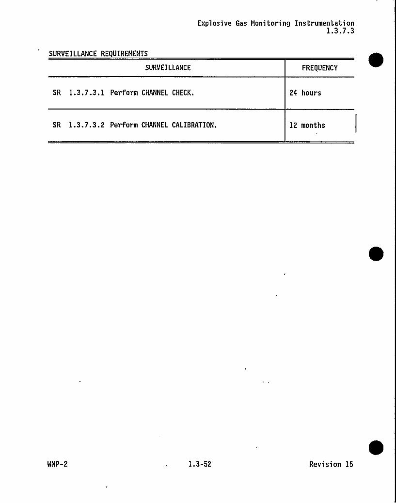
Explosive Gas Monitoring Instrumentation1.3.7.3
SURVEILLANCE REQUIREMENTS
SURVEILLANCE FRE(UENCY
SR 1.3.7.3. 1 Perform CHANNEL CHECK. 24 hours
SR 1.3.7.3.2 Perform CHANNEL CALIBRATION. 12 months
WNP-2 1.3-52 Revision 15

Turbine Overspeed Protection System1.3.7.6
1.3 INSTRUMENTATION
1.3.7.6 Turbine Overspeed Protection System
RFO 1.3.7.6 One Turbine Overspeed Protection System shall be OPERABLE.
APPLICABILITY: MODES 1 and 2.
COMPENSATORY MEASURES
RFO 1.0.4 is not applicable.NOTE
CONDITION REQUIRED COMPENSATORY MEASURE COMPLETION TIME
A. One high pressureturbine valveinoperable.
A.l Restore high pressureturbine valve toOPERABLE status.
72 hours
B. One low pressureturbine valveinoperable.
B.l Restore low pressureturbine valve toOPERABLE status.
72 hours
C. Required CompensatoryMeasure and associatedCompletion Time ofCondition A or B notmet.
OR
Required TurbineOverspeed ProtectionSystem inoperable forreasons other thanCondition A or B.
C.l Isolate the affectedsteam line from thesteam supply.
OR
C.2 Isolate the mainturbine from thesteam supply.
6 hours
6 hours
MNP-2 1.3-,55 Revision 10

Turbine Overspeed Protection System1.3.7.6
SURVEILLANCE REQUIREMENTS
SR 1.0.4 is not applicable.-NOTE
SURVEILLANCE FREQUENCY
SR 1.3.7.6.1 -NOTENot required to be performed until24 hours after valve has been opened withadequate steam flow available.
Cycle each of the following valvesthrough at least one complete cycle fromthe running position for the overspeedprotection control system, the electricaloverspeed trip system, and the mechanicaloverspeed trip system:
a. Four high pressure turbine throttlevalves;
b. Six low pressure turbine reheat stopvalves;
c. Four high pressure turbine governorvalves; and
d. Six low pressure turbine interceptorvalves.
92 days
SR 1.3.7.6.2 Perform CHANNEL CALIBRATION. 18 months
SR 1.3.7.6.3 Disassemble at least one of each of theabove valves, perform a visual andsurface inspection of all valve seats,disks and stems and verify nounacceptable flaws or excessivecorrosion. If unacceptable flaws orexcessive corrosion are found, all othervalves of that type shall be inspected.
40 months
WNP-2 1.3-56 Revision 15

Primary Containment Isolation Valves1.6.1.3
Table 1.6.1.3-1 (page ll of 13)Primary Containment Isolation Valves
VALVE FUNCTION AND NUHBER
'AXIHUHISOLATION TINE
VALVE GROUP(a) (Seconds)
4. Other Containment Isolation Valves(continued)
Containment Atmosphere Control(<)(")(H2 Recombiner)
CAC-V-2CAC-FCV-2A,BCAC-V-15CAC-FCV-1A,BCAC-V-11CAC-V-6CAC-V-4CAC-FCV-4A,BCAC-V-13CAC-V-17CAC-FCV-3A,BCAC-V-8
Containment Purge System
CSP-V-5CSP-V-6CSP-V-7CSP-V-8CSP-V-9CSP-V-10
NA
J ~ Reactor Recirculation (Seal Injection)
RRC-V-13A> 8RRC-V-16A, 8
NA
(continued)
(a)
(e)(k)
See Technical Specification Bases 3.3.6. 1 for the isolation signal(s)which operate each group.Hay be opened on an intermittent basis under administrative control.Hay be tested as part of Type A test. If so tested, Type C testresults may be excluded from sum of other Type B and C tests.
WNP-2 1.6-11 Revision 15

Primary Containment Isolation Valves1.6.1.3
Table 1.6.1.3-1 (page 12 of 13)Primary Containment Isolation Valves
VALVE FUNCTION AND NUMBER
MAXIMUMISOLATION TIME
VALVE GROUP(a) (Seconds)
4. Other Containment Isolation Valves(continued)
k. Containment Instrument Air
CIA-V-20CIA-V-21CIA-V-30A,BCIA-V-31A,B
NA
l. 'Post-Accident Sampling System(e)
PSR-V-X73-1PSR-V-X73-2PSR-V-X77A1PSR-V-X77A2PSR-V-X77A3PSR-V-X77A4PSR-V-X80-1PSR-V-X80-2PSR-V-X82-1PSR-Y-X82-2PSR-V-X82-7PSR-V-X82-8PSR-V-X83-1PSR-V-X83-2PSR-V-X84-1PSR-V-X84-2PSR-V-X88-1PSR-V-X88-2
Radiation Monitoring
PI-V-X72f/1PI- V-X73e/1
NA
(continued)
(a)
(e)
See Technical Specification Bases 3.3.6.1 for the isolation signal(s)which operate each group.Hay be opened on an intermittent basis under administrative control.
WNP-2 1.6-12 Revision 7

Area Temperature Monitoring1.7.1
Table 1.7.1-1 (page 1 of 1)Area Temperature Monitoring
AREA TEMPERATURE LIMIT
1. Control Room
2.
3.
4.
Auxiliary Electric Equipment Rooms
Primary Containment (Orywell)
High Pressure Core Spray, Low Pressure Core Spray,Reactor Residual Heat Removal, Reactor CoreIsolation Cooling Rooms
< 104'F
< 104'F
< 150'F
< 150'F
5. Primary Containment Beneath ReactorPressure Vessel
< 165'F
6. Switchgear Rooms < 104'F
WNP-2 1.7-3 Revision 15

Control Room Emergency Chillers1.7.2
1.7 PLANT SYSTEMS
1.7.2 Control Room Emergency Chillers
RFO 1.7.2: Control Room Emergency Chillers shall be OPERABLE.
APPLICABILITY: At all times.
COMPENSATORY MEASURES
CONDITION REQUIRED COMPENSATORY MEASURE COMPLETION TIME
A. One control roomchiller inoperable.
A.l Restore control roomchiller to OPERABLEstatus.
30 days
B. Two control roomchillers inoperable.
B. I Restore one controlroom chiller toOPERABLE status.
14 days
C. Required CompensatoryMeasure and associatedCompletion Times ofCondition A or B notmet.
C. 1 Initiate ProblemEvaluation Request(PER).
24 hours
SURVEILLANCE REQUIREMENTS
SURVEILLANCE FREQUENCY
SR 1.7.2.1 Verify each control room chiller has thecapability to remove control room heatload.
31 days
WNP-2 1.7-4 Revision 15

Feedwater Temperature8 1.1.6
e 8 1.1 REACTIVITY CONTROL SYSTEMS
B 1.1.6 Feedwater Temperature
BASES
BACKGROUND Final feedwater temperature reduction is used at the end ofcycle (EOC) for the purpose of increasing net corereactivity. The EOC is the core exposure at which RATEDTHERMAL POWER (RTP), rated core flow and rated feedwatertemperature would be achieved if all control rods were fullywithdrawn.
Final feedwater temperature reduction is the operation at orbeyond EOC for the purpose of extending the normal fuelcycle by plant operation with a final feedwater temperaturereduced from the normal rated power temperature condition.The process involves feedwater heater manipulations, corereactivity changes, plant maneuvering, and an awareness ofspecial licensing restrictions. The general philosophy isto trade subcooling reactivity for rod and flow reactivityduring the latter portion of the operating cycle.
As part of the original WNP-2 SER (Ref. 1), the SupplySystem was asked to justify that operation with partialfeedwater heating to extend the cycle beyond the normal EOCcondition would not result in a more limiting change inMINIMUM CRITICAL POWER RATIO (MCPR) than that obtained usingthe assumption of normal feedwater heating. The SupplySystem responded that analyses would be provided prior tooperation in that mode, if a decision is made to implementfinal feedwater temperature reduction. As a result,Condition 2.C.(17) was incorporated into the WNP-2 OperatingLicense to prohibit operation with partial feedwater heatingfor the purpose of extending the normal fuel cycle unlessacceptable justification was provided to and approved by theNRC staff.
Operation with partial feedwater heating for the purpose ofextending the normal fuel cycle was approved by AmendmentNo. 77 to the WNP-2 Operating License (Ref. 9). Issuance ofAmendment No. 77 satisfied WNP-2 Operating License Condition2.C.(17).
(continued)
WNP-2 B 1.1-1 Revision 15

Feedwater TemperatureB 1.1.6
BASES (continued)
APPLICABLESAFETY ANALYSES
For the purpose of extending cycle, feedwater temperaturemay be used for reactivity addition to compensate for thereactivity loss due to fuel depletion. The analysisperformed is applicable to core flow values up to themaximum attainable (106 percent of r ated core flow) and tofeedwater temperature reductions as low as 355'F. It isanticipated that a thermal coastdown from rated power withfeedwater temperature reduction of this order is desirable.The analysis also covers a reduction in power by thermalcoastdown to 47% of RTP with feedwater temperature held ator above 355'F.
During a normal feedwater lineup, a feedwater temperature at355'F entering the reactor vessel is achieved atapproximately 47% of RTP. The Requirement for Operabilityclearly does not apply during reactor startups and shutdownswhen reactor power is below the point at which a feedwatertemperature of 355'F is attainable with a normal feedwatersystem lineup.
Prior to reaching the EOC exposure, operation with anabnormal feedwater lineup is permissible because the shortterm effect of increased subcooling is to more stronglybottom peak the axial power shape. This allows a scram tosuppress the flux faster. Compensation for the long termeffect of a pronounced bottom burn can be made by rodpattern adjustments and axial flux shape monitoring.
REQUIREMENTSFOR OPERABILITY
For the purposes of cycle extension, the feedwatertemperature entering the reactor vessel shall not be reducedto < 355'F.
APPLICABILITY MODE 1, after the EOC exposure has been achieved with steadystate THERMAL POWER ) 47% of RTP.
COMPENSATORYMEASURES
A.l A.2 and A.3
With feedwater temperature entering the reactor vessel at avalue < 355'F, initiate corrective action within 15 minutesand restore feedwater temperature to within the limit within2 hours or reduce THERMAL POWER to < 25% of RTP within thenext 4 hours.
(continued)
WNP-2 B 1.1-2 Revision 15
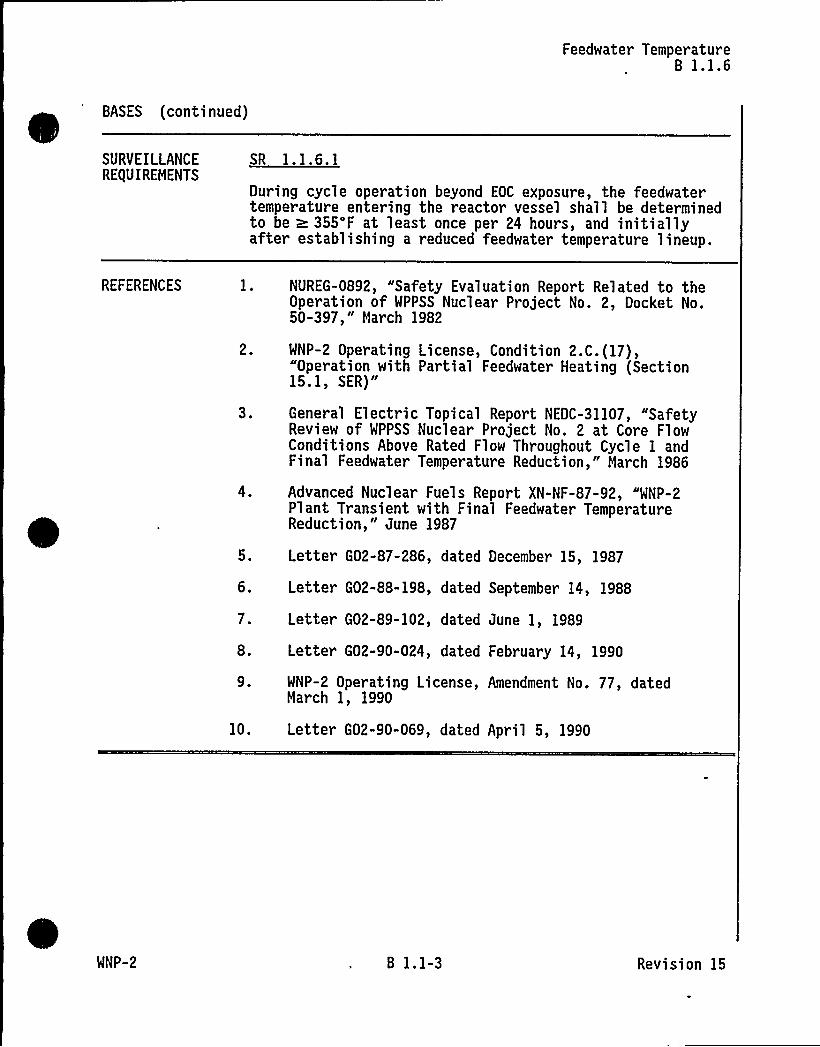
Feedwater TemperatureB 1.1.6
BASES (continued)
SURVEILLANCEREQUIREMENTS
SR 1.1.6.1
During cycle operation beyond EOC exposure, the feedwatertemperature entering the reactor vessel shall be determinedto be ~ 355'F at least once per 24 hours, and initiallyafter establishing a reduced feedwater temperature lineup.
REFERENCES
2.
3.
4,
5.
6.
7.
8.
9.
10.
NUREG-0892, "Safety Evaluation Report Related to theOperation of WPPSS Nuclear Project No. 2, Docket No.50-397," Harch 1982
WNP-2 Operating License, Condition 2.C.(17),Operation with Partial Feedwater Heating (Section
15.1, SER)"
General Electric Topical Report NEDC-31107, "SafetyReview of WPPSS Nuclear Project No. 2 at Core FlowConditions Above Rated Flow Throughout Cycle 1 andFinal Feedwater Temperature Reduction," March 1986
Advanced Nuclear Fuels Report XN-NF-87-92, "WNP-2Plant Transient with Final Feedwater TemperatureReduction," June 1987
Letter G02-87-286, dated December 15, 1987
Letter G02-88-198, dated September 14, 1988
Letter G02-89-102, dated June 1, 1989
Letter G02-90-024, dated February 14, 1990
WNP-2 Operating License, Amendment No. 77, datedNarch 1, 1990
Letter G02-90-069, dated April 5, 1990
WNP-2 B 1.1-3 Revision 15

Control Rod Block Instrumentation8 1.3.2.1
B 1.3 INSTRUMENTATION
B 1.3.2.1 Control Rod Block Instrumentation
BASES
BACKGROUND The purpose of the control rod block instrumentation is tomitigate rod withdrawal errors. Control rods provide theprimary means for control of reactivity changes. The mostsignificant sour ce of reactivity changes during powerincrease is due to control rod withdrawal. Control rodblock instrumentation includes channel sensors, logiccircuitry, switches, and relays arranged so that a trip inany channel will result in a control rod block (Ref. 1).
The Average Power Range Monitoring (APRM) instrumentationwill initiate a rod block to prevent control rod withdrawalif the average core flux exceeds mode switch dependentupscale setpoints. Downscale (MODE 1 only) and INOPgenerated rod blocks prevent rod withdrawal if the channelis not operating as expected.
The Source Range Monitor (SRH) instrumentation provides arod block to prevent control rod withdrawal if the SRH isnot fully inserted into the core when the count level isbelow the retract permissive setpoint. This is to assurethat the SRM is correctly inserted when it must be reliedupon to provide neutron flux level information. The SRMinstrumentation also provides a rod block if the localizedneutron flux exceeds a predetermined setpoint. This is toassure that the SRH is correctly retracted during a reactorstartup. The SRM also provides a rod block if the localizedneutron flux falls below a predetermined setpoint, or isinoperative during control rod manipulations. This is toensure that the SRH is correctly inserted and responding tothe neutron flux signal.
The Intermediate Range Monitors (IRH) instrumentationprovides a rod block to prevent control rod withdrawal ifthe IRM is not fully inserted into the core when in MODE 2or 5. This is to assure that no control rod is withdrawnduring low neutron flux level operations unless properneutron monitoring capability is available. The IRMinstrumentation provides a rod block if the localizedneutron flux exceeds a predetermined setpoint.. This is toassure that no control rod is withdrawn unless the IRMinstrumentation is correctly upranged during a reactorstartup. This rod block also provides a means to stop rod
continued
WNP-2 B 1.3-1 Revision 15

Control Rod Block InstrumentationB 1.3.2.1
BASES
BACKGROUND(continued)
withdrawal in time to avoid conditions requiring ReactorProtection System (RPS) action (scram) in the event that arod withdrawal error is made during low neutron flux leveloperations. The IRM instrumentation provides a rod block toprevent control rod withdrawal if the IRM count level isdownscale except when the IRM range switch is on the lowestrange, or is inoperative. This assures that no control rodis withdrawn unless the neutron flux is being correctlymonitored.
The scram discharge volume (SDV) high level instrumentationwill initiate a rod block when the level is above thesetpoint, or the SDV high water trip is bypassed. Thisassures that no control rod is withdrawn unless the highdischarge level trip is in service, and enough capacity isavailable in the SDV to accommodate a scram.
The reactor coolant recirculation flow unit instrumentationprovides total recirculation loop flow signals to the APRMand rod block monitor (RBM) systems for generation of flowbiased settings for RPS and rod block trips. The reactorcoolant recirculation flow units will generate a rod blockwhen any channel indicates high flow, a mis-match betweenchannels or a INOP condition to prevent rod withdrawal ifthe channel is not operating as expected.
APPLICABLESAFETY ANALYSES
The control rod block instrumentation supports theinitiation of a rod block when initiating conditions exceedpreset limits.
RE(UIREMENTSFOR OPERABILITY
1. Tri Set oint Allowances
Trip setpoints are those predetermined values of output atwhich an action should take place. The setpoints arecompared to the actual process parameter (e.g., reactorpower), and when the measured output value of the processparameter exceeds the setpoint, the associated device (e:g.,trip unit) changes state. The actual setpoints arecalibrated consistent with applicable setpoint methodology.Nominal trip setpoints are specified in the setpointcalculations. The nominal setpoints are selected to ensurethat the setpoints do not exceed the Allowable Valuesbetween successive CHANNEL CALIBRATIONS. Operation with a
continued
WNP-2 B 1.3-2 Revision 7

Control Rod Block InstrumentationB 1.3.2.1
BASES
SURVEILLANCEREQUIREMENTS
SR 1.3.2.1.4 (continued)
Performance of a CHANNEL CALIBRATION every 18 months ensuresthat the instrumentation used for low power operation iscalibrated to account for instrument drift betweensuccessive calibrations consistent with the plant specificsetpoint methodology.
SR 1.3.2.1.5
Performance of a LOGIC SYSTEM FUNCTIONAL TEST every24 months demonstrates the OPERABILITY of the required rodblock trip logic through each activity control path of theReactor Manual Control System (RMCS) for a specific RMCSinput and reactor mode switch position. The functionaltesting of APRM, SRM, IRM, SDV and reactor coolantrecirculation flow, in SR 1.3.2. 1. 1 through SR 1.3.2. 1.4,overlap this Surveillance to provide complete testing ofeach Function. Each CHANNEL FUNCTIONAL TEST and CHANNELCALIBRATION verifies the channel through the common pointwhere the channels lose their identity to the RMCS inputs(Npd, Nu, Npu, Hw). Several channels are combined into theRMCS mode dependent logic to develop the rod block outputsignal. The LOGIC SYSTEM FUNCTIONAL TEST is summarized as averification of each RMCS activity control path resulting inrod blocks for Npd, Npu and Hw inputs in MODE 1; Nu, Npu andHw inputs in MODE 2; and Nu for MODE 5. The 24 monthFrequency is based on the need to perform this Surveillanceunder the conditions that apply during a plant outage due tothe reactor mode switch inputs.
REFERENCES 1. FSAR, Section 7.7.1.2.2.2.
2. FSAR, Section 15.4.1.
3. FSAR, Section 15.4.2.
WNP-2 B 1.3-7 Revision 15

Explosive Gas Monitoring InstrumentationB 1.3.7.3
B 1.3 INSTRUMENTATION
~ ~B 1.3.7.3 Explosive Gas Monitoring Instrumentation
BASES
BACKGROUND The Off-Gas Treatment System is the principle pathway forthe release of gaseous radioactivity to the environmentduring normal plant operations. The Off-Gas TreatmentSystem is designed to limit dose to offsite persons fromroutine station releases to significantly less than thelimits specified in 10 CFR Part 20 and Part 50 and tooperate within the emission rate limits established in theTechnical Specifications.
Hydrogen and oxygen are produced in a boiling water reactor(BWR) by the radiolysis of water. The hydrogen and oxygenproduced, along with fission products and othernoncondensible gases, are removed from the main condenser bya steam jet air ejector and exhausted to the Off-GasTreatment System. The potential exists for hydrogen andoxygen to exist in flammable or explosive concentrations.The BWR industry has experienced a number of fires in theOff-Gas Treatment System. A catalytic recombiner isprovided in the Off-Gas Treatment System to recombinehydrogen and oxygen.
The Off-Gas Treatment System is designed to maintain thehydrogen concentration upstream of the recombiner to lessthan the flammable limit (4% by volume) by steam dilution.The hydrogen recombiner is designed to ensure that thehydrogen concentration at the outlet is less than 1% on adry basis.
There are two hydrogen analyzers (explosive gas monitors) tomonitor the hydrogen concentration downstream of thehydrogen recombiner. The hydrogen concentration is measuredin volume percent and is indicated and recorded in thecontrol room. There is also an independent alarmannunciator for high hydrogen concentration (> 1%).Calibration checks are accomplished automatically atperiodic intervals by isolating the off-gas process line andadmitting a calibration gas.
continued
WNP-2 8 1.3-35 Revision 7

Explosive Gas Monitoring InstrumentationB 1.3.7.3
BASES
BACKGROUND(continued)
The Off-Gas Treatment System design eliminates ignition, sources, so that a hydrogen detonation is highly unlikely in
the event of a recombiner failure. Also the system isdesigned to be detonation resistant.
APPLICABLESAFETY ANALYSES
The explosive gas monitoring instrumentation is not usedfor, nor is capable of, detecting a significant abnormaldegradation of the reactor coolant pressure boundary.
The explosive gas monitoring instrumentation is not used tomonitor any process variable that is an initial condition ofa design basis accident (DBA) or transient. Excessivesystem hydrogen is not an indication of a DBA or transient.
The explosive gas monitoring instrumentation is not part ofa primary success path in the mitigation of a DBA ortransient.
REQUIREMENTSFOR OPERABILITY
One Hain Condenser Off-Gas Treatment System hydrogen monitorshall be OPERABLE.
An OPERABLE hydrogen monitor consists of a hydrogen analyzer'kid(A or B), the recorder channel in the main control room
(MCR) on OG-H2R-605 (A or B), the high hydrogen alarm in theMCR for the corresponding channel and the common support
!
equipment.
APPLICABILITY During Hain Condenser Off-Gas Treatment System operation(steam jet-air ejectors are in operation).
COMPENSATORYMEASURES
A.1
If there are no OPERABLE explosive gas monitor instrumentsand the Main Condenser Off-gas Treatment System is inoperation, then monitor (Chemistry will take grab sample andanalyze) the Hain Condenser Off-gas Treatment Systemhydrogen concentration within 8 hours, and once per 8 hoursthereafter, and within 8 hours from discovery of each changein recombiner temperature or THERMAL POWER.
A Note has been provided that states RFO 1.0.3 is notapplicable because adequate Compensatory Measures areprovided in the RFO.
WNP-2 B 1.3-36
(continued)
Revision 15

Explosive Gas Honitoring InstrumentationB 1.3.7.3
BASES (continued)
SURVEILLANCEREQUIREMENTS
SR 1.3.7.3.1
Performance of the CHANNEL CHECK once every 24 hours ensuresthat a gross failure of instrumentation has not occurred. ACHANNEL CHECK is normally a comparison of the parameterindicated on one channel to a similar parameter on the otherchannel. It is based on the assumption that instrumentchannels monitoring the same parameter should readapproximately the same value. Significant deviationsbetween instrument channels could be an indication ofexcessive instrument drift in one of the channels, orsomething even more serious. A CHANNEL CHECK will detectgross channel failure; thus, it is key to verifying that theinstrument continues to operate properly between eachCHANNEL CALIBRATION.
Agreement criteria are determined by the plant staff basedon a combination of the channel instrument uncertainties,including indication and readability. If a channel isoutside the criteria, it may be an indication that theinstrument has drifted outside of its limit.The Frequency is based upon operating experience thatdemonstrates less formal, but more frequent, checks ofchannels during normal operational use of the displaysassociated with the channels required by the RFO.
SR 1.3.7.3.2
CHANNEL CALIBRATION is a complete check of the instrumentloop and the sensor. This test verifies the channelresponds to the measured parameter within the necessaryrange and accuracy. CHANNEL CALIBRATION leaves the channeladjusted to account for instrument drift between successivecalibrations consistent with the plant specific setpointmethodology.
The Frequency is based upon the assumption of a 12 monthcalibration interval based on industry experience, vendorrecommendation, and the nitrogen purging which functions asan auto calibration.
(continued)
WNP-2 8 1.3-37 Revision 15

Explosive Gas Monitoring InstrumentationB 1.3.7.3
BASES (continued)
REFERENCES 1. Technical Specification 5.5.8.
2. Technical Specification 3.7.5.
3. FSAR, Section 11.3.
WNP-2 B 1.3-38 Revision 15~

Control Room Emergency ChillersB 1.7.2
BASES
COMPENSATORYMEASURES
(continued)
is expected that personnel could tolerate elevated controlroom temperatures for several days with minimal performancedegradation, personnel rotation would provide an added levelof assurance.
The plant could also restore radwaste chilled water or othercooling water supplies to reduce the control roomtemperature.
SURVEILLANCERE(UIREMENTS
A conservative monthly Surveillance Requirement has beenidentified to establish a data base of equipment failurerates. Acquisition of sufficient data may be used at afuture time to revise the surveillance interval based onequipment reliability and operability trends.
The monthly surveillance consists of operating each controlroom chiller with the control room heat load applied for24 hours. The chillers are required to maintain the controlroom temperature at 75'F + 3'ry bulb to satisfy thehabitability limit of 85'F.
The monthly chiller OPERABILITY check is performed under thepreventive maintenance process and scheduled and tracked inaccordance with PPM 1.5. 13 and 1.3.71. In addition, theapplicable Inservice Testing Program surveillance procedureprovides assurance of control chilled water pumpOPERABILITY.
REFERENCES
2.
3.
System Description No. 82-RSY-13-5-T6, Control Room,Cable Room and Critical Switchgear Rooms - HVAC(CR-HVAC), dated 2/17/91.
FSAR Section 6.4.2.2.
FSAR Section 9.4.1. 1.
4. NUREG/CR-3786, A Review of Regulatory RequirementsGoverning Control Room Habitability Systems, Sandi a-National Laboratories, dated August 1984.
continued
WNP-2 B 1.7-7 Revision 15

Control Room Emergency ChillersB 1.7.2
BASES
REFERENCES(continued)
5.
6.
7.
8.
9.
10.
Industrial Ventilation, Manual of RecommendedPractices, High Environmental Dry and Wet BulbTemperatures That Can Be Tolerated In Daily Work ByHealthy Acclimatized Men Wearing Warm WeatherClothing, 14th edition.
Supply System to NRC letter No. G02-94-126, Reply toNotice of Violation 94-12, dated May 27, 1994.
Supply System calculation number ME-02-93-52, CoolingLoads for the Control Room Under Normal and AccidentConditions, Rev. 0.
WNP-2, PPM 1.3.71, Work Closeout Activities.
WNP-2, PPM 1.5.13, Scheduled Maintenance System.
WNP-2 PPM 4.10.2.5, Control Room High Temperature.
WNP-2, PPM OSP-CCH/IST-(701, Control Room ChilledWater Pump Operability.
WNP-2 B 1.7-8 Revision 10

24 VDC SourcesB 1.8.4
BASES
SURVEILLANCEREQUIREMENTS
SR 1.8.4.8 (continued)
Either the battery performance discharge test or themodified performance discharge test is acceptable forsatisfying SR 1.8.4.8; however, only the modifiedperformance discharge test may be used to satisfy SR 1.8.4.8while satisfying the requirements of SR 1.8.4.7 at the sametime.
The acceptance criteria for this Surveillance is consistentwith IEEE-450 (Ref. 4) and IEEE-485 (Ref. 5) for the 24Vbatteries. These references recommend that the battery bereplaced if its capacity is below 80% of the manufacturer'srating, since IEEE-485 (Ref. 5) recommends using an agingfactor of 125% in the battery sizing calculations. Acapacity of 80% for the 24V battery shows that the batteryis getting old and capacity will decrease more rapidly, evenif there is ample capacity to meet the load requirements.
The Surveillance Frequency for this test is normally60 months. If the battery shows degradation, or if thebattery has reached 85% of its expected life and capacity is( 100% of the manufacturer's rating, the SurveillanceFrequency is reduced to 12 months. However, if the batteryshows no degradation but has reached 85% of its expectedlife, the Surveillance Frequency is only reduced to24 months for batteries that retain capacity ~ 100% of themanufacturer's rating. Degradation is indicated, accordingto IEEE-450, 1975 (Ref. 6), when the battery capacity dropsby more than 10% relative to its average on previousperformance tests or when it is below 90% of themanufacturer's rating. The 12 month and 60 monthFrequencies are consistent with the recommendations inIEEE-450 (Ref. 4). The 24 month Frequency is derived fromthe recommendations in IEEE-450 (Ref. 4).
REFERENCES 1. FSAR, Section 8.3.2. 1.2.
2. Technical Specification 3.3. 1. 1.
3. WNP-2 Calculation 2.05.01, Rev. 8, February 1990.
4. IEEE Standard 450, 1987.
continued
WNP-2 B 1.8-7 Revision 15

24 VDC SourcesB 1.8.4
BASES
REFERENCES(continued)
5. IEEE Standard 485, 1983.
6. IEEE Standard 450, 1975.
WNP-2 B 1.8-8 Revision 7

24 VDC Battery ParametersB 1.8.6
BASES
SURVEILLANCERE(UIREHENTS
Table 1.8.6-1 (continued)
The specific gravity readings are corrected for actualelectrolyte temperature and level. For each 3'F (1.67'C)above 77'F (25'C), 1 point (0.001) is added to the reading;1 point is subtracted for each 3'F below 77'F. The specificgravity of the electrolyte in a cell increases with a lossof water due to electrolysis or evaporation. Levelcorrection will be in accordance with manufacturer'srecommendations.
Category B defines the normal parameter limits for eachconnected cell. The term "connected cell" excludes anybattery cell that may be jumpered out.
The Category B limits specified for electrolyte level andfloat voltage are the same as those specified for Category Aand have been discussed above. The Category B limitspecified for specific gravity for each connected cell is~ 1. 195 (0.020 below the manufacturer's fully charged,nominal specific gravity) with the average of all connectedcells > 1.205 (0.010 below the manufacturer's fully charged,nominal specific gravity). These values are based onmanufacturer's recommendations. The minimum specificgravity value required for each cell ensures that a cellwith a marginal or unacceptable specific gravity is notmasked by averaging with cells having higher specificgravities.
Category C defines the limit for each connected cell. Thesevalues, although reduced, provide assurance that sufficientcapacity exists to perform the intended function andmaintain a margin of safety. When any battery parameter isoutside the Category C limit, the assurance of sufficientcapacity described above no longer exists and the batterymust be declared inoperable.
The Category C limit specified for electrolyte level (abovethe top of the plates and not overflowing) ensure that theplates suffer no physical damage and maintain adequateelectron transfer capability. The Category C limit forfloat voltage is based on IEEE-450, Appendix C (Ref. 2),which states that a cell voltage of 2.07 V or below, underfloat conditions and not caused by elevated temperature ofthe cell, indicates internal cell problems and may requirecell replacement.
continued
WNP-2 B 1.8-13 Revision 7

24 VDC Battery Parameter sB.l.8.6
BASES
SURVEILLANCERE(UIREHENTS
Table 1.8.6-1 (continued)
The Category C limit of average specific gravity (a 1. 195),is based on manufacturer's recommendations (0.020 below themanufacturer's recommended fully charged, nominal specificgravity). In addition to that limit, it is required thatthe specific gravity for each connected cell must be no lessthan 0.020 below the average of all connected cells. Thislimit ensures that a cell with a marginal or unacceptablespecific gravity is not masked by averaging with cellshaving higher specific gravities.
The footnotes to Table 1.8.6-1 that apply to specificgravity are applicable to Category A, B, and C specificgravity. Footnote b requires the above mentioned correctionfor electrolyte level and temperature, with the exceptionthat level correction is not required when battery chargingcurrent is ( 2 amps on float charge. This current provides,in general, an indication of acceptable overall batterycondition. Because of specific gravity gradients that areproduced during the recharging process, delays of severaldays may occur while waiting for the specific gravity tostabilize. A stabilized charging current is an acceptablealternative to specific gravity measurement for determiningthe state of charge. This phenomenon is discussed inIEEE-450 (Ref. 2). Footnote c allows the float chargecurrent to be used as an alternate to specific gravity forup to 7 days following a battery recharge. Within 7 dayseach connected cell's specific gravity must be measured toconfirm the state of charge. Following a minor batteryrecharge (such as an equalizing charge that does not followa deep discharge), specific gravity gradients are notsignificant, and confirming measurements may be made in lessthan 7 days.
REFERENCES 1. FSAR, Section 8.3.2.1.2.
2. IEEE Standard 450, 1987.
WNP-2 B 1.8-14 Revision 15

24 VDC Distribution SystemB 1.8.7
BASES
COMPENSATORYMEASURES
(continued)
With one or more 24 VDC electrical power subsysteminoperable, immediately declare required supported equipmentinoperable. OPERABLE DC electrical power distributionsubsystems require the associated buses to be energized totheir proper voltage.
SURVEILLANCERE(UIREMENTS
SR 1.8.7.1
This Surveillance verifies that the DC electrical powerdistribution systems are functioning properly, with thecorrect circuit breaker alignment. The correct breakeralignment ensures the appropriate separation andindependence of the electrical divisions is maintained andpower is available to each required bus. The verificationof energization of the buses ensures that the required poweris readily available for motive as well as control functionsfor critical system loads connected to these buses. Thismay be performed by verification of absence of low voltagealarms or by verifying a load powered from the bus isoperating. The 7 day Frequency takes into account theredundant capability of the DC electrical power distributionsubsystems and other indications available in the controlroom that alert the operator to subsystem malfunctions.
REFERENCES 1. FSAR, Section 8.3.2.1.2.
2. Technical Specification 3.3. 1. 1.
WNP-2 B 1.8-17 Revision 15

Circuits Inside Primary ContainmentB 1.8.9
B 1.8 ELECTRICAL POWER SYSTEMS
B 1.8.9 Circuits Inside Primary Containment
BASES
BACKGROUND Primary containment electrical penetrations and penetrationconductors are protected by either deenergizing powercircuits not required during reactor operation or bydemonstrating the OPERABILITY of primary and backupovercurrent protection devices by periodic surveillances.Those AC circuits inside primary containment, which are keptnormally deenergized, do not participate in plant safetyactions. These circuits are primarily for lighting, utilityoutlets, and convenience power to be used for plantwalkdowns, maintenance, and in-situ tests and/orobservations. These circuits are non Class 1E.
APPLICABLE The AC circuits inside primary containment are kept normallySAFETY ANALYSES deenergized and do not participate in plant safety actions.
Thus, these circuits have no impact on plant safety systems.
REQUIREMENTS The following AC circuits shall be deenergized:FOR OPERABILITY
a. Circuits off of breakers 2AR and 8AR of E-MC-BC.
b. Circuits off of panel E-LP-6BAG.
c. Circuits off of panel E-LP-3DAG.
d. Circuits off of breakers 2BL, 1D, and 2CR of E-MC-3DA.
APPLICABILITY MODES 1, 2, and 3, except during entries into the drywell.This is consistent with the applicability of other primarycontainment requirements. Primary containment OPERABILITYis not required in MODES 4 and 5. Additionally, thesecircuits may be energized to support maintenance activitiesduring outages.
(continued)
WNP-2 B 1.8-18 Revision 7

Circuits Inside Primary ContainmentB 1.8.9
BASES (continued)
COHPENSATORYMEASURES
A.l
With one or more required circuits energized, deenergize therequired circuit within 4 hours. This Completion Time isconsistent with other primary containment requirements.
SURVEILLANCERE(UIREHENTS
SR 1.8.9. 1 and SR 1.8.9.2
Every 24 hours verify that each required circuit that is notlocked, sealed, or otherwise secured in the deenergizedcondition is deenergized.
Every 31 days verify that each required circuit that islocked, sealed, or otherwise secured in the deenergizedposition has remained deenergized. The 31 day Frequency isacceptable considering the additional administrativecontrols to assure the required deenergized position ismaintained.
REFERENCES 1. FSAR, Section 1.8.
2. FSAR, Section 3.8.2.2.4.
3. FSAR, Section 7.1.2.3.
4. FSAR, Section 8.3.1.
WNP-2 B 1.8-19 Revision 15

HOV Thermal Overload ProtectionB 1.8.11
B 1.8 ELECTRICAL POWER SYSTEMS
B 1.8. 11 Motor Operated Valve (MOV) Thermal Overload Protection
BASES
BACKGROUNO For valves with thermal overload protection (i.e., trip onoverload condition), the valve function should beaccomplished prior to overload trip. The overloadprotection for these valves is meant to take precedence overthe valve function. If the overload condition occurs duringvalve operation, the electric circuit will open to protectthe equipment. In case of failure of the overloadprotection operation to disconnect the load, the equipmentmay suffer potential damage.
Motor thermal overloads for Class lE MOVs are selected twosizes larger than the normally selected thermal overload.(This .approximates 140% of motor full load amperage.)Selection of overloads in this range permits Class 1E MOVsto operate for extended periods of time at moderateoverloads; tripping occurs just prior to motor damage.
APPLICABLE The bypassing of the HOV thermal overload protectionSAFETY ANALYSES continuously or during accident conditions ensures that the
thermal overload protection will not prevent safety relatedvalves from performing their function. The SurveillanceRequirements for demonstrating the bypassing of the thermaloverload protection continuously and during accidentconditions are in accordance with Regulatory Guide 1. 106"Thermal Overload Protection for Electric Motors on MotorOperated Valves," Revision 1, March 1977.
REQUIREMENTS The thermal overload protection for each MOV shown inFOR OPERABILITY Table 1.8.11-1 shall be OPERABLE.
APPLICABILITY Whenever the HOV is required to be OPERABLE.
(continued)
WNP-2 B 1.8-23 Revision 7

HOV Thermal Overload ProtectionB 1.8.11
BASES (continued)
COMPENSATORYMEASURES
A.l and B.l
With one or more HOV thermal overloads inoperable,continuously bypass the inoperable HOV thermal overloadwithin 8 hours. If the thermal overload is not bypassed,the HOV must be declared inoperable and any applicableRequired Compensatory Measures (because the MOV isinoperable) must be taken.
SURVEILLANCEREQUIREMENTS
SR 1.8.11.1
Every 18 months perform a CHANNEL CALIBRATION of arepresentative sample of a 25% on a rotating basis, on theHOV thermal overloads.
REfERENCES 1. FSAR, Section 8.3.1.1.9.
WNP-2 B 1.8-24 Revision 15
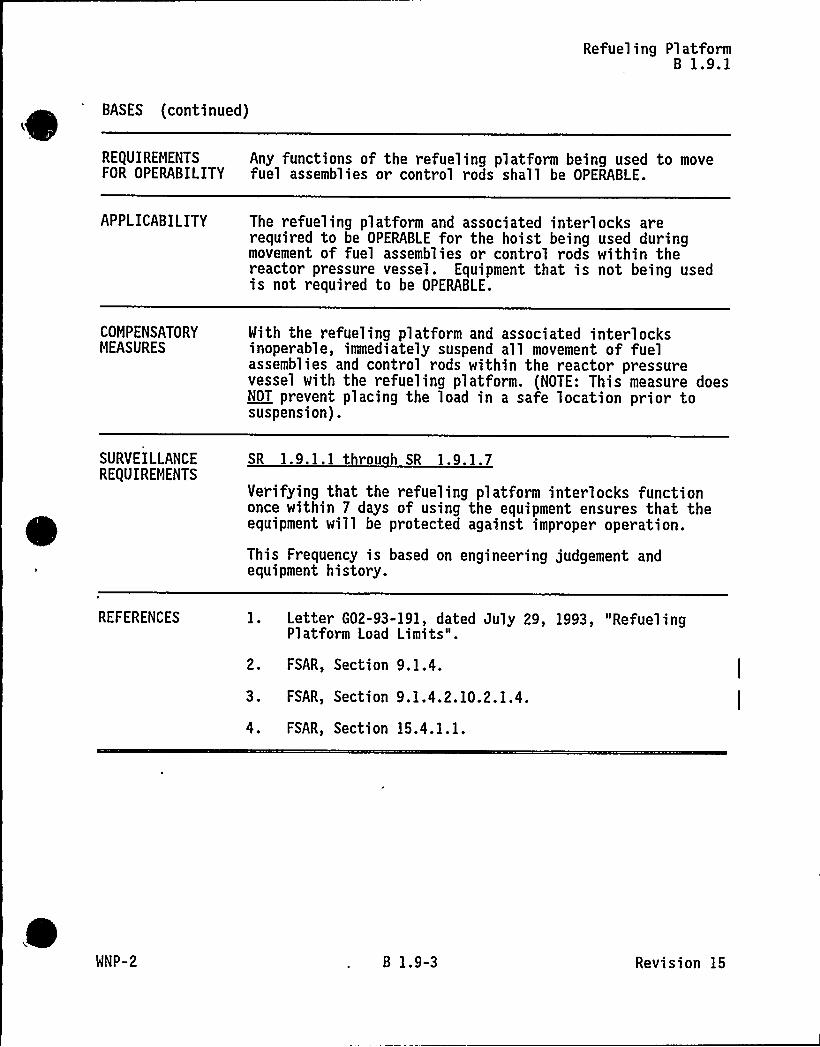
Refueling PlatformB 1.9.1
BASES (continued)
REQUIREMENTS Any functions of the refueling platform being used to moveFOR OPERABILITY fuel assemblies or control rods shall be OPERABLE.
APPLICABILITY The refueling platform and associated interlocks arerequired to be OPERABLE for the hoist being used duringmovement of fuel assemblies or control rods within thereactor pressure vessel. Equipment that is not being usedis not required to be OPERABLE.
COMPENSATORYMEASURES
With the refueling platform and associated interlocksinoperable, immediately suspend all movement of fuelassemblies and control rods within the reactor pressurevessel with the refueling platform. (NOTE: This measure doesNOT prevent placing the load in a safe location prior tosuspension).
SURVEILLANCERE(UIREMENTS
SR 1.9.1.1 throu h SR 1.9.1.7
Verifying that the refueling platform interlocks functiononce within 7 days of using the equipment ensures that theequipment will be protected against improper operation.
This Frequency is based on engineering judgement andequipment history.
REFERENCES 1. Letter G02-93-191, dated July 29, 1993, "RefuelingPlatform Load Limits".
2. FSAR, Section 9. 1.4.
3. FSAR, Section 9.1.4.2.10.2.1.4.
4. FSAR, Section 15.4.1.1.
WNP-2 B 1.9-3 Revision 15

Crane TravelB 1.9.2
B 1.9 REFUELING OPERATIONS
B 1.9.2 Crane Travel
BASES
BACKGROUND To prevent transporting loads over the spent fuel storagepool that are greater than the allowed load limit, the cranetravel is restricted by interlocks (Ref 1). Theseinterlocks are established so that the crane will stop if anattempt is made to transport material over the spent fuelstorage pool.
The interlocks are bypassed only when it is necessary tooperate the crane in the fuel pool area in conjunction withactivities associated with fuel handling and storage.During the occasions when the interlocks are bypassed,administrative controls are used to prevent the crane fromcarrying loads that are not necessary for fuel handling orstorage, and which are in excess of the rack design dropload (one fuel assembly at four feet above the top of thefuel rack) (Ref 2). Load limits are applied to the loadscarried over the spent fuel. Loads over a given weight arelimited as to the height that they can be carried over thespent fuel storage pool.
APPLICABLESAFETY ANALYSES
The restriction on movement of loads in excess of thenominal weight of a fuel assembly over other fuel assembliesin the storage pool ensures that in the event this load isdropped: (1) the activity release will be limited to thatassumed in the fuel handling accident (Ref. 3); and (2) anypossible distortion of fuel in the storage racks will notresult in a critical array. This assumption is consistentwith the activity release assumed in the safety analyses.The most severe fuel handling accident from a radiologicalviewpoint is dropping a fuel assembly onto the top of thecore. This accident analysis bounds the accident for adropped fuel assembly over the spent fuel pool (Ref 3).
The ability to withstand a dropped fuel bundle is includedin the design of the spent fuel racks (Ref 4).
RE(UIREMENTSFOR OPERABILITY
The load and height of a load over the spent fuel pool shallbe within the limits of the graph (Figure 1.9.2-1).
(continued)
WNP-2 B 1.9-4 Revision 7

Crane TravelB 1.9.2
BASES (continued)
APPLICABILITY The load and load height limits are required whenever thereis irradiated fuel in the spent fuel pool.
COMPENSATORYMEASURES
A note has been added to state that the requirements ofRFO 1.0.3 are not applicable.
When the load and height limitations are not met,immediately initiate actions to move the crane load fromover the spent fuel storage pool racks.
SURVEILLANCEREQUIREMENTS
SR 1.9.2.1
The system functional test involves demonstrating that thecrane interlocks and physical stops that prevent cranetravel with loads in excess of 1500 pounds over fuelassemblies in the pent fuel pool rack are OPERABLE.
This Surveillance Requirement is only required when thecrane is in use. Verifying crane travel limits functionevery 7 days when the crane is in use ensures that theequipment will be protected against improper operation.
REFERENCES 1. FSAR, Section 9.1.2.3.3.
2. FSAR, Section 9.1.2.3.2.
3. FSAR, 15.7.4.
4. FSAR 9.1.2.1.1.1.
WNP-2 B 1.9-5 Revision 15