
Nortel CS1000 Maintenance Manual - PbxMechanic
200
Nortel Communication Server 1000 Communication Server 1000E Maintenance Release: 7.0 Document Revision: 04.01 www.nortel.com NN43041-700 .
Transcript of Nortel CS1000 Maintenance Manual - PbxMechanic
Nortel Communication Server 1000
Communication Server 1000EMaintenanceRelease: 7.0Document Revision: 04.01
www.nortel.com
NN43041-700.
Nortel Communication Server 1000Release: 7.0Publication: NN43041-700Document release date: 4 June 2010
Copyright © 2004-2010 Nortel Networks. All Rights Reserved.
While the information in this document is believed to be accurate and reliable, except as otherwise expresslyagreed to in writing NORTEL PROVIDES THIS DOCUMENT "AS IS" WITHOUT WARRANTY OR CONDITION OFANY KIND, EITHER EXPRESS OR IMPLIED. The information and/or products described in this document aresubject to change without notice.
Nortel, Nortel Networks, the Nortel logo, and the Globemark are trademarks of Nortel Networks.
All other trademarks are the property of their respective owners.
.
3.
ContentsNew in this release 7Navigation 7Feature changes 7Other changes 7
Revision History 7
How to get help 11Contents 11Getting help from the Nortel web site 11Getting help over the telephone from a Nortel Solutions Center 11Getting help from a specialist by using an Express Routing Code 12Getting help through a Nortel distributor or reseller 12
Overview 13Subject 13Applicable systems 13Intended audience 13Conventions 13Related information 15
Precautions 17Contents 17General precautions 17Circuit cards 17
Communicating with the system 19Contents 19Introduction 19System terminal access for CP PIV Call Processors 19System terminal access for Gateway Controllers 21Element Manager 22Accessing the system 22
Access to the Co-resident platform 26
Hardware maintenance tools 29Contents 29
Nortel Communication Server 1000Communication Server 1000E Maintenance
NN43041-700 04.01 4 June 2010
Copyright © 2004-2010 Nortel Networks. All Rights Reserved.
.
4
Introduction 29Alarm/fan module features 29Compact flash cards 32Circuit card features 33
NTDW53 Common Processor Dual Core card 33NTDW61 Common Processor Pentium Mobile card 35NTDW61 CP PM Signaling Server 38NT4N39 PIV Call Processor features 39CP PIV System Utility card features 40NTDW20 Media Gateway Extended Peripheral Equipment Controller (MG
XPEC) 42NTDW56 and NTDW59 Common Processor Media Gateway card 43NTDW60 Media Gateway Controller card 43NTDW60 Media Gateway Controller LEDs 43NTDW62, NTDW64, and NTDW78 DSP daughterboards 45NTDW65 Voice Gateway Media Card 46Circuit card LEDs 46Media Card LEDs 46NTAK10 faceplate LEDs 47NTAK79 faceplate LEDs 48NTBK50 faceplate LEDs 49NTAK09 and NTRB21 faceplate LEDs 50
Signaling servers for DTLS 52CP PM faceplates LEDs 53
System alarms 53Line transfer 54External power loss 55
Software maintenance tools 57Contents 57Introduction 57Maintenance applications 58Diagnostic programs 58
Unsuccessful DTLS negotiation 62Diagnostics for Linux Base 62
Media Gateway Controller Local Diagnostic Shells 63Media Gateway Controller log file 65Interactive diagnostics 66Boot MGC to the Gold Image 67
Compact Flash Formatting with MGC Gold Image 68CS1000 Software Logs 68Supported DTLS Ciphers 69Advanced Cryptography Support 69
Nortel Communication Server 1000Communication Server 1000E Maintenance
NN43041-700 04.01 4 June 2010
Copyright © 2004-2010 Nortel Networks. All Rights Reserved.
.
5
Clearing faults 71Contents 71Fault clearing process 71Fault indicators 73Clearing Core Call Server faults 75Clearing Signaling Server faults 80MG 1000E faults 82Clearing Core faults 88Clearing MG 1000E Expansion faults 91Monitoring 100BaseT link voice Quality of Service 95Clearing trunk faults 97Clearing Terminal Server faults 100Clearing IP Phone faults 100
Database management 101Contents 101Tools to backup and restore customer databases 101Equipment Data Dump 102Customer Configuration Backup and Restore 102Coresilient server Backup 107OAM Backup 107
Replacing equipment 109Contents 109Removing the MG 1000E cover 110Replacing the NTDW61 CP PM Call Processor card 110Replacing NTDW61 CP PM Signaling Server equipment 127
CP PM Signaling Server card replacement 127Replacing the NTDW60 Media Gateway Controller card 131Replacing the NTDW62 or NTDW64 DSP daughterboard 133Replacing the NTDW65 Voice Gateway Media Card 134Replacing the NT4N39AA CP PIV Call Processor card 134Replacing the NT4N48 System Utility card 136Replacing the NTDU67 Drive Carrier card (CP PII only) 137Replacing the NTDU64 alarm/fan module 139Replacing the NTDU65 power supply module 139Accessing Media Gateway internal components 142Replacing the NTAK02 SDI/DCH circuit card 143Replacing the NTAK03 TDS/DTR circuit card 144Replacing the NTAK79 or NTBK50 2.0 Mb PRI card 144Replacing the NTAK09 1.5 Mb DTI/PRI card (PRI applications) 147Replacing the NTAK09, NTAK10, or NTRB21 circuit cards (DTI applications) 148Replacing equipment cards 149Replacing the NT5K21 equipment card 150
Nortel Communication Server 1000Communication Server 1000E Maintenance
NN43041-700 04.01 4 June 2010
Copyright © 2004-2010 Nortel Networks. All Rights Reserved.
.
6
Replacing the NTAG26 equipment card 151Replacing the NTAK92 off-premises protection module 151Replacing IP daughterboards 153
Element Manager 155Contents 155Call Server maintenance 155Call Server backup, data dump, and restore 157Signaling Server maintenance 158Media Card maintenance 159LD 36 analog trunk card status 160
Media Card maintenance 161Contents 161Introduction 161Faceplate maintenance display codes 161Replacing a Media Card 166Verify Media Card software and firmware 167IP Line and IP Phone maintenance and diagnostics 167IP line shell commands 168Invoking alarm and log files 169Media Card 32S and DSP daughterboard DSP tests 169
Proactive Voice Quality Management 171Contents 171Introduction 171How voice quality monitoring works 173Feature packaging 175Supported system types 175Feature implementation 175Diagnosing and isolating voice-quality problems 179SNMP interface 180Heterogeneous environments 180
pbxLink connection 183Contents 183Introduction 183pbxLink connection failure detection 183LD 117 STAT SERV enhancement 185
Technical Assistance service 189Contents 189Nortel Technical Assistance Centers 189Services available 191Requesting assistance 193
Nortel Communication Server 1000Communication Server 1000E Maintenance
NN43041-700 04.01 4 June 2010
Copyright © 2004-2010 Nortel Networks. All Rights Reserved.
.

7.
New in this releaseThe following sections details what’s new in Communication Server 1000EMaintenance (NN43041-700) for Nortel Communication Server 1000Release 7.0.
Navigation• “Feature changes” (page 7)
• “Other changes” (page 7)
Feature changesFollowing are the feature changes for this release:
• “Signaling servers for DTLS” (page 52)
• “Unsuccessful DTLS negotiation” (page 62)
Other changesRevision History
June 2010Standard 04.01. This document is up-issued to support CommunicationServer 1000 Release 7.0.
October 2009Standard 03.14. This document is up-issued to reflect changes in technicalcontent for Communication Server 1000 Release 6.0. “NTDW20 MediaGateway Extended Peripheral Equipment Controller (MG XPEC)” (page42) provides information about MG XPEC.
October 2009Standard 03.13. This document is up-issued to update the sectionSoftware maintenance tools.
Nortel Communication Server 1000Communication Server 1000E Maintenance
NN43041-700 04.01 4 June 2010
Copyright © 2004-2010 Nortel Networks. All Rights Reserved.
.
8 New in this release
August 2009Standard 03.12. This document is up-issued to support the new MG 1010media gateway.
June 2009Standard 03.11. This document is up-issued to support CommunicationServer 1000 Release 6.0.
May 2009Standard 03.10. This document is up-issued to support CommunicationServer 1000 Release 6.0. Following are the other changes done for thisRelease:
• UNIStim with DTLS
• SSC is not supported in CS 1000 Release 6.0
• patch conflict management
• supported Ciphers and advanced cryptography for DTLS
• transfer using SFTP client by default during Linux upgrades andinstallations
• memshow command changed to free –b –t -o
May 2009Standard 03.09. This document is up-issued to support CommunicationServer 1000 Release 6.0. This NTP may contain information on or refer toproducts and naming conventions that are not supported in this release.This information is included for legacy purposes and convenience only.This includes but is not limited to items, such as: SSC; ISP 1100; ITGPentium cards; and Media Cards running certain IP Line applications.
July 2008Standard 02.04. This document is issued to support CommunicationServer 1000 Release 5.5.
June 2008Standard 02.03. This document is issued to support CommunicationServer 1000 Release 5.5.
February 2008Standard 02.02. This document is issued to support CommunicationServer 1000 Release 5.5.
December 2007Standard 02.01. This document is issued to support CommunicationServer 1000 Release 5.5.
Nortel Communication Server 1000Communication Server 1000E Maintenance
NN43041-700 04.01 4 June 2010
Copyright © 2004-2010 Nortel Networks. All Rights Reserved.
.
Other changes 9
October 2007Standard 01.03. This document is issued to support CommunicationServer 1000 Release 5.0. Changes to address CR Q01766330.
June 2007Standard 01.02. This document is issued to support CommunicationServer 1000 Release 5.0. Procedures for adding and replacing a CP PMCall Processor card and a Media Gateway Controller card are added.
May 2007Standard 01.01. This document is issued to support CommunicationServer 1000 Release 5.0. This document contains information previouslycontained in the following legacy documents, now retired: CommunicationServer 1000E: Maintenance NN43041-700 and Communication Server1000S: Maintenance NN43041-500.
January 2007Standard 4.00. This document is up-issued to reflect addition of technicalcontent due to CR Q01542505.
July 2006Standard 3.00. This document is up-issued with corrections from CRQ01324850.
August 2005Standard 2.00. This document is up-issued for Communication Server1000 Release 4.5.
September 2004Standard 1.00. This document is issued for Communication Server 1000Release 4.0.
Nortel Communication Server 1000Communication Server 1000E Maintenance
NN43041-700 04.01 4 June 2010
Copyright © 2004-2010 Nortel Networks. All Rights Reserved.
.

10 New in this release
Nortel Communication Server 1000Communication Server 1000E Maintenance
NN43041-700 04.01 4 June 2010
Copyright © 2004-2010 Nortel Networks. All Rights Reserved.
.
11.
How to get help
ContentsThis section contains the following topics:
• “Getting help from the Nortel web site” (page 11)
• “Getting help over the telephone from a Nortel Solutions Center” (page11)
• “Getting help from a specialist by using an Express Routing Code”(page 12)
• “Getting help through a Nortel distributor or reseller” (page 12)
Getting help from the Nortel web siteThe best way to get technical support for Nortel products is from the NortelTechnical Support web site:www.nortel.com/support
This site provides quick access to software, documentation, bulletins, andtools to address issues with Nortel products. From this site, you can:
• download software, documentation, and product bulletins
• search the Technical Support Web site and the Nortel Knowledge Basefor answers to technical issues
• sign up for automatic notification of new software and documentationfor Nortel equipment
• open and manage technical support cases
Getting help over the telephone from a Nortel Solutions CenterIf you do not find the information you require on the Nortel TechnicalSupport web site, and you have a Nortel support contract, you can also gethelp over the telephone from a Nortel Solutions Center.
In North America, call 1-800-4NORTEL (1-800-466-7835).
Nortel Communication Server 1000Communication Server 1000E Maintenance
NN43041-700 04.01 4 June 2010
Copyright © 2004-2010 Nortel Networks. All Rights Reserved.
.
12 How to get help
Outside North America, go to the following web site to obtain the telephonenumber for your region:www.nortel.com/callus
Getting help from a specialist by using an Express Routing CodeTo access some Nortel Technical Solutions Centers, you can use anExpress Routing Code (ERC) to quickly route your call to a specialist inyour Nortel product or service. To locate the ERC for your product orservice, go to:www.nortel.com/erc
Getting help through a Nortel distributor or resellerIf you purchased a service contract for your Nortel product from adistributor or authorized reseller, contact the technical support staff for thatdistributor or reseller.
Nortel Communication Server 1000Communication Server 1000E Maintenance
NN43041-700 04.01 4 June 2010
Copyright © 2004-2010 Nortel Networks. All Rights Reserved.
.
13.
OverviewThis document is a global document. Contact your system supplier or yourNortel representative to verify that the hardware and software describedare supported in your area.
SubjectThis document describes system maintenance for the CS 1000E system.
Note on legacy products and releasesThis NTP contains information about systems, components, and featuresthat are compatible with Nortel Communication Server 1000 Release 7.0software. For more information about legacy products and releases, clickthe Technical Documentation link under Support on the Nortel homepage:
www.nortel.com
Applicable systemsThis document applies to the Communication Server 1000E (CS 1000E)system.
Intended audienceThis document is intended for individuals who configure, maintain, andtroubleshoot CS 1000E systems.
ConventionsIn this document, the Communication Server 1000E (CS 1000E) is referredto generically as system.
In this document, the following Chassis or Cabinets are referred togenerically as Media Gateway:
• Option 11C Mini Chassis (NTDK91) and Chassis Expander (NTDK92)
• Option 11C Cabinet (NTAK11)
Nortel Communication Server 1000Communication Server 1000E Maintenance
NN43041-700 04.01 4 June 2010
Copyright © 2004-2010 Nortel Networks. All Rights Reserved.
.
14 Overview
• MG 1000E Chassis (NTDU14) and Expansion Chassis (NTDU15)
• Media Gateway 1010 (MG 1010) (NTC310)
In this document, the following hardware is referred to generically asServer:
• Common Processor Pentium Mobile (CP PM) card
• Common Processor Media Gateway (CP MG) card
• Common Processor Dual Core (CP DC) card
• Commercial off-the-shelf (COTS) servers
— IBM x306m server (COTS1)
— HP DL320 G4 server (COTS1)
— IBM x3350 server (COTS2)
— Dell R300 server (COTS2)
In this document, the generic term COTS refers to all COTS servers. Theterm COTS1 or COTS2 refers to the specific servers in the preceding list.
In this document, the following hardware is referred to as GatewayController:
• Media Gateway Controller (MGC) card (NTDW60 and NTDW98)
• Common Processor Media Gateway (CP MG) card (NTDW56 andNTDW59)
• Media Gateway Extended Peripheral Equipment Controller (MG XPEC)card
Note: Gateway Controllers run a common MGC loadware. The MGCmaintenance commands are supported on all Gateway Controllerplatforms unless otherwise indicated.
Co-res CS and SS is not supported on COTS1 servers. You can deploy aCOTS1 server as a stand-alone Signaling Server.
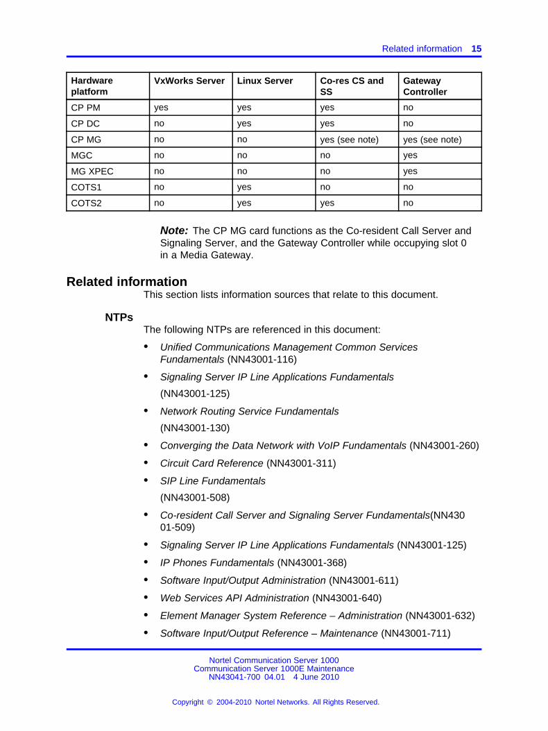
The following table shows CS 1000 Release 7.0 supported roles forhardware platforms.
Table 1Hardware platform supported roles
Hardwareplatform
VxWorks Server Linux Server Co-res CS andSS
GatewayController
CP PIV yes no no no
Nortel Communication Server 1000Communication Server 1000E Maintenance
NN43041-700 04.01 4 June 2010
Copyright © 2004-2010 Nortel Networks. All Rights Reserved.
.
Related information 15
Hardwareplatform
VxWorks Server Linux Server Co-res CS andSS
GatewayController
CP PM yes yes yes no
CP DC no yes yes no
CP MG no no yes (see note) yes (see note)
MGC no no no yes
MG XPEC no no no yes
COTS1 no yes no no
COTS2 no yes yes no
Note: The CP MG card functions as the Co-resident Call Server andSignaling Server, and the Gateway Controller while occupying slot 0in a Media Gateway.
Related informationThis section lists information sources that relate to this document.
NTPsThe following NTPs are referenced in this document:
• Unified Communications Management Common ServicesFundamentals (NN43001-116)
• Signaling Server IP Line Applications Fundamentals
(NN43001-125)
• Network Routing Service Fundamentals
(NN43001-130)
• Converging the Data Network with VoIP Fundamentals (NN43001-260)
• Circuit Card Reference (NN43001-311)
• SIP Line Fundamentals
(NN43001-508)
• Co-resident Call Server and Signaling Server Fundamentals(NN43001-509)
• Signaling Server IP Line Applications Fundamentals (NN43001-125)
• IP Phones Fundamentals (NN43001-368)
• Software Input/Output Administration (NN43001-611)
• Web Services API Administration (NN43001-640)
• Element Manager System Reference – Administration (NN43001-632)
• Software Input/Output Reference – Maintenance (NN43001-711)
Nortel Communication Server 1000Communication Server 1000E Maintenance
NN43041-700 04.01 4 June 2010
Copyright © 2004-2010 Nortel Networks. All Rights Reserved.
.
16 Overview
• Software Input/Output Reference – System Messages (NN43001-712)
• Communication Server 1000 Fault Management – SNMP(NN43001-719)
• Traffic Measurement: Formats and Outputs Reference (NN43001-750)
• Communication Server 1000E Planning and Engineering(NN43041-220)
• Communication Server 1000E Installation and Commissioning(NN43041-310)
• Communication Server 1000E Software Upgrades (NN43041-458)
• Communication Server 1000E Hardware Upgrades (NN43041-464)
OnlineTo access Nortel documentation online, click the TechnicalDocumentation link under Support on the Nortel home page:
www.nortel.com
CD-ROMTo obtain Nortel documentation on CD-ROM, contact your Nortel Networkscustomer representative.
Nortel Communication Server 1000Communication Server 1000E Maintenance
NN43041-700 04.01 4 June 2010
Copyright © 2004-2010 Nortel Networks. All Rights Reserved.
.
17.
Precautions
ContentsThis section contains the following topics:
• “General precautions” (page 17)
• “Circuit cards” (page 17)
General precautionsCS 1000 equipment is based on solid state circuitry that is sensitive tostatic electricity and environmental conditions. Follow the precautions inthis chapter to avoid personal injury and equipment damage.
DANGERTo avoid the danger of electric shock, be careful when workingwith power equipment and connections. Warning notices aredisplayed and must be heeded.
Wear an antistatic wrist strap when handling circuit cards to preventdamage caused by static electricity.
Circuit cardsHandle the circuit cards as follows:
• Wear an antistatic wrist strap before handling circuit cards.
• Handle the cards by the card stiffeners and edges only. Do not touchthe contacts or components.
• Keep the cards installed in the system as much as possible to avoiddirty contacts and unnecessary wear.
• Set the cards on a protective antistatic bag. If an antistatic bag isnot available, hold the card, or set it in a card slot unseated from theconnectors.
• Unpack or handle the cards away from electric motors, transformers,or similar machinery.
Nortel Communication Server 1000Communication Server 1000E Maintenance
NN43041-700 04.01 4 June 2010
Copyright © 2004-2010 Nortel Networks. All Rights Reserved.
.
18 Precautions
• Store the cards in protective packing. Do not stack cards on top ofeach other unless they are packaged.
• Store the cards in a dry dust-free area.
During repair and maintenance procedures:
• Turn off the power switch, if there is one.
• Software-disable the cards, if applicable, before they are removed orinserted.
• Hardware-disable the cards, whenever there is an enable/disableswitch, before they are removed or inserted.
• Insert the cards into compatible slots only.
• Return defective or heavily contaminated cards to a repair center; donot try to repair or clean them.
Nortel Communication Server 1000Communication Server 1000E Maintenance
NN43041-700 04.01 4 June 2010
Copyright © 2004-2010 Nortel Networks. All Rights Reserved.
.
19.
Communicating with the system
ContentsThis section contains the following topics:
• “Introduction” (page 19)
• “System terminal access for CP PIV Call Processors” (page 19)
• “System terminal access for Gateway Controllers” (page 21)
• “Element Manager” (page 22)
• “Accessing the system” (page 22)
IntroductionSend maintenance commands and receive system messages (status anderror messages) by communicating with the system through one or moreof the following input/output devices or management tools:
• TTY or VDT terminal as an input/output device
• PC running terminal emulation software
• RS-232-C compatible printer as an output-only device
• Maintenance telephone as an input-only device
• Element Manager
See Communication Server 1000E Installation and CommissioningNN43041-310 for information about how to connect these devices andmanagement tools.
System terminal access for CP PIV Call ProcessorsTerminal Server
Because each CS 1000E Core Call Server provides only two ports forserial devices, the Terminal Server is used to provide the necessarystandard serial ports for applications and devices that require them, suchas printers and Call Detail Recording (CDR). The Terminal Server is alsoused to connect maintenance terminals and modems for support staff.
Nortel Communication Server 1000Communication Server 1000E Maintenance
NN43041-700 04.01 4 June 2010
Copyright © 2004-2010 Nortel Networks. All Rights Reserved.
.
20 Communicating with the system
The Terminal Server provides an rlogin service that allows serial devicesto establish dedicated connections to pseudo TTY (PTY) ports on the CallServer. (The Terminal Server therefore serves the same purpose as SerialData Interface [SDI] and Multipurpose Serial Data Link [MSDL] cards inLarge Systems.) You can telnet through the Terminal Server to individualcomponents on the ELAN subnet, and therefore obtain maintenanceaccess for each device. You can also access the Terminal Server from aremote PC by dialing the onboard modem.
As the Terminal Server is configured to automatically log in to the activeCall Server upon startup, only one Terminal Server is required for eachCall Server pair.
While the Terminal Server is needed for serial port access to the CallServer, it can also be optionally configured to provide access to MediaGateway 1000T (MG 1000T) serial ports for maintenance purposes.
For more details on installing and configuring the Terminal Server, seeCommunication Server 1000E Installation and Commissioning .
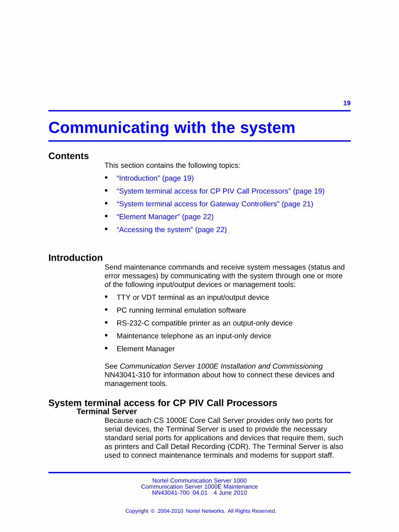
System terminalWhen a system terminal is installed locally, it is typically connected toa serial port on the Terminal Server. This ensures continued access tothe active Call Server. When a system terminal is installed at a remotelocation, a modem and a telephone line are required between the systemterminal and the Terminal Server.
Figure 1 "CS1000E local and remote access system terminals" (page20) shows a typical system terminal configuration to the Call Servers.
Figure 1CS1000E local and remote access system terminals
Nortel Communication Server 1000Communication Server 1000E Maintenance
NN43041-700 04.01 4 June 2010
Copyright © 2004-2010 Nortel Networks. All Rights Reserved.
.
MG 1000E card slot assignment 21
With the CS 1000E, a system terminal can also connect directly to the CallServer, Signaling Server, Media Cards, and Media Gateway 1000T (MG1000T).
When a system terminal is installed directly on the CP PIV Call Processor,it connects to the com 1 port.
When a system terminal connection is made to a CP PM Call Processor,the com (SDI) port is routed through the backplane of the shelf to the 50pin MDF connector. The NTAK19EC cable ships with the CP PM thatadapts the 50 pin MDF to a 25 pin DB connector for connectivity. A 25pin null modem cable is required to adapt the SDI port to a typical PCserial port. Port0 is used for maintenance access. Port1 is for an externalmodem connection.
When a system terminal is installed on the Signaling Server, the rear serialport is the primary port for maintenance and administration.
System terminal access for Gateway ControllersEach Gateway Controller installed in a CS 1000E has 3 serial ports: SDI0,SDI1, and SDI2. SDI2 is not available during system initialization andtherefore cannot be used to access installation menus.
The Gateway Controller serial ports can be used for local debugpurposes or configured as system terminals in LD 17. Unlike the SmallSystem Controller (SSC) SDI ports, all Gateway Controller SDI ports areconfigured through software. The Gateway Controller does not have DIPswitches. Furthermore, the remote SDI feature of the Gateway Controllereliminates the need for a terminal server or TTY on a system with GatewayControllers.
See Communication Server 1000E Installation and Commissioning formore detail about configuring Gateway Controller serial ports.
MG 1000E 10BaseT portThe MG 1000E 10BaseT Ethernet port defaults to the disabled state. Touse the 10BaseT Ethernet port, assign the port a unique IP address, andenable the port from the Call Server. The MG 1000E 10BaseT Ethernetport can run in Normal or Survival mode. In Normal mode, the MG 1000Edoes not provide access to maintenance or alarm management.
MG 1000E card slot assignmentThe MG 1000E contains physical card slots numbered 1 to 10. Whenconfiguring the CS 1000 system, the physical card slot numbers must betransposed to loop, shelf, card.
Nortel Communication Server 1000Communication Server 1000E Maintenance
NN43041-700 04.01 4 June 2010
Copyright © 2004-2010 Nortel Networks. All Rights Reserved.
.
22 Communicating with the system
Connecting to the Media Card RS-232 maintenance portConnect a serial cable either to the rear P2 connector or to the faceplateconnector, but not both. The card’s hardware cannot support two devicesconnected at the same time.
The terminal device should be configured to 9600, 8, N, 1. Configure theflow control to "None" or a similar setting.
If the hardware flow control is enabled, you see information from the cardbut the card does not respond to any keystrokes. If this happens, ensurethe flow control is set to "None", close the session, and reopen it.
Element ManagerElement Manager is a web-based interface that supports a broad range ofsystem management tasks, including:
• configuration and maintenance of IP Peer and IP telephony features
• configuration and maintenance of traditional routes and trunks
• configuration and maintenance of numbering plans
• configuration of Call Server data blocks (such as configuration data,customer data, Common Equipment data, D-channels)
• maintenance commands, system status inquiries, backup and restorefunctions
• software download, patch download, patch activation
The Element Manager web server resides on the Signaling Server and canbe accessed directly through a web browser.
For more information about Element Manager, see Element ManagerSystem Reference – Administration.NN43001-632.
Accessing the systemUse maintenance commands to disable, enable, and test systemcomponents. To perform system maintenance on the CS 1000E, use thefollowing:
• SDI system terminal using command line inputs.
• Element Manager. For details on Element Manager, see ElementManager System Reference – Administration NN43001-632 andSignaling Server IP Line Applications Fundamentals (NN43001-125).
• Maintenance Telephone.
Nortel Communication Server 1000Communication Server 1000E Maintenance
NN43041-700 04.01 4 June 2010
Copyright © 2004-2010 Nortel Networks. All Rights Reserved.
.
Accessing the system 23
Access through an SDI system terminalSend maintenance commands and receive system messages byaccessing the Call Server, through an RS-232 device, such as a VDT orTTY.
On the Call Server, the device can be connected through the TerminalServer or through a Com port. If the RS-232 device is connecteddirectly to the Call Server Com port, a separate terminal is required tocommunicate with each Call Server in the Core.
When you access the system through a system terminal, a login procedureis required. All system passwords are initially set to"0000". Changepasswords in the Configuration Record in LD 17. If a system reload(sysload) occurs before the new password is saved in a data dump, thelast active password remains valid.
Accessing the system from an SDI system terminalTo access the system from an SDI system terminal, follow the steps inProcedure 1 “Accessing the system from an SDI system terminal” (page23).
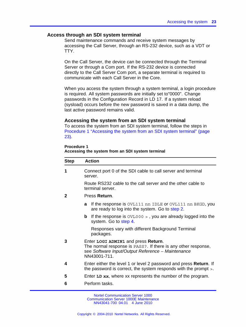
Procedure 1Accessing the system from an SDI system terminal
Step Action
1 Connect port 0 of the SDI cable to call server and terminalserver.
Route RS232 cable to the call server and the other cable toterminal server.
2 Press Return.
a If the response is OVL111 nn IDLE or OVL111 nn BKGD, youare ready to log into the system. Go to step 2.
b If the response is OVL000 > , you are already logged into thesystem. Go to step 4.
Responses vary with different Background Terminalpackages.
3 Enter LOGI ADMIN1 and press Return.The normal response is PASS?. If there is any other response,see Software Input/Output Reference – MaintenanceNN43001-711.
4 Enter either the level 1 or level 2 password and press Return. Ifthe password is correct, the system responds with the prompt >.
5 Enter LD xx, where xx represents the number of the program.
6 Perform tasks.
Nortel Communication Server 1000Communication Server 1000E Maintenance
NN43041-700 04.01 4 June 2010
Copyright © 2004-2010 Nortel Networks. All Rights Reserved.
.
24 Communicating with the system
7 To end the program, enter four asterisks (****).
8 To end the login session, enter LOGO.
--End--
Access through the maintenance telephoneThe Call Server can be accessed using a maintenance telephone. Atelephone functions as a maintenance telephone when the class-of-serviceis defined as Maintenance Telephone Allowed (MTA) in LD 11.
Using a maintenance telephone, you can send a subset of commands.The maintenance telephone takes priority over a system terminal and logsthe terminal out.
Specific commands for testing tones and outpulsing through themaintenance telephone are given in the Tone and Digit Switch andDigitone Receiver Diagnostic (LD 34).
Specific commands for testing trunk connections through the maintenancetelephone are given in the Trunk Diagnostic (LD 36).
The following Maintenance Overlays are accessible from an IP Phoneoperating as a maintenance telephone: 30, 32, 33, 34, 36, 37, 38, 41, 42,43, 45, 46, 60, and 62.
Maintenance Overlay operations are supported on IP Phones exceptfor the Tone and Digit Switch (TDS) commands of LD 34 and TONEcommands of LD 46.
To use the maintenance telephone, the Terminal Number (TN) for thattelephone must be operating.
To access the system using the maintenance telephone, a Special ServicePrefix (SPRE) code, as defined in the Customer Data Block, is entered,followed by "91". See Procedure 2 “Accessing the maintenance telephone”(page 25) for details. To enter commands, press the keys that correspondto the letters and numbers of the command (for example, to enter "LD 42,Return", enter53#42##).
Table 2 "Translation from keyboard to dial pad" (page 25) shows thetranslation from a terminal keyboard to a telephone dial pad.
Nortel Communication Server 1000Communication Server 1000E Maintenance
NN43041-700 04.01 4 June 2010
Copyright © 2004-2010 Nortel Networks. All Rights Reserved.
.
Accessing the system 25
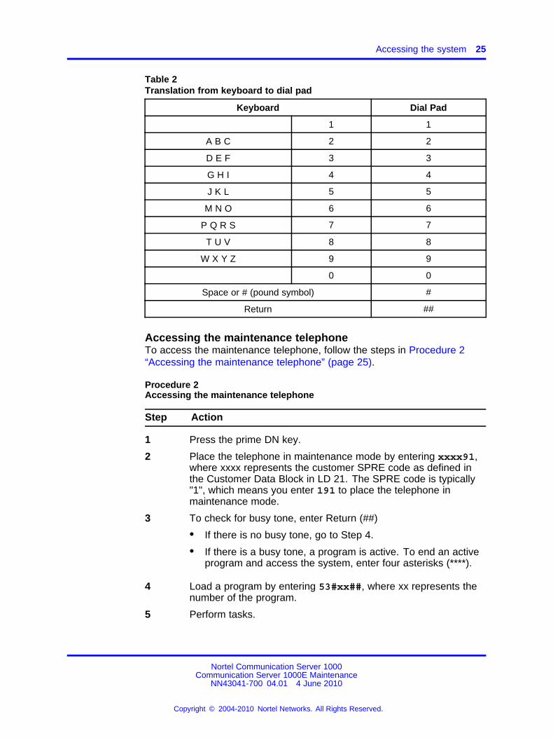
Table 2Translation from keyboard to dial pad
Keyboard Dial Pad
1 1
A B C 2 2
D E F 3 3
G H I 4 4
J K L 5 5
M N O 6 6
P Q R S 7 7
T U V 8 8
W X Y Z 9 9
0 0
Space or # (pound symbol) #
Return ##
Accessing the maintenance telephoneTo access the maintenance telephone, follow the steps in Procedure 2“Accessing the maintenance telephone” (page 25).
Procedure 2Accessing the maintenance telephone
Step Action
1 Press the prime DN key.
2 Place the telephone in maintenance mode by entering xxxx91,where xxxx represents the customer SPRE code as defined inthe Customer Data Block in LD 21. The SPRE code is typically"1", which means you enter 191 to place the telephone inmaintenance mode.
3 To check for busy tone, enter Return (##)
• If there is no busy tone, go to Step 4.
• If there is a busy tone, a program is active. To end an activeprogram and access the system, enter four asterisks (****).
4 Load a program by entering 53#xx##, where xx represents thenumber of the program.
5 Perform tasks.
Nortel Communication Server 1000Communication Server 1000E Maintenance
NN43041-700 04.01 4 June 2010
Copyright © 2004-2010 Nortel Networks. All Rights Reserved.
.
26 Communicating with the system
6 Press the release key to return the telephone to call processingmode. Background routines are then loaded automatically.
--End--
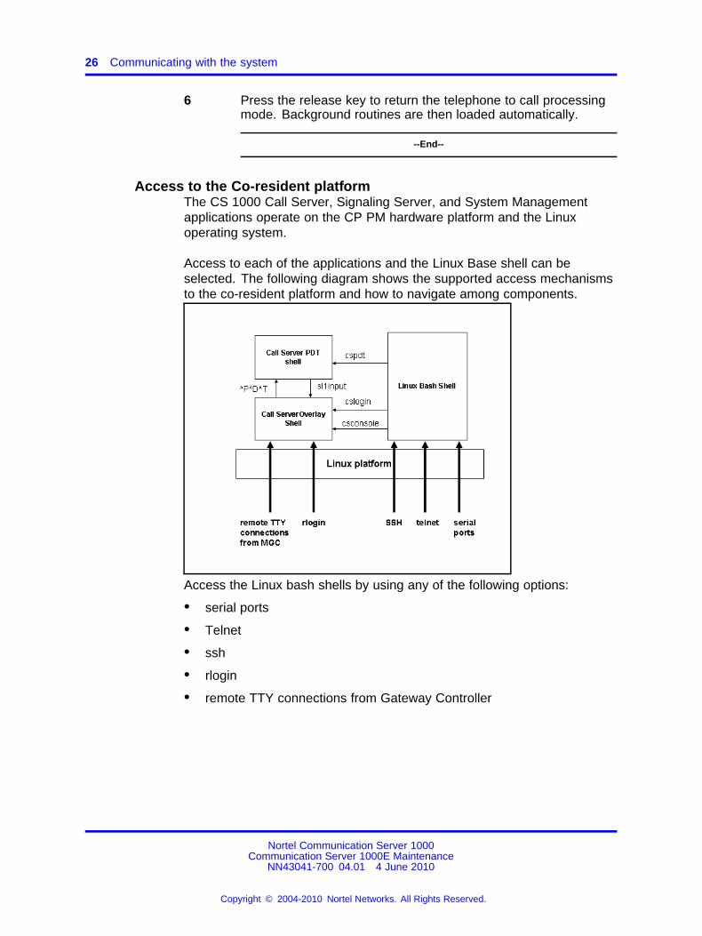
Access to the Co-resident platformThe CS 1000 Call Server, Signaling Server, and System Managementapplications operate on the CP PM hardware platform and the Linuxoperating system.
Access to each of the applications and the Linux Base shell can beselected. The following diagram shows the supported access mechanismsto the co-resident platform and how to navigate among components.
Access the Linux bash shells by using any of the following options:
• serial ports
• Telnet
• ssh
• rlogin
• remote TTY connections from Gateway Controller
Nortel Communication Server 1000Communication Server 1000E Maintenance
NN43041-700 04.01 4 June 2010
Copyright © 2004-2010 Nortel Networks. All Rights Reserved.
.
Accessing the system 27
Serial portsConnecting to the serial ports on CP PM provides access to theLinux base bash shell directly. After logon at the shell and after theauthorization, you can issue Linux base CLI commands and anyappropriate Signaling Server application-related commands. If you chooseto access the Call Server shell, issue the following commands:
• cslogin -- to switch into the Call Server overlay shell.
• cspdt -- to switch into the Call Server PDT shell
• csconsole -- to connect to the CPSI port 0
Co-resident Call Server and Signaling Server shellsCo-res CS and SS supports the following shells:
• Linux Bash shell --The Linux Bash shell is used for Linux Base andSignaling Server applications CLI commands.
• Call Server Overlay shell --The Call Server Overlay shells are usedfor the Call Server overlay commands.
• Call Server PDT shell --The PDT shells are used for the PDTcommands.
Following commands are used to navigate between shells:
Table 3Co-res CS and SS server shells navigation commands
From To Command
Linux Bash Shell Call Server Overlay Shell cslogincsconsole
Linux Bash Shell Call Server PDT shell cspdt
Call Server Overlay Shell Linux Bash Shell CTRL AD
Call Server Overlay Shell Call Server PDT Shell CTRL -PDT
Call Server PDT Shell Call Server Overlay Shell sl1input
Call Server PDT Shell Linux Bash Shell exit
Nortel Communication Server 1000Communication Server 1000E Maintenance
NN43041-700 04.01 4 June 2010
Copyright © 2004-2010 Nortel Networks. All Rights Reserved.
.

28 Communicating with the system
Nortel Communication Server 1000Communication Server 1000E Maintenance
NN43041-700 04.01 4 June 2010
Copyright © 2004-2010 Nortel Networks. All Rights Reserved.
.
29.
Hardware maintenance tools
ContentsThis section contains the following topics:
• “Introduction” (page 29)
• “Alarm/fan module features” (page 29)
• “Compact flash cards” (page 32)
• “Circuit card features” (page 33)
• “Signaling servers for DTLS” (page 52)
• “System alarms” (page 53)
• “Line transfer” (page 54)
• “External power loss” (page 55)
IntroductionFault indicators and hardware features help perform maintenance tasks(particularly identifying and clearing faults). These maintenance toolsinclude:
• circuit card features that include self-tests and status indicators
• LED indicators that identify Call Server power and temperature faults
• system alarms that categorize the severity of component failure
Alarm/fan module featuresThe NTDU64 alarm/fan module provides cooling for a CP PIV CallProcessor. It also provides a thermostat to monitor the Call Servertemperature.
If the Call Server temperature reaches 42�C (107�F), the fan units switchinto high-speed mode. The fans revert to normal speed when the CallServer temperature falls below 37�C (98�F). Also, if one fan fails, theremaining two fans switch into high-speed mode indefinitely.
Nortel Communication Server 1000Communication Server 1000E Maintenance
NN43041-700 04.01 4 June 2010
Copyright © 2004-2010 Nortel Networks. All Rights Reserved.
.
30 Hardware maintenance tools
If the Call Server temperature exceeds 60�C (140�F), it triggers a majoralarm. The Call Server continues to operate, provided it does not losepower.
The CP PM, CP MG, and CP DC cards do not have an alarm/fan module.
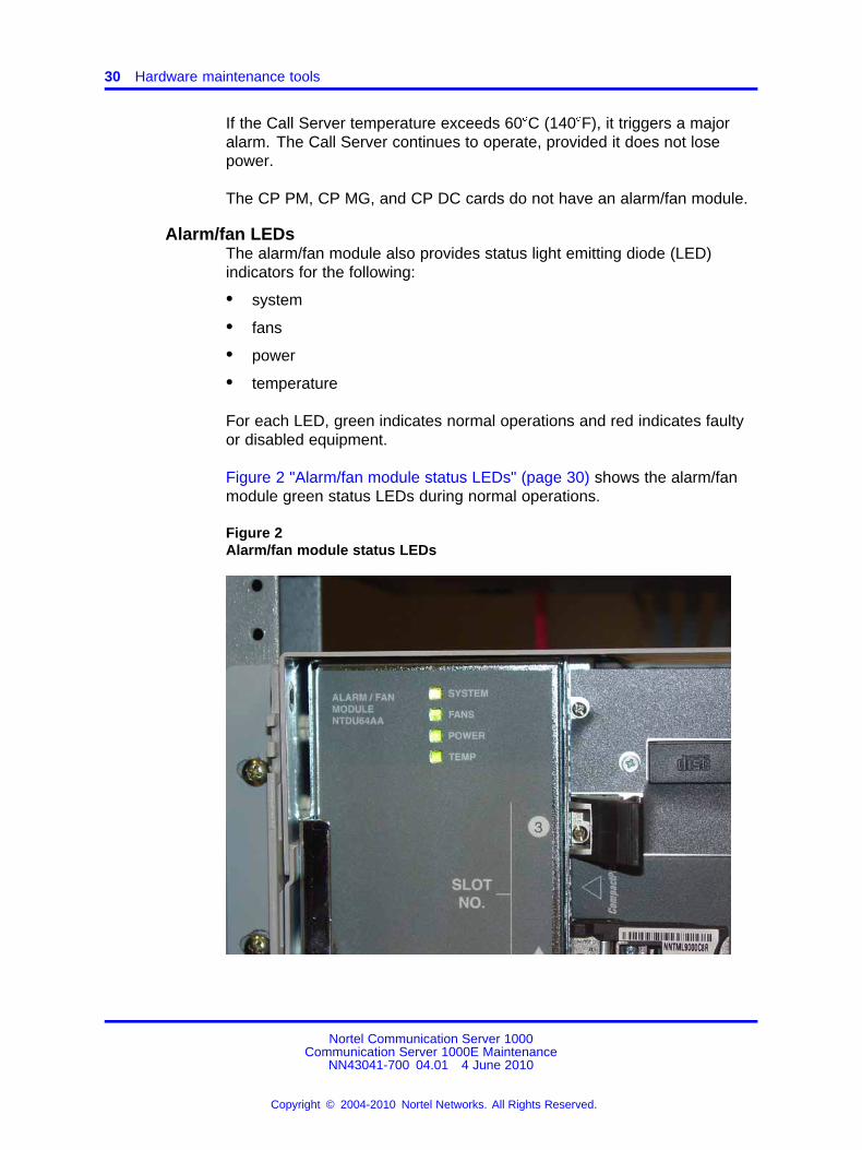
Alarm/fan LEDsThe alarm/fan module also provides status light emitting diode (LED)indicators for the following:
• system
• fans
• power
• temperature
For each LED, green indicates normal operations and red indicates faultyor disabled equipment.
Figure 2 "Alarm/fan module status LEDs" (page 30) shows the alarm/fanmodule green status LEDs during normal operations.
Figure 2Alarm/fan module status LEDs
Nortel Communication Server 1000Communication Server 1000E Maintenance
NN43041-700 04.01 4 June 2010
Copyright © 2004-2010 Nortel Networks. All Rights Reserved.
.
Alarm/fan module features 31
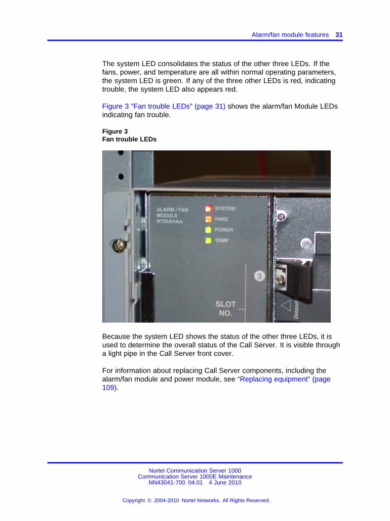
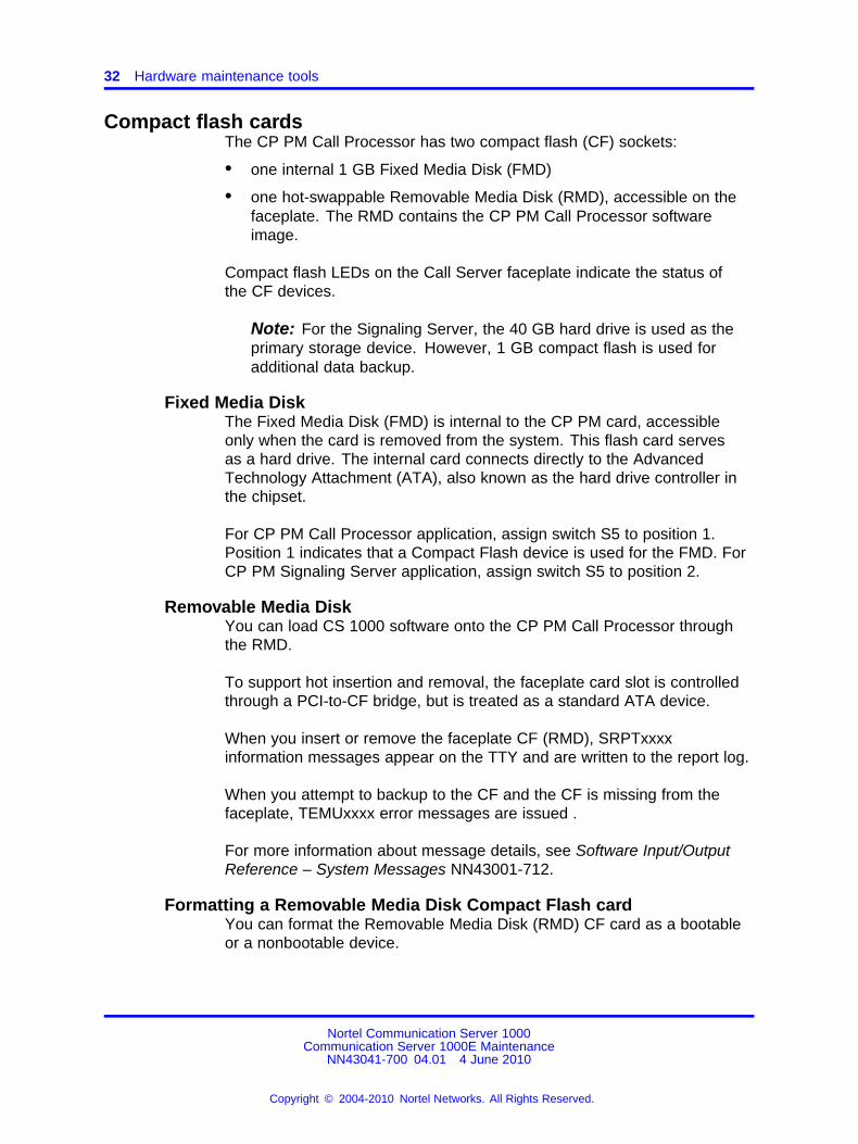
The system LED consolidates the status of the other three LEDs. If thefans, power, and temperature are all within normal operating parameters,the system LED is green. If any of the three other LEDs is red, indicatingtrouble, the system LED also appears red.
Figure 3 "Fan trouble LEDs" (page 31) shows the alarm/fan Module LEDsindicating fan trouble.
Figure 3Fan trouble LEDs
Because the system LED shows the status of the other three LEDs, it isused to determine the overall status of the Call Server. It is visible througha light pipe in the Call Server front cover.
For information about replacing Call Server components, including thealarm/fan module and power module, see “Replacing equipment” (page109).
Nortel Communication Server 1000Communication Server 1000E Maintenance
NN43041-700 04.01 4 June 2010
Copyright © 2004-2010 Nortel Networks. All Rights Reserved.
.
32 Hardware maintenance tools
Compact flash cardsThe CP PM Call Processor has two compact flash (CF) sockets:
• one internal 1 GB Fixed Media Disk (FMD)
• one hot-swappable Removable Media Disk (RMD), accessible on thefaceplate. The RMD contains the CP PM Call Processor softwareimage.
Compact flash LEDs on the Call Server faceplate indicate the status ofthe CF devices.
Note: For the Signaling Server, the 40 GB hard drive is used as theprimary storage device. However, 1 GB compact flash is used foradditional data backup.
Fixed Media DiskThe Fixed Media Disk (FMD) is internal to the CP PM card, accessibleonly when the card is removed from the system. This flash card servesas a hard drive. The internal card connects directly to the AdvancedTechnology Attachment (ATA), also known as the hard drive controller inthe chipset.
For CP PM Call Processor application, assign switch S5 to position 1.Position 1 indicates that a Compact Flash device is used for the FMD. ForCP PM Signaling Server application, assign switch S5 to position 2.
Removable Media DiskYou can load CS 1000 software onto the CP PM Call Processor throughthe RMD.
To support hot insertion and removal, the faceplate card slot is controlledthrough a PCI-to-CF bridge, but is treated as a standard ATA device.
When you insert or remove the faceplate CF (RMD), SRPTxxxxinformation messages appear on the TTY and are written to the report log.
When you attempt to backup to the CF and the CF is missing from thefaceplate, TEMUxxxx error messages are issued .
For more information about message details, see Software Input/OutputReference – System Messages NN43001-712.
Formatting a Removable Media Disk Compact Flash cardYou can format the Removable Media Disk (RMD) CF card as a bootableor a nonbootable device.
Nortel Communication Server 1000Communication Server 1000E Maintenance
NN43041-700 04.01 4 June 2010
Copyright © 2004-2010 Nortel Networks. All Rights Reserved.
.
Circuit card features 33
From PDT1 or PDT2, issue the format command as follows: formatCf2{0,1}.
where
0 = a nonbootable device1 = a bootable device
You can format a compact flash on a PC (Microsoft Windows 98SE,Microsoft Windows 2000, or Microsoft Windows XP) for use as a compactflash in the RMD. You format the disk in FAT16 - DOS format.
Circuit card featuresCircuit card features describes various circuit cards and features.
Self-testsA self-test checks to see that a card is working correctly. Many cardsperform a self-test on power-up. The software commands Disable andEnable force a card to self-test. The results of a self-test generally showwhether or not there is a problem with the card.
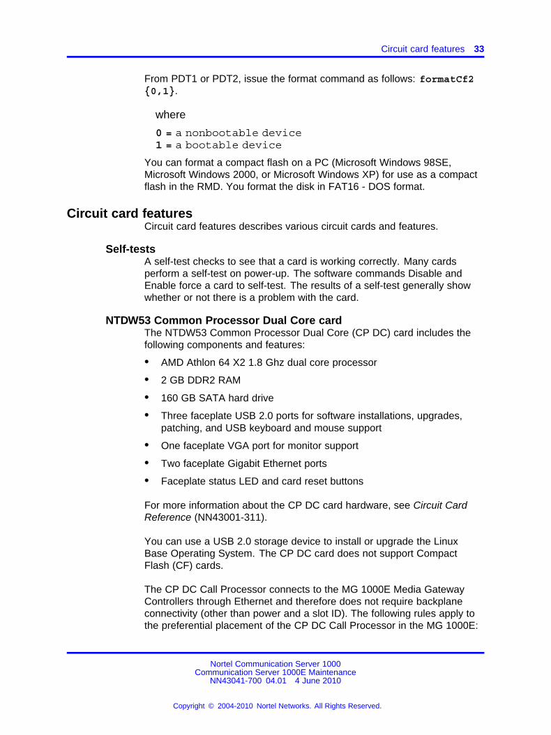
NTDW53 Common Processor Dual Core cardThe NTDW53 Common Processor Dual Core (CP DC) card includes thefollowing components and features:
• AMD Athlon 64 X2 1.8 Ghz dual core processor
• 2 GB DDR2 RAM
• 160 GB SATA hard drive
• Three faceplate USB 2.0 ports for software installations, upgrades,patching, and USB keyboard and mouse support
• One faceplate VGA port for monitor support
• Two faceplate Gigabit Ethernet ports
• Faceplate status LED and card reset buttons
For more information about the CP DC card hardware, see Circuit CardReference (NN43001-311).
You can use a USB 2.0 storage device to install or upgrade the LinuxBase Operating System. The CP DC card does not support CompactFlash (CF) cards.
The CP DC Call Processor connects to the MG 1000E Media GatewayControllers through Ethernet and therefore does not require backplaneconnectivity (other than power and a slot ID). The following rules apply tothe preferential placement of the CP DC Call Processor in the MG 1000E:
Nortel Communication Server 1000Communication Server 1000E Maintenance
NN43041-700 04.01 4 June 2010
Copyright © 2004-2010 Nortel Networks. All Rights Reserved.
.
34 Hardware maintenance tools
• Do not install the CP DC Call Processor in slot 0 of any MediaGateway. This slot is reserved for the Gateway Controller.
• For ease of cabling, place the CP DC Call processor in slot 1 (slot 22or 23 for MG 1010), next to the Gateway Controller.
CP DC faceplateThe CP DC card faceplate provides a reset button, status LEDs, threeUSB 2.0 ports, one VGA port, and two Gigabit Ethernet ports. TheNTDW53 CP DC card faceplate is shown in Figure 4 "NTDW53 CP DCfaceplate" (page 34).
Figure 4NTDW53 CP DC faceplate
The VGA port provides monitor support. The three USB 2.0 ports provideUSB keyboard, USB mouse, and USB 2.0 storage device support. Youcan use the USB 2.0 ports for software installations, upgrades, andpatches.
The reset button provides a CP DC hardware reset. The reset button isrecessed to prevent accidental resets. You must use a small blunt objectto access the reset button. During a reset the status LED will flash red untilthe reset is complete. The CP DC card does not provide a faceplate INIbutton. To re-initialize a CP DC card, use the Command Line Interface(CLI) appstart cs restartcommand.
Status LEDThe CP DC faceplate STS LED is a tri-color system status indicator. Todetermine the CP DC system status, see Table 4 "CP DC faceplate statusLED" (page 34).
Table 4CP DC faceplate status LED
LED color CP DC system status
Green Link is up
Flashing Green Link is down
Orange Linux applications loading
Flashing Orange Linux applications load successful
Red BIOS self test
Nortel Communication Server 1000Communication Server 1000E Maintenance
NN43041-700 04.01 4 June 2010
Copyright © 2004-2010 Nortel Networks. All Rights Reserved.
.
Circuit card features 35
LED color CP DC system status
Flashing Red Bootrom and Linux base loading
Off No power
The CP DC faceplate RED LED is not active and is intended for future useThe RED LED is a tri-color redundancy status indicator.
The HD ACT LED flashes during SATA hard drive activity.
CP DC serial data interface portsThe CP DC has two serial data interface (SDI) ports: Port 0 and Port 1.Both ports are standard RS232 DTE ports. They are routed through thebackplane of the shelf to a 50-pin main distribution frame (MDF) connectoron the back of the shelf. You require a NTAK19ECE6 cable to adapt the50-pin MDF to a pair of 25-pin DB connectors. A 25-pin null modem isrequired to adapt an SDI port to a typical PC serial port. Port 0 is used formaintenance access. Port 1 is for an external modem connection.
You can change the baud rate of the CP DC card from the BIOS menu.The default serial connection baud rate of the CP DC card is 9600 bps,no parity, 1 stop bit.
The CP DC card serial port connection procedure remains the same asthe CP PM card . For more information, see Linux Platform Base andApplications installation and commissioning (NN43001-315) .
CP DC media storageThe CP DC card contains a 160 GB SATA hard drive. The hard drivestores the Linux Base Operating System. If the hard drive fails, you canreplace it by performing the CP DC hard drive replacement procedure, seeCircuit Card Reference (NN43001-311).
NTDW61 Common Processor Pentium Mobile cardNTDW61 Common Processor Pentium Mobile (CP PM) card featuresinclude the following:
• Intel Pentium M 738 1.4 GHz
• two compact flash (CF) sockets
— one internal 1 GB Fixed Media Disk (FMD)
— one hot-swappable Removable Media Disk (RMD), accessible onthe faceplate.
• 1 GB of DDR RAM, expandable to 2 GB
• two 100BaseT Ethernet ports
Nortel Communication Server 1000Communication Server 1000E Maintenance
NN43041-700 04.01 4 June 2010
Copyright © 2004-2010 Nortel Networks. All Rights Reserved.
.
36 Hardware maintenance tools
— LAN 0 used for ELAN
— LAN 1 not used on Call Server
• one 1 Gbps Ethernet port for HSP
• two SDI ports
• one USB port
• a reset (RST) button to cold start the Call Server
• an initialize (INI) button to warm start the Call Server
• an Active CPU or Call Server Redundancy (CS RED) LED
The CP PM Call Processor connects to the MG 1000E Media GatewayControllers through Ethernet and therefore does not require backplaneconnectivity (other than power and a slot ID). The following rules apply tothe preferential placement of the CP PM Call Processor in the MG 1000E:
• Do not install the CP PM Call Processor in slot 0 of any MediaGateway. This slot is reserved for the Gateway Controller.
• For ease of cabling, place the CP PM Call processor in slot 1 (slot 22or 23 for MG 1010), next to the Gateway Controller.
• In a system configured for Campus Redundancy, place the two CP PMCall Processors in separate MG 1000E cabinets to increase potentialsurvivability.
The CP PM has no power (PWR) LED.
The CP PM architecture has no system utility (Sys Util) card, so thedisplay usually associated with the Sys Util card is not present.
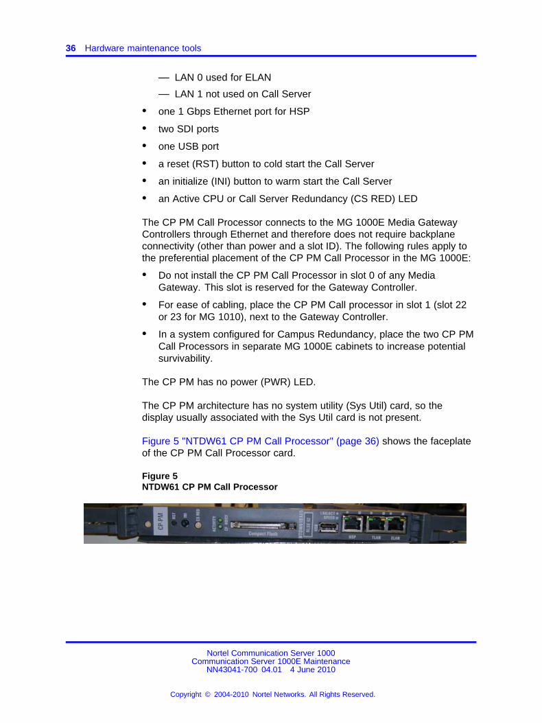
Figure 5 "NTDW61 CP PM Call Processor" (page 36) shows the faceplateof the CP PM Call Processor card.
Figure 5NTDW61 CP PM Call Processor
Nortel Communication Server 1000Communication Server 1000E Maintenance
NN43041-700 04.01 4 June 2010
Copyright © 2004-2010 Nortel Networks. All Rights Reserved.
.
Circuit card features 37
Initialize buttonThe manual initialize (Init) button associated with the active Call Serverstarts the Initialize program. The Initialize program can clear someequipment faults. It then rebuilds call-dependent data and generatessystem messages indicating the status of the system. This process iscalled an initialization.
CAUTIONSERVICE INTERRUPTIONCall processing is briefly interrupted during an initialization.
Reset buttonYou can cold restart the processor card with the Reset button. This isequivalent to a full power start up of the processor card. The SystemLoader initiates call processing and starts memory-checking diagnostics.This process is called a system reload or sysload.
CAUTIONSERVICE INTERRUPTIONDuring a sysload, active calls are disconnected and the systemgoes into an emergency line transfer state. Use the reset buttononly when specifically instructed to do so in an NTP.
CP PM Call Processor faceplate LEDsThe status LED indications of the NTDW61 CP PM Call Processor are asfollows:
• Off: no power
• Red: BIOS self-test running
• Flashing red: bootrom and Operating System (OS) loading
• Yellow: sysload phase 1
• Flashing yellow: sysload phase 2
• Flashing green: SL1 loading on active core
• Green: normal operation
The Active CPU LED indications are as follows:
• Off: no power
• Green: redundant mode, active
• Flashing green: split mode, active
• Yellow: redundant mode, standby
Nortel Communication Server 1000Communication Server 1000E Maintenance
NN43041-700 04.01 4 June 2010
Copyright © 2004-2010 Nortel Networks. All Rights Reserved.
.
38 Hardware maintenance tools
• Flashing yellow: split mode, standby
• Red: single mode
The ELAN LED indications are as follows:
• LED1 Off: 10 Mbps
• LED1 Yellow: 100 Mbps
• LED2 Off: no link, no activity
• LED2 Green: link valid
• LED2 Blink: link valid and activity
The HSP LED indications are as follows:
• LED1 Off: 10 Mbps
• LED1 Yellow: 100 Mbps
• LED1 Green: 1000 Mbps
• LED2 Off: no link, no activity
• LED2 Green: link valid
• LED2 Blink: link valid and activity
NTDW61 CP PM Signaling ServerNTDW61 CP PM Signaling Server card features includes the following:
• Intel Pentium M 738 1.4 GHz processor
• one hard disk drive
• two compact flash (CF) sockets
— one internal 1 GB Fixed Media Disk (FMD)
— one hot-swappable Removable Media Disk (RMD), which isaccessible on the faceplate.
• 1 GB of DDR RAM, expandable to 2 GB
• two 100BaseT Ethernet ports
— LAN 0 used for ELAN
— LAN 1 used for TLAN
• one 1 Gbps Ethernet port (not used on Signaling Server)
• two serial ports
• one USB port (not used on Signaling Server)
Nortel Communication Server 1000Communication Server 1000E Maintenance
NN43041-700 04.01 4 June 2010
Copyright © 2004-2010 Nortel Networks. All Rights Reserved.
.
Circuit card features 39
• a reset (RST) button to cold start the Signaling Server
• an initialize (INI) button to warm start the Signaling Server
CP PM Signaling Server LEDsThe status LED indications of the NTDW61 CP PM Signaling Server areas follows:
• Off: no power
• Red: BIOS self-test running
• Flashing red: bootrom and operating system (OS) loading
• Yellow: applications loading
• Flashing yellow: applications loaded successfully
• Green: pbxLink up
• Flashing green: pbxLink down
For more detailed information about the CP PM Signaling Server, seeSignaling Server IP Line Applications Fundamentals (NN43001-125).
NT4N39 PIV Call Processor featuresButtons on the NT4N39 PIV Call processor cards allow the administrator toinitialize and reset the system.
Initialize buttonThe manual initialize (Init) button associated with the active Call Serverstarts the Initialize program. The Initialize program can clear someequipment faults. It then rebuilds call-dependent data and generatessystem messages indicating the status of the system. This process iscalled an initialization.
CAUTIONSERVICE INTERRUPTIONCall processing is briefly interrupted during an initialization.
Reset buttonYou can cold restart the processor card with the Reset button. This isequivalent to a full power start up of the processor card. The SystemLoader initiates call processing and starts memory-checking diagnostics.This process is called a system reload or sysload.
Nortel Communication Server 1000Communication Server 1000E Maintenance
NN43041-700 04.01 4 June 2010
Copyright © 2004-2010 Nortel Networks. All Rights Reserved.
.
40 Hardware maintenance tools
CAUTIONSERVICE INTERRUPTIONDuring a sysload, active calls are disconnected and the systemgoes into an emergency line transfer state. Use the reset buttononly when specifically instructed to do so in an NTP.
CP PIV faceplate LEDsThe CP PIV faceplate features the following 5 LEDs:
• PWR – Solid Green – Power Good
• CF – Flashing Green shows activity on compact flash cards CF1 orCF2.
• HDD – Flashing Green shows activity on secondary IDE bus (not used)
• LAN1 – ELAN Activity
• LAN2 – HSP Activity
— Flashing Yellow – 10 MB
— Flashing Green – 100 MB
— Flashing Amber – 1000 MB (1 GB)
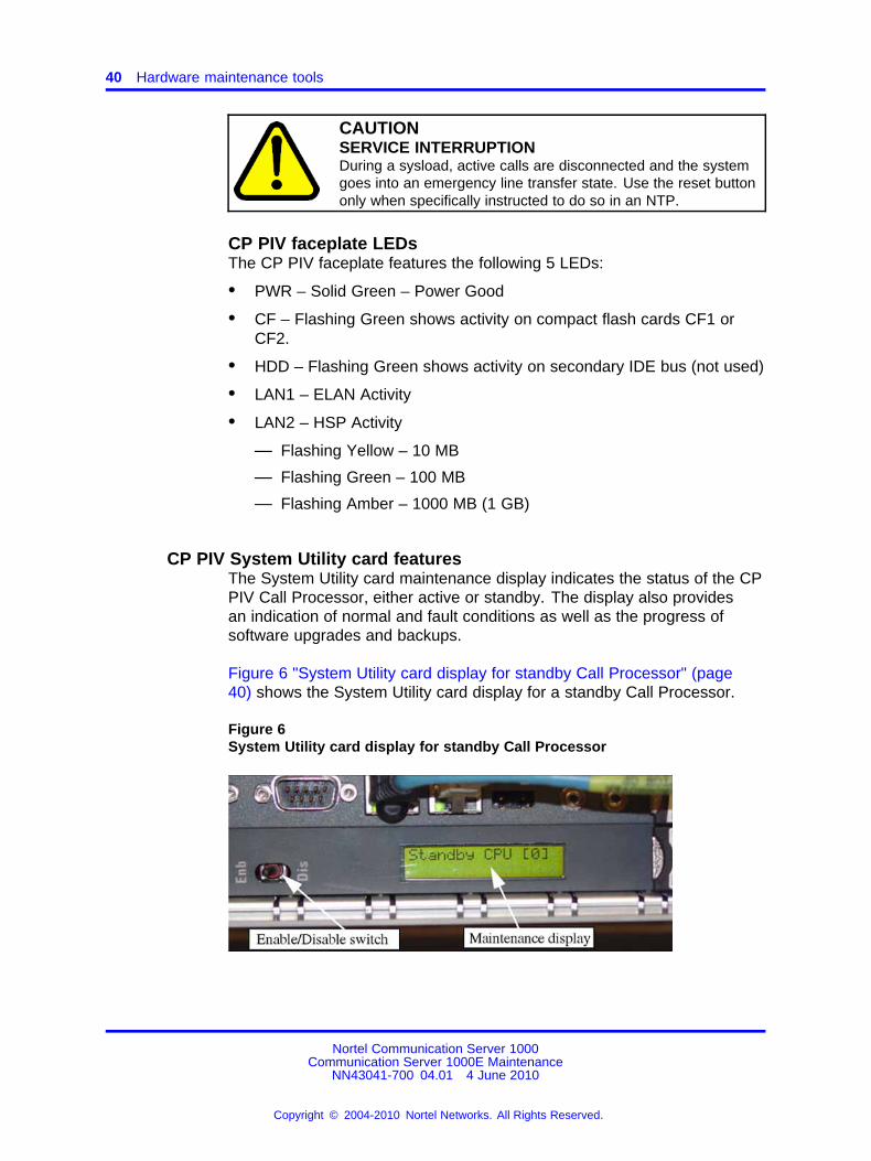
CP PIV System Utility card featuresThe System Utility card maintenance display indicates the status of the CPPIV Call Processor, either active or standby. The display also providesan indication of normal and fault conditions as well as the progress ofsoftware upgrades and backups.
Figure 6 "System Utility card display for standby Call Processor" (page40) shows the System Utility card display for a standby Call Processor.
Figure 6System Utility card display for standby Call Processor
Nortel Communication Server 1000Communication Server 1000E Maintenance
NN43041-700 04.01 4 June 2010
Copyright © 2004-2010 Nortel Networks. All Rights Reserved.
.
Circuit card features 41
Interpretations of the maintenance display codes are listed in the SoftwareInput/Output Reference – System Messages NN43001-712. Examineprevious codes, system messages, and visual indicators with any currentmaintenance display codes to properly analyze faults.
Each new code shown on a maintenance display overwrites the one beforeit. However, all codes displayed are recorded. You can review them byprinting the History File (in LD 22).
Figure 6 "System Utility card display for standby Call Processor" (page40) also shows the location of the Enable/Disable (Enb/Dis) switch on thecard. This switch enables and disables the hardware for that card.
Table 5Core module ID switch settings (System Utility card)
Position 1 Position 2
Core 0 On On
Core 1 Off On
The System Utility card also contains DIP switches that specify theaddress of the card for Call Server 0 or Call Server 1. The Core IDswitches are set in the factory.
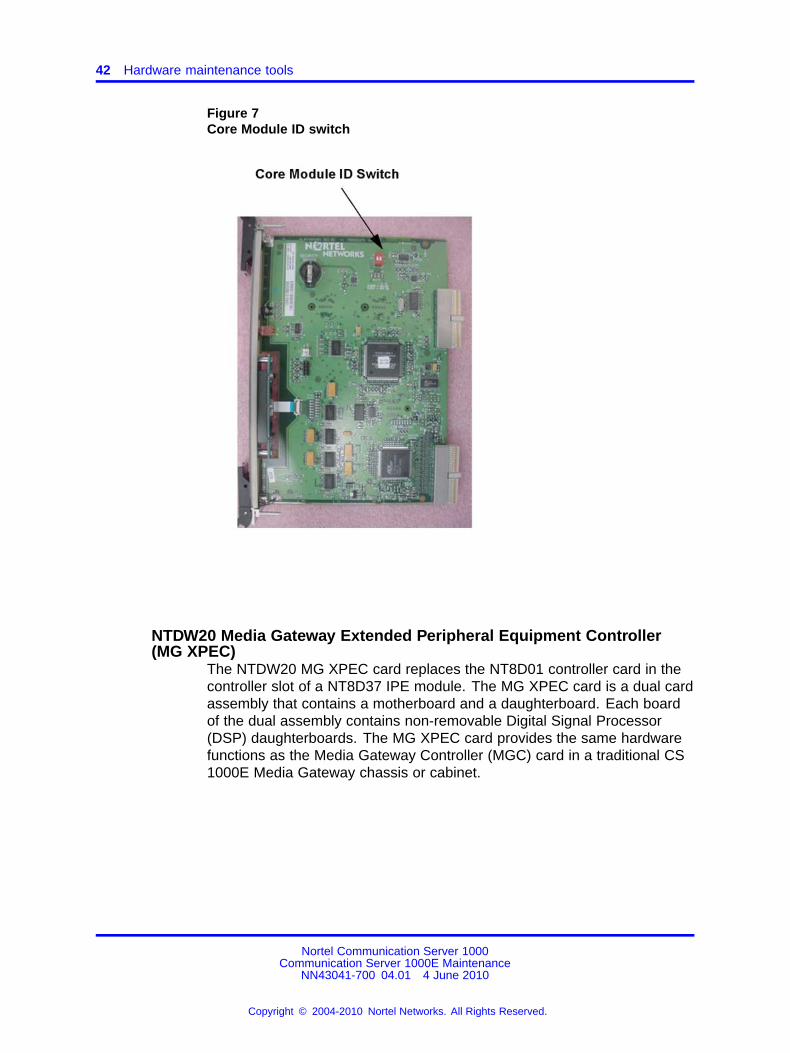
Confirm that these settings match the identification labels for the moduleinto which they will be installed. See Table 5 "Core module ID switchsettings (System Utility card)" (page 41) and Figure 7 "Core Module IDswitch" (page 42).
Nortel Communication Server 1000Communication Server 1000E Maintenance
NN43041-700 04.01 4 June 2010
Copyright © 2004-2010 Nortel Networks. All Rights Reserved.
.
42 Hardware maintenance tools
Figure 7Core Module ID switch
NTDW20 Media Gateway Extended Peripheral Equipment Controller(MG XPEC)
The NTDW20 MG XPEC card replaces the NT8D01 controller card in thecontroller slot of a NT8D37 IPE module. The MG XPEC card is a dual cardassembly that contains a motherboard and a daughterboard. Each boardof the dual assembly contains non-removable Digital Signal Processor(DSP) daughterboards. The MG XPEC card provides the same hardwarefunctions as the Media Gateway Controller (MGC) card in a traditional CS1000E Media Gateway chassis or cabinet.
Nortel Communication Server 1000Communication Server 1000E Maintenance
NN43041-700 04.01 4 June 2010
Copyright © 2004-2010 Nortel Networks. All Rights Reserved.
.
Circuit card features 43
NTDW56 and NTDW59 Common Processor Media Gateway cardThe Common Processor Media Gateway (CP MG) card functions as agateway controller with DSP resources for IP Media Gateways in a CS1000E system, and functions as a Co-resident Call Server and SignalingServer. The CP MG card occupies slot 0 in a Media Gateway. The CPMG card is available in two versions:
• NTDW56 - CP MG with 32 DSP ports
• NTDW59 - CP MG with 128 DSP ports
The Gateway Controller portion of the CP MG card is based on the samearchitecture as the Media Gateway Controller (MGC) card. For moreinformation, see “NTDW60 Media Gateway Controller card” (page 43).The CP MG card contains non-removable DSP resources. MGC DSPdaughterboards are not required for CP MG cards.
The Server portion of the CP MG card is based on the same architectureas the Common Processor Pentium Mobile (CP PM) card. For moreinformation, see “NTDW61 Common Processor Pentium Mobile card”(page 35).
NTDW60 Media Gateway Controller cardThe NTDW60 Media Gateway Controller (MGC) card provides a gatewaycontroller for MG 1000E IP Media Gateways in a CS 1000E system. TheMGC card functions as a gateway controller for CS 1000E Call Servers.
The MGC card has two expansion sites to accommodate Digital SignalProcessor (DSP) daughterboards. The MGC card occupies slot 0 in aMedia Gateway.
Excluding DSP daughterboards, MGC card features include:
• internal compact flash, which appears to the software as a standardhard disk drive
• six 100BaseT Ethernet ports
• three SDI ports
• four-character LED display
NTDW60 Media Gateway Controller LEDsThe Media Gateway Controller faceplate provides a 4-character LEDdisplay that indicates normal or abnormal situations during systeminitialization and regular operation of the MGC.
Nortel Communication Server 1000Communication Server 1000E Maintenance
NN43041-700 04.01 4 June 2010
Copyright © 2004-2010 Nortel Networks. All Rights Reserved.
.
44 Hardware maintenance tools
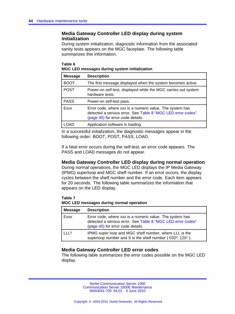
Media Gateway Controller LED display during systeminitializationDuring system initialization, diagnostic information from the associatedsanity tests appears on the MGC faceplate. The following tablesummarizes this information.
Table 6MGC LED messages during system initialization
Message Description
BOOT The first message displayed when the system becomes active.
POST Power-on self-test, displayed while the MGC carries out systemhardware tests.
PASS Power-on self-test pass.
Exxx Error code, where xxx is a numeric value. The system hasdetected a serious error. See Table 8 "MGC LED error codes"(page 45) for error code details.
LOAD Application software is loading.
In a successful initialization, the diagnostic messages appear in thefollowing order: BOOT, POST, PASS, LOAD.
If a fatal error occurs during the self-test, an error code appears. ThePASS and LOAD messages do not appear.
Media Gateway Controller LED display during normal operationDuring normal operations, the MGC LED displays the IP Media Gateway(IPMG) superloop and MGC shelf number. If an error occurs, the displaycycles between the shelf number and the error code. Each item appearsfor 20 seconds. The following table summarizes the information thatappears on the LED display.
Table 7MGC LED messages during normal operation
Message Description
Exxx Error code, where xxx is a numeric value. The system hasdetected a serious error. See Table 8 "MGC LED error codes"(page 45) for error code details.
LLLS IPMG super loop and MGC shelf number, where LLL is thesuperloop number and S is the shelf number ( 0320, 1201 ).
Media Gateway Controller LED error codesThe following table summarizes the error codes possible on the MGC LEDdisplay.
Nortel Communication Server 1000Communication Server 1000E Maintenance
NN43041-700 04.01 4 June 2010
Copyright © 2004-2010 Nortel Networks. All Rights Reserved.
.
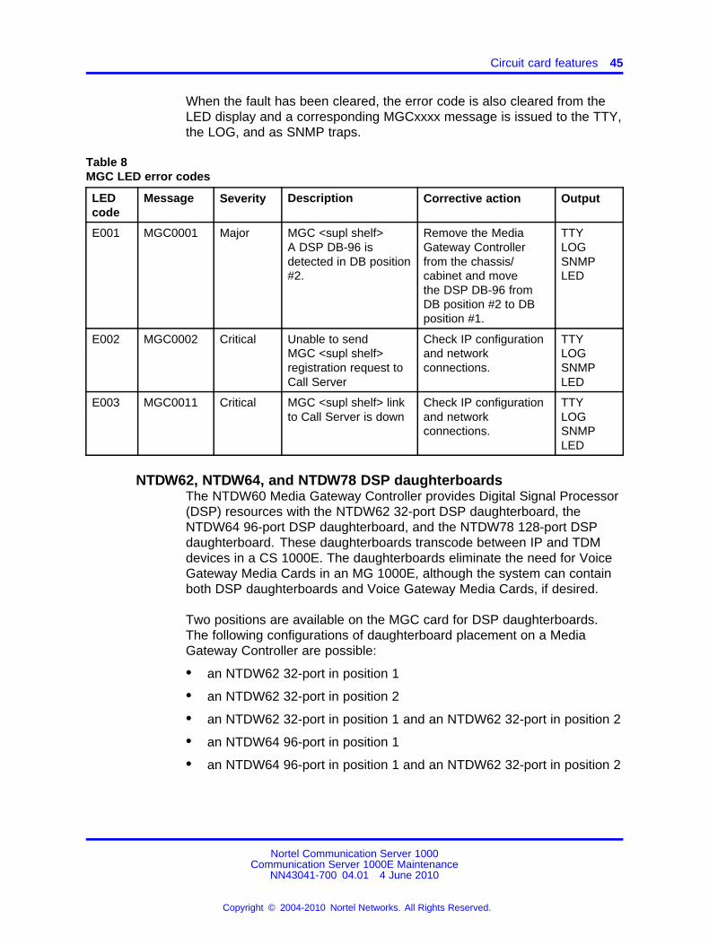
Circuit card features 45
When the fault has been cleared, the error code is also cleared from theLED display and a corresponding MGCxxxx message is issued to the TTY,the LOG, and as SNMP traps.
Table 8MGC LED error codes
LEDcode
Message Severity Description Corrective action Output
E001 MGC0001 Major MGC <supl shelf>A DSP DB-96 isdetected in DB position#2.
Remove the MediaGateway Controllerfrom the chassis/cabinet and movethe DSP DB-96 fromDB position #2 to DBposition #1.
TTYLOGSNMPLED
E002 MGC0002 Critical Unable to sendMGC <supl shelf>registration request toCall Server
Check IP configurationand networkconnections.
TTYLOGSNMPLED
E003 MGC0011 Critical MGC <supl shelf> linkto Call Server is down
Check IP configurationand networkconnections.
TTYLOGSNMPLED
NTDW62, NTDW64, and NTDW78 DSP daughterboardsThe NTDW60 Media Gateway Controller provides Digital Signal Processor(DSP) resources with the NTDW62 32-port DSP daughterboard, theNTDW64 96-port DSP daughterboard, and the NTDW78 128-port DSPdaughterboard. These daughterboards transcode between IP and TDMdevices in a CS 1000E. The daughterboards eliminate the need for VoiceGateway Media Cards in an MG 1000E, although the system can containboth DSP daughterboards and Voice Gateway Media Cards, if desired.
Two positions are available on the MGC card for DSP daughterboards.The following configurations of daughterboard placement on a MediaGateway Controller are possible:
• an NTDW62 32-port in position 1
• an NTDW62 32-port in position 2
• an NTDW62 32-port in position 1 and an NTDW62 32-port in position 2
• an NTDW64 96-port in position 1
• an NTDW64 96-port in position 1 and an NTDW62 32-port in position 2
Nortel Communication Server 1000Communication Server 1000E Maintenance
NN43041-700 04.01 4 June 2010
Copyright © 2004-2010 Nortel Networks. All Rights Reserved.
.
46 Hardware maintenance tools
• an NTDW78 128-port in position 1
• an NTDW78 128-port in position 1 and an NTDW78 128-port inposition 2
Note: MGC cards provisioned with greater than 196 DSP ports areonly supported in High Density Primary Rate Interface Media Gateways(HD PRI Gateway).
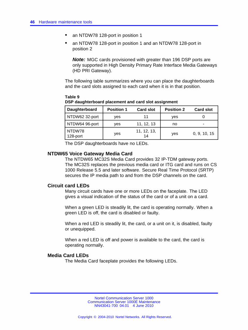
The following table summarizes where you can place the daughterboardsand the card slots assigned to each card when it is in that position.
Table 9DSP daughterboard placement and card slot assignment
Daughterboard Position 1 Card slot Position 2 Card slot
NTDW62 32-port yes 11 yes 0
NTDW64 96-port yes 11, 12, 13 no -
NTDW78128-port
yes11, 12, 13,
14yes 0, 9, 10, 15
The DSP daughterboards have no LEDs.
NTDW65 Voice Gateway Media CardThe NTDW65 MC32S Media Card provides 32 IP-TDM gateway ports.The MC32S replaces the previous media card or ITG card and runs on CS1000 Release 5.5 and later software. Secure Real Time Protocol (SRTP)secures the IP media path to and from the DSP channels on the card.
Circuit card LEDsMany circuit cards have one or more LEDs on the faceplate. The LEDgives a visual indication of the status of the card or of a unit on a card.
When a green LED is steadily lit, the card is operating normally. When agreen LED is off, the card is disabled or faulty.
When a red LED is steadily lit, the card, or a unit on it, is disabled, faultyor unequipped.
When a red LED is off and power is available to the card, the card isoperating normally.
Media Card LEDsThe Media Card faceplate provides the following LEDs.
Nortel Communication Server 1000Communication Server 1000E Maintenance
NN43041-700 04.01 4 June 2010
Copyright © 2004-2010 Nortel Networks. All Rights Reserved.
.
Circuit card features 47
Status LEDThe Media Card faceplate red LED indicates the following:
• the enabled/disabled status of the card
• the self-testing result during power up or card insertion into anoperational system
Ethernet activity LEDsThe Media Card faceplate contains Ethernet activity LEDs for each subnet.The faceplate contains six Ethernet activity LEDs, three for the ELANsubnet and three for the TLAN subnet. The LEDs indicate the followinglinks on the ELAN and TLAN subnets (in order from the top):
• 100 (100BaseT)
• 10 (10BaseT)
• A (Activity)
Maintenance hex displayThe four-digit LED-based hexadecimal display provides the status of theMedia Card at all times. The hex display provides an indication of faultconditions and the progress of PC Card-based software upgrades orbackups. See Table 36 "Media Card faceplate maintenance display codes"(page 162) for a description of the hex display codes.
The Maintenance display also indicates the progress of the internalself-test in the form of T:xx.
ITG-P LED (Card Status)The red status faceplate LED indicates the enabled or disabled statusof the 24 card ports. The LED is on (red) during the power-up or resetsequence. The LED remains lit until the system enables the card. If theLED remains on, the self-test failed, the card is disabled, or the cardrebooted.
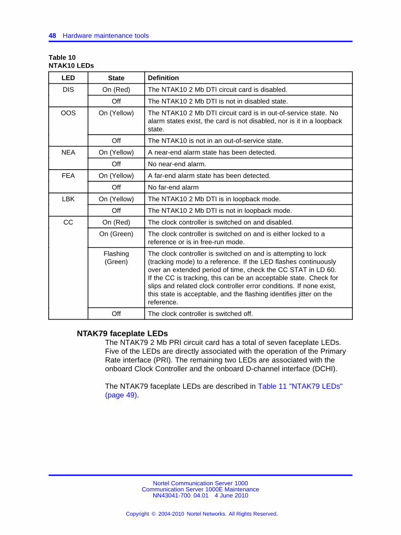
NTAK10 faceplate LEDsThe NTAK10 2 Mb DTI circuit card has a total of six faceplate LEDs. Fiveof the LEDs are directly associated with the operation of the NTAK10circuit card. The remaining LED is associated with the onboard clockcontroller.
The following table describes the NTAK10 LEDs.
Nortel Communication Server 1000Communication Server 1000E Maintenance
NN43041-700 04.01 4 June 2010
Copyright © 2004-2010 Nortel Networks. All Rights Reserved.
.
48 Hardware maintenance tools
Table 10NTAK10 LEDs
LED State Definition
On (Red) The NTAK10 2 Mb DTI circuit card is disabled.DIS
Off The NTAK10 2 Mb DTI is not in disabled state.
On (Yellow) The NTAK10 2 Mb DTI circuit card is in out-of-service state. Noalarm states exist, the card is not disabled, nor is it in a loopbackstate.
OOS
Off The NTAK10 is not in an out-of-service state.
On (Yellow) A near-end alarm state has been detected.NEA
Off No near-end alarm.
On (Yellow) A far-end alarm state has been detected.FEA
Off No far-end alarm
On (Yellow) The NTAK10 2 Mb DTI is in loopback mode.LBK
Off The NTAK10 2 Mb DTI is not in loopback mode.
On (Red) The clock controller is switched on and disabled.
On (Green) The clock controller is switched on and is either locked to areference or is in free-run mode.
Flashing(Green)
The clock controller is switched on and is attempting to lock(tracking mode) to a reference. If the LED flashes continuouslyover an extended period of time, check the CC STAT in LD 60.If the CC is tracking, this can be an acceptable state. Check forslips and related clock controller error conditions. If none exist,this state is acceptable, and the flashing identifies jitter on thereference.
CC
Off The clock controller is switched off.
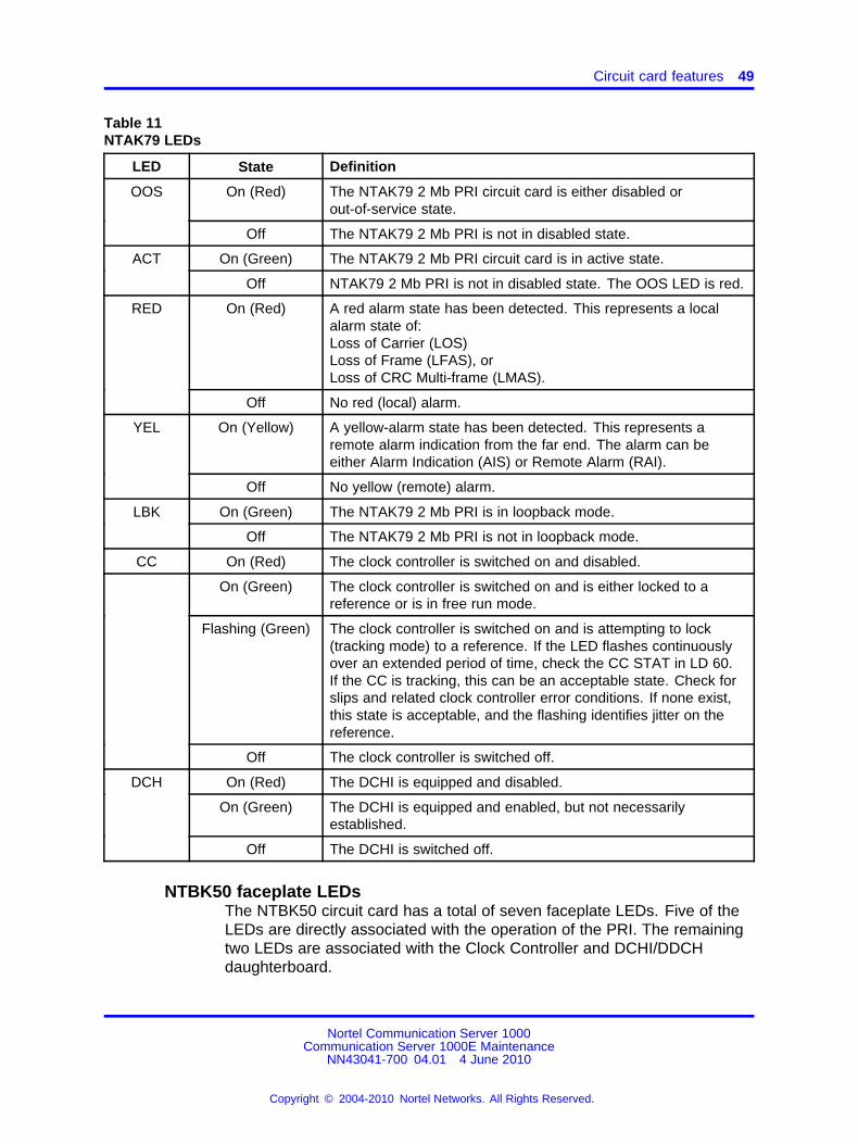
NTAK79 faceplate LEDsThe NTAK79 2 Mb PRI circuit card has a total of seven faceplate LEDs.Five of the LEDs are directly associated with the operation of the PrimaryRate interface (PRI). The remaining two LEDs are associated with theonboard Clock Controller and the onboard D-channel interface (DCHI).
The NTAK79 faceplate LEDs are described in Table 11 "NTAK79 LEDs"(page 49).
Nortel Communication Server 1000Communication Server 1000E Maintenance
NN43041-700 04.01 4 June 2010
Copyright © 2004-2010 Nortel Networks. All Rights Reserved.
.
Circuit card features 49
Table 11NTAK79 LEDs
LED State Definition
On (Red) The NTAK79 2 Mb PRI circuit card is either disabled orout-of-service state.
OOS
Off The NTAK79 2 Mb PRI is not in disabled state.
On (Green) The NTAK79 2 Mb PRI circuit card is in active state.ACT
Off NTAK79 2 Mb PRI is not in disabled state. The OOS LED is red.
On (Red) A red alarm state has been detected. This represents a localalarm state of:Loss of Carrier (LOS)Loss of Frame (LFAS), orLoss of CRC Multi-frame (LMAS).
RED
Off No red (local) alarm.
On (Yellow) A yellow-alarm state has been detected. This represents aremote alarm indication from the far end. The alarm can beeither Alarm Indication (AIS) or Remote Alarm (RAI).
YEL
Off No yellow (remote) alarm.
On (Green) The NTAK79 2 Mb PRI is in loopback mode.LBK
Off The NTAK79 2 Mb PRI is not in loopback mode.
CC On (Red) The clock controller is switched on and disabled.
On (Green) The clock controller is switched on and is either locked to areference or is in free run mode.
Flashing (Green) The clock controller is switched on and is attempting to lock(tracking mode) to a reference. If the LED flashes continuouslyover an extended period of time, check the CC STAT in LD 60.If the CC is tracking, this can be an acceptable state. Check forslips and related clock controller error conditions. If none exist,this state is acceptable, and the flashing identifies jitter on thereference.
Off The clock controller is switched off.
On (Red) The DCHI is equipped and disabled.
On (Green) The DCHI is equipped and enabled, but not necessarilyestablished.
DCH
Off The DCHI is switched off.
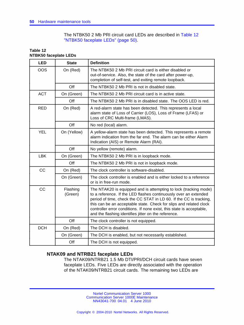
NTBK50 faceplate LEDsThe NTBK50 circuit card has a total of seven faceplate LEDs. Five of theLEDs are directly associated with the operation of the PRI. The remainingtwo LEDs are associated with the Clock Controller and DCHI/DDCHdaughterboard.
Nortel Communication Server 1000Communication Server 1000E Maintenance
NN43041-700 04.01 4 June 2010
Copyright © 2004-2010 Nortel Networks. All Rights Reserved.
.
50 Hardware maintenance tools
The NTBK50 2 Mb PRI circuit card LEDs are described in Table 12"NTBK50 faceplate LEDs" (page 50).
Table 12NTBK50 faceplate LEDs
LED State Definition
OOS On (Red) The NTBK50 2 Mb PRI circuit card is either disabled orout-of-service. Also, the state of the card after power-up,completion of self-test, and exiting remote loopback.
Off The NTBK50 2 Mb PRI is not in disabled state.
ACT On (Green) The NTBK50 2 Mb PRI circuit card is in active state.
Off The NTBK50 2 Mb PRI is in disabled state. The OOS LED is red.
RED On (Red) A red-alarm state has been detected. This represents a localalarm state of Loss of Carrier (LOS), Loss of Frame (LFAS) orLoss of CRC Multi-frame (LMAS).
Off No red (local) alarm.
YEL On (Yellow) A yellow-alarm state has been detected. This represents a remotealarm indication from the far end. The alarm can be either AlarmIndication (AIS) or Remote Alarm (RAI).
Off No yellow (remote) alarm.
On (Green) The NTBK50 2 Mb PRI is in loopback mode.LBK
Off The NTBK50 2 Mb PRI is not in loopback mode.
On (Red) The clock controller is software-disabled.CC
On (Green) The clock controller is enabled and is either locked to a referenceor is in free-run mode.
CC Flashing(Green)
The NTAK20 is equipped and is attempting to lock (tracking mode)to a reference. If the LED flashes continuously over an extendedperiod of time, check the CC STAT in LD 60. If the CC is tracking,this can be an acceptable state. Check for slips and related clockcontroller error conditions. If none exist, this state is acceptable,and the flashing identifies jitter on the reference.
Off The clock controller is not equipped.
On (Red) The DCH is disabled.
On (Green) The DCH is enabled, but not necessarily established.
DCH
Off The DCH is not equipped.
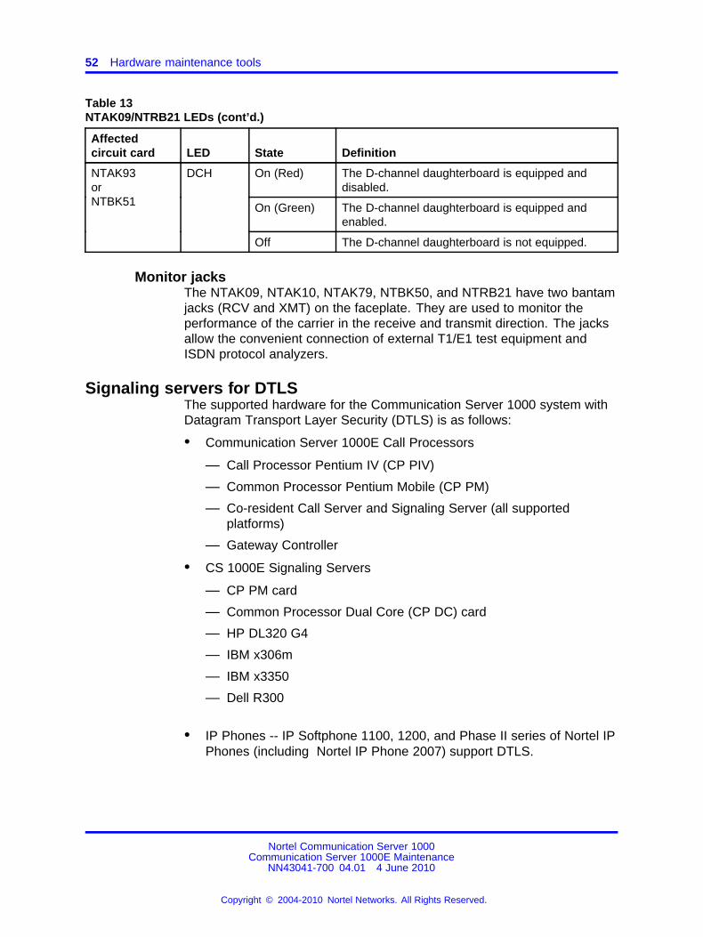
NTAK09 and NTRB21 faceplate LEDsThe NTAK09/NTRB21 1.5 Mb DTI/PRI/DCH circuit cards have sevenfaceplate LEDs. Five LEDs are directly associated with the operationof the NTAK09/NTRB21 circuit cards. The remaining two LEDs are
Nortel Communication Server 1000Communication Server 1000E Maintenance
NN43041-700 04.01 4 June 2010
Copyright © 2004-2010 Nortel Networks. All Rights Reserved.
.

Circuit card features 51
associated with the optional daughterboards. The first of these LEDsindicates the status of the NTAK20 Clock Controller daughterboard. Thesecond LED indicates the status of the D-channel interface.
Table 13 "NTAK09/NTRB21 LEDs" (page 51)describes the LEDs foundon the NTAK09/NTRB21 DTI/PRI/DCH circuit cards. Only one of the fiveLEDs is on at one time.
Table 13NTAK09/NTRB21 LEDs
Affectedcircuit card LED State Definition
On (Red) The circuit card is disabled.DIS
Off The circuit card is not in disabled state.
On (Green) The circuit card is in active state. No alarmstates exist, the card is not disabled, nor is it in aloopback state.
ACT
Off An alarm state or loopback state exists, or thecard is disabled. See other faceplate LEDs foradditional information.
On (Red) A red-alarm state is detected.RED
Off No red alarm.
On (Yellow) A yellow-alarm state is detected.
NTAK09orNTRB21
YEL
Off No yellow alarm.
On (Green) The card is in loopback mode.LBK
Off The card is not in loopback mode.
On (Red) The D-channel is equipped and disabled.
On (Green) The D-channel is equipped and enabled.
DCH
Off The D-channel is not equipped.
On (Red) The NTAK20 is equipped and disabled.
On (Green) The NTAK20 is equipped and is either locked to areference or is in free-run mode.
Flashing(Green)
The NTAK20 is equipped and is attempting to lock(tracking mode) to a reference. If the LED flashescontinuously over an extended period of time,check the CC STAT in LD 60. If the CC is tracking,this can be an acceptable state. Check for slipsand related clock controller error conditions.If none exist, this state is acceptable, and theflashing is identifies jitter on the reference.
NTAK20 CC
Off The NTAK20 is not equipped.
Nortel Communication Server 1000Communication Server 1000E Maintenance
NN43041-700 04.01 4 June 2010
Copyright © 2004-2010 Nortel Networks. All Rights Reserved.
.
52 Hardware maintenance tools
Table 13NTAK09/NTRB21 LEDs (cont’d.)
Affectedcircuit card LED State Definition
On (Red) The D-channel daughterboard is equipped anddisabled.
On (Green) The D-channel daughterboard is equipped andenabled.
NTAK93orNTBK51
DCH
Off The D-channel daughterboard is not equipped.
Monitor jacksThe NTAK09, NTAK10, NTAK79, NTBK50, and NTRB21 have two bantamjacks (RCV and XMT) on the faceplate. They are used to monitor theperformance of the carrier in the receive and transmit direction. The jacksallow the convenient connection of external T1/E1 test equipment andISDN protocol analyzers.
Signaling servers for DTLSThe supported hardware for the Communication Server 1000 system withDatagram Transport Layer Security (DTLS) is as follows:
• Communication Server 1000E Call Processors
— Call Processor Pentium IV (CP PIV)
— Common Processor Pentium Mobile (CP PM)
— Co-resident Call Server and Signaling Server (all supportedplatforms)
— Gateway Controller
• CS 1000E Signaling Servers
— CP PM card
— Common Processor Dual Core (CP DC) card
— HP DL320 G4
— IBM x306m
— IBM x3350
— Dell R300
• IP Phones -- IP Softphone 1100, 1200, and Phase II series of Nortel IPPhones (including Nortel IP Phone 2007) support DTLS.
Nortel Communication Server 1000Communication Server 1000E Maintenance
NN43041-700 04.01 4 June 2010
Copyright © 2004-2010 Nortel Networks. All Rights Reserved.
.
System alarms 53
CP PM faceplates LEDsThere are two LEDs on CP PM faceplate:
• Status LED
— Red indicates the power-up (by H/W) is on
— Yellow indicates that the OS is loaded (by S/W)
— Green indicates that "appstart" completed for software
• Redundancy LED
— Red indicates boot up (by HW) is on.
— Blank indicates when the OS starts (by S/W)
System alarmsMajor and minor alarms can be displayed on the attendant consolewhen connected to the system. However, attendant consoles cannotbe connected to an MG 1000T and therefore cannot display MG 1000Talarms.
Major alarmsA major alarm indicates a fault that seriously interferes with callprocessing. The causes of major alarms are listed in Table 14 "Causes ofmajor and minor alarms" (page 54).
When an MG 1000E is equipped with a power fail transfer unit (PFTU),a major alarm causes designated analog (500/2500-type) telephones toconnect directly to Central Office trunks. This is called a line transfer.
Minor alarmsA minor alarm indicates that the system hardware or software has detecteda fault requiring attention. The causes of minor alarms are listed in Table14 "Causes of major and minor alarms" (page 54).
A minor alarm is indicated on attendant consoles in customer groupsaffected by the fault. A minor alarm indication on the console is anoptional feature, enabled and disabled on a customer basis through dataadministration procedures.
Nortel Communication Server 1000Communication Server 1000E Maintenance
NN43041-700 04.01 4 June 2010
Copyright © 2004-2010 Nortel Networks. All Rights Reserved.
.
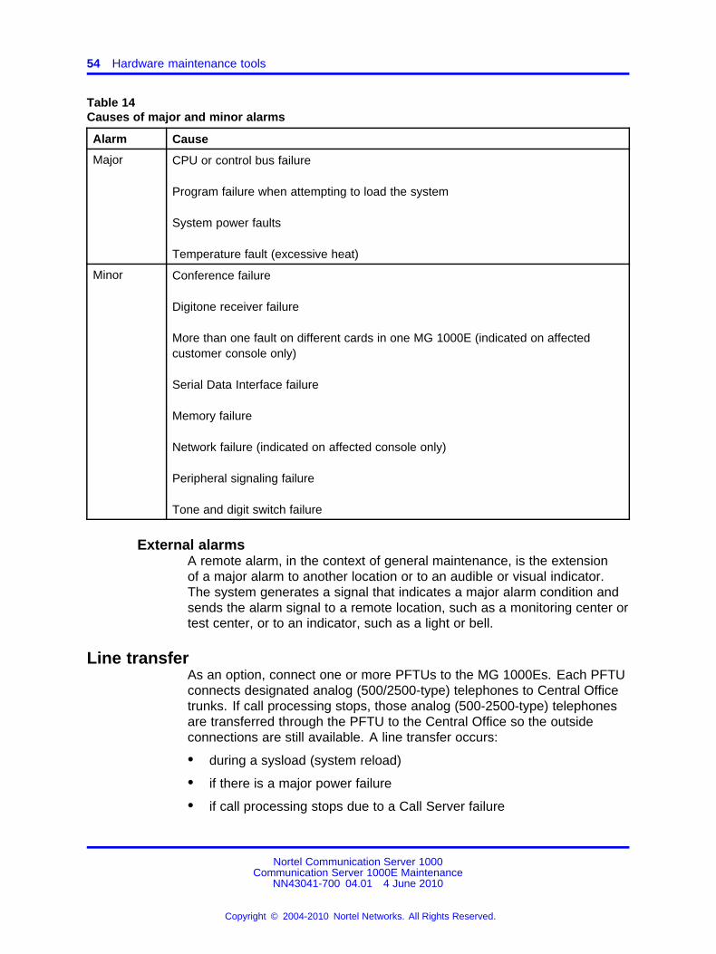
54 Hardware maintenance tools
Table 14Causes of major and minor alarms
Alarm Cause
Major CPU or control bus failure
Program failure when attempting to load the system
System power faults
Temperature fault (excessive heat)
Minor Conference failure
Digitone receiver failure
More than one fault on different cards in one MG 1000E (indicated on affectedcustomer console only)
Serial Data Interface failure
Memory failure
Network failure (indicated on affected console only)
Peripheral signaling failure
Tone and digit switch failure
External alarmsA remote alarm, in the context of general maintenance, is the extensionof a major alarm to another location or to an audible or visual indicator.The system generates a signal that indicates a major alarm condition andsends the alarm signal to a remote location, such as a monitoring center ortest center, or to an indicator, such as a light or bell.
Line transferAs an option, connect one or more PFTUs to the MG 1000Es. Each PFTUconnects designated analog (500/2500-type) telephones to Central Officetrunks. If call processing stops, those analog (500-2500-type) telephonesare transferred through the PFTU to the Central Office so the outsideconnections are still available. A line transfer occurs:
• during a sysload (system reload)
• if there is a major power failure
• if call processing stops due to a Call Server failure
Nortel Communication Server 1000Communication Server 1000E Maintenance
NN43041-700 04.01 4 June 2010
Copyright © 2004-2010 Nortel Networks. All Rights Reserved.
.

External power loss 55
• if there is a loss of power to the MG 1000E
• if there is a loss of power to the PFTU
• if a line transfer switch on the attendant console is turned on
External power lossYou can connect reserve (backup) power supplies to the system, that is,uninterruptible power supplies (UPS) for AC-powered systems. If the mainsource of external power is lost, power to the system is maintained by theUPS.
Nortel Communication Server 1000Communication Server 1000E Maintenance
NN43041-700 04.01 4 June 2010
Copyright © 2004-2010 Nortel Networks. All Rights Reserved.
.

56 Hardware maintenance tools
Nortel Communication Server 1000Communication Server 1000E Maintenance
NN43041-700 04.01 4 June 2010
Copyright © 2004-2010 Nortel Networks. All Rights Reserved.
.
57.
Software maintenance tools
ContentsThis section contains the following topics:
• “Introduction” (page 57)
• “Maintenance applications” (page 58)
• “Diagnostic programs” (page 58)
• “Media Gateway Controller Local Diagnostic Shells” (page 63)
• “Interactive diagnostics” (page 66)
• “Boot MGC to the Gold Image” (page 67)
• “CS1000 Software Logs” (page 68)
• “Supported DTLS Ciphers” (page 69)
• “Advanced Cryptography Support” (page 69)
IntroductionSoftware maintenance tools help to identify and clear faults, and provideself-checking capabilities. Various software maintenance tools areavailable for the CS 1000:
• “Diagnostic programs” (page 58) monitor a variety of operations, detectfaults, and initiate a corrective action during normal call processing.
• “Interactive diagnostics” (page 66) test hardware, isolate faults, andverify fault clearing.
• “Element Manager” (page 155) provides the means to check statusand issue a variety of commands.
Nortel Communication Server 1000Communication Server 1000E Maintenance
NN43041-700 04.01 4 June 2010
Copyright © 2004-2010 Nortel Networks. All Rights Reserved.
.
58 Software maintenance tools
Maintenance applicationsCS 1000 systems have over 600 overlay-based maintenance commands.To maintain a CS 1000 system using system terminals, you mustremember, or look up, which overlay has the appropriate commands andthe syntax of each command.
Element Manager (EM) eliminates the need to remember many of thesecommands by providing a subset of overlay functions for maintenance ofthe Call Server, MG 1000Es, Signaling Servers, and Voice Gateway MediaCards.
Diagnostic programsDiagnostic software programs monitor system operations, detect faults,and clear faults. Some programs run continuously, while some arescheduled.
Diagnostic programs are resident or nonresident software programs.Resident programs, such as the Error Monitor and Resident TrunkDiagnostic, are always present in system memory. Nonresident programs,such as the Input/Output Diagnostic and Core Equipment Diagnostic, areused as Midnight and Background Routines or for interactive diagnostics.Nonresident programs are loaded from the system disk and are run asscheduled or upon request.
See Software Input/Output Reference – Maintenance NN43001-711 andSoftware Input/Output Reference – System Messages NN43001-712 fordetailed information about all diagnostic programs.
OverlaysNonresident programs are also called overlays or loads. They areidentified by a title and a number preceded by the mnemonic for load (forexample, Trunk Diagnostic — LD 36).
CS 1000EThe CS 1000E Core Call Server and MG 1000Es support the overlaycommands and TN format (l s c u).
However, a number of maintenance commands are either not supportedor not applicable to the MG 1000E. Table 15 "Unsupported overlaycommands for MG 1000E" (page 58) lists the commands that are notsupported in the MG 1000Es.
Table 15Unsupported overlay commands for MG 1000E
LD Unsupported commands
30 CPED, DISL, ENLL, LDIS, LENL, LOOP, RPED, SLFT, STEI, TIET, TTSM, and TTWI
Nortel Communication Server 1000Communication Server 1000E Maintenance
NN43041-700 04.01 4 June 2010
Copyright © 2004-2010 Nortel Networks. All Rights Reserved.
.
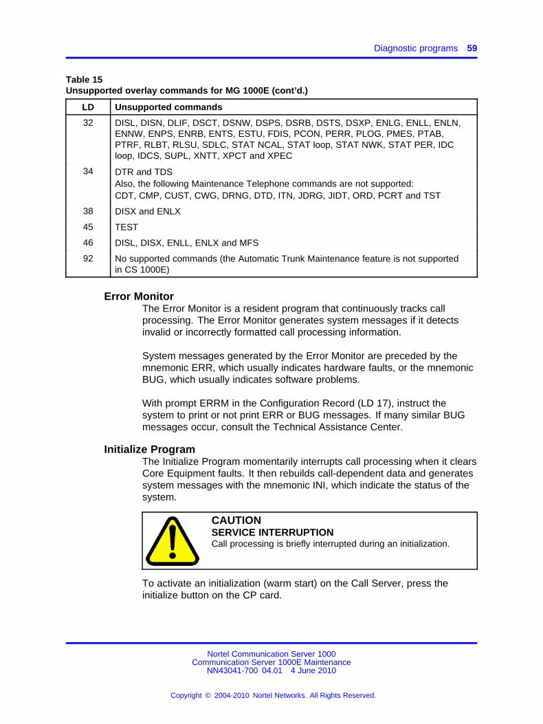
Diagnostic programs 59
Table 15Unsupported overlay commands for MG 1000E (cont’d.)
LD Unsupported commands
32 DISL, DISN, DLIF, DSCT, DSNW, DSPS, DSRB, DSTS, DSXP, ENLG, ENLL, ENLN,ENNW, ENPS, ENRB, ENTS, ESTU, FDIS, PCON, PERR, PLOG, PMES, PTAB,PTRF, RLBT, RLSU, SDLC, STAT NCAL, STAT loop, STAT NWK, STAT PER, IDCloop, IDCS, SUPL, XNTT, XPCT and XPEC
34 DTR and TDSAlso, the following Maintenance Telephone commands are not supported:CDT, CMP, CUST, CWG, DRNG, DTD, ITN, JDRG, JIDT, ORD, PCRT and TST
38 DISX and ENLX
45 TEST
46 DISL, DISX, ENLL, ENLX and MFS
92 No supported commands (the Automatic Trunk Maintenance feature is not supportedin CS 1000E)
Error MonitorThe Error Monitor is a resident program that continuously tracks callprocessing. The Error Monitor generates system messages if it detectsinvalid or incorrectly formatted call processing information.
System messages generated by the Error Monitor are preceded by themnemonic ERR, which usually indicates hardware faults, or the mnemonicBUG, which usually indicates software problems.
With prompt ERRM in the Configuration Record (LD 17), instruct thesystem to print or not print ERR or BUG messages. If many similar BUGmessages occur, consult the Technical Assistance Center.
Initialize ProgramThe Initialize Program momentarily interrupts call processing when it clearsCore Equipment faults. It then rebuilds call-dependent data and generatessystem messages with the mnemonic INI, which indicate the status of thesystem.
CAUTIONSERVICE INTERRUPTIONCall processing is briefly interrupted during an initialization.
To activate an initialization (warm start) on the Call Server, press theinitialize button on the CP card.
Nortel Communication Server 1000Communication Server 1000E Maintenance
NN43041-700 04.01 4 June 2010
Copyright © 2004-2010 Nortel Networks. All Rights Reserved.
.
60 Software maintenance tools
An initialization occurs automatically after the System Loader programruns, when a software or firmware fault is detected, and when a CoreEquipment hardware fault is detected.
Midnight and Background RoutinesIn the Configuration Record (LD 17), select the nonresident softwareprograms that run in the Midnight Routine and Background Routine. Theseroutines automatically perform maintenance checks. Programs includedin the Midnight Routine are defined with the prompt DROL (derived from"daily routine overlay"). Programs included in the Background Routine aredefined with the prompt BKGD.
The Midnight Routine runs once every 24 hours. This routine is presetto run at midnight when a system is shipped. Assign a different time inthe Configuration Record. When the Midnight Routine starts, the systemcancels any other program.
A memory test runs once a day. The Core Equipment Diagnostic (LD 35)runs as part of the Midnight Routine, even if it is not programmed.
The Background Routine runs when no other program is loaded in theoverlay area. The programs included in the Background Routine run insequence repeatedly until there is another request to use the overlay area(for example, if you log on to check the status of a circuit card) or theMidnight Routine runs.
For the CS 1000E system, include the programs listed in Table 16"Programs used in Midnight and Background Routines" (page 60) inMidnight and Background Routines. Software Audit (LD 44), andNetwork and Signaling Diagnostic (LD 30) should always be used in theBackground Routine.
The maintenance requirements and the configuration of the systemdetermine the other programs included in Midnight and BackgroundRoutines.
Table 16Programs used in Midnight and Background Routines
LD Program function
30 Network and Signaling Diagnostic
33 1.5 Mb/s Remote Peripheral Equipment Diagnostic
34 Tone and Digit Switch and Digitone Receiver
35 Core Equipment Diagnostic
36 Trunk Diagnostic 1
Nortel Communication Server 1000Communication Server 1000E Maintenance
NN43041-700 04.01 4 June 2010
Copyright © 2004-2010 Nortel Networks. All Rights Reserved.
.
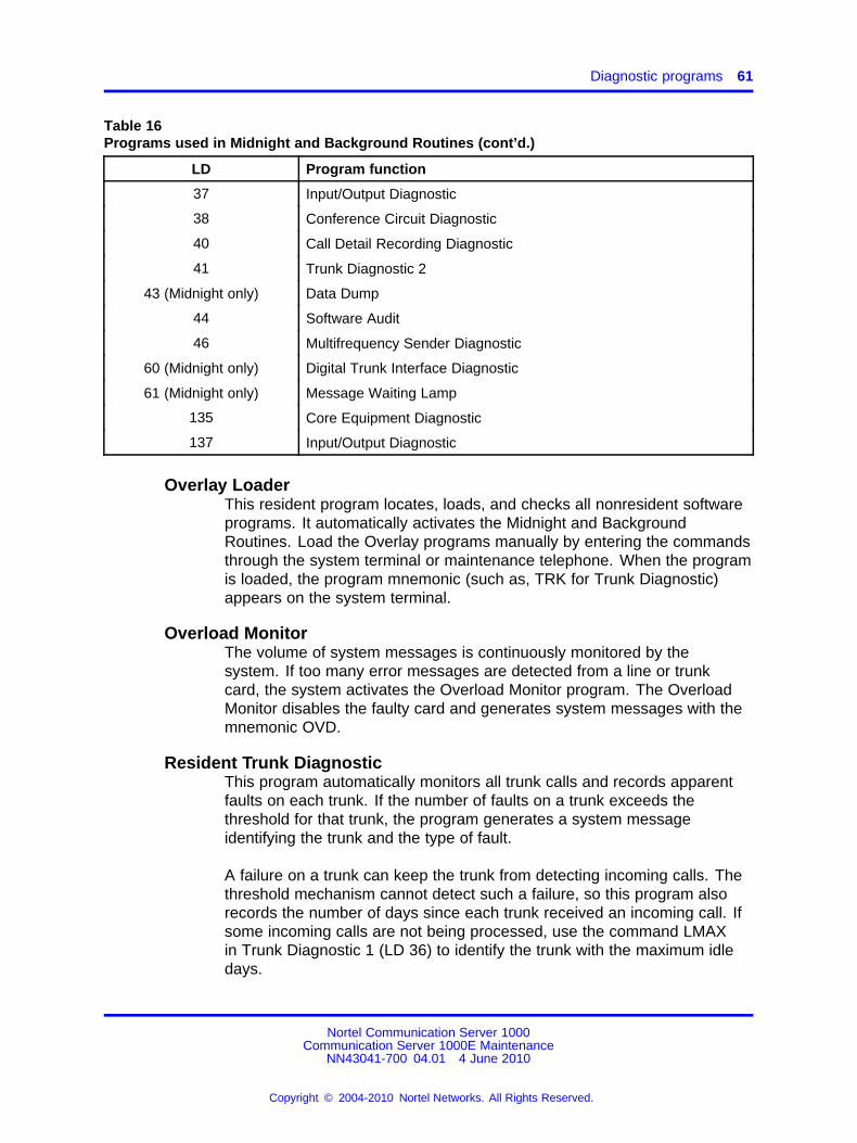
Diagnostic programs 61
Table 16Programs used in Midnight and Background Routines (cont’d.)
LD Program function
37 Input/Output Diagnostic
38 Conference Circuit Diagnostic
40 Call Detail Recording Diagnostic
41 Trunk Diagnostic 2
43 (Midnight only) Data Dump
44 Software Audit
46 Multifrequency Sender Diagnostic
60 (Midnight only) Digital Trunk Interface Diagnostic
61 (Midnight only) Message Waiting Lamp
135 Core Equipment Diagnostic
137 Input/Output Diagnostic
Overlay LoaderThis resident program locates, loads, and checks all nonresident softwareprograms. It automatically activates the Midnight and BackgroundRoutines. Load the Overlay programs manually by entering the commandsthrough the system terminal or maintenance telephone. When the programis loaded, the program mnemonic (such as, TRK for Trunk Diagnostic)appears on the system terminal.
Overload MonitorThe volume of system messages is continuously monitored by thesystem. If too many error messages are detected from a line or trunkcard, the system activates the Overload Monitor program. The OverloadMonitor disables the faulty card and generates system messages with themnemonic OVD.
Resident Trunk DiagnosticThis program automatically monitors all trunk calls and records apparentfaults on each trunk. If the number of faults on a trunk exceeds thethreshold for that trunk, the program generates a system messageidentifying the trunk and the type of fault.
A failure on a trunk can keep the trunk from detecting incoming calls. Thethreshold mechanism cannot detect such a failure, so this program alsorecords the number of days since each trunk received an incoming call. Ifsome incoming calls are not being processed, use the command LMAXin Trunk Diagnostic 1 (LD 36) to identify the trunk with the maximum idledays.
Nortel Communication Server 1000Communication Server 1000E Maintenance
NN43041-700 04.01 4 June 2010
Copyright © 2004-2010 Nortel Networks. All Rights Reserved.
.
62 Software maintenance tools
System LoaderThe System Loader program loads all call processing programs and dataand starts memory-checking diagnostics. After all required programsand data are loaded and all checks performed, the System Loader iserased from system memory, the Initialize Program runs, and normal callprocessing begins. This process is called a sysload (or system reload).The System Loader operates automatically on system power-up or if acore equipment or power fault destroys information in the system memory.
Unsuccessful DTLS negotiationDuring unsuccessful DTLS negotiation, LTPS logs one of the followingmessages:
• “DTLS handshake error - bad server certificate. Client IP = xx.xx.xx.xx”--This log message is printed when the phone is not able to validatethe server certificate or determines that the server certificate is notvalid.
• “DTLS handshake failed - bad client certificate. Client IP = xx.xx.xx.xx”--This log message prints when the mutual authentication is turned onand the server cannot validate the client certificate or determine thatthe client certificate is not valid.
Diagnostics for Linux BaseIn CS 1000, following diagnostic tools and capabilities are introduced forLinux Base systems:
• Wireshark (Ethereal) for Ethernet traffic sniffing
• Apparent Networks (Gryphon) Ethernet quality of service linksmonitoring
• system resource monitoring and alarming
• Linux OS level core dumps during abnormal OS or application failure
• MONIT applications register and set monitor thresholds and actionson error
• SNMP alarm generation and MIB-II support
• OMM reports and peg counters for each application
• Common Syslog logging infrastructure
The following table shows the diagnostic log files for Linux Base systems.
Nortel Communication Server 1000Communication Server 1000E Maintenance
NN43041-700 04.01 4 June 2010
Copyright © 2004-2010 Nortel Networks. All Rights Reserved.
.
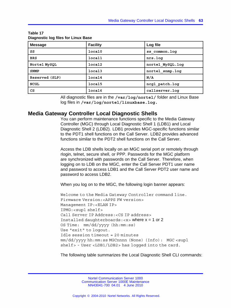
Media Gateway Controller Local Diagnostic Shells 63
Table 17Diagnostic log files for Linux Base
Message Facility Log file
SS local0 ss_common.log
BRS local1 nrs.log
Nortel MySQL local2 nortel_MySQL.log
SNMP local3 nortel_snmp.log
Reserved (SLP) local4 N/A
NCGL local5 ncgl_patch.log
CS local6 callserver.log
All diagnostic files are in the /var/log/nortel/ folder and Linux Baselog files in /var/log/nortel/linuxbase.log.
Media Gateway Controller Local Diagnostic ShellsYou can perform maintenance functions specific to the Media GatewayController (MGC) through Local Diagnostic Shell 1 (LDB1) and LocalDiagnostic Shell 2 (LDB2). LDB1 provides MGC-specific functions similarto the PDT1 shell functions on the Call Server. LDB2 provides advancedfunctions similar to the PDT2 shell functions on the Call Server.
Access the LDB shells locally on an MGC serial port or remotely throughrlogin, telnet, secure shell, or PPP. Passwords for the MGC platformare synchronized with passwords on the Call Server. Therefore, whenlogging on to LDB on the MGC, enter the Call Server PDT1 user nameand password to access LDB1 and the Call Server PDT2 user name andpassword to access LDB2.
When you log on to the MGC, the following login banner appears:
Welcome to the Media Gateway Controller command line.Firmware Version:<APPS FW version>Management IP:<ELAN IP>IPMG:<supl shelf>Call Server IP Address:<CS IP address>Installed daughterboards:<x> where x = 1 or 2OS Time: mm/dd/yyyy (hh:mm:ss)Use "exit" to logout.Idle session timeout = 20 minutesmm/dd/yyyy hh:mm:ss MGCnnnn (None) (Info): MGC <suplshelf> - User <LDB1/LDB2> has logged into the card.
The following table summarizes the Local Diagnostic Shell CLI commands:
Nortel Communication Server 1000Communication Server 1000E Maintenance
NN43041-700 04.01 4 June 2010
Copyright © 2004-2010 Nortel Networks. All Rights Reserved.
.
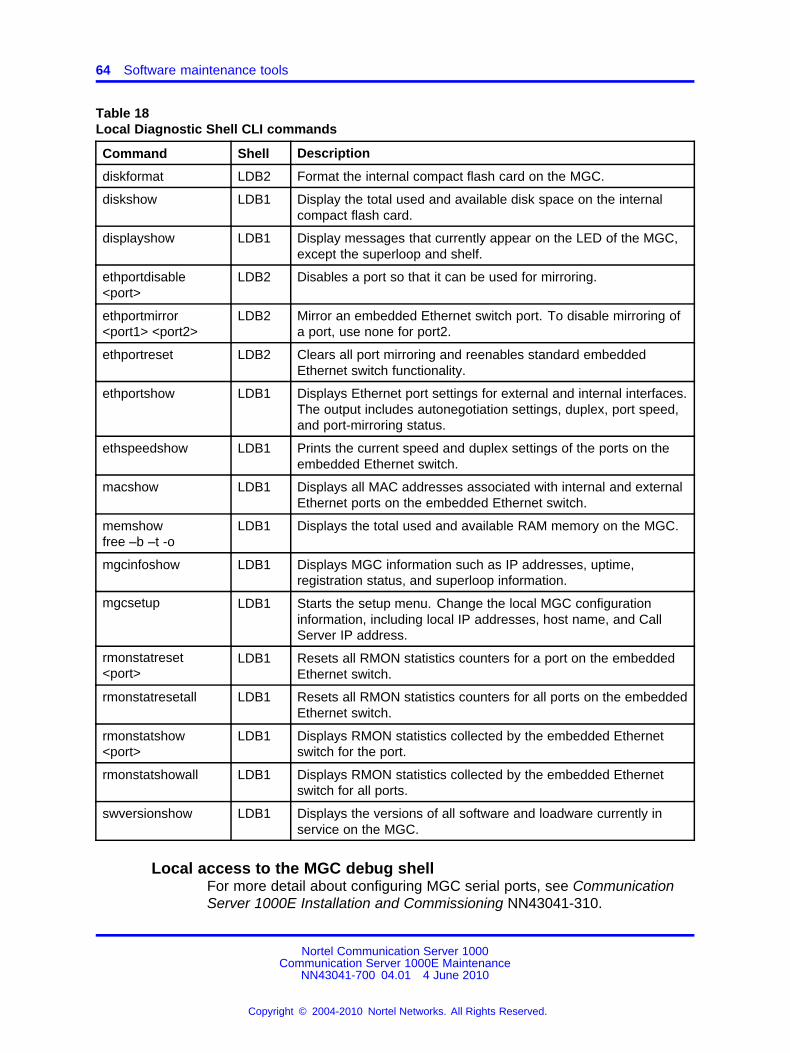
64 Software maintenance tools
Table 18Local Diagnostic Shell CLI commands
Command Shell Description
diskformat LDB2 Format the internal compact flash card on the MGC.
diskshow LDB1 Display the total used and available disk space on the internalcompact flash card.
displayshow LDB1 Display messages that currently appear on the LED of the MGC,except the superloop and shelf.
ethportdisable<port>
LDB2 Disables a port so that it can be used for mirroring.
ethportmirror<port1> <port2>
LDB2 Mirror an embedded Ethernet switch port. To disable mirroring ofa port, use none for port2.
ethportreset LDB2 Clears all port mirroring and reenables standard embeddedEthernet switch functionality.
ethportshow LDB1 Displays Ethernet port settings for external and internal interfaces.The output includes autonegotiation settings, duplex, port speed,and port-mirroring status.
ethspeedshow LDB1 Prints the current speed and duplex settings of the ports on theembedded Ethernet switch.
macshow LDB1 Displays all MAC addresses associated with internal and externalEthernet ports on the embedded Ethernet switch.
memshowfree –b –t -o
LDB1 Displays the total used and available RAM memory on the MGC.
mgcinfoshow LDB1 Displays MGC information such as IP addresses, uptime,registration status, and superloop information.
mgcsetup LDB1 Starts the setup menu. Change the local MGC configurationinformation, including local IP addresses, host name, and CallServer IP address.
rmonstatreset<port>
LDB1 Resets all RMON statistics counters for a port on the embeddedEthernet switch.
rmonstatresetall LDB1 Resets all RMON statistics counters for all ports on the embeddedEthernet switch.
rmonstatshow<port>
LDB1 Displays RMON statistics collected by the embedded Ethernetswitch for the port.
rmonstatshowall LDB1 Displays RMON statistics collected by the embedded Ethernetswitch for all ports.
swversionshow LDB1 Displays the versions of all software and loadware currently inservice on the MGC.
Local access to the MGC debug shellFor more detail about configuring MGC serial ports, see CommunicationServer 1000E Installation and Commissioning NN43041-310.
Nortel Communication Server 1000Communication Server 1000E Maintenance
NN43041-700 04.01 4 June 2010
Copyright © 2004-2010 Nortel Networks. All Rights Reserved.
.
Media Gateway Controller log file 65
When you connect to an MGC TTY that is not configured as a systemterminal, you receive no system prompt.
When you connect to an MGC TTY that is configured as a systemterminal, you automatically connect to the Call Server SL1 shell.
In either situation, the commands in the following table provide access tothe LDB and OAM shells.
Table 19Accessing MGC debug shells
Command Description
Ctrl+l, Ctrl+d, Ctrl+b Obtain an LDB prompt.
Ctrl+o, Ctrl+a, Ctrl+m Obtain an OAM prompt.
Ctrl+o, Ctrl+a, Ctrl+m Obtain an OAM prompt from the LDS command line. The LDSsession terminates after a successful logon to OAM.
Ctrl+l, Ctrl+d, Ctrl+b Obtain an LDS prompt from the OAM command line. The OAMsession terminates after a successful logon to LDB.
exit Exit LDB or OAM.
To access the Call Server Problem Determination Tool (PDT), enterCtrl+p, Ctrl+d, Ctrl+t on an MGC TTY configured as a system terminal.
Remote access to the MGC debug shellCS 1000 supports rlogin, telnet, FTP, SFTP version 3.0 and secure shell(ssh) for remote access to the Media Gateway Controller.
For remote access to the MGC, initiate an rlogin or telnet session from theremote host to the ELAN address of the MGC.
The commands in Table 19 "Accessing MGC debug shells" (page65) function remotely and locally.
Media Gateway Controller log fileA 1 MB circular log file accumulates system messages. The file, calledLog0001.rpt, is stored in the MGC directory /u/rpt. Each record contains:
• timestamp
• message mnemonic
• message description
• severity
• if applicable, the four character LED message
Nortel Communication Server 1000Communication Server 1000E Maintenance
NN43041-700 04.01 4 June 2010
Copyright © 2004-2010 Nortel Networks. All Rights Reserved.
.
66 Software maintenance tools
Log0001.rpt is a report log file, similar to the log files on the Call Serverand Signaling Server. The CLI commands to view and manage this file areidentical to the commands on the Signaling Server platform.
Table 20OAM DLOG commands
Command Description
activeDlogShow Display the current used firmware download file. SeeIP Line Fundamentals.
inactiveDlogShow Display the inactive firmware download log file. SeeIP Line Fundamentals.
dnldFailShow Display failed results in the active firmware downloadlog file. See IP Line Fundamentals.
Interactive diagnosticsLoad nonresident software programs into the memory through an SDIterminal. These programs, also called overlays or loads, are identified by atitle and a number that is preceded by the mnemonic for load (for example,Trunk Diagnostic — LD 36).
The programs used in Midnight and Background Routines are also usedmanually as interactive diagnostic programs. See Table 16 "Programsused in Midnight and Background Routines" (page 60).
Nonresident programs are used interactively with a command andresponse format. In this format, enter a command that tells the system toperform a specific task. The system performs the task and sends systemmessages indicating status or errors back to you.
With interactive diagnostics you can:
• Disable, test, and enable specific equipment.
• Verify that a reported fault still needs to be cleared.
• Verify that a repair procedure has cleared a fault.
All maintenance programs, commands, and system messages aredescribed in detail in Software Input/Output Reference – MaintenanceNN43001-711 and in Software Input/Output Reference – SystemMessages NN43001-712.
Enhanced Maintenance featureThe system software sometimes requires modifications, called patches,which are provided by Nortel Technical Assistance Centers. The commandISS in Print Routine 3 (LD 22) prints the software generic and issue. Aplus symbol (+) by the issue number means a patch is in service.
Nortel Communication Server 1000Communication Server 1000E Maintenance
NN43041-700 04.01 4 June 2010
Copyright © 2004-2010 Nortel Networks. All Rights Reserved.
.
Boot MGC to the Gold Image 67
The Enhanced Maintenance feature provides the following:
• Enable patches to automatically survive a sysload.
• Enable patches on nonresident programs.
• Records all patches in the system.
• Enable data cartridges to be shipped with preloaded patches.
If a problem occurs with a patch, the CPU sends system messages, withthe mnemonic EHM, to the system terminal or the history file.
Patch conflict issues can arise when you load individual patches or deplistpatches. When you encounter a patch conflict, patch activation is aborted.CS 1000 Release 7.0 introduces a mechanism to handle conflicts. Whenyou activate a patch, if any obsolete patches are in service, then all thosepatches are removed from the system.
Note: In CS 1000 Release 7.0, deplist does not appear during a patchwhen the Deplist is empty.
Maintenance enhancement allows a technician to upgrade a site usingthe same software generic with new or replacement patches that arepreloaded on the disk. Also, you can selectively dump specified patchesfrom core memory to disk. You can use the dump patch facility for thispurpose.
A maximum of 50 dummy globals are allowed for patches, instead of thenormal five. Use of these globals are tracked, and you are given warningmessages if attempting to use them for another patch.
Boot MGC to the Gold ImageTo boot MGC to the Gold Image you must get to the MGC bootromprompt, follow the steps Procedure 3 “Booting MGC to the Gold Image”(page 67) in to boot the MGC to Gold Image.
Procedure 3Booting MGC to the Gold Image
Step Action
1 Reboot MGC.
2 While booting, type <CTRL B> after the creation date is printedand the boot prompt is displayed.
3 At the prompt type test.
4 Select option b to change the boot options.
5 Select option 2 to boot CSP from gold image once.
Nortel Communication Server 1000Communication Server 1000E Maintenance
NN43041-700 04.01 4 June 2010
Copyright © 2004-2010 Nortel Networks. All Rights Reserved.
.
68 Software maintenance tools
6 Select option 0 to return to the previous menu.
7 Press the return key to exit menu and return to prompt.
8 Enter @ at the prompt.
The MGC boots to the Gold Image.
--End--
Compact Flash Formatting with MGC Gold ImageTo format the compact flash from the Gold Image, use Procedure 4“Formatting Compact Flash with MGC Gold Image” (page 68).
Procedure 4Formatting Compact Flash with MGC Gold Image
Step Action
1 Type <CTRL>I when prompted during the MGC gold boot.
This brings up a boot prompt.
2 At the prompt Enter diskformat "all".
This formats the MGCs internal compact flash.
3 Reboot the MGC and when it registers to the call server it getsautomatically upgrade.
--End--
CS1000 Software LogsThe CS1000 logging infrastructure is comprised of a collection of logfiles that are created and archived across multiple elements that makeup a CS1000 solution. The logs are intended to provide various levels ofinformation related to specific events that have occurred during differentoperational states of the CS1000 solution. The collected informationconsolidated in the various logs includes information related to thefollowing:
• status of software and hardware
• user administrative activity
• security events
• operational messages
• software debug messages
Nortel Communication Server 1000Communication Server 1000E Maintenance
NN43041-700 04.01 4 June 2010
Copyright © 2004-2010 Nortel Networks. All Rights Reserved.
.
Advanced Cryptography Support 69
The collected information will have a variety of uses and apply to manyaspects of system management. The users of this log information typicallyinclude network operations, security administrators, software developers,network engineering, and customer support.
For more information about logs, see System Management Reference(NN43001-600).
Supported DTLS CiphersMocana DTLS stack supports the DTLS Ciphers and is compliant withRFC4347. Mocana DTLS supports the following DTLS ciphers:
• TLS-RSA-WITH-AES-256-CBC-SHA
• TLS-RSA-WITH-AES-128-CBC-SHA
• TLS-RSA-WITH-3DES-EDE-CBC-SHA
• TLS-RSA-WITH-DES-CBC-SHA
• TLS-DHE-RSA-WITH-AES-256-CBC-SHA
• TLS-DHE-RSA-WITH-AES-128-CBC-SHA
• TLS-DHE-RSA-WITH-3DES-EDE-CBC-SHA
• TLS-DH-ANON-WITH-DES-CBC-SHA
• TLS-PSK-WITH-AES-256-CBC-SHA
• TLS-PSK-WITH-AES-128-CBC-SHA
• TLS-PSK-WITH-3DES-EDE-CBC-SHA
• TLS-RSA-PSK-WITH-AES-256-CBC-SHA
• TLS-RSA-PSK-WITH-AES-128-CBC-SHA
• TLS-RSA-PSK-WITH-3DES-EDE-CBC-SHA
• TLS-DHE-PSK-WITH-AES-256-CBC-SHA
• TLS-DHE-PSK-WITH-AES-128-CBC-SHA
• TLS-DHE-PSK-WITH-3DES-EDE-CBC-SHA
• TLS-RSA-WITH-NULL-SHA
• TLS-RSA-WITH-NULL-MD5
Advanced Cryptography SupportMocana DTLS library supports the following Advanced Cryptographies:
• Diffie-Hellman key exchange RSA
• PKCS #1, Version 1.5
Nortel Communication Server 1000Communication Server 1000E Maintenance
NN43041-700 04.01 4 June 2010
Copyright © 2004-2010 Nortel Networks. All Rights Reserved.
.
70 Software maintenance tools
• PKCS #5
• PKCS #7
• PKCS #8
• PKCS #10
• PKCS #12
• MD2
• MD4
• MD5
• SHA1
• SHA-224
• SHA-256
• SHA-384
• SHA-512
Nortel Communication Server 1000Communication Server 1000E Maintenance
NN43041-700 04.01 4 June 2010
Copyright © 2004-2010 Nortel Networks. All Rights Reserved.
.
71.
Clearing faults
ContentsThis section contains the following topics:
• “Fault clearing process” (page 71)
• “Fault indicators” (page 73)
• “Clearing Core Call Server faults” (page 75)
• “Clearing Signaling Server faults” (page 80)
• “MG 1000E faults” (page 82)
• “Clearing Core faults” (page 88)
• “Clearing MG 1000E Expansion faults” (page 91)
• “Clearing trunk faults” (page 97)
• “Clearing Terminal Server faults” (page 100)
• “Clearing IP Phone faults” (page 100)
Fault clearing processTo clear a fault in the CS 1000, follow the steps in Procedure 5 “Clearinga fault in the CS 1000” (page 71).
Procedure 5Clearing a fault in the CS 1000
Step Action
1 Observe and record all fault indicators, system messages, anduser reports.
2 Look up all system messages in Software Input/OutputReference – System Messages NN43001-712.
The interpretation of the message can identify faulty equipmentand tell you what action to take to clear the problem. If youcannot clear the fault using a Maintenance Application or throughinformation inSoftware Input/Output Reference – Maintenance
Nortel Communication Server 1000Communication Server 1000E Maintenance
NN43041-700 04.01 4 June 2010
Copyright © 2004-2010 Nortel Networks. All Rights Reserved.
.
72 Clearing faults
NN43001-711, follow the process in this chapter to isolate andclear the fault.
3 If the system messages are not current or seem incomplete,review previous messages or initialize the system for informationabout the current status, as required.
4 Try to enable or test disabled equipment.
5 Software reenable cards by disabling and reenabling them.When the cause of a fault is not clearly evident, perform asoftware test to help identify the problem.
CAUTIONWorking with ESDS devicesWear an antistatic wrist strap when handling circuitcards to prevent damage caused by static discharge.
6 Software disable the circuit cards and hardware reenable themby unseating and reinstalling the cards. To unseat a circuit card,unscrew all faceplate screws holding the card in place. (Eachcircuit card has two screws except for the Drive Carrier card,which has four). Use the faceplate latches to eject the card.When reseating a circuit card, ensure to latch it and retighten allscrews.
7 Replace equipment as necessary.
--End--
VerificationTo verify that the system is operating properly and there are no remainingfaults, follow the steps in Procedure 6 “Verifying operation” (page 72).
Procedure 6Verifying operation
Step Action
1 Ensure all LEDs on the alarm/fan module are green.
2 Make sure all circuit cards that could have been removed arereinserted in their assigned location and enabled.
3 Ensure the system utility card has the correct DIP switchsettings for CPU 0 or CPU 1 as required. Also ensure that theenable/disable switch is configured to enable.
4 Make sure all wiring and connectors that could have beendisconnected are reconnected.
5 Configure the midnight routine to run after logging out of thesystem by entering:
Nortel Communication Server 1000Communication Server 1000E Maintenance
NN43041-700 04.01 4 June 2010
Copyright © 2004-2010 Nortel Networks. All Rights Reserved.
.
Fault indicators 73
LD 135MIDN
End the session in LD 135 and log out of the system by entering:
**** (four asterisks)LOGO
The midnight routine runs now.
6 Check system messages produced when the midnight routineruns. Clear any faults indicated.
ATTENTIONUsing the STAD commandEffective in CS 1000, Release 5.0, only users that have SEC_ADMIN privilegescan change the system time and date. For more information about securityenhancements, see Security Management Fundamentals (NN43001-604).
7 If a sysload occurred while clearing a fault, reset the correct timeand date by entering:
LD 2STAD (day) (month) (year) (hour) (minute) (second)
Check the time and date entered:
TTAD
End the session in LD 2 and log out of the system:**** (four asterisks)
LOGO
8 Replace any covers that were removed.
9 Tag defective equipment with a description of the fault and returnit to a repair center.
--End--
Fault indicatorsWhen there is a fault in the system, you can receive notification by anycombination of the following indicators:
• system messages
• visual fault indicators
• user reports
Nortel Communication Server 1000Communication Server 1000E Maintenance
NN43041-700 04.01 4 June 2010
Copyright © 2004-2010 Nortel Networks. All Rights Reserved.
.
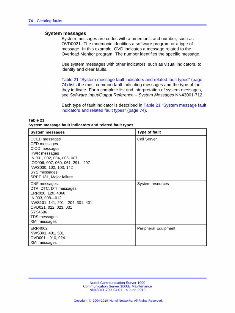
74 Clearing faults
System messagesSystem messages are codes with a mnemonic and number, such asOVD0021. The mnemonic identifies a software program or a type ofmessage. In this example, OVD indicates a message related to theOverload Monitor program. The number identifies the specific message.
Use system messages with other indicators, such as visual indicators, toidentify and clear faults.
Table 21 "System message fault indicators and related fault types" (page74) lists the most common fault-indicating messages and the type of faultthey indicate. For a complete list and interpretation of system messages,see Software Input/Output Reference – System Messages NN43001-712.
Each type of fault indicator is described in Table 21 "System message faultindicators and related fault types" (page 74).
Table 21System message fault indicators and related fault types
System messages Type of fault
CCED messagesCED messagesCIOD messagesHWR messagesINI001, 002, 004, 005, 007IOD006, 007, 060, 061, 291—297NWS030, 102, 103, 142SYS messagesSRPT 181, Major failure
Call Server
CNF messagesDTA, DTC, DTI messagesERR020, 120, 4060INI003, 008—012NWS101, 141, 201—204, 301, 401OVD021, 022, 023, 031SYS4696TDS messagesXMI messages
System resources
ERR4062NWS301, 401, 501OVD001—010, 024XMI messages
Peripheral Equipment
Nortel Communication Server 1000Communication Server 1000E Maintenance
NN43041-700 04.01 4 June 2010
Copyright © 2004-2010 Nortel Networks. All Rights Reserved.
.
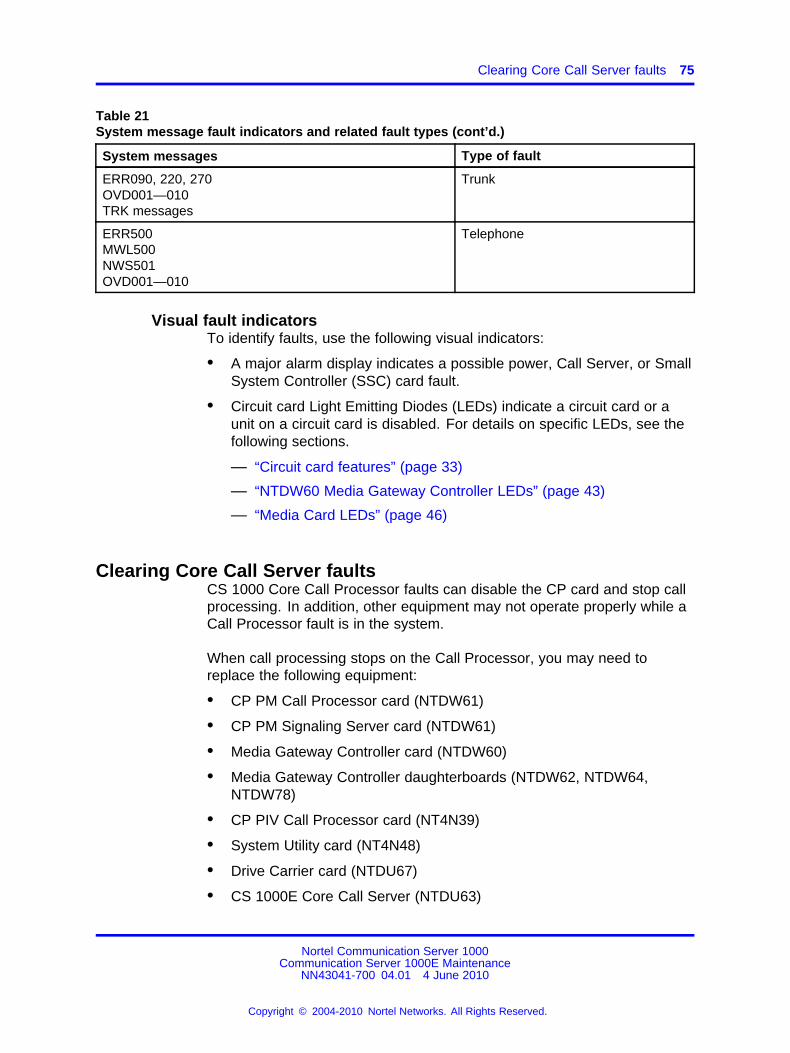
Clearing Core Call Server faults 75
Table 21System message fault indicators and related fault types (cont’d.)
System messages Type of fault
ERR090, 220, 270OVD001—010TRK messages
Trunk
ERR500MWL500NWS501OVD001—010
Telephone
Visual fault indicatorsTo identify faults, use the following visual indicators:
• A major alarm display indicates a possible power, Call Server, or SmallSystem Controller (SSC) card fault.
• Circuit card Light Emitting Diodes (LEDs) indicate a circuit card or aunit on a circuit card is disabled. For details on specific LEDs, see thefollowing sections.
— “Circuit card features” (page 33)
— “NTDW60 Media Gateway Controller LEDs” (page 43)
— “Media Card LEDs” (page 46)
Clearing Core Call Server faultsCS 1000 Core Call Processor faults can disable the CP card and stop callprocessing. In addition, other equipment may not operate properly while aCall Processor fault is in the system.
When call processing stops on the Call Processor, you may need toreplace the following equipment:
• CP PM Call Processor card (NTDW61)
• CP PM Signaling Server card (NTDW61)
• Media Gateway Controller card (NTDW60)
• Media Gateway Controller daughterboards (NTDW62, NTDW64,NTDW78)
• CP PIV Call Processor card (NT4N39)
• System Utility card (NT4N48)
• Drive Carrier card (NTDU67)
• CS 1000E Core Call Server (NTDU63)
Nortel Communication Server 1000Communication Server 1000E Maintenance
NN43041-700 04.01 4 June 2010
Copyright © 2004-2010 Nortel Networks. All Rights Reserved.
.
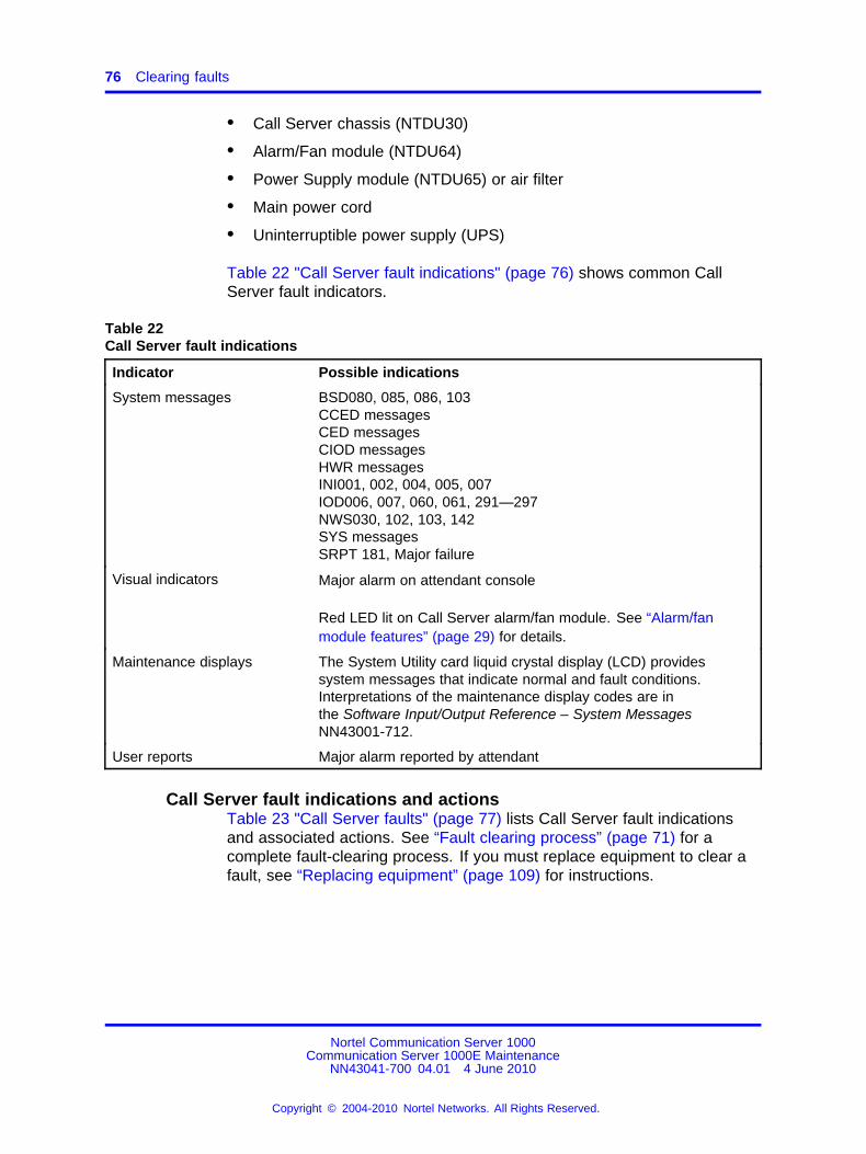
76 Clearing faults
• Call Server chassis (NTDU30)
• Alarm/Fan module (NTDU64)
• Power Supply module (NTDU65) or air filter
• Main power cord
• Uninterruptible power supply (UPS)
Table 22 "Call Server fault indications" (page 76) shows common CallServer fault indicators.
Table 22Call Server fault indications
Indicator Possible indications
System messages BSD080, 085, 086, 103CCED messagesCED messagesCIOD messagesHWR messagesINI001, 002, 004, 005, 007IOD006, 007, 060, 061, 291—297NWS030, 102, 103, 142SYS messagesSRPT 181, Major failure
Visual indicators Major alarm on attendant console
Red LED lit on Call Server alarm/fan module. See “Alarm/fanmodule features” (page 29) for details.
Maintenance displays The System Utility card liquid crystal display (LCD) providessystem messages that indicate normal and fault conditions.Interpretations of the maintenance display codes are inthe Software Input/Output Reference – System MessagesNN43001-712.
User reports Major alarm reported by attendant
Call Server fault indications and actionsTable 23 "Call Server faults" (page 77) lists Call Server fault indicationsand associated actions. See “Fault clearing process” (page 71) for acomplete fault-clearing process. If you must replace equipment to clear afault, see “Replacing equipment” (page 109) for instructions.
Nortel Communication Server 1000Communication Server 1000E Maintenance
NN43041-700 04.01 4 June 2010
Copyright © 2004-2010 Nortel Networks. All Rights Reserved.
.
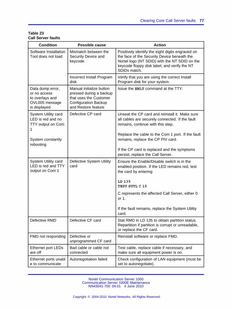
Clearing Core Call Server faults 77
Table 23Call Server faults
Condition Possible cause Action
Mismatch between theSecurity Device andkeycode
Positively identify the eight digits engraved onthe face of the Security Device beneath theNortel logo (NT SDID) with the NT SDID on thekeycode floppy disk label, and verify the NTSDIDs match.
Software InstallationTool does not load
Incorrect Install Programdisk
Verify that you are using the correct InstallProgram disk for your system.
Data dump error,or no accessto overlays andOVL005 messageis displayed
Manual initialize buttonpressed during a backupthat uses the CustomerConfiguration Backupand Restore feature
Issue the ENLT command at the TTY.
System Utility cardLED is red and noTTY output on Com1
System constantlyrebooting
Defective CP card Unseat the CP card and reinstall it. Make sureall cables are securely connected. If the faultremains, continue with this step.
Replace the cable to the Com 1 port. If the faultremains, replace the CP PIV card.
If the CP card is replaced and the symptomspersist, replace the Call Server.
System Utility cardLED is red and TTYoutput on Com 1
Defective System Utilitycard
Ensure the Enable/Disable switch is in theenabled position. If the LED remains red, testthe card by entering
LD 135TEST SUTL C 15
C represents the affected Call Server, either 0or 1.
If the fault remains, replace the System Utilitycard.
Defective RMD Defective CF card Stat RMD in LD 135 to obtain partition status.Repartition if partition is corrupt or unreadable,or replace the CF card.
FMD not responding Defective orunprogrammed CF card
Reinstall software or replace FMD.
Ethernet port LEDsare off
Bad cable or cable notconnected
Test cable, replace cable if necessary, andmake sure all equipment power is on.
Ethernet ports unable to communicate
Autonegotiation failed Check configuration of LAN equipment (must beset to autonegotiate).
Nortel Communication Server 1000Communication Server 1000E Maintenance
NN43041-700 04.01 4 June 2010
Copyright © 2004-2010 Nortel Networks. All Rights Reserved.
.
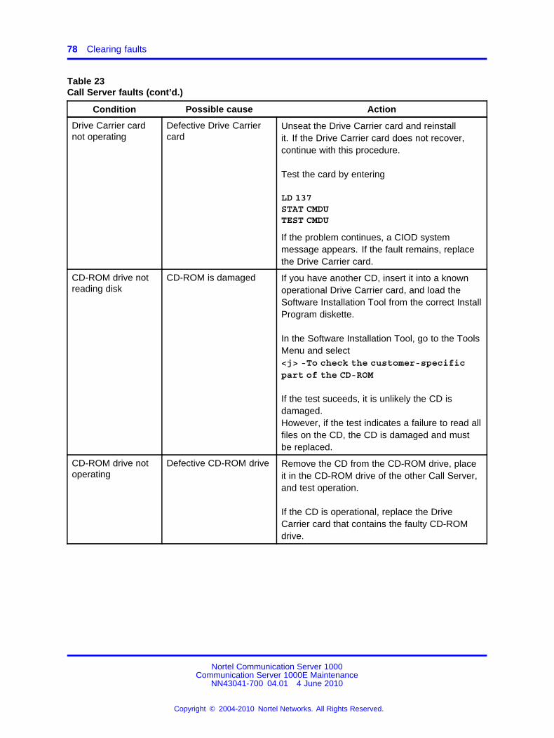
78 Clearing faults
Table 23Call Server faults (cont’d.)
Condition Possible cause Action
Drive Carrier cardnot operating
Defective Drive Carriercard
Unseat the Drive Carrier card and reinstallit. If the Drive Carrier card does not recover,continue with this procedure.
Test the card by entering
LD 137STAT CMDUTEST CMDU
If the problem continues, a CIOD systemmessage appears. If the fault remains, replacethe Drive Carrier card.
CD-ROM drive notreading disk
CD-ROM is damaged If you have another CD, insert it into a knownoperational Drive Carrier card, and load theSoftware Installation Tool from the correct InstallProgram diskette.
In the Software Installation Tool, go to the ToolsMenu and select<j> -To check the customer-specificpart of the CD-ROM
If the test suceeds, it is unlikely the CD isdamaged.However, if the test indicates a failure to read allfiles on the CD, the CD is damaged and mustbe replaced.
CD-ROM drive notoperating
Defective CD-ROM drive Remove the CD from the CD-ROM drive, placeit in the CD-ROM drive of the other Call Server,and test operation.
If the CD is operational, replace the DriveCarrier card that contains the faulty CD-ROMdrive.
Nortel Communication Server 1000Communication Server 1000E Maintenance
NN43041-700 04.01 4 June 2010
Copyright © 2004-2010 Nortel Networks. All Rights Reserved.
.
Clearing Core Call Server faults 79
Table 23Call Server faults (cont’d.)
Condition Possible cause Action
High room temperature Adjust room temperature as necessary. Allowthe system to cool for a few minutes and thenreset the system.
Defective alarm/fanmodule
Verify that the fans in the alarm fan/module areoperational.Unseat and reinstall alarm/fan module. If thefault continues, replace the alarm/fan module.
Fan LED ortemperature LEDis red
Power supply air filter isobstructed
Check filter to ensure it is clean. If the filter isdirty or damaged, clean or replace the filteras described in Procedure 27 “Cleaning andreplacing the power supply air filter” (page 141).
The power LED isred
Power fault or defectivepower supply module
Turn off the power switch at the rear of the CallServer and remove the power cord. Loosenthe locking screw at the front of the module.Unseat and reseat the module firmly. Tightenthe locking screw and replace the power cord.Turn on the power switch and observe if failurehas cleared.
If the fault continues, replace the power supplymodule.
Note: When in shutdown mode, the power supply continues to power the LEDs on the alarm/fanmodule that indicate a power supply failure.
Power switch is off Turn the power switch on.
Disconnected powercable
Check the power cable connection to thepower supply module. Ensure that it is firmlyconnected.
If the cable is connected, check the power cableconnection to the other Call Server.
If all power cables are firmly connected, go tothe next possible cause.
All LEDs in the CallServer are off
Defective power cable Replace power cable.
WARNINGThe following tests are performed on a live power connection.
Nortel Communication Server 1000Communication Server 1000E Maintenance
NN43041-700 04.01 4 June 2010
Copyright © 2004-2010 Nortel Networks. All Rights Reserved.
.
80 Clearing faults
Table 23Call Server faults (cont’d.)
Condition Possible cause Action
No power at outlet With a meter or test lamp, test for AC power atthe outlet.
If no power is available at the outlet when ACpower is supplied through a UPS unit, repair orreplace the UPS following the manufacturer’sinstructions.
If no power is available at the outlet when ACpower is supplied through commercial service(not through a UPS), take the necessary stepsto have the commercial power restored.
If power is available at the outlet, go to the nextpossible cause.
Defective power supply Turn the power switch on the back of the powersupply to OFF (down). Wait at least 60 seconds,and then turn the switch back to ON (up).
Ensure power supply is well seated and thelocking screw is tightened.
If all LEDs remain off, or the power LED onthe alarm/fan module is red, replace the powersupply.
Defective alarm/fanmodule
If the Nortel display remains lit and thealarm/fan LEDs are all off, ensure that thealarm/fan module is well seated and the lockingscrew is tightened.
If it is still not operating properly, replace thealarm/fan module.
All LEDs in the CallServer are off
Defective Call Server If the power supply and alarm/fan module arereplaced and the symptoms persist, replace theCall Server.
Clearing Signaling Server faultsThe Signaling Server is an OEM or commercial-off-the-shelf (COTS) 1Userver that provides signaling for the system. Signaling Servers haveELAN and TLAN network interfaces that are connected to an Ethernetswitch through CAT5 cables. Signaling Servers have two serial ports and
Nortel Communication Server 1000Communication Server 1000E Maintenance
NN43041-700 04.01 4 June 2010
Copyright © 2004-2010 Nortel Networks. All Rights Reserved.
.
Clearing Signaling Server faults 81
visual indicators for maintenance. Signaling Servers have three pushbuttons, one each for power, reset, and INI (initialization). No support isavailable for the INI button, USB ports, keyboard port, and mouse port.
Table 24Signaling Server Diagnosis
Condition Possible Cause Action
No power to system Check power cable.Signaling Server not running. AllLEDs off Power supply failed Replace Signaling Server.
Signaling Server running with nofan noise
Fan failed Replace Signaling Server.
CD-ROM drive tries to accessCD-ROM but stops
CD-ROM media is corrupted Replace CD-ROM disk.
CD-ROM drive not accessingCD-ROM. No green light.
CD-ROM Drive failed Replace Signaling Server.
100BT light not on Auto Negotiate Failed Provision Ethernet Switch to100MB. Switch Auto Negotiateoff.
Bad connection to Ethernetswitch
Check power on Ethernetswitch.Check CAT5 Ethernet cable.
Check Ethernet switch port.
ELAN or TLAN network interfaceLink light not active
Failed network interface Replace Signaling Server.
Hard drive not formatted Install software. See LinuxPlatform Base and ApplicationsInstallation and Commissioning(NN43001-315).
Hard drive with bad sectors Install software and use diskcheck option. Replace Server ifdisk check fails.
Signaling Server unable to bootfrom hard drive
Hard drive failed Replace Signaling Server
Signaling Server not respondingthrough serial port.
Software failed Reset Signaling Server
Signaling Server boots and thenstops.
No software loaded Load software. See LinuxPlatform Base and ApplicationsInstallation and Commissioning(NN43001-315).
Nortel Communication Server 1000Communication Server 1000E Maintenance
NN43041-700 04.01 4 June 2010
Copyright © 2004-2010 Nortel Networks. All Rights Reserved.
.
82 Clearing faults
MG 1000E faultsClearing ELAN network interface faults
On each MG 1000E, the MGC card connects to the ELAN subnet throughthe ELAN network interface. A CAT5 or 100BaseT Ethernet cableconnects the ELAN network interface to a Layer 2 switch on the ELANsubnet. This provides speech path switching and transmit and receivesignaling messages.
Faults related to the ELAN network interface can cause systeminitializations, disable conference capability, or disable all terminalconnections (such as trunks and telephones) on a card. ELAN networkinterface faults can also make functional equipment appear faulty.
Table 25 "ELAN network interface fault indicators" (page 82) provides faultindicators for MG 1000E ELAN network interface faults.
Table 25ELAN network interface fault indicators
Indicator Possible indications
System messages CNF messages
ERR020, 120, 4060
INI003, 008—012
NWS101, 141, 201—204, 301, 401
OVD021, 022, 023, 031
SYS messages
TDS messages
XCT messages
XMI messages
Visual indicators Red LEDs lit or flashing on circuit cards
Isolating MG 1000E ELAN network interface faultsTroubleshooting MG 1000E ELAN network interface faults is requiredwhen there is no connection or the connection is dropped between theELAN network interface and the IP network.
Use a Serial Data Interface (SDI) terminal to troubleshoot faults withthe MG 1000E ELAN network interface. Follow the steps in Procedure 7“Troubleshooting for MG 1000E ELAN network interface” (page 83).
Nortel Communication Server 1000Communication Server 1000E Maintenance
NN43041-700 04.01 4 June 2010
Copyright © 2004-2010 Nortel Networks. All Rights Reserved.
.
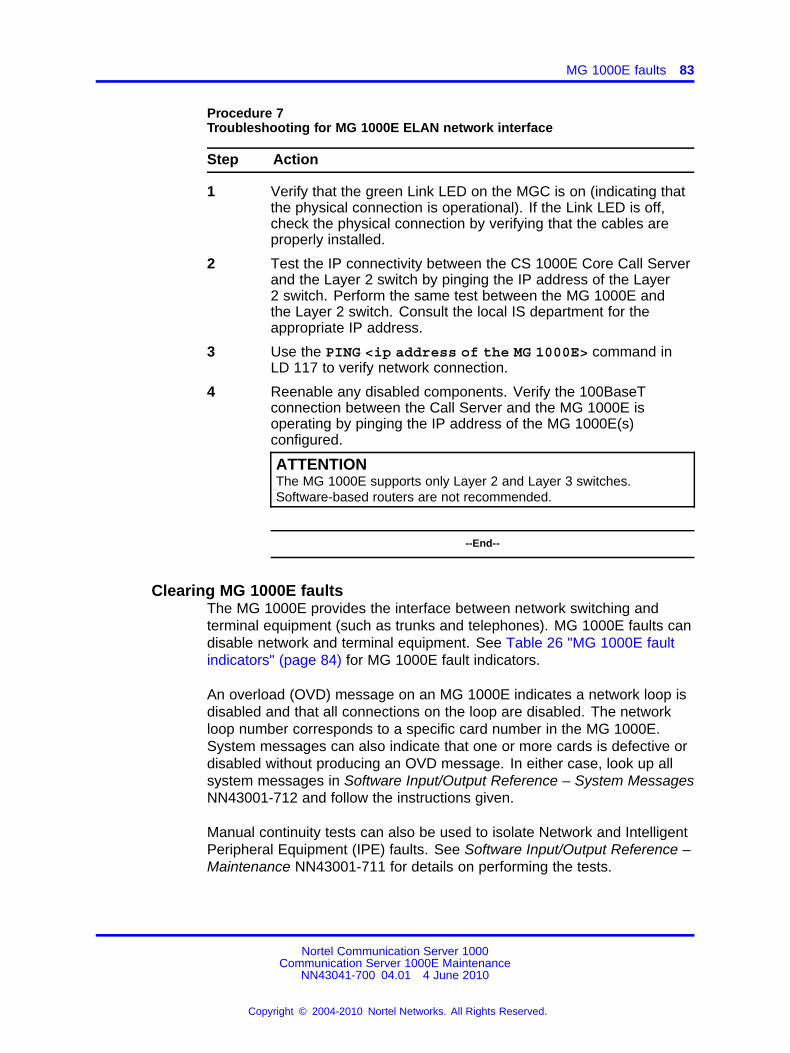
MG 1000E faults 83
Procedure 7Troubleshooting for MG 1000E ELAN network interface
Step Action
1 Verify that the green Link LED on the MGC is on (indicating thatthe physical connection is operational). If the Link LED is off,check the physical connection by verifying that the cables areproperly installed.
2 Test the IP connectivity between the CS 1000E Core Call Serverand the Layer 2 switch by pinging the IP address of the Layer2 switch. Perform the same test between the MG 1000E andthe Layer 2 switch. Consult the local IS department for theappropriate IP address.
3 Use the PING <ip address of the MG 1000E> command inLD 117 to verify network connection.
4 Reenable any disabled components. Verify the 100BaseTconnection between the Call Server and the MG 1000E isoperating by pinging the IP address of the MG 1000E(s)configured.
ATTENTIONThe MG 1000E supports only Layer 2 and Layer 3 switches.Software-based routers are not recommended.
--End--
Clearing MG 1000E faultsThe MG 1000E provides the interface between network switching andterminal equipment (such as trunks and telephones). MG 1000E faults candisable network and terminal equipment. See Table 26 "MG 1000E faultindicators" (page 84) for MG 1000E fault indicators.
An overload (OVD) message on an MG 1000E indicates a network loop isdisabled and that all connections on the loop are disabled. The networkloop number corresponds to a specific card number in the MG 1000E.System messages can also indicate that one or more cards is defective ordisabled without producing an OVD message. In either case, look up allsystem messages in Software Input/Output Reference – System MessagesNN43001-712 and follow the instructions given.
Manual continuity tests can also be used to isolate Network and IntelligentPeripheral Equipment (IPE) faults. See Software Input/Output Reference –Maintenance NN43001-711 for details on performing the tests.
Nortel Communication Server 1000Communication Server 1000E Maintenance
NN43041-700 04.01 4 June 2010
Copyright © 2004-2010 Nortel Networks. All Rights Reserved.
.
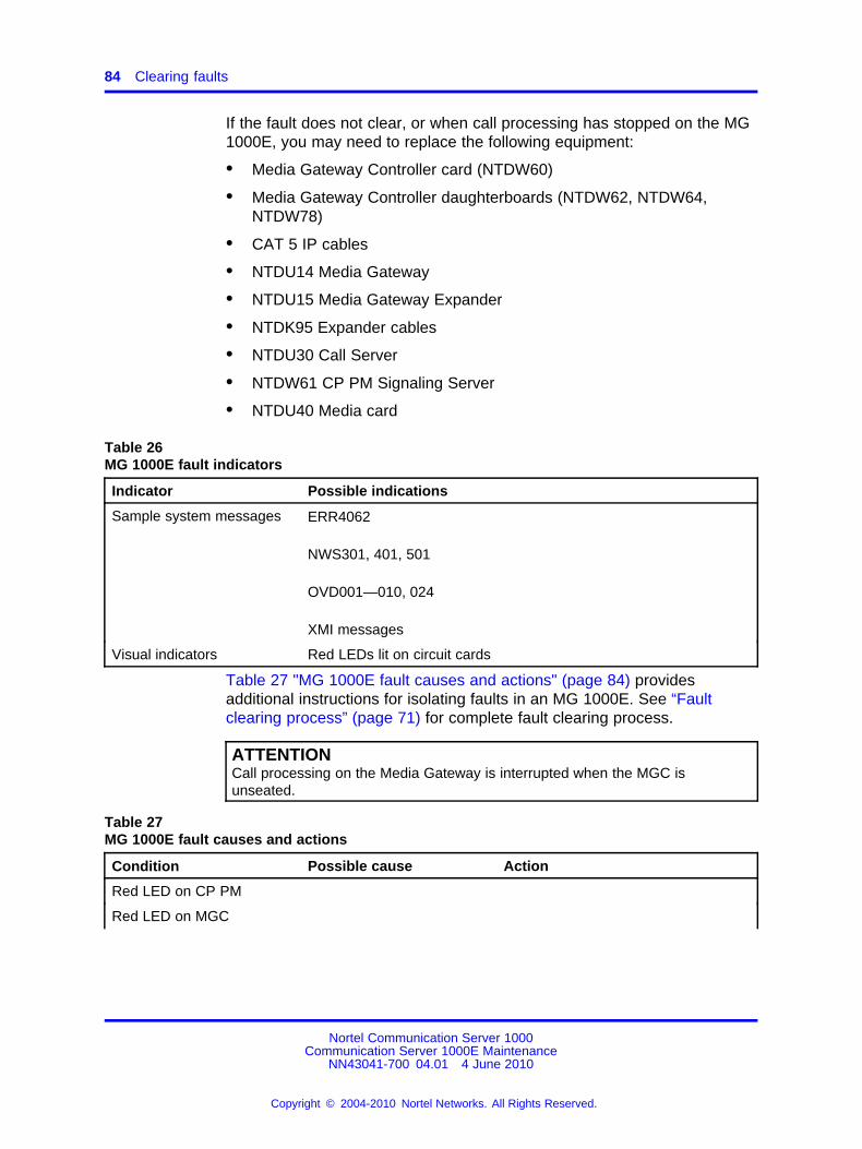
84 Clearing faults
If the fault does not clear, or when call processing has stopped on the MG1000E, you may need to replace the following equipment:
• Media Gateway Controller card (NTDW60)
• Media Gateway Controller daughterboards (NTDW62, NTDW64,NTDW78)
• CAT 5 IP cables
• NTDU14 Media Gateway
• NTDU15 Media Gateway Expander
• NTDK95 Expander cables
• NTDU30 Call Server
• NTDW61 CP PM Signaling Server
• NTDU40 Media card
Table 26MG 1000E fault indicators
Indicator Possible indications
Sample system messages ERR4062
NWS301, 401, 501
OVD001—010, 024
XMI messages
Visual indicators Red LEDs lit on circuit cards
Table 27 "MG 1000E fault causes and actions" (page 84) providesadditional instructions for isolating faults in an MG 1000E. See “Faultclearing process” (page 71) for complete fault clearing process.
ATTENTIONCall processing on the Media Gateway is interrupted when the MGC isunseated.
Table 27MG 1000E fault causes and actions
Condition Possible cause Action
Red LED on CP PM
Red LED on MGC
Nortel Communication Server 1000Communication Server 1000E Maintenance
NN43041-700 04.01 4 June 2010
Copyright © 2004-2010 Nortel Networks. All Rights Reserved.
.
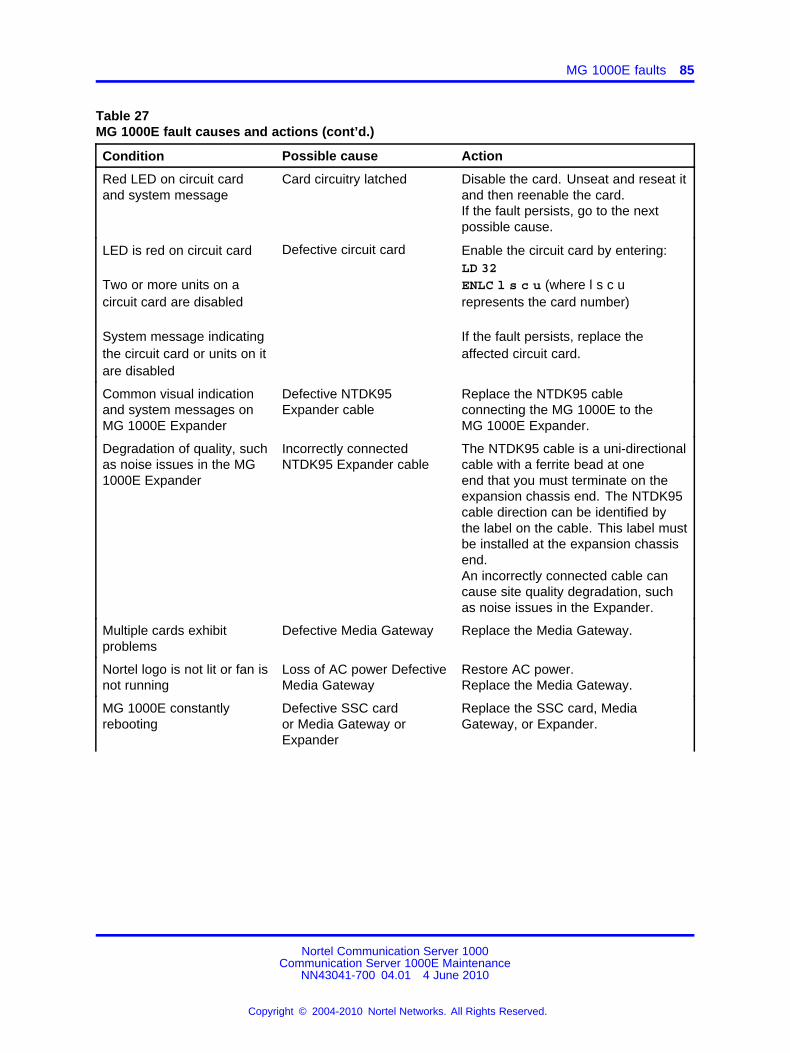
MG 1000E faults 85
Table 27MG 1000E fault causes and actions (cont’d.)
Condition Possible cause Action
Red LED on circuit cardand system message
Card circuitry latched Disable the card. Unseat and reseat itand then reenable the card.If the fault persists, go to the nextpossible cause.
LED is red on circuit card
Two or more units on acircuit card are disabled
System message indicatingthe circuit card or units on itare disabled
Defective circuit card Enable the circuit card by entering:LD 32ENLC l s c u (where l s c urepresents the card number)
If the fault persists, replace theaffected circuit card.
Common visual indicationand system messages onMG 1000E Expander
Defective NTDK95Expander cable
Replace the NTDK95 cableconnecting the MG 1000E to theMG 1000E Expander.
Degradation of quality, suchas noise issues in the MG1000E Expander
Incorrectly connectedNTDK95 Expander cable
The NTDK95 cable is a uni-directionalcable with a ferrite bead at oneend that you must terminate on theexpansion chassis end. The NTDK95cable direction can be identified bythe label on the cable. This label mustbe installed at the expansion chassisend.An incorrectly connected cable cancause site quality degradation, suchas noise issues in the Expander.
Multiple cards exhibitproblems
Defective Media Gateway Replace the Media Gateway.
Nortel logo is not lit or fan isnot running
Loss of AC power DefectiveMedia Gateway
Restore AC power.Replace the Media Gateway.
MG 1000E constantlyrebooting
Defective SSC cardor Media Gateway orExpander
Replace the SSC card, MediaGateway, or Expander.
Nortel Communication Server 1000Communication Server 1000E Maintenance
NN43041-700 04.01 4 June 2010
Copyright © 2004-2010 Nortel Networks. All Rights Reserved.
.
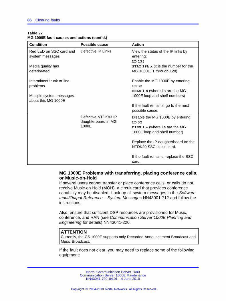
86 Clearing faults
Table 27MG 1000E fault causes and actions (cont’d.)
Condition Possible cause Action
Red LED on SSC card andsystem messages
Media quality hasdeteriorated
Intermittent trunk or lineproblems
Multiple system messagesabout this MG 1000E
Defective IP Links View the status of the IP links byentering:LD 135STAT IPL x (x is the number for theMG 1000E, 1 through 128)
Enable the MG 1000E by entering:LD 32ENLS l s (where l s are the MG1000E loop and shelf numbers)
If the fault remains, go to the nextpossible cause.
Defective NTDK83 IPdaughterboard in MG1000E
Disable the MG 1000E by entering:LD 32DISS l s (where l s are the MG1000E loop and shelf number)
Replace the IP daughterboard on theNTDK20 SSC circuit card.
If the fault remains, replace the SSCcard.
MG 1000E Problems with transferring, placing conference calls,or Music-on-HoldIf several users cannot transfer or place conference calls, or calls do notreceive Music-on-Hold (MOH), a circuit card that provides conferencecapability may be disabled. Look up all system messages in the SoftwareInput/Output Reference – System Messages NN43001-712 and follow theinstructions.
Also, ensure that sufficient DSP resources are provisioned for Music,conference, and RAN (see Communication Server 1000E Planning andEngineering for details) NN43041-220.
ATTENTIONCurrently, the CS 1000E supports only Recorded Announcement Broadcast andMusic Broadcast.
If the fault does not clear, you may need to replace some of the followingequipment:
Nortel Communication Server 1000Communication Server 1000E Maintenance
NN43041-700 04.01 4 June 2010
Copyright © 2004-2010 Nortel Networks. All Rights Reserved.
.
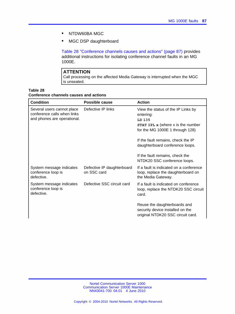
MG 1000E faults 87
• NTDW60BA MGC
• MGC DSP daughterboard
Table 28 "Conference channels causes and actions" (page 87) providesadditional instructions for isolating conference channel faults in an MG1000E.
ATTENTIONCall processing on the affected Media Gateway is interrupted when the MGCis unseated.
Table 28Conference channels causes and actions
Condition Possible cause Action
Several users cannot placeconference calls when linksand phones are operational.
Defective IP links View the status of the IP Links byentering:LD 135STAT IPL x (where x is the numberfor the MG 1000E 1 through 128)
If the fault remains, check the IPdaughterboard conference loops.
If the fault remains, check theNTDK20 SSC conference loops.
System message indicatesconference loop isdefective.
Defective IP daughterboardon SSC card
If a fault is indicated on a conferenceloop, replace the daughterboard onthe Media Gateway.
System message indicatesconference loop isdefective.
Defective SSC circuit card If a fault is indicated on conferenceloop, replace the NTDK20 SSC circuitcard.
Reuse the daughterboards andsecurity device installed on theoriginal NTDK20 SSC circuit card.
Nortel Communication Server 1000Communication Server 1000E Maintenance
NN43041-700 04.01 4 June 2010
Copyright © 2004-2010 Nortel Networks. All Rights Reserved.
.
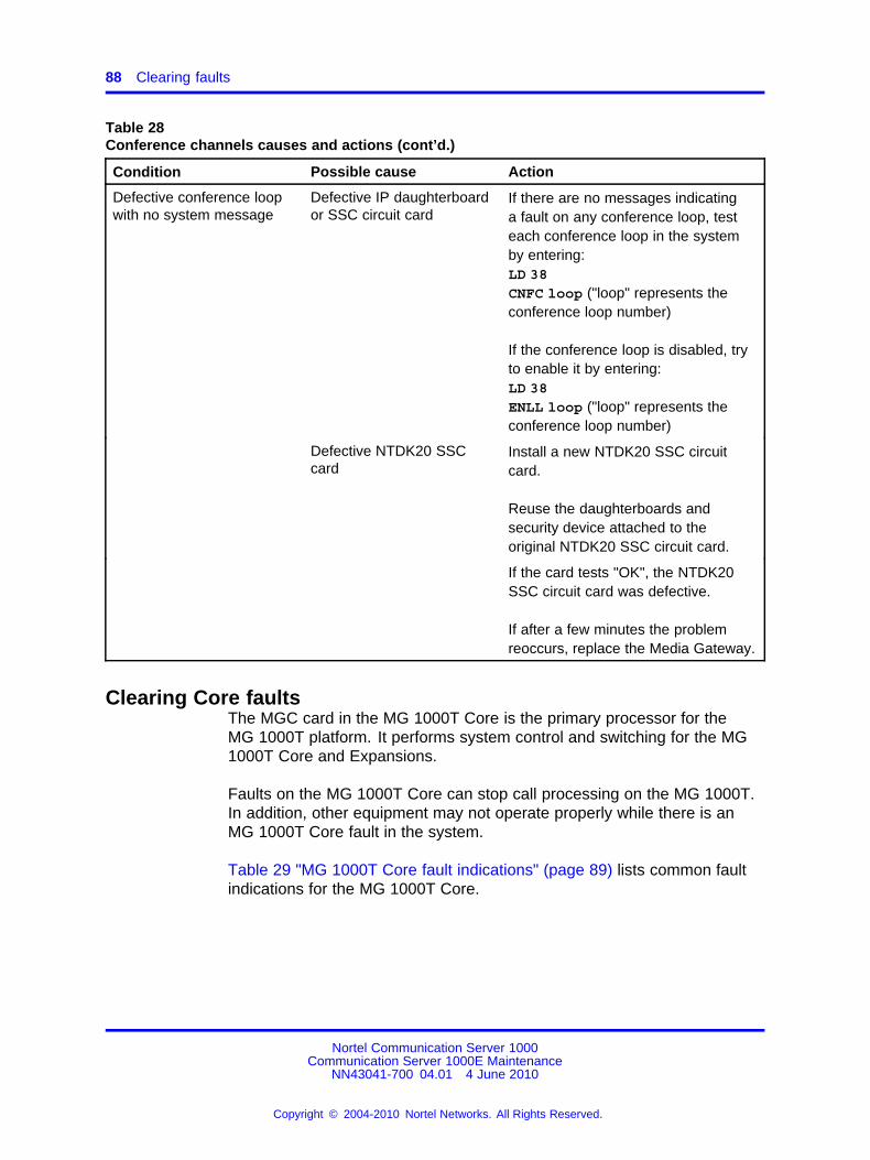
88 Clearing faults
Table 28Conference channels causes and actions (cont’d.)
Condition Possible cause Action
Defective conference loopwith no system message
Defective IP daughterboardor SSC circuit card
If there are no messages indicatinga fault on any conference loop, testeach conference loop in the systemby entering:LD 38CNFC loop ("loop" represents theconference loop number)
If the conference loop is disabled, tryto enable it by entering:LD 38ENLL loop ("loop" represents theconference loop number)
Defective NTDK20 SSCcard
Install a new NTDK20 SSC circuitcard.
Reuse the daughterboards andsecurity device attached to theoriginal NTDK20 SSC circuit card.
If the card tests "OK", the NTDK20SSC circuit card was defective.
If after a few minutes the problemreoccurs, replace the Media Gateway.
Clearing Core faultsThe MGC card in the MG 1000T Core is the primary processor for theMG 1000T platform. It performs system control and switching for the MG1000T Core and Expansions.
Faults on the MG 1000T Core can stop call processing on the MG 1000T.In addition, other equipment may not operate properly while there is anMG 1000T Core fault in the system.
Table 29 "MG 1000T Core fault indications" (page 89) lists common faultindications for the MG 1000T Core.
Nortel Communication Server 1000Communication Server 1000E Maintenance
NN43041-700 04.01 4 June 2010
Copyright © 2004-2010 Nortel Networks. All Rights Reserved.
.
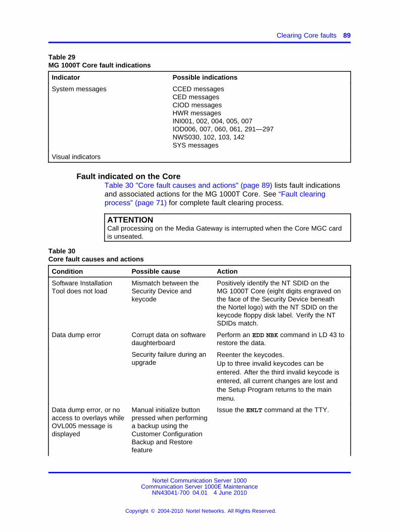
Clearing Core faults 89
Table 29MG 1000T Core fault indications
Indicator Possible indications
System messages CCED messagesCED messagesCIOD messagesHWR messagesINI001, 002, 004, 005, 007IOD006, 007, 060, 061, 291—297NWS030, 102, 103, 142SYS messages
Visual indicators
Fault indicated on the CoreTable 30 "Core fault causes and actions" (page 89) lists fault indicationsand associated actions for the MG 1000T Core. See “Fault clearingprocess” (page 71) for complete fault clearing process.
ATTENTIONCall processing on the Media Gateway is interrupted when the Core MGC cardis unseated.
Table 30Core fault causes and actions
Condition Possible cause Action
Software InstallationTool does not load
Mismatch between theSecurity Device andkeycode
Positively identify the NT SDID on theMG 1000T Core (eight digits engraved onthe face of the Security Device beneaththe Nortel logo) with the NT SDID on thekeycode floppy disk label. Verify the NTSDIDs match.
Data dump error Corrupt data on softwaredaughterboard
Perform an EDD NBK command in LD 43 torestore the data.
Security failure during anupgrade
Reenter the keycodes.Up to three invalid keycodes can beentered. After the third invalid keycode isentered, all current changes are lost andthe Setup Program returns to the mainmenu.
Data dump error, or noaccess to overlays whileOVL005 message isdisplayed
Manual initialize buttonpressed when performinga backup using theCustomer ConfigurationBackup and Restorefeature
Issue the ENLT command at the TTY.
Nortel Communication Server 1000Communication Server 1000E Maintenance
NN43041-700 04.01 4 June 2010
Copyright © 2004-2010 Nortel Networks. All Rights Reserved.
.
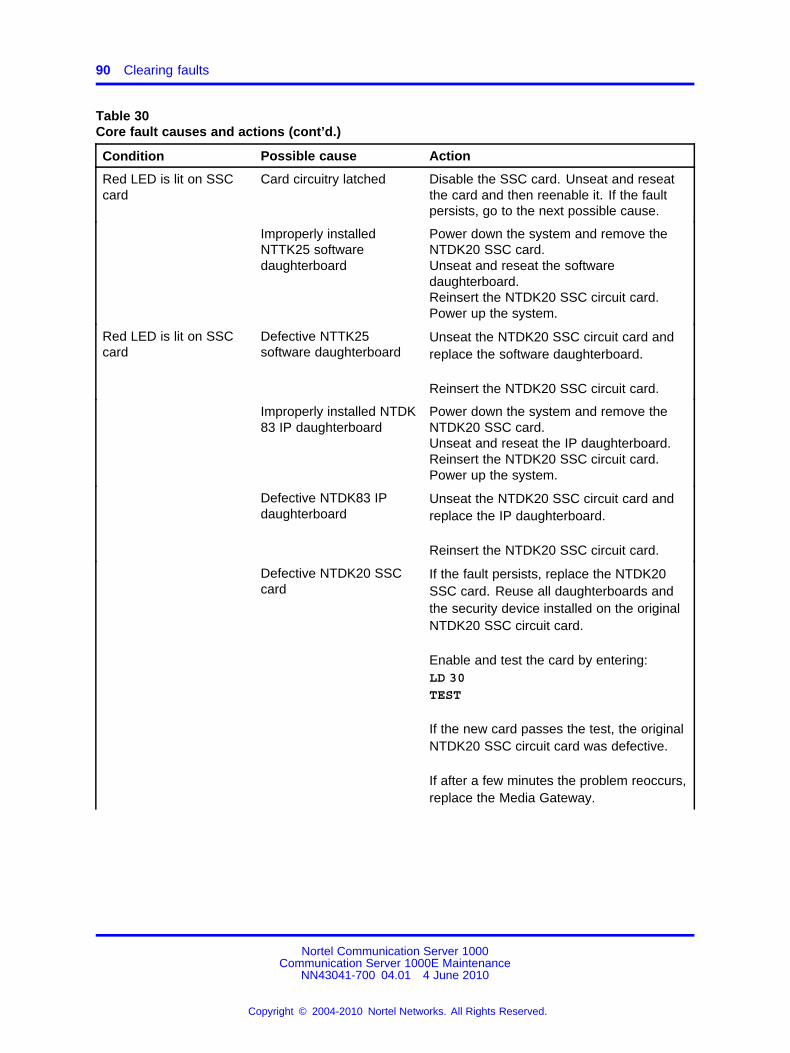
90 Clearing faults
Table 30Core fault causes and actions (cont’d.)
Condition Possible cause Action
Red LED is lit on SSCcard
Card circuitry latched Disable the SSC card. Unseat and reseatthe card and then reenable it. If the faultpersists, go to the next possible cause.
Improperly installedNTTK25 softwaredaughterboard
Power down the system and remove theNTDK20 SSC card.Unseat and reseat the softwaredaughterboard.Reinsert the NTDK20 SSC circuit card.Power up the system.
Red LED is lit on SSCcard
Defective NTTK25software daughterboard
Unseat the NTDK20 SSC circuit card andreplace the software daughterboard.
Reinsert the NTDK20 SSC circuit card.
Improperly installed NTDK83 IP daughterboard
Power down the system and remove theNTDK20 SSC card.Unseat and reseat the IP daughterboard.Reinsert the NTDK20 SSC circuit card.Power up the system.
Defective NTDK83 IPdaughterboard
Unseat the NTDK20 SSC circuit card andreplace the IP daughterboard.
Reinsert the NTDK20 SSC circuit card.
Defective NTDK20 SSCcard
If the fault persists, replace the NTDK20SSC card. Reuse all daughterboards andthe security device installed on the originalNTDK20 SSC circuit card.
Enable and test the card by entering:LD 30TEST
If the new card passes the test, the originalNTDK20 SSC circuit card was defective.
If after a few minutes the problem reoccurs,replace the Media Gateway.
Nortel Communication Server 1000Communication Server 1000E Maintenance
NN43041-700 04.01 4 June 2010
Copyright © 2004-2010 Nortel Networks. All Rights Reserved.
.
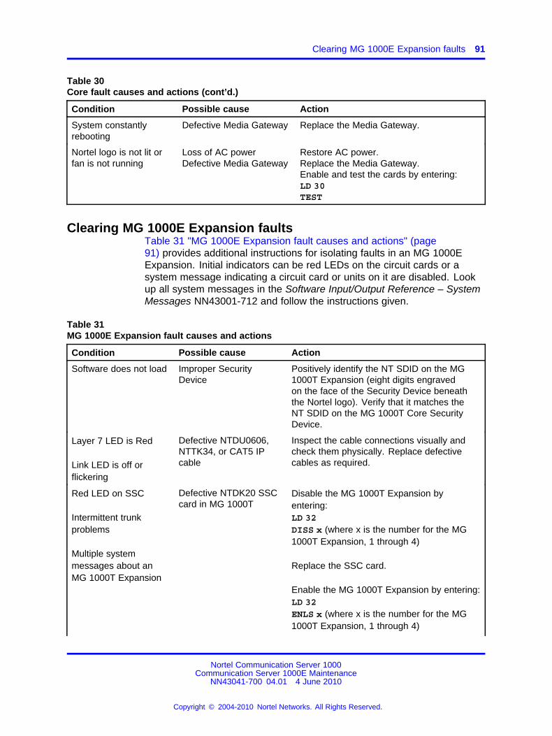
Clearing MG 1000E Expansion faults 91
Table 30Core fault causes and actions (cont’d.)
Condition Possible cause Action
System constantlyrebooting
Defective Media Gateway Replace the Media Gateway.
Nortel logo is not lit orfan is not running
Loss of AC powerDefective Media Gateway
Restore AC power.Replace the Media Gateway.Enable and test the cards by entering:LD 30TEST
Clearing MG 1000E Expansion faultsTable 31 "MG 1000E Expansion fault causes and actions" (page91) provides additional instructions for isolating faults in an MG 1000EExpansion. Initial indicators can be red LEDs on the circuit cards or asystem message indicating a circuit card or units on it are disabled. Lookup all system messages in the Software Input/Output Reference – SystemMessages NN43001-712 and follow the instructions given.
Table 31MG 1000E Expansion fault causes and actions
Condition Possible cause Action
Software does not load Improper SecurityDevice
Positively identify the NT SDID on the MG1000T Expansion (eight digits engravedon the face of the Security Device beneaththe Nortel logo). Verify that it matches theNT SDID on the MG 1000T Core SecurityDevice.
Layer 7 LED is Red
Link LED is off orflickering
Defective NTDU0606,NTTK34, or CAT5 IPcable
Inspect the cable connections visually andcheck them physically. Replace defectivecables as required.
Red LED on SSC
Intermittent trunkproblems
Multiple systemmessages about anMG 1000T Expansion
Defective NTDK20 SSCcard in MG 1000T
Disable the MG 1000T Expansion byentering:LD 32DISS x (where x is the number for the MG1000T Expansion, 1 through 4)
Replace the SSC card.
Enable the MG 1000T Expansion by entering:LD 32ENLS x (where x is the number for the MG1000T Expansion, 1 through 4)
Nortel Communication Server 1000Communication Server 1000E Maintenance
NN43041-700 04.01 4 June 2010
Copyright © 2004-2010 Nortel Networks. All Rights Reserved.
.
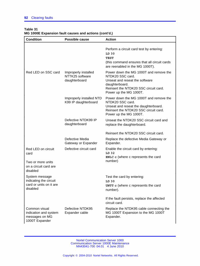
92 Clearing faults
Table 31MG 1000E Expansion fault causes and actions (cont’d.)
Condition Possible cause Action
Perform a circuit card test by entering:LD 30TEST(this command ensures that all circuit cardsare reenabled in the MG 1000T).
Red LED on SSC card Improperly installedNTTK25 softwaredaughterboard
Power down the MG 1000T and remove theNTDK20 SSC card.Unseat and reseat the softwaredaughterboard.Reinsert the NTDK20 SSC circuit card.Power up the MG 1000T.
Improperly installed NTDK99 IP daughterboard
Power down the MG 1000T and remove theNTDK20 SSC card.Unseat and reseat the daughterboard.Reinsert the NTDK20 SSC circuit card.Power up the MG 1000T.
Defective NTDK99 IPdaughterboard
Unseat the NTDK20 SSC circuit card andreplace the daughterboard.
Reinsert the NTDK20 SSC circuit card.
Defective MediaGateway or Expander
Replace the defective Media Gateway orExpander.
Red LED on circuitcard
Two or more unitson a circuit card aredisabled
Defective circuit card Enable the circuit card by entering:LD 32ENLC c (where c represents the cardnumber)
System messageindicating the circuitcard or units on it aredisabled
Test the card by entering:LD 30UNTT c (where c represents the cardnumber).
If the fault persists, replace the affectedcircuit card.
Common visualindication and systemmessages on MG1000T Expander
Defective NTDK95Expander cable
Replace the NTDK95 cable connecting theMG 1000T Expansion to the MG 1000TExpander.
Nortel Communication Server 1000Communication Server 1000E Maintenance
NN43041-700 04.01 4 June 2010
Copyright © 2004-2010 Nortel Networks. All Rights Reserved.
.
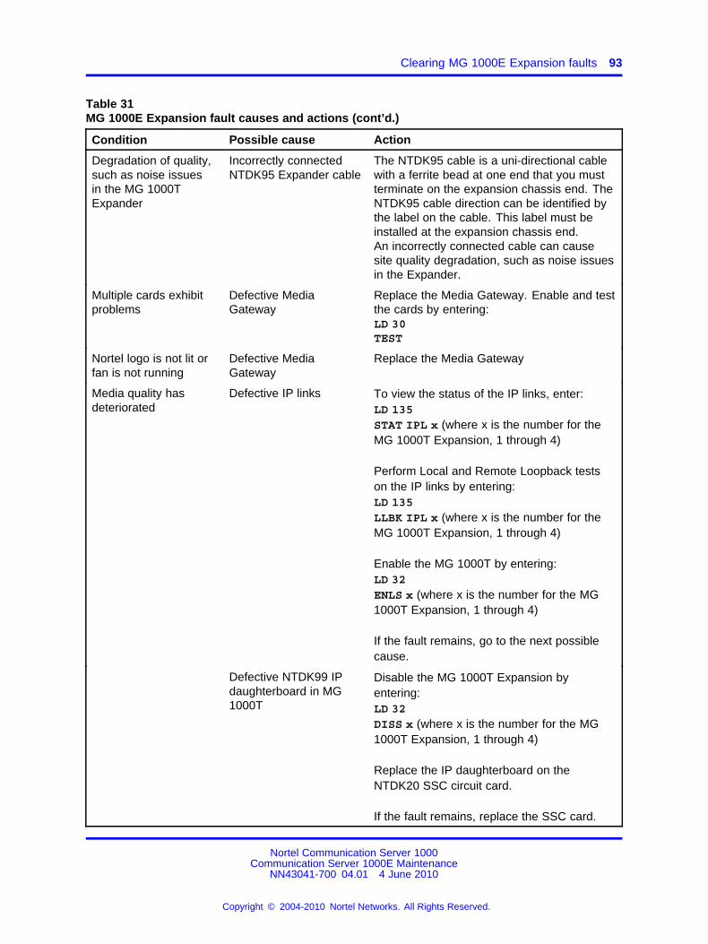
Clearing MG 1000E Expansion faults 93
Table 31MG 1000E Expansion fault causes and actions (cont’d.)
Condition Possible cause Action
Degradation of quality,such as noise issuesin the MG 1000TExpander
Incorrectly connectedNTDK95 Expander cable
The NTDK95 cable is a uni-directional cablewith a ferrite bead at one end that you mustterminate on the expansion chassis end. TheNTDK95 cable direction can be identified bythe label on the cable. This label must beinstalled at the expansion chassis end.An incorrectly connected cable can causesite quality degradation, such as noise issuesin the Expander.
Multiple cards exhibitproblems
Defective MediaGateway
Replace the Media Gateway. Enable and testthe cards by entering:LD 30TEST
Nortel logo is not lit orfan is not running
Defective MediaGateway
Replace the Media Gateway
Media quality hasdeteriorated
Defective IP links To view the status of the IP links, enter:LD 135STAT IPL x (where x is the number for theMG 1000T Expansion, 1 through 4)
Perform Local and Remote Loopback testson the IP links by entering:LD 135LLBK IPL x (where x is the number for theMG 1000T Expansion, 1 through 4)
Enable the MG 1000T by entering:LD 32ENLS x (where x is the number for the MG1000T Expansion, 1 through 4)
If the fault remains, go to the next possiblecause.
Defective NTDK99 IPdaughterboard in MG1000T
Disable the MG 1000T Expansion byentering:LD 32DISS x (where x is the number for the MG1000T Expansion, 1 through 4)
Replace the IP daughterboard on theNTDK20 SSC circuit card.
If the fault remains, replace the SSC card.
Nortel Communication Server 1000Communication Server 1000E Maintenance
NN43041-700 04.01 4 June 2010
Copyright © 2004-2010 Nortel Networks. All Rights Reserved.
.
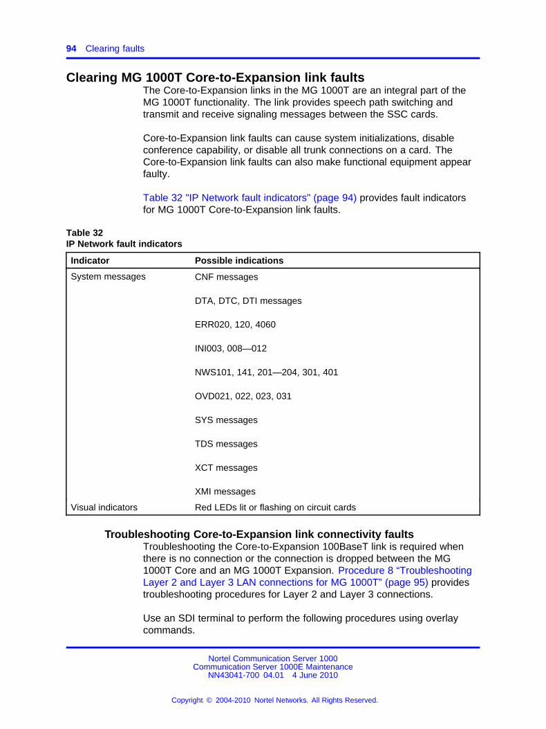
94 Clearing faults
Clearing MG 1000T Core-to-Expansion link faultsThe Core-to-Expansion links in the MG 1000T are an integral part of theMG 1000T functionality. The link provides speech path switching andtransmit and receive signaling messages between the SSC cards.
Core-to-Expansion link faults can cause system initializations, disableconference capability, or disable all trunk connections on a card. TheCore-to-Expansion link faults can also make functional equipment appearfaulty.
Table 32 "IP Network fault indicators" (page 94) provides fault indicatorsfor MG 1000T Core-to-Expansion link faults.
Table 32IP Network fault indicators
Indicator Possible indications
System messages CNF messages
DTA, DTC, DTI messages
ERR020, 120, 4060
INI003, 008—012
NWS101, 141, 201—204, 301, 401
OVD021, 022, 023, 031
SYS messages
TDS messages
XCT messages
XMI messages
Visual indicators Red LEDs lit or flashing on circuit cards
Troubleshooting Core-to-Expansion link connectivity faultsTroubleshooting the Core-to-Expansion 100BaseT link is required whenthere is no connection or the connection is dropped between the MG1000T Core and an MG 1000T Expansion. Procedure 8 “TroubleshootingLayer 2 and Layer 3 LAN connections for MG 1000T” (page 95) providestroubleshooting procedures for Layer 2 and Layer 3 connections.
Use an SDI terminal to perform the following procedures using overlaycommands.
Nortel Communication Server 1000Communication Server 1000E Maintenance
NN43041-700 04.01 4 June 2010
Copyright © 2004-2010 Nortel Networks. All Rights Reserved.
.
Monitoring 100BaseT link voice Quality of Service 95
Layer 2 and Layer 3 LAN connectionsThe MG 1000T platform supports only Layer 2 and Layer 3 switches.Software routers are not recommended. To troubleshoot for Layer 2 andLayer 3 LAN connection, follow the steps in Procedure 8 “TroubleshootingLayer 2 and Layer 3 LAN connections for MG 1000T” (page 95).
Procedure 8Troubleshooting Layer 2 and Layer 3 LAN connections for MG 1000T
Step Action
1 Verify that the green Link LED on the daughterboard in theMGCis on (this indicates that the physical connection isfunctioning). If the Link LED is off, check the physical connectionby verifying that the daughterboard and cables are properlyinstalled.
2 Test the LAN connectivity between the Call server and the Layer2/3 switch by pinging the IP address of the Layer 2/3 switch.Perform the same test between the MG 1000E and the Layer2/3 switch. Consult the local IS department for the appropriateIP address.
3 To disable the link for testing, in LD 32, enter DISS <n> (where n= IP daughterboard port#).
4 To test the signaling and voice path of the daughterboard, inLD 135, enter LLBK <link #>. If the card fails the LLBK test,replace the IP daughterboard.
5 In LD 117, enter PING <ip address of the MG 1000TExpansion> to verify the network connection.
6 Re-enable any disabled components. Verify that the 100BaseTconnection between the MG 1000T Core and the MG 1000TExpansion is operating by pinging the IP address of the MG1000T Expansion(s) configured.
--End--
Monitoring 100BaseT link voice Quality of ServiceBehavioral characteristics of the network are dependent on factors likeRound Trip Delay (RTD), queueing delay in the intermediate nodes, packetloss, and available bandwidth.
The service level of each IP link is measured and maintained on the CallServer for the operation of the MG 1000Es. Information for latency andpacket loss is collected from the hardware and processed. Based onsystem-configured thresholds, the level of service is derived and reportedautomatically or when the technician requests a report with the PRT QOS
Nortel Communication Server 1000Communication Server 1000E Maintenance
NN43041-700 04.01 4 June 2010
Copyright © 2004-2010 Nortel Networks. All Rights Reserved.
.
96 Clearing faults
<cab#> command in LD 117. See Software Input/Output AdministrationNN43001-611 and Software Input/Output Reference – MaintenanceNN43001-711.
Data Network Ratings (Excellent, Good, Fair, and Poor) are calculatedalong with the actual parameter values for the network delay. See Table33 "Campus data network voice quality measurements" (page 96) for theData Network Ratings parameters for specific values of Packet DelayVariation (PDV) and packet loss.
Table 33Campus data network voice quality measurements
PDV Max7.8 ms
PDV Min0.5 ms Packet loss
Excellent <5 ms <12 ms < 0.5%
Good 5 - 25 ms 12 - 32 ms 0.5 - 1%
Fair 25 - 45 ms 32 - 52 ms 1 - 1.5%
Poor >45 ms >52 ms > 1.5%
The values presented in Table 33 "Campus data network voice qualitymeasurements" (page 96) assume that there is no echo cancellationmechanism and no particular mechanism for recovering lost packets.
The command PRT PDV <cab#> in LD 117 displays both the current sizeof the PDV buffer and the number of PDV underflows.
In addition, a warning message is printed when a parameter threshold or acombination of thresholds is reached. You cannot configure the thresholds.
In LD 117, the command CHG PDV <port#> <delay> is used to configurea PDV buffer size for each link basis. The <delay> parameter can takevalues from 0.5 ms to 8 ms. This value should be initially tested at defaultsettings. Increase the <delay> parameter value by 0.5 ms increments ifan unacceptable level of voice quality is experienced ("pops and clicks").Decrease this value if an echo is experienced. The goal is to operate withthe smallest buffer possible.
The PDV buffer size for each IP connection is configured at the Call Serverfor the MG 1000Es.
ATTENTIONSystems must meet the minimum data networking requirements fromConverging the Data Network with VoIP Fundamentals NN43001-260.
Nortel Communication Server 1000Communication Server 1000E Maintenance
NN43041-700 04.01 4 June 2010
Copyright © 2004-2010 Nortel Networks. All Rights Reserved.
.
Clearing trunk faults 97
Clearing trunk faultsThis section deals with trunk faults on either the MG 1000E or MG 1000T.Trunk circuit cards provide the interface between the system and CentralOffice (CO) trunks, or between PBXs. The maintenance telephone can beused to test trunks. Two types of trunk cards are considered:
• E&M Trunk: provides four trunk units, each of which can be connectedto a trunk configured to operate as one of the following:
— E&M signaling trunk
— Two-wire Tie trunk
— Four-wire Tie trunk
— Paging trunk
• Universal Trunk: provides eight trunk units, each of which can beconnected to a trunk configured to operate as one of the following:
— CO trunk
— Direct Inward Dialing (DID) trunk
— Two-way Tie, Dial Repeating (2DR)
— Two-way Tie, Outgoing Automatic Incoming Dial (OAID) trunk
— Recorded Announcement (RAN) trunk
— Music trunk
— Paging trunk
Trunk faults can cause problems (such as noise) on outside calls and cankeep calls from entering or leaving the system.
Fault clearing procedures using an SDI terminalSee Table 34 "Trunk fault indicators" (page 97) for trunk fault indicators.
Table 34Trunk fault indicators
Indicator Possible indications
System messages ERR090, 220, 270 OVD001—010TRK messages
Visual indicators Red LED lit on trunk circuit card
Trunk cannot make or receive callsA user cannot make or receive calls over a trunk. An OVD systemmessage may be received, indicating that this trunk has been disabled.Look up all system messages in the Software Input/Output Reference –System Messages NN43001-712 and follow the instructions.
Nortel Communication Server 1000Communication Server 1000E Maintenance
NN43041-700 04.01 4 June 2010
Copyright © 2004-2010 Nortel Networks. All Rights Reserved.
.
98 Clearing faults
If the fault does not clear, manual continuity tests can be used to isolatefaults to peripheral equipment, such as E&M or Universal Trunk circuitcards. See Software Input/Output Reference – MaintenanceNN43001-711for details on performing the tests in LD 30.
Trunk connections from the main frame to the trunk cards can be checkedwith a butt telephone or test telephone. Check the trunk wiring at the entrypoint for dial tone and progress toward the Media Gateway.
Constantly observe and look up system messages as you replaceequipment.
You may need to replace:
• E&M Trunk circuit card: NT8D15
• Universal Trunk circuit card: NT8D14
• any other trunk circuit card
• NTAK03 TDS/DTR circuit card
• trunk equipment (such as music source or paging equipment)
Table 35 "Trunk cannot make or receive calls(OVD message may bereceived)" (page 98) provides additional instructions for isolating trunkfaults in an MG 1000E.
Table 35Trunk cannot make or receive calls(OVD message may be received)
Possible cause Action
Excessive traffic in thesystem
Additional trunk circuit cards may be required to handle the traffic in thesystem.
Defective trunk circuitcard
If the indicated circuit card is an E&M or Universal Trunk circuit card,hardware-disable it and then reenable to initiate a self-test.
If the test fails, replace the circuit card. If the test passes, disconnect thewiring between the circuit card and the cross-connect terminal.
Nortel Communication Server 1000Communication Server 1000E Maintenance
NN43041-700 04.01 4 June 2010
Copyright © 2004-2010 Nortel Networks. All Rights Reserved.
.
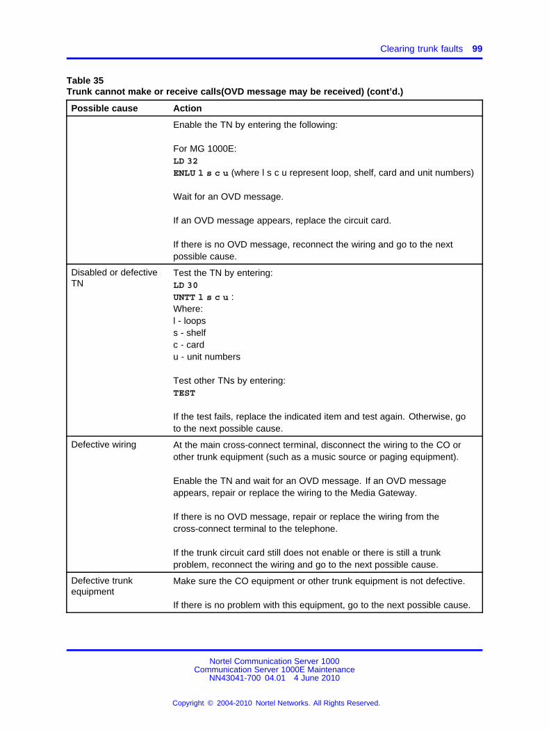
Clearing trunk faults 99
Table 35Trunk cannot make or receive calls(OVD message may be received) (cont’d.)
Possible cause Action
Enable the TN by entering the following:
For MG 1000E:LD 32ENLU l s c u (where l s c u represent loop, shelf, card and unit numbers)
Wait for an OVD message.
If an OVD message appears, replace the circuit card.
If there is no OVD message, reconnect the wiring and go to the nextpossible cause.
Disabled or defectiveTN
Test the TN by entering:LD 30UNTT l s c u :Where:l - loopss - shelfc - cardu - unit numbers
Test other TNs by entering:TEST
If the test fails, replace the indicated item and test again. Otherwise, goto the next possible cause.
Defective wiring At the main cross-connect terminal, disconnect the wiring to the CO orother trunk equipment (such as a music source or paging equipment).
Enable the TN and wait for an OVD message. If an OVD messageappears, repair or replace the wiring to the Media Gateway.
If there is no OVD message, repair or replace the wiring from thecross-connect terminal to the telephone.
If the trunk circuit card still does not enable or there is still a trunkproblem, reconnect the wiring and go to the next possible cause.
Defective trunkequipment
Make sure the CO equipment or other trunk equipment is not defective.
If there is no problem with this equipment, go to the next possible cause.
Nortel Communication Server 1000Communication Server 1000E Maintenance
NN43041-700 04.01 4 June 2010
Copyright © 2004-2010 Nortel Networks. All Rights Reserved.
.
100 Clearing faults
Clearing Terminal Server faultsOne potential fault that can occur with the MRV Terminal Server isdatabase corruption. When there is a database fault, all Terminal ServerLEDs flash and the console port does not respond.
To correct this fault, configure all parameters to factory default asdescribed in MRV procedures.
ATTENTIONTo prevent database corruption in the MRV Terminal Server, never removethe Flash card or power down the Terminal Server while the Flash card LEDis illuminated.
Clearing IP Phone faultsFor IP Phone fault clearing procedures, see IP Phones FundamentalsNN43001-368 and IP Line Fundamentals.
Nortel Communication Server 1000Communication Server 1000E Maintenance
NN43041-700 04.01 4 June 2010
Copyright © 2004-2010 Nortel Networks. All Rights Reserved.
.
101.
Database management
ContentsThis section contains the following topics:
• “Tools to backup and restore customer databases” (page 101)
• “Equipment Data Dump” (page 102)
• “Customer Configuration Backup and Restore” (page 102)
• “Coresilient server Backup” (page 107)
• “OAM Backup” (page 107)
Tools to backup and restore customer databasesElement Manager provides access to Call Server backup and restorefunctions. See “Call Server backup, data dump, and restore” (page 157).
LD 43 and LD 143 provide different methods to backup and restorecustomer data:
• LD 43: Equipment Data Dump (EDD)
— CP PIV: backs up the customer database from internal memory tothe internal drive on the SSC and to RMD (compact flash)
— CP PM: backs up the customer database from internal memory tofile (/u/ccbr/ccbr.gz) and to RMD (compact flash)
• LD 43: The BKO command copies EDD output to removable media.
• LD 143: The Archive Database Utilities program provides a way tocopy EDD output to removable media in a format organized by theuser.
• LD 143: Customer Configuration Backup and Restore (CCBR) backsup customer data to an external device over a direct serial connection.
Nortel Communication Server 1000Communication Server 1000E Maintenance
NN43041-700 04.01 4 June 2010
Copyright © 2004-2010 Nortel Networks. All Rights Reserved.
.
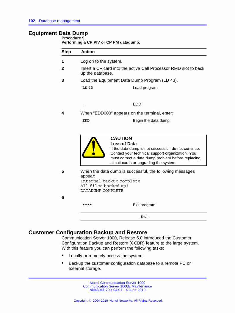
102 Database management
Equipment Data DumpProcedure 9Performing a CP PIV or CP PM datadump:
Step Action
1 Log on to the system.
2 Insert a CF card into the active Call Processor RMD slot to backup the database.
3 Load the Equipment Data Dump Program (LD 43).
LD 43 Load program
. EDD
4 When "EDD000" appears on the terminal, enter:
EDD Begin the data dump
CAUTIONLoss of DataIf the data dump is not successful, do not continue.Contact your technical support organization. Youmust correct a data dump problem before replacingcircuit cards or upgrading the system.
5 When the data dump is successful, the following messagesappear:Internal backup completeAll files backed up!DATADUMP COMPLETE
6
**** Exit program
--End--
Customer Configuration Backup and RestoreCommunication Server 1000, Release 5.0 introduced the CustomerConfiguration Backup and Restore (CCBR) feature to the large system.With this feature you can perform the following tasks:
• Locally or remotely access the system.
• Backup the customer configuration database to a remote PC orexternal storage.
Nortel Communication Server 1000Communication Server 1000E Maintenance
NN43041-700 04.01 4 June 2010
Copyright © 2004-2010 Nortel Networks. All Rights Reserved.
.
Customer Configuration Backup and Restore 103
• Restore or update the customer configuration database when thesystem is operating.
• Restore or update the customer configuration database when thesystem is not operating.
Equipment requirementsCCBR requires the following equipment:
• a computer that supports Xmodem communications protocol
Ensure that your communications package complies with the protocolspecifications described in Communication Server 1000E Installationand Commissioning . Not all Xmodem protocols are identical. Somemay not operate properly with the CCBR feature.
• modems for remote access
To remotely access the system, connect a modem to an SDI port on theMGC or on the CP PM card.
To locally access the system, connect a computer directly to an SDI porton the MGC or on the CP PM card.
Feature operationsProcedure 10Backing up the customer configuration database
Step Action
1 Log on to the system.
2 Perform a data dump using LD 43, as shown in “Equipment DataDump” (page 102).
3 Type **** to exit LD 43.
4 Type LD 143.
The system responds with the following:
CCBR000.
ATTENTIONReview Steps 5 through 7 before you proceed. If you do not performthese steps within approximately 5 minutes after you issue the XBKcommand, the system times out.
5 Type XBK.
The system responds with the following:
INFO:total packets : xxx
Nortel Communication Server 1000Communication Server 1000E Maintenance
NN43041-700 04.01 4 June 2010
Copyright © 2004-2010 Nortel Networks. All Rights Reserved.
.
104 Database management
number of retries : 0receive timeouts : 0system errors : 0unknown characters : xtransfer cancelled : 0packets received out of sequence : 0packets with corrupted sequence : 0packets failed checksum/crc check : 0incomplete packets : 0duplicate packets : 0
6 Enter a header name for the configuration data backup fileand press Enter. Enter up to 128 characters of text, includingspaces, carriage returns, and line feeds.
If you enter more than 128 characters, the system exits text entrymode and responds with R>. If you do not want to enter text,press Enter.
The system responds with R> , to indicate that it is ready tocontinue.
ATTENTIONYou must complete the next step within 2 minutes or the systemtimes out. If a timeout occurs, return to Step 5 and retype the XBKcommand.
7 To receive the configuration database file, use the Xmodemprotocol. The file arrives in binary format.
For information about receiving files, see the manual suppliedwith your communications software package.
8 Wait for the file transfer operation to end. File transfer timedepends on database size and baud rate. When the file transfercompletes successfully, the system responds as follows:
total packets : xxxnumber of retries : 0receive timeouts : 0system errors : 0unknown characters : xtransfer cancelled : 0packets received out of sequence : 0packets with corrupted sequence : 0packets failed checksum/crc check : 0incomplete packets : 0duplicate packets : 0
If the file transfer fails, the system responds as follows:
total packets : 0number of retries : 0
Nortel Communication Server 1000Communication Server 1000E Maintenance
NN43041-700 04.01 4 June 2010
Copyright © 2004-2010 Nortel Networks. All Rights Reserved.
.
Customer Configuration Backup and Restore 105
receive timeouts : xsystem errors : 0unknown characters : xxtransfer cancelled : 0packets received out of sequence : 0packets with corrupted sequence : 0packets failed checksum/crc check : 0incomplete packets : 0duplicate packets : 0ERROR from sx
The configuration database backup procedure is complete. Type**** to exit the program.
--End--
Procedure 11Restoring or updating the configuration database (system operating)
Step Action
1 Type LD 143.
2 The system responds with the following:
CCBR
3 Type XRT to begin the configuration database restore.
The system prepares to receive the database file from thecomputer and restore it to the (CP PIV) or to the Call Processor(CP PM).
4 The system responds with the following:
WAIT - - 2 MINUTESR>
WARNINGThe receiving file is erased at the start of this step.If a problem occurs during the restore procedure,do not leave the system in this state. Repeat therestore procedure. If you encounter further problems,perform an EDD to dump the current data to the SSC(CP PII and CP PIV) or to the Call Processor file (CPPM).
5 Send the backed up database file to the system using thecommunications software and the XModem protocol on thecomputer.
The system displays the character C every 3 seconds until thefile transfer is complete. The file transfer must finish before the
Nortel Communication Server 1000Communication Server 1000E Maintenance
NN43041-700 04.01 4 June 2010
Copyright © 2004-2010 Nortel Networks. All Rights Reserved.
.
106 Database management
character C appears 20 times (approximately 1 minute) to avoida system timeout.
The system site ID, n the configuration database records beingsent, is compared to the ID on the system. If the IDs do notmatch, the data is restored, but the following warning messageappears:
BKP0011 The site ID in the restored data does not matchthat of the system. This response is normal whenyou use this procedure as part of an installationprocess.
Corrective action:Ensure that the customer data file is correctand that you are not restoring the wrong file tothe system. If the file is correct, contact Norteltechnical support.
When the database restore succeeds, the system responds: OK.
6 If the database restore fails, the system sends one of thefollowing messages:
BKP0003 The received file contains invalid data.Corrective action:Check the transmitted data file to ensure that it isthe correct one.
Repeat the restore procedure using the XRTcommand. If the procedure fails again, a corruptdata file is a probability.
BKP0008 Transmission error occurred due to a timeout orexcessive line noise.Corrective action:Repeat the procedure.
7 Reboot or sysload the system.
ATTENTIONUsing the STAD commandEffective in CS 1000, Release 5.0, only users that have SEC_ADMINprivileges can change the system time and date. For moreinformation about security enhancements, see Security ManagementFundamentals (NN43001-604).
8 Reset the correct time and date:LD 2STAD (day) (month) (year) (hour) (minute) (second)
9 Check the time and date entered:TTAD
Nortel Communication Server 1000Communication Server 1000E Maintenance
NN43041-700 04.01 4 June 2010
Copyright © 2004-2010 Nortel Networks. All Rights Reserved.
.
OAM Backup 107
Customer configuration database restore is complete.To exit LD 43, type ****.
--End--
Coresilient server BackupUse the Nortel Linux Base sysbackup and sysrestore commands tobackup the network configuration information. For information about thesecommands see, Linux Platform Base and Applications Installation andCommissioning (NN43001-315).
OAM BackupThe maintenance events of OAM audit log captures all the upgrades,backups, restores and patching. After the upgrade of Linux Base, all theOAM log files and syslog.conf are restored.
Use the sysbackup command to backup the oam.log, security.log, and/etc/rsyslog.conf files.
Use the sysrestore command to restore all the OAM log files.
The upgrade time depends on the number of OAM log files. The maximumnumber of files that can be backed up and restored is 60.
Nortel Communication Server 1000Communication Server 1000E Maintenance
NN43041-700 04.01 4 June 2010
Copyright © 2004-2010 Nortel Networks. All Rights Reserved.
.

108 Database management
Nortel Communication Server 1000Communication Server 1000E Maintenance
NN43041-700 04.01 4 June 2010
Copyright © 2004-2010 Nortel Networks. All Rights Reserved.
.
109.
Replacing equipment
ContentsThis section contains the following topics:
• “Removing the MG 1000E cover” (page 110)
• “Replacing the NTDW61 CP PM Call Processor card” (page 110)
• “Replacing NTDW61 CP PM Signaling Server equipment” (page 127)
• “Replacing the NTDW60 Media Gateway Controller card” (page 131)
• “Replacing the NTDW62 or NTDW64 DSP daughterboard” (page 133)
• “Replacing the NTDW65 Voice Gateway Media Card” (page 134)
• “Replacing the NT4N39AA CP PIV Call Processor card” (page 134)
• “Replacing the NT4N48 System Utility card” (page 136)
• “Replacing the NTDU64 alarm/fan module” (page 139)
• “Replacing the NTDU65 power supply module” (page 139)
• “Accessing Media Gateway internal components” (page 142)
• “Replacing the NTAK02 SDI/DCH circuit card” (page 143)
• “Replacing the NTAK03 TDS/DTR circuit card” (page 144)
• “Replacing the NTAK79 or NTBK50 2.0 Mb PRI card” (page 144)
• “Replacing the NTAK09 1.5 Mb DTI/PRI card (PRI applications)” (page147)
• “Replacing the NTAK09, NTAK10, or NTRB21 circuit cards (DTIapplications)” (page 148)
• “Replacing equipment cards” (page 149)
• “Replacing IP daughterboards” (page 153)
ATTENTIONBack up customer databaseBefore you replace circuit cards, back up the customer database. See“Equipment Data Dump” (page 102).
Nortel Communication Server 1000Communication Server 1000E Maintenance
NN43041-700 04.01 4 June 2010
Copyright © 2004-2010 Nortel Networks. All Rights Reserved.
.
110 Replacing equipment
Removing the MG 1000E coverProcedure 12Removing the MG 1000E cover
Step Action
1 Simultaneously push in the spring-loaded latches at either sideof the cover and pull forward.
2 Set the cover down on a stable surface.
--End--
Replacing the NTDW61 CP PM Call Processor card
Note: If running a high availability (HA) system, both CP PM CallProcessor cards must run the same BIOS Version. To Check thecurrent BIOS version, see Procedure 13 “Upgrading the CP PM BIOS(vxWorks)” (page 110).To upgrade the BIOS, see Procedure 14 “Upgrading the CP PM BIOS”(page 111).
Procedure 13Upgrading the CP PM BIOS (vxWorks)
Step Action
Use this procedure for upgrading the BIOS for VxWorks CP PM systems. ForLinux-based BIOS upgrade procedures, see NN43001-315.1 Power up the CP PM hardware.
2 Observe the CP PM BIOS output from bootup screen, Figure 8"System BIOS configuration" (page 111)
Nortel Communication Server 1000Communication Server 1000E Maintenance
NN43041-700 04.01 4 June 2010
Copyright © 2004-2010 Nortel Networks. All Rights Reserved.
.
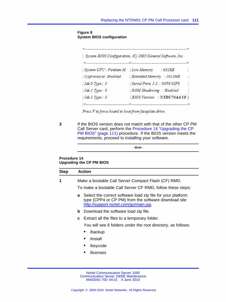
Replacing the NTDW61 CP PM Call Processor card 111
Figure 8System BIOS configuration
3 If the BIOS version does not match with that of the other CP PMCall Server card, perform the Procedure 14 “Upgrading the CPPM BIOS” (page 111) procedure. If the BIOS version meets therequirements, proceed to installing your software.
--End--
Procedure 14Upgrading the CP PM BIOS
Step Action
1 Make a bootable Call Server Compact Flash (CF) RMD.
To make a bootable Call Server CF RMD, follow these steps:
a Select the correct software load zip file for your platformtype (CPP4 or CP PM) from the software download sitehttp://support.nortel.com/go/main.jsp.
b Download the software load zip file.
c Extract all the files to a temporary folder.
You will see 6 folders under the root directory, as follows:
• /backup
• /install
• /keycode
• /licenses
Nortel Communication Server 1000Communication Server 1000E Maintenance
NN43041-700 04.01 4 June 2010
Copyright © 2004-2010 Nortel Networks. All Rights Reserved.
.
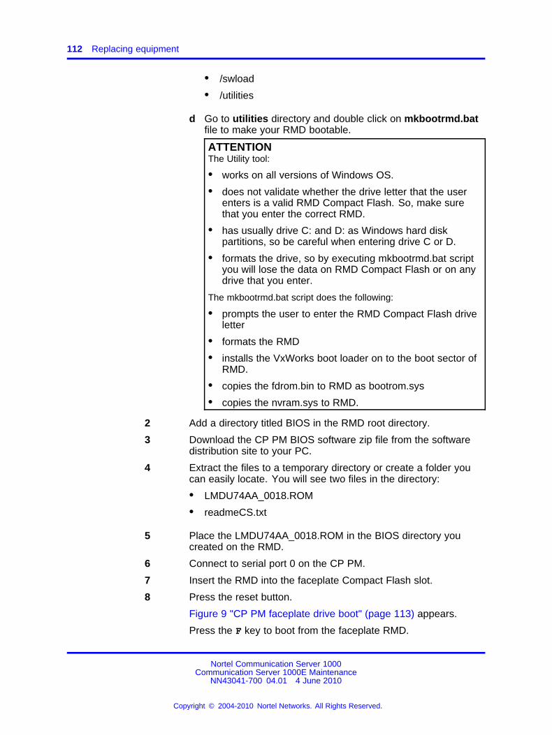
112 Replacing equipment
• /swload
• /utilities
d Go to utilities directory and double click on mkbootrmd.batfile to make your RMD bootable.
ATTENTIONThe Utility tool:
• works on all versions of Windows OS.
• does not validate whether the drive letter that the userenters is a valid RMD Compact Flash. So, make surethat you enter the correct RMD.
• has usually drive C: and D: as Windows hard diskpartitions, so be careful when entering drive C or D.
• formats the drive, so by executing mkbootrmd.bat scriptyou will lose the data on RMD Compact Flash or on anydrive that you enter.
The mkbootrmd.bat script does the following:
• prompts the user to enter the RMD Compact Flash driveletter
• formats the RMD
• installs the VxWorks boot loader on to the boot sector ofRMD.
• copies the fdrom.bin to RMD as bootrom.sys
• copies the nvram.sys to RMD.
2 Add a directory titled BIOS in the RMD root directory.
3 Download the CP PM BIOS software zip file from the softwaredistribution site to your PC.
4 Extract the files to a temporary directory or create a folder youcan easily locate. You will see two files in the directory:
• LMDU74AA_0018.ROM
• readmeCS.txt
5 Place the LMDU74AA_0018.ROM in the BIOS directory youcreated on the RMD.
6 Connect to serial port 0 on the CP PM.
7 Insert the RMD into the faceplate Compact Flash slot.
8 Press the reset button.
Figure 9 "CP PM faceplate drive boot" (page 113) appears.
Press the F key to boot from the faceplate RMD.
Nortel Communication Server 1000Communication Server 1000E Maintenance
NN43041-700 04.01 4 June 2010
Copyright © 2004-2010 Nortel Networks. All Rights Reserved.
.
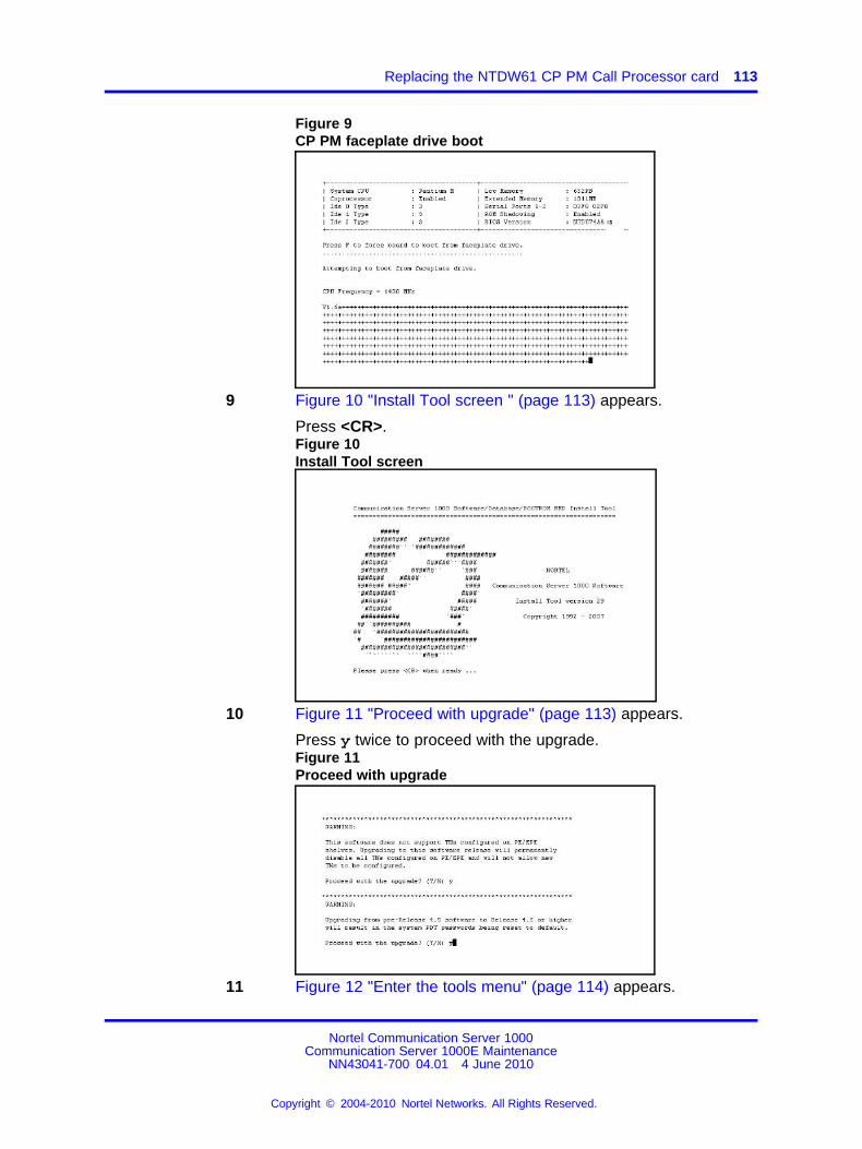
Replacing the NTDW61 CP PM Call Processor card 113
Figure 9CP PM faceplate drive boot
9 Figure 10 "Install Tool screen " (page 113) appears.
Press <CR>.Figure 10Install Tool screen
10 Figure 11 "Proceed with upgrade" (page 113) appears.
Press y twice to proceed with the upgrade.Figure 11Proceed with upgrade
11 Figure 12 "Enter the tools menu" (page 114) appears.
Nortel Communication Server 1000Communication Server 1000E Maintenance
NN43041-700 04.01 4 June 2010
Copyright © 2004-2010 Nortel Networks. All Rights Reserved.
.
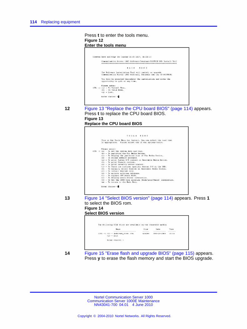
114 Replacing equipment
Press t to enter the tools menu.Figure 12Enter the tools menu
12 Figure 13 "Replace the CPU board BIOS" (page 114) appears.Press t to replace the CPU board BIOS.Figure 13Replace the CPU board BIOS
13 Figure 14 "Select BIOS version" (page 114) appears. Press 1to select the BIOS rom.Figure 14Select BIOS version
14 Figure 15 "Erase flash and upgrade BIOS" (page 115) appears.Press y to erase the flash memory and start the BIOS upgrade.
Nortel Communication Server 1000Communication Server 1000E Maintenance
NN43041-700 04.01 4 June 2010
Copyright © 2004-2010 Nortel Networks. All Rights Reserved.
.
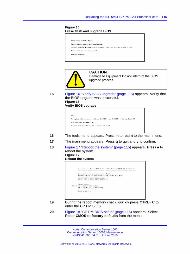
Replacing the NTDW61 CP PM Call Processor card 115
Figure 15Erase flash and upgrade BIOS
CAUTIONDamage to Equipment Do not interrupt the BIOSupgrade process.
15 Figure 16 "Verify BIOS upgrade" (page 115) appears. Verify thatthe BIOS upgrade was successful.Figure 16Verify BIOS upgrade
16 The tools menu appears. Press m to return to the main menu.
17 The main menu appears. Press q to quit and y to confirm.
18 Figure 17 "Reboot the system" (page 115) appears. Press a toreboot the system.Figure 17Reboot the system
19 During the reboot memory check, quickly press CTRL+ C toenter the CP PM BIOS.
20 Figure 18 "CP PM BIOS setup" (page 116) appears. SelectReset CMOS to factory defaults from the menu.
Nortel Communication Server 1000Communication Server 1000E Maintenance
NN43041-700 04.01 4 June 2010
Copyright © 2004-2010 Nortel Networks. All Rights Reserved.
.

116 Replacing equipment
Figure 18CP PM BIOS setup
21 Figure 19 "CP PM BIOS reset" (page 116) appears. Press y toreset CMOS to factory defaults.Figure 19CP PM BIOS reset
22 The system reboots. Once the reboot is complete, the new BIOSversion is displayed. Verify that the BIOS version is correct. Youcan now proceed with the Linux software installation.
Nortel Communication Server 1000Communication Server 1000E Maintenance
NN43041-700 04.01 4 June 2010
Copyright © 2004-2010 Nortel Networks. All Rights Reserved.
.
Replacing the NTDW61 CP PM Call Processor card 117
ATTENTIONIf you have reset the BIOS to factory defaults on an HA system,ensure that you re-define the ’CP PM Core Location |Side|Loop|Shelf|Information’. See Figure 13 "Replace the CPU board BIOS" (page114).
--End--
Running a High Availability system
Step Action
1 Check the card LED to verify that the Call Server card to bereplaced is inactive.
2 If the card is active, switch Call Servers in LD 135:
a In LD 135, load the program
b Enter the SCPU command to switch call servers (ifnecessary)
3 In LD 135, split the CPU cores using the SPLIT command.
--End--
Procedure 15Replacing the NTDW61 CP PM Call Processor card
Step Action
1 If running a High Availability system
2 Perform an EDD on the active core to back up the customerconfiguration database.
3 Label and remove all cables.
4 Unlock faceplate latches and remove card.
5 Remove the security dongle and insert it on the replacementcard.
6 Slide the CP PM Call processor into Slot 1 (or higher) of thechassis.
Slot 1 provides for easiest cabling.
7 Lock in the card using the faceplate latches.
8 Reconnect all cables.
9 To install the software on the CP PM Call Processor:
Nortel Communication Server 1000Communication Server 1000E Maintenance
NN43041-700 04.01 4 June 2010
Copyright © 2004-2010 Nortel Networks. All Rights Reserved.
.
118 Replacing equipment
1. Connect the terminal to port 0 with the NTAK19EC cable.
2. Insert the CF card into the Call Server faceplate.
3. Reboot the card by pressing the RST button on the faceplateof the Call Server. When prompted enter F to “force board toboot from faceplate drive” (prompt may appear twice).Figure 20Upgrade boot sequence
The Installation Tool banner screen appears:Figure 21Installation Tool banner
4. Enter y for both software warnings to proceed with theupgrade.
Note: PE/EPE is not applicable for this upgrade as it onlyapplies to large systems.
Nortel Communication Server 1000Communication Server 1000E Maintenance
NN43041-700 04.01 4 June 2010
Copyright © 2004-2010 Nortel Networks. All Rights Reserved.
.
Replacing the NTDW61 CP PM Call Processor card 119
5. The Software Installation Tool Main Menu appears (seeFigure 22 "Software Installation Tool Main Menu" (page119)).
Note: If the keycode files reside on a separate CF card,remove the software CF card and insert the CF cardcontaining the keycode files. The keycode normallyresides in the keycode folder of the OS CF card.
Figure 22Software Installation Tool Main Menu
6. Enter <CR> or u to access the Install menu. The followingscreen appears (see Figure 23 "Keycode files" (page 119)).Figure 23Keycode files
7. The keycode file appears in the list. Select the appropriatekeycode file for this system and install the keycode.
Note: If the CF card was exchanged, insert the CF cardcontaining CS 1000 Release 7.0.
8. Enter CR or y to confirm that the keycode matches thesystem software on the RMD (see Figure 24 "Keycodeconfirmation" (page 120)).
Nortel Communication Server 1000Communication Server 1000E Maintenance
NN43041-700 04.01 4 June 2010
Copyright © 2004-2010 Nortel Networks. All Rights Reserved.
.
120 Replacing equipment
Figure 24Keycode confirmation
9. The Install Menu appears he Install Menu appears (seeFigure 25 "Install Menu" (page 120)). Enter b to install thesoftware, database, and CP-BOOTROM.Figure 25Install Menu
The following screen appears (see Figure 26 "Sideinformation" (page 120)):
10. Enter <CR> or y to confirm that the call processor is set toside 0.Figure 26Side information
Nortel Communication Server 1000Communication Server 1000E Maintenance
NN43041-700 04.01 4 June 2010
Copyright © 2004-2010 Nortel Networks. All Rights Reserved.
.
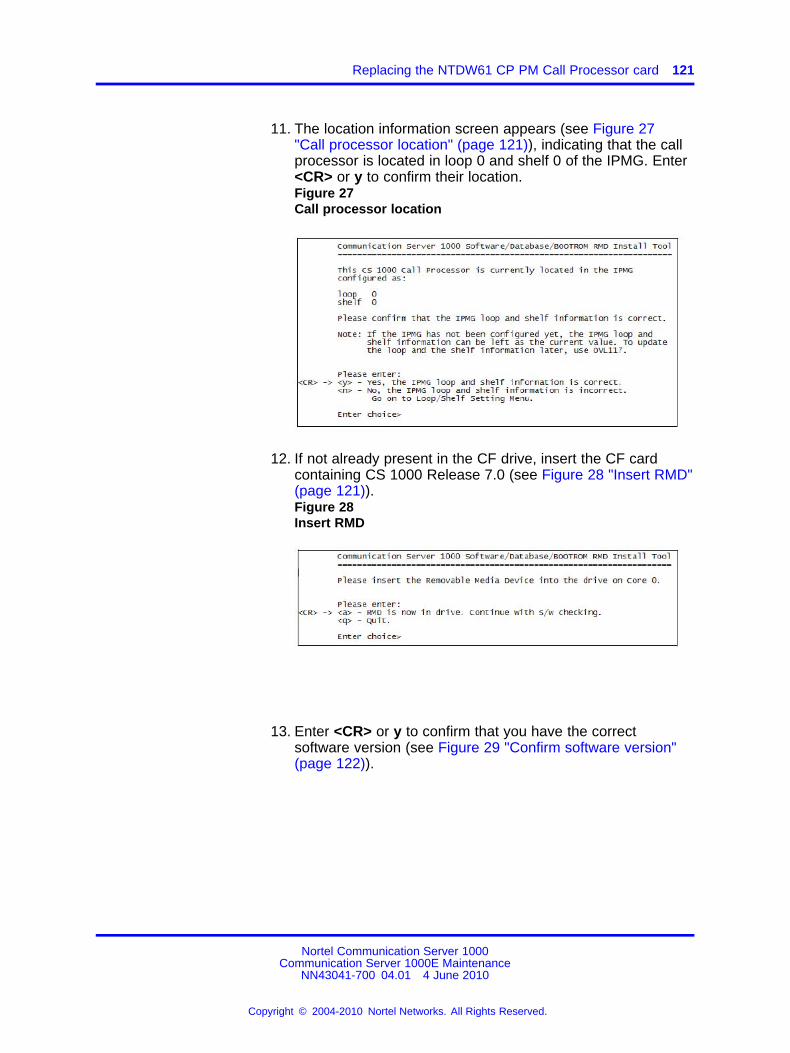
Replacing the NTDW61 CP PM Call Processor card 121
11. The location information screen appears (see Figure 27"Call processor location" (page 121)), indicating that the callprocessor is located in loop 0 and shelf 0 of the IPMG. Enter<CR> or y to confirm their location.Figure 27Call processor location
12. If not already present in the CF drive, insert the CF cardcontaining CS 1000 Release 7.0 (see Figure 28 "Insert RMD"(page 121)).Figure 28Insert RMD
13. Enter <CR> or y to confirm that you have the correctsoftware version (see Figure 29 "Confirm software version"(page 122)).
Nortel Communication Server 1000Communication Server 1000E Maintenance
NN43041-700 04.01 4 June 2010
Copyright © 2004-2010 Nortel Networks. All Rights Reserved.
.
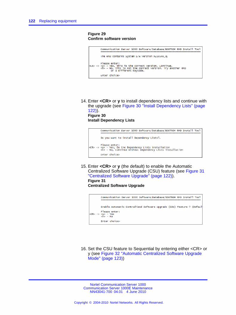
122 Replacing equipment
Figure 29Confirm software version
14. Enter <CR> or y to install dependency lists and continue withthe upgrade (see Figure 30 "Install Dependency Lists" (page122)).Figure 30Install Dependency Lists
15. Enter <CR> or y (the default) to enable the AutomaticCentralized Software Upgrade (CSU) feature (see Figure 31"Centralized Software Upgrade" (page 122)).Figure 31Centralized Software Upgrade
16. Set the CSU feature to Sequential by entering either <CR> ory (see Figure 32 "Automatic Centralized Software UpgradeMode" (page 123))
Nortel Communication Server 1000Communication Server 1000E Maintenance
NN43041-700 04.01 4 June 2010
Copyright © 2004-2010 Nortel Networks. All Rights Reserved.
.
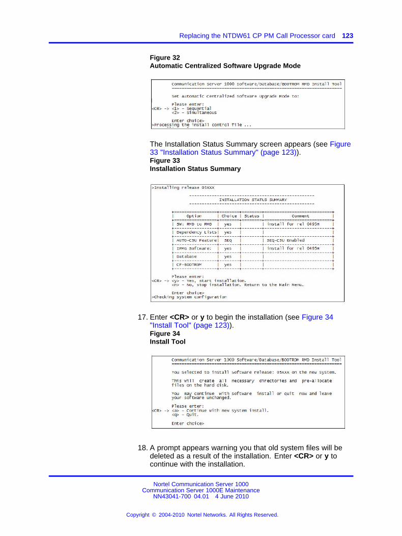
Replacing the NTDW61 CP PM Call Processor card 123
Figure 32Automatic Centralized Software Upgrade Mode
The Installation Status Summary screen appears (see Figure33 "Installation Status Summary" (page 123)).Figure 33Installation Status Summary
17. Enter <CR> or y to begin the installation (see Figure 34"Install Tool" (page 123)).Figure 34Install Tool
18. A prompt appears warning you that old system files will bedeleted as a result of the installation. Enter <CR> or y tocontinue with the installation.
Nortel Communication Server 1000Communication Server 1000E Maintenance
NN43041-700 04.01 4 June 2010
Copyright © 2004-2010 Nortel Networks. All Rights Reserved.
.
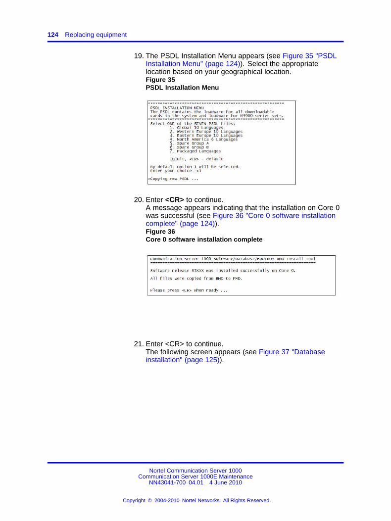
124 Replacing equipment
19. The PSDL Installation Menu appears (see Figure 35 "PSDLInstallation Menu" (page 124)). Select the appropriatelocation based on your geographical location.Figure 35PSDL Installation Menu
20. Enter <CR> to continue.A message appears indicating that the installation on Core 0was successful (see Figure 36 "Core 0 software installationcomplete" (page 124)).Figure 36Core 0 software installation complete
21. Enter <CR> to continue.The following screen appears (see Figure 37 "Databaseinstallation" (page 125)).
Nortel Communication Server 1000Communication Server 1000E Maintenance
NN43041-700 04.01 4 June 2010
Copyright © 2004-2010 Nortel Networks. All Rights Reserved.
.
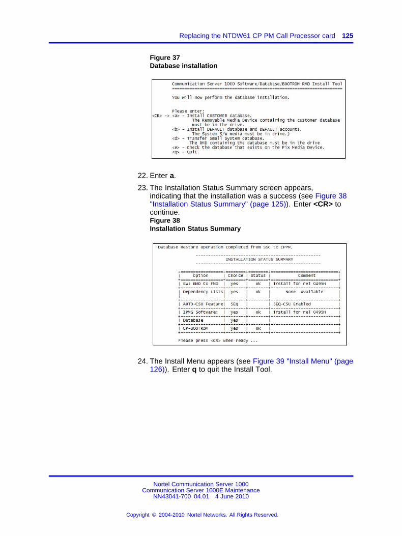
Replacing the NTDW61 CP PM Call Processor card 125
Figure 37Database installation
22. Enter a.
23. The Installation Status Summary screen appears,indicating that the installation was a success (see Figure 38"Installation Status Summary" (page 125)). Enter <CR> tocontinue.Figure 38Installation Status Summary
24. The Install Menu appears (see Figure 39 "Install Menu" (page126)). Enter q to quit the Install Tool.
Nortel Communication Server 1000Communication Server 1000E Maintenance
NN43041-700 04.01 4 June 2010
Copyright © 2004-2010 Nortel Networks. All Rights Reserved.
.
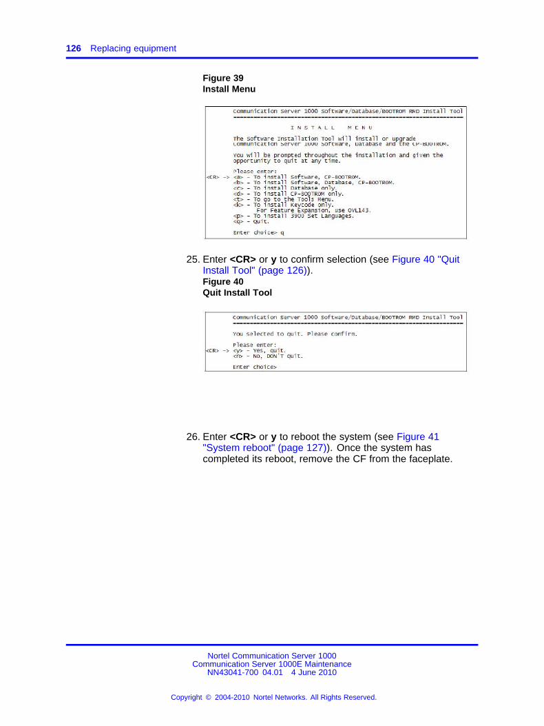
126 Replacing equipment
Figure 39Install Menu
25. Enter <CR> or y to confirm selection (see Figure 40 "QuitInstall Tool" (page 126)).Figure 40Quit Install Tool
26. Enter <CR> or y to reboot the system (see Figure 41"System reboot" (page 127)). Once the system hascompleted its reboot, remove the CF from the faceplate.
Nortel Communication Server 1000Communication Server 1000E Maintenance
NN43041-700 04.01 4 June 2010
Copyright © 2004-2010 Nortel Networks. All Rights Reserved.
.
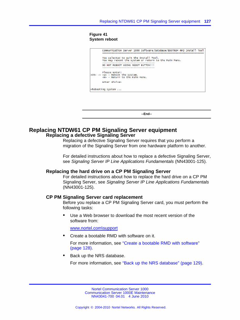
Replacing NTDW61 CP PM Signaling Server equipment 127
Figure 41System reboot
--End--
Replacing NTDW61 CP PM Signaling Server equipmentReplacing a defective Signaling Server
Replacing a defective Signaling Server requires that you perform amigration of the Signaling Server from one hardware platform to another.
For detailed instructions about how to replace a defective Signaling Server,see Signaling Server IP Line Applications Fundamentals (NN43001-125).
Replacing the hard drive on a CP PM Signaling ServerFor detailed instructions about how to replace the hard drive on a CP PMSignaling Server, see Signaling Server IP Line Applications Fundamentals(NN43001-125).
CP PM Signaling Server card replacementBefore you replace a CP PM Signaling Server card, you must perform thefollowing tasks:
• Use a Web browser to download the most recent version of thesoftware from:
www.nortel.com\support
• Create a bootable RMD with software on it.
For more information, see “Create a bootable RMD with software”(page 128).
• Back up the NRS database.
For more information, see “Back up the NRS database” (page 129).
Nortel Communication Server 1000Communication Server 1000E Maintenance
NN43041-700 04.01 4 June 2010
Copyright © 2004-2010 Nortel Networks. All Rights Reserved.
.
128 Replacing equipment
Create a bootable RMD with software
CAUTIONData LossThe PC utility used in the following procedure (mkbootrmd.exe)does not validate whether the drive letter entered is a valid RMDCF card. You must enter the correct RMD drive letter whenprompted or risk formatting the incorrect drive.
The installation RMD CF card must come preformatted and bootablefrom Nortel . Consumer CF cards are not bootable by default and mustbe made bootable. For more information, see Procedure 16 “Creating abootable RMD with software” (page 128).
Procedure 16Creating a bootable RMD with software
Step Action
1 After downloading the software image file, unzip it to a directoryon your PC.
2 Open the mkboot folder.
3 Double click the mkbootrmd.bat file.
The mkbootrmd.exe utility is supported by all versions ofMicrosoft Windows.
4 After you see the prompt to do so, insert a blank 512 MByte CFcard and press any key to continue.
5 At the prompt, enter the correct drive letter of the RMD and pressEnter.
The following prompt appears:
Insert new disk for drive (drive letter:) and press ENTER whenready...
6 Press Enter.
The disk is formatted and the boot sector files are created.
After the boot sector files (bootrom.sys and nvram.sys) aresuccessfully copied, the CF card is bootable
A message appears stating the following:
Check whether the following output shows "All the specifiedfile(s) are contiguous"
* * * Warning * * *IF THE FILES ARE NOT CONTIGUOUS, PLEASE RECREATETHE RMD* * * * * * * * * *Press any key to continue . . .
Nortel Communication Server 1000Communication Server 1000E Maintenance
NN43041-700 04.01 4 June 2010
Copyright © 2004-2010 Nortel Networks. All Rights Reserved.
.
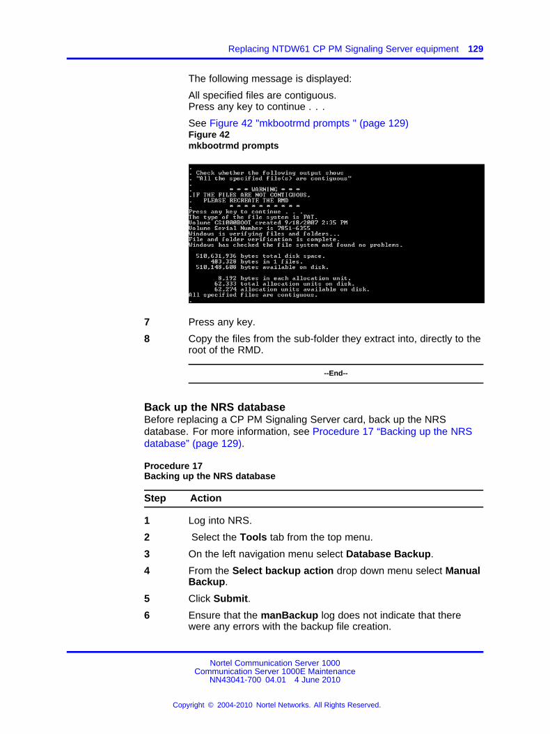
Replacing NTDW61 CP PM Signaling Server equipment 129
The following message is displayed:
All specified files are contiguous.Press any key to continue . . .
See Figure 42 "mkbootrmd prompts " (page 129)Figure 42mkbootrmd prompts
7 Press any key.
8 Copy the files from the sub-folder they extract into, directly to theroot of the RMD.
--End--
Back up the NRS databaseBefore replacing a CP PM Signaling Server card, back up the NRSdatabase. For more information, see Procedure 17 “Backing up the NRSdatabase” (page 129).
Procedure 17Backing up the NRS database
Step Action
1 Log into NRS.
2 Select the Tools tab from the top menu.
3 On the left navigation menu select Database Backup.
4 From the Select backup action drop down menu select ManualBackup.
5 Click Submit.
6 Ensure that the manBackup log does not indicate that therewere any errors with the backup file creation.
Nortel Communication Server 1000Communication Server 1000E Maintenance
NN43041-700 04.01 4 June 2010
Copyright © 2004-2010 Nortel Networks. All Rights Reserved.
.
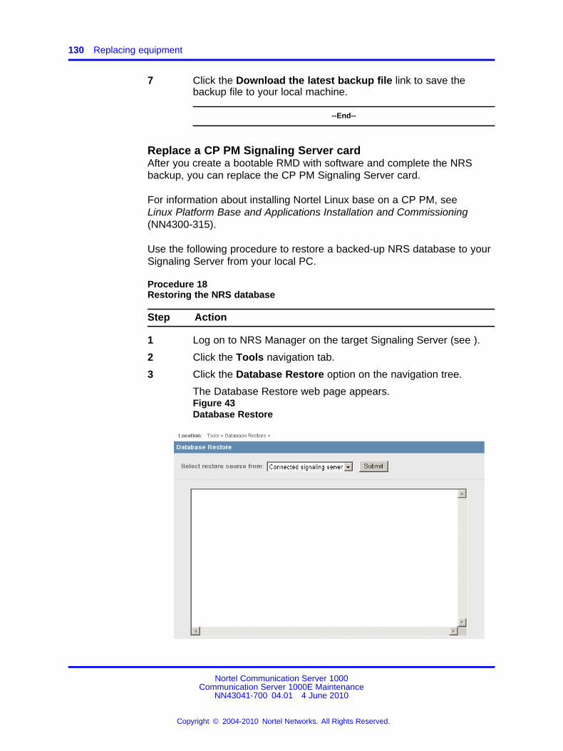
130 Replacing equipment
7 Click the Download the latest backup file link to save thebackup file to your local machine.
--End--
Replace a CP PM Signaling Server cardAfter you create a bootable RMD with software and complete the NRSbackup, you can replace the CP PM Signaling Server card.
For information about installing Nortel Linux base on a CP PM, seeLinux Platform Base and Applications Installation and Commissioning(NN4300-315).
Use the following procedure to restore a backed-up NRS database to yourSignaling Server from your local PC.
Procedure 18Restoring the NRS database
Step Action
1 Log on to NRS Manager on the target Signaling Server (see ).
2 Click the Tools navigation tab.
3 Click the Database Restore option on the navigation tree.
The Database Restore web page appears.Figure 43Database Restore
Nortel Communication Server 1000Communication Server 1000E Maintenance
NN43041-700 04.01 4 June 2010
Copyright © 2004-2010 Nortel Networks. All Rights Reserved.
.
Replacing the NTDW60 Media Gateway Controller card 131
4 Select the Connected Signaling Server option from the Selectrestore source from drop-down list and click Submit to restorethe NRS database.
Data from the old StandBy database is replaced with data fromthe new NRS database.
Monitor the log messages that appear in the browser window.If additional log analysis is necessary, a generated XML file isaccessible to the user.
Monitor these key logs:
• Logs indicating that some entries cannot be restoredcorrectly:
— The particular entry does not exist in the new database,so the user must check and provision it manually.
• Messages indicating corruption of the nrsback.tar file:
— The nrsback.tar file is not properly formatted or thecontent is not recognizable to the Restoring tool. Theuser must check the tar file and possibly regenerate andupload it again.
ATTENTIONThe new NRS database is loaded in standby DB view. You mustactivate the new NRS database to complete the migration process.
--End--
Replacing the NTDW60 Media Gateway Controller cardATTENTIONPrior to starting this procedure, ensure that all of the latest MGC Loadwarepatches are applied to the PBX.
Procedure 19Replacing the NTDW60 Media Gateway Controller card
Step Action
1 Log into Element Manager.
2 Go to System/IP Network and click Media Gateways.
3 Select the Media Gateway Controller card (MGC card) that is tobe replaced.Record the MGC card ELAN and TLAN IP information and theELAN IP and hostname of the PBX.
4 Power down the chassis where the card is being replaced.
Nortel Communication Server 1000Communication Server 1000E Maintenance
NN43041-700 04.01 4 June 2010
Copyright © 2004-2010 Nortel Networks. All Rights Reserved.
.
132 Replacing equipment
5 Label and remove all cables.
6 Unlock the faceplate latches.
7 Remove the NTDW60 MGC card from the Media Gateway andplace the card on a clean, electrostatic discharge (ESD) surface.
8 Place the new NTDW60 MGC card on a clean, electrostaticdischarge surface.
9 Remove the daughterboards from the defective MGC card. Becertain to note the card position (position 1 or position 2) thecards are removed from.
10 Reinstall the DSP daughterboards in the same position (position1 or position 2) on the replacement MGC card. For moreinformation, see“Replacing the NTDW62 or NTDW64 DSPdaughterboard” (page 133).
11 Insert the MGC card into Slot 0 of the chassis.
12 Reconnect all cables.
13 Connect a terminal (9600-N-8-1) to port 0 of the Serial cableconnected to the MGC card and boot the card.
14 Enter the following information from the old card for each of thefollowing fields:
Hostname: (optional)ELAN IP: 0.0.0.0ELAN subnet mask: 0.0.0.0ELAN gateway IP:TLAN IP: 0.0.0.0TLAN subnet mask: 0.0.0.0TLAN gateway IP :Primary CS Hostname: (optional)Primary CS IP:Leading Secondary CS Hostname:<enter>Leading Secondary CS IP: 0.0.0.0Secondary CS Hostname:<enter>Secondary CS IP: 0.0.0.0
15 Reboot the MGC card.
16 Go to Element Manager and navigate to IP Telephony/MediaGateway.
17 Select the gateway you just replaced.
18 Verify the first screen information is correct and click Next.
Nortel Communication Server 1000Communication Server 1000E Maintenance
NN43041-700 04.01 4 June 2010
Copyright © 2004-2010 Nortel Networks. All Rights Reserved.
.
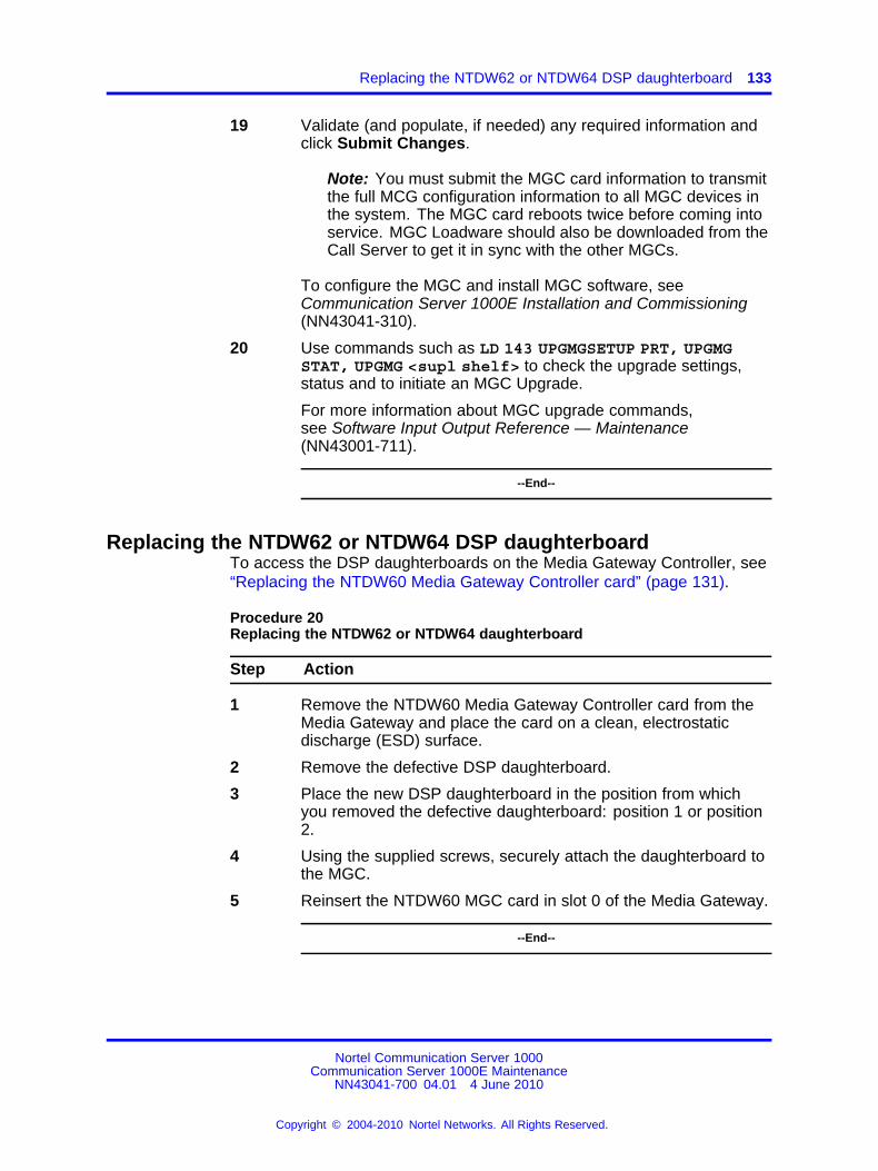
Replacing the NTDW62 or NTDW64 DSP daughterboard 133
19 Validate (and populate, if needed) any required information andclick Submit Changes.
Note: You must submit the MGC card information to transmitthe full MCG configuration information to all MGC devices inthe system. The MGC card reboots twice before coming intoservice. MGC Loadware should also be downloaded from theCall Server to get it in sync with the other MGCs.
To configure the MGC and install MGC software, seeCommunication Server 1000E Installation and Commissioning(NN43041-310).
20 Use commands such as LD 143 UPGMGSETUP PRT, UPGMGSTAT, UPGMG <supl shelf> to check the upgrade settings,status and to initiate an MGC Upgrade.
For more information about MGC upgrade commands,see Software Input Output Reference — Maintenance(NN43001-711).
--End--
Replacing the NTDW62 or NTDW64 DSP daughterboardTo access the DSP daughterboards on the Media Gateway Controller, see“Replacing the NTDW60 Media Gateway Controller card” (page 131).
Procedure 20Replacing the NTDW62 or NTDW64 daughterboard
Step Action
1 Remove the NTDW60 Media Gateway Controller card from theMedia Gateway and place the card on a clean, electrostaticdischarge (ESD) surface.
2 Remove the defective DSP daughterboard.
3 Place the new DSP daughterboard in the position from whichyou removed the defective daughterboard: position 1 or position2.
4 Using the supplied screws, securely attach the daughterboard tothe MGC.
5 Reinsert the NTDW60 MGC card in slot 0 of the Media Gateway.
--End--
Nortel Communication Server 1000Communication Server 1000E Maintenance
NN43041-700 04.01 4 June 2010
Copyright © 2004-2010 Nortel Networks. All Rights Reserved.
.
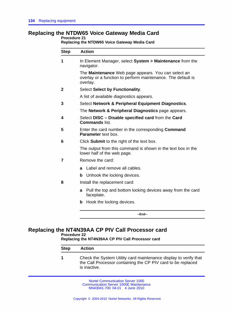
134 Replacing equipment
Replacing the NTDW65 Voice Gateway Media CardProcedure 21Replacing the NTDW65 Voice Gateway Media Card
Step Action
1 In Element Manager, select System > Maintenance from thenavigator.
The Maintenance Web page appears. You can select anoverlay or a function to perform maintenance. The default isoverlay.
2 Select Select by Functionality.
A list of available diagnostics appears.
3 Select Network & Peripheral Equipment Diagnostics.
The Network & Peripheral Diagnostics page appears.
4 Select DISC – Disable specified card from the CardCommands list.
5 Enter the card number in the corresponding CommandParameter text box.
6 Click Submit to the right of the text box.
The output from this command is shown in the text box in thelower half of the web page.
7 Remove the card:
a Label and remove all cables.
b Unhook the locking devices.
8 Install the replacement card:
a Pull the top and bottom locking devices away from the cardfaceplate.
b Hook the locking devices.
--End--
Replacing the NT4N39AA CP PIV Call Processor cardProcedure 22Replacing the NT4N39AA CP PIV Call Processor card
Step Action
1 Check the System Utility card maintenance display to verify thatthe Call Processor containing the CP PIV card to be replacedis inactive.
Nortel Communication Server 1000Communication Server 1000E Maintenance
NN43041-700 04.01 4 June 2010
Copyright © 2004-2010 Nortel Networks. All Rights Reserved.
.
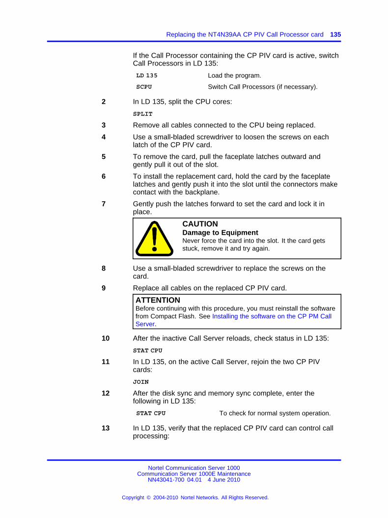
Replacing the NT4N39AA CP PIV Call Processor card 135
If the Call Processor containing the CP PIV card is active, switchCall Processors in LD 135:
LD 135 Load the program.
SCPU Switch Call Processors (if necessary).
2 In LD 135, split the CPU cores:
SPLIT
3 Remove all cables connected to the CPU being replaced.
4 Use a small-bladed screwdriver to loosen the screws on eachlatch of the CP PIV card.
5 To remove the card, pull the faceplate latches outward andgently pull it out of the slot.
6 To install the replacement card, hold the card by the faceplatelatches and gently push it into the slot until the connectors makecontact with the backplane.
7 Gently push the latches forward to set the card and lock it inplace.
CAUTIONDamage to EquipmentNever force the card into the slot. It the card getsstuck, remove it and try again.
8 Use a small-bladed screwdriver to replace the screws on thecard.
9 Replace all cables on the replaced CP PIV card.
ATTENTIONBefore continuing with this procedure, you must reinstall the softwarefrom Compact Flash. See Installing the software on the CP PM CallServer.
10 After the inactive Call Server reloads, check status in LD 135:
STAT CPU
11 In LD 135, on the active Call Server, rejoin the two CP PIVcards:
JOIN
12 After the disk sync and memory sync complete, enter thefollowing in LD 135:
STAT CPU To check for normal system operation.
13 In LD 135, verify that the replaced CP PIV card can control callprocessing:
Nortel Communication Server 1000Communication Server 1000E Maintenance
NN43041-700 04.01 4 June 2010
Copyright © 2004-2010 Nortel Networks. All Rights Reserved.
.
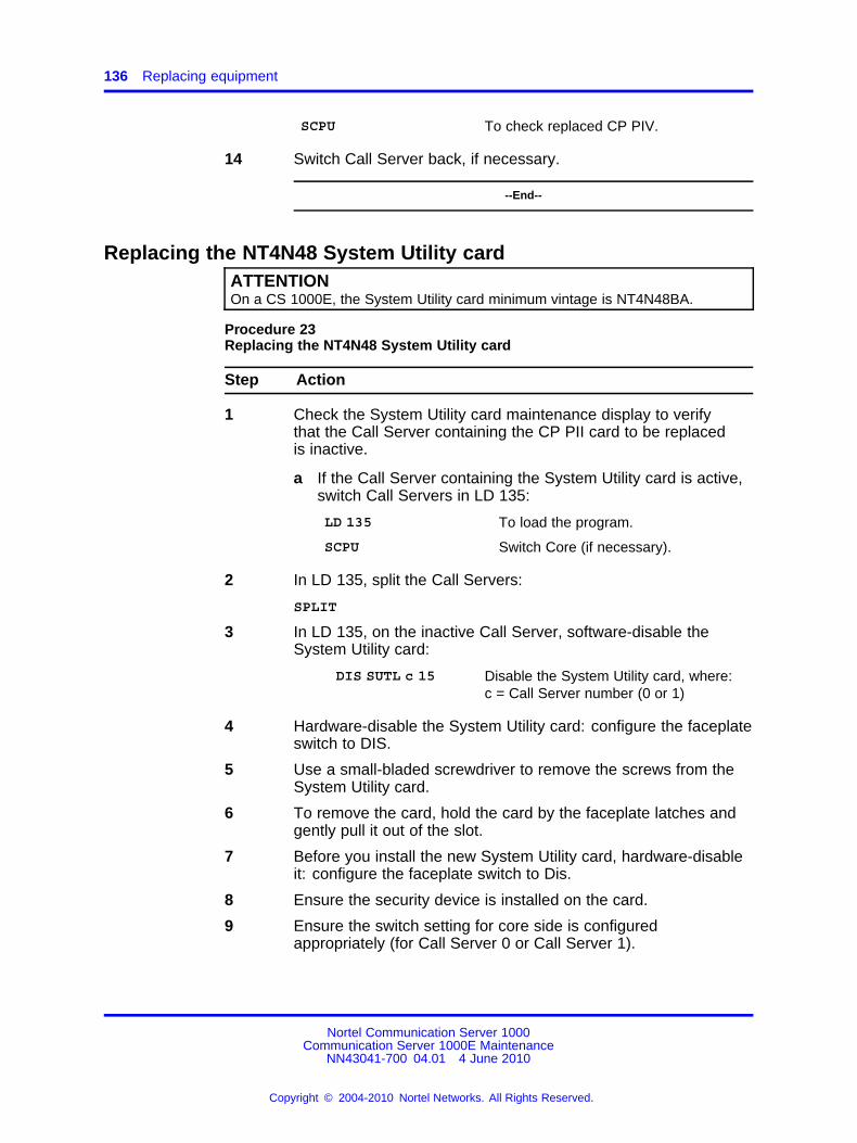
136 Replacing equipment
SCPU To check replaced CP PIV.
14 Switch Call Server back, if necessary.
--End--
Replacing the NT4N48 System Utility cardATTENTIONOn a CS 1000E, the System Utility card minimum vintage is NT4N48BA.
Procedure 23Replacing the NT4N48 System Utility card
Step Action
1 Check the System Utility card maintenance display to verifythat the Call Server containing the CP PII card to be replacedis inactive.
a If the Call Server containing the System Utility card is active,switch Call Servers in LD 135:
LD 135 To load the program.
SCPU Switch Core (if necessary).
2 In LD 135, split the Call Servers:
SPLIT
3 In LD 135, on the inactive Call Server, software-disable theSystem Utility card:
DIS SUTL c 15 Disable the System Utility card, where:c = Call Server number (0 or 1)
4 Hardware-disable the System Utility card: configure the faceplateswitch to DIS.
5 Use a small-bladed screwdriver to remove the screws from theSystem Utility card.
6 To remove the card, hold the card by the faceplate latches andgently pull it out of the slot.
7 Before you install the new System Utility card, hardware-disableit: configure the faceplate switch to Dis.
8 Ensure the security device is installed on the card.
9 Ensure the switch setting for core side is configuredappropriately (for Call Server 0 or Call Server 1).
Nortel Communication Server 1000Communication Server 1000E Maintenance
NN43041-700 04.01 4 June 2010
Copyright © 2004-2010 Nortel Networks. All Rights Reserved.
.
Replacing the NTDU67 Drive Carrier card (CP PII only) 137
10 To install the replacement card, hold the card by the faceplatelatches and gently push it into the slot until the connectors makecontact with the backplane.
11 Gently push the latches forward to set the card and lock it inplace.
CAUTIONDamage to EquipmentNever force the card into the slot. It the card getsstuck, remove it and try again.
12 Use a small-bladed screwdriver to tighten the screws on thecard.
13 Hardware-enable the System Utility card: configure the faceplateswitch to ENB.
14 In LD 135, software-enable the System Utility card:
ENL SUTL c 15 Enable the System Utility card, where:c = Call Server number (0 or 1)
15 In LD 135, check status:
STAT SUTL c 15 Check the System Utility card status,where:c = Call Server number (0 or 1)
16 In LD 135, on the active Call Server, rejoin the two Call Servers:
JOIN
--End--
Replacing the NTDU67 Drive Carrier card (CP PII only)See Software Input/Output Administration NN43001-611 for a descriptionof all maintenance commands, and Software Input/Output Reference –System Messages NN43001-712 for interpreting system messages.
CAUTIONService InterruptionAt some point in this procedure, the system warm starts,causing a momentary interruption in call processing.
Procedure 24Replacing the NTDU67 Drive Carrier card
Nortel Communication Server 1000Communication Server 1000E Maintenance
NN43041-700 04.01 4 June 2010
Copyright © 2004-2010 Nortel Networks. All Rights Reserved.
.
138 Replacing equipment
Step Action
1 Check the Drive Carrier card maintenance display to verify thatthe Call Server containing the Drive Carrier card to be replacedis inactive.
a If the Call Server containing the Drive Carrier card is active,switch cores in LD 135:
LD 135 To load the program.
SCPU Switch Core (if necessary).
2 In LD 135, split the CPU Cores:
SPLIT
3 Power down the Call Server using the power switch at the rightrear of the Call Server.
4 Use a small-bladed screwdriver to loosen the four screws on theDrive Carrier card.
5 Unhook the locking devices and remove the Drive Carrier card.
6 Put the Drive Carrier card being replaced into a static bag andbox.
7 Insert the new Drive Carrier card into the Call Server slot.
8 Lock the locking devices by pushing them gently towards thefaceplate.
9 Use a small-bladed screwdriver to tighten the screws on theDrive Carrier card.
10 Press the Reset button on the CP PII Call Processor card.
When the keycode is validated against the Security Device, theInstall menu is displayed.
11 Choose <b> - To Install Software, Database, CP-BOOTROMfrom the Install Menu.
12 Install the Operating Software from the Install Disk. SeeCommunication Server 1000E Software Upgrades
NN43041-458.
13 Install the Customer Database.
14 In LD 135, check status:
STAT CMDU This checks the Drive Carrier cardstatus
15 In LD 135, on the active Call Server, rejoin the two Call Servers:
Nortel Communication Server 1000Communication Server 1000E Maintenance
NN43041-700 04.01 4 June 2010
Copyright © 2004-2010 Nortel Networks. All Rights Reserved.
.
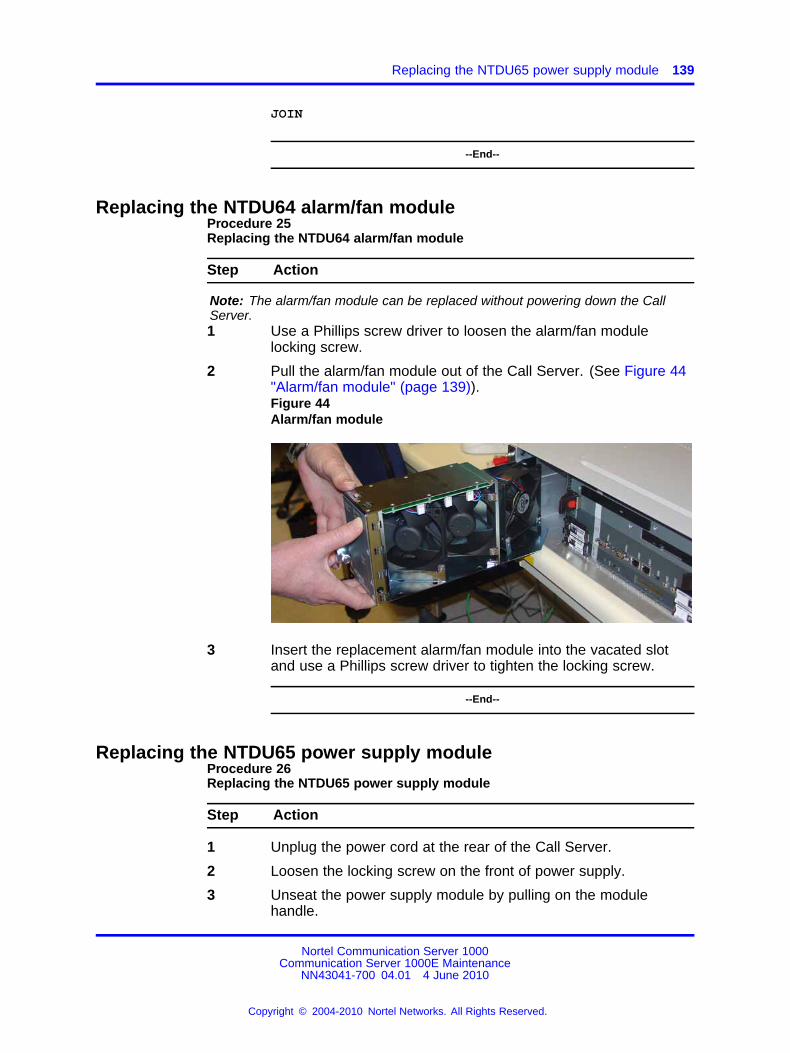
Replacing the NTDU65 power supply module 139
JOIN
--End--
Replacing the NTDU64 alarm/fan moduleProcedure 25Replacing the NTDU64 alarm/fan module
Step Action
Note: The alarm/fan module can be replaced without powering down the CallServer.1 Use a Phillips screw driver to loosen the alarm/fan module
locking screw.
2 Pull the alarm/fan module out of the Call Server. (See Figure 44"Alarm/fan module" (page 139)).Figure 44Alarm/fan module
3 Insert the replacement alarm/fan module into the vacated slotand use a Phillips screw driver to tighten the locking screw.
--End--
Replacing the NTDU65 power supply moduleProcedure 26Replacing the NTDU65 power supply module
Step Action
1 Unplug the power cord at the rear of the Call Server.
2 Loosen the locking screw on the front of power supply.
3 Unseat the power supply module by pulling on the modulehandle.
Nortel Communication Server 1000Communication Server 1000E Maintenance
NN43041-700 04.01 4 June 2010
Copyright © 2004-2010 Nortel Networks. All Rights Reserved.
.
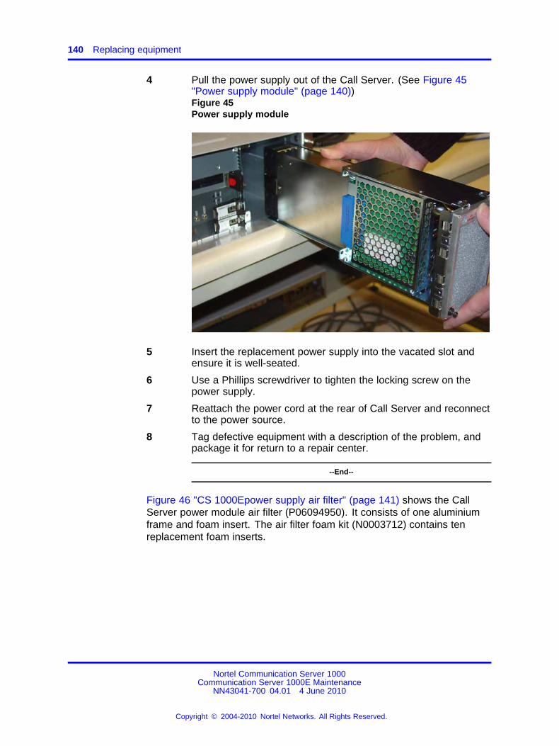
140 Replacing equipment
4 Pull the power supply out of the Call Server. (See Figure 45"Power supply module" (page 140))Figure 45Power supply module
5 Insert the replacement power supply into the vacated slot andensure it is well-seated.
6 Use a Phillips screwdriver to tighten the locking screw on thepower supply.
7 Reattach the power cord at the rear of Call Server and reconnectto the power source.
8 Tag defective equipment with a description of the problem, andpackage it for return to a repair center.
--End--
Figure 46 "CS 1000Epower supply air filter" (page 141) shows the CallServer power module air filter (P06094950). It consists of one aluminiumframe and foam insert. The air filter foam kit (N0003712) contains tenreplacement foam inserts.
Nortel Communication Server 1000Communication Server 1000E Maintenance
NN43041-700 04.01 4 June 2010
Copyright © 2004-2010 Nortel Networks. All Rights Reserved.
.
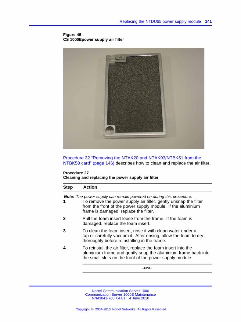
Replacing the NTDU65 power supply module 141
Figure 46CS 1000Epower supply air filter
Procedure 32 “Removing the NTAK20 and NTAK93/NTBK51 from theNTBK50 card” (page 146) describes how to clean and replace the air filter.
Procedure 27Cleaning and replacing the power supply air filter
Step Action
Note: The power supply can remain powered on during this procedure.1 To remove the power supply air filter, gently unsnap the filter
from the front of the power supply module. If the aluminiumframe is damaged, replace the filter.
2 Pull the foam insert loose from the frame. If the foam isdamaged, replace the foam insert.
3 To clean the foam insert, rinse it with clean water under atap or carefully vacuum it. After rinsing, allow the foam to drythoroughly before reinstalling in the frame.
4 To reinstall the air filter, replace the foam insert into thealuminium frame and gently snap the aluminium frame back intothe small slots on the front of the power supply module.
--End--
Nortel Communication Server 1000Communication Server 1000E Maintenance
NN43041-700 04.01 4 June 2010
Copyright © 2004-2010 Nortel Networks. All Rights Reserved.
.
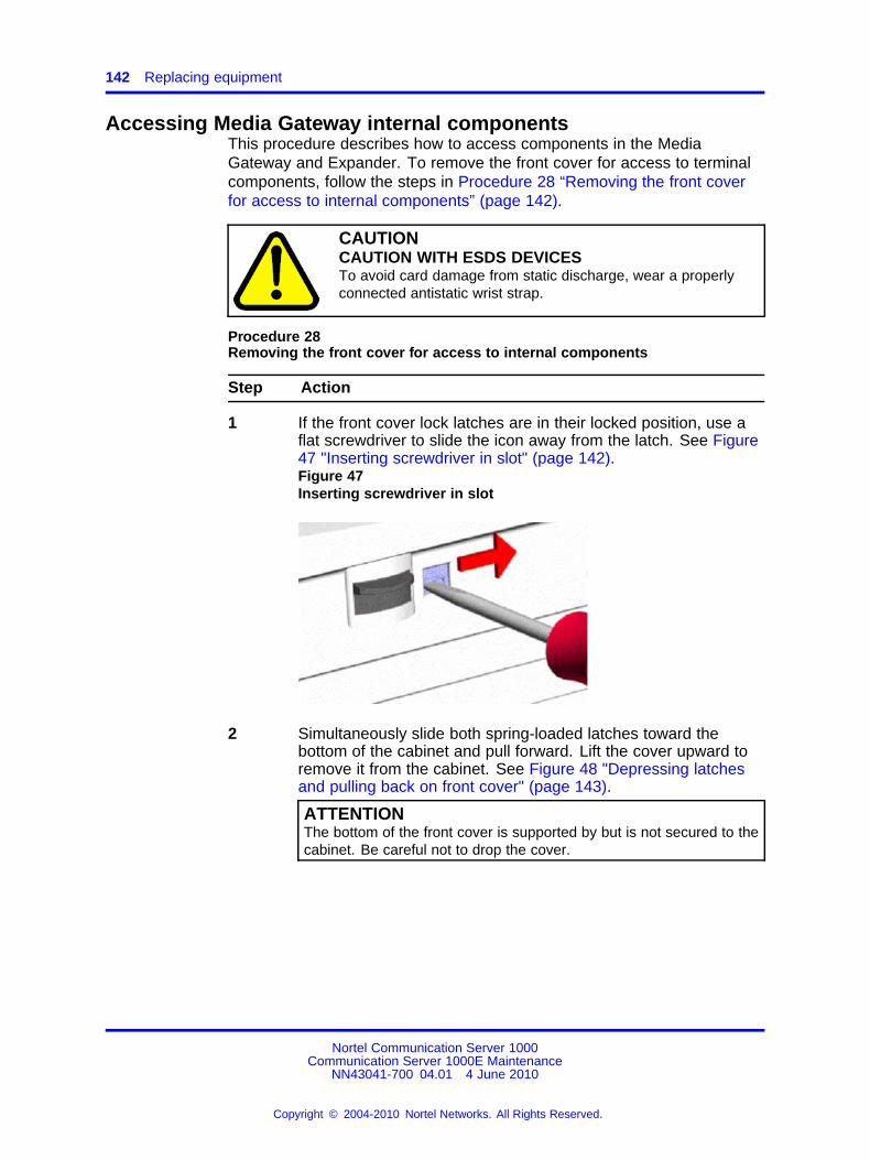
142 Replacing equipment
Accessing Media Gateway internal componentsThis procedure describes how to access components in the MediaGateway and Expander. To remove the front cover for access to terminalcomponents, follow the steps in Procedure 28 “Removing the front coverfor access to internal components” (page 142).
CAUTIONCAUTION WITH ESDS DEVICESTo avoid card damage from static discharge, wear a properlyconnected antistatic wrist strap.
Procedure 28Removing the front cover for access to internal components
Step Action
1 If the front cover lock latches are in their locked position, use aflat screwdriver to slide the icon away from the latch. See Figure47 "Inserting screwdriver in slot" (page 142).Figure 47Inserting screwdriver in slot
2 Simultaneously slide both spring-loaded latches toward thebottom of the cabinet and pull forward. Lift the cover upward toremove it from the cabinet. See Figure 48 "Depressing latchesand pulling back on front cover" (page 143).
ATTENTIONThe bottom of the front cover is supported by but is not secured to thecabinet. Be careful not to drop the cover.
Nortel Communication Server 1000Communication Server 1000E Maintenance
NN43041-700 04.01 4 June 2010
Copyright © 2004-2010 Nortel Networks. All Rights Reserved.
.
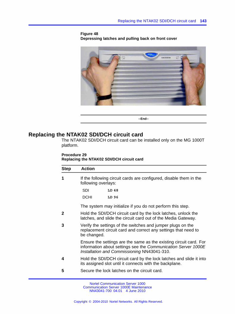
Replacing the NTAK02 SDI/DCH circuit card 143
Figure 48Depressing latches and pulling back on front cover
--End--
Replacing the NTAK02 SDI/DCH circuit cardThe NTAK02 SDI/DCH circuit card can be installed only on the MG 1000Tplatform.
Procedure 29Replacing the NTAK02 SDI/DCH circuit card
Step Action
1 If the following circuit cards are configured, disable them in thefollowing overlays:
SDI LD 48
DCHI LD 96
The system may initialize if you do not perform this step.
2 Hold the SDI/DCH circuit card by the lock latches, unlock thelatches, and slide the circuit card out of the Media Gateway.
3 Verify the settings of the switches and jumper plugs on thereplacement circuit card and correct any settings that need tobe changed.
Ensure the settings are the same as the existing circuit card. Forinformation about settings see the Communication Server 1000EInstallation and Commissioning NN43041-310.
4 Hold the SDI/DCH circuit card by the lock latches and slide it intoits assigned slot until it connects with the backplane.
5 Secure the lock latches on the circuit card.
Nortel Communication Server 1000Communication Server 1000E Maintenance
NN43041-700 04.01 4 June 2010
Copyright © 2004-2010 Nortel Networks. All Rights Reserved.
.
144 Replacing equipment
6 If the following circuit cards were previously disabled, enablethem in the following overlays:
SDI LD 48
DCHI LD 96
--End--
Replacing the NTAK03 TDS/DTR circuit cardProcedure 30Replacing the NTAK03 TDS/DTR circuit card
Step Action
1 Disable the SDI ports in LD 48.
2 Disable the TDS channels and Digitone Receivers in LD 34.
3 Hold the TDS/DTR circuit card by the lock latches, unlock thelatches, and slide the circuit card out of the Media Gateway.
4 Hold the replacement TDS/DTR circuit card by the lock latchesand slide it into its assigned slot until it connects with thebackplane.
5 Secure the lock latches on the circuit card.
6 Enable the SDI ports, TDS channels, and Digitone Receivers intheir respective overlays.
--End--
Replacing the NTAK79 or NTBK50 2.0 Mb PRI cardNTAK79 and NTBK50 2.0 Mb PRI cards can be installed only on the MG1000T platform.
Procedure 31Replacing the NTAK79 or NTBK50 2.0 Mb PRI card
Step Action
1 If the card is an NTAK79, or is an NTBK50 with the NTAK93DCHI daughterboard attached, disable the associated D-channelusing the following overlay and commands:
LD 96 DIS DCH X
If the card is an NTBK50 with the NTBK51 DDCH daughterboardattached, disable the associated downloadable D-channel usingthe following overlay and commands:
Nortel Communication Server 1000Communication Server 1000E Maintenance
NN43041-700 04.01 4 June 2010
Copyright © 2004-2010 Nortel Networks. All Rights Reserved.
.
Replacing the NTAK79 or NTBK50 2.0 Mb PRI card 145
LD 96 DIS DCH X
LD 96 DIS MSDL X
2 Disable the Clock Controller using these commands:
LD 60 DIS CC 0
3 Disable the PRI pack using these commands:
LD 60 DISL X
The LEDs on the front of the card change from green (enabled)to red (disabled.) For this to happen, the DIS MSDL commandmust be used, as in step 1.
4 Hold the circuit card by the lock latches, unlock the latches,and slide the circuit card out of the Media Gateway. If required,remove any daughterboards that may be attached. SeeProcedure 32 “Removing the NTAK20 and NTAK93/NTBK51from the NTBK50 card” (page 146).
5 On the replacement PRI circuit card, configure any switches andinstall any daughterboards as required. Hold the card by the locklatches and slide it into its assigned slot until it connects with thebackplane.
6 Secure the lock latches on the circuit card.
7 Enable the Clock Controller and the PRI in their correspondingoverlays:
LD 60 ENL CC 0
LD 60 ENLL X
The associated DCHI/DDCH is automatically enabled.
8 Check the tracking of the Clock Controller with the followingoverlay:
LD 60 SCK 0
If it is not tracking or is not locked, use the following commandsto track:
LD 60 TRCK PCK/SCLK
--End--
Removing daughterboards from the NTBK50 cardBecause of the physical layout of the motherboards and daughterboards,remove the NTAK20 before the NTAK93/NTBK51.
Nortel Communication Server 1000Communication Server 1000E Maintenance
NN43041-700 04.01 4 June 2010
Copyright © 2004-2010 Nortel Networks. All Rights Reserved.
.
146 Replacing equipment
Procedure 32Removing the NTAK20 and NTAK93/NTBK51 from the NTBK50 card
Step Action
1 Starting at the two corners opposite the connector, gently lifteach corner out of the locking groove of the standoff.
2 At the two corners adjacent to the connector, gently lift the entireside until the mounting holes are clear of the locking groove ofthe standoff.
3 To remove the connector pins, grasp the edge of the boardadjacent to the connector and lift gently.
--End--
If more than one NTBK50 card is installed, the additional cards may notcarry daughterboards, depending on the system configuration. At least oneNTAK20 for each system is required.
Mounting the daughterboardsWork on a flat, static-free surface when mounting or removingdaughterboards. To install the NTAK93 and NTBK51 daughterboardbefore the NTAK20 daughterboard, follow the steps in Procedure 33“Installing the NTAK93/NTBK51 daughterboard before the NTAK20daughterboard” (page 146).
Procedure 33Installing the NTAK93/NTBK51 daughterboard before the NTAK20daughterboard
Step Action
1 Visually inspect the connector pins on the underside of thedaughterboard. Realigned bent pins prior to mounting.
2 Place the NTBK50 flat on an antistatic pad.
3 From an overhead view, with the daughterboard parallel abovethe NTBK50 and the connector pins aligned over the connectorsockets, line up the mounting holes on the daughterboard withthe tops of the standoffs on the NTBK50.
4 Lower the daughterboard onto the NTBK50, keeping thestandoffs in line with all four holes, until the holes rest on thetops of the four standoffs.
5 If more than a very slight amount of pressure is required at thispoint, the connector pins may not be aligned with the connectorsocket. If so, lift the daughterboard off the NTBK50 and returnto Step 2.
Nortel Communication Server 1000Communication Server 1000E Maintenance
NN43041-700 04.01 4 June 2010
Copyright © 2004-2010 Nortel Networks. All Rights Reserved.
.
Replacing the NTAK09 1.5 Mb DTI/PRI card (PRI applications) 147
6 Apply pressure along the edge of the board where the connectoris located until the standoffs at the two corners adjacent to theconnector snap into a locked position.
7 Press down on the two corners opposite until they lock intoplace.
--End--
Replacing the NTAK09 1.5 Mb DTI/PRI card (PRI applications)Procedure 34Replacing the NTAK09 1.5 Mb DTI/PRI card when it is configured as PRI
Step Action
1 If the NTAK93 DCHI daughterboard is attached to the card,disable the associated D-channel using the following overlaycommands:
LD 96 DIS DCH X
If the NTBK51 DDCH daughterboard is attached to the card,disable the associated downloadable D-channel using thefollowing overlay commands:
LD 96 DIS DCH X
LD 96 DIS MSDL X
2 To disable the Clock Controller (if on PRI), use the followingcommand:
LD 60 DIS CC 0
3 To disable the PRI pack, use the following command:
LD 60 DIS L X
The LEDs on the front of the card change from green (enabled)to red (disabled.) For this to happen, the DIS MSDL commandmust be used, as in Step 1.
4 Hold the circuit card by the lock latches, unlock the latches,and slide the circuit card out of the Media Gateway. If required,remove any attached daughterboards . Because of the physicallayout of the motherboards and daughterboards, remove theNTAK20 before the NTAK93. To remove the NTAK20 andNTAK93 from the NTAK09 card, follow the steps in Procedure32 “Removing the NTAK20 and NTAK93/NTBK51 from theNTBK50 card” (page 146). To reinstall the daughterboards, seeProcedure 33 “Installing the NTAK93/NTBK51 daughterboardbefore the NTAK20 daughterboard” (page 146).
Nortel Communication Server 1000Communication Server 1000E Maintenance
NN43041-700 04.01 4 June 2010
Copyright © 2004-2010 Nortel Networks. All Rights Reserved.
.
148 Replacing equipment
5 On the replacement PRI circuit card, configure switches andinstall daughterboards as required. Hold the card by the locklatches and slide it into the assigned slot until it connects withthe backplane.
6 Secure the lock latches on the circuit card.
7 Enable the Clock Controller and the PRI in their correspondingoverlays:
LD 60 ENL CC 0
LD 60 ENLL X
The associated DCHI is automatically enabled.
8 Check the tracking of the Clock Controller with the followingcommand:
LD 60 SCK 0
If the clock is not tracking or is not locked, use the followingcommand to track:
LD 60 TRCK PCK/SCLK
--End--
Replacing the NTAK09, NTAK10, or NTRB21 circuit cards (DTIapplications)
To replace any card that is configured as a Digital Trunk Interface (DTI),use the following procedure.
Procedure 35Replacing the NTAK09, NTAK10, or NTRB21 when configured as a DTI
Step Action
1 Disable the Clock Controller by using the command:
LD 60 DIS CC 0
2 Disable the DTI pack by using the command:
LD 60 DISL X
3 Hold the circuit card by the lock latches, unlock the latches,and slide the circuit card out of the Media Gateway. If required,remove any daughterboards attached to the card.
4 On the replacement DTI circuit card, configure any switches andinstall any daughterboards as required. Hold the replacement
Nortel Communication Server 1000Communication Server 1000E Maintenance
NN43041-700 04.01 4 June 2010
Copyright © 2004-2010 Nortel Networks. All Rights Reserved.
.
Replacing equipment cards 149
DTI circuit card by the lock latches and slide it into the assignedslot until it connects with the backplane.
5 Enable the Clock Controller (if on the DTI) and the DTI in theircorresponding overlays:
LD 60 ENL CC 0
LD 60 ENLL X
6 Secure the lock latches on the circuit card.
7 Check the tracking of the Clock Controller with the followingoverlay:
LD 60 SSCK 0
If the clock is not tracking or is not locked, use the followingcommands to start tracking.
LD 60 TRCK PCK/SCLK
--End--
Replacing equipment cardsFollow the steps in Procedure 36 “Replacing equipment cards” (page149) to replace Intelligent Peripheral Equipment (IPE) cards, including thefollowing:
• NT8D02 Digital Line Card
• NT8D03 Analog Line Card
• NT8D09 Analog Message Waiting Line Card
• NT8D14 Universal Trunk Card
• NT8D15 E&M Trunk Card
See Software Input/Output Reference – Maintenance NN43001-711 andSoftware Input/Output Reference – System Messages NN43001-712 for adescription of all maintenance commands and system messages.
Procedure 36Replacing equipment cards
Step Action
1 Software-disable the card with the following command:
LD 32 DISC l s c
Nortel Communication Server 1000Communication Server 1000E Maintenance
NN43041-700 04.01 4 June 2010
Copyright © 2004-2010 Nortel Networks. All Rights Reserved.
.
150 Replacing equipment
2 Unhook the locking devices on the card. Pull it out of the cardcage.
3 On the replacement card, configure option switches or jumperplugs to the same settings as those on the card you removed.
4 Insert the replacement card into the vacated slot and hook thelocking devices.
When cards are installed, the red LED on the faceplate flashesas a self-test runs. If the self-test is completed successfully, thecard is automatically enabled (if it is configured in software) andthe LED goes out. If the self-test fails, the LED lights steadilyand remains lit.
5 Software-enable the card by entering: ENLC l s c
When the process is complete, a system response appears.
6 To end the program, enter four asterisks (****).
--End--
Replacing the NT5K21 equipment cardProcedure 37Replacing the NT5K21 XMFC/MFE equipment card
Step Action
1 Software-disable the card with the following command:
LD 54 DISC l s c
2 Unhook the locking devices on the card. Pull it out of the cardcage.
3 Insert the replacement card into the vacant slot and hook thelocking devices.
After you install cards, the red LED on the faceplate flashes as aself-test runs. If the self-test succeeds, the card is automaticallyenabled (if it is configured in software) and the LED turns off. Ifthe self-test fails, the LED lights steadily and remains lit.
4 Software-enable the card by entering: ENLC l s c
When the process is complete, a system response appears.
Nortel Communication Server 1000Communication Server 1000E Maintenance
NN43041-700 04.01 4 June 2010
Copyright © 2004-2010 Nortel Networks. All Rights Reserved.
.
Replacing the NTAK92 off-premises protection module 151
5 To end the program, enter four asterisks (****).
--End--
Replacing the NTAG26 equipment cardProcedure 38Replacing the NTAG26 equipment card
Step Action
1 Software-disable the card with the following command:
LD 34 DISC l s c
2 Unhook the locking devices on the card. Pull it out of the cardcage.
3 Insert the replacement card into the vacant slot and hook thelocking devices.
After you install cards, the red LED on the faceplate flashes as aself-test runs. If the self-test succeeds, the card is automaticallyenabled (if it is configured in software) and the LED turns off. Ifthe self-test fails, the LED lights steadily and remains lit.
4 Software-enable the card by entering: ENLC l s c
When the process is complete, a system response appears.
5 To end the program, enter four asterisks (****).
--End--
Replacing the NTAK92 off-premises protection moduleA lightening strike can cause failure of the NTAK92 protection assembly.The first indication of such a failure is an out-of-service telephone. Tocheck for and replace failed protectors, follow the steps in Procedure 39“Testing for loop closure” (page 151) or Procedure 40 “Testing continuity”(page 152).
Procedure 39Testing for loop closure
Step Action
1 To test for a dial tone across cable pairs on J1 and J2, usestandard loop closure test equipment (for example, butt-in). If
Nortel Communication Server 1000Communication Server 1000E Maintenance
NN43041-700 04.01 4 June 2010
Copyright © 2004-2010 Nortel Networks. All Rights Reserved.
.
152 Replacing equipment
a protector failed, go to Step 2. If not, go to the appropriatechapter in this guide.
2 Remove the protection module cover plate.
3 Remove the faulty protector.
4 Install a new protector in the same position as the faultyprotector.
5 Replace the cover plate.
6 Test the set for proper operation.
--End--
Procedure 40Testing continuity
Step Action
1 Remove the cover plate from the protection module.
2 Use an ohmmeter to measure continuity across the protectors.See Figure 49 "Wiring diagram for NTAK92 off-premisesprotection module" (page 153). If a protector failed, go to Step 3.If not, go to the appropriate chapter in this guide.
3 Remove the faulty protector.
4 Install a new protector in the same position as the faultyprotector.
5 Replace the cover plate.
6 Test the set for proper operation.
--End--
Nortel Communication Server 1000Communication Server 1000E Maintenance
NN43041-700 04.01 4 June 2010
Copyright © 2004-2010 Nortel Networks. All Rights Reserved.
.
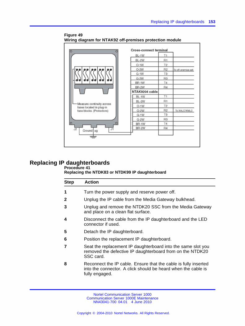
Replacing IP daughterboards 153
Figure 49Wiring diagram for NTAK92 off-premises protection module
Replacing IP daughterboardsProcedure 41Replacing the NTDK83 or NTDK99 IP daughterboard
Step Action
1 Turn the power supply and reserve power off.
2 Unplug the IP cable from the Media Gateway bulkhead.
3 Unplug and remove the NTDK20 SSC from the Media Gatewayand place on a clean flat surface.
4 Disconnect the cable from the IP daughterboard and the LEDconnector if used.
5 Detach the IP daughterboard.
6 Position the replacement IP daughterboard.
7 Seat the replacement IP daughterboard into the same slot youremoved the defective IP daughterboard from on the NTDK20SSC card.
8 Reconnect the IP cable. Ensure that the cable is fully insertedinto the connector. A click should be heard when the cable isfully engaged.
Nortel Communication Server 1000Communication Server 1000E Maintenance
NN43041-700 04.01 4 June 2010
Copyright © 2004-2010 Nortel Networks. All Rights Reserved.
.
154 Replacing equipment
9 Reconnect the LED connector that was disconnected in step 4 ifnecessary.
10 Record the MAC address of the new IP daughterboard installedon the SSC in the Media Gateway. When necessary use LD 117to configure the new MAC address for the Media Gateway. SeeCommunication Server 1000E Installation and Commissioning(NN43041-310).
11 Reinstall the NTDK20 SSC circuit card in slot 0 of the MediaGateway.
12 Reconnect the IP cable to the Media Gateway bulkhead.
13 Power up the system.
--End--
Nortel Communication Server 1000Communication Server 1000E Maintenance
NN43041-700 04.01 4 June 2010
Copyright © 2004-2010 Nortel Networks. All Rights Reserved.
.
155.
Element Manager
ContentsThis section contains the following topics:
• “Call Server maintenance” (page 155)
• “Call Server backup, data dump, and restore” (page 157)
• “Signaling Server maintenance” (page 158)
• “Media Card maintenance” (page 159)
• “LD 36 analog trunk card status” (page 160)
Call Server maintenanceTo perform maintenance on the Call Server, you can access a subset ofoverlay functions in Element Manager.
Search for maintenance functions by LD number or by functionality on thesystem maintenance page, as shown in Figure 50 "Element Manager CallServer maintenance" (page 156).
Nortel Communication Server 1000Communication Server 1000E Maintenance
NN43041-700 04.01 4 June 2010
Copyright © 2004-2010 Nortel Networks. All Rights Reserved.
.
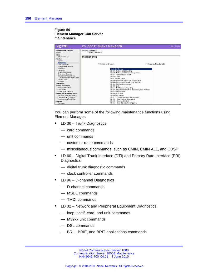
156 Element Manager
Figure 50Element Manager Call Servermaintenance
You can perform some of the following maintenance functions usingElement Manager.
• LD 36 – Trunk Diagnostics
— card commands
— unit commands
— customer route commands
— miscellaneous commands, such as CMIN, CMIN ALL, and CDSP
• LD 60 – Digital Trunk Interface (DTI) and Primary Rate Interface (PRI)Diagnostics
— digital trunk diagnostic commands
— clock controller commands
• LD 96 – D-channel Diagnostics
— D-channel commands
— MSDL commands
— TMDI commands
• LD 32 – Network and Peripheral Equipment Diagnostics
— loop, shelf, card, and unit commands
— M39xx unit commands
— DSL commands
— BRIL, BRIE, and BRIT applications commands
Nortel Communication Server 1000Communication Server 1000E Maintenance
NN43041-700 04.01 4 June 2010
Copyright © 2004-2010 Nortel Networks. All Rights Reserved.
.
Call Server backup, data dump, and restore 157
You can use the rlogin command to the Call Server/H.323 gatewayif you have a configured Pseudo TTY (PTY) and if an rlogin client isavailable on the administrative PC or workstation.
Use three asterisks (***) to rlogin directly to any SSC. Theadministrative workstation must be on the ELAN network and musthave an rlogin client application. Otherwise, if administration is onthe TLAN network or customer LAN, you must use a telnet client toconnect to a primary SSC, and you must then rlogin to the Call Server.
• LD 117 – Ethernet and Alarm Management
— Zone diagnostic commands
— Ethernet diagnostic commands
— Ethernet Quality of Service diagnostic commands
— Emergency Services diagnostics, such as ERL, ELIN, and subnetcommands
• Equipment Data Dump (EDD)
As of Release 5.0, support no longer exists for LD 43 on ElementManager. EDD is now part of the Call Server backup procedure. See“Call Server data dump (EDD)” (page 158).
• installation, activation, and deactivation of patches
For a complete list and explanation of LD commands, see ElementManager System Reference – Administration(NN43001-632).
Call Server backup, data dump, and restoreThe Backup and Restore link of the Tools branch of the Element Managernavigator provides access to Call Server Backup and Restore functions.
Call Server backupProcedure 42Backing up the Call Server in Element Manager
Step Action
1 Click Tools > Backup and Restore > Call Server.The Call Server Backup and Restore page appears.
2 Click Backup. The Call Server Backup Web page appears.
3 Select Backup from the Action list, and click Submit.The Call Server Backup Waiting page opens to indicate that thebackup is in progress.An Equipment Data Dump (EDD) is also in progress. See “CallServer data dump (EDD)” (page 158).
--End--
Nortel Communication Server 1000Communication Server 1000E Maintenance
NN43041-700 04.01 4 June 2010
Copyright © 2004-2010 Nortel Networks. All Rights Reserved.
.
158 Element Manager
Call Server data dump (EDD)The Backup function invokes a data dump and writes the Call Server datato the primary and internal backup drives.
The Backup function performs the same task as the EDD CLI commandtraditionally configured in LD 43.
When the backup finishes, a dialog box appears to indicate that theEquipment Data Dump (EDD) is complete.Click OK.
A summary of the results of the EDD appears at the bottom of the CallServer Backup web page.
Call Server restoreThe Call Server Restore function restores the backed-up files from theinternal backup device to the primary device. The Restore functionperforms the same task as the CLI RIB command traditionally configuredin LD 43.
WARNINGThe process to restore data using the Element Managerinterface is immediate. No warning or detailed information isprovided on the specifics of the data to be restored. You mustcold start the system before the restored data is in effect.
Procedure 43Restoring Call Server data in Element Manager
Step Action
1 Click Tools > Backup and Restore > Call Server.The Call Server Backup and Restore page appears.
2 On the Call Server Backup and Restore page, click Restore.The Call Server Restore page appears.
3 Select Restore from Backup Data (RES) in the Action list, andclick Submit.
--End--
Signaling Server maintenanceTo access Signaling Server maintenance functions in Element Manager,as shown in Figure 51 "Element Manager Signaling Server maintenance"(page 159), select IP Network > Maintenance and Reports.
Nortel Communication Server 1000Communication Server 1000E Maintenance
NN43041-700 04.01 4 June 2010
Copyright © 2004-2010 Nortel Networks. All Rights Reserved.
.
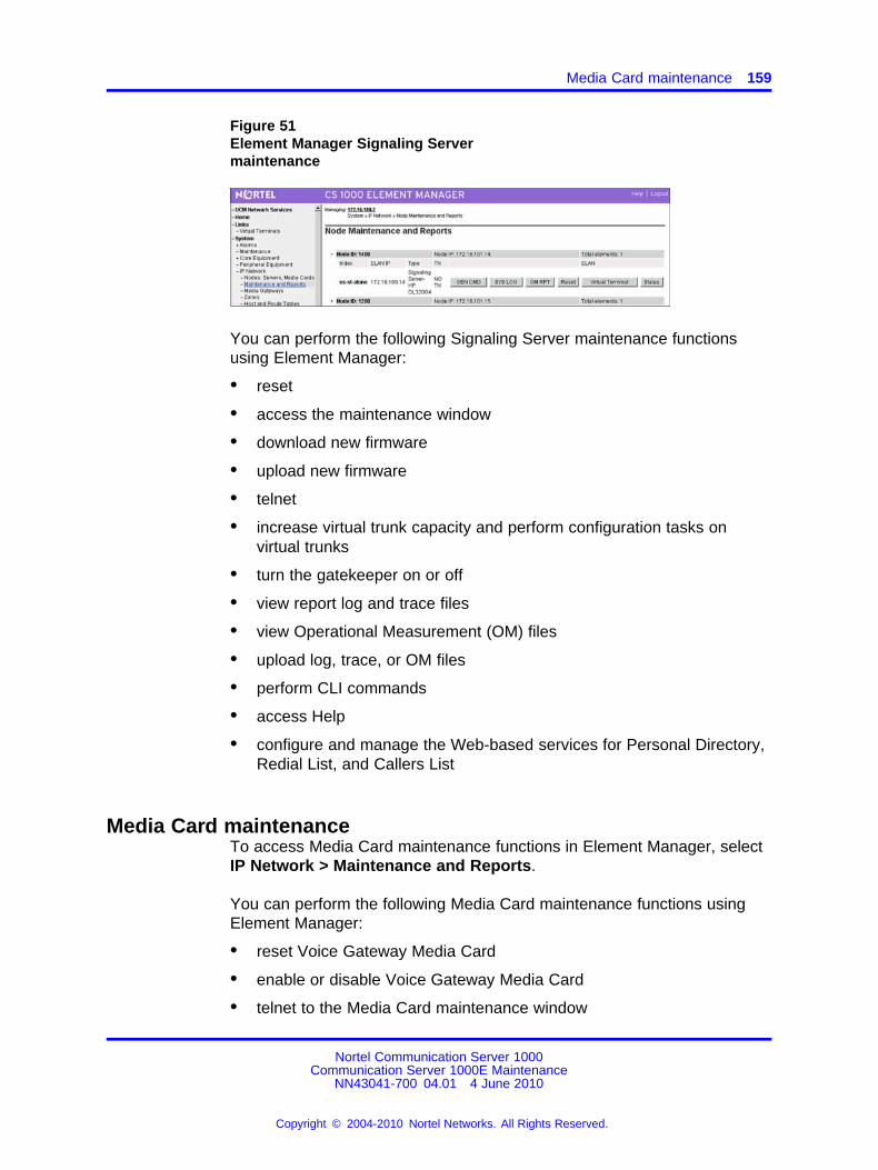
Media Card maintenance 159
Figure 51Element Manager Signaling Servermaintenance
You can perform the following Signaling Server maintenance functionsusing Element Manager:
• reset
• access the maintenance window
• download new firmware
• upload new firmware
• telnet
• increase virtual trunk capacity and perform configuration tasks onvirtual trunks
• turn the gatekeeper on or off
• view report log and trace files
• view Operational Measurement (OM) files
• upload log, trace, or OM files
• perform CLI commands
• access Help
• configure and manage the Web-based services for Personal Directory,Redial List, and Callers List
Media Card maintenanceTo access Media Card maintenance functions in Element Manager, selectIP Network > Maintenance and Reports.
You can perform the following Media Card maintenance functions usingElement Manager:
• reset Voice Gateway Media Card
• enable or disable Voice Gateway Media Card
• telnet to the Media Card maintenance window
Nortel Communication Server 1000Communication Server 1000E Maintenance
NN43041-700 04.01 4 June 2010
Copyright © 2004-2010 Nortel Networks. All Rights Reserved.
.
160 Element Manager
• download loadware and firmware for upgrades
• view individual DSPs
• view or upload Operational Measurement (OM) data
• access Help
• install and uninstall patches
You can reinstall Media Card software by using Deployment Manager. Forinformation about Deployment Manager, see Linux Platform Base andApplications Installation and Commissioning NN43001-315.
LD 36 analog trunk card statusThe STAT command in LD 36 provides status for all analog trunk cardswithin the system. The card number prints before the list of units.
Sample output of LD 36 with the STAT command:
CARD 1UNIT 00 = DSBL (TRK)(TIE LDR IMM/IMM)UNIT 01 = UNEQUNIT 02 = DSBL (TRK)(TIE LDR IMM/IMM)UNIT 03 = UNEQUNIT 04 = UNEQUNIT 05 = DSBL (TRK)(DID LDR IMM/IMM)UNIT 06 = UNEQUNIT 07 = DSBL (TRK)(TIE LDR IMM/IMM)
Nortel Communication Server 1000Communication Server 1000E Maintenance
NN43041-700 04.01 4 June 2010
Copyright © 2004-2010 Nortel Networks. All Rights Reserved.
.
161.
Media Card maintenance
ContentsThis section contains the following topics:
• “Introduction” (page 161)
• “Faceplate maintenance display codes” (page 161)
• “Replacing a Media Card” (page 166)
• “Verify Media Card software and firmware” (page 167)
• “IP Line and IP Phone maintenance and diagnostics” (page 167)
• “IP line shell commands” (page 168)
• “Invoking alarm and log files” (page 169)
• “Media Card 32S and DSP daughterboard DSP tests” (page 169)
IntroductionThis chapter provides information about the maintenance functions of theMedia Card.
Check the Nortel web site for information about the latest software,firmware and application releases. See IP Line Fundamentals forverification steps.
Faceplate maintenance display codesThe Media Card maintenance display provides the diagnostic status ofthe card during power-up, its operational state when in service, and errorinformation on the functional state of the card.
During power-up, the card performs multiple self-tests, including:
• internal RAM test
• ALU test
• address mode test
Nortel Communication Server 1000Communication Server 1000E Maintenance
NN43041-700 04.01 4 June 2010
Copyright © 2004-2010 Nortel Networks. All Rights Reserved.
.
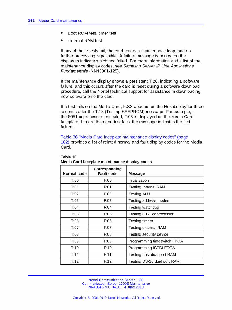
162 Media Card maintenance
• Boot ROM test, timer test
• external RAM test
If any of these tests fail, the card enters a maintenance loop, and nofurther processing is possible. A failure message is printed on thedisplay to indicate which test failed. For more information and a list of themaintenance display codes, see Signaling Server IP Line ApplicationsFundamentals (NN43001-125).
If the maintenance display shows a persistent T:20, indicating a softwarefailure, and this occurs after the card is reset during a software downloadprocedure, call the Nortel technical support for assistance in downloadingnew software onto the card.
If a test fails on the Media Card, F:XX appears on the Hex display for threeseconds after the T:13 (Testing SEEPROM) message. For example, ifthe 8051 coprocessor test failed, F:05 is displayed on the Media Cardfaceplate. If more than one test fails, the message indicates the firstfailure.
Table 36 "Media Card faceplate maintenance display codes" (page162) provides a list of related normal and fault display codes for the MediaCard.
Table 36Media Card faceplate maintenance display codes
Normal codeCorresponding
Fault code Message
T:00 F:00 Initialization
T:01 F:01 Testing Internal RAM
T:02 F:02 Testing ALU
T:03 F:03 Testing address modes
T:04 F:04 Testing watchdog
T:05 F:05 Testing 8051 coprocessor
T:06 F:06 Testing timers
T:07 F:07 Testing external RAM
T:08 F:08 Testing security device
T:09 F:09 Programming timeswitch FPGA
T:10 F:10 Programming ISPDI FPGA
T:11 F:11 Testing host dual port RAM
T:12 F:12 Testing DS-30 dual port RAM
Nortel Communication Server 1000Communication Server 1000E Maintenance
NN43041-700 04.01 4 June 2010
Copyright © 2004-2010 Nortel Networks. All Rights Reserved.
.
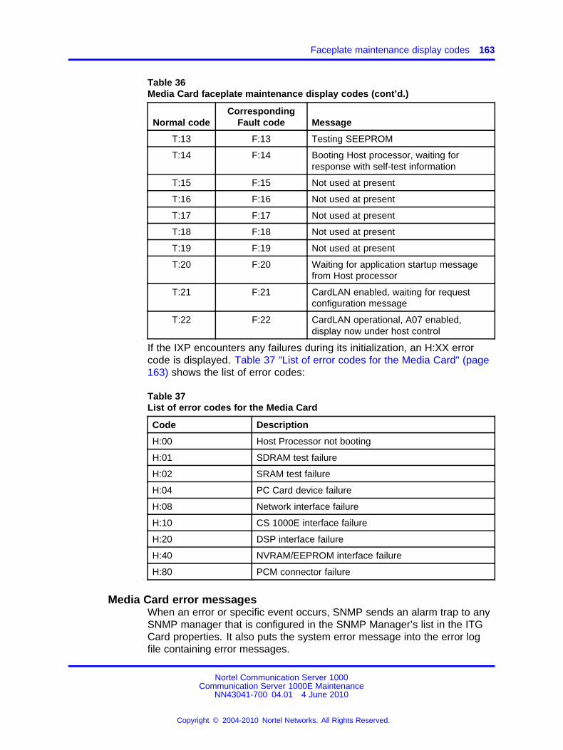
Faceplate maintenance display codes 163
Table 36Media Card faceplate maintenance display codes (cont’d.)
Normal codeCorresponding
Fault code Message
T:13 F:13 Testing SEEPROM
T:14 F:14 Booting Host processor, waiting forresponse with self-test information
T:15 F:15 Not used at present
T:16 F:16 Not used at present
T:17 F:17 Not used at present
T:18 F:18 Not used at present
T:19 F:19 Not used at present
T:20 F:20 Waiting for application startup messagefrom Host processor
T:21 F:21 CardLAN enabled, waiting for requestconfiguration message
T:22 F:22 CardLAN operational, A07 enabled,display now under host control
If the IXP encounters any failures during its initialization, an H:XX errorcode is displayed. Table 37 "List of error codes for the Media Card" (page163) shows the list of error codes:
Table 37List of error codes for the Media Card
Code Description
H:00 Host Processor not booting
H:01 SDRAM test failure
H:02 SRAM test failure
H:04 PC Card device failure
H:08 Network interface failure
H:10 CS 1000E interface failure
H:20 DSP interface failure
H:40 NVRAM/EEPROM interface failure
H:80 PCM connector failure
Media Card error messagesWhen an error or specific event occurs, SNMP sends an alarm trap to anySNMP manager that is configured in the SNMP Manager’s list in the ITGCard properties. It also puts the system error message into the error logfile containing error messages.
Nortel Communication Server 1000Communication Server 1000E Maintenance
NN43041-700 04.01 4 June 2010
Copyright © 2004-2010 Nortel Networks. All Rights Reserved.
.
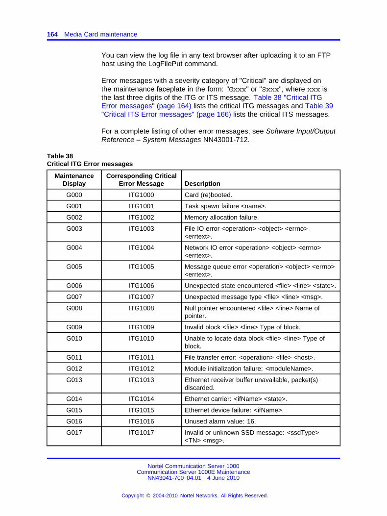
164 Media Card maintenance
You can view the log file in any text browser after uploading it to an FTPhost using the LogFilePut command.
Error messages with a severity category of "Critical" are displayed onthe maintenance faceplate in the form: "Gxxx" or "Sxxx", where xxx isthe last three digits of the ITG or ITS message. Table 38 "Critical ITGError messages" (page 164) lists the critical ITG messages and Table 39"Critical ITS Error messages" (page 166) lists the critical ITS messages.
For a complete listing of other error messages, see Software Input/OutputReference – System Messages NN43001-712.
Table 38Critical ITG Error messages
MaintenanceDisplay
Corresponding CriticalError Message Description
G000 ITG1000 Card (re)booted.
G001 ITG1001 Task spawn failure <name>.
G002 ITG1002 Memory allocation failure.
G003 ITG1003 File IO error <operation> <object> <errno><errtext>.
G004 ITG1004 Network IO error <operation> <object> <errno><errtext>.
G005 ITG1005 Message queue error <operation> <object> <errno><errtext>.
G006 ITG1006 Unexpected state encountered <file> <line> <state>.
G007 ITG1007 Unexpected message type <file> <line> <msg>.
G008 ITG1008 Null pointer encountered <file> <line> Name ofpointer.
G009 ITG1009 Invalid block <file> <line> Type of block.
G010 ITG1010 Unable to locate data block <file> <line> Type ofblock.
G011 ITG1011 File transfer error: <operation> <file> <host>.
G012 ITG1012 Module initialization failure: <moduleName>.
G013 ITG1013 Ethernet receiver buffer unavailable, packet(s)discarded.
G014 ITG1014 Ethernet carrier: <ifName> <state>.
G015 ITG1015 Ethernet device failure: <ifName>.
G016 ITG1016 Unused alarm value: 16.
G017 ITG1017 Invalid or unknown SSD message: <ssdType><TN> <msg>.
Nortel Communication Server 1000Communication Server 1000E Maintenance
NN43041-700 04.01 4 June 2010
Copyright © 2004-2010 Nortel Networks. All Rights Reserved.
.
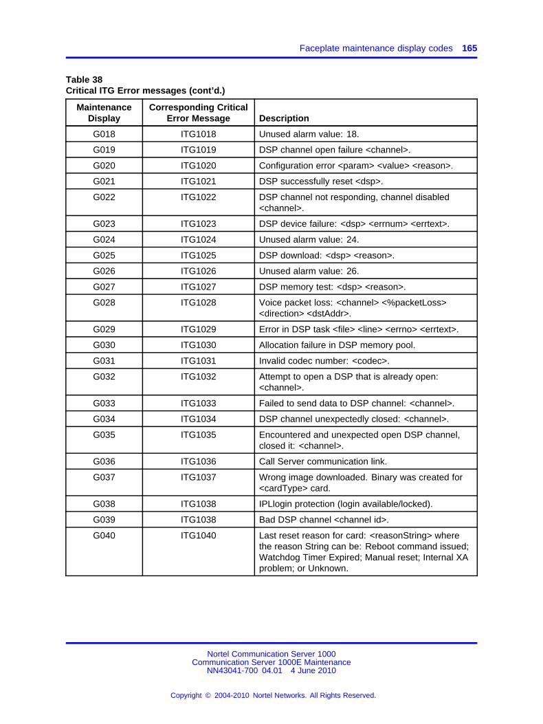
Faceplate maintenance display codes 165
Table 38Critical ITG Error messages (cont’d.)
MaintenanceDisplay
Corresponding CriticalError Message Description
G018 ITG1018 Unused alarm value: 18.
G019 ITG1019 DSP channel open failure <channel>.
G020 ITG1020 Configuration error <param> <value> <reason>.
G021 ITG1021 DSP successfully reset <dsp>.
G022 ITG1022 DSP channel not responding, channel disabled<channel>.
G023 ITG1023 DSP device failure: <dsp> <errnum> <errtext>.
G024 ITG1024 Unused alarm value: 24.
G025 ITG1025 DSP download: <dsp> <reason>.
G026 ITG1026 Unused alarm value: 26.
G027 ITG1027 DSP memory test: <dsp> <reason>.
G028 ITG1028 Voice packet loss: <channel> <%packetLoss><direction> <dstAddr>.
G029 ITG1029 Error in DSP task <file> <line> <errno> <errtext>.
G030 ITG1030 Allocation failure in DSP memory pool.
G031 ITG1031 Invalid codec number: <codec>.
G032 ITG1032 Attempt to open a DSP that is already open:<channel>.
G033 ITG1033 Failed to send data to DSP channel: <channel>.
G034 ITG1034 DSP channel unexpectedly closed: <channel>.
G035 ITG1035 Encountered and unexpected open DSP channel,closed it: <channel>.
G036 ITG1036 Call Server communication link.
G037 ITG1037 Wrong image downloaded. Binary was created for<cardType> card.
G038 ITG1038 IPLlogin protection (login available/locked).
G039 ITG1038 Bad DSP channel <channel id>.
G040 ITG1040 Last reset reason for card: <reasonString> wherethe reason String can be: Reboot command issued;Watchdog Timer Expired; Manual reset; Internal XAproblem; or Unknown.
Nortel Communication Server 1000Communication Server 1000E Maintenance
NN43041-700 04.01 4 June 2010
Copyright © 2004-2010 Nortel Networks. All Rights Reserved.
.
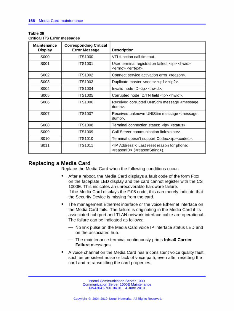
166 Media Card maintenance
Table 39Critical ITS Error messages
MaintenanceDisplay
Corresponding CriticalError Message Description
S000 ITS1000 VTI function call timeout.
S001 ITS1001 User terminal registration failed. <ip> <hwid><errno> <errtext>.
S002 ITS1002 Connect service activation error <reason>.
S003 ITS1003 Duplicate master <node> <ip1> <ip2>.
S004 ITS1004 Invalid node ID <ip> <hwid>.
S005 ITS1005 Corrupted node ID/TN field <ip> <hwid>.
S006 ITS1006 Received corrupted UNIStim message <messagedump>.
S007 ITS1007 Received unknown UNIStim message <messagedump>.
S008 ITS1008 Terminal connection status: <ip> <status>.
S009 ITS1009 Call Server communication link:<state>.
S010 ITS1010 Terminal doesn’t support Codec:<ip><codec>.
S011 ITS1011 <IP Address>: Last reset reason for phone:<reasonID> (<reasonString>).
Replacing a Media CardReplace the Media Card when the following conditions occur:
• After a reboot, the Media Card displays a fault code of the form F:xxon the faceplate LED display and the card cannot register with the CS1000E. This indicates an unrecoverable hardware failure.If the Media Card displays the F:08 code, this can merely indicate thatthe Security Device is missing from the card.
• The management Ethernet interface or the voice Ethernet interface onthe Media Card fails. The failure is originating in the Media Card if itsassociated hub port and TLAN network interface cable are operational.The failure can be indicated as follows:
— No link pulse on the Media Card voice IP interface status LED andon the associated hub.
— The maintenance terminal continuously prints lnIsa0 CarrierFailure messages.
• A voice channel on the Media Card has a consistent voice quality fault,such as persistent noise or lack of voice path, even after resetting thecard and retransmitting the card properties.
Nortel Communication Server 1000Communication Server 1000E Maintenance
NN43041-700 04.01 4 June 2010
Copyright © 2004-2010 Nortel Networks. All Rights Reserved.
.

IP Line and IP Phone maintenance and diagnostics 167
To replace a Media Card, see IP Line Fundamentals
Verify Media Card software and firmwareTo verify the Media Card software and firmware, see IP LineFundamentals
IP Line and IP Phone maintenance and diagnosticsFor Nortel IP Phones, there are two kinds of Terminal Numbers (TNs) toconsider:
• A physical TN, which represents a physical unit of the Media Card.
• A virtual TN, which is configured on a virtual superloop and representsan IP Phone.
The physical TNs are seen as trunk units and are managed using existingLD 32 commands. These commands do not apply to virtual TNs. UseElement Manager for virtual TN maintenance. See Element ManagerSystem Reference – AdministrationNN43001-632 for details.
LD 32 supports STAT, DISU, ENLU, and IDU commands on an IP Phonevirtual TN. All other commands generate an NPR047 message.
The IDU command provides the usual information, such as:
• TN
• TNID
• NT code
• color code
• release code
• serial number
• IP address of the IP Phone
• IP address of the Media Card that acts as the terminal proxy
The serial number is the last three bytes of the IP Phone’s MAC address,printed in ASCII hex format.
Because the system must obtain the requested information from the IPPhone, IDU is effectively a "ping" command. Consequently, it can be usedto test the end-to-end IP connectivity of the IP Phone.
If the IP Phone is not registered with the CS 1000E, an NPR0048message is generated. If the IP Phone is registered but idle, the systemprints the IP Phone IP address and Media Card IP address and generatesan NPR0053 message.
Nortel Communication Server 1000Communication Server 1000E Maintenance
NN43041-700 04.01 4 June 2010
Copyright © 2004-2010 Nortel Networks. All Rights Reserved.
.
168 Media Card maintenance
For additional information on the output format of the IDU command in LD32 and the maintenance commands in LD 32 for the IP Phone, see IP LineFundamentals.
Lamp AuditThe Lamp Audit function provides a continuous source of heartbeatmessages to ensure the IP Phone is powered and the IP connection isactive. Because there is a reliable UDP connection from the Call Serverto the IP Phones, any failure in the IP Phones, or the IP connections isdetected. In addition to Lamp Audit, Network Signaling Diagnostics can berun as part of the midnight routines.
IP line shell commandsThe IP Line shell commands are designed to supplement overlaycommands and to manage features specific to the IP Line platform.
The IP Line shell commands are accessed by connecting a TTY to theMAINT port on the Media Card faceplate.
Commands are grouped into six categories:
• General purpose commands
• File transfer commands
• IP configuration commands
• Reset commands
• DSP commands
To view a list of the ITG shell commands applicable to the Media Card seeIP Line Fundamentals.
Warm rebooting the Media CardTo warm reboot an out-of-service Media Card, use the following IP Lineshell command:cardReset
Media Card DSP testsAt the IP Line shell, you can perform the following DSP tests:
• To run a self-test on the DSP daughterboard, typeDSPselfTestIf the self-test fails, replace the Media Card.
• To run or stop a PCM loopback test, typeDSPPcmLpbkTestOn or DSPPcmLpbkTestOff
Nortel Communication Server 1000Communication Server 1000E Maintenance
NN43041-700 04.01 4 June 2010
Copyright © 2004-2010 Nortel Networks. All Rights Reserved.
.
Media Card 32S and DSP daughterboard DSP tests 169
• To run or stop a Send loopback test, type:DSPSndLpbkTestOn or DSPSndLpbkTestOff
• To run or stop a Receive loopback test, typeDSPRcvLpbkTestOn or DSPRcvLpbkTestOff
Invoking alarm and log filesAlarm and log file output is turned on using the IP Line shell. The followingcommands are entered at the IP Line shell prompt:
• To turn on/off the error log file, type: logFileOn or logFileOff.
• To display the modes of all log files/alarms, type: logFileShow.
Media Card 32S and DSP daughterboard DSP testsMedia Card 32S and DSP daughterboards have new commands that canbe accessed with the OAM and PDT2 shells.
At the OAM shell, you can perform the following DSP tests:
• To run a basic hardware DSP self-test, typedsphwcheckIf the self-test fails, reseat or replace the Media Card or DSPdaughterboard.
• To run a DSP loopback test, typedsplooptest [channel1 channel2]
• To list the state of each channel on the DSP, typedspchanstateshow
• To display the number of channels for each DSP, typedspnumshow
At the PDT2 shell, you can perform the following PCM tests
• To start a PCM capture for a specific channel, streaming the output tothe supplied destination IP address, typepcmcapturestart [channel IP address]
• To stop a PCM capture, typepcmcapturestop
Nortel Communication Server 1000Communication Server 1000E Maintenance
NN43041-700 04.01 4 June 2010
Copyright © 2004-2010 Nortel Networks. All Rights Reserved.
.
170 Media Card maintenance
Nortel Communication Server 1000Communication Server 1000E Maintenance
NN43041-700 04.01 4 June 2010
Copyright © 2004-2010 Nortel Networks. All Rights Reserved.
.
171.
Proactive Voice Quality Management
ContentsThis section contains the following topics:
• “Introduction” (page 171)
• “How voice quality monitoring works” (page 173)
• “Feature packaging” (page 175)
• “Supported system types” (page 175)
• “Feature implementation” (page 175)
• “LD 117 Print zone QoS IP statistics” (page 175)
• “LD 117 Configure voice-quality metric thresholds” (page 175)
• “LD 117 Print voice-quality metric thresholds” (page 177)
• “LD 117 Configure voice-quality sampling (polling)” (page 177)
• “LD 117 Configure zone alarm-notification levels” (page 177)
• “LD 117 Print zone alarm-notification levels” (page 179)
• “Diagnosing and isolating voice-quality problems” (page 179)
• “SNMP interface” (page 180)
• “Heterogeneous environments” (page 180)
IntroductionCS 1000E systems, that are equipped with Voice Gateway Media Cardsrunning IP Line 4.0 or later, support Proactive Voice Quality Management(PVQM). PVQM includes the following capabilities for UNIStim IP Phones.
ATTENTIONThese capabilities are not applicable to SIP sets.
Nortel Communication Server 1000Communication Server 1000E Maintenance
NN43041-700 04.01 4 June 2010
Copyright © 2004-2010 Nortel Networks. All Rights Reserved.
.
172 Proactive Voice Quality Management
• Monitoring of voice quality metrics (latency, jitter, packet loss, andR-Value) for IP Phones and gateway endpoints.R-Value monitoring is available on Phase 2 IP Phones only.
• Two levels of voice quality alarms (Warning and Unacceptable).Alarm thresholds, configured in LD 117, are used to classify systemperformance as good, poor, and unacceptable.This is available on Phase 2 IP Phones only.
• SNMP alarm generation when voice quality metric thresholds areviolated based on a call or bandwidth zone.
• Controlling the number of voice-quality-related SNMP alarms. Thisis performed zone-by-zone by configuring zone alarm notification inLD 117. Alarm control assists in isolating voice quality problems andreducing network traffic.
• Recording of voice quality metric threshold violations, accessible in IPPhone Zone Traffic Report 16 (LD 2) and SNMP MIB.IP Phone Zone Traffic Report 16 (TFS016) includes peg countsfor both alarm levels (Warning and Unacceptable) when recordingthreshold violations for latency, jitter, and packet loss. R-Value islimited to one peg count: Unacceptable.
• R-Value information, available in Operational Measurement (OM)reports. OM reports contain hourly summary of voice quality metricsand endpoint registration activity.
• Network diagnostic utilities to identify, isolate, and report networkproblems affecting voice quality. The diagnostic utilities are availableby using the Command Line Interface (CLI) or IP Phones with Phase2 software.
Network diagnostic utilities includes the following:
— Ping
— Traceroute
— Ethernet statistics
— IP Network statistics
— UNIStim/Reliable User Data Protocol (RUDP) statistics
— Real-Time Control Protocol (RTCP) statistics
— Dynamic Host Control Protocol (DHCP) data
Nortel Communication Server 1000Communication Server 1000E Maintenance
NN43041-700 04.01 4 June 2010
Copyright © 2004-2010 Nortel Networks. All Rights Reserved.
.
How voice quality monitoring works 173
How voice quality monitoring worksPVQM monitors voice quality by polling IP endpoints during and at the endof a call to sample the following voice-quality metrics:
• Latency - length of time, in seconds, for information to travel throughthe network
• Jitter - the variability in latency, in seconds
• Packet Loss - number of packets lost during transmission, inpercentage
• R-Value - measurement of listening R-Value using ITU E-Model.R-Value maps to Mean Opinion Score (MOS).
The sampled metrics are compared to user-configured thresholds todetermine system performance. When sampled metrics exceed configuredthresholds, the system generates statistics.
For details about configuring metric thresholds, see “LD 117 Configurevoice-quality metric thresholds” (page 175).
The Signaling Server collect statistics for each metric to create a QualityDetail Report (QDR). The QDR summarizes metric threshold violationsinto one of the following categories:
• Warning
• Unacceptable
Each summarized QDR record is added to the IP Phone Zone TrafficReport 16 (TFS016). The TFS016 report summarizes by zone the voicequality over the reporting period to allow the administrator to view theoverall voice quality. For more information about TFS016, see TrafficMeasurement: Formats and Outputs Reference .
An SNMP alarm is generated when a voice quality metric thresholdexceeds Warning or Unacceptable status. For details about controllingthe number of SNMP alarms generated, see “LD 117 Configure zonealarm-notification levels” (page 177).
Figure 52 "Voice quality monitoring flow diagram" (page 174) illustratesPVQM within the Voice over IP (VoIP) system.
Nortel Communication Server 1000Communication Server 1000E Maintenance
NN43041-700 04.01 4 June 2010
Copyright © 2004-2010 Nortel Networks. All Rights Reserved.
.

174 Proactive Voice Quality Management
Figure 52Voice quality monitoring flow diagram
Legend
1. IP Phones and endpoints are polled during a call and at the end of acall to extract voice-quality statistics.
2. Statistics for each metric are collected on the Signaling Server or VoiceGateway Media Card.
3. Voice-quality statistics are compared to threshold settings and a QDRis created.
4. The QDR is forwarded to the Call Server for reporting purposes.
5. An SNMP alarm is generated when a voice-quality metric exceeds theWarning or Unacceptable threshold.
Nortel Communication Server 1000Communication Server 1000E Maintenance
NN43041-700 04.01 4 June 2010
Copyright © 2004-2010 Nortel Networks. All Rights Reserved.
.
Feature implementation 175
Feature packagingTo monitor the R-Value audio-quality metric, the Proactive Voice QualityManagement (PVQM) package 401 is required. Monitoring of all othervoice-quality metrics is available with base CS 1000 Release 7.0 software.
Supported system typesCS 1000E systems, that are equipped with Voice Gateway Media Cardsrunning IP Line 4.0, support PVQM.
Feature implementationTo implement this feature, you must install the PVQM_401 softwarepackage.
Task summary listFollowing is a summary of tasks in this section:
“LD 117 Print zone QoS IP statistics” (page 175)“LD 117 Configure voice-quality metric thresholds” (page 175)“LD 117 Print voice-quality metric thresholds” (page 177)“LD 117 Configure voice-quality sampling (polling)” (page 177)“LD 117 Configure zone alarm-notification levels” (page 177)“LD 117 Print zone alarm-notification levels” (page 179)
LD 117 Print zone QoS IP statisticsDisplay QoS IP statistics for zones, ordered by attribute or by zone, in LD117. Traffic Report 16 contains similar information and a list of attributes.For more details about traffic reports, see Traffic Measurement: Formatsand Outputs Reference .
Table 40LD 117 Print zone QoS IP statistics
Command Description
AQOS <attribute> <zone> Print QoS IP statistics by attribute for a specific zone.
AQOS <attribute> ALL Print QoS IP statistics by attribute for all zones.
ZQOS <zone> <attribute> Print QoS IP statistics by zone for a specific attribute.
ZQOS <zone> ALL Print QoS IP statistics by zone for all attributes.
LD 117 Configure voice-quality metric thresholdsTo configure voice-quality metric thresholds based on a call or zone inLD 117, see Table 41 "LD 117 Configure voice-quality metric thresholds"(page 176).
Nortel Communication Server 1000Communication Server 1000E Maintenance
NN43041-700 04.01 4 June 2010
Copyright © 2004-2010 Nortel Networks. All Rights Reserved.
.
176 Proactive Voice Quality Management
Table 41LD 117 Configure voice-quality metric thresholds
Command Description
CHG CQWTH <WarnJitter><WarnLatency><WarnPacketLoss><WarnRFactor>
Change voice-quality Warning thresholds on a per-call basisWhere:<WarnJitter> = 5-(20)-200 msec<WarnLatency> = 5-(40)-100 msec<WarnPacketLoss> = 5-(20)-100 in units [1/10 of a percent]For example, 10 means 1%<WarnRFactor> = 20-(65)-94
CHG CQUTH <UnacceptJitter><UnacceptLatency><UnacceptPacketLoss><UnacceptRFactor>
Change voice-quality Unacceptable thresholds on a per-call basisWhere:<UnacpJitter> = 5-(40)-500 msec<UnacpLatency> = 5-(100)-500 msec<UnacpPacketLoss> = 5-(70)-250 in units [1/10 of a percent]For example, 10 means 1%<UnacpRFactor> = 20-(60)-94
CHG ZQWTH <WarnJitter><WarnLatency><WarnPacketLoss><WarnRFactor>
Change voice-quality Warning thresholds on a zone basisWhere:<WarnJitter> = 0-(20)-100%<WarnLatency> = 0-(20)-100%<WarnPacketLoss> = 0-(20)-100%<WarnRFactor> = 0-(20)-100%
CHG ZQUTH <UnacceptJitter><UnacceptLatency><UnacceptPacketLoss><UnacceptRFactor>
Change voice-quality Unacceptable thresholds on a zone basisWhere:<UnacpJitter> = 0-(2)-100%<UnacpLatency> = 0-(2)-100%<UnacpPacketLoss> = 0-(2)-100%<UnacpRFactor> = 0-(2)-100%
To configure voice-quality metric thresholds using Element Manager,select IP Network > QoS Thresholds from the System menu of theElement Manager navigator bar.
ATTENTIONChanges to threshold values do not propagate to the Signaling Server until youperform a datadump.
Nortel Communication Server 1000Communication Server 1000E Maintenance
NN43041-700 04.01 4 June 2010
Copyright © 2004-2010 Nortel Networks. All Rights Reserved.
.

Feature implementation 177
LD 117 Print voice-quality metric thresholds
Table 42LD 117 Print voice-quality metric thresholds
Command Description
PRT QSTHS Print all voice-quality thresholds
LD 117 Configure voice-quality sampling (polling)To configure the sampling (polling) period, zone alarm-rate collectionwindow, and the minimum number of samples to collect during the window,see Table 43 "LD 117 Configure voice-quality sampling (polling)" (page177).
To configure voice-quality sampling using Element Manager, select IPNetwork > QoS Thresholds from the System menu of the ElementManager navigator bar.
Table 43LD 117 Configure voice-quality sampling (polling)
Command Description
CHG SQOS <SamplePeriod><SampleRateWindow><MinSampleCnt>
Change voice-quality sampling parametersWhere:<SamplePeriod> = 5-(30)-60<SampleRateWindow> = 60-(300)-3600 seconds<MinSampleCnt> = 50-(100)-1000
LD 117 Configure zone alarm-notification levelsSystems that process a large number of calls potentially generate asignificant number of SNMP alarms. Controlling the number of alarmsby configuring zone alarm-notification levels helps isolate voice-qualityproblems and reduce network traffic.
Voice-quality threshold alarms are examined for their severity relative tothe alarm-notification level settings. If the voice-quality threshold alarmseverity exceeds the configured notification level, it generates an SNMPalarm. Otherwise it is suppressed.
You can configure Voice-quality threshold alarm-notification levels by zoneso that some bandwidth zones can be monitored for all alarms and otherzones report only serious voice-quality problems. Alarm-notification levelsare defined in Table 44 "Voice-quality threshold alarm-notification levels"(page 178).
Nortel Communication Server 1000Communication Server 1000E Maintenance
NN43041-700 04.01 4 June 2010
Copyright © 2004-2010 Nortel Networks. All Rights Reserved.
.
178 Proactive Voice Quality Management
Table 44Voice-quality threshold alarm-notification levels
Level Description Alarms
0 All voice-quality alarms are suppressed None
1
Allow zone-based Unacceptable alarms
QOS0017QOS0018QOS0019QOS0020QOS0021
2
Allow all of the preceding pluszone-based Warning alarms
All preceding plusQOS0012QOS0013QOS0014QOS0015QOS0016
3
Allow all preceding plusper-call Unacceptable alarms
All preceding plusQOS0007QOS0008QOS0009QOS0010QOS0011QOS0021QOS0032QOS0033QOS0036QOS0037
4
Allow all preceding plusper-call Warning alarms
All preceding plusQOS0001QOS0002QOS0003QOS0005QOS0006QOS0018QOS0019QOS0022QOS0023QOS0024QOS0025QOS0026QOS0027
To control the number of alarms generated by the system, see Table 45"LD 117 Configure zone alarm-notification levels" (page 179).
Nortel Communication Server 1000Communication Server 1000E Maintenance
NN43041-700 04.01 4 June 2010
Copyright © 2004-2010 Nortel Networks. All Rights Reserved.
.
Diagnosing and isolating voice-quality problems 179
To configure zone alarm-notification levels using Element Manager, selectIP Network > QoS Thresholds from the System menu of the ElementManager navigator bar.
Table 45LD 117 Configure zone alarm-notification levels
Command Description
CHG ZQNL <ZoneNumber> <level> Change the notification level for the specified zoneWhere:<ZoneNumber> = 0–8000<level> = 0-(2)-4
LD 117 Print zone alarm-notification levels
Table 46LD 117 Print zone alarm-notification levels
Command Description
PRT ZQNL <ZoneNumber> Print the notification level for the specified zoneWhere:<ZoneNumber> = 0–8000
Diagnosing and isolating voice-quality problemsTo isolate voice-quality problems, access network diagnostic utilities onan IP Phone. You can run directly the utilities from the IP Phone itself orremotely through a CLI. Diagnostic utilities include the following:
• Ping and Traceroute
Run the Ping or Traceroute command from a specific endpoint with anydestination, typically another endpoint or Signaling Server.
• IP Networking statistics
View information on the packets sent, packets received, broadcastpackets received, multicast packets received, incoming packetsdiscarded, and outgoing packets discarded.
• Ethernet statistics
For an IP Phone on a particular endpoint, view Ethernet statistics,such as number of collisions, VLAN ID, speed, and duplex. The exactstatistics depend on what is available from the IP Phone for the specificendpoint.
• UNISTIM/RUDP statistics
View RUDP statistics for IP Phones, such as number of messages sentor received, retries, resets, and uptime.
• UNIStim Security with DTLS
Nortel Communication Server 1000Communication Server 1000E Maintenance
NN43041-700 04.01 4 June 2010
Copyright © 2004-2010 Nortel Networks. All Rights Reserved.
.

180 Proactive Voice Quality Management
View UNIStim (Lexicon) Security with DTLS statistics for UNIStim IPPhones based on the industry standard DTLS protocol (RFC4347).
• Real time Transport Protocol statistics
While a call is in progress, view RTP/RTCP QoS metrics, such aspacket loss and jitter.
• DHCP
View DHCP settings, such as IP address; and S1, S2, and S4addresses for each IP Phone.
For detailed information about network diagnostic utilities, see IP PhonesFundamentals NN43001-368.
SNMP interfaceSimple Network Management Protocol (SNMP) interfaces with thetraffic-reporting system so that any third-party system, can have a simple,standards-based interface into the system traffic reports.
For details about the SNMP interface, see Communication Server 1000Fault Management – SNMP NN43001-719.
Heterogeneous environmentsIn a heterogeneous environment, with a mixture of Nortel equipment andthird-party equipment, voice-quality monitoring, detection, and alarmingare performed only on IP endpoints that have voice-quality monitoringcapabilities.
For information about IP endpoints and their voice-quality capabilities inthe system, see Table 47 "IP endpoint and voice-quality capabilities" (page180).
Table 47IP endpoint and voice-quality capabilities
Endpoint type Voice-quality monitoring operation
Phase 0 and Phase I IP Phones Detect jitter, packet loss, and latency (when the far end isRTCP-compliant) threshold violations.Polling detects threshold violations. .
Phase 2 IP Phones without PVQMpackage
Detect jitter, packet loss, and latency (when the far end isRTCP-compliant) threshold violations.The IP Phone asynchronously detects threshold violations.
Phase 2 IP Phones with PVQMpackage
Detect jitter, packet loss, and latency (when the far end isRTCP-compliant) and R-Value threshold violations.Threshold violations are detected asynchronously by the IPPhone.
Nortel Communication Server 1000Communication Server 1000E Maintenance
NN43041-700 04.01 4 June 2010
Copyright © 2004-2010 Nortel Networks. All Rights Reserved.
.
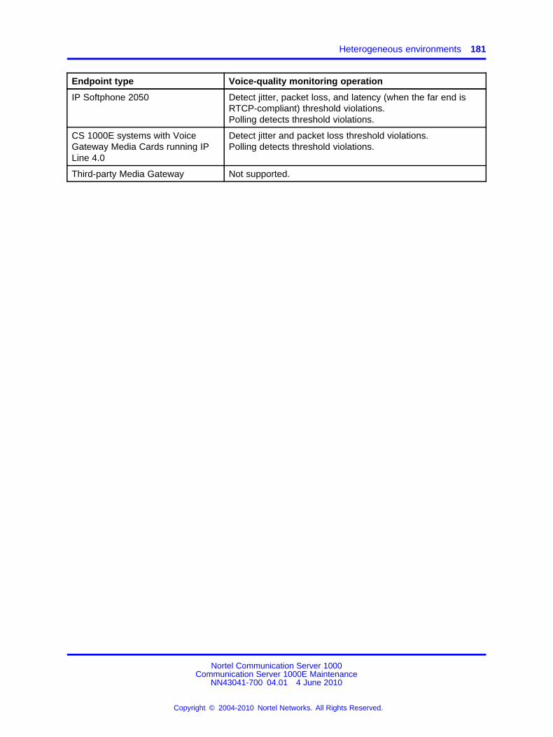
Heterogeneous environments 181
Endpoint type Voice-quality monitoring operation
IP Softphone 2050 Detect jitter, packet loss, and latency (when the far end isRTCP-compliant) threshold violations.Polling detects threshold violations.
CS 1000E systems with VoiceGateway Media Cards running IPLine 4.0
Detect jitter and packet loss threshold violations.Polling detects threshold violations.
Third-party Media Gateway Not supported.
Nortel Communication Server 1000Communication Server 1000E Maintenance
NN43041-700 04.01 4 June 2010
Copyright © 2004-2010 Nortel Networks. All Rights Reserved.
.

182 Proactive Voice Quality Management
Nortel Communication Server 1000Communication Server 1000E Maintenance
NN43041-700 04.01 4 June 2010
Copyright © 2004-2010 Nortel Networks. All Rights Reserved.
.
183.
pbxLink connection
ContentsThis section contains the following topics:
• “Introduction” (page 183)
• “pbxLink connection failure detection” (page 183)
• “LD 117 STAT SERV enhancement” (page 185)
IntroductionpbxLink Connection Failure Detection and status reporting provide thefollowing functionality:
• The pbxLink Connection Failure Detection feature provides a way todetect the link status of Signaling Servers and Voice Gateway MediaCards. An alarm is generated if the pbxLink is not detected after awarm or cold start of the Call Server.
• The STAT SERV command in LD 117 displays the link status of theSignaling Server and Voice Gateway Media Cards that are configuredto connect to the system. The display also provides information aboutthe applications that run on the Signaling Server and Voice GatewayMedia Cards.
pbxLink connection failure detectionThe Call Server, which maintains a list of all known registered elements(Signaling Servers and Voice Gateway Media Cards), monitors thepbxLink. When booted, a Call Server has a 5-minute delay to enable theseknown elements to reestablish contact with the Call Server.
If a known element fails to register with the Call Server, an ELAN0028alarm is generated.
If an unknown Signaling Server registers with the Call Server, anELAN0029 alarm is generated.
Nortel Communication Server 1000Communication Server 1000E Maintenance
NN43041-700 04.01 4 June 2010
Copyright © 2004-2010 Nortel Networks. All Rights Reserved.
.
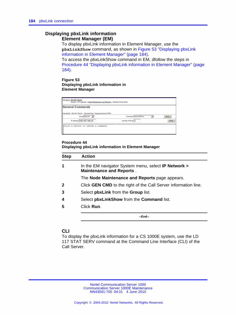
184 pbxLink connection
Displaying pbxLink informationElement Manager (EM)To display pbxLink information in Element Manager, use thepbxLinkShow command, as shown in Figure 53 "Displaying pbxLinkinformation in Element Manager" (page 184).To access the pbxLinkShow command in EM, dfollow the steps inProcedure 44 “Displaying pbxLink information in Element Manager” (page184).
Figure 53Displaying pbxLink information inElement Manager
Procedure 44Displaying pbxLink information in Element Manager
Step Action
1 In the EM navigator System menu, select IP Network >Maintenance and Reports .
The Node Maintenance and Reports page appears.
2 Click GEN CMD to the right of the Call Server information line.
3 Select pbxLink from the Group list.
4 Select pbxLinkShow from the Command list.
5 Click Run.
--End--
CLITo display the pbxLink information for a CS 1000E system, use the LD117 STAT SERV command at the Command Line Interface (CLI) of theCall Server.
Nortel Communication Server 1000Communication Server 1000E Maintenance
NN43041-700 04.01 4 June 2010
Copyright © 2004-2010 Nortel Networks. All Rights Reserved.
.
LD 117 STAT SERV enhancement 185
LD 117 STAT SERV enhancementTo display link-status information for Voice Gateway Media Cards thatare registered to a Call Server you can use the suite of Statistic Services(STAT SERV) commands.
STAT SERV provides consolidated link-status information by applicationtype, IP address, host name, and IP Telephony Node ID.
STAT SERV status information includes the following:
• node ID
• host name
• ELAN IP address
• element role
• platform type
• connection ID
• enabled applications
• registered and unregistered endpoints, such as IP Phones and VoiceGateway Media Cards
• information about the pbxLink and enabled applications
• the Signaling Server resource count
pbxLink informationThe STAT SERV command provides the following pbxLink information:
• the time the pbxLink was last established
• the time the pbxLink was lost, if previously established
• the time the pbxLink last attempted to establish a connection, if thepbxLink failed to establish
• the Signaling Server resource count, which helps to determine thenumber of virtual trunks that you can configure.
Application informationIf an active link to an element is established, the Call Server obtainsinformation about the applications that run on the element.Table 48 "Queried information in STAT SERV" (page 186) lists theapplications and describes the information provided by those applications.
Nortel Communication Server 1000Communication Server 1000E Maintenance
NN43041-700 04.01 4 June 2010
Copyright © 2004-2010 Nortel Networks. All Rights Reserved.
.
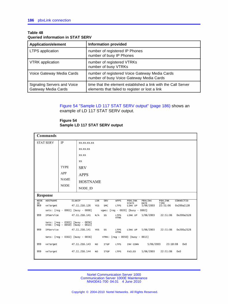
186 pbxLink connection
Table 48Queried information in STAT SERV
Application/element Information provided
LTPS application number of registered IP Phonesnumber of busy IP Phones
VTRK application number of registered VTRKsnumber of busy VTRKs
Voice Gateway Media Cards number of registered Voice Gateway Media Cardsnumber of busy Voice Gateway Media Cards
Signaling Servers and VoiceGateway Media Cards
time that the element established a link with the Call Serverelements that failed to register or lost a link
Figure 54 "Sample LD 117 STAT SERV output" (page 186) shows anexample of LD 117 STAT SERV output.
Figure 54Sample LD 117 STAT SERV output
Nortel Communication Server 1000Communication Server 1000E Maintenance
NN43041-700 04.01 4 June 2010
Copyright © 2004-2010 Nortel Networks. All Rights Reserved.
.
LD 117 STAT SERV enhancement 187
Table 49 "STAT SERV response fields and description" (page 187) listsfield descriptions in the STAT SERV response.
Table 49STAT SERV response fields and description
STAT SERV responsefield
Description
NODE ID The related node.Value is a number from 0 – 9999.
HOSTNAME The alias that the system assigned to the host.Value is a string.
ELANIP The element IP connection to the Call Server.Value is an IP address.
LDR Specifies if the element is the Leader for the related node.Value is YES or NO.
SRV The element type.Values are• SMC – Media Card 32-port card• ITGP – ITG-P 24-port card• SS – Signaling Server
APPS The application running on the element.Values are• LTPS• VTRK
PBXLINK STATE Tthe element current pbxLink state.Values are• LINK UP• LOST• FAILED• INV CONN (element is connected, but its configuration was notfound on the Call Server, which indicates that this element might beconnected to the wrong Call Server)
PBXLINK DATE/TIME When the element pbxLink state last changed.
CONNECTED The element connection ID.
Sets Values are• reg – the number of IP Phones registered to the element• busy – the number of IP Phones that are currently busy
VGWs Values are• reg – the number of voice gateways (DSP resources) areconfigured on the element• busy – the number of voice gateways (DSP resources) areactive/busy on the element
Nortel Communication Server 1000Communication Server 1000E Maintenance
NN43041-700 04.01 4 June 2010
Copyright © 2004-2010 Nortel Networks. All Rights Reserved.
.
188 pbxLink connection
STAT SERV responsefield
Description
VTRK Values are• reg – the number of VTRK channels are configured on the element• busy – the number of VTRK channels are active/busy on theelement
SSRC Signaling Server capacity
Nortel Communication Server 1000Communication Server 1000E Maintenance
NN43041-700 04.01 4 June 2010
Copyright © 2004-2010 Nortel Networks. All Rights Reserved.
.
189.
Technical Assistance service
ContentsThis section contains information on the following topics:
• “Nortel Technical Assistance Centers” (page 189)
• “Services available” (page 191)
• “Requesting assistance” (page 193)
Nortel Technical Assistance CentersTo help customers obtain maximum benefit, reliability, and satisfactionfrom their CS 1000E system s, Nortel provides technical assistance inresolving system problems. Table 50 "Customer Technical Services(CTS)" (page 189) lists the centers that provide this service.
Table 50Customer Technical Services (CTS)
Location Contact
NortelGlobal Enterprise Technical Support(GETS)PO Box 8338582370 Performance DriveRichardson, TX75083 USA
North America
Telephone: 1 800 4NORTEL
Nortel Corp.P.O. Box 4000250 Sydney StreetBelleville, OntarioK8N 5B7 Canada
North America
Telephone: 1 800 4NORTEL
Nortel Communication Server 1000Communication Server 1000E Maintenance
NN43041-700 04.01 4 June 2010
Copyright © 2004-2010 Nortel Networks. All Rights Reserved.
.
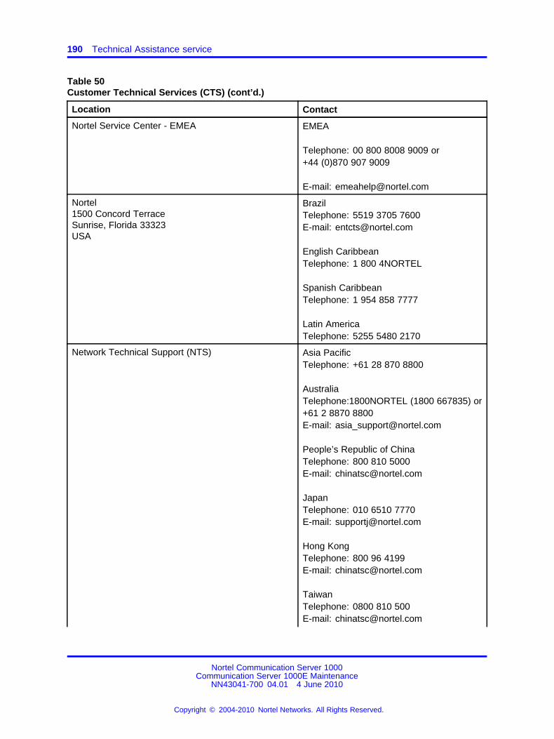
190 Technical Assistance service
Table 50Customer Technical Services (CTS) (cont’d.)
Location Contact
Nortel Service Center - EMEA EMEA
Telephone: 00 800 8008 9009 or+44 (0)870 907 9009
E-mail: [email protected]
Nortel1500 Concord TerraceSunrise, Florida 33323USA
BrazilTelephone: 5519 3705 7600E-mail: [email protected]
English CaribbeanTelephone: 1 800 4NORTEL
Spanish CaribbeanTelephone: 1 954 858 7777
Latin AmericaTelephone: 5255 5480 2170
Network Technical Support (NTS) Asia PacificTelephone: +61 28 870 8800
AustraliaTelephone:1800NORTEL (1800 667835) or+61 2 8870 8800E-mail: [email protected]
People’s Republic of ChinaTelephone: 800 810 5000E-mail: [email protected]
JapanTelephone: 010 6510 7770E-mail: [email protected]
Hong KongTelephone: 800 96 4199E-mail: [email protected]
TaiwanTelephone: 0800 810 500E-mail: [email protected]
Nortel Communication Server 1000Communication Server 1000E Maintenance
NN43041-700 04.01 4 June 2010
Copyright © 2004-2010 Nortel Networks. All Rights Reserved.
.
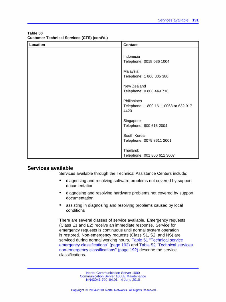
Services available 191
Table 50Customer Technical Services (CTS) (cont’d.)
Location Contact
IndonesiaTelephone: 0018 036 1004
MalaysiaTelephone: 1 800 805 380
New ZealandTelephone: 0 800 449 716
PhilippinesTelephone: 1 800 1611 0063 or 632 9174420
SingaporeTelephone: 800 616 2004
South KoreaTelephone: 0079 8611 2001
Thailand:Telephone: 001 800 611 3007
Services availableServices available through the Technical Assistance Centers include:
• diagnosing and resolving software problems not covered by supportdocumentation
• diagnosing and resolving hardware problems not covered by supportdocumentation
• assisting in diagnosing and resolving problems caused by localconditions
There are several classes of service available. Emergency requests(Class E1 and E2) receive an immediate response. Service foremergency requests is continuous until normal system operationis restored. Non-emergency requests (Class S1, S2, and NS) areserviced during normal working hours. Table 51 "Technical serviceemergency classifications" (page 192) and Table 52 "Technical servicesnon-emergency classifications" (page 192) describe the serviceclassifications.
Nortel Communication Server 1000Communication Server 1000E Maintenance
NN43041-700 04.01 4 June 2010
Copyright © 2004-2010 Nortel Networks. All Rights Reserved.
.
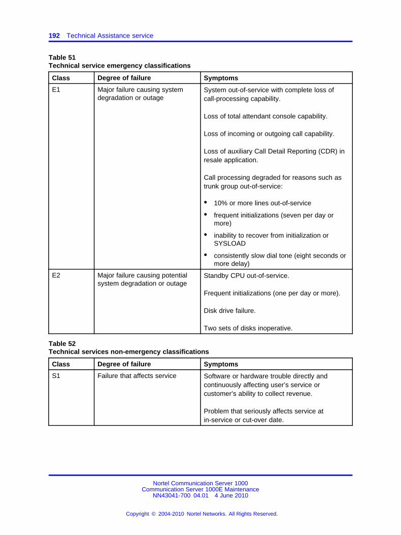
192 Technical Assistance service
Table 51Technical service emergency classifications
Class Degree of failure Symptoms
E1 Major failure causing systemdegradation or outage
System out-of-service with complete loss ofcall-processing capability.
Loss of total attendant console capability.
Loss of incoming or outgoing call capability.
Loss of auxiliary Call Detail Reporting (CDR) inresale application.
Call processing degraded for reasons such astrunk group out-of-service:
• 10% or more lines out-of-service
• frequent initializations (seven per day ormore)
• inability to recover from initialization orSYSLOAD
• consistently slow dial tone (eight seconds ormore delay)
E2 Major failure causing potentialsystem degradation or outage
Standby CPU out-of-service.
Frequent initializations (one per day or more).
Disk drive failure.
Two sets of disks inoperative.
Table 52Technical services non-emergency classifications
Class Degree of failure Symptoms
S1 Failure that affects service Software or hardware trouble directly andcontinuously affecting user’s service orcustomer’s ability to collect revenue.
Problem that seriously affects service atin-service or cut-over date.
Nortel Communication Server 1000Communication Server 1000E Maintenance
NN43041-700 04.01 4 June 2010
Copyright © 2004-2010 Nortel Networks. All Rights Reserved.
.
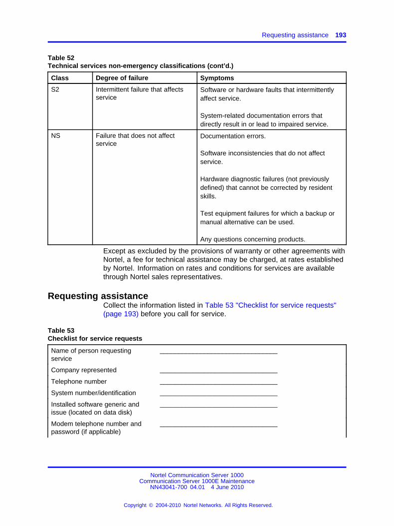
Requesting assistance 193
Table 52Technical services non-emergency classifications (cont’d.)
Class Degree of failure Symptoms
S2 Intermittent failure that affectsservice
Software or hardware faults that intermittentlyaffect service.
System-related documentation errors thatdirectly result in or lead to impaired service.
NS Failure that does not affectservice
Documentation errors.
Software inconsistencies that do not affectservice.
Hardware diagnostic failures (not previouslydefined) that cannot be corrected by residentskills.
Test equipment failures for which a backup ormanual alternative can be used.
Any questions concerning products.
Except as excluded by the provisions of warranty or other agreements withNortel, a fee for technical assistance may be charged, at rates establishedby Nortel. Information on rates and conditions for services are availablethrough Nortel sales representatives.
Requesting assistanceCollect the information listed in Table 53 "Checklist for service requests"(page 193) before you call for service.
Table 53Checklist for service requests
Name of person requestingservice
________________________________
Company represented ________________________________
Telephone number ________________________________
System number/identification ________________________________
Installed software generic andissue (located on data disk)
________________________________
Modem telephone number andpassword (if applicable)
________________________________
Nortel Communication Server 1000Communication Server 1000E Maintenance
NN43041-700 04.01 4 June 2010
Copyright © 2004-2010 Nortel Networks. All Rights Reserved.
.
194 Technical Assistance service
Table 53Checklist for service requests (cont’d.)
Seriousness of request (see Table51 "Technical service emergencyclassifications" (page 192) andTable 52 "Technical servicesnon-emergency classifications"(page 192))
________________________________
Description of assistance required ________________________________
_____________________________________________
_____________________________________________
Nortel Communication Server 1000Communication Server 1000E Maintenance
NN43041-700 04.01 4 June 2010
Copyright © 2004-2010 Nortel Networks. All Rights Reserved.
.
195.
Index
Aalarm
causes 54major 53minor 53remote 54system 53
alarms, system 53analog trunk card status, LD 36 160
BBackground Routine 60backup
Call Server (Element Manager) 157CCBR 102databases 101EDD
CP PIV, CP PM 102bantam jacks 52
Ccall processing
sysload effect on 37, 39system initialization effect on 37,
39, 59Call Server
backup (Element Manager) 157clearing faults 71EDD in Element Manager 158fault indications 76faults 75removing cover 110restore data in Element Manager 158
circuit cardLEDs 46
circuit card, faults 83
circuit card, handling duringmaintenance 18
circuit card, self-test 33circuit card, status indicators 47circuit card, trunk 97circuit cards
replacing 109commands
CHG PDV 96Disable 33Enable 33executing 24IP line shell 168LMAX 61maintenance 58PRT PDV 96
Common Processor Media Gatewayfeatures 43
conference call faults 86connections, LAN, layer 2 and layer 3 95Core Call Server faults 75CP PIV Call Processor card
faceplate LEDs 40CTS, contacting 189
Ddiagnostic programs 58DTLS
Unsuccessful negotiation 62
EEDD
CP PIV, CP PM 102in Element Manager 158
ELAN network interface fault indicators 82Element Manager
Nortel Communication Server 1000Communication Server 1000E Maintenance
NN43041-700 04.01 4 June 2010
Copyright © 2004-2010 Nortel Networks. All Rights Reserved.
.
196
analog trunk card status 160Call Server backup and restore 157Call Server maintenance 155Call Server restore 158description 22media card maintenance 159Signaling Server maintenance 158
error messagesITG 164ITS 166Media Card 163
Ethernet ports100BaseT 47, 9410BaseT 21, 47Activity 47
Ffault clearing process 71fault clearing, with an SDI terminal 97fault, notification 73faults
Call Server 75faults in circuit card 83faults, call transfer 86faults, conference call setup 86faults, Core-to-Expansion 94faults, ELAN network interface 82faults, MG 1000E 83faults, Music-on-Hold 86faults, network, indicators 94
GGateway Controller
system terminal access 21
HHardware maintenance tools 29hex codes
faceplate display 47History File
maintenance display codes 41
IINI (initialization) 59initialize
button 37, 39program 59
Intelligent Peripheral Equipment cards
replacing 149Interactive diagnostics 66IP line maintenance and diagnostics 167IP Line shell commands 168IP Phone maintenance and
diagnostics 167
Jjacks 52
Kkeyboard to dial pad translation 25
LLayer 2 LAN connections 95Layer 3 LAN connections 95LD 117
ping 83QoS 95QoS commands 175stat serv 184
LD 36, analog trunk card status 160LED
Ethernet activity 47maintenance hex display 47media card status 47NT4N39 faceplate 40NTAK09 faceplate 50NTAK10 faceplate 47NTAK79 faceplate 48NTBK50 faceplate 49NTDU64 alarm/fan module 30NTDW60 faceplate 43NTDW61 Active CPU 37NTDW61 Call Server status 37NTDW61 ELAN 38NTDW61 HSP 38NTDW61 Signaling Server status 39NTRB21 faceplate 50
Line transfer 54link faults 82Local access
CS 1000 19
Mmaintaining IP Phones 167Maintenance
telephone 24
Nortel Communication Server 1000Communication Server 1000E Maintenance
NN43041-700 04.01 4 June 2010
Copyright © 2004-2010 Nortel Networks. All Rights Reserved.
.

197
tools 29, 57maintenance commands, executing 23maintenance display codes
/faultsmaintenance display codes 76
maintenance hex display 47maintenance overlays 24maintenance telephone 25maintenance, Media Card 161maintenance, software 57Major alarm 75Media card
replacing 166Media Card
DSP testing 168error messages 163
Media Gateway Controllerfaceplate LEDs 43features 43LDS CLI commands 64local access 64Local Diagnostic Shells 63login banner 63remote access 65
MG 1000E faults 82MG 1000T fault 89MG 1000T, faults 94MG XPEC
features 42Midnight Routine 60monitor jacks 52MTA class of service 24Music-on-Hold, faults 86
Nnetwork fault indicators 94NT4N39 CP PIV Call Processor card
features 39replacing 134
NT4N48 System Utility cardfeatures 40replacing 136
NT4N64 CP PII Call Processor cardfeatures 39
NT5K21 equipment cardreplacing 150
NTAG26 equipment cardreplacing 151
NTAK02replacing 143
NTAK03replacing 144
NTAK09 148faceplate LEDs 50replacing (PRI applications) 147
NTAK10faceplate LEDs 47replacing (DTI applications) 148
NTAK20removing 145replacing 146
NTAK79faceplate LEDs 48replacing 144
NTAK92 protection module 151NTAK93
removing 145replacing 146
NTBK50faceplate LEDs 49removing daughterboards 145replacing 144replacing daughterboards 146
NTBK51removing 145replacing 146
NTDK20CPU or Memory fault 89
NTDU64 alarm/fan moduleLEDs 30replacing 139
NTDU65 power supply modulereplacing 139
NTDU67 Drive Carrier cardreplacing 137
NTDW20 Media Gateway ExtendedPeripheral Equipment Controller(MG XPEC)
features 42NTDW53 Common Processor Dual
Corefeatures 33
NTDW56 Common Processor MediaGateway
NTDW59 Common Processor MediaGateway 43
NTDW60 Media Gateway Controllerfaceplate LEDs 43features 43
Nortel Communication Server 1000Communication Server 1000E Maintenance
NN43041-700 04.01 4 June 2010
Copyright © 2004-2010 Nortel Networks. All Rights Reserved.
.
198
NTDW61 Common Processor PentiumMobile
features 35NTDW61 CP PM Call Processor card
faceplate LEDs 37NTDW61 CP PM Signaling Server
faceplate LEDs 39features 38
NTDW62 DSP daughterboardfeatures 45replacing 133
NTDW64 DSP daughterboardfeatures 45replacing 133
NTDW65 Voice Gateway Media Cardfeatures 46
NTDW78 DSP daughterboardfeatures 45
NTRB21faceplate LEDs 50replacing (DTI applications) 148
OOVD message, trunks 97Overlay Loader 61overlays 58overlays, maintenance 24overload (OVD) message 83Overload Monitor 61
Ppower failures
external power system 55Precautions 17
QQoS
configuresampling 177
configure thresholds 175configure zone alarm notification 177LAN
monitoring 95print thresholds 177print zone alarm notification 179
RRemote access 19
replacing (DTI applications) 148Resident Trunk Diagnostic 61
SSDI port 19Signaling Server
maintenance in Element Manager 158NTDW61 faceplate LEDs 39replacing 127
Software maintenance tools 57SPRE (Special Service Prefix) 24STAD command 72, 106System
accessing 23alarms 53Loader 62messages 74monitor 54terminal 23
system initializationmanual 37, 39
system terminal, using 23
TTechnical Assistance Centers 189Terminal server 19Tools
Hardware maintenance 29Software maintenance 57
trunk cannot make or receive calls 97trunk failure, impact 61trunk, resident diagnostic 61trunks
E and M 97universal 97
Uuniversal trunks 97user reports
for Call Server faults 76
Nortel Communication Server 1000Communication Server 1000E Maintenance
NN43041-700 04.01 4 June 2010
Copyright © 2004-2010 Nortel Networks. All Rights Reserved.
.

Nortel Communication Server 1000
Communication Server 1000E MaintenanceRelease: 7.0Publication: NN43041-700Document revision: 04.01Document release date: 4 June 2010
Copyright © 2004-2010 Nortel Networks. All Rights Reserved.
While the information in this document is believed to be accurate and reliable, except as otherwise expressly agreed to in writingNORTEL PROVIDES THIS DOCUMENT "AS IS" WITHOUT WARRANTY OR CONDITION OF ANY KIND, EITHER EXPRESSOR IMPLIED. The information and/or products described in this document are subject to change without notice.
Nortel, Nortel Networks, the Nortel logo, and the Globemark are trademarks of Nortel Networks.
All other trademarks are the property of their respective owners.
To provide feedback or to report a problem in this document, go to www.nortel.com/documentfeedback.
www.nortel.com


