NI 43-101 Technical DASA Uranium Project, Central...
113
NI 43-101 Technical Report DASA Uranium Project, Central Niger For Global Atomic Fuels Corporation CSA Global Report: Nº R186.2017 31 July 2017 www.csaglobal.com
Transcript of NI 43-101 Technical DASA Uranium Project, Central...

NI 43-101 Technical Report
DASA Uranium Project, Central Niger
For
Global Atomic Fuels
Corporation
CSA Global Report: Nº R186.2017 31 July 2017
www.csaglobal.com
I
GLOBAL ATOMIC FUELS CORPORATION
DASA URANIUM PROJECT, CENTRAL NIGER
CSA-Report Nº: R186.2017
Report prepared for
Client Name Global Atomic Fuels Corporation
Project Name/Job Code DASA-U Uranium Deposit, NI 43-101 Report GAFNIR01
Contact Name George Flach
Contact Title Vice President of Exploration
Office Address 8 King Street West, Suite 1700, Toronto, Ontario, M5C185, Canada
Report issued by
CSA Global Office
CSA Global Pty Ltd Suite 501, 365 Bay Street Toronto, Ontario M5H 2V1 Canada T +1 416 368 7041 E [email protected]
Division Resources
Report information
File name R186.2017 Report Dasa NI FINAL.docx
Last edited 30/04/2017
Report Status Final
Author and Reviewer Signatures
Author Dmitry Pertel Signature:
Co-Author Maxim Seredkin Signature:
Peer Reviewer Daniel Wholley Signature:
CSA Global Authorization
Aaron Meakin
Manager – Resources Signature:
© Copyright 2017

II
GLOBAL ATOMIC FUELS CORPORATION
DASA URANIUM PROJECT, CENTRAL NIGER
CSA-Report Nº: R186.2017
Contents
Report prepared for ............................................................................................................................................ I
Report issued by ................................................................................................................................................. I
Report information ............................................................................................................................................. I
Author and Reviewer Signatures ........................................................................................................................ I
1 SUMMARY ............................................................................................................................................ 1
1.1 Executive Summary ............................................................................................................................. 1
1.2 Conclusions .......................................................................................................................................... 2
1.3 Recommendations ............................................................................................................................... 2
1.4 Technical Summary ............................................................................................................................. 3 1.4.1 Property Description and Location ................................................................................................ 3 1.4.2 Land Tenure ................................................................................................................................... 3 1.4.3 Existing Infrastructure ................................................................................................................... 3 1.4.4 History ........................................................................................................................................... 3 1.4.5 Geology and Mineralization .......................................................................................................... 4 1.4.6 Exploration Status ......................................................................................................................... 4 1.4.7 Mineral Resources ......................................................................................................................... 5
2 INTRODUCTION .................................................................................................................................... 6
2.1 Issuer ................................................................................................................................................... 6
2.2 Terms of Reference ............................................................................................................................. 6
2.3 Qualified Person Property Inspection ................................................................................................. 6
2.4 Sources of Information ........................................................................................................................ 6
3 RELIANCE ON OTHER EXPERTS ............................................................................................................... 7
4 PROPERTY DESCRIPTION AND LOCATION ............................................................................................... 8
4.1 Location of Property ............................................................................................................................ 8
4.2 Mineral Tenure .................................................................................................................................... 8
5 ACCESSIBILITY, CLIMATE, LOCAL RESOURCES, INFRASTRUCTURE AND PHYSIOGRAPHY .......................... 11
5.1 Accessibility ....................................................................................................................................... 11
5.2 Climate............................................................................................................................................... 12
5.3 Physiography ..................................................................................................................................... 12
5.4 Local Resources and Infrastructure ................................................................................................... 13
6 HISTORY ............................................................................................................................................. 14
6.1 Introduction ....................................................................................................................................... 14
6.2 Regional Exploration by the French Nuclear Energy Commission (1957–1981) ............................... 14
6.3 Regional Exploration by PNC and ONAREM (1981–1990) ................................................................. 15
6.4 Exploration Activity from 2007 Onwards .......................................................................................... 15
6.5 Previous Mineral Resource Estimation .............................................................................................. 16
III
GLOBAL ATOMIC FUELS CORPORATION
DASA URANIUM PROJECT, CENTRAL NIGER
CSA-Report Nº: R186.2017
6.6 Production from the Property ........................................................................................................... 16
7 GEOLOGICAL SETTING AND MINERALISATION ...................................................................................... 17
7.1 Introduction ....................................................................................................................................... 17
7.2 Regional Geology ............................................................................................................................... 17
7.3 Structural Setting ............................................................................................................................... 21 7.3.1 South Fault System and N30°E Associated Structures ................................................................ 22 7.3.2 N130-N140°E and N70-N80°E Conjugate Fault System ............................................................... 22 7.3.3 Fold-like Structures ..................................................................................................................... 22
7.4 Property Geology ............................................................................................................................... 23
7.5 Structural Geology of the Property ................................................................................................... 34
7.6 Uranium Mineralization..................................................................................................................... 35
8 DEPOSIT TYPE ..................................................................................................................................... 38
9 EXPLORATION ..................................................................................................................................... 42
9.1 Data Compilation and Old Drillhole Locations ................................................................................... 42
9.2 Radiometric Ground Survey and Geostructural Mapping ................................................................. 43
9.3 Topographic Survey ........................................................................................................................... 45 9.3.1 Ground Control ........................................................................................................................... 45 9.3.2 Aerial Survey ............................................................................................................................... 45
10 DRILLING ............................................................................................................................................ 47
10.1 Geological Exploratory Drilling .......................................................................................................... 47 10.1.1 Drilling Procedures ...................................................................................................................... 48 10.1.2 Drilling Monitoring ...................................................................................................................... 48
10.2 Downhole Survey ............................................................................................................................... 50 10.2.1 Gamma-Ray Logging .................................................................................................................... 50 10.2.2 Downhole Survey ........................................................................................................................ 51 10.2.3 Drillhole Diameter Measurements .............................................................................................. 52 10.2.4 PFN Logging ................................................................................................................................. 52
10.3 Rotary Chips and Core Logging .......................................................................................................... 52 10.3.1 Rotary Chip Logging ..................................................................................................................... 53 10.3.2 Core Logging ................................................................................................................................ 53
10.4 Sampling ............................................................................................................................................ 55
11 SAMPLE PREPARATION, ANALYSES AND SECURITY ............................................................................... 57
11.1 Sample Preparation and Analyses ..................................................................................................... 57
11.2 Specific Gravity Data .......................................................................................................................... 57
11.3 Quality Assurance and Quality Control Programs ............................................................................. 58
11.4 Radioactive Equilibrium Factor .......................................................................................................... 61
11.5 CSA Global Comments ....................................................................................................................... 63
12 DATA VERIFICATION ............................................................................................................................ 64
13 MINERAL PROCESSING AND METALLURGICAL TESTING ......................................................................... 65

IV
GLOBAL ATOMIC FUELS CORPORATION
DASA URANIUM PROJECT, CENTRAL NIGER
CSA-Report Nº: R186.2017
13.1 Comminution ..................................................................................................................................... 65
13.2 Leaching ............................................................................................................................................. 66
13.3 Solid-Liquid Separation ...................................................................................................................... 67
13.4 Solvent Extraction and Ion Exchange ................................................................................................ 67
13.5 Uranium Precipitation ....................................................................................................................... 67
13.6 Tailings Characterization ................................................................................................................... 67
13.7 Metallurgical Testing — Conclusion and Recommendations ............................................................ 68
14 MINERAL RESOURCE ESTIMATES.......................................................................................................... 69
14.1 Software Used ................................................................................................................................... 69
14.2 Database Compilation ....................................................................................................................... 69
14.3 Data Validation .................................................................................................................................. 69
14.4 Exploratory Data Analysis – Statistical Analysis ................................................................................. 70
14.5 Interpretation of Mineralized Bodies ................................................................................................ 72
14.6 Wireframing....................................................................................................................................... 75
14.7 Drillhole Data Selection and Compositing ......................................................................................... 76
14.8 Transformation of Coordinates and Unfolding .................................................................................. 76
14.9 Geostatistical Analysis ....................................................................................................................... 77
14.10 Block Modelling ................................................................................................................................. 79
14.11 Grade Interpolation ........................................................................................................................... 79
14.12 Density Values ................................................................................................................................... 80
14.13 Mineral Resource Classification Strategy .......................................................................................... 80
14.14 Block Model Validation ...................................................................................................................... 81
14.15 Mineral Resource Report ................................................................................................................... 84
15 MINERAL RESERVE ESTIMATES ............................................................................................................ 87
16 MINING METHODS .............................................................................................................................. 88
17 RECOVERY METHODS .......................................................................................................................... 89
18 PROJECT INFRASTRUCTURE ................................................................................................................. 90
19 MARKET STUDIES AND CONTRACTS ..................................................................................................... 91
20 ENVIRONMENTAL STUDIES, PERMITTING AND SOCIAL OR COMMUNITY IMPACT ................................... 93
21 CAPITAL AND OPERATING COSTS ......................................................................................................... 94
22 ECONOMIC ANALYSIS .......................................................................................................................... 95
23 ADJACENT PROPERTIES ....................................................................................................................... 96
24 OTHER RELEVANT DATA AND INFORMATION ....................................................................................... 97
25 INTERPRETATION AND CONCLUSIONS .................................................................................................. 98
26 RECOMMENDATIONS ........................................................................................................................ 100

V
GLOBAL ATOMIC FUELS CORPORATION
DASA URANIUM PROJECT, CENTRAL NIGER
CSA-Report Nº: R186.2017
27 REFERENCES ..................................................................................................................................... 102
28 DATES AND SIGNATURES – CERTIFICATES OF QUALIFIED PERSONS ...................................................... 104
28.1 CERTIFICATE OF QUALIFIED PERSON – DMITRY PERTEL .................................................................. 104
28.2 CERTIFICATE OF QUALIFIED PERSON – MAXIM SEREDKIN .............................................................. 105
Figures Figure 1: Location plan of GAFC’s exploration project ................................................................................................ 8 Figure 2: Adrar Emoles 3 and 4 Exploration Permits and location of the DASA deposit ............................................. 9 Figure 3: Road N25, just north of Agadez ................................................................................................................. 11 Figure 4: GAFC’s Dajy exploration camp ................................................................................................................... 12 Figure 5: Typical terrain at DASA Project area .......................................................................................................... 13 Figure 6: Regional geology map ................................................................................................................................ 18 Figure 7: Major structures in the Tim Mersoï Basin, shaping it in a succession of ridges and basins ....................... 19 Figure 8: Stratigraphic column of the series and formations in the southern part of the Tim Mersoi Basin and
including the GAFC property ...................................................................................................................... 20 Figure 9: Northwest-southeast profile in the Arlit area, see A-B cut on above ........................................................ 21 Figure 10: Stratigraphic column of the DASA project area ......................................................................................... 24 Figure 11: DASA structural map .................................................................................................................................. 25 Figure 12: DASA schematic geological section ............................................................................................................ 26 Figure 13: Cross-beds in coarse grained to micro-conglomeratic sandstone, Tchirezrine 1 Formation ..................... 29 Figure 14: Massive analcimolite, Abinky Formation ................................................................................................... 30 Figure 15: Tchirezrine 1 sandstone covered in the foreground by analcimolite of the Abinky Formation ................. 30 Figure 16: Cross-bed figures in the Tchirezrine 2, northern outcrops at DASA .......................................................... 31 Figure 17: North-south structures in sandstone, Tchirezrine 2 unit, eastern outcrops at DASA ................................ 31 Figure 18: Siltstone outcrop, Assaouas Formation, southern outcrops ...................................................................... 32 Figure 19: Irhazer Formation, limestone strata within argilite, crosscut by east-west transform faults , north-
eastern outcrops ........................................................................................................................................ 32 Figure 20: Heavily quartz veined Tegama sandstone; mount inside the Assouza Graben ......................................... 33 Figure 21: Conjugate fracture veined in quartz in coarse cross-bed Tegama sandstone ........................................... 33 Figure 22: Looking southwest, Asouza Graben: Cretaceous Tegama sandstones in the foreground, resting on
several hundred meters of Cretaceous Irhazer Formation to the left with Jurassic Tchirezrine 2 sandstone in the background. Displacement is in the order of several hundred metres .......................... 35
Figure 23: Uranium mineralization controlled by zones of formation of oxidation .................................................... 36 Figure 24: Most important uranium deposits of the Tim Mersoi Basin, Niger ........................................................... 39 Figure 25: Radiometric sampling points...................................................................................................................... 44 Figure 26: DASA drillhole location map ...................................................................................................................... 48 Figure 27: Diamond core photograph example .......................................................................................................... 49 Figure 28: GAFC data collect and handling system/CAE Mining FUSION .................................................................... 53 Figure 29: Average density determination from core samples ................................................................................... 58 Figure 30: Comparison of the ordinary samples and duplicates for the DASA Project ............................................... 60 Figure 31: Comparison of grade-thickness eU3O8 defined by gamma logging and grade-thickness U3O8 defined by
assays ......................................................................................................................................................... 62 Figure 32: Distribution of REF in mineralised intervals ............................................................................................... 63 Figure 33: Log histogram for unrestricted uranium grades ........................................................................................ 71 Figure 34: Log histogram for uranium grades within mineralised envelopes ............................................................. 71 Figure 35: Schematic example of interpretation of the DASA deposit (section 360100 mE)...................................... 74
VI
GLOBAL ATOMIC FUELS CORPORATION
DASA URANIUM PROJECT, CENTRAL NIGER
CSA-Report Nº: R186.2017
Figure 36: Oblique view of the wireframed uranium mineralized envelopes and fault planes for the DASA deposit (looking northwest) ....................................................................................................................... 75
Figure 37: The principal of unfolding/flattening ......................................................................................................... 76 Figure 38: Downhole absolute semi-variogram model for uranium ........................................................................... 77 Figure 39: Semi-variogram map (plan view) ............................................................................................................... 78 Figure 40: Relative semi-variogram models for uranium (three main directions) ...................................................... 78 Figure 41: Resource classification strategy (section 360100 mE) ............................................................................... 81 Figure 42: Swath plot for 50 m easting sections ......................................................................................................... 83 Figure 43: Swath plot for 50 m northing sections ....................................................................................................... 83 Figure 44: Swath plot for 20 m flitches ....................................................................................................................... 84 Figure 45: UxC U3O8 historical uranium prices ............................................................................................................ 91 Figure 46: NL consensus pricing forecast .................................................................................................................... 92 Figure 47: Location of the Tin Negouran uranium permits ......................................................................................... 96
Tables Table 1: DASA Mineral Resources as at 1 January 2017 ............................................................................................ 2 Table 2: Adrar Emoles 3 and Adrar Emoles 4 Exploration Permits .......................................................................... 10 Table 3: Mineral Resource Statement*, DASA Uranium Project, Republic of Niger, SRK Consulting (Canada)
Inc., 20 September 2013 Category ............................................................................................................. 16 Table 4: PNC significant drillholes ............................................................................................................................ 42 Table 5: First rock samples of the DASA area .......................................................................................................... 43 Table 6: GAFC DASA project drilling statistics (21 May 2015 statement) ................................................................ 47 Table 7: Gamma-ray probe parameters .................................................................................................................. 50 Table 8: Codes of geological formations .................................................................................................................. 54 Table 9: Codes of colour .......................................................................................................................................... 54 Table 10: Codes of sediments/rocks .......................................................................................................................... 55 Table 11: Codes of alteration and mineralisation ...................................................................................................... 55 Table 12: Comparison of ordinary assays of certified reference material samples with passport parameters ........ 59 Table 13: Summary of supplied data ......................................................................................................................... 69 Table 14: Classical statistics for uranium grades (weighted on length) ..................................................................... 72 Table 15: Number of interpreted wireframes at the DASA deposit .......................................................................... 75 Table 16: Semi-variogram characteristics .................................................................................................................. 79 Table 17: Block model characteristics........................................................................................................................ 79 Table 18: Interpolation parameters ........................................................................................................................... 80 Table 19: Comparison of grades between OK and IDW method ............................................................................... 82 Table 20: Conceptual cost analysis ............................................................................................................................ 85 Table 21: DASA Mineral Resources as at 1 January 2017 .......................................................................................... 85 Table 22: DASA grade-tonnage summary (base case cut-off highlighted yellow) ..................................................... 86 Table 23: Mineral Resources for the DASA Project (CSA Global) ............................................................................... 98 Table 24: Summary budget for next step programs to complete a PEA .................................................................. 101

1
GLOBAL ATOMIC FUELS CORPORATION
DASA URANIUM PROJECT, CENTRAL NIGER
CSA-Report Nº: R186.2017
1 Summary
Executive Summary
In February 2017, CSA Global Pty Ltd (CSA Global) was commissioned by Global Atomic Fuels Corporation
(GAFC) to estimate a Mineral Resource and prepare a NI 43-101 Technical Report for the DASA uranium
deposit, located in the central part of the Republic of Niger, West Africa. The DASA project is 100% owned by
GAFC and forms part of a larger package of projects in Niger in which GAFC has an interest.
The estimate and Report were commissioned by GAFC to support the continued development of the project
and fundraising activities. It is understood that this may include listing the company on the Toronto Stock
Exchange and as such, this document could be published and available to third parties or the general public.
This Report contains information on all main phases and stages of the work to model and estimate the
deposit’s Mineral Resources and results of quality assurance/quality control (QAQC) analysis. At this time,
more detailed studies of the project in terms of mining or project economics has not been undertaken.
Dmitry Pertel, Principal Geologist for CSA Global, visited the DASA project area in March–April 2017 at the
request of GAFC. The purpose of the visit was to examine resource definition drilling practices used at DASA,
collect QAQC data, and to inspect the sample preparation laboratory in Niamey.
Review and analysis of both the historical and recent QAQC data, procedures and protocols indicate that the
quality of data is acceptable to allow Mineral Resources to be reported in accordance with the CIM guidelines.
The risk associated with the quality of the data is believed to be low.
The recent exploration programs at the deposit were run by the GAFC exploration team. GAFC provided CSA
Global with all exploration results completed to date. The databases included drillhole collar coordinates,
lithological codes and analytical information for uranium. Most uranium grades were calculated from the
gamma-logging results. The topographic surface was also provided in the form of digital terrain models
(DTMs).
Geological interpretation and wireframing were completed by CSA Global. It included interpretation of the
main mineralized bodies based on a nominal cut-off grade of 100 ppm U3O8, and of the main faults that
control mineralized bodies. Closed wireframe models were generated for each modelled mineralized body.
The ordinary kriging (OK) method was chosen to interpolate uranium grades into a block model. A dry bulk
density value of 2.36 t/m3 was calculated following exploration programs and directly assigned to the model.
The Mineral Resources have been classified and reported in accordance with the CIM guidelines. Mineral
Resource classification is based on confidence in the adopted sampling methods, geological interpretation,
drillhole spacing and geostatistical measures. Mineral Resources were reported using a cut-off grade of
1200 ppm U3O8.
The Mineral Resource statement is shown in Table 1.

2
GLOBAL ATOMIC FUELS CORPORATION
DASA URANIUM PROJECT, CENTRAL NIGER
CSA-Report Nº: R186.2017
Table 1: DASA Mineral Resources as at 1 January 2017
Category Tonnes (Mt) eU3O8 (ppm) Contained metal (Mlb)
Indicated 3.7 2,608 21.4
Inferred 7.7 2,954 49.8
Notes:
1. Mineral Resources are based on CIM definitions.
2. A cut-off grade of 1200 ppm eU3O8 has been applied.
3. A bulk density of 2.36 t/m3 has been applied for all model cells.
4. Rows and columns may not add up exactly due to rounding.
Conclusions
CSA Global concludes the following:
• The data and work completed to date is of a high standard, allowing the estimation of a reliable Mineral
Resource for the project.
• The mineral resource model documented herein is sufficiently reliable to support engineering and design
studies to evaluate the economic viability of a mining project.
• Continued exploration and evaluation programs are warranted at the project, and completion of preliminary
economic analysis study is warranted (leading to more detailed feasibility studies in the future).
• Significant upside exists to extend and upgrade the Mineral Resources at the DASA project. Mineralisation
is open to the north and south and several sections of the deposit would benefit from infill drilling to
improve the Resource classification.
• Infill drilling in critical areas would significantly reduce any potential risk in the resource estimation update
and further economic assessment of the project.
Recommendations
CSA Global recommends the following are completed to support the exploration and evaluation effort:
• Current QAQC procedures should be maintained to ensure high-quality data is available for subsequent
Mineral Resource estimates.
• Further exploration is required to upgrade the confidence of the extent and quality of mineralization at
the deeper parts of the DASA deposit (mainly inside the graben). This would include drilling, downhole
logging and stratigraphy studies.
• It is recommended to consider some areas of the deposit for in-situ leaching techniques.
• The project demonstrates economic potential, thus subsequent scoping and preliminary feasibility
studies are recommended.
• Some additional investigations are required for definition of radioactive equilibrium factor (REF)
distribution to upgrade resource categories and understanding of uranium mineralization. CSA Global
recommends the assaying of radium in close cans and uranium by x-ray fluorescence (XRF). Comparison
of radium and uranium assays allows the definition of the REF, and comparison of radium assays and
gamma logging allows the definition of the radon degassing factor. These factors may also influence the
definition of eU3O8 grades.
• Additional metallurgical tests are recommended.
More detailed recommendations are provided in the main body of the Report.

3
GLOBAL ATOMIC FUELS CORPORATION
DASA URANIUM PROJECT, CENTRAL NIGER
CSA-Report Nº: R186.2017
Technical Summary
1.4.1 Property Description and Location
GAFC’s exploration operations are located in the north central part of the Republic of Niger, West Africa,
approximately 100 km north of the city of Agadez.
1.4.2 Land Tenure
The DASA project is located in the southwest of the Adrar Emoles 3 Permit which has a total area of 121.3 km2.
The centre of DASA is positioned at longitude 7.8° east and latitude 17.8° north. GAFC has another tenement
in Niger.
The Exploration Permit for Adrar Emoles 3 was granted on 8 February 2008 for the first three-year period on
the perimeter defined to include approximately 488.7 km2. On 16 August 2010, the Exploration Permits for
all six Mining Agreements were extended by the Minister of Mines. The first three-year renewal of the Adrar
Emoles 3 Exploration Permit was received on 17 January 2013, concurrent with the required 50% reduction
in area to approximately 243.7 km2. The second renewal was granted on 29 January 2016, reducing the area
to approximately 121.4 km2.
1.4.3 Existing Infrastructure
The project area is accessible by an all-weather road connecting Agadez, Niger’s second largest city, located
120 km south of the project, with the mining town of Arlit some 100 km north of the area of interest, and the
capital, Niamey, some 1,000 km to the west.
There are two airports serving the general area: Agadez has a major airport, Mano Dayak, with a paved
3,000 m runway and recently significantly upgraded infrastructure. It is connected to the airport in Niamey,
some 720 km to the west, via charter flights or daily scheduled connections and at one time also handled
international tourist flights from Europe.
1.4.4 History
Systematic uranium exploration in the area started in 1959 after the first uranium mineralization was noted
during geological reconnaissance missions on surface in the Air Mountains in 1956 by CEA. In the late 1960s,
Cogema completed wide-spaced drilling with a spacing of several kilometres to test the stratigraphy of the
area and to investigate how closely the geology resembled that of the Arlit area further north where uranium
mineralization was already known since the mid 1960s.
The Japanese company, PNC (Power Reactor and Nuclear Fuel Development Corporation), took over the
landholdings in 1981 and worked on them until 1990. In 1982, 4,686 m were drilled on several kilometre-wide
spaced grids exploring a number of ground anomalies. A much larger program was completed in 1983; 36
holes totalling 11,000 m as a combination of rotary and cored drilling.
In 1985/86, 27 drillholes (10,702 m) were completed, of which 7,808 m were core and 2,894 m were rotary.
Some of the holes were over the northern sector while others were placed over Dajy and Isakanan. Additional
drilling was done in 1987 (7,672 m), seven holes with 2,139 m in 1988, 11 holes in 1988 totalling 3,505 m; and
finally, 12 drillholes or 3,466 m in 1990.
In September 2007, the Adrar Emoles 3 and 4 blocks were granted to GAFC totalling about 1,000 km2 located
some 50 km southeast of AREVA’s proposed large Imouraren open pit. The Adrar Emoles 3 block includes the

4
GLOBAL ATOMIC FUELS CORPORATION
DASA URANIUM PROJECT, CENTRAL NIGER
CSA-Report Nº: R186.2017
Dajy prospect where uranium mineralization was known within a 10 km-long x 2 km-wide zone. Dajy is
situated along a northwest-southeast trending major lineament, the Azouza fault along which the Azelik
deposit (37 million pounds (Mlb) is situated, owned by CNNC, a Chinese government agency.
A NI 43-101 compliant resource estimate by GEOEX in 2009 yielded 27.9 million tonnes (Mt) of ore at a grade
of 821 ppm equivalent uranium oxide (eU3O8) or 50.5 Mlb eU3O8 for the Adrar Emoles concession (Isakanan
area and Dajy).
In 2011, GAFC announced new uranium discoveries at the Adrar Emoles 3 concession, on the current known
DASA (Dajy Surface Anomaly) area named to differ from the known Dajy prospect.
The mineralization is contained in a horst and graben environment with up thrust blocks. Intersections at
Dasa 1 of 0.26% U3O8 over 8.8 m; Dasa 2 of 0.11% U3O8 over 8.6 m; and Dasa 3 of 0.11% U3O8 over 76 m.
Additional exploration work located uranium grades from blowouts on surface as high as 30% U3O8 within the
Tchirezrine 2 sandstone.
Later drilling confirmed that high-grade mineralization exists below the planned open pit, with reported
grades in hole ASDH 307 of 0.35% eU3O8 over 30 m and hole ASDH 248 of 0.21% eU3O8 over 25 m.
1.4.5 Geology and Mineralization
The rocks present within the GAFC property range in age from Cambrian to lower Cretaceous age. They are
mostly clastic sediments (sandstone, siltstone and shale) with some minor carbonates. They originated from
the Air Massif which has been continuously eroded since at least the Mesozoic. The sediments were laid down
in a continental setting and are generally the result of fluvial and deltaic deposition. In this environment, large
shallow rivers meander across flat topography and create complex flow patterns where the coarse-grained
sands and gravel are concentrated in the channels with the highest flow energies while low energy flow
regimes on the floodplains and tidal areas create silt and mudstone type sediments.
Carboniferous sedimentary formations are the major host rocks for uranium mineralization particularly in the
northern part of the basin.
Uranium mineralization in Niger is located exclusively in sediments of the Tim Mersoi Basin and occurs in
almost every important sandstone formation, however not always in economic concentrations and tonnage.
The uranium in many of the deposits of the Tim Mersoï Basin is generally oxidized. Among the primary
tetravalent minerals, coffinite is dominant and accompanied by pitchblende and silico titanates of uranium.
Uranium hexavalent minerals such as uranotile and meta-tyuyamunite are present in the Imouraren and TGT-
Geleli deposits.
1.4.6 Exploration Status
In September 2007, the Government of the Republic of Niger granted GAFC the Adrar Emoles 3 and 4 permits.
Ongoing exploration work and metallurgical studies have confirmed that most of the significant uranium
mineralization is located around the DASA area within the Adrar Emoles 3 permit. Other uranium occurrences
exist within the Adrar Emoles 3 and 4 permits.
GAFC has undertaken exploration activities on the DASA project since 2010. The DASA project area covers an
area measuring approximately 10 km along the strike of the Azouza graben by about 2 km. However, drilling
has only focused on a small portion of this area.

5
GLOBAL ATOMIC FUELS CORPORATION
DASA URANIUM PROJECT, CENTRAL NIGER
CSA-Report Nº: R186.2017
In 2011, drilling efforts were realigned to achieve two goals: expand the Mineral Resource, particularly the
deeper higher-grade uranium mineralization, and to understand the geological controls on the distribution of
the uranium mineralization.
In June 2012, the Dajy exploration camp was opened, enabling easier access to the entire concession area
and drilling sites.
1.4.7 Mineral Resources
The DASA deposit Mineral Resources was estimated and reported in April 2017 by CSA Global. The Mineral
Resources were estimated by OK using a geological model and a 100 ppm U3O8 edge grade on the mineralized
envelope. All mineralized intervals were flagged and composited to 0.5 m and estimated into 20 x 20 x 4 m
blocks approximating half the drill density. The Mineral Resource is summarised in Table 1. The estimate has
been completed by CSA Global’s Principal Resource Geologist, Dmitry Pertel, who is the Qualified Person for
this Report.

6
GLOBAL ATOMIC FUELS CORPORATION
DASA URANIUM PROJECT, CENTRAL NIGER
CSA-Report Nº: R186.2017
2 Introduction
Issuer
GAFC is a private mineral exploration and development company based in Toronto, Ontario, Canada. Founded
in 2005, GAFC has been successfully investigating the uranium potential of six permits covering approximately
1,500 km2 in the Agadez region of central Niger.
GAFC’s mineral assets in Niger occur in two project areas; Adrar Emoles and Tin Negouran. The most advanced
investigation has occurred at the DASA Project which forms part of the Adrar Emoles group of tenements.
Exploration and evaluation programs completed to date are sufficient to estimate Mineral Resources. Other
tenement areas have also been explored and have demonstrated potential for uranium mineralisation which
will likely result in additional Mineral Resources for the project overtime.
GAFC engaged CSA Global to prepare this independent Technical Report, in accordance with Canadian
National Instrument 43-101 (NI 43-101) requirements, on DASA. This Technical Report is based on the
outcomes of the exploration programs completed by GAFC at the property by the end of 2016.
CSA Global is a geological, mining and management consulting company with 30 years of experience in the
international mining industry. Headquartered in Perth, Western Australia, the company has 11 offices located
in Australia, Canada, the UK, Russia, South Africa, Indonesia, Singapore and Dubai. CSA Global’s services cover
all aspects of the mining industry from project generation to exploration, evaluation, development,
operations and corporate advice. CSA Global has undertaken the geological assessment and resource
estimation for the DASA Project, including the site inspection.
Terms of Reference
The primary purpose of this document (the “Report”) is updated estimate of the Mineral Resources of the
DASA Project.
CSA Global acted independently as GAFC’s consultant, and was paid fees based on standard hourly rates for
the services provided. The fee was commensurate with the work completed and was not contingent on the
outcome of the work. Neither CSA Global, nor any of its staff rendering the services in connection with this
Report, had any material, financial or pecuniary interest in GAFC or its subsidiaries, or in the Project.
Qualified Person Property Inspection
The CSA Global Qualified Person, Dmitry Pertel, undertook a site visit to the DASA exploration camp and the
deposit between 25 March 2017 and 6 April 2017. The Qualified Person inspected core logging and storage
facilities, QAQC protocols and procedures, local geology of the deposit, as well as reviewed sample
preparation techniques and visited the laboratory in Niamey.
Sources of Information
This Report partly relies on information provided by GAFC and others, including documents, data and reports
compiled by GAFC management and technical staff and previous reports by other independent experts (see
Section 3).
7
GLOBAL ATOMIC FUELS CORPORATION
DASA URANIUM PROJECT, CENTRAL NIGER
CSA-Report Nº: R186.2017
3 Reliance on Other Experts
For the purpose of this Report, CSA Global has relied on ownership information provided by GAFC. To the
extent possible, CSA Global has reviewed the reliability of the data but has not researched property title or
mineral rights for the Mine and expresses no opinion as to the ownership status of the property.
CSA Global was supplied the results of previous work completed by GAFC in the course of exploration and
evaluation of the project, which included geological reports, the results of drilling in a digital database,
geophysical surveys (surface and downhole) and the results of previous Mineral Resource estimates.
The primary dataset used to inform the Mineral Resource is the digital drillhole database provided by GAFC
at the commencement of CSA Global’s engagement. CSA Global has reviewed the data, completed relevant
QAQC checks and is satisfied the data is adequate for estimation of Mineral Resources.
In the Mineral Processing and Metallurgy section of this Report (Section 13), CSA Global has relied on the
work of Kerr (2011–2012) to provide the summary of work completed in this area.
These data have been used by CSA Global in the course of our work to estimate the Mineral Resources at the
DASA Project. Where possible, CSA Global has verified the work of others.
8
GLOBAL ATOMIC FUELS CORPORATION
DASA URANIUM PROJECT, CENTRAL NIGER
CSA-Report Nº: R186.2017
4 Property Description and Location
Location of Property
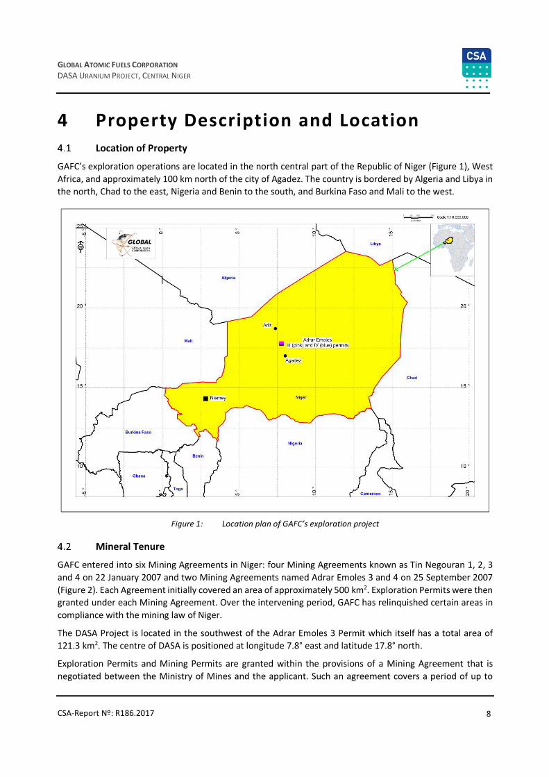
GAFC’s exploration operations are located in the north central part of the Republic of Niger (Figure 1), West
Africa, and approximately 100 km north of the city of Agadez. The country is bordered by Algeria and Libya in
the north, Chad to the east, Nigeria and Benin to the south, and Burkina Faso and Mali to the west.
Figure 1: Location plan of GAFC’s exploration project
Mineral Tenure
GAFC entered into six Mining Agreements in Niger: four Mining Agreements known as Tin Negouran 1, 2, 3
and 4 on 22 January 2007 and two Mining Agreements named Adrar Emoles 3 and 4 on 25 September 2007
(Figure 2). Each Agreement initially covered an area of approximately 500 km2. Exploration Permits were then granted under each Mining Agreement. Over the intervening period, GAFC has relinquished certain areas in
compliance with the mining law of Niger.
The DASA Project is located in the southwest of the Adrar Emoles 3 Permit which itself has a total area of
121.3 km2. The centre of DASA is positioned at longitude 7.8° east and latitude 17.8° north.
Exploration Permits and Mining Permits are granted within the provisions of a Mining Agreement that is
negotiated between the Ministry of Mines and the applicant. Such an agreement covers a period of up to

9
GLOBAL ATOMIC FUELS CORPORATION
DASA URANIUM PROJECT, CENTRAL NIGER
CSA-Report Nº: R186.2017
20 years, being the exploration period (three years plus two three-year renewals) and the first 10-year validity
period of a Mining Permit. The Mining Agreement is then renegotiated at each renewal of a Mining Permit.
The Mining Agreement can only be amended upon the mutual consent of both parties. The agreement must
be approved by a Decree of the Council of Ministers and is then signed by the parties and stipulates rights
and obligations of the parties during the validity period.
The Exploration Permit for Adrar Emoles 3 was granted on 8 February 2008 for the first three-year period on the perimeter defined to include approximately 488.7 km2. On 16 August 2010, the Exploration Permits for
all six Mining Agreements were extended by the Minister of Mines as a result of force majeure provisions.
The first three-year renewal of the Adrar Emoles 3 Exploration Permit was received on 17 January 2013,
concurrent with the required 50% reduction in area to approximately 243.7 km2. The second renewal was
granted on 29 January 2016, reducing the area to approximately 121.4 km2.
Figure 2: Adrar Emoles 3 and 4 Exploration Permits and location of the DASA deposit
Upon completion of a feasibility study, the holder of a Mining Agreement may apply for a Mining Permit. A
separate Niger Mining Company must be established to hold each Mine Permit. The Republic of Niger is
granted a 10% carried interest in the share capital of the Niger Mining Company at the time of its formation
and is entitled to its share of dividends that may arise.
The cumulative expenditures incurred to the date of formation of the Niger Mining Company and granting of
the Mining Permit are calculated; GAFC must negotiate with the Republic of Niger the amount that is to be
reimbursed to GAFC by the Niger Mining Company and the mechanisms for such reimbursement.

10
GLOBAL ATOMIC FUELS CORPORATION
DASA URANIUM PROJECT, CENTRAL NIGER
CSA-Report Nº: R186.2017
On the establishment of the Niger Mining Company, the Republic of Niger has the option to subscribe to an
additional 30% in the share capital of the Niger Mining Company. If the Republic of Niger fails to exercise the
option at that time, then it permanently loses the option.
If the Republic of Niger exercises some or all its option to the additional 30%, the Republic of Niger is obligated
to contribute its proportionate share of cash, financial commitments, capital contributions, shareholder
advances, bank and other loans for the duration of the Niger Mining Company.
A large-scale Mine Permit is valid for 10 years and may be renewed for five additional five-year periods. At
the time of renewal of a Mine Permit, the Mine Agreement is also renegotiated.
The area and geographic coordinates for the Adrar Emoles 3 Exploration Permit and the adjacent Adrar
Emoles 4 Exploration Permit are summarized in Table 2 below.
Table 2: Adrar Emoles 3 and Adrar Emoles 4 Exploration Permits
Adrar Emoles 3 Adrar Emoles 4
Tenement type: Exploration
Company: GAFC
Data granted: 29/01/2016
Validity: 3 years (second period)
Area: 121.2 km2
Tenement type: Exploration
Company: GAFC
Data granted: 29/01/2016
Validity: 3 years (second period)
Area: 122.4 km2
Point Longitude east Latitude north Point Longitude east Latitude north
A 7°40’00’’ 17°51’14’’ A 7°40’00’’ 17°45’30’’
B 7°46’28’’ 17°51’14’’ B 7°46’28’’ 17°45’30’’
C 7°46’28’’ 17°45’30’’ C 7°46’28’’ 17°39’43’’
D 7°40’00’’ 17°45’30’’ D 7°40’00’’ 17°39’43’’
To the extent known there are no other significant factors and risks than what is noted in this Report that
may affect access, title, or the right or ability to perform work on the property.

11
GLOBAL ATOMIC FUELS CORPORATION
DASA URANIUM PROJECT, CENTRAL NIGER
CSA-Report Nº: R186.2017
5 Accessibility, Climate, Local Resources, Infrastructure and Physiography
Accessibility
The project area is accessible by an all-weather road connecting Agadez (Niger’s second largest city) and the
final 10 km by unsealed sand piste. The mining town of Arlit is some 100 km north of the area of interest and Niamey (the capital of Niger) is some 1,000 km to the west. The main sealed road N25 (Figure 3) is also known
as the Routed Uranium (RTA) as it is here where all the yellow cake from the two AREVA uranium mines near
Arlit is transported by truck to the port of Cotonou in Benin, West Africa.
The road continues north from Arlit as a sand piste to the Algerian border and from there as a bitumen road
via Tamanrasset all the way to Algiers and the Mediterranean coast.
Figure 3: Road N25, just north of Agadez
There are two airports serving the general area: Agadez has a major airport, Mano Dayak, with a paved
3,000 m runway and recently significantly upgraded infrastructure. It is connected to the airport in Niamey,
some 720 km to the west, via charter flights or daily scheduled connections and at one time also handled
international tourist flights from Europe.
Arlit also has an airport with an unpaved much shorter runway, however nearly all flights operating from here
are charters for AREVA’s mining operations.
The GAFC exploration “Daji” camp (Figure 4) is located some 100 km north of Agadez and 10 km straight east
of the N25 highway, easily accessible via a sand piste. Its coordinates are 17°47’54’’ N and 7°43’33’’ E.

12
GLOBAL ATOMIC FUELS CORPORATION
DASA URANIUM PROJECT, CENTRAL NIGER
CSA-Report Nº: R186.2017
Figure 4: GAFC’s Dajy exploration camp
With a few exceptions of rough, rocky terrain, the whole project area is easily traversed by all-terrain vehicles
or four-wheel drive cars.
Climate
The region is characterized by an arid intermediate climate of the Sahalian desert type with two distinct main
seasons: the dry season between October and May and the wet season from June to September.
The temperatures can vary between 0°C at night in January to more than 55°C in May or June during the day.
The mean annual precipitation is less than 200 mm and up to 90% of it occurs during the wet season. The
rainy season provides sufficient precipitation to allow local basic agricultural activities. Flash floods are
frequent inside alluvial dry river beds originating in the Air Mountains and can quickly turn into torrential
streams making local roads temporarily impassable. Much of the sparse vegetation grows around the river
beds.
Given the very arid environment and limited rainfall, the site is accessible year-round for exploration activities.
However, given the extreme summer time temperatures, the height of summer (May to July) should be
avoided.
Physiography
The Exploration Permits are located between the western foreland of the Air Mountains and the N25 highway
connecting Agadez to Arlit on the eastern edge of the Tim Mersoi Basin. The terrain is generally flat (Figure 5),
monotonous sandy peneplain with an average elevation of some 500 m above sea level (ASL) with elevations
decreasing to the west. The highest elevation is in the Azouza hills, 553 m ASL, whereas the Air Mountains,
located some 30 km to the east may reach over 1,800 m ASL.

13
GLOBAL ATOMIC FUELS CORPORATION
DASA URANIUM PROJECT, CENTRAL NIGER
CSA-Report Nº: R186.2017
Figure 5: Typical terrain at DASA Project area
Local Resources and Infrastructure
The project is located in the department of Agadez which comprises 52% of the surface area of Niger, but has
only 322,000 inhabitants with a population density of 0.2/km2.
The GAFC project area is traversed by a 132 KV powerline connecting the Sonichar power plant – located
some 40 km south of the project near the small city of Tchirezrine – with the two uranium mines near Arlit,
120 km to the north. The power plant runs two 16 MW generators and is fed by coal which was discovered
during the uranium exploration phase in the early 1970s.
Sonichar also supplies electricity to the city of Agadez and has considerable excess capacity for any industrial
development in the area.
There are no permanent surface water sources available but several underground aquifers exist at depths
between 300 m and 500 m.
A large pool of mostly unskilled labour is available on short notice within the immediate project area or from
Agadez and Arlit. The AREVA (ex Cogema) uranium operations have trained a local labour force over the years
and able workers can be expected to be available. This includes technical personnel from supervisory levels
upwards.
The labour code and the organization of labour are very much based upon the French system.
Mining equipment and most supplies need to be imported from outside Niger. Warehousing facilities exist to
some extent in Agadez or Arlit.
Niger has a long history of resource extraction and mining and exploration services are available on a local
level reaching from drilling companies to environmental consultants and support services.

14
GLOBAL ATOMIC FUELS CORPORATION
DASA URANIUM PROJECT, CENTRAL NIGER
CSA-Report Nº: R186.2017
6 History
Introduction
Uranium exploration did not commence in Niger until the early 1950s, following up on indications from spotty
surface mineralization. The exploration for uranium occurred over time in three phases dictated by the
economics of the mineral at various times.
This following section is based on information sourced from the following reports: Périmètre In Adrar (1977),
Rapport des activités de la champagne de prospection d’uranium, Association Onarem PNC (1983), Projet
Sekiret, Programme des Travaux de la 3eme Campagne (1983–1984), Association Onarem PNC, Annual
technical report (1984), Projet Sekiret, Programme des Travaux de la 4eme Campagne (1984–1985),
Association Onarem PNC (1985), Projet Sekiret, Programme des Travaux de la 5eme Campagne (1985–1986),
Association Onarem PNC (1986).
Regional Exploration by the French Nuclear Energy Commission (1957–1981)
Systematic uranium exploration in the area started in 1959 after the first uranium mineralization was noted
during geological reconnaissance missions in the Air Maintains in 1956 (J.R. Leconte mission) and in 1957/58
near Azelik just west of the GAFC property during an exploration program for copper in the Teguida n’Adrar-
Assaouas region.
The French Nuclear Energy Commission (Commissariat a l’Energie Atomique, “CEA”) was responsible for all
the work. From 1957–1967, an intensive geological exploration program was implemented, which resulted in
the discovery of the uranium deposits of Azelik (1960), Madaouela (1964), and finally Arlit-Akouta (1966–
1967).
Airborne radiometric and magnetic surveys located a large number of surface anomalies which were quickly
followed up on the ground. The CEA later merged into Cogema (now called AREVA) and substantial
exploration programs were carried out over the years. The Exploration Permit over the areas presently held
by GAFC was called “In Adrar”.
In the late 1960s, Cogema completed wide-spaced drilling (several kilometres apart) to test the stratigraphy
of the area and to investigate how closely the geology resembled that of the Arlit area further north where
uranium mineralization was already known since the mid 1960s.
In addition to the drilling, other exploration techniques such as geological mapping, rock and water well
sampling, ground radiometric surveys and airborne surveys such as magnetic, electromagnetic and
radiometric were employed.
A 250 m-line spaced airborne radiometric survey delineated a large number of anomalies which were
confirmed on the ground and consequently drilled. At this stage, the drilling rather aimed at identifying the
stratigraphy than mineralization. Much of this drilling was rotary, “wild cat” spaced at several kilometres. This
was reduced to 800 m and 400 m in more encouraging areas. Core drilling was used to confirm the geology
and lithology as needed.
The first holes were completed in 1960 and continued until 1972 within the “In Adrar” concession including
the Dajy area. A total of 652 holes were completed all over the concession, of which 12 were in the closer
ranges of Dajy. No holes were drilled within the actual DASA area.
The drilling confirmed that the area was underlain by stratigraphy closely resembling that of the Arlit region.

15
GLOBAL ATOMIC FUELS CORPORATION
DASA URANIUM PROJECT, CENTRAL NIGER
CSA-Report Nº: R186.2017
All holes were probed by radiometric and electric methods using Cogema’s own logging systems.
Significant radiometric anomalies were discovered within the Adrar Emoles 3 Permit in strata younger than
the Upper Jurassic Imouraren world class uranium deposit, located only some 40 km northwest of DASA.
Regional Exploration by PNC and ONAREM (1981–1990)
In 1981, Cogema dropped major parts of their landholdings due to the suppressed uranium market at that
time. A joint venture between Power Reactor and Nuclear Fuel Development Corporation (PNC) based in Japan and ONAREM (Niger National Geological Survey) acquired a large exploration permit called Sekiret
which covered an area of some 4,200 km2. PNC conducted stratigraphic drilling on 800 x 800 m and 400 x
400 m centres.
In 1982, 4,686 m were drilled on several kilometre-wide spaced grids, exploring a number of ground
anomalies. A much larger program was completed in 1983, 36 holes totalling 11,000 m, as a combination of
rotary and cored drilling. Drillhole spacing was 2.5 x 2.5 km over western and eastern sections of the property.
All drillholes were probed for natural gamma, resistivity sonic and caliper using Japanese made equipment.
In 1984, encouraging results were noted in 13 drillholes (6,266 m) in the Dajy area, 13 core holes (1,848 m) in
the Sekiret area and five drillholes (2,672 m) near the Arlit fault in the west.
In 1985/86, 27 drillholes (10,702 m) were completed, of which 7,808 m were core and 2,894 m were rotary.
Some of the holes were over the northern sector while others were placed over Dajy and Isakanan. Additional
drilling was done in 1987 (7,672 m) seven holes with 2,139 m in 1988 and 11 holes in 1988 totalling 3,505 m,
and finally 12 drillholes or 3,466 m in 1990.
PNC’s work confirmed that uranium was present in the Tarat, Madaouela and Guezouman Formations and in
a surface anomaly at DASA in the sandstones of the Tchirezrine 2 Formation.
The drilling was successful in expanding the Dajy prospect and discovering the Isakanan prospect. The joint
venture terminated in 1988.
From 1990 to 2007, the Adrar Emoles 3 and 4 areas remained unexplored and no known exploration activity
can be reported.
Exploration Activity from 2007 Onwards
In September 2007, the Adrar Emoles 3 and 4 blocks were granted to GAFC totalling about 1,000 km2, located
some 50 km east of AREVA’s proposed large Imouraren open pit. Mineralization was known to exist within
the lower Carboniferous Guezouman and Tarat sediments and the lower Cretaceous Tchirezrine 2 sandstone.
The Adrar Emoles 3 block includes the Dajy prospect where uranium mineralization was known to occur within
a 10 km-long x 2 km-wide zone. Dajy is situated along a northwest-southeast trending major lineament, the
Azouza fault along which the Azelik deposit (37 Mlb) is situated, owned by CNNC, a Chinese government
agency.
The Tchirezrine 2 sandstone is outcropping in the Adrar Emoles 3 block over wide areas. This strata also hosts
the very large (>300 Mlb AREVA-owned) Imouraren deposit.
An historic estimate of tonnes and grade by GEOEX in 2009 yielded 27.9 Mt of ore at a grade of 821 ppm
eU3O8 or 50.5 Mlb eU3O8 for the Adrar Emoles concession (Isakanan area and Dajy).
In 2011, GAFC announced new uranium discoveries at the Adrar Emoles 3 concession on the current known
DASA (Dajy Surface Anomaly) area – named to differ from the known Dajy prospect. The discoveries are

16
GLOBAL ATOMIC FUELS CORPORATION
DASA URANIUM PROJECT, CENTRAL NIGER
CSA-Report Nº: R186.2017
located along the Azouza fault and hosted in the Tchirozerine 2 lower Cretaceous sandstones which also hosts
the proposed AREVA Imouraren >300 Mln open pit deposit. Imouraren is situated less than 50 km away. The
mineralization is contained in a horst and graben environment with up thrust blocks. Intersections at Dasa 1
were 0.26% U3O8 over 8.8 m; Dasa 2 of 0.11% U3O8 over 8.6 m; and Dasa 3 of 0.11% U3O8 over 76 m.
Additional exploration work located uranium grades from blowouts on surface as high as 30% U3O8 within the
Tchirezrine 2 sandstone.
Later drilling confirmed that high grade mineralization exists below the planned open pit with reported grades
in hole ASDH 307 of 0.35% eU3O8 over 30 m and hole ASDH 248 at 0.21% eU3O8 over 25 m.
In June 2012, the Dajy exploration camp was opened, allowing easier access to the whole concession area
and the drill sites.
A Qualified Person has not done sufficient work to classify the historical estimate as current Mineral
Resources or Mineral Reserves. The issuer is not treating the historical estimate as current Mineral Resources
or Mineral Reserves.
Previous Mineral Resource Estimation
Mineral Resource estimation for the DASA Project has previously been done by SRK Consulting (Canada) in
13 September 2013 (Mineral Resource Evaluation, 2013) (Table 3).
Table 3: Mineral Resource Statement*, DASA Uranium Project, Republic of Niger, SRK Consulting (Canada) Inc., 20
September 2013 Category
Category ‘000 tonnes eU3O8 ppm eU3O8 Mlb
Inferred (open pit)** 4,713 579 6.01
Inferred (underground)*** 19,396 1,797 76.84
Inferred – Total 24,109 1,559 82.86
* All figures rounded to reflect the relative accuracy of the estimates. Mineral Resources are not Mineral Reserves and have not demonstrated
economic viability.
** Open pit Mineral Resources reported at a cut-off grade of 250 ppm of eU3O8 per tonne assuming: metal price of US$70/lb of U3O8, mining cost of
US$5/tonne, processing and G&A cost of US$5/tonne, processing cost of US$24/tonne, process recovery of 90%, exchange rate of C$1.00 equal
US$1.00, a mining rate of 10,000 tonnes/day and a pit slope angle of 45°.
*** Underground Mineral Resources reported at a cut-off grade of 600 ppm of eU3O8 per tonne assuming: metal price of US$70/lb of U3O8, mining cost
of US$71/tonne, processing and G&A cost of US$5/tonne, processing cost of US$24/tonne, process recovery of 95%, exchange rate of C$1.00 equal
US$1.00, and a mining rate of 5,000 tonnes/day.
A Qualified Person has not done sufficient work to classify the historical estimate as current Mineral
Resources or Mineral Reserves. The issuer is not treating the historical estimate as current Mineral Resources
or Mineral Reserves.
Production from the Property
No production from the property is known.

17
GLOBAL ATOMIC FUELS CORPORATION
DASA URANIUM PROJECT, CENTRAL NIGER
CSA-Report Nº: R186.2017
7 Geological Setting and Mineralisation
Introduction
This section is prepared based on the following reports: Activation Lab. (2007), Perimetre Tin Adradar; Dossier
Technique (1977), Jean Martin von Siebenthal (2013), Cazoulat (1985), Gauthier (1972), Gauthier (1974),
Gerbaud (2006), https://www.uni-hohenheim.de/atlas308/startpages/page2/french/content_fr/conframe_fr.htm,
Guiraud (1981), Greigert and Pougnet (1967), Hirlemann and Robert (1977), Hirlemann and Faure (1978),
Hirlemann and Robert (1980), Joulia (1957), Joulia (1959), Joulia (1963), Joulia and Obellianne, (1976), Konaté et al. (2007), Lang et al. (1991), Molebale (2012), Sempéré (1981), Valsardieu (1971), Wright (1993), Wright
(2010), Wright (2012), Yahaya (1992), Yahaya and Lang (2000).
Regional Geology
The GAFC property is located in north-eastern Niger inside the Tim Mersoi sedimentary basin (Figure 6). The
basin covers an area of some 114,000 km2 and is part of the much larger Iullemeden Basin (Palaeozoic-
Tertiary) that stretches into Mali, Algeria, Benin and Nigeria.
In the north and east, the Iullemeden Basin (including Tim Mersoi Bassin) is bounded by the Hoggar Massif in
Algeria and the Air Massif in Niger forming part of the Central Saharan Massif (Figure 7). The basin gets deeper
to the south and the west. During the early Palaeozoic, continental sediments were deposited into an open
gulf to the south of the Central Saharan Massif. In the Mesozoic and Tertiary, marine transgressions invaded
from time to time diminishing in thickness to the south and passing laterally into continental series. Uplifts
commenced in the mid Eocene, filling the basin with fluvial and lacustrine sediments.
All uranium deposits currently known in Niger are located within the Tim Mersoi Basin in several areas
(Figure 6 and Figure 8):
• Near the city of Arlit, in the two AREVA mines of SOMAIR – open pit (discovered in 1967) and COMINAK
Akouta – underground mine (discovered in 1974), with historical production of over 110,000 tons of
uranium. Production in 2015 was some 4,116 tonnes of uranium.
• In the Teguida area, Azelik – open pit (SOMINA/CNNC producing since 2011 but presently closed).
• At Imouraren (Imouraren SA/AREVA, construction starting in 2009 and production was originally planned
to commence in 2015), projected to be the largest open pit uranium mine in the world. This project is
currently on standby.

18
GLOBAL ATOMIC FUELS CORPORATION
DASA URANIUM PROJECT, CENTRAL NIGER
CSA-Report Nº: R186.2017
Figure 6: Regional geology map
Source: After F. Julia, printed by BRGM in 1963 at 1:500,000

19
GLOBAL ATOMIC FUELS CORPORATION
DASA URANIUM PROJECT, CENTRAL NIGER
CSA-Report Nº: R186.2017
Figure 7: Major structures in the Tim Mersoï Basin, shaping it in a succession of ridges and basins
To the east, the basin rests unconformably on the crystalline basement of the Air Massif, a Precambrian
metamorphic terrain intruded by post Mesozoic felsic and mafic intrusives and in the north and northwest on
the basement rocks of the Hoggar in Algeria. The Air Massif extends north into Algeria where it becomes the
Ouzzalian Craton also of Precambrian age. The Air Massif represents the source for all the clastic sediments
that over time have filled the Tim Mersoi Basin and is probably also the source of at least some of the uranium
found in the basins clastic sediments.
The sediments of the basin reach in age from Paleozoic to Cenozoic (Figure 8) and up to 1,500 m in total
thickness deposited on a relatively stable platform.
20
GLOBAL ATOMIC FUELS CORPORATION
DASA URANIUM PROJECT, CENTRAL NIGER
CSA-Report Nº: R186.2017
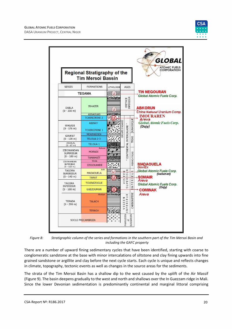
Figure 8: Stratigraphic column of the series and formations in the southern part of the Tim Mersoi Basin and
including the GAFC property
There are a number of upward fining sedimentary cycles that have been identified, starting with coarse to
conglomeratic sandstone at the base with minor intercalations of siltstone and clay fining upwards into fine
grained sandstone or argillite and clay before the next cycle starts. Each cycle is unique and reflects changes
in climate, topography, tectonic events as well as changes in the source areas for the sediments.
The strata of the Tim Mersoi Basin has a shallow dip to the west caused by the uplift of the Air Massif
(Figure 9). The basin deepens gradually to the west and north and shallows over the In Guezzam ridge in Mali.
Since the lower Devonian sedimentation is predominantly continental and marginal littoral comprising

21
GLOBAL ATOMIC FUELS CORPORATION
DASA URANIUM PROJECT, CENTRAL NIGER
CSA-Report Nº: R186.2017
conglomerate, sandstone, siltstone and shale, deposited by large meandering rivers in fluvial and deltaic
settings into a slowly subsiding foreland. Further to the west a more marine environment existed (Joulia et
al., 1959).
Figure 9: Northwest-southeast profile in the Arlit area, see A-B cut on above
Source: Modified Cominak document, 1989; Gerbaud, 2006
The general direction of transport is assumed to have been from the east to the west and in the area of
interest a more northeast to the southwest direction of transport would have prevailed.
In general, it can be said that the sedimentary strata become younger from north to south, possibly a
combination of uplift of the Air Massif and erosion and transport directions.
Obelliane et al. (1971) have identified three distinct sedimentary areas within the Tim Mersoi Basin with the
main depositional areas moving slowly north to south over time:
• A Lower Carboniferous basin (the Tin Seririne synclinorium) of fluvial-deltaic marine and sediments. This
strata is rich in organic matter and silicified trees are common in certain areas of the basin.
• A smaller Permo-Triassic basin with intercalations of volcano sedimentary and fluvial sediments.
• A lower Cretaceous basin with lacustrine deposits overlain by fluvial-deltaic sediments.
Structural Setting
The Tim Mersoi Basin occurs as a regional scale syncline with a fold axis trending north-south, affected by a
combination of brittle faults, mixed flexure-faults, or low amplitude folds or flexures.
The Tin Seririne synclonorium was formed during the Pan African Orogenic event from 550 M onwards and
forms the northern part of the Tim Mersoi Basin with sedimentation that began during the Cambrian (Joulia
et al., 1959).
The structural development of the Tim Mersoi Basin commences at the end of the Pan African Orogen event
(1000 MA). The basin develops by north-south and east-west compression with northwest to west-northwest
sinistral shears caused by anti-clockwise rotation in the northeast of the basin. With the widening and

22
GLOBAL ATOMIC FUELS CORPORATION
DASA URANIUM PROJECT, CENTRAL NIGER
CSA-Report Nº: R186.2017
deepening of the basin, its centre and the north-eastern edges see the development of sinistral shear zones
and conjugate structures trending northwest-southeast and northeast-southwest. The intersections between
these structures contain rotational deformation causing dome and basin structures.
Major movements are related to north-south zones which strike parallel to the eastern and the western edges
of the Air Massif. The compressional sinistral strike slip movements have caused three main structural
directions which are north-south; 40-80º; and 90-135º. Where these structures intersect, ideal pathways for circulating uranium-bearing fluids to form deposits are created.
7.3.1 South Fault System and N30°E Associated Structures
The fold-fault of In Azaoua-Arlit comprises a major regional-wide north-south fault system. This family of
structures is related to ancient late-Panafrican transform events. Its frequent reactivation, depending on the
epochs, translates into faults, flexures and flexure-faults in the sedimentary cover.
The N30° family of structures are the most evident on surface in the Tim Mersoï Basin. They appear in the Aïr
basement in the east and stop at the In Azaoua-Arlit lineament in the west, where they are truncated. They
are linked to the In Azaoua-Arlit history (Sempéré, 1981).
In the sedimentary cover, the deformation is characterized by flexures (Gauthier, 1972; Hirlemann et Robert,
1977, 1980), creating in some instances a substantial vertical displacement in the order of 100–200 m.
According to Hirlemann and Robert (1977, 1980), these flexures are linked with sinistral reverse-strike-slip
faults activity of the basement structures in a compressive regime.
According to Guiraud et al. (1981), the compressive phase associated with the formation of the N30° flexures
is of Upper Cretaceous age, with a shortening direction of N140°.
7.3.2 N130-N140°E and N70-N80°E Conjugate Fault System
A second grouping of faults occurs with orientations of N130–N140°E and N70–N80°. These brittle structures
are the most important family in the Aïr Massif. They are of late-Panafrican origin according to Greigert and
Pougnet (1967).
The N70–N80°E faults are conjugate to the N130–N140°E directions. They are mainly present in the southern
half of the Tim Mersoï Basin. During the Carboniferous, these structures controlled the sedimentation in the
basin (Wright et al., 1993). These faults played a major structural role in the regional context of the basin, by
localizing large scale dextrous strike-slip faults (Gauthier, 1972; Hirlemann and Robert, 1980).
7.3.3 Fold-like Structures
Fold-like structures are common within the sediments. According to geological drilling data, the thickness and
dip variations in some strata from west to east are linked with synsedimentary tectonic activity (Gerbaud,
2006).
Two families of fold-like structures are distinguished:
• Anticlines/synclines, with fold axes roughly parallel to the N30°E structures
• Closed structures (domes), which generally appear at the intersection of the N30°E structures and N70–-
N80°E.
In the south, near the Adrar Emoles 3 and 4 permits, the north-south, east-west and sinistral shears combine
to develop folding, the most obvious being a syncline, in which the Asouza structure is an integral part. The

23
GLOBAL ATOMIC FUELS CORPORATION
DASA URANIUM PROJECT, CENTRAL NIGER
CSA-Report Nº: R186.2017
stratigraphy is also folded on approximately layer parallel axis which gives wider exposures and repetition of
units. The layers are thickened by layer parallel shortening and on-echelon structures develop (Wright, 2010,
2012).
Property Geology
The rocks present within the GAFC property range in age from Cambrian to lower Cretaceous age (Figure 10).
The schematic geological map is shown in Figure 6 and on the schematic cross-section in Figure 12 .
They are mostly clastic sediments with minor carbonates. They originated from the Air Massif which has been
continuously eroded since at least the Mesozoic. The sediments were laid down in a continental setting and
are generally comprised of fluvial and deltaic settings. In this environment, large shallow rivers meander
across flat topography and create complex flow patterns where the coarse-grained sands and gravel are
concentrated in the actual channels with the highest flow energies while low energy flow regimes on the
floodplains and tidal areas create silt and mudstone-type sediments.

24
GLOBAL ATOMIC FUELS CORPORATION
DASA URANIUM PROJECT, CENTRAL NIGER
CSA-Report Nº: R186.2017
Figure 10: Stratigraphic column of the DASA project area
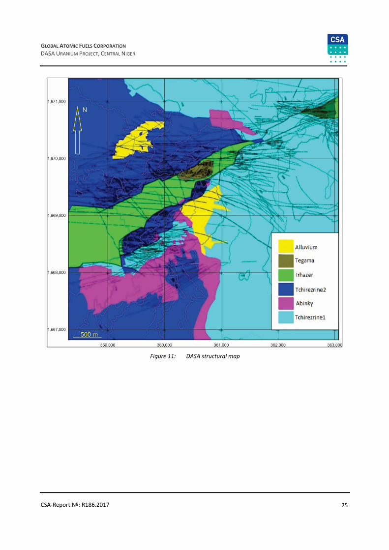
25
GLOBAL ATOMIC FUELS CORPORATION
DASA URANIUM PROJECT, CENTRAL NIGER
CSA-Report Nº: R186.2017
Figure 11: DASA structural map

26
GLOBAL ATOMIC FUELS CORPORATION
DASA URANIUM PROJECT, CENTRAL NIGER
CSA-Report Nº: R186.2017
Figure 12: DASA schematic geological section
The points below provide a brief summary of the lithologies of the project recorded in drilling, surface
mapping and geophysical surveys of the project areas:
• Precambrian:
o Metamorphic Basement is exposed in the Air Mountains to the east. Some of GAFC’s drillholes inside
the DASA graben terminated in altered and in fresh granite. Its position within the basement suites is
unknown at this time.
• Cambro-Ordovician undifferentiated:
o Cambrian to Devonian rocks exist in this part of the Tim Mersoi Basin, however they have not been
positively identified yet by GAFC’s work. A major discordance near the Air Massifs western boundary
separates the basement from conglomerates and tillites of the Timesgueur Formation followed by In
Azawa sandstone followed by another major discordance.
• Upper Ordovician:
o The upper Ordovician consists of fine-grained sandstones with quartz pebbles and calcite.
• Silurian:
o The Silurian consists of graptolite schists.
• Devonian:
o The Lower Devonian starts with an unconformity followed by conglomerate with pebbles of schists
and basalt, Idekel sandstone with silicified wood and is overlain by Middle Devonian Touaret
sandstone, fossiliferous beds and the Akara schist. The Devonian is completed by Upper Devonian
Amesgueuer sandstone.

27
GLOBAL ATOMIC FUELS CORPORATION
DASA URANIUM PROJECT, CENTRAL NIGER
CSA-Report Nº: R186.2017
• Carboniferous:
o Carboniferous formations are major host rocks for uranium mineralization particularly in the northern
part of the basin. The Carboniferous–Lower Visean begins with fossiliferous marine argillites which are overlain by the clastic terrestrial Terada Series which may reach thicknesses of up to 290 m. The
Terada itself is made up of the Teragh Formation consisting of coarse-grained sandstones, which can
contain coal beds, and is overlain by the siltstones and sandstones of the Aoulingen Formation. This
passes laterally to the north into the marine Talach argillites.
o The Carboniferous–Upper Visean continues with the important fluvio-deltaic Tagora Series which
hosts uranium in the wider Arlit region of the basin. The Tagora is made up of two cycles: The lower
Tagora up to 180 m thick, starting with the conglomerates of the Teleflak and continuing into the
sandstones making up the Guezouman Formation. This is a major host for uranium mineralization in
the Akouta area (Cominak underground mine-AREVA) and which is overlain by the siltstones of the
Lower Tchinezogue Formation which is a mega-sequence comprised of the whitish sandstones of the
Middle and Upper Tchinezogue.
o The second cycle of the Tagora (0–140 m thickness) often is marked with a thin layer of conglomerate
overlain by the sandstone of the Tarat Formation with intercalations of siltstone and argillite in an
upward fining sequence. The uranium at Arlit (Somair open pit mines-AREVA) is hosted in this second
cycle. The top of the Carboniferous is completed by sandstones and siltstones of the Madaouela
Formation (GOVIEX Madaouela project).
o The Carboniferous in the whole basin is characterized by reducing conditions displayed in
predominantly greyish colours, pyrite and organic matter providing ideal conditions for the
precipitation of uranium.
• Permian:
o During the Permian, a major change in climatic conditions occurred and this is reflected in the rocks
of that period. The Permian sediments are generally characterized by an abundance of arkosic
sandstones containing significant volcanic debris. Reddish colours and abundant calcite are dominant
for the Permian strata indicating oxidizing conditions. The sedimentation occurred mostly in
interwoven channels with frequent and abrupt facies changes. Within the project area, the thickness
of the Permian strata can vary considerably and reach a thickness of some 300 m.
o The Lower Izegouandane Series begins with coarse grained sandstones containing pebbles of rhyolite
and quartzite. It is overlain by 5–10 m of a red claystone (equivalent to the Teja Formation) and
followed by the sandstones of the Tamamait Formation. Further up in the sequence the red siltstone
of the Moradi Formation is common. The latter two Formations belong to the Upper Izegouande
Series.
• Triassic:
o Initially, the Triassic shows a continuation of the Permian conditions beginning with the
conglomerates of Anou Melie that contain many pebbles shaped by aeolian actions (windkanter).
o These are covered by fluvio-deltaic sandstones belonging to the Teloua 1 Formation. This package
may reach 60 m in thickness and belongs to the Aguelal Series. In some areas, the Teloua 1 displays
as reworked sediment with well sorted and rounded quartz pebbles reflecting the local paleo
topography.
o The following sediments of the Goufat Series contain masses of volcanic debris (origin volcanic tuffs?)
and are called the Teloua 2 (some 70 m thick). The Teloua 2 appears as distinct poorly sorted sand
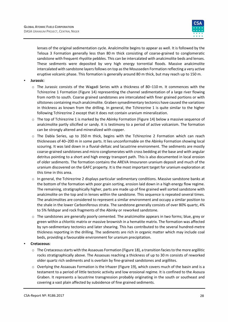
28
GLOBAL ATOMIC FUELS CORPORATION
DASA URANIUM PROJECT, CENTRAL NIGER
CSA-Report Nº: R186.2017
lenses of the original sedimentation cycle. Analcimolite begins to appear as well. It is followed by the
Teloua 3 Formation generally less than 80 m thick consisting of coarse-grained to conglomeratic
sandstone with frequent rhyolite pebbles. This can be intercalated with analcimolite beds and lenses.
These sediments were deposited by very high energy torrential floods. Massive analcimolite
intercalated with sandstone layers follows on top as the Mousseden Formation reflecting a very active
eruptive volcanic phase. This formation is generally around 80 m thick, but may reach up to 150 m.
• Jurassic:
o The Jurassic consists of the Wagadi Series with a thickness of 80–110 m. It commences with the
Tchirezrine 1 Formation (Figure 14) representing the channel sedimentation of a large river flowing
from north to south. Coarse grained sandstones are intercalated with finer grained portions or with
siltstones containing much analcimolite. Graben synsedimentary tectonics have caused the variations
in thickness as known from the drilling. In general, the Tchirezrine 1 is quite similar to the higher
following Tchirezrine 2 except that it does not contain uranium mineralization.
o The top of Tchirezrine 1 is marked by the Abinky Formation (Figure 14) below a massive sequence of
analcimolite partly silicified or sandy. It is testimony to a period of active volcanism. The formation
can be strongly altered and mineralized with copper.
o The Dabla Series, up to 350 m thick, begins with the Tchirezrine 2 Formation which can reach
thicknesses of 40–200 m in some parts. It lies unconformable on the Abinky Formation showing local
scouring. It was laid down in a fluvial-deltaic and lacustrine environment. The sediments are mostly
coarse-grained sandstones and micro conglomerates with cross bedding at the base and with angular
detritus pointing to a short and high energy transport path. This is also documented in local erosion
of older sediments. The formation contains the AREVA Imouraren uranium deposit and much of the
uranium discovered on the GAFC property. It is the most important target for uranium exploration at
this time in this area.
o In general, the Tchirezrine 2 displays particular sedimentary conditions. Massive sandstone banks at
the bottom of the formation with poor grain sorting, erosion laid down in a high energy flow regime.
The remaining, stratigraphically higher, parts are made up of fine grained well sorted sandstone with
analcimolite on the top and in lenses within the sandstone. This sequence is repeated several times.
The analcimolites are considered to represent a similar environment and occupy a similar position to
the shale in the lower Carboniferous strata. The sandstone generally consists of over 80% quartz, 4%
to 5% feldspar and rock fragments of the Abinky or reworked sandstone.
o The sandstones are generally poorly cemented. The analcimolite appears in two forms; blue, grey or
green within a chloritic matrix or massive brownish in a hematite matrix. The formation was affected
by syn-sedimentary tectonics and later shearing. This has contributed to the several hundred-metre
thickness reporting in the drilling. The sediments are rich in organic matter which may include coal
beds, providing a favourable environment for uranium precipitation.
• Cretaceous:
o The Cretaceous starts with the Assaouas Formation (Figure 18), a transition facies to the more argillitic
rocks stratigraphically above. The Assaouas reaching a thickness of up to 30 m consists of reworked
older quartz rich sediments and is overlain by fine-grained sandstones and argillites.
o Overlying the Assaouas Formation is the Irhazer (Figure 19), which covers much of the basin and is a
testament to a period of little tectonic activity and low erosional regime. It is confined to the Asouza
Graben. It represents a lacustrine transgression probably originating in the south or southeast and
covering a vast plain affected by subsidence of fine grained sediments.

29
GLOBAL ATOMIC FUELS CORPORATION
DASA URANIUM PROJECT, CENTRAL NIGER
CSA-Report Nº: R186.2017
o Uranium exists here and is being mined at the Abkorun property by China National Uranium
Corporation just to the west of the GAFC property.
o The stratigraphic column of the project area culminates in the sandstones of the Tegama Series which lie with a marked unconformity on the Irhazer sediments. Tegama sandstone is present in two bigger
hills inside the Asouza Graben. The lithology here are sandstones which are cross-bedded and coarse
to micro conglomeratic. The formation displays heavy quartz veining related to the faults and
fractures bisecting it (Figure 20 and Figure 21).
Figure 13: Cross-beds in coarse grained to micro-conglomeratic sandstone, Tchirezrine 1 Formation

30
GLOBAL ATOMIC FUELS CORPORATION
DASA URANIUM PROJECT, CENTRAL NIGER
CSA-Report Nº: R186.2017
Figure 14: Massive analcimolite, Abinky Formation
Figure 15: Tchirezrine 1 sandstone covered in the foreground by analcimolite of the Abinky Formation

31
GLOBAL ATOMIC FUELS CORPORATION
DASA URANIUM PROJECT, CENTRAL NIGER
CSA-Report Nº: R186.2017
Figure 16: Cross-bed figures in the Tchirezrine 2, northern outcrops at DASA
Figure 17: North-south structures in sandstone, Tchirezrine 2 unit, eastern outcrops at DASA

32
GLOBAL ATOMIC FUELS CORPORATION
DASA URANIUM PROJECT, CENTRAL NIGER
CSA-Report Nº: R186.2017
Figure 18: Siltstone outcrop, Assaouas Formation, southern outcrops
Figure 19: Irhazer Formation, limestone strata within argilite, crosscut by east-west transform faults , north-eastern
outcrops

33
GLOBAL ATOMIC FUELS CORPORATION
DASA URANIUM PROJECT, CENTRAL NIGER
CSA-Report Nº: R186.2017
Figure 20: Heavily quartz veined Tegama sandstone; mount inside the Assouza Graben
Figure 21: Conjugate fracture veined in quartz in coarse cross-bed Tegama sandstone
34
GLOBAL ATOMIC FUELS CORPORATION
DASA URANIUM PROJECT, CENTRAL NIGER
CSA-Report Nº: R186.2017
Structural Geology of the Property
Structural control is important in the formation of most uranium deposits and the DASA area is no exception.
The arid climate has prepared and well preserved structural features many of which can be observed at
surface.
The DASA site corresponds to a major structural intersection of the Adrar-Emoles flexure and the Asouza fault
which resulted in the doming and creation of the Asouza Graben (Siebenthal, 2013). These are features that
characterize other major uranium deposits in the Tim Mersoi Basin as well.
• Adrar Emoles flexure:
o The Adrar Emoles flexure-fault, one of the major northeast-southwest structures, intersects the
Asouza fault at DASA. This intersection formed a dome, the opening of which created the Asouza
Graben (Figure 22) moving the Cretaceous formations to the same topographic elevation as the
surrounding Jurassic sandstones.
• Asouza fault:
o Major northeast-southwest vertical faults are associated with the Asouza Graben, and characterized
by significant vertical displacement of several hundred meters.
o The creation of the graben preserved the Tegama and Irhazer Formations at depth, elsewhere found
much farther to the west in the deeper areas of the Tim Mersoin Basin. It also preserved the rocks of
the Tchirezrine 2 formation which are much eroded on the sides of the graben.
o This vertical displacement has had a major impact in the continuation of potential host rock geometry,
and has also provided feeder faults and mineralization traps for mineralising fluids as evidenced by
veining within the sandstones.
• North-northwest to south-southeast faults and folds:
o Of key interest are the north-northwest to south-southeast faults observed northwest of the graben.
They cut the sandstone formations of the Tchirezrine 2 unit, inducing vertical displacement, with
evidence of fluid circulation, enacting localized alteration and copper mineralization in analcimolite
formation of the Tchirezrine 2 unit.
• Shearing fractures and veins:
o Shearing fractures and veins appear in the limestone, particularly of Jurassic age, near the major faults
that have a strike-slip component similar to the Asouza and its branches, and the east-west strike-slip
faults.
• East-west strike-slip faults:
o Within the upper, northern termination of the Asouza Graben and elevated from the surrounding
plain a limestone outcrop of the Irhazer Formation displays strike-slip faults evidence. A closer
examination of the satellite imagery reveals a set of roughly east-west oriented structures on both
sides of the graben. These are most likely conjugate to the Asouza fault.

35
GLOBAL ATOMIC FUELS CORPORATION
DASA URANIUM PROJECT, CENTRAL NIGER
CSA-Report Nº: R186.2017
Figure 22: Looking southwest, Asouza Graben: Cretaceous Tegama sandstones in the foreground, resting on several
hundred meters of Cretaceous Irhazer Formation to the left with Jurassic Tchirezrine 2 sandstone in the
background. Displacement is in the order of several hundred metres
Uranium Mineralization
Uranium mineralization in Niger is located in sediments of the Tim Mersoi Basin and occurs in most of the
thicker sandstone units described earlier, however not always in economic concentrations and tonnage.
Uranium is known in the Carboniferous Terada series, in the Carboniferous Tarat and Guezouman Formations
(Arlit mines), in the Permian Izegouande, the Jurassic Tchirezrine 2 Formation (Imouraren, DASA, Azelik) and
the Cretaceous Dabla Series as well as in the Tegama Series.
There are three areas in eastern Niger where uranium is presently being mined or could be mined in the near
future:
• Arlit-Akokan (Akouta) hosting the Somair open pit and the Cominak underground mines (both mainly
owned by AREVA) which have produced so far over 110,000 tonnes of uranium since the early 1980s with
considerable reserves remaining.
• Azelik (Teguida open pit/underground mine) operated by CNNC, 160 km southwest of Arlit, however
presently not producing.
• AREVA’s Imouraren deposit some 80 km south of Arlit where an open pit mine is planned to be developed.
The uranium in many of the deposits of the Tim Mersoï Basin is oxidized. Among the primary tetravalent
minerals, coffinite is dominant and accompanied by pitchblende and silico titanates of uranium. Uranium
hexavalent minerals such as uranotile and meta-tyuyamunite are present in the Imouraren and TGT-Geleli
deposits.
The gangue is composed of quartz, feldspar, analcime and often illite, kaolinite and chlorite; with accessories
such as some zircon, ilmenite, magnetite, tourmaline, garnet, anatase and leucoxene.
The uranium minerals are frequently associated with copper minerals (native copper chalcocite, chalcopyrite,
malachite, chrysocolla) and also with iron minerals such as pyrite, hematite and goethite. The organic plant
substances are generally plentiful in un-oxidized facies of greyish-greenish colour.

36
GLOBAL ATOMIC FUELS CORPORATION
DASA URANIUM PROJECT, CENTRAL NIGER
CSA-Report Nº: R186.2017
The geometry and the distribution of the uranium mineralization as seen in the DASA drill core is to a large
extent comparable with what has been reported from the uranium mines in the Arlit and Imouraren areas:
• There is a strong control by stratigraphy and lithology – with mineralization mainly hosted within the Tchirezrine 2 sandstones, particularly in the coarser-grained micro-conglomeratic facies of greyish-
greenish colour containing frequent sulfides and organic matter such as plant remains.
• The mineralized lenses are contained within northeast-southwest trending channels. The thickness of the mineralization may vary considerably between drillholes most likely an indication that channel stacking
of favourable lithologies has increased the normal thickness of the sediment pile.
• There are strong indications that the mineralization is influenced by a tectonic control along late
northeast and southwest faults where some leaching has been observed.
• Uranium mineralization is controlled by zones of oxidation – from surface (ground oxidation) and
local/regional zones on depth (Figure 22).
• Groundwater circulation has created over time discontinuities in the mineralization as a result of tectonic
movements.
Figure 23: Uranium mineralization controlled by zones of formation of oxidation
Thin section work and petrographic studies by Activation Lab (2007) on DASA samples has revealed that the
uranium host rocks are sandstone and wacke which are variably oxidized. The main component is angular
quartz, some plagioclase and lesser orthoclase. They are cemented by goethite, amorphous Fe-hydroxides
and various secondary U rich minerals.

37
GLOBAL ATOMIC FUELS CORPORATION
DASA URANIUM PROJECT, CENTRAL NIGER
CSA-Report Nº: R186.2017
The original cement between the grains of quartz and feldspar consisted of sericite and carbonate which were
replaced during later stages by goethite and the amorphous Fe-hydroxides. The quartz and the feldspar
contain micro fractures partly filled with U rich oxide. The latter also rim some of the silicates. Uranophane in
form of radiating aggregates forms cement between the silicates and partly replaces them.
GAFC initiated a mineralogical study of the uranium mineralization on its property (Molebale, 2012). Five drill
samples and five residue samples were submitted for analysis. The samples were from drillholes ASDH 351,353, 354(1), 354(2) and one DADH sample. The samples were split into representative portions and
polished sections were prepared. Subsamples were pulverized for x-ray diffraction (XRD).
Six uranium bearing minerals have been identified in DASA samples (Molebale, 2012):
• Carnotite K2(UO2)2(VO4)2 x 3H2O
• Uranophane Ca(UO2)2SiO3(OH)2 x 5H2O
• U-rich titanite (U,Ca,Ce)(Ti,Fe)2O6
• Coffinite U(SiO4)1-x(OH)4x
• Torbernite Cu(UO2)2(PO4)2 x 11H2O
• Autunite Ca(UO2)2(PO4)2 x 12H2O.
The majority of the mineralization is comprised of Carnotite, Uranophane and U rich titanite and contribute
to most of the uranium in the ASDH samples in terms of mass %, while torbernite is dominant in the DADH
sample. The average grain size for the observed uranium-bearing minerals is -38 μm.
The source of the uranium is very likely leaching of the frequent volcanic tuff and ash blankets and
intercalations now altered to analcimolite within the Wagadi and Dabla sediment packages. This has occurred
over time in the geological history of the area and probably began as pre U concentrations during the early
sedimentation in favourable reducing environments such as organic matter rich lower flow regimes and in
favourable lithologies. The first stratiform mineralized bodies would have been formed during the early
digenesis. Later, structural deformation and groundwater movement within coarser grained organic rich
sediments aided by fluid movements and influenced by faults and tectonic activity initiated roll front like re-
distribution of the uranium thus giving the mineralized bodies their present shape.

38
GLOBAL ATOMIC FUELS CORPORATION
DASA URANIUM PROJECT, CENTRAL NIGER
CSA-Report Nº: R186.2017
8 Deposit Type
All known uranium occurrences and deposits in Niger are located in sandstones and conglomerates within
the Tim Mersoi Basin. They are all classified to belong to the sedimentary tabular, paleo channel and roll-front
or sandstone types.
Sandstone hosted uranium deposits are marked by epigenetic concentrations of uranium in fluvial/lacustrine
or deltaic sandstones deposited in fluviatile continental environments frequently in the transition areas of
higher to lower flow regimes such as along paleo ridges or domes. Roll-front type deposits contain impermeable shale or mudstones often capping or underlying or separating the mineralized sandstones and
ensure that fluids move along within the sandstone bodies thus imitating roll-front type systems most famous
in Wyoming and Colorado in the western USA.
In the sandstone type deposits, uranium was typically precipitated from oxidizing fluids by reducing agents
such as plant matter, amorphous humate, sulfides, Fe minerals and hydrocarbons. The oxidation and reducing
facies display typical colours and can assist in exploration target selection. The fluid migrations and deposition
of uranium leaves behind a distinct colour change from red hematitic (oxidized) to grey green (reduced). The
primary uranium minerals in most sandstone type deposits are uraninite, pitchblende, coffinite and some
secondaries.
Uranium deposits hosted in sandstone make up some 30% of the world’s known uranium resources and
contain up to 500,000 tonnes of uranium with average grades between 0.1% and 0.5% U
In general, it can be noted that in eastern Niger from north to south the uranium mineralization seems to
occur in younger and younger strata. This is most likely a combination of a change in source areas and delivery
of uranium over time as well as the fact that to the south the younger strata are exposed on surface
necessitating deeper and deeper drilling in southern areas to explore (e.g. for the Carboniferous-aged
targets).
In the DASA deposit, characteristics more consistent with the paleo channel tabular type seem to prevail. The
uranium within the Tchirezrine 2 sandstones are most likely derived from leaching of thick packages of
volcanic tuff and ash layers (the so called analcimolite) with the Wagadi and Dabla formations. The
Carboniferous Tarat and Guezouman formations most likely had the uranium originating from weathering of
the Air Massif crystalline basement and volcanic activity at the time. Alteration and leaching of the strata and
subsequent sedimentation introduced the uranium into favourable reducing environments such as organic-
rich lacustrine areas within coarser-grained sandstones.
Stratiform lenses of uranium mineralization at DASA probably formed during the early digenesis.

39
GLOBAL ATOMIC FUELS CORPORATION
DASA URANIUM PROJECT, CENTRAL NIGER
CSA-Report Nº: R186.2017
Figure 24: Most important uranium deposits of the Tim Mersoi Basin, Niger
Uranium mineralization in the Tim Mersoi Basin has been observed in seven geological formations:
• In Devonian Teragh Formation
• In Carboniferous Guezouman and the Tarat Formations
• In Permian Madaouela Formation
• In Jurassic Tchirezrine and Moradi Formations
• In Cretaceous Assaouas Formation and sandstone lenses of the Irhazer Formation.

40
GLOBAL ATOMIC FUELS CORPORATION
DASA URANIUM PROJECT, CENTRAL NIGER
CSA-Report Nº: R186.2017
The main uranium deposits in the Tim Mersoi Basin occur in:
• Guezouman Formation:
o The south limit of its outcrop area is situated in the neighbourhood of 17°30’N. This formation at the
base of the Tagora Formation is composed of coarse sandstones with intercalations of silteous
argillites rich in organic plant substance and rests in discordance over argillites of the Talak. The
conglomerate of Teleflak is sporadically present at the base of the Guezouman and is generally a uranium bearing horizon. The Guezouman formation is characterized by three main levels of
mineralization in the Afasto, Akouta and Akola deposits near Arlit. The Madaouela deposit containing
6,000 tons of uranium metal is also partially within the Guezouman.
• Tarat Formation:
o This formation from the Upper Tagora series is composed of sandstone; non-oxidized facies which are
locally impregnated by pyrite. Thin beds of argilo-silt rich in plant substances can be found near the
top of the formation. The extension of the Tarat southward up to 17°30’N is more important than the
Guezouman.
o The stratigraphic series begins with the Lower Carboniferous and the termination of the
Carboniferous period is marked either by the Tarat, the Arlit or the Madaouela formations, depending
on the area.
o The Tarat is the host formation for most deposits in the Arlit area and is second in importance for its
uranium potential. The mineralization is essentially at its base or near the contact with the
Tchinezogue. The Arlit deposits have produced to date over 110,000 tonnes of U.
• Madaouela Formation:
o This formation rests on the Tarat and is composed of an alternation of clayey fine sandstone and
clayey siltite rich in plant fragments, the uranium mineralization is associated with sandstones. The
Madaouela deposit about 30 km to the southeast of Arlit discovered in this formation by the
ONAREM-PNC association turned out to be uneconomic at the time and was later explored again by
Goviex (Madaouela deposit).
• Tchirezerine Formation:
o This Jurassic sandstone formation is part of the Upper Irhazer Group. Its thickness may reach over
about 150 m, outcrop areas are east of 7°30’E and between 18°N and 16°45’N. The formation includes
two levels (Tchirezrine 1 and 2) discontinuously separated by layers of analcimolite from the Abinky
Formation.
o Most of the uranium mineralization is within the Tchirezrine 2 and related to a roll-front type
depositional environment displayed in the very large Imouraren deposit of which many characteristics
are also seen at DASA.
• Assaouas Formation:
o The fine-grained sandstones of the Assaouas Formation are an intermediate passage between the
coarse detritic sediments of the Tchirezrine II and the argillites of the Irhazer Formation. This
formation is famous for it its imprints of dinosaurs. Although not bearing any important deposit, the
Assaouas sandstones contain thin highly mineralized layers most notably in the Tin Adrar area.
41
GLOBAL ATOMIC FUELS CORPORATION
DASA URANIUM PROJECT, CENTRAL NIGER
CSA-Report Nº: R186.2017
• Irhazer Formation:
o The Irhazer series rest on the Agadez Group and is composed of fine argilo-silteous layers with
intercalations of marne-calcareous layers, sandstone lenses and beds of volcanic tuffs. Its outcropping
area is roughly west of 7°40’E between 16°45’ and 19°N.
o This formation is characterized by a dozen level of uranium mineralization of which the most
important is situated at the base of the Irhazer at an average depth of 190 m. The Geleli and IR
deposits of 15,000 tonnes U at 0, 25 % near Teguidan Tessoum is hosted in this formation.
The best uranium grade and tonnage on GAFC’s property found so far is hosted in sandstones of the
Tchirezrine 2 Formation, the same formation that also contains the huge 300,000-tonne U Imouraren deposit
of AREVA, located just 40 km to the northwest (Cazoula, 1985).
It has already been proven by GAFC’s exploration work that many of the characteristics of Imouraren exist
also within the GAFC’s tenure. These include:
• Stratigraphy and sedimentology:
o Uranium is primarily found in the Tchirezrine 2, especially in heterogranular sandstones with
analcimolite pebbles.
• Palaeography:
o Mineralization is found in the vicinity of the main channel, the formation of which was partly
controlled by post and synsedimentary tectonics while the Tchirezrine 2 was laid down.
• Tectonics:
o Some remobilization of uranium along faults is known along east-northeast directions, which are post
Tchirezrine 2 faults.
• Paleohydrology:
o Groundwater circulation has affected an earlier concentration stage and has dissolved U in some parts
of the deposit and re-concentrated it in other parts.
• Uranium mineralogy:
o Contrary to the Carboniferous mineralization in the Arlit area, the uranium in the Tchirezrine 2
appears mainly as uranium hexavalent minerals in an oxidized environment. Uranotile is the most
abundant mineral. It may form small aggregates or appear as continuous coating parallel to the
stratification.
o Uranotile is commonly associated with chrysocolla and in small quantity also associated with
boltwoodite. Metatyuyamunite has also been found. Some coffinite exists in residual reduced zones
along with chalcocite and native copper. Pitchblende was noted in small amounts.
o The uranium mineralization occurs in two main types: Interstitial within the sandstones and massive
ore associated with sulphides in micro fissures with galena and blende.
o Few other minerals have been found, however calcite seems to appear only at the periphery of the
mineralized body.

42
GLOBAL ATOMIC FUELS CORPORATION
DASA URANIUM PROJECT, CENTRAL NIGER
CSA-Report Nº: R186.2017
9 Exploration
GAFC acquired the Tin Negouran 1, 2, 3, and 4 Exploration Permits in January 2007. Exploration work was
initiated by resampling material residual from historical PNC exploration activities. This resampling confirmed
high uranium values in the material.
In September 2007, the Government of the Republic of Niger granted GAFC the Adrar Emoles 3 and 4 permits.
Ongoing exploration work and metallurgical studies have confirmed that significant uranium mineralization
is located around the DASA area within the Adrar Emoles 3 permit. Other uranium occurrences exist within the Adrar Emoles 3 and 4 permits.
GAFC has undertaken exploration and evaluation activities on the DASA Project since 2010. The DASA Project
area covers an area measuring approximately 10 km along the strike of the Azouza graben by about 2 km.
However, drilling has only focused on a small portion of this area.
In 2012, drilling efforts were realigned to achieve two goals: expand the Mineral Resource, particularly the
deeper higher-grade uranium mineralization, and to understand the geological controls on the distribution of
the uranium mineralization.
Data Compilation and Old Drillhole Locations
In 2008, GAFC started data compilation to physically locate historical drillholes, mainly from the previous
operations of the Japanese company, PNC. This work was successful at locating many holes at the Azouza
North East prospect (holes G030, G094, G097, G130…) and the Dajy prospect (G120 to G136) located south
of the DASA deposit. Only peak radiometric values recording was available (Table 4).
Table 4: PNC significant drillholes
Hole-idLocation X
(UTM WGS84 / 32N)
Location Y
(UTM WGS84 / 32N)
Peak
radiometric
value (CPS)
Depth (m) Prospect Location
G030 366591 1973277 6600 174 AZOUZA NORTH-EAST North-East of actual DASA deposit
G034 361739 1968205 2150 438 DAJY South of actual DASA deposit
G067 361746 1970731 2000 581.45 North-East of actual DASA deposit
G094 364216 1971980 5899 528.3 AZOUZA NORTH-EAST North-East of actual DASA deposit
G096 361165 1969340 4467 412 DAJY South of actual DASA deposit
G097 362183 1971953 2811 474.7 AZOUZA NORTH-EAST North-East of actual DASA deposit
G120 361256 1969305 5417 428 DAJY South of actual DASA deposit
G129 362697 1970250 2360 420.95 AZOUZA NORTH-EAST North-East of actual DASA deposit
G130 365843 1972250 2327 275.5 AZOUZA NORTH-EAST North-East of actual DASA deposit
G132 361735 1969110 1547 407.7 DAJY South of actual DASA deposit
G133 361436 1969235 3542 428 DAJY South of actual DASA deposit
G134 361720 1970070 4461 398 DAJY South of actual DASA deposit
G135 360889 1969449 5727 427.7 DAJY South of actual DASA deposit
G136 360825 1968195 1000 453 DAJY South of actual DASA deposit
GAFC’s first exploration activities were then concentrated on the above areas, and included:
• Radiometric ground survey
• Geology and structural studies
• Topographic 3D survey
• Drilling.

43
GLOBAL ATOMIC FUELS CORPORATION
DASA URANIUM PROJECT, CENTRAL NIGER
CSA-Report Nº: R186.2017
Radiometric Ground Survey and Geostructural Mapping
GAFC carried out a ground scintillometer survey on the DASA area (DASA 1, 2, 3 prospect) covering about
4 km2 using a SAIC Exploranium GR-135 Plus radioisotope identification device. Natural gamma peak value
was recorded for each sampling station.
The DASA 1 prospect was covered at a sampling density of 100 m x 100 m; 100 m x 50 m; to 25 m x 25 m
locally for a total area of 1.5 km2 and 105 points surveyed. The objective was to delineate the surface anomaly
of this area’s Tchirezrine 2 sandstone.
The DASA 2 prospect was covered at a sampling mesh of 100 m x 100 m; 50 m x 50 m; to 25 m x 25 m locally
for a total area of 1.39 km2 and 124 points surveyed.
Thirteen points were surveyed on the DASA 3 prospect at regular sampling mesh of 100 m x 100 m covering
a total area of 2.4 km2.
A total of 15 rock samples were collected on the highest radiometric count survey point for assays (Table 5).
Table 5: First rock samples of the DASA area
Rock SampleLocation X
(UTM WGS84 / 32N)
Location Y
(UTM WGS84 / 32N)
Peak
radiometric
value (CPS)
ProspectAssay
Sample #%U3O8 PPM lbs/tonne
Dasa-1-001 360978 1970418 4218 DASA 1 D1 - 1 0.447 4,470 9.85Dasa-1-002 361078 1970393 4800 DASA 1 D1 - 2 0.554 5,540 12.21Dasa-1-003 361178 1970368 4700 DASA 1 D1 - 3 0.025 250 0.55Dasa-1-004 361178 1970343 3850 DASA 1 D1 - 4 1.92 19,200 42.32Dasa-1-005 361203 1970368 65535 DASA 1 D1 - 5 24.3 243,000 535.57Dasa-2-001 360440 1970280 57200 DASA 2 D2 - 1 1.43 14,300 31.52Dasa-2-002 360415 1970280 3617 DASA 2 D2 - 2 0.042 420 0.93Dasa-2-003 360465 1970280 21542 DASA 2 D2 - 3 0.056 560 1.23Dasa-2-004 360490 1970280 3434 DASA 2 D2 - 4 0.01 100 0.22Dasa-2-005 360515 1970255 3870 DASA 2 D2 - 5 0.013 130 0.28Dasa-3-001 360360 1969241 1500 DASA 3 D3 - 1 0.028 280 0.62Dasa-3-002 360160 1969110 1800 DASA 3 D3 - 2 0.008 80 0.18Dasa-3-003 360060 1969080 1800 DASA 3 D3 - 3 0.012 120 0.26Dasa-3-004 359964 1969031 33000 DASA 3 D3 - 4 0.836 8,360 18.43Dasa-3-005 359848 1968998 1720 DASA 3 D3 - 5 0.003 30 0.07
The highest radiometric peak survey points were designated to be the first drill points in 2010 (Figure 25).

44
GLOBAL ATOMIC FUELS CORPORATION
DASA URANIUM PROJECT, CENTRAL NIGER
CSA-Report Nº: R186.2017
Figure 25: Radiometric sampling points
45
GLOBAL ATOMIC FUELS CORPORATION
DASA URANIUM PROJECT, CENTRAL NIGER
CSA-Report Nº: R186.2017
Following this survey, Dr Leslie Wright from NewMines Management Services Ltd was hired to complete a
study of the mineral potential of the concession. This led Dr Leslie to conduct an Interpretation of the tectonic
structures, their age and influence in the control of the uranium mineralization using the initial radiometric
survey results and the earlier drilling results as mineralization evidence.
The study took place during May 2010 concluding that the DASA area was affected by a main N010 fault
system crosscut by the N075 (Azouza fault). The intersection of the first N010 and N075 with the N090–110 structures appears to be key to creating higher grades which are strongly focused at the location of the
prospect but are concentrated also at two areas to the south in this area and pretty much along the line of
the main north-south UTM grid coordinate. DASA 1 and 2 prospects are affected by a rotated continuation of
the 120° trending faults axial planar to the dome structure which hosts the mineralization. DASA 3 shows a
slightly different picture in terms of the definition of targets with the fold/fault repetition of the mineralized
layer appearing likely with the structure being faulted by a 160° trending fault set.
The 010° fault in the east of DASA 3 area is only marginally deformed but the rotational interaction between
the N045 (Adrar Emoles regional fault) and N010 in the middle of the prospect area creates a compressional
environment which may focus mineral deposition.
Topographic Survey
To better define the topographic level of the DASA area, GAFC hired Terrascan Airborne for the LiDAR survey
and aerial photography totalling approximately 120 km2. The detailed aerial survey was conducted in
December 2013 by CK Aerial Surveys (CKAS) appointed as a sub-consultant on behalf of Terrascan Airborne.
The survey was conducted from a fixed-wing platform and consisted of 3D laser scanning (LiDAR) and high-
resolution aerial photography.
9.3.1 Ground Control
Ground control points were surveyed throughout the site using surveying grade GPS receivers. The surveying
was done by means of baseline post-processing. All surveyed baselines had resolved integer ambiguities and
therefore none of the surveyed baselines were rejected.
9.3.2 Aerial Survey
Following is a summary of the aerial data capturing dates and equipment:
• The survey was done on 31 December 2013 using Diamond DA42 MPP aircraft equipped with a Leica
ALS50-II laser scanner and a 39-megapixel Leica RCD105, 60 mm lens camera.
During the execution of the aerial survey, a GPS base station was operated in order to enable accurate
differential processing of the aircraft trajectories. In addition to the position of the aircraft being determined
along the flight trajectory, its orientation angles were determined at every point along the trajectory through
the use of a state-of-the-art inertial measurement unit (IMU).
Using the orientations and GPS-based positions of the aircraft, an accurate point cloud was generated from
the continuous laser scanning and aerial photographs were also captured throughout the flight. The laser
scanning data was fitted onto the ground control survey. Thereafter, the points were thinned to only include
ground points in order to generate a DTM.
The pixels from each individual photograph were projected onto the DTM to create rectified photos.
Corresponding pixels on overlapping photographs were identified as so-called tie-points. The ground control
46
GLOBAL ATOMIC FUELS CORPORATION
DASA URANIUM PROJECT, CENTRAL NIGER
CSA-Report Nº: R186.2017
points were also added as tie-points on the photos and the image orientations were adjusted by means of a
statistical least-squares adjustment in order to fit onto ground control and each other. Finally, the individual
photos were adjusted to match seamlessly onto each other to form an orthophoto mosaic.
The final DTM is used as the topographic surface on which all the drillholes are now pressed to get the
homogenized elevation (Z).

47
GLOBAL ATOMIC FUELS CORPORATION
DASA URANIUM PROJECT, CENTRAL NIGER
CSA-Report Nº: R186.2017
10 Drilling
Geological Exploratory Drilling
GAFC started drilling on the Adrar Emoles 3 property in 2010. To date, 970 holes (Figure 26) including 867
rotary holes and 103 diamond drillholes were drilled for total of about 119,620 m on the project delineating
the DASA deposit. Drilling of these holes were executed by local drilling companies including TIDIT, ENYSA,
ESAFOR, LEGENI (owned and managed by Nigerians), ULC (a small French geo-consulting company) and finally,
the West African branch of the French drilling company, FORACO.
Detailed statistics of the drilling is summarized in Table 6.
Table 6: GAFC DASA project drilling statistics (21 May 2015 statement)
Year Rotary drillholes Diamond drillholes Total
Holes Metres Holes Metres Holes Metres
2010 46 1,142 3 437 49 1,579
2011 607 38,381 18 986 625 39,366
2012 197 36,504 41 6,251 238 42,755
2013 17 10,734 28 16,621 45 27,355
2014 0 0 12 8,064 12 8,064
2015 0 0 1 501 1 501
Total 867 86,761 103 32,859 970 119,620
The earlier drilling was concentrated on the DASA surface anomalies with drill depths less than 300 m and
mostly drilled by rotary (653 rotary drillholes for 21 diamond drillholes between 2010 and 2011). These led
to the discovery of the surface mineralization of DASA 1, 2 and 3 hosted in Tchirezrine 2 sandstone.
In 2012, during a deeper drilling campaign (up to 754 m), GAFC discovered the graben main deposit at DASA.
Drilling in this area below 350 m of Irhazer mudstone targeted the Triassic-Jurassic sandstones (Tchirezrine 2
[hosting AREVA’s huge Imouraren deposit] and the Teloua formations) and even deeper, the Carboniferous formations hosting the AREVA Cominak and Somair deposits at Arlit. Figure 26 shows the drillhole locations.
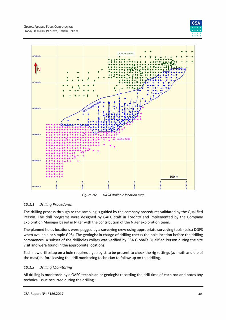
48
GLOBAL ATOMIC FUELS CORPORATION
DASA URANIUM PROJECT, CENTRAL NIGER
CSA-Report Nº: R186.2017
Figure 26: DASA drillhole location map
10.1.1 Drilling Procedures
The drilling process through to the sampling is guided by the company procedures validated by the Qualified
Person. The drill programs were designed by GAFC staff in Toronto and implemented by the Company
Exploration Manager based in Niger with the contribution of the Niger exploration team.
The planned holes locations were pegged by a surveying crew using appropriate surveying tools (Leica DGPS
when available or simple GPS). The geologist in charge of drilling checks the hole location before the drilling
commences. A subset of the drillholes collars was verified by CSA Global’s Qualified Person during the site
visit and were found in the appropriate locations.
Each new drill setup on a hole requires a geologist to be present to check the rig settings (azimuth and dip of
the mast) before leaving the drill monitoring technician to follow up on the drilling.
10.1.2 Drilling Monitoring
All drilling is monitored by a GAFC technician or geologist recording the drill time of each rod and notes any
technical issue occurred during the drilling.

49
GLOBAL ATOMIC FUELS CORPORATION
DASA URANIUM PROJECT, CENTRAL NIGER
CSA-Report Nº: R186.2017
During diamond drilling, a GAFC geologist supervises the drilling being physically present on drilling site.
Rotary Drilling
On a rotary drill rig, the rock chips come out with the mud. The drill company workers collect the drill chips
from the drill pipe at the hole collar every metre and arrange them in individual piles for the lithological
logging. Since 2014, part of the chips of each 1 m run are washed and put in the chip tray for further
description and archives in the core shed at the GAFC base camp.
Each metre run is tested with the handheld radiometric scanner by GAFC workers. The depth and the
radiometric counts are recorded. For earlier holes, these records were not always kept for use in further depth
corrections (lithology versus gamma probe depth). Comments are recorded on recovery and suspected
contamination.
Diamond Drilling
For diamond drilling, it is GAFC procedure to have a geologist physically present for the drill supervision with at
least one technician. For each run, GAFC Technician collects the core from the drillers. The core is cleaned and
laid down in the core box on which the technician has prior written the hole ID, and box number. Cores are
arranged as they would be in situ. A wooden or plastic block is placed at the end of each run recoding the depth.
The recovered core is measured to state the recovery percentage. Any detected core loss is recorded marked
with a tag indicating the length of core loss. The core depth is then marked on the core at 1 m intervals.
When an orientation survey is done, the core is marked by the geologist using a solid line with arrows pointing
downhole as orientation survey marks. When the core orientation is not reliable, the core is marked using a
broken line with arrows pointing downhole. All diamond drillholes from 2012 were oriented using an ACT II
Reflex tool when ground condition allowed it.
Each core run is scanned using a Thermo Scientific RADEye PRD–ER to record the radiometric response in
counts per second (Cps). Measurements are taken at 10 cm intervals for 5–10-second duration. The exposure
time can vary up to 10 seconds when the count rate is over 200 Cps.
The core is collected daily and transported to the core storage facility for detailed geological logging and
photographed (Figure 27) at the dedicated core photography facility.
Figure 27: Diamond core photograph example

50
GLOBAL ATOMIC FUELS CORPORATION
DASA URANIUM PROJECT, CENTRAL NIGER
CSA-Report Nº: R186.2017
Downhole Survey
During investigation of uranium projects, the following list of downhole geophysical surveys are commonly
used to help refine the geology of the deposit:
• Gamma-ray logging (GR)
• Electrical methods (resistivity logging (RL) and spontaneous polarisation (SP) logging)
• Directional survey (DS)
• Calliper logging (CL)
• Prompt fission neutron logging (PFN).
During exploration and evaluation, GAFC has used some of these methods and the results and methods are
discussed in the following sections.
10.2.1 Gamma-Ray Logging
GR was done routinely in the open hole conditions. In most holes (rotary or diamond core), the holes were
filled with water or mud. In areas of problematic ground conditions, the logging was done inside the drill
string or casing.
Several probes were used on the project for the gamma logging. The parameters of each are summarized in
Table 7.
Holes DADH-081 and DADH-011 were used as calibration holes. Each hole was logged once a week to calibrate
the gamma tool.
The majority (97%) of downhole logs were interpreted in Germany by Terratec Geophysic Services; the
remaining 3% of holes were interpreted by Semm Logging in France. The logging companies were based at
the GAFC base camp and all logging was started within 30–60 minutes of completion of the drillhole.
Table 7: Gamma-ray probe parameters
PROBE IDProbe K
factor (U)
Probe
diameter
(mm)
Mud
shielding
factor
(mm-1)
Probe
dead-
time (s)
Casing
shielding
factor
(mm-1)
Probe_length
(mm)CRISTAL reference
DIL38 #1125 0.1305 38 0.0047 0.000004 0.043 2120 1”x 2” NaI crystal
DIL38 #1126 0.1305 38 0.0047 0.000004 0.043 2120 1”x 2” NaI crystal
DIL38 #1250 0.1362 38 0.0047 0.000004 0.043 2120 1”x 2” NaI crystal
DIL38#801 0.126 39 0.0047 0.000004 0.043 2120 1”x 2” NaI crystal
BDVG #735 0.1119 42 0.0047 0.000004 0.043 140 1”x 2” NaI crystal
DGGG1307, PM 0.8089 42 0.0047 0.000004 0.043 150 2cmx5cm NaI
DGGG1304, PM 0.8089 42 0.0047 0.000004 0.043 150 2cmx5cm NaI
DGGG9354, PM 0.8089 42 0.0047 0.000004 0.043 150 2cmx5cm NaI
Prior to 2014, a logging protocol was not clearly defined. Based on investigation by CSA Global most work
comprised dual induction and gamma log measurements (DIL). The logging speed has been estimated at 3 m
to 4 m per minute, which was deduced from the time spent on hole logging. Sampling intervals varied from
0.01 m; 0.05 m or 0.1 m.

51
GLOBAL ATOMIC FUELS CORPORATION
DASA URANIUM PROJECT, CENTRAL NIGER
CSA-Report Nº: R186.2017
Starting in 2014, Terratec geophysical services used the following logging methods:
• Dual induction and gamma log measurements of the rock conductivity; total count gamma was used for
the determination of the equivalent radiometric grades of eU3O8.
• Combination tool including verticality/focused electric resistivity/Natural Gamma (DGGG).
• The first measurement run was performed inside the fully cased borehole or drill string with the DGGG
or DIL probe with an approximate logging speed of 4–6 m/minute and a sampling rate of 0.1 m.
• After the rods were removed the drillhole was filled with water and re-logged using the Combined
Verticality/Focused Electric Resistivity/Gamma Probe (as long as the drillhole was still open). The
measurement speed of approximately 5.00 m/minute was used in un-mineralized intervals at a sampling
rate of 0.1 m. Within the mineralized zones, the logging speed was decreased to approximately
1.5 m/minute. One metre beneath the mineralized zones, the logging speed was increased again to
5 m/minute.
All the equivalent uranium oxide (eU3O8) was determined by GAFC consultants taking into account a steel
correction factor when the logging was completed inside the casing or drill rods. A report in *.LAS format was
sent to GAFC including the radiometric survey and the calculated eU3O8.
For quality and calibration control, the calibration holes were tested at least twice a month and always just
before probing a new drillhole. Records are kept by the contractor and delivered to GAFC.
Terratec has indicated that all probes used on the project are properly calibrated to a defined U-Standard.
One calibration U-Standard that was used is located in Saskatoon-Saskatchewan/Canada and a second one in
Straz Pod Ralskem/Czech Republic. The last available calibration report from Terratec is from September 2013
which returned good results and the calibration was performed at the Saskatchewan Research Council
Uranium Test Pits in Canada.
More detail discussion about eU3O8 and Radioactive Equilibrium Factor (REF) is provided in the Section 11.
10.2.2 Downhole Survey
Prior to year 2012, GAFC was drilling shallow holes, and no deviation surveys were completed. Since 2012, all
the holes drilled especially in the graben area were systematically measured for deviation (if the hole
remained open).
Both Terratec and SemmLogging recorded the azimuth and the dip of the drillhole at the same time as gamma
logging using a combination tool.
GAFC also owns a Ranger Explorer Mark II wireless magnetic multi-functional survey system that was used to
measure azimuth and inclination for drillholes not surveyed during downhole logging.
GAFC also rented a Reflex tool EZTRAC (same system as the RANGER Explorer), operated by its rig monitoring
technicians. Some holes were surveyed using this tool.
Each completed drillhole was marked on surface using a heavy cement concrete slab containing:
• The project company name: GAFC
• The hole name/number
• The hole type (DD, RD…)
• Total length (core length or the reconciled depth after comparing probe and handheld radiometric
scanner depth when rotary drilling)

52
GLOBAL ATOMIC FUELS CORPORATION
DASA URANIUM PROJECT, CENTRAL NIGER
CSA-Report Nº: R186.2017
• The azimuth and dip
• The drill date (year).
The hole was then surveyed using the Leica DGPS or Total station by the surveying crew or appointed
technician/geologist.
10.2.3 Drillhole Diameter Measurements
CL was not routinely done. CSA Global recommends that all future downhole logging include this feature to
improve the gamma-logging interpretation. The interpretation of uranium grades from gamma-logging
includes hole diameter. The cavities could also influence the interpretation results and ultimately the
calculated uranium grades.
10.2.4 PFN Logging
PFN logging was not done. CSA recommends a selection of future drillholes to try this method to assess
radiological disequilibrium.
Rotary Chips and Core Logging
GAFC uses CAE Mining’s commercial data management software called Fusion. GAFC uses four main modules
of Fusion for data capture and storage:
• FUSION ADMINISTRATOR: To manage user rights and data transfer instructions.
• DHLOGGER: For logging the geology, structure and geotechnical aspects; for both core and chip logging.
It is also used to merge downhole logging and assay import and depth correction.
• FUSION CLIENT: To facilitate data transfer from the field to the office server (intermediate based in Niger
and called Fusion Remote, and Central based in Toronto).
• QUERY BUILDER: To export stored data for external use.
The workflow for this system is summarized in Figure 28.
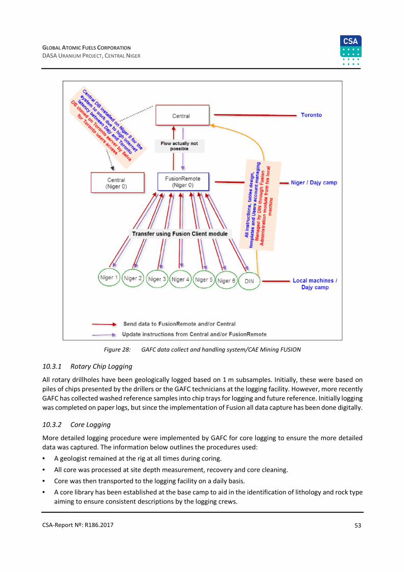
53
GLOBAL ATOMIC FUELS CORPORATION
DASA URANIUM PROJECT, CENTRAL NIGER
CSA-Report Nº: R186.2017
Figure 28: GAFC data collect and handling system/CAE Mining FUSION
10.3.1 Rotary Chip Logging
All rotary drillholes have been geologically logged based on 1 m subsamples. Initially, these were based on
piles of chips presented by the drillers or the GAFC technicians at the logging facility. However, more recently
GAFC has collected washed reference samples into chip trays for logging and future reference. Initially logging
was completed on paper logs, but since the implementation of Fusion all data capture has been done digitally.
10.3.2 Core Logging
More detailed logging procedure were implemented by GAFC for core logging to ensure the more detailed
data was captured. The information below outlines the procedures used:
• A geologist remained at the rig at all times during coring.
• All core was processed at site depth measurement, recovery and core cleaning.
• Core was then transported to the logging facility on a daily basis.
• A core library has been established at the base camp to aid in the identification of lithology and rock type
aiming to ensure consistent descriptions by the logging crews.

54
GLOBAL ATOMIC FUELS CORPORATION
DASA URANIUM PROJECT, CENTRAL NIGER
CSA-Report Nº: R186.2017
• Special procedures were in place for the handling of radioactive core for logging and sampling. The
procedures are available in hard copy in the logging facility.
• Radioactive core was hand scanned with a personal radiation detector to allow comparison with the down hole probing. The radiometric core was taken from the box and hand scanned every 10 cm on a table
inside the core shed. Measurements were recorded in an Excel spreadsheet.
• The core boxes were laid down on the logging table at the core shed and descriptions were made using DHLOGGER. When geological logging was complete, then the core was marked for geotechnical logs when
the core was oriented.
• Each hole was then marked up sampling.
• All core was photographed in a dedicated facility and transferred to the commercial TEC-CORIM software
allowing image manipulation including transfer to the Fusion database.
Geological logging was completed for the following attributes:
• Geological formations (Table 8)
• Colour (Table 9), which is important for definition of initial reduced sediments and epigenetic oxidized
rocks
• Sediments/rocks (Table 10)
• Alteration and mineralisation (Table 11).
Table 8: Codes of geological formations
Table 9: Codes of colour

55
GLOBAL ATOMIC FUELS CORPORATION
DASA URANIUM PROJECT, CENTRAL NIGER
CSA-Report Nº: R186.2017
Table 10: Codes of sediments/rocks
Table 11: Codes of alteration and mineralisation
Sampling
No rotary chips were sampled for assaying.
For core sampling, a mineralized interval was established from the downhole logging. Prior to 2014 drilling,
the eU3O8 results were composited at 100 ppm cut-off (allowing 3 m internal dilution of grade lower than
100 ppm). The mineralized interval was sampled from 1 m above and below the interval. Starting in 2014, the cut-off grade was changed to 300 ppm from the downhole gamma logging and proceeding the same way as
the 100 ppm cut-off.
After geological and geotechnical logging of the core, the designated mineralized interval was marked for
sampling. Sampling was done to reflect the lithological contacts and then routinely at 1 m intervals and during
the most recent program holes this was reduced to 0.5 m intervals.
Sampling was lithological facies related: samples were taken in same lithological unit (each texture of
sandstone should be considered as separate lithological unit, mudstone etc.).

56
GLOBAL ATOMIC FUELS CORPORATION
DASA URANIUM PROJECT, CENTRAL NIGER
CSA-Report Nº: R186.2017
The sample number was written on each core sample using red marker pen. The marked cores were sent to
the splitting facility in the base camp where and half core was sampled, bagged and sealed for mechanical
preparation at the ISO 17025 certified Sahel Lab facility in Niamey. The remaining half core is kept in the core
boxes at the base camp. Pulp was shipped from Sahel Lab to an assay facility in Canada.
According to Niger mining legislation, half of any core collected on mining/exploration project is dedicated to
the ministry of mines, unless you get a special authorization to use the entire core. GAFC has sought such authorization for some of their sampling. Subject to the ministry of mines authorization, the full core of each
marked length was broken and sampled.
A 5–10 cm piece of sample was taken for specific gravity test prior to bag and seal the to-be assayed sample.
Each sample was packed in dedicated plastic bag on which the sample number was marked on both sides. A
GAFC designed sample tag with the sample number printed on it was also inserted into the bag and sealed.
The sample numbering was designed to include 10% QC material:
• Certified reference materials (from ORE Research & Exploration Pty Ltd, Australia) were inserted in the
sampling at a rate of five per 100 samples
• Certified blank material (from ORE Research & Exploration Pty Ltd, Australia) was inserted at a rate of 2%
• Blank material sourced from rocks near Niamey was inserted at a rate of one per 100 samples
• Pulp duplicate samples taken from the same half-core sample were made for two out of every 100
samples and submitted for analysis.

57
GLOBAL ATOMIC FUELS CORPORATION
DASA URANIUM PROJECT, CENTRAL NIGER
CSA-Report Nº: R186.2017
11 Sample Preparation, Analyses and Security
Sample Preparation and Analyses
Core sampling was undertaken by GAFC staff. Samples were collected from quarter (before 2013)/half core
and appropriately bagged and labelled. Samples were sent by truck to the Sahel Laboratory in Niamey for preparation. Until April 2013, pulps prepared by the Sahel Laboratory were sent to ALS Geochemistry in
Johannesburg, South Africa for analyses. From April 2013 onwards, pulps have been sent to ALS Geochemistry
in North Vancouver, Canada for analyses.
The Sahel Laboratory in Niamey is accredited ISO 17025:2005 by Universal Registrars, Bangalore, India for
sample preparation. Both ALS Minerals laboratories in Johannesburg and in North Vancouver are also
accredited ISO-9001:2000 by QMI Management Systems and to ISO/IEC Guideline 17025:2005 by the
Standards Council of Canada for conducting certain testing procedures. The scope of accreditation includes
the procedures used for assaying of the samples submitted by GAFC. ALS laboratories also participates in a
number of international proficiency tests, such as those managed by CANMET and Geostats. All laboratories
where analyses have occurred are independent of the issuer and qualified person.
At Sahel Laboratory samples were prepared using a standard rock preparation procedure. Quarter or half
core was ground using a jaw crusher until 95% of the material passed a 2 mm mesh. One-eighth of this was
taken and pulverized until 90% of the material passed through a 75-micron mesh. One-hundred grams of the
resulting pulp is sent to the ALS laboratory for assay. The remaining rejects were returned to GAFC and
transported back to the field camp for storage.
Up until April 2013, prepared pulp samples were sent to ALS Geochemistry in Johannesburg and were assayed
for a suite of elements (including uranium) using inductively coupled plasma atomic emission spectroscopy
(ME-ICP61) and XRF spectroscopy (ME-XRF05).
In April 2013, prepared pulp samples were sent to ALS Geochemistry in North Vancouver, where samples
were assayed for uranium using XRF spectroscopy (ME-XRF05; ME-XRF10).
The switch between ALS laboratories was made primarily to gain access to the XRF10 method of assaying,
which can measure more accurately the concentration of uranium exceeding 10,000 ppm. The XRF05 method
used in South Africa is accurate to concentrations of uranium up to 10,000 ppm.
The SGS Lakefield laboratory in Lakefield, Canada was used as an umpire laboratory. The SGS laboratory in
Lakefield, and Mintek laboratories in Randburg, South Africa were also used to conduct metallurgical testing
on surface and core samples representative of the uranium mineralization found on the DASA Project. The
SGS Lakefield and Mintek laboratories are accredited ISO-9001 and to ISO Guideline 17025 for the testing
procedures undertaken on material from the DASA Project.
Specific Gravity Data
During the 2012 to 2015 drilling campaigns, GAFC hired the ISO 17025 certified laboratory, SAHEL Lab in Niger,
to perform specific gravity test on core samples. A total of 3,594 core samples sizing about 5 cm each were
submitted during the concerned period and this gives an average specific gravity value of 2.36 t/m3. The
density of 2.36 was thus used for the current study.
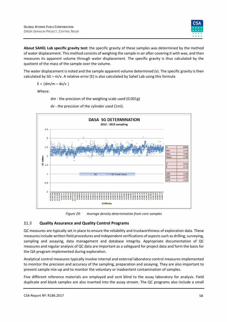
58
GLOBAL ATOMIC FUELS CORPORATION
DASA URANIUM PROJECT, CENTRAL NIGER
CSA-Report Nº: R186.2017
About SAHEL Lab specific gravity test: the specific gravity of these samples was determined by the method
of water displacement. This method consists of weighing the sample in air after covering it with wax, and then
measures its apparent volume through water displacement. The specific gravity is thus calculated by the
quotient of the mass of the sample over the volume.
The water displacement is noted and the sample apparent volume determined (v). The specific gravity is then
calculated by SG = m/v. A relative error (E) is also calculated by Sahel Lab using this formula
E = |dm/m – dv/v |
Where:
dm - the precision of the weighing scale used (0.001g)
dv - the precision of the cylinder used (1ml).
Figure 29: Average density determination from core samples
Quality Assurance and Quality Control Programs
QC measures are typically set in place to ensure the reliability and trustworthiness of exploration data. These
measures include written field procedures and independent verifications of aspects such as drilling, surveying,
sampling and assaying, data management and database integrity. Appropriate documentation of QC measures and regular analysis of QC data are important as a safeguard for project data and form the basis for
the QA program implemented during exploration.
Analytical control measures typically involve internal and external laboratory control measures implemented
to monitor the precision and accuracy of the sampling, preparation and assaying. They are also important to
prevent sample mix-up and to monitor the voluntary or inadvertent contamination of samples.
Five different reference materials are employed and sent blind to the assay laboratory for analysis. Field
duplicate and blank samples are also inserted into the assay stream. The QC programs also include a small

59
GLOBAL ATOMIC FUELS CORPORATION
DASA URANIUM PROJECT, CENTRAL NIGER
CSA-Report Nº: R186.2017
check assaying program at the SGS laboratory in Lakefield, Canada, which is ISO/IEC 17025 accredited. The
check assaying program is not undertaken on an ongoing basis.
Comparison of ordinary assays of certified reference material samples with control limit parameters is shown
in the Table 12. Results show that quality of sampling and assaying is acceptable. Comparison of ordinary
samples and duplicates is provided in the QAQC reports on DASA Project (2012, 2013) (Figure 30).
Table 12: Comparison of ordinary assays of certified reference material samples with passport parameters
Number of CRM Parameters of CRM Ordinary assays of CRM samples
LL Nom UL NN Minimum Average Maximum
ALS Johannesburg
AMIS0028 4,200 4,670 5,150 5 4,220 4,382 4,590
AMIS0054 1,320 1,470 1,620 8 1,385 1,456 1,480
AMIS0090 809 903 997 4 880 884 889
AMIS0098 774 848 922 8 850 855 865
AMIS0114 491 550 609 9 521 538 542
GBM908-5 4 5 5 14 4 15 128
GEOMS-03 3 4 4 4 3 4 5
MRGeo08 5 6 6 19 4 6 9
SARM-98 181 205 230 12 198 200 205
UTS-1 44 49 54 10 36 45 52
ALS Vancouver
BL-1 210 220 230 89 200 216 231
BL-4a 1,241 1,248 1,255 88 1,205 1,238 1,290

60
GLOBAL ATOMIC FUELS CORPORATION
DASA URANIUM PROJECT, CENTRAL NIGER
CSA-Report Nº: R186.2017
Figure 30: Comparison of the ordinary samples and duplicates for the DASA Project

61
GLOBAL ATOMIC FUELS CORPORATION
DASA URANIUM PROJECT, CENTRAL NIGER
CSA-Report Nº: R186.2017
Radioactive Equilibrium Factor
Geophysical gamma logging data is the primary information source used for uranium resources estimation.
From these data, it is then possible to determine:
• Mineralised intervals based on gamma logging data
• Conversion of radium grade to uranium based on REF.
REF = С (radium) / С (uranium) should be estimated based on uranium assays and radium assays sampled into
closed cans. But radium grades were not determined. In this situation comparison of the eU3O8 based on
gamma logging and aU3O8 based on assays may be used for determination of REF. This is possible by using
the scintillometer readings made on the core to compare and correct gamma logging data.
The average grade of potassium is 1.91% (0.01–6.39%) and thorium is 25 ppm (0.6–417 ppm), equals 25 ppm
of uranium.
In practical experience grade-thickness is a more convenient parameter for REF definition:
REF = GT (radium) / GT (uranium).
The total grade-thickness eU3O8 based on gamma logging is 171 m% and aU3O8 based on assays is 175 m%,
REF = 0.97.
Comparison of eU3O8 based on gamma logging and aU3O8 based on assays shows acceptable correlation close
to 1 (Figure 31), coefficient of correlation is 0.96, precision is 100%.
Generally, mineralisation on the DASA project is close to equilibrium, but this does vary of the project area
(Figure 32).

62
GLOBAL ATOMIC FUELS CORPORATION
DASA URANIUM PROJECT, CENTRAL NIGER
CSA-Report Nº: R186.2017
Figure 31: Comparison of grade-thickness eU3O8 defined by gamma logging and grade-thickness U3O8 defined by
assays
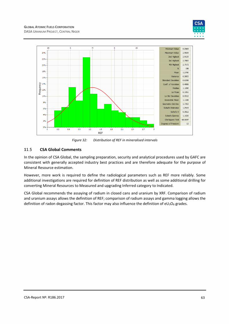
63
GLOBAL ATOMIC FUELS CORPORATION
DASA URANIUM PROJECT, CENTRAL NIGER
CSA-Report Nº: R186.2017
Figure 32: Distribution of REF in mineralised intervals
CSA Global Comments
In the opinion of CSA Global, the sampling preparation, security and analytical procedures used by GAFC are
consistent with generally accepted industry best practices and are therefore adequate for the purpose of
Mineral Resource estimation.
However, more work is required to define the radiological parameters such as REF more reliably. Some
additional investigations are required for definition of REF distribution as well as some additional drilling for
converting Mineral Resources to Measured and upgrading Inferred category to Indicated.
CSA Global recommends the assaying of radium in closed cans and uranium by XRF. Comparison of radium
and uranium assays allows the definition of REF; comparison of radium assays and gamma logging allows the
definition of radon degassing factor. This factor may also influence the definition of eU3O8 grades.
64
GLOBAL ATOMIC FUELS CORPORATION
DASA URANIUM PROJECT, CENTRAL NIGER
CSA-Report Nº: R186.2017
12 Data Verification
Dmitry Pertel visited the Project site from 20 March 2017 through to 6 April 2017. During the visit, Dmitry
Pertel reviewed geological reports, drilling procedures and surveys, logging facilities and overall deposit
geology. Geological exploration drilling procedure, core recovery methods and documentation and
geophysical logging have been analysed from the provided reports.
During the site visit, the QP observed a number of drill collars, took their photographs and geographic
coordinates. The measured coordinates were compared with those reported in the provided database. The difference between the measured and reported coordinates were within the acceptable limits.
From 2 March 2017 through 4 April 2017, Dmitry Pertel visited the Sahel Laboratory in Niamey, and had an
opportunity to interview the personnel there. The laboratory was in the middle of the relocation process, and
therefore it was not possible to observe the working equipment which was all dismantled at the time of the
inspection.
CSA Global has reviewed the drill logs, cross-sections, plan maps for the DASA geological database.
All work relating to geological exploration and leach testing was found to be of a high quality. The data is
considered suitable for Mineral Resource estimation.
Caution should be exercised when estimating Mineral Resources based on geophysical data due to the
complex radiology of the deposits.

65
GLOBAL ATOMIC FUELS CORPORATION
DASA URANIUM PROJECT, CENTRAL NIGER
CSA-Report Nº: R186.2017
13 Mineral Processing and Metallurgical Testing
Mineral processing and metallurgical testing was conducted by GAFC from 2011 to 2014. A summary was
prepared by Fergus P Kerr, P.Eng.
Testing was conducted on samples obtained from the DASA Project by GAFC at various stages of the Mineral Resource development. The samples were located as representative of the Mineral Resource known at that
time. Samples were obtained from diamond drillholes by GAFC personnel and shipped in core boxes or in rice
bags secured with security seals to SGS Mineral Services, Lakefield, Ontario, Canada and Mintek, Randburg,
South Africa.
SRK Consulting (UK), SRK Consulting (Australia) and Hatch (Mississauga) have provided technical support and
review of the mineral processing and metallurgical testwork.
Three separate investigations were conducted:
1. Characterization studies: In 2011, samples were obtained from diamond drillholes in various portions of the upper mineralisation to determine variability and metallurgical characteristics of the DASA 1 and DASA 3 areas. SGS conducted testing on five samples from five different holes in the DASA 1 and DASA 3 areas, including comminution studies, variability leach testing, precipitation, uranium recovery and mineralogy. The head analysis of these samples was approximately 600 ppm U3O8.
2. Heap leach study: Samples were obtained as representative of the low-grade near-surface material with potential for heap leaching. Five samples were obtained for a total of 878 kg and shipped in 2012 to Mintek, South Africa by DHL Courier services. The head analysis of the samples was 250 ppm U3O8 which was close to the anticipated grade of the heap leach material.
Testwork conducted by Mintek included mineralogical analysis, bottle roll testing, scrubbing investigation, small and large diameter column leach tests and geomechanical testwork.
3. Agitated leach testing: samples were selected to represent the higher-grade mineralisation in the DASA 3 area. A total of eight samples from three drillholes, for a total weight of 110 kg, were shipped to SGS for additional leach testing of the higher-grade material and additional Bond Work Index (BWI) testing to confirm the grindability from previous comminution studies. The head analysis of these samples was from 1200–1900 ppm U3O8.
No testing has been conducted on the potential high-grade underground mineralisation.
Comminution
SGS conducted testwork on two samples from the DASA project – one composite sample from DASA 1 and
DASA 3 drillholes and one composite sample from DASA 3 area.
The first samples were tested for the entire suite of comminution tests including abrasion test, BWI tests, high
pressure grinding roll test, JK drop-weight, SAG mill comminution test, SAG power index, static pressure test
and derivation of Comminution Economic Evaluation Tool (CEET).
The second samples were tested for BWI to confirm results from the lower grade testing. The results were
consistent with other BWI results.

66
GLOBAL ATOMIC FUELS CORPORATION
DASA URANIUM PROJECT, CENTRAL NIGER
CSA-Report Nº: R186.2017
Test results indicate the material is categorised as soft to very soft, except for the Crusher Work Index (CWI)
which is categorised as moderately hard. Results include the following:
• CWI 11.5 kWh/t
• BWI 16.1 kWh/t
• Abrasion Index 0.096 g
• Static Pressure test 1.42 HPI (9.9 kWh/t)
• CEET 15.9 Cl.
Leaching
Extensive leach testing was conducted at SGS Mineral Services and Mintek including bottle roll, agitated leach,
two stage leaching, scrubbing and column leach testing with both acid and alkaline leach conditions. Intent
of the testing was to understand the leach kinetics of the samples and develop potential leach flowsheets.
Bottle roll testing showed uranium extraction of 78% to 86% for tests run at 20 g/litre free acidity.
Bottle roll testing to determine variability of the leach kinetics of 30 separate samples showed uranium
extractions of 30% to 95% with an average of 73% and acid consumption of 33 kg/t to a high of 273.3 kg/t and
average of 115 kg/t. It was noted that samples with extraction below 50% had low uranium concentration.
Lower acidity testing showed comparable extraction over a longer time.
The best uranium extraction was achieved with high acid and high temperature – 80 g/litre sulphuric acid and
90°C gave extractions over 97%.
Carbonate leaching gave poor extraction of 68%.
Two stage counter-current leach reduced acid consumption by half at 90% extraction.
Grinding of the ore was not required to achieve high uranium extractions: <10 mesh (1.7 mm) ore leached
under high acid and temperature gave extraction at or better than 95%.
Work at Mintek indicated scrubbing was not effective on the very low-grade samples. Bottle roll tests showed
that acid-in-agglomeration and curing had a positive effect on the initial kinetics and extent of overall uranium
dissolution in acidic conditions.
An alkaline leach test at Mintek indicated only 62% recovery after73 days of leaching, similar to results at SGS.
Heap leach test results showed an 80% recovery with acid consumption of 50 kg acid per ton was achievable
after 17 days. Stacking tests and hydraulic conductivity testwork indicated stacking heights of the leach
material of 5–7 m were achievable.
Agitated leach testing at SGS showed uranium recovery of 93% was achievable for the higher-grade samples
at a pH of 1.5, 44ºC, and a grind P80 of 170 μm after 24 hours and sulphuric acid addition of 53 kg/t. An
additional higher grade sample showed a uranium recovery of 90% at 70ºC and acid consumption as high as
250 kg/t. Leach kinetics indicates no significant increase in extraction after eight hours.
Using two-stage leaching to utilise excess free acid and averaging the results from the two composite samples
suggests a recovery of 95% at an acid consumption of 180 kg/t would be a conservative estimate of leach
recovery.
The pregnant leach solutions had no significant levels of impurities (<0.6 mg/L Mo, <10 mg/L V).
67
GLOBAL ATOMIC FUELS CORPORATION
DASA URANIUM PROJECT, CENTRAL NIGER
CSA-Report Nº: R186.2017
Solid-Liquid Separation
A bulk leach sample was generated from the uranium leach tests and subjected to flocculent selection, CCD
modelling, vacuum filtration thickener and washed thickener underflow testing.
The optimum flocculent was Ciba Magnafloc 333 (a non-ionic flocculent) at a dose rate of 60 ppm and
produced a 48% w/w solids underflow from a 6% w/w solids thickener feed. The resulting supernatant was
clear after 10 minutes settling time. Settling rates of 1,135 to 1,219 m3 per m2 per day were measured.
Rheology testing indicated critical solids density was approximately 55% weight corresponding to 60 Pa yield
stress value (unsheared) for the bulk leach pulp at -30 mesh.
CCD scenario testing resulted in a water requirement of 1.59 to 3.21 m3 fresh water per tonne of dry feed
depending on the number of stages (5-7) and the wash efficiency required. The final stage discharge varied
between 0.001 and 0.007 g uranium per litre.
The direct filtration scoping tests conducted with, and without, a filter aid indicate the sample was not
amenable to direct filtration.
Solvent Extraction and Ion Exchange
Uranium was recovered from solution effectively using commercial tertiary amine extractant. When
aggressive leach conditions were used, the phase separation and clarity of phases suffered but efficient
extraction was achieved. Counter-current stripping of loaded organic with 400 g per litre H2SO4 was
performed at O/A of 10/1 producing strip liquor containing 31 g uranium per litre.
Several strong base anionic exchange resins were found to effectively absorb uranium from the leach solution,
achieving loadings upwards of 50 g uranium per litre.
Ambersep 920U was effectively stripped with 160 g/litre H2SO4 resulting in a strong eluate of 6 g uranium per
litre.
Resin-in-pulp (RIP) was tested as an alternative to leaching followed by solid-liquid separation. A660 resin
performed well, loading to 40 g/litre and achieving 99.7% uranium recovery from solution after four contacts
of two hours each.
Selection of uranium extraction methods will depend on the tenor and characteristics of the pregnant leach
solution. At lower grade feed, Ion Exchange will be used for uranium recovery.
Uranium Precipitation
Strip liquors from SX testing were used for uranium precipitation testing. The strip liquors were neutralised
with hydrated lime and advanced to precipitation using hydrogen peroxide. The final precipitate (yellowcake)
contained 64.3% uranium, equivalent to 91% uranyl peroxide.
Tailings Characterization
The tailings from the leach process were neutralized in two stages with limestone and lime to a pH of 9.
Samples of the tailings were taken for multi-element and Radium analysis with both below effluent standards.
68
GLOBAL ATOMIC FUELS CORPORATION
DASA URANIUM PROJECT, CENTRAL NIGER
CSA-Report Nº: R186.2017
Metallurgical Testing — Conclusion and Recommendations
Results of the metallurgical testwork shows the mineralogy and metallurgy of the DASA mineralisation is
readily amenable to acid leaching with conventional uranium recovery – similar to the AREVA operation at
Arlit, Niger.
Fine grinding is not required for acceptable uranium recovery; a grind to P80 of 170 μm is adequate.
Two-stage leaching with pre-leaching of the fresh ore with strong acid reduces acid consumption and will
recover over 90% of the uranium, recovery will improve with higher temperatures and grades. Acid
consumption is related to head grade.
Leach slurries can be separated effectively using conventional thickeners and flocculants.
Depending on the head grade and tenor of the pregnant leach solution IX or SX would be used for uranium
recoveries achieving over 99% recovery of the uranium.
Hydrogen peroxide precipitation is effective. No impurities have been detected in either the final precipitate
or in the tailings.
Based on the results the following recommendations are made:
• Leaching testwork is required on the high-grade underground resource.
• Mineralogical and metallurgical testing is required of the Tchirezine 2 and Tarat hosted mineralization.
• The discharge slurries from the leach tests should be subjected to solid liquid separation testing. Rheology
testing of the slurries is required to determine maximum pulp density of the leach.
• Mass balance modelling of the two-stage leach is required to better quantify acid consumption.
• At higher head grades uranium recovery testing is required.
• Further environmental characterisation of the leach residue and neutralisation products should be
conducted.
The testing recommended is bench scale testing and would require 40–50 kg of fresh material:
• Pre-concentration methods should be investigated; radiometric sorting or ablation could dramatically
reduce the mass pull to the processing facility with significant reduction in capital and operating costs.

69
GLOBAL ATOMIC FUELS CORPORATION
DASA URANIUM PROJECT, CENTRAL NIGER
CSA-Report Nº: R186.2017
14 Mineral Resource Estimates
Software Used
The DASA uranium deposit Mineral Resources were estimated by CSA Global geologists using Micromine
version 2016.1 software (Licence ID: MM2747).
Database Compilation
GAFC supplied CSA Global with the database in Text CSC format. The database included all the exploration
results for all exploration stages. The main analytical database comprises estimated uranium equivalent
grades (eU3O8) based on the gamma-logging of the drillholes.
The eU3O8 grades were calculated from the LAS files (gamma-logging results). LAS files included counts per
second (CPS) values, which were converted to U3O8 grades using standard corrections and coefficients that
account for the probe type (K-factor), casing steel thickness, presence of water and other factors. All other
correction factors and parameters are shown in Error! Reference source not found.Table 7.
The eU3O8 grades were calculated for each 10 cm interval using LAS files. Some holes were however not
gamma-logged to the total depth, but had results of the chemical assays which were also used for
interpretation and modelling. The available data is summarised in Table 13.
Table 13: Summary of supplied data
Category Amount
Drillholes 970
Metres drilled 123,914
Survey records 6,435
Records in assay data file, including 2,199,933
Assayed intervals for U3O8 (combined chemical assays and deconvolved grades) 2,169,554
Records in geology logging file 3,465
The databases consisted of several parts:
• Analytical database, including
o Drillhole collar coordinates
o Drillhole survey data
o Drillhole sampling database (combined chemical assays and deconvolved uranium grades from
gamma logging)
o Drillhole geological logging and codes.
• Topography data in the form of a DTM (supplied as a DXF file).
Import of the various datasets into Micromine proceeded without incident.
Data Validation
The analytical database was checked using macros and processes designed to detect the following errors:
• Duplicate drillhole names
• One or more drillhole collar coordinates missing in the collar file

70
GLOBAL ATOMIC FUELS CORPORATION
DASA URANIUM PROJECT, CENTRAL NIGER
CSA-Report Nº: R186.2017
• FROM or TO missing or absent in the assay file
• FROM > TO in the assay file
• Sample intervals are not contiguous in the assay file (gaps exist between the assays)
• Sample intervals overlap in the assay file
• First sample is not equal to 0 m in the assay file
• First depth is not equal to 0 m in the survey file
• Several downhole survey records exist for the same depth
• Azimuth is not between 0 and 360° in the survey file
• Dip is not between 0 and 90° in the survey file
• Azimuth or dip is missing in survey file
• Total depth of the holes is less than the depth of the last sample.
It was found that 10 holes do not have analytical information. All these holes were excluded from the resource
estimation process.
Some holes had negative FROM values (gamma-logging started above hole collars). All those intervals were
excluded from the database.
No other errors have been identified in the databases, and no corrections were introduced to the database.
Exploratory Data Analysis – Statistical Analysis
Classical statistical analysis was implemented twice for the deposit. The first study was carried out to
determine the distribution parameters of uranium grades.
Figure 33 summarise the statistical properties of the unrestricted assay databases for uranium. The statistical
parameters for all uranium grades are shown in Table 14.
The histogram for unrestricted uranium grade population has a positively skewed log distribution and
demonstrates that there is no apparent mixing of grade populations. The histogram does not show an obvious
cut-off grade that could be used for interpretation of uranium mineralization. A decision was made to employ
the nominal cut-off grade of 100 ppm for the subsequent interpretation of mineralized bodies. The adoption
of 100 ppm cut-off grade also reduces the residual effect of any radium halos by their exclusion.
Once the uranium mineralization was interpreted for all mineralized lenses and wireframed, classical
statistical analysis was repeated for the composited samples within the interpreted envelopes to meet the
following objectives:
• To estimate the mixing effect of grade populations for uranium within the interpreted mineralized bodies
• To estimate the necessity of separation of grade populations if more than one population was observed
• To reveal the possible top-cut grades for uranium for grade interpolation.
The input sample file was flagged to exclude those intervals that appeared outside the wireframed
mineralized envelopes for uranium. The modelled histogram for the uranium samples restricted within
mineralized envelopes does not demonstrate apparent mixing of grade populations for uranium (Figure 34).
The lognormal histograms and cumulative probability plots were analyzed to determine the top-cut grades to
be applied to the input analytical data before the geostatistical analysis. The majority of the input intervals
with uranium grades were determined from the gamma logging results for 10 cm intervals. Thus, a decision

71
GLOBAL ATOMIC FUELS CORPORATION
DASA URANIUM PROJECT, CENTRAL NIGER
CSA-Report Nº: R186.2017
was made that no-top cut grade values are applied on the analyzed intervals because deconvolving of uranium
grades from gamma-logging results usually takes into account abnormally high grades and, therefore, top-
cutting is not required.
Figure 33: Log histogram for unrestricted uranium grades
Figure 34: Log histogram for uranium grades within mineralised envelopes
The coefficient of variation for the composited uranium grades is close to 3, which indicates that the
possibility of modelling robust semi-variograms is relatively poor.

72
GLOBAL ATOMIC FUELS CORPORATION
DASA URANIUM PROJECT, CENTRAL NIGER
CSA-Report Nº: R186.2017
Table 14: Classical statistics for uranium grades (weighted on length)
Element Minimum
(ppm)
Maximum
(ppm)
No. of
points
Mean
(ppm) Variance
Standard
deviation
Coefficient
of variation
Median
(ppm)
eU3O8
Unrestricted sample intervals
0 65535 2169124 88 358464 599 9.7 16
Intervals within mineralized bodies
0 65535 189119 538 2619309 1618 4.1 183
0.5m composites within mineralized intervals
0 65535 28453 538 2580146 1606 3.0 180
Interpretation of Mineralized Bodies
The grade compositing process was employed to calculate the mineralised intervals using 100 ppm cut-off
grade. The calculated grade composites were displayed along the drillhole traces to assist with interpretation
only. The interpretation process involved correlation of identified mineralized intervals between the holes
along exploration lines and also between the sections to make sure that the correct lens numbers would
subsequently be assigned to the analytical data file.
The grade compositing process employed the following input parameters:
• Cut-off value 100 ppm eU3O8
• Minimum composite length 1 m
• Minimum grade of final composite 100 ppm eU3O8
• Maximum consecutive length of internal waste 0.5 m
• Minimum grade * length 200 ppm*m eU3O8.
Interpretation was carried out interactively for 56 SN cross-sections which were 50 m apart. When uranium
grades were interpreted, each section was displayed in Micromine’s Vizex display environment together with
drillhole traces, grade composites and interval grade values. A total number of 184 individual mineralized
lenses were interpreted for the deposit.
The following techniques were employed while interpreting the uranium mineralization:
• Each cross section was displayed on screen with a clipping window equal to a half distance from the
adjacent sections.
• All interpreted strings were snapped to the corresponding drillhole composited intervals, i.e. the
interpretation was constrained in the third dimension.
• Internal waste within the mineralized envelopes was not interpreted and modelled. It was initially
included in the composited grade intervals used for the resource estimation.
• The interpretation was extended perpendicular to the corresponding first and last interpreted cross
section to the distance equal to a half distance between the adjacent exploration lines. In this case, the
interpretation honoured the general direction of the structure and the tendency for changes of the form
of the geological body.
• If a mineralized envelope did not extend to the adjacent drillhole section, it was projected half way to the
next section keeping its thickness and terminated. The general direction and dip of the envelopes was
maintained.

73
GLOBAL ATOMIC FUELS CORPORATION
DASA URANIUM PROJECT, CENTRAL NIGER
CSA-Report Nº: R186.2017
• If a mineralized envelope did not extend to the next drillhole within the interpreted exploration line, it
was interpolated halfway to the next drillhole keeping its thickness and terminated. The general direction
and dip of the envelopes was maintained.
• If a mineralized envelope was at the topographic surface, it was extended above the topographic base.
This was done to make sure there would be no gaps between the block model and the topographic base
when the block model was built.
• When faults were interpreted along with the mineralized envelopes, mineralization was truncated by
interpreted fault planes.
Drillhole traces were also colour coded for the mail lithological types to assist with the interpretation. This
coding helped to understand and to interpret major fault systems and mineralized bodies displacements and
the edges of the graben.
An example of an interpreted section is shown in the Figure 35, where thick red lines along drillhole traces –
grade composites, traces are colour coded according to lithology, red strings – interpreted mineralized bodies,
purple lines – faults.
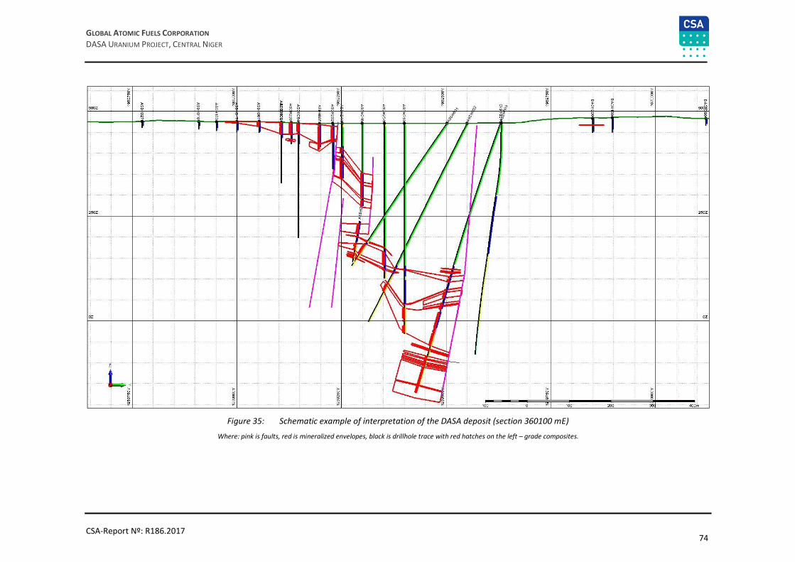
74
GLOBAL ATOMIC FUELS CORPORATION
DASA URANIUM PROJECT, CENTRAL NIGER
CSA-Report Nº: R186.2017
Figure 35: Schematic example of interpretation of the DASA deposit (section 360100 mE)
Where: pink is faults, red is mineralized envelopes, black is drillhole trace with red hatches on the left – grade composites.

75
GLOBAL ATOMIC FUELS CORPORATION
DASA URANIUM PROJECT, CENTRAL NIGER
CSA-Report Nº: R186.2017
Wireframing
The interpreted strings were used to generate 3D solid wireframes for the mineralized envelopes. Every cross
section was displayed on the screen along with the closest interpreted section. If the corresponding envelope
did not appear on the next cross section, the former was projected halfway to the next section, where it was
terminated. Every mineralized envelope was wireframed separately and individually. Mineralized bodies were
extended and projected to the interpreted sub-vertical fault planes, where it was possible, and then terminated. Internal waste was included within the interpretations where continuity would be improved by
doing so. Figure 36 is a 3D view of the modelled mineralized bodies. A total number of 184 wireframes were
modelled for the deposit. Each wireframed lens had a different colour, and steeply dipping faults are shown
with dark red colour on the figure. The modelled mineralized bodies between the faults generally represent
the graben structure, while all other bodies outside the graben are generally flat and relatively shallow
mineralized lenses.
Figure 36: Oblique view of the wireframed uranium mineralized envelopes and fault planes for the DASA deposit
(looking northwest)
All wireframe models were validated so that they are all solids (closed) and that they do not contain intersecting triangles.
Table 15: Number of interpreted wireframes at the DASA deposit
Number of wireframes Volume (m3)
184 51,388,105
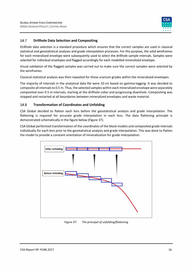
76
GLOBAL ATOMIC FUELS CORPORATION
DASA URANIUM PROJECT, CENTRAL NIGER
CSA-Report Nº: R186.2017
Drillhole Data Selection and Compositing
Drillhole data selection is a standard procedure which ensures that the correct samples are used in classical
statistical and geostatistical analyses and grade interpolation processes. For this purpose, the solid wireframes
for each mineralized envelope were subsequently used to select the drillhole sample intervals. Samples were
selected for individual envelopes and flagged accordingly for each modelled mineralized envelope.
Visual validation of the flagged samples was carried out to make sure the correct samples were selected by
the wireframes.
Classical statistical analysis was then repeated for those uranium grades within the mineralized envelopes.
The majority of intervals in the analytical data file were 10 cm based on gamma-logging. It was decided to
composite all intervals to 0.5 m. Thus, the selected samples within each mineralized envelope were separately
composited over 0.5 m intervals, starting at the drillhole collar and progressing downhole. Compositing was
stopped and restarted at all boundaries between mineralized envelopes and waste material.
Transformation of Coordinates and Unfolding
CSA Global decided to flatten each lens before the geostatistical analysis and grade interpolation. The
flattening is required for accurate grade interpolation in each lens. The data flattening principle is
demonstrated schematically in the figure below (Figure 37).
CSA Global performed transformation of the coordinates of the block models and composited grade intervals
individually for each lens prior to the geostatistical analysis and grade interpolation. This was done to flatten
the model to provide a constant orientation of mineralization for grade interpolation.
Figure 37: The principal of unfolding/flattening

77
GLOBAL ATOMIC FUELS CORPORATION
DASA URANIUM PROJECT, CENTRAL NIGER
CSA-Report Nº: R186.2017
Geostatistical Analysis
The purpose of geostatistical analysis was to generate a series of semi-variograms that can be used as the
input weighting mechanism for kriging algorithms. The semi-variogram ranges determined from this analysis
contribute heavily to the determination of the search neighbourhood dimensions. Therefore, geostatistical
analysis was conducted in order to:
• Estimate the spatial continuity of gold and silver grades in the main directions of anisotropy
• Obtain the semi-variogram parameters (nugget effect, total sill and ranges) to be input into the
interpolation process
• Obtain and analyse semi-variogram ranges which could be used to justify search ellipse radii.
Downhole experimental variogram was modelled to estimate the expected nugget effect for uranium grades
(Figure 38). The estimated nugget effect was then applied to model directional semi-variogram models.
A semi-variogram map was then generated in plan view to establish the direction of maximum grade
continuity (Figure 39). The map clearly demonstrated that the azimuth of maximum continuity is 55° which
generally matches with the overall strike of the mineralized bodies. Since the analytical data were flattened,
therefore, the directions for semi-variogram models were established as 55° azimuth, 0° dip; 145° azimuth,
0° dip; and vertical.
Figure 38: Downhole absolute semi-variogram model for uranium
It was found that robust absolute semi-variograms are difficult to model most likely due to the high coefficient
of variation of uranium grades. Therefore, relative semi-variogram models were calculated and modelled for
the composited uranium sample file without applied top cut grades (Figure 40).

78
GLOBAL ATOMIC FUELS CORPORATION
DASA URANIUM PROJECT, CENTRAL NIGER
CSA-Report Nº: R186.2017
Figure 39: Semi-variogram map (plan view)
Figure 40: Relative semi-variogram models for uranium (three main directions)
All modelled experimental semi-variograms were exponential and spherical with three nested structures. The
obtained semi-variogram ranges were used to determine the search radii. The latter were used in the grade
interpolation processes.

79
GLOBAL ATOMIC FUELS CORPORATION
DASA URANIUM PROJECT, CENTRAL NIGER
CSA-Report Nº: R186.2017
Table 16: Semi-variogram characteristics
Element Type Axis Azimuth Dip Nugget Partial sills Ranges
U3O8 Rel. Exp. and Spherical
Main 55 0
0.053 0.075, 0.241
and 0.255
4, 9.3 and 103.5
Second 145 0 14.5, 36.5 and 91.8
Third 145 90 1.52, 4.65 and 49.13
Block Modelling
An empty block model was created within the closed wireframe models for the mineralized envelopes. Each
modelled lens was assigned a unique code in the model file. The block model was then restricted below the
topography surface, i.e. all the model cells above the surface were deleted from the model file.
Block model parameters are shown in Table 17.
The initial filling with a corresponding parent cell size was followed by sub-celling where necessary. The sub-
celling occurred near the boundaries of the mineralization or where model was truncated with the
topographic surface. The parent cell size was chosen on the basis of the exploration grid and general
morphology of the mineralized bodies and in order to avoid the generation of excessively large block model.
The sub-celling size was chosen to maintain the resolution of the mineralized bodies. The sub-cells were
optimised in the model where possible to form larger cells.
Table 17: Block model characteristics
Axis Extent (m)
Block size (m) Maximum sub-celling (m) No. of parent blocks Minimum Maximum
Easting 358,740 361,460 20 2 136
Northing 1,968,240 1,970,560 20 2 116
RL -302 502 4 1 201
Grade Interpolation
eU3O8 grades were interpolated into the empty block model using the OK interpolation method. This was then
rerun using Inverse Distance Weighted (IDW) method with the powers of two and three as cross check.
The OK and IDW processes were performed at different search radii until all model cells were interpolated.
The search radii were determined by means of the evaluation of the semi-variogram parameters. Each
mineralized lens was estimated separately.
The first search radii for all lenses were selected to be equal to one-third of the semi-variogram long ranges
in all directions. Model cells that did not receive a grade estimate from the first interpolation run were used
in the next interpolation with greater search radii equal to two-thirds of semi-variogram long ranges in all
directions. The third interpolation run employed radii equal to full semi-variogram ranges. The model cells
that did not receive grades from the first three interpolation runs were then estimated using radii
incremented by the full semi-variogram ranges until all model cells were informed with uranium grade.
When model cells were estimated using radii not exceeding full semi-variogram ranges, a restriction of at
least three samples from at least two drillholes was applied to increase the reliability of the estimates. The
general definition of the interpolation strategy is presented in Table 18 below.

80
GLOBAL ATOMIC FUELS CORPORATION
DASA URANIUM PROJECT, CENTRAL NIGER
CSA-Report Nº: R186.2017
The blocks were interpolated using only assays restricted by the corresponding lens. De-clustering was
performed during the interpolation process by using four sectors within the search neighbourhood. Each
sector was restricted to a maximum of four points for all the lenses, and the search neighbourhood was
restricted to an overall minimum of three points from at least two drillholes for the interpolation runs using
radii within the semi-variogram ranges. The maximum combined number of points allowable for the
interpolation was therefore 16. Change of support was honoured by discretizing to 5-points x 5-points x 5-
points. These point estimates are simple averages of the block estimates. The general definition of the
interpolation strategy is presented in Table 18.
Table 18: Interpolation parameters
Interpolation method Ordinary kriging
Search radii Less or equal to
1/3 of semi-variogram ranges
Less or equal to 2/3 of semi-
variogram ranges
Less of equal to semi-variogram
ranges
2 semi-variogram
ranges
Greater than 2 semi-variogram
ranges
Minimum no. of points 4 4 4 1 1
Maximum no. of points 16 16 16 16 16
Minimum no. of drillhole 3 3 3 1 1
Density Values
Dry density values were obtained by previous and recent exploration programmes on the deposit and direct
measurements of 3,594 core samples taken and processed by GAFC. More information is provided in the
previous sections of this report (Section 11.2).
Density values can be assigned to block model cells using the following methods:
• Direct assignment of the values to block model cells
• Calculation of values for each cell using regression formulas
• Interpolation of values
• Use of geological model to assign values into each model cell.
CSA Global used the first method, i.e. the density values were assigned to each model cell based on the
average value from the density data set collected and provided by GAFC.
Each model cell was assigned a density value of 2.36 t/m3.
Mineral Resource Classification Strategy
The Resource classification strategy utilised in this report is based primarily on search and interpolation
parameters, and exploration drillhole density. Kriging variance was also used to assist with the classification.
The specific requirements concerning the minimum number of samples and minimum number of drillholes
used for grade interpolation for each block were applied, and are tabulated in Table 18.
The block model was displayed in Micromine’s Vizex environment and colour coded according to interpolation
runs. After visual inspection, it was decided that the classification of Mineral Resources could be based on
exploration drillhole density and interpolation runs which were based on modelled semi-variogram ranges. It
was decided that the exploration grid of at least 50 x 50 m would support the Indicated resource category if
blocks were estimated from at least two drillholes by search ellipse not exceeding semi-variogram ranges. All
the remaining model cells were classified as Inferred. No Measured Mineral Resource category was applied
to the DASA model.

81
GLOBAL ATOMIC FUELS CORPORATION
DASA URANIUM PROJECT, CENTRAL NIGER
CSA-Report Nº: R186.2017
The resource classification strategy is illustrated below (colours: green – Indicated, blue – Inferred) in
Figure 41.
Figure 41: Resource classification strategy (section 360100 mE)
Block Model Validation
The generated block model for the DASA deposit with interpolated uranium grades was validated both visually
and digitally. Close correlation between the sample grades and the model grades was observed.
The average block model grades were compared against average uranium grades in the sample composite
file. The modelled grades were very close to the average uranium grade in the sample composite file (2%
relative difference – 538 ppm in the composite file and 549 ppm in the model).
All grades were also interpolated using the IDW method with the power of two and three and then compared
to the grades estimated by OK method. A comparison of the grades and metal tonnage using OK vs. IDW method at various cut-off grades is given in Table 19 below. Kriging returned generally lower grades, but
overall the grades differ within acceptable limits.
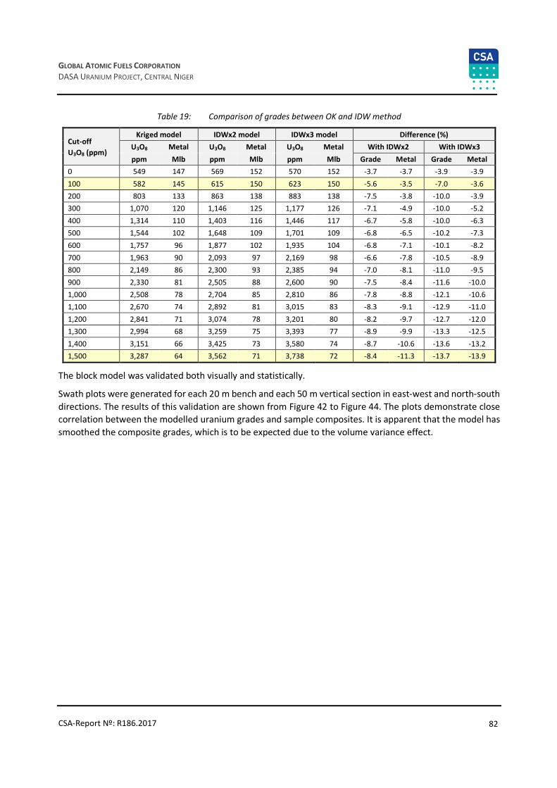
82
GLOBAL ATOMIC FUELS CORPORATION
DASA URANIUM PROJECT, CENTRAL NIGER
CSA-Report Nº: R186.2017
Table 19: Comparison of grades between OK and IDW method
Cut-off
U3O8 (ppm)
Kriged model IDWx2 model IDWx3 model Difference (%)
U3O8 Metal U3O8 Metal U3O8 Metal With IDWx2 With IDWx3
ppm Mlb ppm Mlb ppm Mlb Grade Metal Grade Metal
0 549 147 569 152 570 152 -3.7 -3.7 -3.9 -3.9
100 582 145 615 150 623 150 -5.6 -3.5 -7.0 -3.6
200 803 133 863 138 883 138 -7.5 -3.8 -10.0 -3.9
300 1,070 120 1,146 125 1,177 126 -7.1 -4.9 -10.0 -5.2
400 1,314 110 1,403 116 1,446 117 -6.7 -5.8 -10.0 -6.3
500 1,544 102 1,648 109 1,701 109 -6.8 -6.5 -10.2 -7.3
600 1,757 96 1,877 102 1,935 104 -6.8 -7.1 -10.1 -8.2
700 1,963 90 2,093 97 2,169 98 -6.6 -7.8 -10.5 -8.9
800 2,149 86 2,300 93 2,385 94 -7.0 -8.1 -11.0 -9.5
900 2,330 81 2,505 88 2,600 90 -7.5 -8.4 -11.6 -10.0
1,000 2,508 78 2,704 85 2,810 86 -7.8 -8.8 -12.1 -10.6
1,100 2,670 74 2,892 81 3,015 83 -8.3 -9.1 -12.9 -11.0
1,200 2,841 71 3,074 78 3,201 80 -8.2 -9.7 -12.7 -12.0
1,300 2,994 68 3,259 75 3,393 77 -8.9 -9.9 -13.3 -12.5
1,400 3,151 66 3,425 73 3,580 74 -8.7 -10.6 -13.6 -13.2
1,500 3,287 64 3,562 71 3,738 72 -8.4 -11.3 -13.7 -13.9
The block model was validated both visually and statistically.
Swath plots were generated for each 20 m bench and each 50 m vertical section in east-west and north-south
directions. The results of this validation are shown from Figure 42 to Figure 44. The plots demonstrate close
correlation between the modelled uranium grades and sample composites. It is apparent that the model has
smoothed the composite grades, which is to be expected due to the volume variance effect.

83
GLOBAL ATOMIC FUELS CORPORATION
DASA URANIUM PROJECT, CENTRAL NIGER
CSA-Report Nº: R186.2017
Figure 42: Swath plot for 50 m easting sections
Figure 43: Swath plot for 50 m northing sections
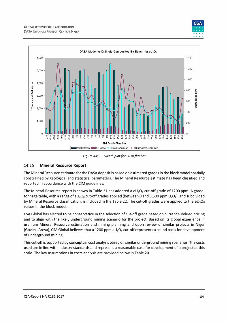
84
GLOBAL ATOMIC FUELS CORPORATION
DASA URANIUM PROJECT, CENTRAL NIGER
CSA-Report Nº: R186.2017
Figure 44: Swath plot for 20 m flitches
Mineral Resource Report
The Mineral Resource estimate for the DASA deposit is based on estimated grades in the block model spatially
constrained by geological and statistical parameters. The Mineral Resource estimate has been classified and
reported in accordance with the CIM guidelines.
The Mineral Resource report is shown in Table 21 has adopted a eU3O8 cut-off grade of 1200 ppm. A grade-
tonnage table, with a range of eU3O8 cut-off grades applied (between 0 and 3,500 ppm U3O8), and subdivided
by Mineral Resource classification, is included in the Table 22. The cut-off grades were applied to the eU3O8 values in the block model.
CSA Global has elected to be conservative in the selection of cut-off grade based on current subdued pricing
and to align with the likely underground mining scenario for the project. Based on its global experience in
uranium Mineral Resource estimation and mining planning and upon review of similar projects in Niger
(Goviex, Areva), CSA Global believes that a 1200 ppm eU3O8 cut-off represents a sound basis for development
of underground mining.
This cut-off is supported by conceptual cost analysis based on similar underground mining scenarios. The costs
used are in line with industry standards and represent a reasonable case for development of a project at this
scale. The key assumptions in costs analysis are provided below in Table 20.

85
GLOBAL ATOMIC FUELS CORPORATION
DASA URANIUM PROJECT, CENTRAL NIGER
CSA-Report Nº: R186.2017
Table 20: Conceptual cost analysis
Units
Mining rate per day tonnes 2,000
Price $/lb 50
OPEX $/tonne
Mining, ore 33
Processing 53
Transport 15
G&A 7
TOTAL OPEX $/tonne 108
Gross Breakeven grade lb/t 2.160
kg/t 0.980
ppm 980
Recovery % 95%
Mill cut-off grade %U3O8 1,032
Mining recovery % 85%
Cut-off grade ppm U3O8 1,214
Note: Mineral Resources have been reported at a cut-off grade of 1200 ppm of eU3O8 per tonne assuming: metal price of US$50/tonne; mining cost of
US$33/tonne, processing and transport cost of US$68/tonne, G&A cost of US$7/tonne (the processing and transport costs are based on an
assumption that milling will be done at one of the Areva mills in Arlit); processing recovery rate of 95%, mining recovery rate of 85%; and mining rate
of 2,000 tonnes/day.
For the purposes of this Mineral Resource no detailed mining studies have been conducted. Previous work
on the project by SRK for the previous Mineral Resource estimated 600 ppm eU3O8 is appropriate for
underground mining in this location. based on decline and longhole stoping methods to recover the
mineralisation (SRK NI 43-101 Technical Report, 2013). This demonstrates the conservative nature of the cut-
off price assumptions used in this Mineral Resource estimate.
CSA Global believes that further study is also warranted to assess the open cut mining of lower grade
mineralisation in the near surface environment. As this would likely yield additional tonnage into the Mineral
Resource inventory.
Grade-tonnage relationships for all the Mineral Resource classification categories are shown Table 22. The
data is presented from 400 ppm upwards to reflect possible lower grade options in open cut mining scenarios.
Table 21: DASA Mineral Resources as at 1 January 2017
Category Tonnes (Mt) eU3O8 (ppm) Contained metal (Mlb)
Indicated 3.7 2,608 21.4
Inferred 7.7 2,954 49.8
Notes:
• Mineral Resources are based on CIM definitions.
• A cut-off grade of 600 ppm eU3O8 has been applied
• A bulk density of 2.36t/m3 has been applied for all model cells.
• Rows and columns may not add up exactly due to rounding.

86
GLOBAL ATOMIC FUELS CORPORATION
DASA URANIUM PROJECT, CENTRAL NIGER
CSA-Report Nº: R186.2017
Table 22: DASA grade-tonnage summary (base case cut-off highlighted yellow)
Cut-off
(eU3O8 ppm) Category
Volume
(Mm3)
Tonnes
(Mt)
eU3O8
(ppm)
Contained metal
(Mlb)
400 Indicated 5.2 12.3 1,258 34.2
Inferred 10.8 25.6 1,342 75.6
500 Indicated 4.2 9.9 1,457 31.8
Inferred 8.5 20.1 1,587 70.2
600 Indicated 3.5 8.3 1,639 29.8
Inferred 7 16.5 1,816 65.9
700 Indicated 3 7 1,811 28.1
Inferred 5.8 13.8 2,041 62.1
800 Indicated 2.6 6.2 1,960 26.7
Inferred 5 11.9 2,247 58.9
900 Indicated 2.3 5.4 2,119 25.2
Inferred 4.4 10.5 2,439 56.3
1,000 Indicated 2 4.7 2,293 23.8
Inferred 4 9.4 2,616 53.9
1,100 Indicated 1.8 4.2 2,451 22.5
Inferred 3.6 8.5 2,777 51.9
1,200 Indicated 1.6 3.7 2,608 21.4
Inferred 3.2 7.7 2,954 49.8
1,300 Indicated 1.4 3.3 2,769 20.3
Inferred 3 7 3,100 48.2
1,400 Indicated 1.3 3 2,914 19.4
Inferred 2.7 6.4 3,262 46.4
1,500 Indicated 1.2 2.8 3,046 18.6
Inferred 2.5 6 3,398 44.9
2,000 Indicated 0.8 1.8 3,751 15
Inferred 1.8 4.4 4,029 38.7
2,500 Indicated 0.6 1.3 4,296 12.6
Inferred 1.4 3.4 4,563 33.8
3,000 Indicated 0.4 1 4,837 10.6
Inferred 1.1 2.6 5,107 29.1
3,500 Indicated 0.3 0.7 5,478 8.5
Inferred 0.9 2 5,619 25.2

87
GLOBAL ATOMIC FUELS CORPORATION
DASA URANIUM PROJECT, CENTRAL NIGER
CSA-Report Nº: R186.2017
15 Mineral Reserve Estimates
This section is not applicable to the current report.

88
GLOBAL ATOMIC FUELS CORPORATION
DASA URANIUM PROJECT, CENTRAL NIGER
CSA-Report Nº: R186.2017
16 Mining Methods
This section is not applicable to the current report.
89
GLOBAL ATOMIC FUELS CORPORATION
DASA URANIUM PROJECT, CENTRAL NIGER
CSA-Report Nº: R186.2017
17 Recovery Methods
This section is not applicable to the current report.

90
GLOBAL ATOMIC FUELS CORPORATION
DASA URANIUM PROJECT, CENTRAL NIGER
CSA-Report Nº: R186.2017
18 Project Infrastructure
This section is not applicable to the current report.
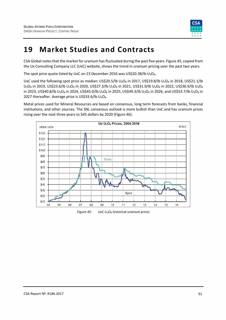
91
GLOBAL ATOMIC FUELS CORPORATION
DASA URANIUM PROJECT, CENTRAL NIGER
CSA-Report Nº: R186.2017
19 Market Studies and Contracts
CSA Global notes that the market for uranium has fluctuated during the past five years. Figure 45, copied from
the Ux Consulting Company LLC (UxC) website, shows the trend in uranium pricing over the past two years.
The spot price quote listed by UxC on 23 December 2016 was US$20.38/lb U3O8.
UxC used the following spot price as median: US$20.5/lb U3O8 in 2017, US$19.8/lb U3O8 in 2018, US$21.1/lb
U3O8 in 2019, US$23.6/lb U3O8 in 2020, US$27.3/lb U3O8 in 2021, US$31.9/lb U3O8 in 2022, US$36.9/lb U3O8
in 2023, US$40.8/lb U3O8 in 2024, US$45.0/lb U3O8 in 2025, US$49.3/lb U3O8 in 2026, and US$53.7/lb U3O8 in
2027 thereafter. Average price is US$33.6/lb U3O8.
Metal prices used for Mineral Resources are based on consensus, long term forecasts from banks, financial
institutions, and other sources. The SNL consensus outlook is more bullish than UxC and has uranium prices
rising over the next three years to $45 dollars by 2020 (Figure 46).
Figure 45: UxC U3O8 historical uranium prices

92
GLOBAL ATOMIC FUELS CORPORATION
DASA URANIUM PROJECT, CENTRAL NIGER
CSA-Report Nº: R186.2017
Figure 46: NL consensus pricing forecast
93
GLOBAL ATOMIC FUELS CORPORATION
DASA URANIUM PROJECT, CENTRAL NIGER
CSA-Report Nº: R186.2017
20 Environmental Studies, Permitting and Social or Community Impact
This section is not applicable to the current report.

94
GLOBAL ATOMIC FUELS CORPORATION
DASA URANIUM PROJECT, CENTRAL NIGER
CSA-Report Nº: R186.2017
21 Capital and Operating Costs
This section is not applicable to the current report.

95
GLOBAL ATOMIC FUELS CORPORATION
DASA URANIUM PROJECT, CENTRAL NIGER
CSA-Report Nº: R186.2017
22 Economic Analysis
This section is not applicable to the current report.
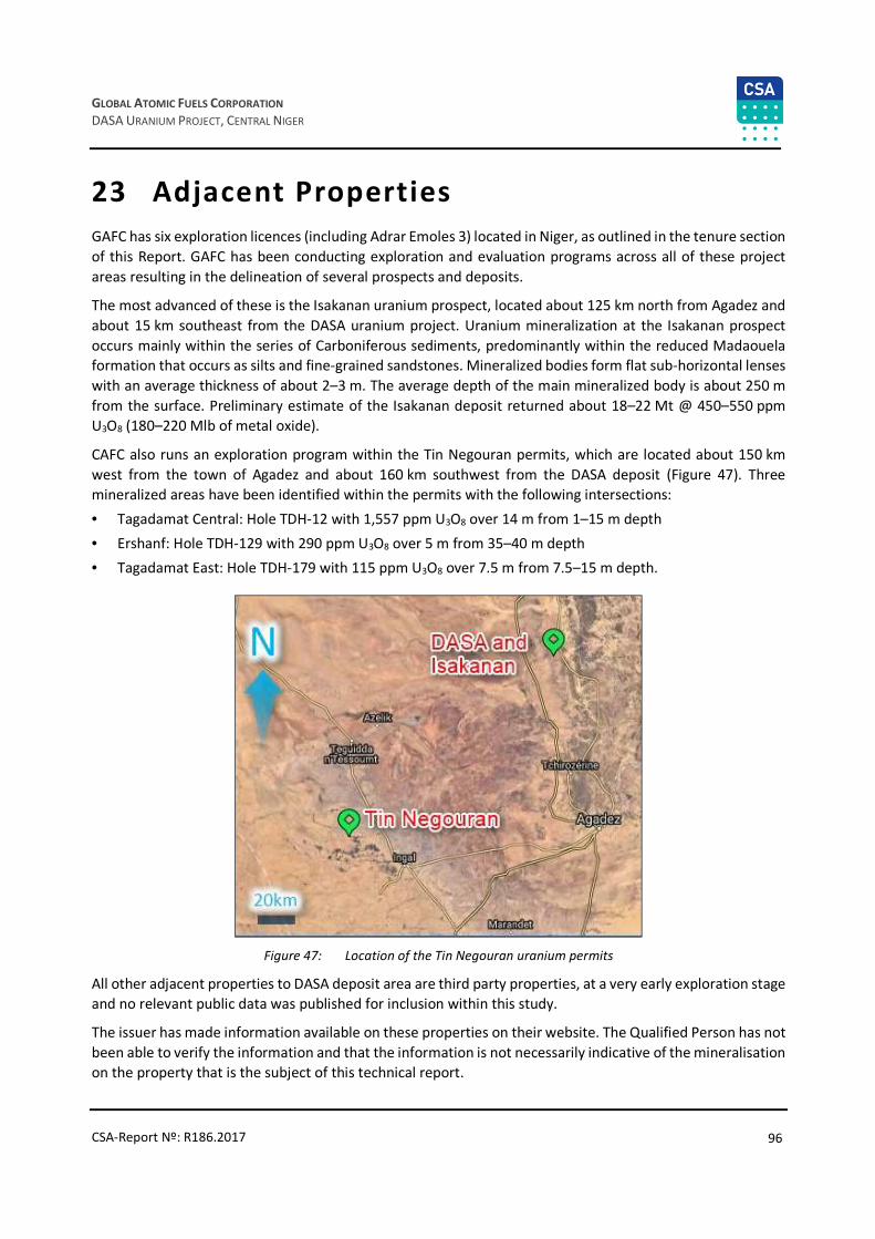
96
GLOBAL ATOMIC FUELS CORPORATION
DASA URANIUM PROJECT, CENTRAL NIGER
CSA-Report Nº: R186.2017
23 Adjacent Properties
GAFC has six exploration licences (including Adrar Emoles 3) located in Niger, as outlined in the tenure section
of this Report. GAFC has been conducting exploration and evaluation programs across all of these project
areas resulting in the delineation of several prospects and deposits.
The most advanced of these is the Isakanan uranium prospect, located about 125 km north from Agadez and
about 15 km southeast from the DASA uranium project. Uranium mineralization at the Isakanan prospect
occurs mainly within the series of Carboniferous sediments, predominantly within the reduced Madaouela formation that occurs as silts and fine-grained sandstones. Mineralized bodies form flat sub-horizontal lenses
with an average thickness of about 2–3 m. The average depth of the main mineralized body is about 250 m
from the surface. Preliminary estimate of the Isakanan deposit returned about 18–22 Mt @ 450–550 ppm
U3O8 (180–220 Mlb of metal oxide).
CAFC also runs an exploration program within the Tin Negouran permits, which are located about 150 km
west from the town of Agadez and about 160 km southwest from the DASA deposit (Figure 47). Three
mineralized areas have been identified within the permits with the following intersections:
• Tagadamat Central: Hole TDH-12 with 1,557 ppm U3O8 over 14 m from 1–15 m depth
• Ershanf: Hole TDH-129 with 290 ppm U3O8 over 5 m from 35–40 m depth
• Tagadamat East: Hole TDH-179 with 115 ppm U3O8 over 7.5 m from 7.5–15 m depth.
Figure 47: Location of the Tin Negouran uranium permits
All other adjacent properties to DASA deposit area are third party properties, at a very early exploration stage
and no relevant public data was published for inclusion within this study.
The issuer has made information available on these properties on their website. The Qualified Person has not
been able to verify the information and that the information is not necessarily indicative of the mineralisation
on the property that is the subject of this technical report.

97
GLOBAL ATOMIC FUELS CORPORATION
DASA URANIUM PROJECT, CENTRAL NIGER
CSA-Report Nº: R186.2017
24 Other Relevant Data and Information
At the time of writing, GAFC is undertaking a conceptual mining study to review the economic potential of
developing a small-scale underground trial mine. The aim of the concept is to develop a decline down to the
mineralisation at the shallowest depths possible in a cash flow positive scenario. The aim being to collect bulk
mineralisation samples for test milling and uranium recovery studies at a scale that would allow the sale of
the uranium. This concept has the dual benefit of completing the underground development required to
support a much larger underground mining scenario in the future should it be required.
The selected scenario will necessarily target higher grade material from within the deposit to make an
economic case for development. However, it will also mean that during trial mining GAFC can complete
further technical work on the Mineral Resource to increase the size and improve the confidence and
classification. Using these data, they could then move the project towards higher confidence feasibility
studies.
The concept study will evaluate a range of production rates from 500 to 2000 tonnes/day and will look to
target material from within the resource with a grade suitable to cover the costs of development. The concept
would involve treating the mined material at a nearby processing facility. This limits the capital expenditure
requirements to those required directly for underground mining, thus keeping such capital costs to a
minimum.

98
GLOBAL ATOMIC FUELS CORPORATION
DASA URANIUM PROJECT, CENTRAL NIGER
CSA-Report Nº: R186.2017
25 Interpretation and Conclusions
This Report was initiated by GAFC for CSA Global to estimate Mineral Resources for the DASA Project located
in Niger. The Report describes previous work by GAFC (and others) and the work done by CSA Global to
estimate Mineral Resources at the DASA Project. The interpretation and modelling work has resulted in CSA
Global estimating a Mineral Resource for the project in the Indicated and Inferred categories. The results of
this Mineral Resource are summarised in Table 23 below.
Table 23: Mineral Resources for the DASA Project (CSA Global)
Category Tonnes (Mt) eU3O8 (ppm) Contained metal (Mlb)
Indicated 3.7 2,608 21.4
Inferred 7.7 2,954 49.8
CSA Global believes this Mineral Resource is a reliable estimate of the mineralization present at the DASA.
The data used as inputs to the model have been collected and compiled at high standard and indicate that
the project is a high quality mineral asset. Additionally, mineralization potential exists within the project along
strike to the north and south, as well as within the graben providing significant upside potential. As such, CSA
Global recommends that additional exploration work be conducted at the project to enlarge the resource and
improve the classification of the current Mineral Resource to a higher classification.
A review of the project risks identified the following:
• Initial data: radioactive equilibrium factor was defined based on comparison of assays with gamma
logging. There is no investigation of radon degassing factor which may influence significantly the gamma activity. Comparison of gamma logging with radium assays in closed cans as well as radium assays in
closed cans with uranium assays allows to define reliably the radiological factors.
• Mineral Resource: The mineral resource model documented herein is sufficiently reliable to support engineering and design studies to evaluate the viability of a mining project at a scoping level followed by
preliminary feasibility level. The project’s economic viability is sensitive to the estimated uranium grade
of the resource and the uranium market price. Infill drilling in critical areas would significantly reduce any
potential risk in the resource estimation.
• Mining: It is expected that part of the deposit will be mined using industry standard open pit mining
techniques utilising modern technology with proven success, with no requirement for untried or untested
technology. deeper parts of the of the deposit could also be mined using underground methods, and
some areas could also be considered for in-situ uranium leaching. However, this has not been assessed in
this Report.
• Processing: Results of the metallurgical testwork show the mineralogy and metallurgy of the DASA
mineralisation is readily amenable to acid leaching with conventional uranium recovery – similar to the
AREVA operation at Arlit, Niger.
• Environmental and social: Were not part of the project scope. However, the deposit is located in an area
with very limited population. The environment is very arid with limited flora and fauna. Additionally, other
similar mining operations are active in the area. These conditions may be favourable for mine
development.
• Economic outcomes: Economic studies were not part of the Project scope.

99
GLOBAL ATOMIC FUELS CORPORATION
DASA URANIUM PROJECT, CENTRAL NIGER
CSA-Report Nº: R186.2017
• Permitting: The Exploration Permit granted to GAFC was renewed two times. The most recent renewal
occurred in 2016, resulting in an area of 121.3 km2 from the initial area of 488.7 km2 granted in 2007.
GAFC needs to apply for the Exploration Permit again within three years.

100
GLOBAL ATOMIC FUELS CORPORATION
DASA URANIUM PROJECT, CENTRAL NIGER
CSA-Report Nº: R186.2017
26 Recommendations
CSA Global recommends the following are completed to support the exploration and evaluation efforts,
estimated budgets for are provided in Table 24:
• Current QAQC procedures should be maintained to ensure high quality data is available for subsequent
Mineral Resource estimates.
• Further exploration and evaluation programs are required to upgrade the confidence of the extent and
quality of mineralization at the deeper parts of the DASA deposit (inside the graben). Key programs
include:
o Additional diamond core drilling to test the morphology of the mineralization within the shear/fault
zones bounding the graben as well as to study the distribution of the uranium disequilibrium factor
at the deposit
o Step-out drilling to the north and south should be considered to enlarge the resources
o Infill drilling will be required within the Inferred and Indicated Resource areas if a higher classification
is sought by GAFC
o Supporting studies such as hydrological, geotechnical and metallurgical should be completed during
drilling programs to inform the Preliminary Economic Assessment (PEA)
o Consider logging the drillholes using a PFN tool to assist in mapping any disequilibrium within the
deposit
o Complete a stratigraphic study within the DASA project area to assess where other targets may exist
and host similar deep mineralisation.
• It is recommended to consider some areas of the deposit for in-situ leaching techniques.
• The project should be subject to PEA to assess the economics and areas that require more detailed study.
Should this be successful more detailed feasibility studies should be considered.
• Some additional investigations are required for definition of radio active equilibrium factor distribution
to upgrade resource categories and understanding of uranium mineralization. CSA Global recommends
assaying for radium in sealed cans and uranium by XRF. Comparison of radium and uranium assays allows
the reliable assessment of the REF; comparison of radium assays and gamma logging allows definition of
the radon degassing factor. This factor may also influence the definition of eU3O8 grades.
• Additional metallurgical tests are recommended to assess the recovery of uranium of the deeper
mineralisation within the Graben structure to better understand the metal recovery for the entire
deposit.
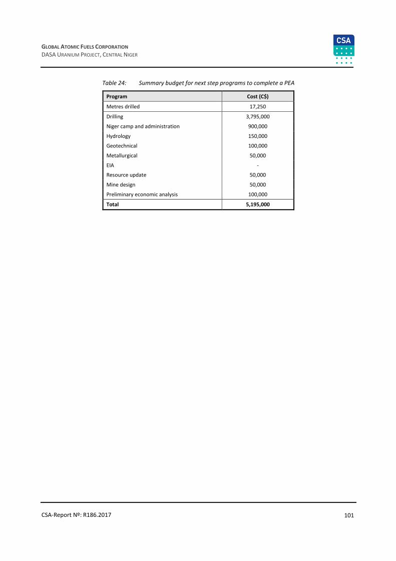
101
GLOBAL ATOMIC FUELS CORPORATION
DASA URANIUM PROJECT, CENTRAL NIGER
CSA-Report Nº: R186.2017
Table 24: Summary budget for next step programs to complete a PEA
Program Cost (C$)
Metres drilled 17,250
Drilling 3,795,000
Niger camp and administration 900,000
Hydrology 150,000
Geotechnical 100,000
Metallurgical 50,000
EIA -
Resource update 50,000
Mine design 50,000
Preliminary economic analysis 100,000
Total 5,195,000

102
GLOBAL ATOMIC FUELS CORPORATION
DASA URANIUM PROJECT, CENTRAL NIGER
CSA-Report Nº: R186.2017
27 References
Activation Lab, 2007. Petrographic study of rocks from a uranium prospect; Internal study for Global Atomic Fuels
Cazoulat, M. 1985. Geologic environment of the uranium deposits in the carboniferous and Jurassic sandstones of the western margin of the Air Mountains in the Republic of Niger; IARE TECDOC-328, p.247-263
Cazoulat, M. 1985. Geologic environment of the uranium deposits in the carboniferous and Jurassic sandstones of the western margin of the Air Mountains in the Republic of Niger, IAEA-TECDOC-328, p 247-263
Gauthier, J.M. 1972. Analyse tectonique du demi-degré carré (Nord) d'Afasto. CEA-GAM
Gauthier, J.M. 1974. Analyse tectonique du demi-degré carré (Nord) d'Afasto. C.E.A. - G.A.M
Gerbaud, O. 2006. Evolution structurale du bassin de Tim Mersoï: Déformations de la couverture sédimentaire, relations avec la localisation des gisements uranifères du secteur d’Arlit (Niger). Thesis, Université de Paris-Sud, U.F.R. Scientifique d’Orsay
Graef, F., Atlas des ressources naturelles et agronomiques du Niger et du Bénin. Universität Hohenheim
Greigert, J., and Pougnet, R. 1967. Essai de description des formations géologiques de la république du Niger. Publication Direction des Mines et de la Géologie, Niger, n°3, 273 p.
Guiraud, R., Boureïma O. and Robert J.-P. 1981. Mise en évidence de déformations traduisant un raccourcissement dans le Mésozoïque de la périphérie de l'Aïr (Niger). Comptes-Rendus Académie des Sciences, Paris, t. 292, série II, p.753-756
Hirlemann, G., Faure, H. 1978. Analyse structurale du secteur Afasto. CEA-GAM
Hirlemann, G., Robert, J.P. 1977. Analyse structurale du secteur Arni. CEA-GAM
Hirlemann, G., Robert, J.P. 1980. Analyse structurale du permis minier Imouraren. CEA-GAM
https://www.uni-hohenheim.de/atlas308/startpages/page2/french/content_fr/conframe_fr.htm
Jean Martin von Siebenthal: DASA Geology and structure, Global internal report, unpublished; 2013
Joulia, F. 1957. Sur l'existence d'un important système de fractures intéressant le Continental intercalaire à l'Ouest de l'Aïr (Niger, A.O.F). Bulletin de la Société Géologique de France, p.137-143
Joulia, F. 1959. "Les séries primaires au N et au NW de l'Aïr (Sahara central). Discordances observées. Bulletin de la Société Géologique de France, p. 192-196
Joulia, F. 1963. Carte géologique de reconnaissance de la bordure sédimentaire occidentale de l'Aïr au 1/500 000. Éditions du BRGM, Orléans, France
Joulia, F., and Obellianne, J.M. 1976. Levers géologiques à l'ouest de l'Aïr. COGEMA, inédit
Konaté, M., Denis, M., Yahaya, M. and Guiraud, M. 2007. Structuration extensive et transtensive au dévono-dinantien du bassin de Tim Mersoï (Bordure occidentale de l'Aïr, Nord Niger). Annales de l’Université de Ouagadougou - Série C, Vol. 005, juin 2007
Lang, J., Yahaya, M., El Hamet, M.O., Besombes, J.-C., and Cazoulat, M. 1991. Dépôts glaciaires du Carbonifère inférieur à l'Ouest de l'Aïr. Geologie Rundschau 80 (3), 611-622
Molebale, I. 2012. U-mineral characterisation and bulk modal analysis of then composite samples from a sandstone hosted uranium deposit, Northern Niger. Mintek, internal report for Global Atomic Fuels
Périmètre In Adrar, Dossier technique, Cogema internal report; 1977
Perimetre Tin Adradar; Dossier Technique, Cogema Internal Report, 1977

103
GLOBAL ATOMIC FUELS CORPORATION
DASA URANIUM PROJECT, CENTRAL NIGER
CSA-Report Nº: R186.2017
Projet Sekiret, Programme des Travaux de la 3eme Campagne 1983-1984, Document 1-7, Association Onarem PNC, Annual technical report, 1984
Projet Sekiret, Programme des Travaux de la 4eme Campagne 1984-1985, Document 1-4, Association Onarem PNC, Annual technical report, 1985
Projet Sekiret, Programme des Travaux de la 5eme Campagne 1985-1986, Document 1-4, Association Onarem PNC, Annual technical report, 1986
Rapport des activités de la champagne de prospection d’uranium, projet Sekiret, Document 1-6, Association Onarem PNC, Annual technical report, 1983
Sempéré, T. 1981. Le contexte sédimentaire du gisement d'uranium d'Arlit (République du Niger). Mémoire Thèse, Ecole Nationale Supérieure des Mines de Paris, 374 pages
Valsardieu, C. 1971. Etude géologique et paléogéographique du Bassin de Tim Mersoï, région d'Agadès (République du Niger). Thèse, Nice, Rapport CEA-R-4115, 518 pages
Wright, L. I., Branchet, M., et Alisso, I. 1993. Notice explicative de la carte géologique du bassin houillier d'Anou Araren / Solomi. Ministère des Mines et de l'Énergie, Niger, 20 pages
Wright, L. 2010. The Field visit and Geological Interpretation of the Adrar Emoles Concessions, Niger. Global Atomic Fuels Corp. internal document
Wright, L. 2012. Re-Evaluation of the Dajy deposits in the light of the tectonic interpretation. Global Atomic Fuels Corp. internal document
Yahaya, M. 1992. Dynamique sédimentaire du Guézouman et des formations viséennes sous-jacentes en liaison avec la tectonique, le volcanisme et le climat. PhD Thesis Université de Bourgogne, 355 pages
Yahaya, M., and Lang, J. 2000. Évolution tectono-sédimentaire de l'Unité d'Akokan au cours du Viséen dans le bassin de Tim Mersoï (région d'Arlit, Niger). Journal of African Earth Science, vol. 31, No. 2, 415-431

104
GLOBAL ATOMIC FUELS CORPORATION
DASA URANIUM PROJECT, CENTRAL NIGER
CSA-Report Nº: R186.2017
28 Dates and Signatures – Certificates of Qualified Persons
CERTIFICATE OF QUALIFIED PERSON – DMITRY PERTEL
I, Dmitry Pertel, Geologist, as an author of this report entitled NI 43-101 Technical Report for the DASA
Uranium Project, Niger, prepared for Global Atomic Fuels Corporation and dated 30 April 2017, do hereby certify that:
1. I am a Principal Geologist with CSA Global Pty Ltd. My office address is Level 2, 3 Ord Street, West Perth, Western Australia 6005.
2. I am a graduate of the Saint Petersburg Mining University in 1986 with a Master’s degree in Geology.
3. I am a Member of Australian Institute of Geoscientists (AIG) and registered as a Professional Geoscientist, Certificate #2248. I have worked as a Geologist for a total of 31 years since my graduation. My relevant experience for the purpose of the Technical Report is:
a. Development and reporting of Mineral Resource models
b. Review and report QA and QC procedures and protocols, site visits and laboratory inspections
c. Principal Geologist on a number of Mineral Resource studies and development of block models in the uranium industry in Africa, Australia and Asia.
4. I have read the definition of 'qualified person' set out in National Instrument 43-101 ('NI 43-101') and certify that by reason of my education, affiliation with a professional association (as defined in NI 43-101) and past relevant work experience, I fulfill the requirements to be a 'qualified person' for the purposes of NI 43-101.
5. I have visited the DASA Project in March-April 2017.
6. I am responsible for all of preparation of Item Numbers: 1 (sub sections: 1, 2, 3, 4), 2, 3, 4, 14, 25 and 26 of the Technical Report.
7. I am independent of the Issuer applying the test set out in Section 1.5 (4) of NI 43-101.
8. I have not been involved in any previous Technical Report on the DASA uranium Project.
9. I have read NI 43-101, and the Technical Report has been prepared in compliance with NI 43-101 and Form 43-101F1.
10. To the best of my knowledge, information, and belief, the Technical Report contains all scientific and technical information that is required to be disclosed to make the technical report not misleading.
Dated this 30 April 2017
Dmitry Pertel
CSA Global Principal Geologist
105
GLOBAL ATOMIC FUELS CORPORATION
DASA URANIUM PROJECT, CENTRAL NIGER
CSA-Report Nº: R186.2017
CERTIFICATE OF QUALIFIED PERSON – MAXIM SEREDKIN
I, Maxim Seredkin, Geologist, as an author of this report entitled NI 43-101 Technical Report for the DASA
Uranium Project, Niger, prepared for Global Atomic Fuels Corporation and dated 30 April 2017, do hereby
certify that:
1. I am a Principal Geologist with CSA Global Pty Ltd. My office address is Level 2, 3 Ord Street, West Perth, Western Australia 6005.
2. I am a professional geologist having graduated with a BSc (Geology), 1997, from the Moscow State University, Russia and a PhD from the Moscow State University, Russia, majoring in petrology and volcanology in 2001.
3. I am a Fellow of Australasian Institute of Mining and Metallurgy (FAusIMM), and Member of the Australian Institute of Geoscientists (MAIG), expert of NAEN. I have worked as a geologist for a total of 19 years since my graduation from university including 11 years at uranium deposits in Kazakhstan, Russia and Africa.
4. I have read the definition of 'qualified person' set out in National Instrument 43-101 ('NI 43-101') and certify that by reason of my education, affiliation with a professional association (as defined in NI 43-101) and past relevant work experience, I fulfill the requirements to be a 'qualified person' for the purposes of NI 43-101.
5. I have not visited the DASA Project.
6. I am responsible for all of preparation of Item Numbers: 1 (sub sections: 2, 3, 4), 4, 5, 6, 7, 8, 9, 10, 11 and 12of the Technical Report.
7. I am independent of the Issuer applying the test set out in Section 1.5 (4) of NI 43-101.
8. I have not been involved in any previous Technical Report on the DASA uranium Project.
9. I have read NI 43-101, and the Technical Report has been prepared in compliance with NI 43-101 and Form 43-101F1.
10. To the best of my knowledge, information, and belief, the Technical Report contains all scientific and technical information that is required to be disclosed to make the technical report not misleading.
Dated this 30 April 2017
Dr Maxim Seredkin
CSA Global Principal Geologist

106
GLOBAL ATOMIC FUELS CORPORATION
DASA URANIUM PROJECT, CENTRAL NIGER
CSA-Report Nº: R186.2017