NFPA Aluminum & Steel Cylinders ACTUATORScdn.norgren.com/pdf/SeriesAandJ_ACT-6-26.pdf · NFPA...
21
ACT-6 ACTUATORS Norgren.com/usa – 303.794.2611 – [email protected] Impact dampening seals Adjustable captive cushion needle Ecology cylinders meet OSHA noise standards Constructed of the finest materials Technical data Medium: Filtered compressed air to 250 PSI Petroleum based hydraulic fluid to 400 PSI* Operating temperature: Series A & J -20°F to 200°F with Viton Seals -20˚F to 400˚F Operating Pressure: 250 PSIG Air, 400 PSIG Hydraulic* non-shock. NOTE: EA and EJ max pressure rating: 150 psi. Bore Sizes: 1-1/2", 2", 2-1/2", 3-1/4", 4", 5", 6", 7", 8", 10"*, 12"* Lubrication: None required Norgren Air Cylinders are rated for “no lube added” service. All internal components are lubricated at time of assembly with a Teflon® based grease. Materials Head and End Caps: (A and EA Series) black anodized aluminum alloy (J and EJ Series) precision machined steel* Tube: A & EA Series 1-1/2" to 12" J & EJ Series 1-1/2" to 2-1/2" Aluminum alloy, clear anodized O.D., hard coat anodized I.D. J & EJ Series 3-1/4" to 12" has steel tube, with hard chrome plated I.D. Piston: A & EA series: machined high- strength aluminum alloy. J & EJ series: steel Piston rod: hard chrome plated steel Rod Bearing: oil impregnated sintered iron Seals: nitrile rod seal, urethane rod wiper, nitrile piston seals, nitrile tube end seals Tie Rods: high-tensile strength steel * J and EJ series only NFPA Aluminum & Steel Cylinders NFPA Series A Aluminum & J Steel Cylinders 1-1/2 to 12 inch bore size Ultra Cushion ® Seals: Advanced design features a unique, one-piece, compound seal of nitrile* captured within a precision machined groove. Linear and radial “float” of the cushion seals eliminates misalignment. Ultra Cushions provide exceptionally fast “out of cushion” stroke reversal. (Head and Cap Cushions are optional.) *Nitrile seals on the 5/8" & 1" rod diameter. For rod sizes 1-3/4" and larger, urethane seals are standard. Adjustable Captive Cushion Needle: A one- piece, precision threaded brass cushion adjustment screw with a threaded steel capture ring. It provides safe and precise cushion adjustment. Wear Ring: Reinforced Teflon ® compounded with polyphenylene sulfide provides supreme wear and excellent bearing support. 5 Rod Seal: Nitrile lip type seal is pressure energized and wear compensating for durability and long life. 6 1 Wiper Seal: Lip-type urethane wiper seal keeps contaminates from getting into cylinder by aggressively wiping foreign materials from the piston rod, enhancing the rod seal life. 3 4 1 2 3 3 5 4 O-Ring Tube Seal: Nitrile is standard. (Viton is optional.) 2 6
Transcript of NFPA Aluminum & Steel Cylinders ACTUATORScdn.norgren.com/pdf/SeriesAandJ_ACT-6-26.pdf · NFPA...

ACT-6
ACTUATORS
Norgren.com/usa – 303.794.2611 – [email protected]
Impact dampening sealsAdjustable captive cushion needleEcology cylinders meet OSHAnoise standardsConstructed of the finest materialsTechnical dataMedium:Filtered compressed air to 250 PSIPetroleum based hydraulic fluid to400 PSI*Operating temperature:Series A & J -20°F to 200°F with Viton Seals -20˚F to 400˚FOperating Pressure:250 PSIG Air, 400 PSIG Hydraulic*non-shock.NOTE: EA and EJ max pressurerating: 150 psi. Bore Sizes: 1-1/2", 2", 2-1/2", 3-1/4", 4", 5", 6", 7", 8", 10"*, 12"*Lubrication:None requiredNorgren Air Cylinders are rated for“no lube added” service. All internalcomponents are lubricated at time ofassembly with a Teflon® basedgrease.Materials Head and End Caps: (A and EA Series)black anodized aluminum alloy(J and EJ Series)precision machined steel*Tube: A & EA Series 1-1/2" to 12"J & EJ Series 1-1/2" to 2-1/2"Aluminum alloy, clear anodized O.D.,hard coat anodized I.D.J & EJ Series 3-1/4" to 12" has steeltube, with hard chrome plated I.D.Piston: A & EA series: machined high-strength aluminum alloy. J & EJ series: steelPiston rod: hard chrome plated steelRod Bearing: oil impregnatedsintered ironSeals: nitrile rod seal, urethane rodwiper, nitrile piston seals, nitrile tubeend sealsTie Rods: high-tensile strength steel* J and EJ series only
NFPA Aluminum & Steel CylindersNFPA Series A Aluminum & J Steel Cylinders1-1/2 to 12 inch bore size
Ultra Cushion® Seals: Advanced designfeatures a unique, one-piece, compound seal ofnitrile* captured within a precision machinedgroove. Linear and radial “float” of the cushionseals eliminates misalignment. Ultra Cushionsprovide exceptionally fast “out of cushion” strokereversal. (Head and Cap Cushions are optional.)*Nitrile seals on the 5/8" & 1" rod diameter. For rod sizes 1-3/4" and larger, urethane seals are standard.
Adjustable Captive Cushion Needle: A one-piece, precision threaded brass cushionadjustment screw with a threaded steel capturering. It provides safe and precise cushionadjustment.
Wear Ring: Reinforced Teflon®
compounded with polyphenylene sulfide providessupreme wear and excellent bearing support.
5
Rod Seal: Nitrile lip type seal is pressureenergized and wear compensating for durabilityand long life.
6
1
Wiper Seal: Lip-type urethane wiper seal keeps contaminates from getting into cylinder by aggressively wiping foreign materials from thepiston rod, enhancing the rod seal life.
3
4
1 2
3
35
4
O-Ring Tube Seal: Nitrile is standard. (Viton isoptional.)
2
6
01 NFPA 4th_01NFPA 06 1/31/11 12:12 PM Page 6
ACT-7
ACTUATORS
Ultra Cushion® Seals: Advanced designfeatures a unique, one-piece, compound seal ofnitrile* captured within a precision machinedgroove. Linear and radial “float” of the cushionseals eliminates misalignment. Ultra Cushionsprovide exceptionally fast “out of cushion” strokereversal. (Head and Cap Cushions are optional.)*Nitrile seals on the 5/8" & 1" rod diameter. For rod sizes 1-3/8" and larger, urethane seals are standard.
O-Ring Tube Seal: Buna is standard. (Viton isoptional.)
Cylinder Tube: High-strength aluminumalloy ideally suited for air service. The tube isclear anodized on the O.D. and hard anodiccoated on the I.D., resulting in a smooth,corrosion and score resistant surface finish.
Tie Rods: High-strength steel maintains uniformcompression on tube end seals.
Piston: Machined solid aluminum alloy, light-weight for low inertia, yet strong. Threaded pistonis installed with high strength threadlockeradhesive then staked to the piston rod.
Adjustable Captive Cushion Needle: A one-piece, precision threaded brass cushionadjustment screw with a threaded steel capturering. It provides safe and precise cushionadjustment.
6
Piston Seals: Long-wearing nitrile seals.
Wear Ring: Reinforced Teflon®
compounded with polyphenylene sulfide providessupreme wear and excellent bearing support.
Standard non-cushioned Series A cylinders arerecommended for applications that require fullbottoming of the piston and where the noise emitted bythe metal-to-metal impact between the piston andcylinder end caps is tolerable. We recommend thatoptional non-adjustable cushions be added for pistonspeeds (moving light tools) ranging from 15 to 30in/sec. For speeds exceeding 30 in/sec, the cylindersshould be equipped with adjustable air cushions.
1112
13
Piston Rod: Hard chrome plated high-tensilesteel, ground and polished.
Rod Bearing: External removable threadedsteel bearing housing (black oxide finish), with anoil-impregnated sintered iron rod bearing.
Rod Seal: Nitrile lip-type seal is pressure energized and wear compensating fordurability and long life.
Head/Cap: Precision machined from alloyaluminum, then anodized for corrosion resistance(black finish).
1
2
3
5
Wiper Seal: Lip-type urethane wiper seal keeps contaminates from getting into cylinder by aggressively wiping foreign materials from thepiston rod, enhancing the rod seal life.
Application InformationSeries A NFPA interchangeable aluminum air cylindersare offered with a variety of accessories, standard andoptional equipment to meet your application needs.
7
8
9
The addition of a Teflon® wear ring to the outerperimeter of the piston provides lubrication to thecylinder for an extended period of time over cylinderswithout a wear ring.
4
10
Series A Cylinders are constructed with the finest materials for each component!
2
1
7
3 6
6
45
89
4
1312
12
1110
9
Norgren.com/usa – 303.794.2611 – [email protected]
01 NFPA 4th_01NFPA 06 1/31/11 12:13 PM Page 7
ACT-8
NFPA Aluminum & Steel Cylinders
ACTUATORS
Norgren.com/usa – 303.794.2611 – [email protected]
12
2 2
3
4
7
1381
11
9
48
10
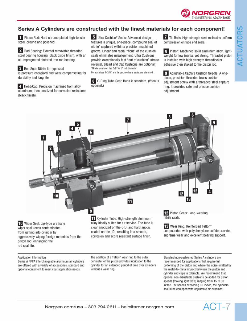
Tie Rods: High-strength steel maintainsuniform compression on tube end seals.
Cylinder Tube: High-strength aluminum alloyideally suited for air service. The tube is clearanodized on the O.D. and hard anodic coated onthe I.D., resulting in a smooth, corrosion andscore resistant surface finish.
Rod Seal: Nitrile lip-type seal is pressureenergized and wear compensating fordurability and long life.
Rod Bearing: External removable steelbearing housing (black oxide finish), with anoil-impregnated sintered iron rod bearing.
11
10
13
Ultra Cushion® Seals: Advanced designfeatures a unique, one-piece, compound seal ofnitrile* captured within a precision machinedgroove. Linear and radial “float” of the cushionseals eliminates misalignment. Ultra Cushionsprovide exceptionally fast “out of cushion” strokereversal. (Head and Cap Cushions are optional.)*Nitrile seals on the 5/8" & 1" rod diameter. For rod sizes 1-3/8" and larger, urethane seals are standard.
Impact Dampening Piston Seals: Our impactdampening piston seals, in conjunction with ouradvanced cushion design, decelerate and reduceend-of-stroke noise.
Piston: Machined solid aluminum alloy, light-weight for low inertia, yet strong. Threadedpiston is installed with high strengththreadlocker adhesive then staked to the pistonrod.
O-Ring Tube Seal: Buna is standard. (Vitonis optional.)
21
3
Adjustable Captive Cushion Needle (notshown): Fine thread allows for safe andprecision adjustment of cushion.
Wiper Seal: Lip-type urethane wiper sealkeeps contaminates from getting into cylinderby aggressively wiping foreign materials fromthe piston rod, enhancing the rod seal life.
Piston Rod: Hard chrome plated high-tensilesteel, ground and polished.
4
7
5
Head/Cap: Precision machined from alloyaluminum, then anodized for corrosionresistance (black finish).
Wear Ring: Reinforced Teflon® compoundedwith polyphenylene sulfide provides supremewear and excellent bearing support.
8
9
6
12
1
Series EA Ecology Cylinders are constructed with the finest materialsfor each component!
6
01 NFPA 4th_01NFPA 06 1/31/11 12:13 PM Page 8

Series J Cylinders are constructed with the finest materials for each component!Ultra Cushion® Seals: Advanced design
features a unique, one-piece, compound seal ofnitrile* captured within a precision machinedgroove. Linear and radial “float” of the cushionseals eliminates misalignment. Ultra Cushionsprovide exceptionally fast “out of cushion” strokereversal. (Head and Cap Cushions are optional.)*Nitrile seals on the 5/8" & 1" rod diameter. For rod sizes 1-3/8" and larger, urethane seals arestandard.
O-Ring Tube Seal: Buna is standard. (Viton isoptional.)
Cylinder Tube: High-strength aluminum alloy1-1/2", 2", 2-1/2" bore anodized on the O.D.and hard coat I.D. Steel cylinder tube hardchrome plated I.D. 3-1/4" to 12" bore.
Tie Rods: High-strength steel maintains uniformcompression on tube end seals.
Piston: Machined solid steel, for highstrength. Threaded piston is installed with highstrength threadlocker adhesive then staked to thepiston rod.
Adjustable Captive Cushion Needle: A one-piece, precision threaded brass cushionadjustment screw with a threaded steel capturering. It provides safe and precise cushionadjustment.
6
Piston Seals: Long-wearing nitrile seals.
Wear Ring: Reinforced Teflon® compoundedwith polyphenylene sulfide provides supremewear and excellent bearing support.
Standard non-cushioned Series J cylinders arerecommended for applications that require fullbottoming of the piston and where the noise emitted bythe metal-to-metal impact between the piston andcylinder end caps is tolerable. We recommend thatoptional non-adjustable cushions be added for pistonspeeds (moving light tools) ranging from 15 to 30in/sec. For speeds exceeding 30 in/sec, the cylindersshould be equipped with adjustable air cushions.
11 12
13
Piston Rod: Hard chrome plated high-tensilesteel, ground and polished.
Rod Bearing: External removable threadedsteel bearing housing (black oxide finish), with anoil-impregnated sintered iron rod bearing.
Rod Seal: Nitrile lip-type seal is pressureenergized and wear compensating for durabilityand long life.
Head/Cap: Precision machined from steel,then black oxide finished 1-1/2" to 2-1/2" bores.Painted black finish on 3-1/4" to 12" bores.
1
2
3
5
Wiper Seal: Lip-type urethane wiper sealkeeps contaminates from getting into cylinderby aggressively wiping foreign materials fromthe piston rod, enhancing the rod seal life.
Application InformationSeries J NFPA interchangeable steel air cylinders areoffered with a variety of accessories, standard andoptional equipment to meet your application needs.
7
8
9
The addition of a Teflon® wear ring to the outerperimeter of the piston provides lubrication to thecylinder for an extended period of time over cylinderswithout a wear ring.
4
10
2
1
7
3 64
58
9
4
1312 1211
10
9
6
ACT-9
NFPA Aluminum & Steel Cylinders
ACTUATORS
Norgren.com/usa – 303.794.2611 – [email protected]
01 NFPA 4th_01NFPA 06 1/31/11 12:13 PM Page 9

ACT-10
NFPA Aluminum & Steel Cylinders
ACTUATORS
Norgren.com/usa – 303.794.2611 – [email protected]
12
2
23
4
67
1381
11
9
48
10
1
Tie Rods: High-strength steel maintainsuniform compression on tube end seals.
Cylinder Tube: High-strength aluminum alloy1-1/2", 2". 2-1/2" bore anodized on the O.D.and hard coat I.D. Steel cylinder tube hardchrome plated I.D. 3-1/4" to 12" bore.
Rod Seal: Nitrile lip-type seal is pressureenergized and wear compensating for durabilityand long life.
Rod Bearing: External removable steelbearing housing (black oxide finish), with an oil-impregnated sintered iron rod bearing.
11
10
13
Piston Rod: Hard chrome plated high-tensilesteel, ground and polished.
Head/Cap: Precision machined from steel,then black oxide finished 1-1/2" to 2-1/2" bores. Painted black finish 3-1/4" to 12" bores.
Wear Ring: Reinforced Teflon®
compounded with polyphenylene sulfide providessupreme wear and excellent bearing support.
7
8
9
12
Series EJ Ecology Cylinders are constructed with the finest materials foreach component!
Ultra Cushion® Seals: Advanced designfeatures a unique, one-piece, compound seal ofnitrile* captured within a precision machinedgroove. Linear and radial “float” of the cushionseals eliminates misalignment. Ultra Cushionsprovide exceptionally fast “out of cushion”stroke reversal. (Head and Cap Cushions areoptional.)*Nitrile seals on the 5/8" & 1" rod diameter. For rod sizes 1-3/8" and larger, urethane seals are standard.
Impact Dampening Piston Seals: Our impactdampening piston seals, in conjunction with ouradvanced cushion design, decelerate and reduceend-of-stroke noise.
Piston: Machined solid steel, for high strength.Threaded piston is installed with high strengththreadlocker adhesive then staked to the pistonrod.
21
3
O-Ring Tube Seal: Buna is standard. (Vitonis optional.)
Adjustable Captive Cushion Needle (notshown): Fine thread allows for safe and precisionadjustment of cushion.\
Wiper Seal: Lip-type urethane wiper sealkeeps contaminates from getting into cylinder byaggressively wiping foreign materials from thepiston rod, enhancing the rod seal life.
5
4
6
01 NFPA 4th_01NFPA 06 1/31/11 12:13 PM Page 10

ACT-11
ACTUATORS
Norgren.com/usa – 303.794.2611 – [email protected]
PSI Cylinder Bore11/2 2 21/2 31/4 4 5 6 7 8 10 12
0 .14 .15 .17 .19 .22 .25 .28 .32 .32 .36 .4020 .10 .10 .12 .14 .16 .18 .20 .22 .22 .24 .2640 .07 .07 .08 .09 .10 .12 .13 .14 .14 .15 .1660 .04 .04 .05 .05 .06 .07 .07 .08 .08 .09 .1080 .02 .02 .02 .02 .03 .03 .03 .04 .04 .04 .04100 0 0 0 0 0 0 0 0 0 0 0
In/Sec Cylinder Bore11/2 2 21/2 31/4 4 5 6 7 8 10 12
6 155.6 275.5 499.8 969.3 1505.4 2603.2 4159.8 5794.2 8067.6 12,242 20,13912 38.4 68.1 123.4 239.7 372.6 644.8 1030.2 1435.8 2000.4 3026 497118 16.7 29.7 53.7 104.6 162.8 282.1 450.6 628.7 876.8 1319.3 2162.124 9.2 16.3 29.4 57.3 89.4 155.2 247.8 346.2 483.6 722 117930 5.6 10.0 18.1 35.4 55.4 96.4 153.9 215.4 301.6 445.5 72436 3.7 6.7 11.9 23.5 37.0 64.5 102.9 144.4 202.7 295.3 476.842 2.6 4.6 8.2 16.3 25.8 45.3 72.2 101.6 143.1 204.8 327.748 1.8 3.2 5.8 11.7 18.6 32.8 52.2 73.8 104.4 146 23154 1.3 2.4 4.2 8.5 13.6 24.2 38.5 54.7 77.9 105.7 164.760 1.0 1.8 3.0 6.2 10.1 18.1 28.7 41.1 58.9 76.9 117.2
Energy Absorption Capacity of the ImpactDampening Seals
Series EA and EJ cylinders have a impactdampening piston seal that accomplishes 80%of the actual load stopping. The air cushionaccounts for only 20%. (A conventional aircushioning cylinder depends 100% on thecompressibility of air to do the stopping.) TheEcology seal absorbs high impact loadsallowing the effect of the air cushion to bereduced by using a larger air cushion bleedorifice. As a result the piston can move at afaster speed for a longer period of time beforethe Ecology seal does the final stopping.
3
Norgren NFPA Ecology Cylinders offer these advantages:
Norgren cylinders are pre-lubriated for non-lubeoperation.
The piston rod is self-lubricated by the oil-impregnated rod bearing during operation.Lubrication between piston and cylinder barrel isderived from the polishing qualities of thereinforced Teflon® wear ring.
The low friction surfaces extend the life of theseals beyond normal expectations.
Series EA and EJ cylinders are NFPAinterchangeable and are available in manydifferent mounting styles.
Operates Quietly to Meet OSHA Specifications.
Series EA and EJ cylinders provide substantialreductions in impact noise, which reduces overallmachine noise and helps meet government regulations.
The summary of sound decibels chart illustratesthe operating sound levels.
The impact dampening qualities of thePiston Seals are guaranteed for ONE FULL YEAR!
1 2Summary of Sound Levels in Decibels
+ Peak sound pressure is given in decibels (dB) re:2 x 10⁵ N/m2.
++End position of mike was 3' on centerline from end ofcylinder; side position of mike was 3' perpendicular tocenterline abeam of end of cylinder.
Effect of Impact Dampening Seals on Total Stroke of Cylinders
*The weight of the cylinder piston has been deducted from the figures shown above. Note: The use of Viton® Seals limits the absorption of the impact dampening seals by 50%.
Energy Absorption Capacity of the Impact Dampening Seals*Usable Pounds Stoppable at the Following Piston SpeedsThis chart features the energy absorption capacity of the impact dampening piston seals with a Non-Adjustable cushions. For higher loads and velocities please refer to the Decel- Air Cushion.
Note: These figures are for new cylinders. The impact dampening seals will take some compression set during operationof the cylinder and the stroke loss will decrease. Also, the pressure at zero stroke loss will decrease to about 80 psi. At pressures above those of zero stroke loss, a slight clicking sound may be produced during impact.To determine the stroke loss for either the head or cap end, divide the value shown by 2.
In/Sec Cylinder Bore11/2 2 21/2 31/4 4 5 6 7 8 10 12
6 279 495 899 1,744 2,709 4,685 7,486 10,429 4,520 22,035 36,25012 68 122 221 430 699 1,159 1,854 2,583 3,800 5,446 8,94718 30 53 95 187 291 507 810 1,130 1,576 2,374 3,89124 16 29 52 102 160 279 444 622 869 1,299 1,41430 10 18 32 63 99 172 275 387 541 801 1,30336 6.7 12 21.6 42 66 116 183 259 363 531 85642 4.7 8.3 14.7 29 46 81 129 181 257 367 58848 3.4 5.7 10.4 21 33 59 93 131 187 262 41554 2.3 4.3 7.6 15.3 24 43 68 97 138 189 29560 1.8 3.2 5.4 11 18 33 52 74 106 138 211
Energy absorption capacity of impact dampening piston seals w/ adjustable cushion.
Piston and rod assembly for1-1/2" thru 5" bore cylinderswith 1/2" to 2" stroke
PSI Air Sound Cylinder ModelPressure J133B3 EJ155B3 J1133A3 EJ1155A3 A133B3 EA155B3 A1133A3 EA1155A3Level+ 5" x 6" 5" x 6" 2" x 6" 2" x 6" 5" x 6" 5" x 6" 2" x 6" 2" x 6"
95 End++ 108 73 110 74 108 73 110 74PSI+ Side++ 112 84 110 81 112 84 110 81
50 End++ 108 73 113 74 108 73 113 74PSI+ Side++ 113 85 110 81 113 85 110 81
Note: At 5 feet, cylinder sound levels would be less by 9 dB fromside figure and 13 dB from end figure. The total noise emitted willdepend on the structure to which the cylinder is attached. If it ismounted on a thin flat plate of considerable area, the noise willbe increased by a sounding board effect.
01 NFPA 4th_01NFPA 06 1/31/11 12:13 PM Page 11
ACT-12
NFPA Aluminum & Steel Cylinders
ACTUATORS
Norgren.com/usa – 303.794.2611 – [email protected]
Operating Temperatures:Series A & J -20°F to 200°F
(-29°C to 107°C)with Viton Seals -20˚F to 400˚F
(-29˚C to 204˚C)
Operating Pressure:250 PSIG Air (17.2 Bar)400 PSIG Hydraulic (27.6 Bar)Bore Sizes: 1-1/2", 2", 2-1/2", 3-1/4", 4", 5", 6", 7", 8", 10", 12"
Supply:Filtered compressed air to 250 PSI Petroleumbased hydraulic fluid to 400 PSI
Side Loading:Cylinders are specifically designed to push andpull. Side loading (misalignment) of the piston rod should be avoided to ensuremaximum operating performance and life.
Care should be taken during installation to properly align the load to be moved with thecenter line of the cylinder. The use of a rod alignment coupler is stronglyrecommended whenever possible.
Lubrication:None requiredNorgren Air Cylinders are rated for “no lubeadded” service. All internal components arelubricated at time of assembly with a Teflon®
based grease.
Materials:Head and End Caps: precision
machined steelTube: 6063-T832 aluminum, clear
anodized O.D., hard coat anodized I.D.Rod: hard chrome plated steelPiston: machined high-strength
aluminum alloyRod Bearing: oil impregnated sintered ironSeals: nitrile rod seal, urethane rod wiper,
nitrile piston seals, nitrile tube end sealsTie Rods: high-tensile strength steel
Air Cylinder Selection:The proper application and selection of an aircylinder requires full consideration of thefollowing: the fluid medium, operating pressures,mounting style, length of stroke, type of rodconnection to the load, thrust or mounting tensionon the rod, mounting attitude, speed of the strokeand how the load motion will be stopped.
The data that follows provides the necessaryinformation in the evaluation of
an average application and will help you inselecting the proper cylinder model and size foryour particular application.
Note: 1-1/2", 2", 2-1/2", 3-1/4", 4" and 5" borecylinders with 1/2" to 2" strokes will be furnishedwith a short head cushion sleeve and short capcushion spear. Only available on 5/8" and 1" rods.
The above specification applies to Series A and Jcylinders with optional non-adjustable oradjustable cushions.
Series A & J Fixed Cushions
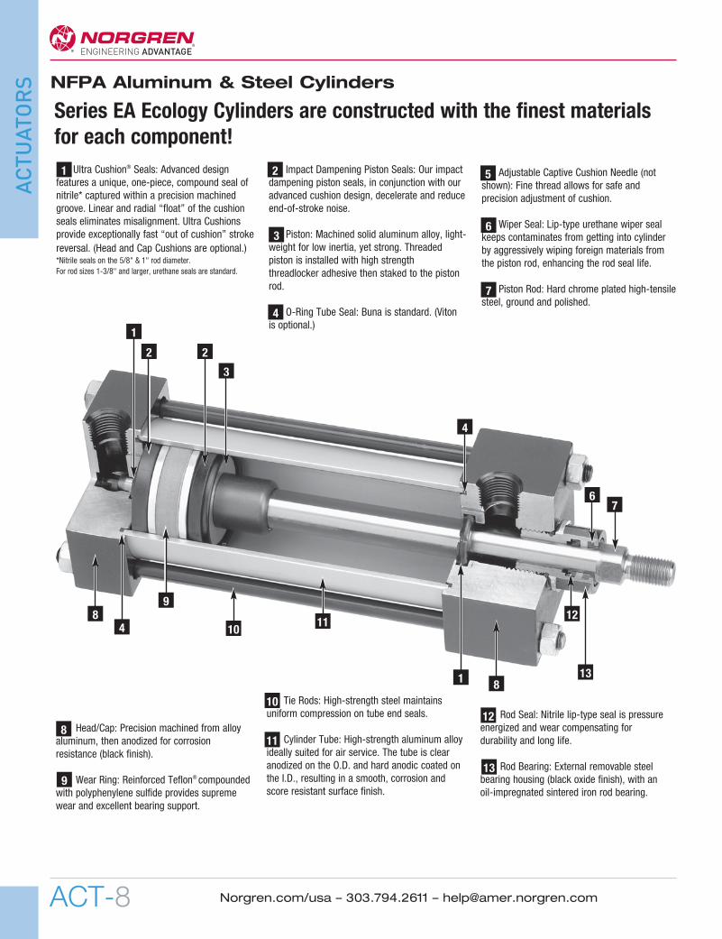
On the reverse stroke the EJ seal releases its compressiveenergy to propel the piston away from the end caps,producing an immediate breakaway.
As the piston continues its travel to the point of impact with theend caps, the compressive qualities of the EJ seal provide thefinal decelerating force. This action compresses the EJ seal andabsorbs the remaining kinetic shock vibration and noisecreated by the impact.
As the cushion spear enters the cushion cavity, the exhaustport becomes sealed off creating an air brake. This providesthe initial deceleration in piston speed. The oversized aircushion bleed orifice permits the cushion pressure to exhaustwith minimal restriction. This allows the piston to movequickly and smoothly through the cushion length.
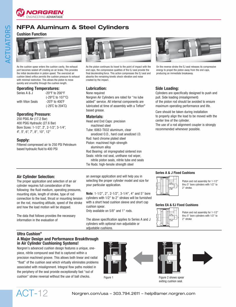
A Major Design and Performance Breakthroughin Air Cylinder Cushioning Systems!Norgren’s advanced cushion design features a unique, one-piece, nitrile compound seal that is captured within aprecision machined groove. This allows both linear and radial“float” of the cushion seal which virtually eliminates problemsassociated with misalignment. Integral flow paths molded inthe periphery of the seal provide exceptionally fast “out ofcushion” stroke reversal without the use of ball checks.
Ultra Cushion®
Figure 1 Figure 2 shows spearexiting cushion seal.
Cushion Function
Piston and rod assembly for 1-1/2"thru 5" bore cylinders with 1/2" to2" stroke
Piston and rod assembly for 1-1/2"thru 5" bore cylinders with 1/2" to2" stroke.
Series EA & EJ Fixed Cushions
01 NFPA 4th_01NFPA 06 1/31/11 12:13 PM Page 12

ACT-13
NFPA Aluminum & Steel Cylinders
ACTUATORS
Norgren.com/usa – 303.794.2611 – [email protected]
Cylinders with Weight attached Cushion Efficiency Cushioning Bounce CyclesCushions to Piston Rod (lbs) (G’s* Created) Time (Ms) During Cushioning
Norgren EcologyAdjustable 54 5.25 40.00 3.25
Norgren EcologyNon-Adjustable 54 12.00 28.75 2.75
Competitor AAdjustable 54 11.50 92.50 6.75
Competitor BAdjustable 54 8.00 77.50 5.25
Competitor CAdjustable 54 6.50 67.50 6.25
Cylinders with Weight attached Cushion Efficiency Cushioning Bounce CyclesCushions to Piston Rod (lbs) (G’s* Created) Time (Ms) During Cushioning
Norgren EcologyAdjustable 8.5 14.50 25.00 1.00
Norgren EcologyNon-Adjustable 8.5 17.50 26.25 1.75
Competitor AAdjustable 8.5 48.00 107.50 7.25
Competitor BAdjustable 8.5 32.75 102.50 6.50
Competitor CAdjustable 8.5 50.50 81.25 9.25
2" Bore Cap End Cushion TestAverage deceleration force = 10 G'sTime consumed during cushioning = 0.020 sec.Number of bounces: 1/2 Pneumatic – 0 Metallic
*Measured in G’s of deceleration force created. All cylinders tested were NFPA types, frontflange mounting, 6" stroke with standard diameter piston rods.
Velocity: 1 div.= 20 in/sec.14.5 lbs. addedto rod
Velocity: 1 div.= 20 in/sec.14.5 lbs. addedto rod
Velocity: 1 div.= 20 in/sec.2.5 lbs. addedto rod
Tests by the Milwaukee School of Engineering confirm Ecology Cylinder Cushions are more efficient, faster acting and bounceless!
2" Bore Cylinder Tests ResultsFigures shown are average and not the result of each individual test. Piston velocity wasregulated at 45 in/sec.
COMPETITIVE CYLINDERSwith Adjustable Cushions
Velocity: 1 div.= 20 in/sec.14.5 lbs. added to rod
Velocity: 1 div.= 20 in/sec.14.5 lbs. addedto rod
Acceleration: 1div. = 10 G’sX Axis: 1 div. =.03 seconds
Acceleration: 1div. = 10 G’sX Axis: 1 div. =.03 seconds
Acceleration: 1 div. = 10 G’sX Axis: 1 div. =.02 seconds
Acceleration: 1div. = 10 G’sX Axis: 1 div. =.03 seconds
Velocity: 1 div.= 20 in/sec.2.5 lbs. added to rod
Acceleration: 1div. = 10 G’sX Axis: 1 div. =.03 seconds
NORGREN ECOLOGY CYLINDERSwith Adjustable Cushions
NORGREN ECOLOGY CYLINDERSwith Non-Adjustable Cushions2" Bore Rod End Cushion TestAverage deceleration force = 15 G'sTime consumed during cushioning = 0.030 sec.Number of bounces: 1 Pneumatic – 1 Metallic
2" Bore Cap End Cushion TestAverage deceleration force = 60 G'sTime consumed during cushioning = 0.120 sec.Number of bounces: 3 Pneumatic – 4 Metallic
2" Bore Rod End Cushion TestAverage deceleration force = 78 G'sTime consumed during cushioning = 0.120 sec.Number of bounces: 2 Pneumatic – 4 Metallic
2" Bore Rod End Cushion TestAverage deceleration force = 20 G'sTime consumed during cushioning = 0.015 sec.Number of bounces: 1/2 Pneumatic – 0 Metallic
2" Bore Cap End Cushion TestAverage deceleration force = 17.5 G'sTime consumed during cushioning = 0.025 sec.Number of bounces: 1 Pneumatic – 1 Metallic
*Measured in G’s of deceleration force created. All cylinders tested were NFPA types, frontflange mounting, 6" stroke with standard diameter piston rods.
4" Bore Cylinder Tests ResultsFigures shown are average and not the result of each individual test. Piston velocity wasregulated at 25 in/sec.
Acceleration: 1div. = 10 G’sX Axis: 1 div. =.03 seconds
01 NFPA 4th_01NFPA 06 1/31/11 12:13 PM Page 13

ACT-14
NFPA Aluminum & Steel Cylinders
ACTUATORS
Norgren.com/usa – 303.794.2611 – [email protected]
Explanation of Decel-Air Cushion:Norgren’s Decel Cushioned cylinder was designed for applicationswhere high velocity, low mass, material transfer or machinefunction is required, and where the kinetic energy to be absorbedduring cushioning exceeds the parameters of our standard SeriesEA or EJ air cylinders equipped with non-adjustable or adjustablecushions. Decel cushions employ longer-than-standard aircushions to assist our Impact Dampening Piston Seal.
Why does our Decel-Air Cushion work?The extra cushion length of the Decel cushioned cylinder providesan additional deceleration capability to slow the cylinder’s movingmass to a point where the positive cushioning effect of our ImpactDampening Piston Seals can perform the final cushioning.
Norgren’s Decel-Air Cushioned Cylinders Versus
Cylinder Mounted Shock AbsorbersThe first extensive evaluation of pneumatic cylinder cushionperformance was undertaken by the Mechanical EngineeringDepartment of The Ohio State University. The test was conductedon 2-1/2" bore, 12" stroke.The OSU tests found the Decel Cushioned cylinders absorbedalmost three times as much kinetic energy with a lower level ofpeak cushion as a standard Ecology seal configured cylinder.
Because air is compressible and is exhausted out of the cylindereach cycle, the internal heat buildup is minimized. The “MaximumInch Pounds Per Hour” rating which is essential in determiningthe effectiveness of shock absorber performance is not needed tojudge Decel cushion performance.
The test indicated that Norgren Decel-Air Cushioned cylinderscould prove to be superior to a hydralic shock absorber assistedcylinder for high cycle, high velocity applications with light tomoderate loading (precisely the area where most severe cylinderapplications exist). The cycle rates and the cushioning times of theDecel-Air Cushioned cylinders and the hydraulic shock absorberassisted cylinders were comparable.*
Decel-Air Cushioned cylinders are also less costly than shockabsorber mounted cylinders and are self-contained units.
*For comparative evaluation, a well-known hydraulic shockabsorber was chosen. The OSU tests showed a smooth shock-absorbing operation was achieved at very low velocities using theshock absorbers, but at comparable Decel Cushion cylindervelocities, a high mechanical impact took place on the shockabsorber mounted cylinder.
Potential Decel-Air Cushion Applications1. Conveyors & Material Handling Equipment2. Transfer Machines & Shuttle Tables3. Packaging Machinery4. Foundry Equipment5. Automatic Gate Opening & Closing
Decel-Air Cushioned CylinderEliminates the need for shock absorbers on air cylinder applications.
Ultra Cushion Seals are made of nitrile* captured withina precision machined groove. The seal’s linear andradial “float” eliminates misalignment and providesexceptionally fast “out of cushion” stroke reversal.*Nitrile seals on the 5/8" and 1" rod diameter. For rod sizes 1-3/8" and larger urethane seals are standard.
Extra cushion sleeve and studlength for longer deceleration
Decel-Air Cushion Spacer Blockallows for extra cushion lengthand longer deceleration
Impact Dampening“Ecology” Piston Sealsabsorb final impact andprovide end of strokecushioning assistance.
Adjustable Captive CushionNeedle is a one-piece,precision threaded brasscushion adjustment screwwith a threaded steel capturering. It provides safe andprecise cushion adjustment
01 NFPA 4th_01NFPA 06 1/31/11 12:13 PM Page 14
ACT-15
NFPA Aluminum & Steel Cylinders
ACTUATORS
Norgren.com/usa – 303.794.2611 – [email protected]
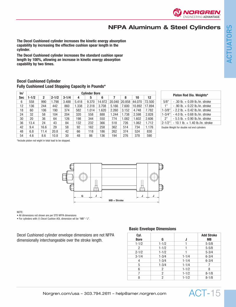
In/ Cylinder BoreSec 1-1/2 2 2-1/2 3-1/4 4 5 6 7 8 10 126 558 990 1.798 3.488 5.418 9.370 14.972 20.040 20.858 44.070 72.50012 136 244 442 860 1.338 2.318 3.708 5.166 7.600 10.892 17.89418 60 106 190 374 582 1.014 1.620 2.260 3.152 4.748 7.78224 32 58 104 204 320 558 888 1.244 1.738 2.598 2.82830 20 36 64 126 198 344 550 774 1.082 1.602 2.60636 13.4 24 43 84 132 232 366 518 726 1.062 1.71242 9.4 16.6 29 58 92 162 258 362 514 734 1.17648 6.8 11.4 20.8 42 66 118 186 262 374 524 83054 4.6 8.6 10.8 30 48 86 136 194 276 378 590
Decel Cushioned CylinderFully Cushioned Load Stopping Capacity in Pounds*
*Include piston rod wight in total load to be stopped.
NOTE:• All dimensions not shown are per STD NFPA dimensions• For cylinders with (1) Decel Cushion AOL dimension wil be “MB”-“J”.
Piston Rod Dia. Weights*
5/8" - .30 lb. + 0.09 lb./in. stroke1" - .90 lb. + 0.22 lb./in. stroke
1-3/8" - 2.2 lb. + 0.42 lb./in. stroke1-3/4" - 4.0 lb. + 0.68 lb./in. stroke2" - 5.5 lb. + 0.90 lb./in. stroke
2-1/2" - 10.1 lb. + 1.40 lb./in. strokeDouble Weight for double rod end cylinders
The Decel Cushioned cylinder increases the kinetic energy absorptioncapability by increasing the effective cushion spear length in thecylinder.The Decel Cushioned cylinder increases the standard cushion spearlength by 100%, allowing an increase in kinetic energy absorptioncapability by two times.
G J J J
MB + Stroke
Decel Cushioned cylinder envelope dimensions are not NFPAdimensionally interchangeable over the stroke length.
Cyl. Add StrokeBore G J MB1-1/2 1-1/2 1 5-5/82 1-1/2 1 5-5/8
2-1/2 1-1/2 1 5-3/43-1/4 1-3/4 1-1/4 6-3/44 1-3/4 1-1/4 6-3/45 1-3/4 1-1/4 76 2 1-1/2 87 2 1-1/2 8-1/88 2 1-1/2 8-1/8
Basic Envelope Dimensions
01 NFPA 4th_01NFPA 06 1/31/11 12:13 PM Page 15

ACT-16
NFPA Aluminum & Steel Cylinders
ACTUATORS
Norgren.com/usa – 303.794.2611 – [email protected]
Port and CushionAdjustment Positions (As viewed from rod end: Portstandard position 1, CushionAdjustment standard position 2.)NOTE: A Port and a Cushion Adjustmentcannot be in the same position.
1
3
4 2
Cylinder Order Information
EJ 01 7 7 A 1 - HR–L(14)–MS–P(1/4) V - 2" x 6"
SeriesSeries A Cylinder (Aluminum) ASeries A Double Rod End Cylinder DASeries EA Cylinder EASeries EA Double Rod End Cylinder EDASeries J Cylinder (Steel) JSeries J Double Rod End Cylinder DJSeries EJ Cylinder EJSeries EJ Double Rod End Cylinder EDJ
Mounting OptionsSide Tapped (MS4) 01Head Rectangular Flange (MF1) 03Head Square (ME3) – 7" & 8" Bores 03Cap Rectangular Flange (MF2) 04Cap Square (ME4) – 7" & 8" Bores 04Basic Cylinder No Mounting (MX0 05Both Ends (4) Tie Rods Ext. (MX1) 06Both Ends (2) Tie Rods Ext. (MX4) 6BCap Tie Rods Ext. (MX2) 6CHead Tie Rods Ext. (MX3) 6RRemovable Head Trunnion (MT1) - A & EA 7RHead Trunnion (MT1) - J & EJ 07Removable Cap Trunnion (MT2) - A & EA 8RCap Trunnion (MT2) - J & EJ 08Side Lugs (MS2) 09Center Trunnion (MT4) 10Side End Angles (MS1) 11Cap Fixed Clevis (MP1) 12Side End Lugs (MS7) 15Sleeve Nut Construction (Universal) 16Head Square Flange (MF5) 20Cap Square Flange (MF6) 21Detachable Cap Clevis (MP2) 22Cap Fixed Eye (MP3) 32Detachable Cap Eye (MP4) 42Spherical Bearing 52Base Bar (Not NFPA A & EA Only) 60
Additional Options – order alphabetically Case Hardened (50 Rc) HRPort Location position 1 standard: L(Head Cap)(specify position 1 thru 4 for head and/or cap) L(_ _)Rod Lock (passive) LELow Friction LFStroke Adjustment AMetal Rod Scraper MSCushion Adjust Screw Location position 2 standard: N(Head Cap) (specify position 1 thru 4 for head and/or cap) N(_ _)Non-Standard Port Sizes: [specify port size for P(_H)head only, P(_C) cap only, or P(_) both head & cap] *P(_)Magnetic Piston – includes aluminum tube option - J & EJ PSRod Stud RSRod Extensions (specify length of additional rod extension) RXStainless Steel tie-rods S303 Stainless Steel (Hard Chrome Plated) SSStainless Steel bushing SBStop Tube (Rod End) (specify stop tube length) ST(_R)Special Rod Threads (specify rod thread) TThread Extensions (specify length of thread extension) TXViton® Seals V
Cushion in Head None 3Non-Adjustable Cushion †5Adjustable Cushion (Position 2) 7Decel Cushion 9
Bore and Stroke (write out )
† Standard with EA & EJ
Piston Rod Threads Type Dim refSmall Male (Solid) (std) 1 KKIntermediate Thread Male (Solid) 2 CCFemale 3 KKFull Thread Male (Solid) 6 FFPlain Rod End 7 –
Cushion in Cap None 3Non-Adjustable Cushion †5Adjustable Cushion (Position 2) 7Decel Cushion 9
† Standard with EA & EJ
Notes+ Head cushion not availale on these bore and piston rodcombinations.Additional rod sizes available upon request.Dimensions for thread sizes available on following pages.
* 1-1/2", 2", 2-1/2" bore cylinders have 3/8" NPT Standard, 1/2" NPT oversize. 3-1/4", 4", 5" bore cylinders have 1/2" NPT Standard, 3/4" NPT oversize.
Cyl rod rod dia.bore ltr. (mm)1-1/2 A 5/8
B+ 1
2 A 5/8B 1C+ 1-3/8A 5/8
2-1/2 B 1C 1-3/8D+ 1-3/4B 1
3-1/4 C 1-3/8D 1-3/4E 2B 1C 1-3/8
4 D 1-3/4E 2F 2-1/2B 1C 1-3/8
5 D 1-3/4E 2F 2-1/2
Cyl rod rod dia.bore ltr. (mm)
C 1-3/8
6 D 1-3/4E 2F 2-1/2C 1-3/8
7 D 1-3/4E 2F 2-1/2C 1-3/8
8 D 1-3/4E 2F 2-1/2D 1-3/4
10 E 2F 2-1/2
12 E 2F 2-1/2
01 NFPA 4th_01NFPA 06 1/31/11 12:13 PM Page 16

ACT-17
ACTUATORS
Norgren.com/usa – 303.794.2611 – [email protected]
Option DescriptionCodeA(–) Stroke adjustment single piston (specify adjustment length)AA(–) Stroke adjustment double piston (specify adjustment length)AN Acorn tie rod nuts (stainless steel)AP Air/Oil piston (piston supplied with O-ring hooded U-cup on cap end for air/oil operation)BL Removable piston rod stud (installed with removable adhesive sealant)EN** Electroless nickel plated cylinderEV(– –) Pneulectric stroke signal valve(s): EV(Head Cap) (specify position)FG Black fiberglass cylinder tubeH Piston rod seals O-ring loaded U-cups – (A & J Only)HR Case hardened piston rodL(– –) Non-standard port location position 1 standard: L (Head Cap) (specify position 1 thru 4 for head and/or cap)LD Rodlock with manual releaseLE RodlockLF Low friction cylinder (Nitrile compounded with Teflon® rod and piston seals) (Not available with Ecology series)MS Metal scraperN(– –) Cushion adjust screw location position 2 standard:N(Head Cap) (specify position 1 thru 4 for head and/or cap)P(–) Non-standard port sizes – [specify port size for P(–H) head only, P(–C) cap only, or P(–) both head & cap]PP Seals in cylinder O-ring loaded U-cups (rod and piston seals) – (A & J Only)PN Pinned piston and rod assemblyPS Magnetic piston modificationRS Studded male piston rod endRX(–) Piston rod extension over standard (specify additional “C” length)S 303/304 Stainless steel tie rods & nutsSB Stainless steel rod bushing nutSC† Single acting spring extend cap end of cylinderSL Steel cylinder tubingSR† Single acting spring retract rod end of cylinder SS 303 Stainless steel piston rodST(–C) Stop tube on cap end (C) of cylinder: ST (stop tube length C)ST(–R) Stop tube on rod end (R) of cylinder: ST (stop tube length R)SV(– –) Stroke signal valve(s): SV (head cap)T(–) Non-standard piston rod thread (specify thread)TF(–) Piston rod thread depth over standard (Female) (specify additional “A” length)TS Stainless cylinder tubingTX(–) Piston rod thread extension over standard (Male) (specify additional “A” length)UB* Head and cap bumpers (Adds 1/4" per bumper to overall length)UC* Cap bumper (Adds 1/4" per bumper to overall length)UH* Head bumper (Adds 1/4" per bumper to overall length)V Viton® seals in cylinderXI(–) Type #10 trunnion set dimension (MT4 model only) (customer must specify length)
Consult Factory for These Options:
†Standard available for 11/2", 2", 2-1/2" bores, 12" max stroke. (Stroke length doubles – 24" max); 12 lbs. force preload, 30 lbs. force compressed. Cushions not available on spring end. For other spring forces, bore sizes or longer strokes, consult factory. *UA Unit Air Assembly** When ordering “EN” option specify S, SS, TS, and SB options.
Option Code DescriptionAS Airsaver stroke adjustmentBB Cylinders mounted back to backCT Close tolerance on cylinder strokeLA Low friction cylinder (Pak-LapTM style seals)NI Nituff® coated cylinderNS No silicone used in cylinder assemblyOE Zero stroke/pneulectric stroke signal valve(s)OV Zero stroke/stroke signal valve(s)RB Rod boot over piston rodTE Nituff® coated cylinder tubingTK Thrust key plate mounting – [01 (MS4), 09 (MS2), and 15 (MS7)VM Valve mounting only
A, EA, J, and EJ Standard and special cylinder options
NFPA Aluminum & Steel CylindersNFPA Series A Aluminum & J Steel Cylinders
1-1/2 to 12 inch bore size
01 NFPA 4th_01NFPA 06 1/31/11 12:13 PM Page 17

ACT-18
NFPA Aluminum & Steel Cylinders
ACTUATORS
Norgren.com/usa – 303.794.2611 – [email protected]
Bore 1-1/2" 2" 2-1/2" 3-1/4" 4" 5" 6" 7" 8" 10" 12"ND .375 .375 .500 .750 .750 .938 1.125 1.125 1.125 1.500 1.500NT 1/4 – 20 5/16 – 18 3/8 – 16 1/2 – 13 1/2 – 13 5/8 – 11 3/4 – 10 3/4 – 10 3/4 – 10 1 – 8 1 – 8SN 2.250 2.250 2.375 2.625 2.625 2.875 3.125 3.250 3.250 4.125 4.625TN .625 .875 1.250 1.500 2.063 2.688 3.250 3.500 4.500 5.500 7.250XT Std. 1.938 1.938 1.938 2.438 2.438 2.438 2.813 2.813 2.813 3.125 3.250
O.S. 2.313 2.313 2.313 2.688 2.688 2.688 3.063 3.063 3.063 3.250 3.500
A
CVF
G
ZB + Stroke
LB + StrokeJ
K
P + StrokeY
øB Bushing
øMMKKThds
D(Flats)
EE NPT (2)
RE Sq.
A
ø B
øMM
A
øMM
ø BKK Thds.
KKThds.A Deep
ø B
øMM
A
ø B
øMM
ø B
øMM
Type 2 Studded(Intermediate Thread
Male Optional)
V
Type 3 Female(Optional)
Type 2 Solid(Intermediate Thread
Male Optional)
Type 6 Solid(Full Thread
Male Optional)
DAcrossFlats
A
øMM
ø BKK Thds.
Type 1 Studded (Studded Male Optional)
Type 1 Solid (Small Male)
CVF
CVF
CVF
CVF
CVF
A
CVF
CCThds.
CCThds.
FFThds.
Bore 1-1/2" 2" 2-1/2" 3-1/4" 4" 5" 6" 7" 8" 10" 12"ø Rod Std. 5/8" 5/8" 5/8" 1" 1" 1" 1-3/8" 1-3/8" 1-3/8" 1-3/4" 2"MM O.S. 1" 1" 1" 1-3/8" 1-3/8" 1-3/8" 1-3/4" 1-3/4" 1-3/4" 2" 2-1/2"A Std. .750 .750 .750 1.125 1.125 1.125 1.625 1.625 1.625 2.000 2.250
O.S. 1.125 1.125 1.125 1.625 1.625 1.625 2.000 2.000 2.000 2.250 3.000B +.000 Std. 1.124 1.124 1.124 1.499 1.499 1.499 1.999 1.999 1.999 2.374 2.624
-.002 O.S. 1.499 1.499 1.499 1.999 1.999 1.999 2.374 2.374 2.374 2.624 3.124C Std. .375 .375 .375 .500 .500 .500 .625 .625 .625 .750 .875
O.S. .500 .500 .500 .625 .625 .625 .750 .750 .750 .875 1.000CC Std. 1/2 – 20 1/2 – 20 1/2 – 20 7/8 – 14 7/8 – 14 7/8 – 14 1-1/4-12 1-1/4-12 1-1/4-12 1-1/2-12 1-3/4-12
O.S. 7/8 – 14 7/8 – 14 7/8 – 14 1-1/4-12 1-1/4-12 1-1/4-12 1-1/2-12 1-1/2-12 1-1/2-12 1-3/4-12 2-1/4-12D Std. .500 .500 .500 .813 .813 .813 1.125 1.125 1.125 1.500 1.688
O.S. .813 .813 .813 1.125 1.125 1.125 1.500 1.500 1.500 1.688 2.063E 2.000 2.500 3.000 3.750 4.500 5.500 6.500 7.500 8.500 10.625 12.750EE .375 .375 .375 .500 .500 .500 .750 .750 .750 1.000 1.000FF Std. 5/8-18 5/8-18 5/8-18 1 – 14 1 – 14 1 – 14 1-3/8-12 1-3/8-12 1-3/8-12 1-3/4-12 2-12
O.S. 1 – 14 1 – 14 1 – 14 1-3/8-12 1-3/8-12 1-3/8-12 1-3/4-12 1-3/4-12 1-3/4-12 2-12 2-1/2-12G 1.500 1.500 1.500 1.750 1.750 1.750 2.000 2.000 2.000 2.250 2.250J 1.000 1.000 1.000 1.250 1.250 1.250 1.500 1.500 1.500 2.000 2.000K .250 .313 .313 .375 .375 .438 .438 .563 .563 .688 .688KK Std. 7/16 – 20 7/16 – 20 7/16 – 20 3/4 – 16 3/4 – 16 3/4 – 16 1 – 14 1 – 14 1 – 14 1-1/4 – 12 1-1/2 – 12
O.S. 3/4 – 16 3/4 – 16 3/4 – 16 1 – 14 1 – 14 1 – 14 1-1/4 – 12 1-1/4 – 12 1-1/4 – 12 1-1/2 – 12 1-7/8 – 12LB 3.625 3.625 3.750 4.250 4.250 4.500 5.000 5.125 5.125 6.375 6.875P 2.340 2.340 2.470 2.690 2.690 2.940 3.125 3.250 3.250 4.125 4.625R 1.428 1.838 2.192 2.758 3.323 4.101 4.87 5.730 6.442 8.004 9.4069VF Std. .625 .625 .625 .875 .875 .875 1.000 1.000 1.000 1.125 1.125
O.S. .875 .875 .875 1.000 1.000 1.000 1.125 1.125 1.125 1.125 1.250Y Std. 1.840 1.840 1.840 2.380 2.380 2.380 2.813 2.813 2.813 3.125 3.250
O.S. 2.220 2.220 2.220 2.630 2.630 2.630 3.063 3.063 3.063 3.250 3.500ZB Std. 4.875 4.938 5.063 6.000 6.000 6.313 7.063 7.313 7.313 8.938 9.563
O.S. 5.250 5.313 5.438 6.250 6.250 6.563 7.313 7.563 7.563 9.063 9.813
NT TapND Deep
TN SN + StrokeXT
NFPA (MX0) 05 Basic Mount
NFPA (MS4) 01 Side Tapped Mount
All dimensions ± .015 unless otherwise noted.
All dimensions ± .015 unless otherwise noted.
01 NFPA 4th_01NFPA 06 1/31/11 12:13 PM Page 18
ACT-19
ACTUATORS
Norgren.com/usa – 303.794.2611 – [email protected] ACT-19
NFPA Aluminum & Steel Cylinders
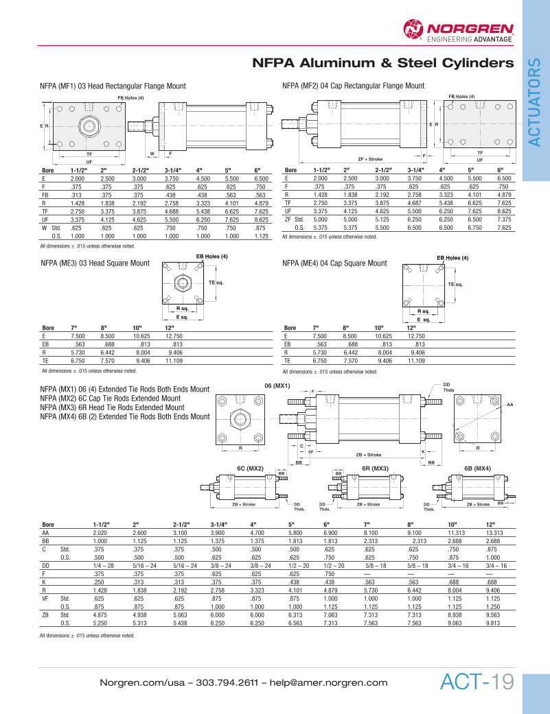
Bore 1-1/2" 2" 2-1/2" 3-1/4" 4" 5" 6"E 2.000 2.500 3.000 3.750 4.500 5.500 6.500F .375 .375 .375 .625 .625 .625 .750FB .313 .375 .375 .438 .438 .563 .563R 1.428 1.838 2.192 2.758 3.323 4.101 4.879TF 2.750 3.375 3.875 4.688 5.438 6.625 7.625UF 3.375 4.125 4.625 5.500 6.250 7.625 8.625W Std. .625 .625 .625 .750 .750 .750 .875
O.S. 1.000 1.000 1.000 1.000 1.000 1.000 1.125
RE
TF
UF
FW
FB Holes (4)
Bore 7" 8" 10" 12"E 7.500 8.500 10.625 12.750EB .563 .688 .813 .813R 5.730 6.442 8.004 9.406TE 6.750 7.570 9.406 11.109
Bore 7" 8" 10" 12"E 7.500 8.500 10.625 12.750EB .563 .688 .813 .813R 5.730 6.442 8.004 9.406TE 6.750 7.570 9.406 11.109
E sq.
R sq.
EB Holes (4)
TE sq.
E sq.
R sq.
EB Holes (4)
TE sq.
Bore 1-1/2" 2" 2-1/2" 3-1/4" 4" 5" 6" 7" 8" 10" 12"AA 2.020 2.600 3.100 3.900 4.700 5.800 6.900 8.100 9.100 11.313 13.313BB 1.000 1.125 1.125 1.375 1.375 1.813 1.813 2.313 2.313 2.688 2.688C Std. .375 .375 .375 .500 .500 .500 .625 .625 .625 .750 .875
O.S. .500 .500 .500 .625 .625 .625 .750 .625 .750 .875 1.000DD 1/4 – 28 5/16 – 24 5/16 – 24 3/8 – 24 3/8 – 24 1/2 – 20 1/2 – 20 5/8 – 18 5/8 – 18 3/4 – 16 3/4 – 16F .375 .375 .375 .625 .625 .625 .750 — — — —K .250 .313 .313 .375 .375 .438 .438 .563 .563 .688 .688R 1.428 1.838 2.192 2.758 3.323 4.101 4.879 5.730 6.442 8.004 9.406VF Std. .625 .625 .625 .875 .875 .875 1.000 1.000 1.000 1.125 1.125
O.S. .875 .875 .875 1.000 1.000 1.000 1.125 1.125 1.125 1.125 1.250ZB Std. 4.875 4.938 5.063 6.000 6.000 6.313 7.063 7.313 7.313 8.938 9.563
O.S. 5.250 5.313 5.438 6.250 6.250 6.563 7.313 7.563 7.563 9.063 9.813
NFPA (MF1) 03 Head Rectangular Flange Mount
Bore 1-1/2" 2" 2-1/2" 3-1/4" 4" 5" 6"E 2.000 2.500 3.000 3.750 4.500 5.500 6.500F .375 .375 .375 .625 .625 .625 .750R 1.428 1.838 2.192 2.758 3.323 4.101 4.879TF 2.750 3.375 3.875 4.687 5.438 6.625 7.625UF 3.375 4.125 4.625 5.500 6.250 7.625 8.625ZF Std. 5.000 5.000 5.125 6.250 6.250 6.500 7.375
O.S. 5.375 5.375 5.500 6.500 6.500 6.750 7.625
F
RE
TF
FB Holes (4)
ZF + Stroke UF
NFPA (MF2) 04 Cap Rectangular Flange Mount
NFPA (ME3) 03 Head Square Mount NFPA (ME4) 04 Cap Square Mount
R C
ZB + Stroke
F
R
DDThds
6C (MX2) 6B (MX4)
ZB + Stroke
BB
DDThds.
6R (MX3)
ZB + Stroke
BB
ZB + Stroke BB
VF K
AA
BB BB
DDThds.
DDThds.
06 (MX1)NFPA (MX1) 06 (4) Extended Tie Rods Both Ends MountNFPA (MX2) 6C Cap Tie Rods Extended MountNFPA (MX3) 6R Head Tie Rods Extended MountNFPA (MX4) 6B (2) Extended Tie Rods Both Ends Mount
All dimensions ± .015 unless otherwise noted.
All dimensions ± .015 unless otherwise noted.
All dimensions ± .015 unless otherwise noted. All dimensions ± .015 unless otherwise noted.
All dimensions ± .015 unless otherwise noted.
01 NFPA 4th_01NFPA 06 1/31/11 12:13 PM Page 19
ACT-20
NFPA Aluminum & Steel Cylinders
ACTUATORS
Norgren.com/usa – 303.794.2611 – [email protected]
UTXG
øTD
TL TL
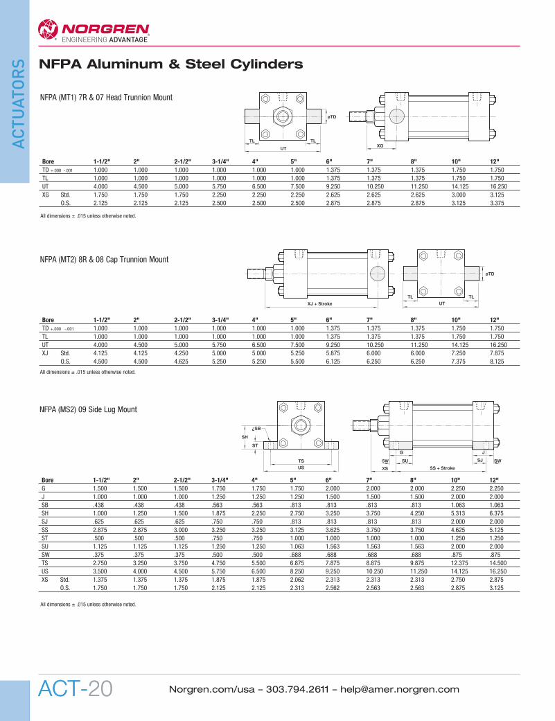
Bore 1-1/2" 2" 2-1/2" 3-1/4" 4" 5" 6" 7" 8" 10" 12"TD +.000 -.001 1.000 1.000 1.000 1.000 1.000 1.000 1.375 1.375 1.375 1.750 1.750TL 1.000 1.000 1.000 1.000 1.000 1.000 1.375 1.375 1.375 1.750 1.750UT 4.000 4.500 5.000 5.750 6.500 7.500 9.250 10.250 11.250 14.125 16.250XG Std. 1.750 1.750 1.750 2.250 2.250 2.250 2.625 2.625 2.625 3.000 3.125
O.S. 2.125 2.125 2.125 2.500 2.500 2.500 2.875 2.875 2.875 3.125 3.375
NFPA (MT1) 7R & 07 Head Trunnion Mount
øTD
UTTL
XJ + Stroke
A
TL
Bore 1-1/2" 2" 2-1/2" 3-1/4" 4" 5" 6" 7" 8" 10" 12"TD +.000 -.001 1.000 1.000 1.000 1.000 1.000 1.000 1.375 1.375 1.375 1.750 1.750TL 1.000 1.000 1.000 1.000 1.000 1.000 1.375 1.375 1.375 1.750 1.750UT 4.000 4.500 5.000 5.750 6.500 7.500 9.250 10.250 11.250 14.125 16.250XJ Std. 4.125 4.125 4.250 5.000 5.000 5.250 5.875 6.000 6.000 7.250 7.875
O.S. 4.500 4.500 4.625 5.250 5.250 5.500 6.125 6.250 6.250 7.375 8.125
NFPA (MT2) 8R & 08 Cap Trunnion Mount
XS
G J
TSUS SS + Stroke
SU SJ
ST
¿SB
SW
SH
SW
Bore 1-1/2" 2" 2-1/2" 3-1/4" 4" 5" 6" 7" 8" 10" 12"G 1.500 1.500 1.500 1.750 1.750 1.750 2.000 2.000 2.000 2.250 2.250J 1.000 1.000 1.000 1.250 1.250 1.250 1.500 1.500 1.500 2.000 2.000SB .438 .438 .438 .563 .563 .813 .813 .813 .813 1.063 1.063SH 1.000 1.250 1.500 1.875 2.250 2.750 3.250 3.750 4.250 5.313 6.375SJ .625 .625 .625 .750 .750 .813 .813 .813 .813 2.000 2.000SS 2.875 2.875 3.000 3.250 3.250 3.125 3.625 3.750 3.750 4.625 5.125ST .500 .500 .500 .750 .750 1.000 1.000 1.000 1.000 1.250 1.250SU 1.125 1.125 1.125 1.250 1.250 1.063 1.563 1.563 1.563 2.000 2.000SW .375 .375 .375 .500 .500 .688 .688 .688 .688 .875 .875TS 2.750 3.250 3.750 4.750 5.500 6.875 7.875 8.875 9.875 12.375 14.500US 3.500 4.000 4.500 5.750 6.500 8.250 9.250 10.250 11.250 14.125 16.250XS Std. 1.375 1.375 1.375 1.875 1.875 2.062 2.313 2.313 2.313 2.750 2.875
O.S. 1.750 1.750 1.750 2.125 2.125 2.313 2.562 2.563 2.563 2.875 3.125
NFPA (MS2) 09 Side Lug Mount
All dimensions ± .015 unless otherwise noted.
All dimensions ± .015 unless otherwise noted.
All dimensions ± .015 unless otherwise noted.
01 NFPA 4th_01NFPA 06 1/31/11 12:13 PM Page 20
ACT-21
NFPA Aluminum & Steel Cylinders
ACTUATORS
Norgren.com/usa – 303.794.2611 – [email protected] ACT-21
UM XI (Min.)
øTD
TL
UV
TM BDTLCustomer
Must SpecifyXI
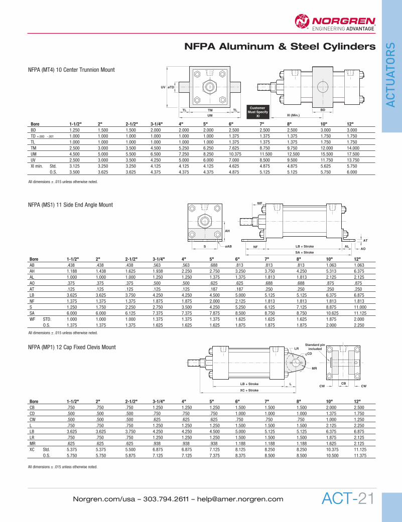
Bore 1-1/2" 2" 2-1/2" 3-1/4" 4" 5" 6" 7" 8" 10" 12"BD 1.250 1.500 1.500 2.000 2.000 2.000 2.500 2.500 2.500 3.000 3.000TD +.000 -.001 1.000 1.000 1.000 1.000 1.000 1.000 1.375 1.375 1.375 1.750 1.750TL 1.000 1.000 1.000 1.000 1.000 1.000 1.375 1.375 1.375 1.750 1.750TM 2.500 3.000 3.500 4.500 5.250 6.250 7.625 8.750 9.750 12.000 14.000UM 4.500 5.000 5.500 6.500 7.250 8.250 10.375 11.500 12.500 15.500 17.500UV 2.500 3.000 3.500 4.250 5.000 6.000 7.000 8.500 9.500 11.750 13.750XI min. Std. 3.125 3.250 3.250 4.125 4.125 4.125 4.625 4.875 4.875 5.625 5.750
O.S. 3.500 3.625 3.625 4.375 4.375 4.375 4.875 5.125 5.125 5.750 6.000
NFPA (MT4) 10 Center Trunnion Mount
SA + Stroke
A
LB + Stroke
AT
S øAB
AH
AOALNF
WF
Bore 1-1/2" 2" 2-1/2" 3-1/4" 4" 5" 6" 7" 8" 10" 12"AB .438 .438 .438 .563 .563 .688 .813 .813 .813 1.063 1.063AH 1.188 1.438 1.625 1.938 2.250 2.750 3.250 3.750 4.250 5.313 6.375AL 1.000 1.000 1.000 1.250 1.250 1.375 1.375 1.813 1.813 2.125 2.125AO .375 .375 .375 .500 .500 .625 .625 .688 .688 .875 .875AT .125 .125 .125 .125 .125 .187 .187 .250 .250 .250 .250LB 3.625 3.625 3.750 4.250 4.250 4.500 5.000 5.125 5.125 6.375 6.875NF 1.375 1.375 1.375 1.875 1.875 2.000 2.125 1.813 1.813 1.813 1.813S 1.250 1.750 2.250 2.750 3.500 4.250 5.250 6.125 7.125 8.875 11.000SA 6.000 6.000 6.125 7.375 7.375 7.875 8.500 8.750 8.750 10.625 11.125WF STD. 1.000 1.000 1.000 1.375 1.375 1.375 1.625 1.625 1.625 1.875 2.000
O.S. 1.375 1.375 1.375 1.625 1.625 1.625 1.875 1.875 1.875 2.000 2.250
NFPA (MS1) 11 Side End Angle Mount
XC + Stroke
LB + Stroke L
LR
¿CD
MR
CBCW
A
CW
Standard pinincluded
Bore 1-1/2" 2" 2-1/2" 3-1/4" 4" 5" 6" 7" 8" 10" 12"CB .750 .750 .750 1.250 1.250 1.250 1.500 1.500 1.500 2.000 2.500CD .500 .500 .500 .750 .750 .750 1.000 1.000 1.000 1.375 1.750CW .500 .500 .500 .625 .625 .625 .750 .750 .750 1.000 1.250L .750 .750 .750 1.250 1.250 1.250 1.500 1.500 1.500 2.125 2.250LB 3.625 3.625 3.750 4.250 4.250 4.500 5.000 5.125 5.125 6.375 6.875LR .750 .750 .750 1.250 1.250 1.250 1.500 1.500 1.500 1.875 2.125MR .625 .625 .625 .938 .938 .938 1.188 1.188 1.188 1.625 2.125XC Std. 5.375 5.375 5.500 6.875 6.875 7.125 8.125 8.250 8.250 10.375 11.125
O.S. 5.750 5.750 5.875 7.125 7.125 7.375 8.375 8.500 8.500 10.500 11.375
NFPA (MP1) 12 Cap Fixed Clevis Mount
All dimensions ± .015 unless otherwise noted.
All dimensions ± .015 unless otherwise noted.
All dimensions ± .015 unless otherwise noted.
01 NFPA 4th_01NFPA 06 1/31/11 12:13 PM Page 21

ACT-22
NFPA Aluminum & Steel Cylinders
ACTUATORS
Norgren.com/usa – 303.794.2611 – [email protected]
Bore 1-1/2" 2" 2-1/2" 3-1/4" 4" 5" 6" 7" 8"EB .313 .375 .375 .438 .438 .563 .563 .688 .688EF 1.125 1.313 1.438 1.500 1.625 1.688 1.750 1.750 1.750EL .750 .938 1.063 .875 1.000 1.063 1.000 1.125 1.125EO .250 .313 .313 .375 .375 .500 .500 .625 .625ET .500 .750 .750 1.000 1.250 1.500 1.500 1.750 2.063R 1.428 1.838 2.192 2.758 3.323 4.101 4.879 5.730 6.442SE 5.500 5.875 6.250 6.625 6.875 7.250 7.750 7.375 7.375ZE Std. 5.625 5.875 6.125 6.875 7.000 7.438 8.125 8.500 8.500
O.S. 6.000 6.250 6.500 7.125 7.250 7.688 8.375 8.750 8.750
EOZE + Stroke
¿EB Hole (4)
ET
EL
SE + Stroke
A
R EFEO
NFPA (MS7) 15 End Lug Mount
Bore 1-1/2" 2" 2-1/2" 3-1/4" 4" 5" 6"DD 1/4-28 5/16-24 5/16-24 3/8-24 3/8-24 1/2-20 1/2-20NT 1/4 – 20 5/16 – 18 3/8 – 16 1/2 – 13 1/2 – 13 5/8 – 11 3/4 – 10ND .375 .375 .500 .750 .750 .938 1.125R 1.428 1.838 2.192 2.758 3.323 4.101 4.879SN 2.250 2.250 2.375 2.625 2.625 2.875 3.125TN .625 .875 1.250 1.500 2.063 2.688 3.250XT Std. 1.938 1.938 1.938 2.438 2.438 2.438 2.813
O.S. 2.313 2.313 2.313 2.688 2.688 2.688 3.063
NT Tap ND Depth
XT SN + StrokeTN
R øDD 4 plcs (both ends)
16 Sleeve Nut Construction Side Tapped (Universal Mount)
Bore 1-1/2" 2" 2-1/2" 3-1/4" 4" 5" 6"F .375 .375 .375 .625 .625 .625 .750FB .313 .375 .375 .438 .438 .563 .563G 1.500 1.500 1.500 1.750 1.750 1.750 2.000R 1.428 1.838 2.192 2.758 3.323 4.101 4.879TF 2.750 3.375 3.875 4.688 5.438 6.625 7.625UF 3.375 4.125 4.625 5.500 6.250 7.625 8.625V Std. .250 .250 .250 .250 .250 .250 .250
O.S. .500 .500 .500 .375 .375 .375 .375W Std. .625 .625 .625 .750 .750 .750 .875
O.S. 1.000 1.000 1.000 1.000 1.000 1.000 1.125WF Std. 1.000 1.000 1.000 1.375 1.375 1.375 1.625
O.S. 1.375 1.375 1.375 1.625 1.625 1.625 1.875
VG
FW
WF
UFTF
RFB Holes (8)
NFPA (MF5) 20 Head Square Flange Mount
Bore 1-1/2" 2" 2-1/2" 3-1/4" 4" 5" 6"F .375 .375 .375 .625 .625 .625 .750FB .313 .375 .375 .438 .438 .563 .563J 1.000 1.000 1.000 1.250 1.250 1.250 1.500LB 3.625 3.625 3.750 4.250 4.250 4.500 5.000R 1.428 1.838 2.192 2.758 3.323 4.101 4.879TF 2.750 3.375 3.875 4.688 5.438 6.625 7.625UF 3.375 4.125 4.625 5.500 6.250 7.625 8.625XF Std. 4.625 4.625 4.750 5.625 5.625 5.875 6.625
O.S. 5.000 5.000 5.125 5.875 5.875 6.125 6.875ZF Std. 5.000 5.000 5.125 6.250 6.250 6.500 7.375
O.S. 5.375 5.375 5.500 6.500 6.500 6.750 7.625
UF TF
FB Holes (8)
A
ZF + Stroke
LB + StrokeJ
F
RXF + Stroke
NFPA (MF6) 21 Cap Square Flange Mount
Bore 1-1/2" 2" 2-1/2" 3-1/4" 4" 5" 6" 7" 8"CB .750 .750 .750 1.250 1.250 1.250 1.500 1.500 1.500CD .500 .500 .500 .750 .750 .750 1.000 1.000 1.000CW .500 .500 .500 .625 .625 .625 .750 .750 .750FL 1.125 1.125 1.125 1.875 1.875 1.875 2.250 2.250 2.250L .750 .750 .750 1.250 1.250 1.250 1.500 1.500 1.500LR .750 .750 .750 1.250 1.250 1.250 1.500 1.500 1.500M .500 .500 .500 .750 .750 .750 1.000 1.000 1.000MR .625 .625 .625 .938 .938 .938 1.188 1.188 1.188XD Std. 5.750 5.750 5.875 7.500 7.500 7.750 8.875 9.000 9.000
O.S. 6.125 6.125 6.250 7.750 7.750 8.000 9.125 9.250 9.250
XD + Stroke
L
MFL
øCD
MR
LR
CBCW CW
NFPA (MP2) 22 Detachable Cap Clevis Mount
Bore 1-1/2" 2" 2-1/2" 3-1/4" 4" 5" 6" 7" 8"CB .750 .750 .750 1.250 1.250 1.250 1.500 1.500 1.500CD .500 .500 .500 .750 .750 .750 1.000 1.000 1.000FL 1.125 1.125 1.125 1.875 1.875 1.875 2.250 2.250 2.250L .750 .750 .750 1.250 1.250 1.250 1.500 1.500 1.500LR .750 .750 .750 1.250 1.250 1.250 1.500 1.500 1.500M .500 .500 .500 .750 .750 .750 1.000 1.000 1.000MR .625 .625 .625 .938 .938 .938 1.188 1.188 1.188XD Std. 5.750 5.750 5.875 7.500 7.500 7.750 8.875 9.000 9.000
O.S. 6.125 6.125 6.250 7.750 7.750 8.000 9.125 9.250 9.250
FL CBXD + Stroke
L
M
øCD
MR
LR
NFPA (MP4) 42 Detachable Cap Eye Mount
All dimensions ± .015 unless otherwise noted.
01 NFPA 4th_01NFPA 06 1/31/11 12:14 PM Page 22

ACT-23
NFPA Aluminum & Steel Cylinders
ACTUATORS
Norgren.com/usa – 303.794.2611 – [email protected]
Bore 1-1/2" 2" 2-1/2" 3-1/4" 4" 5" 6" 7" 8"AM .750 .750 .750 1.000 1.000 1.000 1.250 1.250 1.250BI .438 .438 .438 .656 .656 .656 .875 .875 .875CB .375 .375 .375 .562 .562 .562 .75 .75 .75DC .500 .500 .500 .750 .750 .750 1.000 1.000 1.000FT .625 .625 .625 1.000 1.000 1.000 1.250 1.250 1.250KL .969 .969 .969 1.406 1.406 1.406 1.719 1.719 1.719XC Std. 5.375 5.375 5.500 6.875 6.875 7.125 8.125 8.250 8.250
O.S. 5.750 5.750 5.875 7.125 7.125 7.375 8.375 8.500 8.500
AM
øDC
XC + Stroke
FT
KL
CB
BI
52 (Not NFPA) Spherical Bearing Mount
Bore 1-1/2" 2" 2-1/2" 3-1/4" 4" 5" 6"G 1.500 1.500 1.500 1.750 1.750 1.750 2.000SH 1.250 1.500 1.875 2.375 2.750 3.500 4.000 SS 2.875 2.875 3.000 3.250 3.250 3.125 3.625ST .250 .250 .375 .500 .500 .750 .750SU 1.125 1.125 1.125 1.250 1.250 1.063 1.313SW .375 .375 .375 .500 .500 .688 .688TS 2.750 3.250 3.750 4.750 5.500 6.875 7.875US 3.500 4.000 4.500 5.750 6.500 8.250 9.250XS Std. 1.375 1.375 1.375 1.875 1.875 2.063 2.313
O.S. 1.750 1.750 1.750 2.125 2.125 2.313 2.563
XS
GTSUS SS + Stroke
SU
ST
SW
SH
60 Base (Not NFPA) Bar Mount
XC + StrokeL M
CB
øCD
MR
LR
Bore 1-1/2" 2" 2-1/2" 3-1/4" 4" 5" 6" 7" 8" 10" 12"CB .750 .750 .750 1.250 1.250 1.250 1.500 1.500 1.500 2.000 2.500CD .500 .500 .500 .750 .750 .750 1.000 1.000 1.000 1.375 1.750L .750 .750 .750 1.250 1.250 1.250 1.500 1.500 1.500 2.125 2.250LR .750 .750 .750 1.250 1.250 1.250 1.500 1.500 1.500 1.875 2.125M .500 .500 .500 .750 .750 .750 1.000 1.000 1.000 1.375 1.750MR .625 .625 .625 .938 .938 .938 1.188 1.188 1.188 1.625 2.125XC Std. 5.375 5.375 5.500 6.875 6.875 7.125 8.125 8.250 8.250 10.375 11.125
O.S. 5.750 5.750 5.875 7.125 7.125 7.375 8.375 8.500 8.500 10.500 11.375
NFPA (MP3) 32 Cap Fixed Eye
ZL + Stroke
WF
ZM + 2x Stroke
D
LD + Stroke
Bore 1-1/2" 2" 2-1/2" 3-1/4" 4" 5" 6" 7" 8" 10" 12"LD 4.125 4.125 4.250 4.750 4.750 5.000 5.500 5.625 5.625 6.625 7.125WF Std. 1.000 1.000 1.000 1.375 1.375 1.375 1.625 1.625 1.625 1.875 2.000
O.S. 1.375 1.375 1.375 1.625 1.625 1.625 1.875 1.875 1.875 2.000 2.250ZL Std. 5.375 5.438 5.563 6.500 6.500 6.813 7.563 7.813 7.813 10.375 11.125
O.S. 5.750 5.813 5.938 6.750 6.750 7.063 7.813 8.125 8.125 10.625 11.625ZM Std. 6.125 6.125 6.250 7.500 7.500 7.750 8.750 8.875 8.875 9.250 9.675
O.S. 6.875 6.875 7.000 8.000 8.000 8.250 9.250 9.375 9.375 9.375 10.375
NFPA (MX0) 05 Basic with Double Rod End Cylinder
All dimensions ± .015 unless otherwise noted.
All dimensions ± .015 unless otherwise noted.
All dimensions ± .015 unless otherwise noted.
All dimensions ± .015 unless otherwise noted.
01 NFPA 4th_01NFPA 06 1/31/11 12:14 PM Page 23
ACT-24
NFPA Aluminum & Steel Cylinders
ACTUATORS
Norgren.com/usa – 303.794.2611 – [email protected]
ER Radius
LCE
KK Thds. CH Across Hex Flats
CBCW CW
øCD
A
ER RadiusCD
KK Thds.
øCD
CBCD
CD
CE
A
WøD
K
H
ZerkFitting
øB
C
KK Thds. J
˚ a Clevis Mounted
N
L
CE
KK Thds.
CW CW
øCD
CB
CH
AFH
KK Thds.
52025 52026 52027 52010 52029 52030 52085KK 7/16 – 20 1/2 – 20 5/8 – 18 3/4 – 16 7/8 – 14 1 – 14 1-1/4 – 12AF .688 .750 .938 1.125 1.313 1.500 1.875H .250 .313 .375 .422 .484 .547 .719
52092 52068 52082 52070 52093 52083 52075KK 1-3/8 – 12 1-1/2 – 12 1-3/4 – 12 1-7/8 – 12 2 – 12 2-1/4 – 12 2-1/2 – 12AF 2.063 2.250 2.625 2.938 3.125 3.500 3.875H .781 .844 .969 1.031 1.094 1.203 1.453
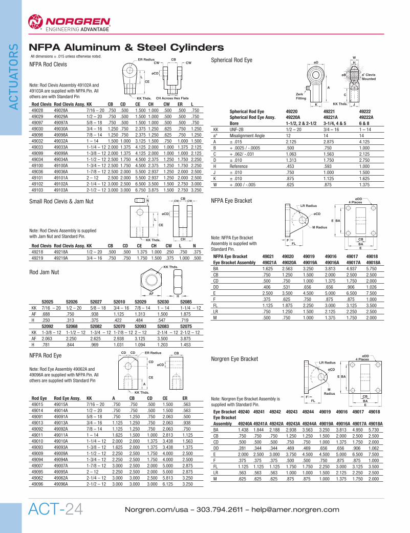
Spherical Rod Eye 49220 49221 49222Spherical Rod Eye Assy. 49220A 49221A 49222ABore 1-1/2, 2 & 2-1/2 3-1/4, 4 & 5 6 & 8
KK UNF-2B 1/2 – 20 3/4 – 16 1 – 14a° Misalignment Angle 12 14 14A ± .015 2.125 2.875 4.125B + .0025 / -.0005 .500 .750 1.000C + .062/ -.031 1.063 1.563 2.125D ± .010 1.313 1.750 2.750H Reference .453 .593 1.000J ± .010 .750 1.000 1.500K ± .010 .875 1.125 1.625W + .000 / -.005 .625 .875 1.375
NFPA Rod Clevis
NFPA Rod Eye
Spherical Rod Eye
Small Rod Clevis & Jam Nut
Rod Jam Nut
Rod Clevis Rod Clevis Assy. KK CB CD CE CH CW L N49218 49218A 1/2 – 20 .500 .500 1.375 1.000 .250 .750 .37549219 49219A 3/4 – 16 .750 .750 1.750 1.500 .375 1.000 .500
Note: Rod Clevis Assembly is suppliedwith Jam Nut and Standard Pin.
Note: Rod Eye Assembly 49062A and49096A are supplied with NFPA Pin. Allothers are supplied with Standard Pin
Note: Rod Clevis Assembly 49102A and49103A are supplied with NFPA Pin. Allothers are with Standard Pin
Rod Eye Rod Eye Assy. KK A CB CD CE ER49015 49015A 7/16 – 20 .750 .750 .500 1.500 .56349014 49014A 1/2 – 20 .750 .750 .500 1.500 .56349091 49091A 5/8 – 18 .750 1.250 .750 2.063 .50049013 49013A 3/4 – 16 1.125 1.250 .750 2.063 .93849092 49092A 7/8 – 14 1.125 1.250 .750 2.063 .75049011 49011A 1 – 14 1.625 1.500 1.000 2.813 1.12549010 49010A 1-1/4 – 12 2.000 2.000 1.375 3.438 1.56349093 49093A 1-3/8 – 12 1.625 2.000 1.375 3.438 1.37549009 49009A 1-1/2 – 12 2.250 2.500 1.750 4.000 2.50049094 49094A 1-3/4 – 12 2.250 2.500 1.750 4.000 2.50049007 49007A 1-7/8 – 12 3.000 2.500 2.000 5.000 2.87549095 49095A 2 – 12 2.250 2.500 2.000 5.000 2.87549062 49062A 2-1/4 – 12 3.000 3.000 2.500 5.813 3.25049096 49096A 2-1/2 – 12 3.000 3.000 3.000 6.125 3.250
Rod Clevis Rod Clevis Assy. KK CB CD CE CH CW ER L49028 49028A 7/16 – 20 .750 .500 1.500 1.000 .500 .500 .75049029 49029A 1/2 – 20 .750 .500 1.500 1.000 .500 .500 .75049097 49097A 5/8 – 18 .750 .500 1.500 1.000 .500 .500 .75049030 49030A 3/4 – 16 1.250 .750 2.375 1.250 .625 .750 1.25049098 49098A 7/8 – 14 1.250 .750 2.375 1.250 .625 .750 1.25049032 49032A 1 – 14 1.500 1.000 3.125 1.500 .750 1.000 1.50049033 49033A 1-1/4 – 12 2.000 1.375 4.125 2.000 1.000 1.375 2.12549099 49099A 1-3/8 – 12 2.000 1.375 4.125 2.000 1.000 1.000 2.12549034 49034A 1-1/2 – 12 2.500 1.750 4.500 2.375 1.250 1.750 2.25049100 49100A 1-3/4 – 12 2.500 1.750 4.500 2.375 1.250 1.750 2.25049036 49036A 1-7/8 – 12 2.500 2.000 5.500 2.937 1.250 2.000 2.50049101 49101A 2 – 12 2.500 2.000 5.500 2.937 1.250 2.000 2.50049102 49102A 2-1/4 – 12 3.000 2.500 6.500 3.500 1.500 2.750 3.00049103 49103A 2-1/2 – 12 3.000 3.000 6.750 3.875 1.500 2.750 3.250
FFL
E
CB
øDD4 Places
BA
BAE
LR Radius
øCD
M Radius
FFL
E
CB
øDD4 Places
BA
BA
E
LR Radius
øCD
M Radius
NFPA Eye Bracket
NFPA Eye Bracket 49021 49020 49019 49016 49017 49018Eye Bracket Assembly 49021A 49020A 49019A 49016A 49017A 49018ABA 1.625 2.563 3.250 3.813 4.937 5.750CB .750 1.250 1.500 2.000 2.500 2.500CD .500 .750 1.000 1.375 1.750 2.000DD .406 .531 .656 .656 .906 1.026E 2.500 3.500 4.500 5.000 6.500 7.500F .375 .625 .750 .875 .875 1.000FL 1.125 1.875 2.250 3.000 3.125 3.500LR .750 1.250 1.500 2.125 2.250 2.500M .500 .750 1.000 1.375 1.750 2.000
Norgren Eye Bracket
Eye Bracket 49240 49241 49242 49243 49244 49019 49016 49017 49018Eye BracketAssembly 49240A 49241A 49242A 49243A 49244A 49019A 49016A 49017A 49018ABA 1.438 1.844 2.188 2.938 3.563 3.250 3.813 4.950 5.730CB .750 .750 .750 1.250 1.250 1.500 2.000 2.500 2.500CD .500 .500 .500 .750 .750 1.000 1.375 1.750 2.000DD .281 .344 .344 .469 .469 .656 .656 .906 1.062E 2.000 2.500 3.000 3.750 4.500 4.500 5.000 6.500 7.500F .375 .375 .375 .500 .500 .750 .875 .875 1.000FL 1.125 1.125 1.125 1.750 1.750 2.250 3.000 3.125 3.500LR .563 .563 .563 1.000 1.000 1.500 2.125 2.250 2.500M .625 .625 .625 .875 .875 1.000 1.375 1.750 2.000
Note: NFPA Eye BracketAssembly is supplied withStandard Pin.
Note: Norgren Eye Bracket Assembly issupplied with Standard Pin.
All dimensions ± .015 unless otherwise noted.
01 NFPA 4th_01NFPA 06 1/31/11 12:14 PM Page 24

ACT-25
NFPA Aluminum & Steel Cylinders
ACTUATORS
Norgren.com/usa – 303.794.2611 – [email protected]
NFPA Pin 49006-R 49005-R 49004-R 49003 49002 49001 49000 49126 49127CD. 500 .750 1.000 1.375 1.750 2.000 2.000 2.500 3.000LH 2.219 3.125 3.750 4.750 5.812 5.812 6.312 6.875 6.875LP 1.875 2.750 3.250 4.250 5.250 5.281 5.770 6.312 6.344D – – – .173 .173 .204 .204 .219 .250
øCD
LPLH
øDNFPA Pin
F
E
CB
øDD4 Places
FL
BA
BA
E
CW CW
LR Radius
øCD
M Radius
NFPA Clevis Bracket
øCD
HP
LPLH
Standard Pin
Norgren Clevis Bracket
Norgren Clevis Bracket 49022 49023 49024 49027 49025 49026Clevis Bracket Assembly 49022A 49023A 49024A 49027A 49025A 49026ACB .750 1.250 1.500 2.000 2.500 2.500CD .500 .750 1.000 1.375 1.750 2.000CW .500 .625 .750 1.000 1.250 1.500DD .406 .531 .656 .656 .906 1.026E 3.500 5.000 6.500 8.000 10.000 12.000F .500 .625 .750 .875 .875 1.000FL 1.500 1.875 2.250 3.000 3.625 4.520LR .750 1.188 1.500 2.000 2.750 3.188M .500 .750 1.000 1.375 1.750 2.250MR .625 .906 1.250 1.656 2.219 2.781R 2.547 3.828 4.953 5.734 7.500 9.938
MR Radius
FL
øDD4 Places
LRRadius
ER
M
F
CW CWCB
CD .001 Pin Dia. +
NFPA Clevis Bracket 49250 49251 49252Clevis Bracket Assembly 49250A 49251A 49252ABA 1.625 2.563 3.250CB .750 1.250 1.500CD .500 .750 1.000CW .500 .625 .750DD 3/8 – 24 1/2 – 20 5/8 – 18E 2.500 3.500 4.500F .375 .625 .750FL 1.125 1.875 2.250LR .750 1.250 1.500M .500 .813 1.000
Note: NFPA Clevis Bracket Assemblyis supplied with Standard Pin.
Note: Norgren Clevis Bracket Assemblyis supplied with Standard Pin.
Note: ø.500, .750, 1.000 are Retainer typedesign ø1.375 and larger are Cotter Pin design.
Std. Pin 49207* 49208* 49206 49205 49204 49203 49202 49201CD .500 .750 .500 .750 1.000 1.375 1.750 2.000HP .156 .156 .156 .156 .203 .250 .250 .250LH 1.421 2.000 2.250 3.000 3.500 5.000 6.000 6.000LP 1.266 1.843 2.093 2.843 3.297 4.500 5.500 5.500
All dimensions ± .015 unless otherwise noted.
All dimensions ± .015 unless otherwise noted.
All dimensions ± .015 unless otherwise noted. All dimensions ± .015 unless otherwise noted.
G Across Flats
øF Shank
.062Radial Float2˚ Spherical
Motion
øB
A Thds.
A Thds.
E E
DC
H AcrossFlats
Rod Alignment CouplerThe Rod Alignment Coupler allows 1/16" of radial float and2° of spherical movement. This prevents cylinder bindingdue to misalignment thus extending bearing and seal life,and permits greater tolerance between the centerline of thecylinder and mating part for simplified installation.
B 1.250 1.250 1.250 1.750 1.750 2.500 2.500 3.250 3.250C 2.000 2.000 2.000 2.312 2.312 2.937 2.937 4.375 4.375D .500 .500 .500 .500 .500 .500 .500 .812 .812E .750 .750 .750 1.125 1.125 1.625 1.625 2.250 2.250F .625 .625 .625 .969 .969 1.375 1.375 1.750 1.750G .500 .500 .500 .812 .812 1.156 1.156 1.500 1.500H 1.125 1.125 1.125 1.500 1.500 2.250 2.250 3.000 3.000Max Pull (lbs.) 10,000 14,000 19,000 34,000 39,000 64,000 78,000 134,000 134,000
Rod Alignment Coupler Dimensions
CC-1-07 CC-1-08 CC-1-10 CC-1-12 CC-1-14 CC-1-16 CC-1-20 CC-1-24 CC-1-28A 7/16 – 20 1/2 – 20 5/8 – 18 3/4 – 16 7/8 – 14 1 – 14 1-1/4 – 12 1- 1/2 – 12 1-3/4 – 12
(31.75) (31.75) (31.75) (44.45) (44.45) (63.50) (63.50) (82.50) (82.50)(50.80) (50.80) (50.80) (58.72) (58.72) (74.60) (74.60) (111.13) (111.13)(12.70) (12.70) (12.70) (12.70) (12.70) (12.70) (12.70) (20.62) (20.62)(19.05) (19.05) (19.05) (28.58) (28.58) (41.28) (41.28) (57.15) (57.15)(28.58) (28.58) (28.58) (24.61) (24.61) (34.93) (34.93) (44.45) (44.45)(12.70) (12.70) (12.70) (20.62) (20.62) (29.36) (29.36) (38.10) (38.10)(28.58) (28.58) (28.58) (38.10) (38.10) (57.15) (57.15) (76.20) (76.20)
01 NFPA 4th_01NFPA 06 1/31/11 12:14 PM Page 25
ACT-26
NFPA Aluminum & Steel Cylinders
ACTUATORS
Norgren.com/usa – 303.794.2611 – [email protected]
Air-Oil Tank Volumes (cubic inches)
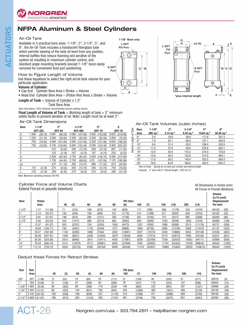
Air-Oil TankAvailable in 5 practical bore sizes: 1-1/8", 2", 3-1/4", 5", and8", the Air-Oil Tank includes a translucent fiberglass tubewhich permits viewing of the tank oil level from any position,internal baffles that reduce foaming and aeration of thesystem oil resulting in maximum cylinder control, andstandard angle mounting brackets (except 1-1/8" bore) easilyremoved for convenient fluid port positioning.
øJ (4)L NPTFill Port
K NPT Port
*C *B
D
A
K NPTPort
GH
L NPTFill
Port
F E
*D*C*B
EA
1-1/8" Bore only
*plus internal length
Bore 1-1/8" 2" 3-1/4" 5" 8"Area .995 sq." 3.14 sq." 8.30 sq." 19.64 sq." 50.26 sq."6" 5.9 18.6 49.8 117.8 301.58" 7.9 25.1 66.4 157.1 402.010" 9.9 31.4 83.0 196.4 502.612" 11.9 37.6 99.6 235.6 603.114" 13.9 43.9 116.2 274.9 703.616" 15.9 50.2 132.8 314.2 804.118" 17.9 56.5 149.4 353.5 904.520" 19.9 62.8 166.0 392.8 1005.2
Internal Length of Tank
Air-Oil Tank Dimensions
How to Order: Specify air-oil tank part number and internal length.Example: 2" bore with 6" internal length = AOT-04 x 6
Note: Maximum operating pressure 250 PSI.
1.500 2.687 4.000 5.625 8.6251.250 2.000 2.500 2.500 3.000.750 4.000 5.000 5.250 6.625.750 4.750 6.000 6.500 8.000
.375 .500 .500 .687
.125 .187 .187 .2502.500 3.750 5.500 8.5001.750 2.750 4.25 7.125.437 .562 .690 .812
.125 .375 .500 .500 .750
.125 .250 .375 .375 .500
Bore 1-1/8" 2" 3-1/4" 5" 8AOT-225 AOT-04 AOT-065 AOT-10 AOT-16
A (38.10) (68.25) (101.60) (142.88) (219.08)B (31.75) (50.80) (63.50) (63.50) (76.20)C (19.05) (101.60) (127.00) (127.00) (168.28)D (19.05) (120.65) (152.40) (152.40) (203.20)E (9.53) (12.70) (12.70) (17.45)F (3.18) (4.75) (4.75) (6.35)G (63.50) (95.25) (139.70) (215.90)H (44.45) (69.85) (107.95) (180.98)øJ (11.10) (14.27) (17.53) (20.62)K (3.18) (9.53) (12.70) (12.70) (19.05)L (3.18) (6.35) (9.53) (9.53) (12.70)
Volume of Cylinder:• Cap End Cylinder Bore Area x Stroke = Volume• Head End Cylinder Bore Area – (Piston Rod Area) x Stroke = VolumeLength of Tank = Volume of Cylinder x 1.3*
Tank Bore Area(See chart below.) *30% minimum recommended reserve working volume.
Final Length of Volume of Tank = Working length of tank + 2" minimumsafety factor to prevent aeration of oil. Note: Length must be at least 3".
How to Figure Length of VolumeUse these equations to select the right air/oil tank volume for yourparticular application.
All Dimensions in Inches (mm)All Forces in Pounds (Newtons)
VolumeCu Ft (cm3)
Rod Rod PSI (bar) Displacement Area 40 (3) 60 (4) 80 (6) 100 (7) 150 (10) 200 (14) Per Inch
.307 12 18 25 31 46 61 .00018
.785 31 47 63 78 118 157 .000451.485 59 89 119 149 222 297 .000862.404 96 144 192 240 360 480 .001393.142 126 189 251 314 471 628 .001824.909 196 295 393 491 736 981 .00284
5/8" (1.98) (53) (80) (111) (138) (205) (271) (5)1" (5.06) (138) (209) (280) (351) (525) (698) (13)1-3/8" (9.58) (262) (396) (529) (663) (997) (1321) (24)1-3/4" (15.51) (423) (641) (854) (1068) (1601) (2135) (39)2" (20.16) (559) (839) (1118) (1398) (2096) (2795) (52)2-1/2" (31.67) (873) (1310) (1747) (2184) (3275) (4367) (80)
Deduct these Forces for Retract Strokes
Cylinder Force and Volume ChartsExtend Forces in pounds (newtons)
1-1/2" 1.77 71 106 142 177 266 353 .001022" 3.14 126 189 251 314 471 628 .001822-1/2" 4.91 196 295 393 491 737 982 .002843-1/4" 8.30 332 498 664 830 1245 1659 .004804" 12.57 503 754 1005 1257 1886 2513 .007275" 19.64 785 1178 1571 1964 2946 3928 .011376" 28.27 1130 1696 2262 2827 4240 5654 .016367" 38.49 1540 2309 3079 3849 5774 7698 .022278" 50.26 2010 3015 4020 5026 7539 10052 .0290910" 78.54 3141 4712 6283 7854 11781 15700 .0454512" 113.10 4524 6786 9048 11310 16965 22620 .06545
(11.40) (315) (472) (629) (786) (1179) (1570) (29)(20.27) (559) (839) (1119) (1398) (2097) (2793) (52)(31.67) (874) (1311) (1748) (2185) (3277) (4368) (80)(53.32) (1477) (2215) (2953) (3692) (5538) (7379) (136)(81.07) (2237) (3355) (4473) (5592) (8388) (11178) (206)
(126.71) (3491) (5240) (6988) (8736) (13104) (17472) (322)(182.39) (5026) (7544) (10061) (12574) (18860) (25149) (463)(247.91) (6831) (10242) (13658) (17074) (25613) (34148) (631)(324.26) (8940) (13411) (17881) (22356) (33533) (44711) (829)(506.74) (13974) (20961) (27948) (34935) (52402) (69834) (1282)(729.72) (20123) (30184) (40246) (50307) (75460) (100614) (1852)
VolumeCu Ft (cm3)
Bore Piston PSI (bar) Displacement Area 40 (3) 60 (4) 80 (6) 100 (7) 150 (10) 200 (14) Per Inch
01 NFPA 4th_01NFPA 06 1/31/11 12:14 PM Page 26