Newgy Robo Pong 1050 2050 Manual
50
IMPORTANT NOTICE Addendum To Newgy Table Tennis Robot Owner’s Manual For Robo-Pong 2050/1050 (Manufactured after October, 2012) As of October, 2012, Newgy made a change to Robo-Pong 2050 & 1050. These models now use a Detent Pin instead of a separate Steel Ball and Steel Ball Spring. These parts are/ were responsible for “clicking” the head into position when rotating it to select a type of spin. Previously, the combination of the Steel Ball and Steel Ball Spring held the rotational position of the head as the head was spun to select the spin type. A result of using two separate parts was that during assembly the spring needed to be kept under tension, making assembly slightly more difficult. And during disassembly, because the spring was under tension, if the user wasn’t careful, the spring could release its tension and throw out the Steel Ball, potentially losing it. Combining these parts into a detent pin resolves these problems during assembly and disassembly. A detent pin encloses these two parts in a brass tube and the brass tube is crimped shut so the spring and ball cannot come apart. This simplifies assembly and disassembly. Making this change also necessitated enlarging the hole into which the Steel Ball and Spring were inserted. This change was made to the Left Head Housing. It is important to always match these parts properly for proper functioning. A Detent Pin should always be used with the 2050-173 Left Head Housing. It will not fit into the hole of the 2050- 172 Left Head Housing, which was used for the Steel Ball and Steel Ball Spring. You also should never use a Steel Ball and Spring with a 2050-173 housing as the hole will be too large to hold these two parts in their proper positions. 2050- 173 and 2050-172 are identical except for the size of the hole into which the Detent Pin or Steel Ball and Spring are in- serted. Because of this change to a Detent Pin, parts of the Own- er’s Manual are now incorrect. On page 44, Figure D chang- es to show the new Detent Pin instead of the Steel Ball and Spring (shown below). And on page 47, the PARTS LIST FOR ROBOT BODY ASSEMBLY AND BALL BUCKET changes in a similar way (on reverse side of this sheet). Page 1 of 2 ROBOT HEAD ASSEMBLY 1. When disassembling the robot head, do not let the Detent Pin (67) fall out of the Left Housing (65) since it's small and easy to lose! Work atop a towel to prevent loss of parts. 2. A small amount of Superglue ® (cyanoacry- late) holds the Ball Discharge Spring (58) onto the Discharge Tube (56). Scrape off old glue before replacing the spring. 3. Keep Friction Block (79) and Discharge Wheel (78, Figure C) clean for correct ball speeds. See page 37 for cleaning procedure. FIGURE D Red Wire Attaches To Terminal With Polarity Marker 58 See Note #2 71 77 71 56 66 80 65 79 See Note #3 See Note #1 67
-
Upload
oprea-vasile -
Category
Documents
-
view
570 -
download
35
description
Table tenis robot
Transcript of Newgy Robo Pong 1050 2050 Manual

IMPORTANT NOTICEAddendum To
Newgy Table Tennis Robot Owner’s ManualFor Robo-Pong 2050/1050 (Manufactured after October, 2012)
As of October, 2012, Newgy made a change to Robo-Pong 2050 & 1050. These models now use a Detent Pin instead of a separate Steel Ball and Steel Ball Spring. These parts are/were responsible for “clicking” the head into position when rotating it to select a type of spin.
Previously, the combination of the Steel Ball and Steel Ball Spring held the rotational position of the head as the head was spun to select the spin type. A result of using two separate parts was that during assembly the spring needed to be kept under tension, making assembly slightly more difficult. And during disassembly, because the spring was under tension, if the user wasn’t careful, the spring could release its tension and throw out the Steel Ball, potentially losing it.
Combining these parts into a detent pin resolves these problems during assembly and disassembly. A detent pin encloses these two parts in a brass tube and the brass tube is crimped shut so the spring and ball cannot come apart. This simplifies assembly and disassembly.
Making this change also necessitated enlarging the hole into which the Steel Ball and Spring were inserted. This change was made to the Left Head Housing. It is important to always match these parts properly for proper functioning.
A Detent Pin should always be used with the 2050-173 Left Head Housing. It will not fit into the hole of the 2050-172 Left Head Housing, which was used for the Steel Ball and Steel Ball Spring. You also should never use a Steel Ball and Spring with a 2050-173 housing as the hole will be too large to hold these two parts in their proper positions. 2050-173 and 2050-172 are identical except for the size of the hole into which the Detent Pin or Steel Ball and Spring are in-serted.
Because of this change to a Detent Pin, parts of the Own-er’s Manual are now incorrect. On page 44, Figure D chang-es to show the new Detent Pin instead of the Steel Ball and Spring (shown below). And on page 47, the Parts List For robot body assembLy and baLL bucket changes in a similar way (on reverse side of this sheet).
Page 1 of 2
RObOT HEAd AssEMbly
1. When disassembling the robot head, do not let the Detent Pin (67) fall out of the Left Housing (65) since it's small and easy to lose! Work atop a towel to prevent loss of parts.2. A small amount of Superglue® (cyano acrylate) holds the Ball Discharge Spring (58) onto the Discharge Tube (56). Scrape off old glue before replacing the spring.3. Keep Friction Block (79) and Discharge Wheel (78, Figure C) clean for correct ball speeds. See page 37 for cleaning procedure.
FIGURE dRed Wire Attaches To Terminal With Polarity Marker
58See Note #2
71
777156
6680
65
79See
Note #3
SeeNote #1
67
Page 2 of 2
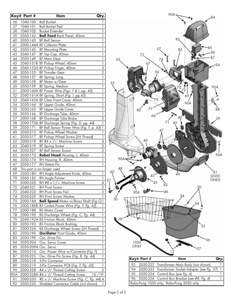
Key# Part # Item Qty. 36 1040100 Ball Bucket1 1 37 1040101 Ball Bucket Pad1 1 38 1040105 Bucket Extender1 1 39 2050142 ball Feed Back Panel, 40mm 1 40 2050143 BF Ball Sensor 1 41 2000144A BF Collector Plate2 1 42 2050145 BF Mounting Plate 1 43 2040147 BF Top Cap, 40mm 1 44 2050149 BF Main Gear 1 45 2040151B BF Pickup Wheel, 40mm 1 46 2040153A BF Pickup Finger, 40mm 3 47 2050155 BF Transfer Gear 2 48 2050157 BF Spring, Long 1 49 2050158 BF Motor w/Gear 1 50 2050159 BF Spring, Medium 1 51 2000160A BF Power Wire (Figs. F & I, pg. 45) 1 52 2040161A BF Spring, Short (Fig. I, pg 45) 1 53 2040162A BF Clear Front Cover, 40mm 1 54 2050164 BF Upper Guide, 40mm 1 55 2050165 BF Upper Guide Cover 1 56 2050166 BF Discharge Tube, 40mm 1 57 2000168 BF Discharge Tube Brake 2 58 2000170A BF Discharge Spring (Fig. D, pg. 44) 1 59 2050171 BF Ball Sensor Power Wire (Fig. F, p. 45) 1 60 2050313 BF Pickup Wheel Washer 1 61 2050317 BF Pickup Wheel Screw (LH Thread) 1 62 2000318 BF #4 x 5/16″ Machine Screw 4 63 2040319 BF Spring Screw 3 64 2050327 BF Ball Sensor Screw 2 65 2050173 Robot Head Housing, L, 40mm 1 66 2050174 RH Housing, R, 40mm 1 67 2050177 RH Detent Pin 1 68 This part is no longer used 69 2050180 RH Angle Adjustment Knob, 40mm 1 70 2050182 RH Angle Pointer 1 71 2000320 RH #8 x 13/16″ Machine Screw 4 72 2040321 RH Pivot Screw 2 73 2040323 RH Pivot Screw Nut 3 74 2050329 RH Pivot Screw Washer 1 75 2000184 ball speed Motor w/Brass Shaft (Fig C) 1 76 2000186B BS Coiled Power Wire (Fig. F, Pg. 45) 1 77 2000188 BS Motor Cover 1 78 2000190 BS Discharge Wheel (Fig. C, Pg. 44) 1 79 2040192A BS Friction Block, 40mm 1 80 2050193 BS Friction Block Bushing 1 81 2000324 BS Discharge Wheel Screw (LH Thread) 1 82 2050196 Oscillator Pivot Guide, 40mm 1 83 2050199 Osc. Drive Pin 1 84 2050204 Osc. Servo Cover 1 85 2050209A Osc. Servo 1 86 2050210 Osc. Power Wire w/Connector (Fig. F) 1 87 2050325 Osc. Drive Pin Screw (Fig. B, Pg. 44) 1 88 2050218 5Pin Connector 1 89 2050219 5Pin Connector PCB (Fig. F, Pg. 45) 1 90 2000328 #4 x 3/8″ Thread Cutting Screw 3 90A 2000328A #4 x 3/8″ Thread Cutting Screw 161/192
91 2000330 #2 x 1/4″ Machine Screw (Fig. C, Pg. 44) 4 92 2050220 Shielded Connector Cable (not shown) 1
Key# Part # Item Qty.
93 2050222 Transformer Main Body (not shown) 1 94 2050223 Transformer Socket Adapter (see Pg. 37) 1 95 2050224 Control Box (see Pg. 6) 1 96 2050226 Control Box Bracket (see #8, Pg. 4) 11RoboPong 1050 only; 2RoboPong 2050 only
41(2050ONLY)
90A
90A
71
56
66
6567
57
90A
90A
39
88
82
7269
79
80
7274
70
84
9087
85
54
83
53
38
48
49
90A
34
34
12
4042
45
50
62
43
361050 ONLY
6044
61
37
32
47
46
77
90A30

•Quick Set-up, 1050 ..3
•Quick Set-up, 2050 ..5
•OperatiOn ................6
•rObOt pOSitiOnS ......18
•MiSc. adjuStMentS ...19
•drill diagraMS ........21
•Speed calib. target ..27
•rObO-SOft ..............28
•iMpOrtant nOticeS ...34
•take-dOwn, 2050 ...35
•Maintenance ...........37
•acceSSOrieS .............38
•chip replaceMent .....40
•trOubleShOOting .....41
•explOded ViewS .......44
•partS liSt ...............46
•warranty & repair .48
Newgy INdustrIes, INc.805 teal drIvegallatIN, tN 37066 usaPhoNe 615-452-6470Fax 615-230-9785e-MaIl [email protected] www.newgy.com
iMpOrtant:read Operating
inStructiOnS carefully
newgy table tenniS rObOt
Owner's manualFor Models 2050 & 1050
Manufactured under one or more of the following U.S. patents: 5,383,658; 5,485,995; and 6,406,386. Additional U.S. and foreign patents pending. Robo-Pong, Pong-Master, Robo-Balls, Pong-Pal, and Newgy are trademarks owned or exclusively licensed to Newgy Industries, Inc., 805 Teal Drive, Gallatin, TN 37066 USA.
© February, 2012

© November, 2009 by Newgy Industries, Inc.. This manual, including all photographs, illustrations and software, is protected by International Copyright Law, with all rights reserved. The manual and any materials contained therein may not be copied without the author's written permission.
DISCLAIMER
The manufacturer makes no warranties with respect to the contents of this manual, and expressly waives any implied warran-ty for the particular purpose of sale or interest. The manufacturer reserves the right to make any amendments or changes to the contents of this manual, and assumes no responsibility for notifying any individual of such amendments or changes. The specifications and parameters provided in this manual are provided as is and subject to change without notice. The ultimate power of interpretation belongs to Newgy Industries, Inc..
Newgy digital robots include models 1050 and 2050. These models, when compared to their analog predecessors, rep-resent a quantum leap forward in table tennis robot tech-nology. Our digital design enables more exact regulation of our motors, controlled randomness, broader range of motor speeds, the writing of digital files to control the robot, and the connection to a PC to read and write those digital files from and to the robot's Control Box.
To take advantage of these new capabilities, Newgy designed a menu system, similar to a cell phone, that makes it easy to understand each function and simple to navigate. Please enjoy all the new things you can do with your robot.
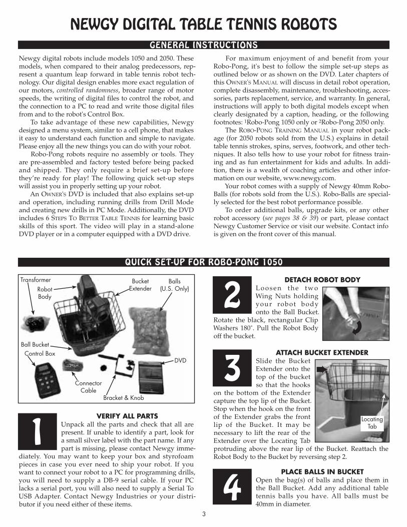
Robo-Pong robots require no assembly or tools. They are pre-assembled and factory tested before being packed and shipped. They only require a brief set-up before they’re ready for play! The following quick set-up steps will assist you in properly setting up your robot.
An Owner's DVD is included that also explains set-up and operation, including running drills from Drill Mode and creating new drills in PC Mode. Additionally, the DVD includes 6 steps tO Better taBle tennis for learning basic skills of this sport. The video will play in a stand-alone DVD player or in a computer equipped with a DVD drive.
For maximum enjoyment of and benefit from your Robo-Pong, it's best to follow the simple set-up steps as outlined below or as shown on the DVD. Later chapters of this Owner's Manual will discuss in detail robot operation, complete disassembly, maintenance, troubleshooting, acces-sories, parts replacement, service, and warranty. In general, instructions will apply to both digital models except when clearly designated by a caption, heading, or the following footnotes: 1Robo-Pong 1050 only or 2Robo-Pong 2050 only.
The rOBO-pOng training Manual in your robot pack-age (for 2050 robots sold from the U.S.) explains in detail table tennis strokes, spins, serves, footwork, and other tech-niques. It also tells how to use your robot for fitness train-ing and as fun entertainment for kids and adults. In addi-tion, there is a wealth of coaching articles and other infor-mation on our website, www.newgy.com.
Your robot comes with a supply of Newgy 40mm Robo-Balls (for robots sold from the U.S.). Robo-Balls are special-ly selected for the best robot performance possible.
To order additional balls, upgrade kits, or any other robot accessory (see pages 38 & 39) or part, please contact Newgy Customer Service or visit our website. Contact info is given on the front cover of this manual.
verify all partsUnpack all the parts and check that all are present. If unable to identify a part, look for a small silver label with the part name. If any part is missing, please contact Newgy imme-
diately. You may want to keep your box and styrofoam pieces in case you ever need to ship your robot. If you want to connect your robot to a PC for programming drills, you will need to supply a DB-9 serial cable. If your PC lacks a serial port, you will also need to supply a Serial To USB Adapter. Contact Newgy Industries or your distri-butor if you need either of these items.
attach Bucket extenderSlide the Bucket Extender onto the top of the bucket so that the hooks
on the bottom of the Extender capture the top lip of the Bucket. Stop when the hook on the front of the Extender grabs the front lip of the Bucket. It may be necessary to lift the rear of the Extender over the Locating Tab protruding above the rear lip of the Bucket. Reattach the Robot Body to the Bucket by reversing step 2.
Newgy DIgITAL TAbLe TeNNIs RoboTs
QuIck seT-uP foR Robo-PoNg 1050
geNeRAL INsTRucTIoNs
3
RobotBody
LocatingTab
BucketExtender
Transformer Balls(U.S. Only)
DVDControl Box
ConnectorCable
Ball Bucket
1
3
detach rOBOt BOdyL o o s e n t h e t w o Wing Nuts holding your robot body onto the Ball Bucket.
Ro tate the black, rectangular Clip Washers 180˚. Pull the Robot Body off the bucket.
2
➨
place Balls in BucketOpen the bag(s) of balls and place them in the Ball Bucket. Add any additional table tennis balls you have. All balls must be 40mm in diameter.
4
Bracket & Knob

4
adjust head angleTi l t t h e h e a d down ward as far as possible. If the head won't move,
loosen the brass knob and then re-tighten after moving head. Veri fy that the word “topspin” is at the top of the ball discharge hole. (See Figures 3, 4, & 6 on pages 15 and 16 for more info.)
pOsitiOn rOBOt On taBlePosition the robot in the center of the table close to the end line as shown.
The robot’s head should be in line with the centerline of the table (Robot position 1, Figure 12, page 18).
6cOnnect caBle tO rOBOt
Plug one end of the Connector Cable into the 5-Pin Connector on the back of the robot as
shown. (Also see Figure 14, page 19.) Take the other end of the cable to the player's end of the table.
5
7➨
➨
cOnnect caBles tO cOntrOl BOxBring the free end of the Connector Cable to the pla-yer ’s end of the
table. Plug the Connector Cable into the 5-pin socket on the bot-tom of the Control Box. Then insert the Transformer’s pin into the Power Jack of the Control Box (see Figure 1B, page 6). If you want to hook up a PC to the Control Box, connect the male end of a DB-9 serial cable (user supplied) to the female serial port of the Control Box.
attach Bracket tO cOntrOl BOxTurn Control Box upside down on the table. Take the Mounting Bracket
and align the hole in the mount-ing arm with the threaded insert of the Control Box. Secure bracket with Mounting Screw. Leave Control Box laying face down.
adjust Bracket tO tOp thicknessPick up the Control Box and looking across the
round rubber pad of the Adjustment Screw, raise or lower the height of the rubber pad so it aligns with the nearest mark on the bracket's label that corresponds with the thickness of your table's top.
plug serial caBle intO pcIf you want to hook up your robot to a PC (optional), con-
nect the female end of a serial cable to an open male DB-9 port of your PC. If your computer lacks a serial port, plug the female end of the serial cable into the male DB-9 end of a Serial To USB Adapter. Lastly, plug the male USB connector of the adap-ter into an open USB port of the PC. Follow the instruc-tions that came with your adapter to install the adapter's driver into your operating system.
attach cOntrOl BOx tO taBleAngle the o p e n i n g b e t w e e n t h e t w o
ru b b e r p a d s o f t h e M o u n t i n g B r a c k e t towards the bot tom of your table's apron. Slip the bracket onto the table. The rectangular rubber pad of the bracket should sit flat on the table's top surface. If it is not flat, loosen or tighten the Adjustment Screw until the pad lays flat. This is not a clamping mechanism—do not overtighten!
pOsitiOn yOur cOntrOl BOxPlace the Control Box on the side of the table about one foot from the end. If
you're right-handed, place it on the left side of the table. If you're left-handed, place it on the right side. (See Figure 12, page 18). Plug the Transformer into any standard electrical socket.
10
13
11
12
9
8get ready tO play!
If not already on, turn the Control Box on by pressing the Power button (see page 6). Adjust the Ball Speed to 8 by pressing the + button. Pick up your paddle and press the
Stop/Start button. The balls will start loading into the robot. It takes about 15 seconds before the first ball is shot out. It will be delivered down the centerline of the table with Topspin. To become more familiar with the controls and adjustments for your machine, read the OperatiOn sec-tion of this manual starting on page 6.
14➨

pull dOwn suppOrt legsPlace the robot on the table with the open front side facing you. Pull the curved black
metal support legs toward you.
5
spread suppOrt legs apartSpread out the sup-port legs to their fully open position.
jOin net suppOrt tuBesTu r n t h e r o b o t around 180° so the Net Support Tubes are now facing you.
Grasp the second tube from your right and pull up, removing it from its storage hole. Place the bottom of this tube into the top of the first tube on your right as shown. Repeat on the left side.
2
3
4
lOwer Ball traysGrasp one of the Ball Return Trays, lift straight up to unlock it, grasp the adjacent Net Support Tube, and slowly lower them into position. Be careful not to let the tray or
support tube slam down. Repeat on the other side.
5
Support Legs
Joining Net Support Tubes
attach rOBOt tO taBlePick up the robot by the bottom of the Center Trough and secure it to the table by angling it downward and pushing it onto the end of the table. The Support Legs go underneath
the table and the Front Support Plate sits on top of the table. The center of the Front Support Plate aligns with the centerline of the table. The robot will be held by its own weight. (See Figure 13, page 19 for more detail.)
6
➨
➨
➨
➨
➨
QuIck seT-uP foR Robo-PoNg 2050
Robot Body& Net
Assembly
Transformer
Bracket & Knob
Balls(U.S. Only)
ControlBox
ConnectorCable
TrainingManual
(U.S. Only)
RubberTips
DVD
verify all partsUnpack all the parts and check that all are present. If unable to identify a part, look for a small silver label with the part name. If a part is missing, please contact Newgy. You
may want to keep your box and styrofoam pieces in case you need to ship your robot. If you purchased Pong-Master, check the photo below to verify all of its parts. In your Owner ’s Packet is a separate Ow n e r’s Ma n u a l for Pong-Master. That manual will tell you how to set up and operate Pong-Master. To help you separate robot parts from Pong-Master parts, the silver labels have “RP” before the part names for the robot and a “PM” before the part names for Pong-Master.
1
coNTRoL boX feATuRes (ALL moDeLs)
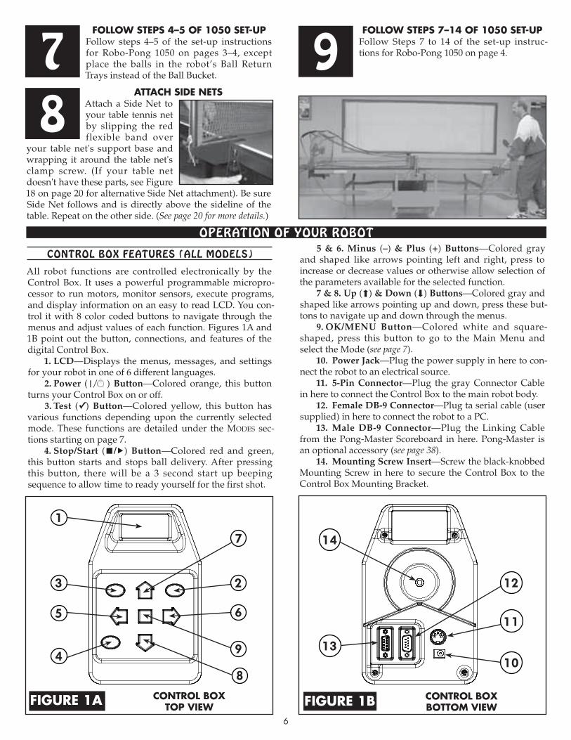
All robot functions are controlled electronically by the Control Box. It uses a powerful programmable micropro-cessor to run motors, monitor sensors, execute programs, and display information on an easy to read LCD. You con-trol it with 8 color coded buttons to navigate through the menus and adjust values of each function. Figures 1A and 1B point out the button, connections, and features of the digital Control Box.
1. LCD—Displays the menus, messages, and settings for your robot in one of 6 different languages.
2. Power (|/ ) Button—Colored orange, this button turns your Control Box on or off.
3. Test (✓) Button—Colored yellow, this button has various functions depending upon the currently selected mode. These functions are detailed under the MODes sec-tions starting on page 7.
4. Stop/Start (■/▶) Button—Colored red and green, this button starts and stops ball delivery. After pressing this button, there will be a 3 second start up beeping sequence to allow time to ready yourself for the first shot.
5 & 6. Minus (–) & Plus (+) Buttons—Colored gray and shaped like arrows pointing left and right, press to increase or decrease values or otherwise allow selection of the parameters available for the selected function.
7 & 8. Up (⬆) & Down (⬇) Buttons—Colored gray and shaped like arrows pointing up and down, press these but-tons to navigate up and down through the menus.
9. OK/MENU Button—Colored white and square-shaped, press this button to go to the Main Menu and select the Mode (see page 7).
10. Power Jack—Plug the power supply in here to con-nect the robot to an electrical source.
11. 5-Pin Connector—Plug the gray Connector Cable in here to connect the Control Box to the main robot body.
12. Female DB-9 Connector—Plug ta serial cable (user supplied) in here to connect the robot to a PC.
13. Male DB-9 Connector—Plug the Linking Cable from the Pong-Master Scoreboard in here. Pong-Master is an optional accessory (see page 38).
14. Mounting Screw Insert—Screw the black-knobbed Mounting Screw in here to secure the Control Box to the Control Box Mounting Bracket.
6
attach side netsAttach a Side Net to your table tennis net by slipping the red flexible band over
your table net's support base and wrapping it around the table net's clamp screw. (If your table net doesn't have these parts, see Figure 18 on page 20 for alternative Side Net attachment). Be sure Side Net follows and is directly above the sideline of the table. Repeat on the other side. (See page 20 for more details.)
8
fOllOw steps 4–5 Of 1050 set-upFollow steps 4–5 of the set-up instructions for Robo-Pong 1050 on pages 3–4, except place the balls in the robot’s Ball Return Trays instead of the Ball Bucket.
7fOllOw steps 7–14 Of 1050 set-up
Follow Steps 7 to 14 of the set-up instruc-tions for Robo-Pong 1050 on page 4.9
oPeRATIoN of youR RoboT
cOntrOl BOxtOp viewfigure 1a
1
23
4
5 6
7
8
910
11
12
13
14
cOntrOl BOxBOttOm viewfigure 1B
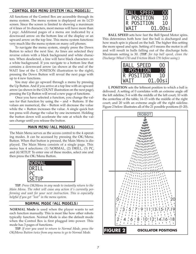
BALL SPEED 00L POSITION 10R POSITION 10WAIT 01.00s
BALL SPEED sets how fast the Ball Speed Motor spins. This determines both how fast the ball is discharged and how much spin is placed on the ball. The higher this setting the more speed and spin. Setting of 0 means the motor is off and will result in balls falling out of the discharge hole. Maximum setting is 30. (TIP: for top ball speed, clean the Discharge Wheel (78) and Friction Block (79) before using.)
BALL SPEED 00L POSITION 10R POSITION 10WAIT 01.00s
L POSITION sets the leftmost position to which a ball is delivered. A setting of 0 correlates with an extreme angle off the left sideline; 5–6 with the middle of the left court; 10 with the centerline of the table; 14–15 with the middle of the right court; and 20 with an extreme angle off the right sideline. Figure 2 below illustrates all of the 21 possible positions (0–20).
200
108 126 144 162 18
97 115 133 151 17 19
7
OscillatOr pOsitiOnsfigure 2
coNTRoL boX meNu sysTem (ALL moDeLs)
All functions of the Control Box are accessible through its menu system. The menu system is displayed on its LCD screen. Since the screen is limited to showing a maximum of 4 lines of 16 characters, most menus will have more than 1 page. Additional pages of a menu are indicated by a downward arrow on the bottom line of the display or an upward arrow on the top line. This menu system functions very much like the menu system on many cell phones.
To navigate the menu system, simply press the Down Button to select the next line. As lines are selected they reverse colors with a black background and white charac-ters. When deselected, a line will have black characters on a white background. If you navigate to a bottom line that contains a downward arrow (as shown at the end of the WAIT line of the L POSITION illustration to the right), pressing the Down Button will reveal the next page with up to 4 new functions.
You may also go upward through a menu by pressing the Up Button. And if you arrive at a top line with an upward arrow (as shown in the COUNT illustration on the next page), pressing the Up Button will reveal a new page of functions.
Once you have selected a function, you change the val-ues for that function by using the – and + Buttons. If the values are numerical, the – Button will decrease the value while the + Button increases the value. A single quick but-ton press will change the value by one increment. Holding the button down will accelerate the rate at which the val-ues change until you release the button.
mAIN meNu (ALL moDeLs)
The Main Menu serves as the access control to the 4 operat-ing modes. It can be accessed by pressing the OK/Menu Button. When that button is pressed, the Main Menu is dis-played. The Main Menu consists of a single page. This menu has 4 selections: (1) NORMAL, (2) DRILL, (3) PC, and (4) SETUP. To enter one of these modes, select one and then press the OK/Menu Button.
NORMALDRILLPCSETUP
TIP: Press OK/Menu in any mode to instantly return to the Main Menu. The robot will cease any action it's currently per-forming and wait for your next instruction. This is especially helpful if you get "lost" in the menu system.
NoRmAL moDe (ALL moDeLs)
NORMAL Mode is used when the player wants to set each function manually. This is most like how other robots typically function. Normal Mode is also the default mode when the Control Box is first plugged into power. This mode has 3 pages of functions.
TIP: If ever you want to return to Normal Mode, press the OK/Menu Button twice from any menu to go to Normal Mode.

8
A position setting is really a line of direction coming from the robot. Selecting a position number results in a ball being thrown somewhere along the dotted line that corre-sponds with the number. The Head Angle, Ball Speed, and Spin determine where a ball is delivered along that line.
If the robot is not positioned at the center of the endline, these trajectories will change accordingly. See pOsitiOning YOur rOBOt & COntrOls on page 18 for more info.
When L POSITION is set, it automatically sets R POSITION. If both positions are the same, the ball will be thrown to only one position. If L POSITION and R POSITION are different, then the ball is alternately thrown first to the L POSITION and then to the R POSITION.
BALL SPEED 00L POSITION 10R POSITION 10WAIT 01.00s
R POSITION sets the rightmost position to which a ball is delivered. This setting can be changed without affect-ing the L POSITION. However, if L POSITION is changed, R POSITION will need to be reset. Remember, when L & R settings are the same, balls are delivered to only one posi-tion. When they are different, balls are delivered alternately between two positions.
BALL SPEED 00L POSITION 10R POSITION 10WAIT 01.00s
WAIT is the amount of time (interval) between one shot and the next shot in seconds. An easy way to remember this setting is to think, "How long do I want to wait before the next shot?" If the pace seems too slow and you want to wait less, decrease WAIT and ball delivery becomes more rapid. If the pace is too fast and you want to wait more, increase WAIT and ball delivery will slow down.
WAIT can be changed in 0.05 second increments from 0.35 to 50 seconds. However, the minimum setting is dyna-mically linked to L POSITION and R POSITION settings. The larger the difference between L and R, the longer the robot must wait before delivering the next ball. This is because it takes a minimum amount of time for the robot to change positions. For every difference of 2 in the settings between L & R, another 0.05 is added to WAIT.
For example, if L & R are both set to 5 (no oscillation), the minimum WAIT is 0.35 seconds. But if L is set to 0 and R to 20 (a difference of 20), 0.50 is added to the minimum WAIT to allow time for the robot's head to sweep from the far left sideline to the far right sideline. In this example, the mini-mum WAIT would change from 0.35 to 0.85 seconds with a difference of 20 in L & R positions. This ensures that a ball is not shot out until the robot has swept to the correct position.
Please be aware that WAIT is not absolute. This setting may vary a little due to a number of factors, but in general, it is accurate to within ±10%. WAIT also is involved in the calculations for TIME (explained after COUNT).
COUNT 0000TIME 0:00:00OSC RANDOM OFFSPEED RANDOM 00
COUNT indicates the number of balls that the robot delivers before it stops automatically. If COUNT is set to 0, COUNT is ignored and the robot will keep throwing balls until the Stop/Start Button is pressed.
If COUNT is more than 0, it will decrement by 1 every time a ball is thrown until it reaches 0. If Stop/Start Button is pressed before COUNT reaches 0, delivery will stop. Pressing the Stop/Start button a second time will resume the COUNT where it was when it was stopped. Once COUNT reaches 0, it must be reset to a new number before it becomes active.
COUNT is synced with TIME (discussed next). As COUNT is changed, TIME dynamically changes to reflect a multiplication of COUNT times WAIT. For example, with WAIT set to 1 second and COUNT to 61, TIME would show 0:01:01 (1 minute, 1 second).
COUNT 0000TIME 0:00:00OSC RANDOM OFFSPEED RANDOM 00
TIME shows how long the robot will continue throw-ing balls until it stops automatically. TIME is displayed in HR:MIN:SEC format. A display of 1:01:01 indicates 1 hour, 1 minute, and 1 second.
TIME is restricted to increments of WAIT rounded to the next second. For example, if WAIT is 1.50 seconds and TIME is set to 0:00:03, COUNT would show 2. If TIME is set to 0:01:30, COUNT would show 60. However, TIME cannot be set to something like 0:00:05 because that time is not an even increment of WAIT.
TIME is similar to COUNT—a setting of 0 deactivates this function and more than 0 causes the robot to keep run-ning until the value becomes 0. Interrupting TIME by press-ing the Stop/Start Button simply pauses the countdown until the Stop/Start Button is pressed a second time.
Having TIME and COUNT dynamically linked together makes it easy to regulate your training routine by number of balls thrown or by overall time. If you're used to doing a par-ticular routine for 100 balls, set COUNT to 100 and the robot automatically calculates the time it takes to throw 100 balls. If you prefer to regulate your workouts by time, set TIME to 0:03:00, for example, to do your routine for 3 minutes before the robot stops automatically. If you don't want to use TIME or COUNT to stop ball delivery, set them to 0 and you can con-trol ball delivery manually by pressing the Stop/Start button.
TIP: Since TIME and COUNT can be set to very high num-bers, there is a trick to greatly speed up the rate at which the value changes. Press and hold the – or + Button and then press the OK/Menu Button. Values will change much more rapidly.

9
COUNT 0000TIME 0:00:00OSC RANDOM OFFSPEED RANDOM 00
OSC RANDOM turns the oscillator randomization fea-ture on and off. It requires L POSITION and R POSITION to be set to different numbers for it to have any effect. When off, balls are thrown alternately to the left and right positions. When on, balls are thrown randomly between the left and right positions.
For example, if L POSITION is 5, R POSITION is 10, and OSC RANDOM is OFF, balls are delivered alternately to posi-tions 5 and 10. However, if OSC RANDOM is changed to ON, then balls will be placed anywhere between positions 5 and 10; i.e., positions 5, 6, 7, 8, 9, or 10. The robot will pick one of these numbers and throw a ball to the position it chooses.
COUNT 0000TIME 0:00:00OSC RANDOM OFFSPEED RANDOM 00
SPEED RANDOM varies the BALL SPEED so balls are thrown to different depths on the table. The value entered is added to the value for BALL SPEED to give a range of numbers from which the robot can randomly pick.
For example, BALL SPEED is set to 12 and SPEED RANDOM is set to 6. This gives a range of ball speeds from 12 (very short, close to the net) to 18 (very deep, close to the endline). The robot will randomly pick a number from within this range—12, 13, 14, 15, 16, 17, or 18—and throw a ball at that speed.
A value of 00 means no randomization. Maxi mum value is 10. Be cautious about using too high of a value as it could cause balls to be thrown off the end of the table.
HINT: Set the BALL SPEED to the slowest desired speed first, say 15. Then, without changing the head angle, experiment to see what BALL SPEED setting will throw a ball just past the end of the table, say 19. Subtract 1 from this larger number to find the maximum speed that still lands the ball on the table—in this case, 18. Subtract the slowest ball speed, 15, from this maximum speed, 18, to give the maximum SPEED RANDOM setting—3.
WAIT RANDOM0.00
WAIT RANDOM causes the WAIT setting to vary by a certain amount of time. The entered value is added to the WAIT time to provide a range of time for the interval between two consecutive shots. Like WAIT, this setting can be changed in increments of 0.05 seconds. Maximum WAIT RANDOM is 1.00 seconds. A setting of 0.00 means no ran-domization is added to the wait time.
For example, WAIT is 1.00 seconds and WAIT RANDOM is 0.20. These settings would provide a range of wait times
between 1.00 and 1.20 seconds. The robot could pick any time among the following—1.00, 1.05, 1.10, 1.15, or 1.20 seconds.
Using WAIT RANDOM makes it difficult to develop a rhythm and predict when the next ball will be delivered. This encourages the user to maintain a good ready position between each shot and only move after the ball is shot out from the robot.
Also be aware that the greater the WAIT RANDOM is, the less and less accurate TIME and COUNT become. This is because the amount of time between each ball can no lon-ger be accurately calculated since the interval between each shot is constantly changing.
You can use 1, 2, or all 3 randomization controls at once. Combining them together can make for very unpredictable ball deliveries. It is recommended that you use controlled randomization. Add randomness in small increments only after consistency is attained without randomization. As technique improves, gradually increase the amount of ran-domization to more closely simulate live play.
In Normal Mode, the yellow Test Button is used to give 1 or more balls to test your settings. Press Test once and 1 will appear on screen. After a brief delay, 1 ball will be thrown using the current settings. If you hold the Test Button down, the number shown on screen will keep ad van cing in increments of 1 until you release the button. Then, that number of balls will be thrown.
For testing your settings that use randomization or when L POSITION and R POSITION are set to different numbers, it is recommended to advance the number of test balls to at least 4 or 5. Doing so allows you to see the effect of randomization or ensure that the balls are being accu-rately delivered to the correct locations.
DRILL moDe (ALL moDeLs)
NORMALDRILLPCSETUP
DRILL Mode allows access to the 64 drills that come pre-programmed with your robot. Select Drill Mode by going to the Main Menu, selecting DRILL and pressing OK. There are 2 pages of functions in Drill Mode.
The 64 drills have been carefully selected to offer a variety of drills for all playing levels, and to demonstrate how drills can be created for training footwork, forehand-backhand tran-sitions, serve return, and attack of high balls or backspin balls.
Each drill is diagrammed in the Drill DiagraMs section starting on page 22. It is recommended that you keep these diagrams next to your table tennis table when using Drill Mode to quickly refer to the diagrams and select a drill for training a particular aspect of your game. These diagrams also provide information on what type of shots the player is expected to use during the drill and what spin and head angle settings to use. A blank drills diagram page can be found on the Downloads page of www.newgy.com.
Besides the printed drill diagrams, there is another way to help visualize the landing spots for each ball in a drill. It's called Drill Preview and is activated by pressing

10
the yellow T after selection of a particular drill. You will see a diagram representing your half of the table divided into 15 zones—5 across and 3 deep:
1 2 3 4 5
109876
11 12 13 14 15
Next, a series of dots appears, representing the landing spot of each ball in the drill. A beep sound accompanies each dot as it appears on screen. In the diagram above, the small black square in Zone 7 represents that a ball will be thrown somewhere in Zone 7. This gives you a visual im age of how many balls, where each will be placed, and in what order so that you can prepare to move to those spots.
If no Preview is provided, it probably means that the drill has some randomization involved and the landing spots cannot be accurately shown. For drills without a Preview, consult the drill diagram for info on that drill.
DRILL# 01SPIN TOPHEAD ANGLE 02.0WAIT ADJUS 000%
The first 3 lines of each drill are reserved for settings that are predefined for each drill. Except for selecting anoth-er drill, these values cannot be changed. Press the + Button to select a drill with a higher ID number and the – Button for a lower numbered drill.
Once a drill is selected, you need to verify that the Spin (see page 16) and Head Angle (see page 15) are correctly set before starting a drill. Failure to do so will normally cause the drill to not run correctly and landing spots will be dif-ferent than the way the drill was designed.
Regarding Head Angle, the angle indication mecha-nism is not precise. Therefore, it is recommended that if balls within a drill are not landing in the correct spot, that you first try slightly nudging the head angle either up or down to see if this corrects the problem. For instance, if a drill starts with a short serve, and the serve often hits the net, raise or lower the head angle slightly so that the serve still lands short, but it clears the net without touching it.
DRILL# 01SPIN TOPHEAD ANGLE 02.0WAIT ADJUS 000%
WAIT ADJUS is used to increase or decrease the wait time between each shot. The value can be changed from
-100% to +900% in 10% increments. Since WAIT is adjusted by percentage, even drills that have different WAITS pro-grammed within the drill will still run correctly. Players of many different levels can use the same drill without need-ing to rewrite the drill.
For example, let's say a drill has a WAIT of 1 second between the 1st and 2nd ball and a WAIT of 0.80 seconds between the 2nd and 3rd ball. If WAIT ADJUS is set to +010%, the 1st WAIT would be changed to 1.1 seconds and the sec-ond WAIT to 0.88 seconds. The drill would run slower so the player has more time between each ball.
On the other hand, if WAIT ADJUS is set to -010%, the 1st WAIT is reduced to 0.90 seconds and the 2nd one to 0.72 seconds. This causes the drill to run at a faster pace, reduc-ing the time the player has between every ball.
Except for the 5 Beginner level drills, the drills that come with your Robo-Pong are written to simulate real-time rallies. This means that wait times were selected to closely approximate the actual wait times in a rally between two players. If you are unable to keep up with the pace, add a positive WAIT ADJUS until you can maintain the pace for several minutes. Your goal should be to gradually and sys-tematically decrease the WAIT ADJUS to 0.
And once you can keep pace with a drill in real time, then strive to practice the drill at faster than real time by decreasing WAIT ADJUS to a negative value. By using this principle of progressive overloading, you can train your move-ments to flow smoothly at faster and faster speeds. You will react faster to the ball in actual game rallies and you may start dominating rallies simply because you are quicker than your opponent.
SPEED ADJUST 0# OF REPS 0000TIME 0:00:00
SPEED ADJUST increases or decreases the BALL SPEEDS that are preset in a drill. The values range from -9 to +9. The value is added to the BALL SPEED for each ball in a drill.
For instance, a drill has 2 balls in it, one with a BALL SPEED of 14 and the other, 16. If SPEED ADJUST is set to +2, the speed of the 1st ball changes to 16 and the 2nd ball to 18. If set to -2, 1st ball changes to 12 and the second to 14.
SPEED ADJUST should be used sparingly, especially on drills that have both short balls and long balls. Adjusting the speed upward on such a drill would likely make the short ball land too deep and the deep ball get thrown off the table. Adjusting the speed downward would likely make the short balls fall into the net and the deep balls land in the middle of the table.
SPEED ADJUST is best used for drills having a single BALL SPEED. These drills have all balls landing at the same depth on the table. Check Preview (see beginning of page 10) to see if all balls in a drill are thrown at the same depth. Decrease SPEED ADJUST to make balls land shorter on the table and increase it to get deeper balls.
SPEED ADJUST is also handy when used in conjunc-tion with Head Angle. If the specified Head Angle results in a ball that has a higher trajectory than you prefer, simply lower the Head Angle and use a positive SPEED ADJUST to have the ball land at the desired depth on the table. Again, this works best on drills that have a consistent BALL SPEED set for the entire drill.

11
SPEED ADJUST 0# OF REPS 0000TIME 0:00:00
# OF REPS is similar to COUNT of Normal Mode. It automatically stops ball delivery after the specified number of drill repetitions are completed. For instance, if set to 5, and there are 3 balls in the drill, the robot would run the drill 5 times (15 balls total) before stopping. Also a setting of 0 deactivates this function and drills can only be stopped by manually pressing the Stop/Start Button.
If a drill is paused (by pressing the Stop/Start Button), before # OF REPS equals 0, the drill will resume at the start of the repetition at which it was paused when the STOP/START button is pressed again. For example, # OF REPS is set to 5 and the drill is paused in the middle of the 3rd rep. When resumed, the drill would repeat the 3rd repetition since it did not completely finish when interrupted.
SPEED ADJUST 0# OF REPS 0000TIME 0:00:00
TIME stops a drill automatically after the specified amount of time has elapsed. Like Normal Mode, where TIME is dynamically linked to COUNT, in Drill Mode TIME is dynamically linked to # OF REPS. You can increase or decrease TIME in increments of the estimated time it takes to complete 1 full repetition of a drill.
For example, if it takes approximately 5 seconds to complete 1 repetition of a drill, TIME would go up and down in increments of 5 seconds. If a drill contains variable WAIT times, this approximation will become less precise.
Also see TIME (for Normal Mode) on page 8 for further explanation of this function.
Pc moDe (ALL moDeLs)
NORMALDRILLPCSETUP
PC Mode is used whenever you want to connect your Robo-Pong to your Windows® PC to read drills from or write them to the Control Box and to run drills directly from the PC. This Mode consists of a single page:
PC MODEMAKE CONNECTIONTO PCRUN ROBO-SOFT
After seeing this screen, please verify that your PC is connected properly via the serial port on the bottom on the Control Box. This connection routine is discussed in more
detail on page 28. After making the connection, start up your PC and then launch the Robo-Soft program that can be found on the Owner's DVD of your Robo-Pong, or downloaded from Newgy.com.
After Robo-Soft is launched, it takes several seconds to establish communications with the Control Box (be patient). Once located and the launch routine completes, it confirms the connection by displaying a message at the bottom of the program's main window. At the same time, the Control Box confirms a successful connection by displaying a check mark in the lower right corner of the LCD screen:
PC MODEMAKE CONNECTIONTO PCRUN ROBO-SOFT
Once the connection is confirmed at both ends, Robo-Soft can be used to read from and write to the Control Box, and run drills direct from your PC. If you switch out of PC Mode after connecting, the check mark will disappear and you'll need to reestablish communication once you return to PC Mode by using the AutoConnect command. Please read the rOBO-sOft section (page 28) for more info.
Please be aware that a connection between your PC and the Control Box does not need to be established if you only want to open, work on, or save drills stored on your comput-er's hard drive (or external drive connected to your comput-er). A connection is only necessary whenever you desire to communicate with the Control Box via Robo-Soft.
The yellow Test Button does not have any function associated with PC Mode.
seTuP moDe (ALL moDeLs)
NORMALDRILLPCSETUP
SETUP Mode provides access to a variety of calibration routines, user interface settings, and personal preferences. It consists of 2 pages. We recommend that you write these settings down. When you update the firmware or restore factory defaults, these settings will be erased. Writing them down will save time if you need to re-enter the values.
CONTRAST 15HAND RIGHTLANGUAGE ENOSC CALIB 25
CONTRAST adjusts the contrast of the screen to im prove visibility under a variety of lighting conditions. The range is from 00 to 30. Default setting is 15, which should work best for most lighting conditions. However, if so desired, the user can lighten or darken the screen by changing the value. Going down in value provides a lighter screen; whereas, going up in value darkens the screen.

12
If this setting is changed to either extreme value, it may appear that the screen is completely dark or that no infor-mation is displayed. But by adjusting your viewing angle and/or the amount of light hitting the screen, you may see feint outlines of letters and/or numbers. Adjust the value accordingly to make the screen more readable.
CONTRAST 15HAND RIGHTLANGUAGE ENOSC CALIB 25
HAND is one of the intelligent features of the new digi-tal Robo-Pong robots. It lets the user select their dominant hand so that drills run correctly with regards to backhand/fore hand strokes. Values are Right (default) or Left. Select the one that matches your dominant playing hand.
Since drills are often written for right-handed players, who are the vast majority of players, this switch allows a left-handed player to use drills written for right-handed players without needing to rewrite the drill. We recom-mend that all drills be written for right-handed players so that this switch works properly.
HAND only affects drills run from either DRILL Mode or directly from your PC in PC Mode. It has no effect on NORMAL Mode.
CONTRAST 15HAND RIGHTLANGUAGE ENOSC CALIB 25
LANGUAGE allows selection of the desired lan guage for displaying the menu system and messages. Values are EN (English), DE (German), FR (French), ES (Spanish), CN (Chinese), or JP (Japanese). EN is the default. After selecting the desired language, any press of another button will activate that language and all information displayed on the LCD screen will be shown in that language.
If the menu system is displayed in a language that can-not be read, another language can be chosen by using the Language Selection Special Function (see page 13).
CONTRAST 15HAND RIGHTLANGUAGE ENOSC CALIB 25
OSC CALIB is used to calibrate a position setting of 10 with the centerline of your table tennis table (see page 7 for explanation of positions). Once position 10 is calibrated to the centerline, all other positions will be properly calibrated as well. Range of values is from 00 to 50. Default is set to 25.
Decreasing the value results in the ball's landing spot shif ting toward the left and increasing the value results in it shifting to the right. To see if your oscillation needs calibrat-ing, set the Spin to Topspin and the Head Angle to 8. Then press the yellow Test Button once.
5 Balls will be shot out from the robot. Care ful ly ob serve the landing spots of these 5 balls in relation to the
centerline. If the balls land in a cluster around the center-line, no adjustment is necessary. However, if the 5 balls cluster con sis tent ly to the right of the centerline, decrease OSC CALIB until the 5 balls cluster around the centerline. Simi larly, increase OSC CALIB if the test balls con sis tently land to the left of the centerline.
It is normal for balls to land slightly to the left or right of the centerline, but of the 5 test balls thrown, there should be roughly equal numbers that are thrown left or right of the centerline. If balls are always thrown either on the cen-terline or to the right, for example, go ahead and decrease OSC CALIB to shift the cluster slightly to the left.
Before changing OSC CALIB, check to be sure the robot is properly centered on the end of the table. The center sup-port rib of the triangular shaped Front Support Plate (Key #5 on page 46) should align with the centerline of the table.
SENSOR CALIB 10ALARM CALIB 10SPEED CALIB 10255 255 255
SENSOR CALIB corrects poor ball feed perfor mance. Be cautious about changing this from the default value un til you have eliminated other causes, discussed below.
The Ball Sensor (Key #40, Figure H on page 45) detects when a ball should be thrown out and is responsible for ac curate ball counting. If your robot begins to throw 2 balls at once, doesn't throw out a ball when it is supposed to, or seems to often hesitate immediately before a ball throw, you may need to calibrate the Ball Sensor.
Values range from 00 to 20 with 10 being the default value. Decreasing the value advances a ball's position in the ball channel so the ball is sensed "earlier". Increasing the value causes the ball to be sensed "later".
You would decrease the value if the robot doesn't throw a ball out when it's supposed to or seems to often hesitate immediately before ball throws. Increase the value if you often get two balls thrown instead of 1 ball.
Before adjusting SENSOR CALIB, please elimi nate other more likely causes. It is normal for an occasional hesi-tation before a ball throw, but this should not happen on regu lar basis. This is caused by the pickup mechanism missing a ball pickup and rapidly accelerating the feed wheel to "make up" for the missed pickup. There will be a slight hesitation before the ball feed mechanism can "catch up" after a missed pickup. Also if the chip loosens from its chip holder, the Ball Sensor will not work.
A common cause of missed ball pickups is that there are not enough balls immediately in front of the ball pickup mecha nism. Add more balls to your robot to prevent this. If several balls are not in contact with the Pickup Fingers (Key #46, Figure I on page 45), they cannot be picked up. This mi mics incorrect ball sensor calibration, but the true cause is simply there are not enough balls for the pickup mecha-nism to work properly or something is preventing balls from rolling down into the pickup mechanism.
Something else that can cause the ball sensor to not sense balls correctly is that the steel lever attached to the sensor does not protrude far enough into the ball channel. The lever needs to protrude far enough into the channel that a ball

cannot pass by it without activating the sensor (you should hear a clicking sound as the lever is depressed). If necessary, carefully bend this lever inward so it detects balls properly.
Undersized balls may also cause this behavior. Please verify that all balls are 40mm in diameter (see page 17 for using a Ball Dam2 to check ball diameters). Robo-Pong 2050 and 1050 cannot utilize 38mm balls.
Lastly, something that causes double ball throws is a broken Ball Discharge Spring (#58, Fig. D, pg. 44). If this part is broken, missing, or deformed, it is likely the culprit and should be replaced before adjusting SENSOR CALIB. Forcing the head angle to less than 1 can also cause this.
If you have eliminated other more likely causes, adjust SENSOR CALIB by setting the head to Backspin and to Angle 7. Then press the yellow Test Button. The robot will begin shooting balls into the table net and the balls will roll back into the net system. If balls aren't being thrown into the table net, adjust the Head Angle until they are.
Balls will be delivered to positions 12 and 16. Watch the head carefully to be sure that one and only one ball is thrown out each time the head completes its sideways trav-el. It likely will take numerous balls to be thrown before a problem is detected. Press any button to stop the test. If SENSOR CALIB needs adjusting, select a new value and then repeat the test until the problem disappears.
SENSOR CALIB 10ALARM CALIB 10SPEED CALIB 10255 255 255
ALARM CALIB effects the sensitivity of the Ball Jam Alarm. This alarm is activated whenever the resistance of the Ball Feed Motor rises above a preset level. This causes the alarm to sound and power to the Ball Feed Motor is cut until the problem is resolved. This prevents damage to the Ball Feed gears and other parts. For most users, this feature will never be needed and should be kept at default value.
Dirty, broken, or oversized balls are the most likely causes for this alarm to activate. Other causes are foreign objects or anything else that would prevent balls from being pushed smoothly through the ball channel.
The alarm has a range of adjustment to allow the user to make it activate sooner or later than "normal". The range is from 0 to 20 with 10 being the default value. If you desire more sensitivity, you can increase the value. If you want less sensitivity, decrease the value.
A likely scenario where you may consider decreasing the sensitivity would be if the balls get very dirty and the alarm starts activating. Instead of stopping and washing the dirt off the balls, the user wants to continue playing with dirty balls. Although not guaranteed, decreasing ALARM CALIB may allow dirty balls to be used until such time that they can be properly cleaned.
SENSOR CALIB 10ALARM CALIB 10SPEED CALIB 10255 255 255
SPEED CALIB is used to fine tune the BALL SPEED. For drills that have been created on a different Robo-Pong to work correctly on your robot, it is important that BALL SPEEDS on the two machines be calibrated so that a value of, for instance 15, results in the same landing spot on both robots. This problem would most likely be caused by com-ponents wearing or aging.
Values range from 0 to 20 with 10 being default value. Increasing the value results in more speed being added to the ball; decreasing the value, in less speed. However, there is an upper limit to this effect—no balls set at BALL SPEED 25 or higher will be affected by SPEED CALIB. So don't think that increasing this value will result in faster top speeds. BALL SPEED 30 is already set at the maximum for the motor and the electronics controlling that motor. So set-ting SPEED CALIB to 20 and using a BALL SPEED of 30 would not result in even more speed being applied to the ball. As a matter of fact, it would cause the robot to run worse, possibly resulting in an over-voltage situation where power is cut off to the Ball Speed Motor.
SPEED CALIB should only be used as a last resort when all other possible solutions do not resolve the prob-lem. The first thing you should check if balls are not land-ing where they should, is to check that the robot is level and the Head Angle is set properly.
As discussed previously, the Head Angle Adjustment Mechanism is not precise, so a Head Angle Setting should be used as a general guideline, not as an absolute. In gener-al, for any given head angle, the acceptable tolerance is ± 0.25. So if the given Head Angle is 8, the acceptable range for that setting is 7.75 to 8.25. Many times, speed "problems" can be resolved simply by adjusting the head angle.
Another common cause of slower ball speeds is that the rubber Discharge Wheel and/or Friction Block are dirty. Dirt buildup on these two parts can cause a substantial reduction in ball speeds. Clean these parts regularly to maintain top speeds. See page 37 for recommended clean-ing procedures.
To use SPEED CALIB, you must make a 6 x 6 inch paper target. One is provided on page 27, but instead of cutting that target out, we recommend making a copy and using the copy. Then follow the instructions as given on the target.
sPecIAL fuNcTIoNs (ALL moDeLs)
There are 4 special functions that can be accessed by press-ing a combination of buttons on the Control Box: (1) Language Selection, (2) Ball Unloading, (3) Self Diagnostics, and (4) Factory Default Restoration. All special functions begin by pressing and holding the OK/Menu Button until the screen goes blank. Release the OK/Menu Button and after a brief moment, the screen turns completely black. Then press one of the gray arrow-shaped buttons as given in the following descriptions:
Language Selection is particularly useful if the menu system is displayed in a language that the user cannot read. Press and hold the OK/Menu Button until the screen goes blank and then release. Momentarily, the screen turns com-pletely black. Now press and hold the Up Button. The fol-lowing message appears in the currently selected language:
13

RELEASE BUTTONWHEN YOU SEEYOUR LANGUAGE
It will then begin cycling through all the languages, one at a time, with a short pause before each one. When you see the language you prefer, let go of the Up Button and the menus will stay in that language. Press any button to exit Special Functions mode and resume normal operations.
Ball Unloading is used when you want to quickly empty balls out of the robot's trays2 or bucket1. This is typi-cally done when the user wants to practice serves by gath-ering all balls from the robot and placing them into a bin.
Before using this function, get a medium-sized plastic bin (available at many department & hardware stores). If you have a Robo-Caddy (see page 39), it's convenient if the plastic bin is sized to fit into the caddy's tray.
Place the plastic bin under the robot's head. Then press and hold the OK/Menu Button until the screen goes blank and then release. After the screen turns completely black, press the Down Button. The following message appears:
BALL UNLOADINGPLACE TRAY UNDERROBOT HEAD
In a moment, balls will start dropping out of the robot's head at maximum frequency, landing in the plastic bin placed underneath. In a short amount of time, all balls will be pulled from the trays2 or bucket1 and deposited into the bin. Place the bin on the top of the table or into the top of the Robo-Caddy on the server's end of the table. Now practice your serves and use the robot's net system to capture and collect your serves:
Self Diagnostics is used to help troubleshoot the robot when having problems with the robot. This should be used principally with a trained service technician who can prop-erly interpret the codes provided. Always perform a Factory Default Restoration (described next) before using Self Diagnostics.
To activate, use the same routine described previously for making the screen go black. Then press the + Button. The screen will display the following message and then generate a series of numbers in the last line:
TESTING SYSTEMGIVE ERROR #STO TECHNICIAN0123456789
Write down these numbers and give them to a service technician. These codes may assist the technician with trou-bleshooting the problem. Also see the trOuBle shOOting sec-tion beginning on page 41.
Factory Default Restoration is handy when you suspect that a setting may be causing the robot to behave in a strange manner. Restoring all settings to factory default means that all values are set back to the default value for each function This is a handy step to take when you suspect that the robot is malfunctioning and should always be done before calling for service help. It may clear up the problem by itself.
Please remember to recalibrate your robot (see pages 12–13) after using Factory Default Restoration as any cus-tom setting is overwritten during this procedure. As men-tioned previously, it is handy to write down all values for functions in the SETUP Mode, so you can quickly reenter them after you use Factory Default Restoration. We have included a space on the back cover to record your settings.
Like the other Special Functions, begin by holding down the OK/Menu button until the screen goes blank and then release that button. When the screen turns all black, press the – Button. You will then see the following screen:
RESTORINGFACTORYDEFAULTS
And after a moment or so, the screen will confirm that the procedure completed successfully:
FACTORYDEFAULTSRESTORED
A few seconds later, the above screen disappears and the system reboots and you are taken automatically to page 1 of the default Normal Mode.
14

bALL TRAjecToRy (ALL moDeLs)
The trajectory of a ball is regulated by adjusting the angle of the robot head. The angle can be changed from low to high. At its lowest setting (1), the ball will be delivered so it first strikes the robot's side of the table, bounces over the net, and lands on the player's side of the table (just like a serve). At its highest setting (13), the ball will be delivered in a high arc over the net (like a lob return).
The trajectory is adjusted by tilting the head up or down. If the head will not tilt, loosen the Brass Knob on the right side of the robot head. If the head does not stay at the desired angle, tighten the Brass Knob slightly (see Figure 3). For reference, there are head angle indicators next to the Brass Knob numbered 1 to 13 (see Figure 4). These
in dica tors are not precise, so you may need to nudge the head slightly up or down from a setting when a particular head angle is provided.
WARNING: Do NoT adjust the head angle when the head is moving side to side. Failure to follow these instructions may result in broken parts and may void your warranty.
BALL SPEED directly influences the ball trajectory set-ting. When the head is set so the ball first strikes the robot's side of the table (robot “serving”—see Figures 5C & 5D), maximum BALL SPEED is approximately 11–13. As BALL SPEED is increased, the head must be angled up to deliver the ball so it first strikes the player's side of the table (robot
“returning”—see Figures 5A & 5B). As BALL SPEED is increased even more, adjust the head angle down to pre-vent the ball from being thrown off the end of the table.
incOrrect rOBOt head angle,rOBOt “returning”figure 5a
head angle indicatOrsfigure 4
cOrrect rOBOt head angle,rOBOt “returning”figure 5B
incOrrect rOBOt head angle,rOBOt servingfigure 5c
cOrrect rOBOt head angle,rOBOt servingfigure 5d
Robot head is tilted too high, resulting in ball being thrown off the end of the table.
Same ball speed as Figure 5A, but now robot head is tilted down so the ball lands on the table.
When robot is set to serve onto its side of table first, and the head angle is too severe, the ball will rebound abnormally high.
Same ball speed as Figure 5C, but head angle has been raised slightly so ball stays low to the net. With robot serving, maximum ball speed is limited to 11-13 before ball is thrown off the end of table.
Robot Head
70Angle Pointer69
Brass Knob
Robot Head
Robot Head
Robot Head
If necessary, loosen knob (69) to adjust angle of head up or down. Tighten knob if head will not stay in position.
adjusting head anglefigure 3
15
Head Angle Indicators
16
bALL sPIN (ALL moDeLs)
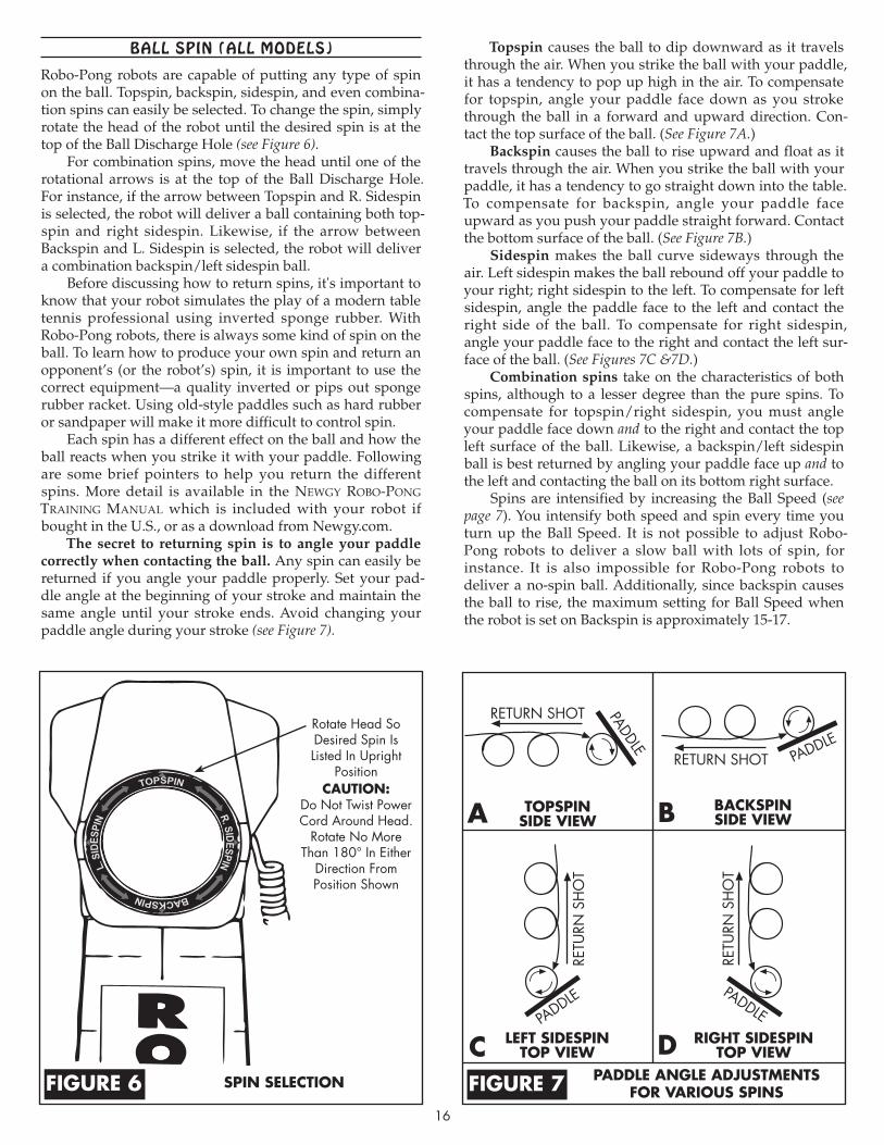
Robo-Pong robots are capable of putting any type of spin on the ball. Topspin, backspin, sidespin, and even combina-tion spins can easily be selected. To change the spin, simply rotate the head of the robot until the desired spin is at the top of the Ball Discharge Hole (see Figure 6).
For combination spins, move the head until one of the rotational arrows is at the top of the Ball Discharge Hole. For instance, if the arrow between Topspin and R. Sidespin is selected, the robot will deliver a ball containing both top-spin and right sidespin. Likewise, if the arrow between Backspin and L. Sidespin is selected, the robot will deliver a combination backspin/left sidespin ball.
Before discussing how to return spins, it's important to know that your robot simulates the play of a modern table tennis professional using inverted sponge rubber. With Robo-Pong robots, there is always some kind of spin on the ball. To learn how to produce your own spin and return an opponent’s (or the robot’s) spin, it is important to use the correct equipment—a quality inverted or pips out sponge rubber racket. Using old-style paddles such as hard rubber or sandpaper will make it more difficult to control spin.
Each spin has a different effect on the ball and how the ball reacts when you strike it with your paddle. Following are some brief pointers to help you return the different spins. More detail is available in the newgY rOBO-pOng training Manual which is included with your robot if bought in the U.S., or as a download from Newgy.com.
The secret to returning spin is to angle your paddle correctly when contacting the ball. Any spin can easily be returned if you angle your paddle properly. Set your pad-dle angle at the beginning of your stroke and maintain the same angle until your stroke ends. Avoid changing your paddle angle during your stroke (see Figure 7).
Topspin causes the ball to dip downward as it travels through the air. When you strike the ball with your paddle, it has a tendency to pop up high in the air. To compensate for topspin, angle your paddle face down as you stroke through the ball in a forward and upward direction. Con-tact the top surface of the ball. (See Figure 7A.)
Backspin causes the ball to rise upward and float as it travels through the air. When you strike the ball with your paddle, it has a tendency to go straight down into the table. To compensate for backspin, angle your paddle face up ward as you push your paddle straight forward. Contact the bottom surface of the ball. (See Figure 7B.)
Sidespin makes the ball curve sideways through the air. Left sidespin makes the ball rebound off your paddle to your right; right sidespin to the left. To compensate for left sidespin, angle the paddle face to the left and contact the right side of the ball. To compensate for right sidespin, angle your paddle face to the right and contact the left sur-face of the ball. (See Figures 7C &7D.)
Combination spins take on the characteristics of both spins, although to a lesser degree than the pure spins. To compensate for topspin/right sidespin, you must angle your paddle face down and to the right and contact the top left surface of the ball. Likewise, a backspin/left sidespin ball is best returned by angling your paddle face up and to the left and contacting the ball on its bottom right surface.
Spins are intensified by increasing the Ball Speed (see page 7). You intensify both speed and spin every time you turn up the Ball Speed. It is not possible to adjust Robo-Pong robots to deliver a slow ball with lots of spin, for instance. It is also impossible for Robo-Pong robots to deliver a no-spin ball. Additionally, since backspin causes the ball to rise, the maximum setting for Ball Speed when the robot is set on Backspin is approximately 15-17.
Rotate Head So Desired Spin Is Listed In Upright
PositioncautiOn:
Do Not Twist Power Cord Around Head.
Rotate No More Than 180° In Either
Direction From Position Shown
spin selectiOnfigure 6
TOPSPINSIDE VIEW
BACKSPINSIDE VIEW
PADDLE
PADDLE
LEFT SIDESPINTOP VIEW
RIGHT SIDESPINTOP VIEW
RETURN SHOT
RETU
RN S
HO
T
RETURN SHOT
PADDLE PADDLE
RETU
RN S
HO
T
paddle angle adjustmentsfOr variOus spinsfigure 7
a B
c d

17
bALL DAms (2050 oNLy)
Robo-Pong 2050 comes with a pair of Ball Dams. They serve three functions: (1) they keep balls inside the Center Trough when the robot is folded up, (2) they keep balls from entering the Center Trough when you want to remove the robot body, and (3) they serve as a ball gauge for determining if a ball is the proper size and whether it should be used in the robot.
The Ball Dams, when used for functions 1 or 2, fit into two retaining slots at the top of the Center Trough. When not in use, the Ball Dams fit into their storage slots on the side of the Center Trough (see Figure 8).
To use the Ball Dams when preparing the robot for stor-age or transport, remove the Ball Dams from their storage slots by pulling slightly up on the trays to reveal the storage slots (see Figure 10). Then push all the balls into the Center Trough and insert the Ball Dams into their retaining slots (see Figure 9). To use the Ball Dams for function #2, push the balls up into one of the Ball Return Trays and quickly insert the Ball Dam into its retaining slot before the balls can roll down into the Center Trough. The balls will be out of the way and you can easily loosen the two wing nuts and two clip washers, then pull up on the robot body to remove it.
The hole in a Ball Dam serves as a handy ball checking feature. The hole is exactly 40mm in diameter. Robo-Pong 1050 and 2050 can use only 40mm balls. Do not use 38mm, 44mm, or any other ball size than 40mm. Use the hole to test the roundness and size of balls used in the robot.
If you suspect a ball is out of round or too large, as indicated by balls jamming within the robot, insert the sus-pected ball into the ball checker hole. With your fingers, rotate it around inside the hole to check all possible diame-ters of the ball. The ball should have equal clearance through the hole on all diameters. The ball should barely fit through the hole without binding. It is also possible that a ball is too small. In this case, you will notice a considerable gap between the ball and the edge of the hole.
Ball DamRetainer Slot
Ball DamStorage Slot
Ball Checker
Hole
15Ball Dam
1Center Trough
Ball dam & center trOugh(2050 Only)figure 8
inserting Ball dam(2050 Only)figure 9
remOving Ball dam(2050 Only)figure 10
checking Ball with Ball dam(2050 Only)figure 11
➥
➨
➨
Rotate Ball Inside Hole To Check All Diameters Of The Ball. Ball Should
Pass Easily Through Hole On All Diameters.

PosITIoNINg youR RoboT AND coNTRoLs (ALL moDeLs)Robo-Pong robots are versatile in how they are posi tioned in relation to the table. The 1050 nor mally sits on top of the table as shown in robot positions 1–4 in Figure 12. They can also be mounted in the optional Robo-Caddy (see page 39) and placed behind the table like positions 5 & 6. The 2050 is typically mounted to the end of the table at position 5, but can alterna-tively be mounted in the Robo-Caddy just like the 1050.
Some positions offer certain advantages while other positions compromise some of the robot’s functions. By placing the robot in various positions you can achieve a variety of angles and trajectories to simulate almost any type of shot you would encounter in a regular game. The following paragraphs explain this further.
Position 1—Robot positioned square to the table where the centerline and endline of the table meet. This is the only
“on the table” position in which the 1050’s oscillator posi-tions will be accurate (see Figure 2, page 7). Also, this is the desired starting position when first setting up the 1050.
Position 2—Robot positioned at the far left corner and angled cross-court. This position will skew the 1050’s oscil-lator positions toward the player’s right side of the table. This position would be the preferred direction when simu-lating typical right-handers’ forehand to forehand rallies.
Position 3—Robot positioned at the far right corner and angled cross-court. Setting the robot in this position will skew the 1050’s oscillator positions toward the player’s left side of the table. Typical backhand to backhand play for right-hand-ers would be ideally simulated with the robot in this position.
Position 4—A robot placed in this position has the advantage of offering slower and faster ball speeds be cause it is closer to the landing spot of the ball. At a Ball Speed setting of 1, the ball is very slow and with light spin, but is delivered deep on the player’s end. At a Ball Speed setting of 30, the ball speed is very fast and simulates the angle from which a typical kill shot would be hit. However, the 1050’s oscillator range is narrower than if the robot had been positioned at the endline like Positions 1–3. This posi-tion also is similar to the ball release point that most coach-es use when doing multi-ball drills with a student.
Position 5—This is the normal position of the 2050 when it is attached to the end of the table, and its net system would function normally. The 1050 would have to be mount-ed in the Robo-Caddy to be in this position. Positioned here, the 2050’s and 1050’s oscillator ranges would be accurate.
Position 6—Mounted in a Robo-Caddy, both models can be freely moved around in back of the table. The Robo-Caddy also permits lowering or raising the height of the robot. This is great for simulating deep shots such as chops, lobs and loops. However, the oscillator ranges for the 1050 and 2050 are not accurate and the 2050’s net system is usu-ally not effective at capturing balls when in this position. Additionally, you need to purchase a Shielded Connector Extension Cable to extend the length of the Connector Cable from 11 to 22 feet. This permits the Control Box to stay within reach of the player.
RobotPos. 1Robot
Pos. 2RobotPos. 3
RobotPos. 4
RobotPos. 5
Robot Pos. 6
Right HandPlayer
Left HandPlayer
Control Box
A B
These positions are only a few of the ones possible, but they will give you a good idea of the pluses and minuses of placing the robot in a particular position.
IMPORTANT NOTE: Even though the oscillator range may not be accurate as described in Figure 2 on page 7 when the robot is in certain positions, you should be able, with experimen-tation, to find the correct settings to permit ball delivery over any particular part of the table.
Figure 12 also illustrates the ideal positions for the Control Box. If you’re right-handed, Position A is the pre-ferred location for the controls. If you’re left-handed, Position B is preferred. Locating the controls in these sug-gested positions permits the controls to stay within easy reach of the player’s free hand.
Since a player has a longer reach on the forehand side, it is suggested that you position your body as shown. The overwhelming majority of tournament level players use their backhand to cover about one-third of the table and their forehand to cover the other two-thirds of the table.
rOBOt and cOntrOl BOxpOsitiOnsfigure 12
18
LeveLINg ADjusTmeNT (2050 oNLy)
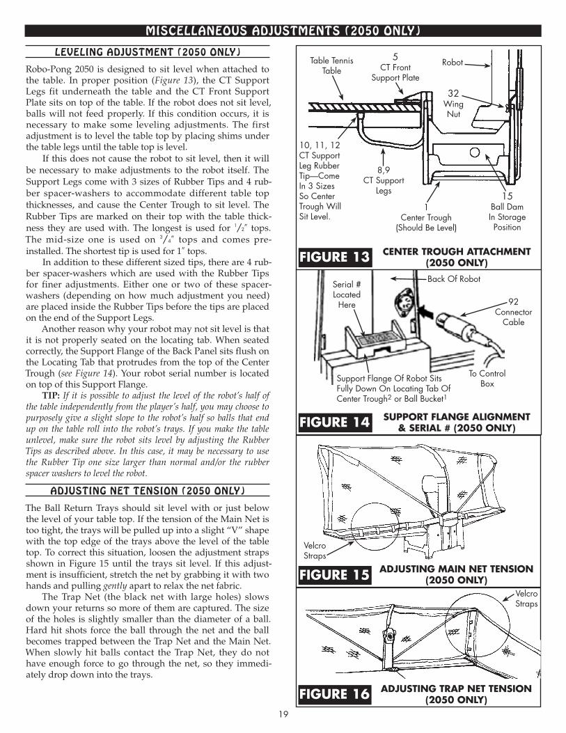
Robo-Pong 2050 is designed to sit level when attached to the table. In proper position (Figure 13), the CT Support Legs fit underneath the table and the CT Front Support Plate sits on top of the table. If the robot does not sit level, balls will not feed properly. If this condition occurs, it is necessary to make some leveling adjustments. The first adjustment is to level the table top by placing shims under the table legs until the table top is level.
If this does not cause the robot to sit level, then it will be necessary to make adjustments to the robot itself. The Support Legs come with 3 sizes of Rubber Tips and 4 rub-ber spacer-washers to accommodate different table top thicknesses, and cause the Center Trough to sit level. The Rubber Tips are marked on their top with the table thick-ness they are used with. The longest is used for 1/2″ tops. The mid-size one is used on 3/4″ tops and comes pre-installed. The shortest tip is used for 1″ tops.
In addition to these different sized tips, there are 4 rub-ber spacer-washers which are used with the Rubber Tips for finer adjustments. Either one or two of these spacer-washers (depending on how much adjustment you need) are placed inside the Rubber Tips before the tips are placed on the end of the Support Legs.
Another reason why your robot may not sit level is that it is not properly seated on the locating tab. When seated correctly, the Support Flange of the Back Panel sits flush on the Locating Tab that protrudes from the top of the Center Trough (see Figure 14). Your robot serial number is located on top of this Support Flange.
TIP: If it is possible to adjust the level of the robot’s half of the table independently from the player’s half, you may choose to purposely give a slight slope to the robot’s half so balls that end up on the table roll into the robot’s trays. If you make the table unlevel, make sure the robot sits level by adjusting the Rubber Tips as described above. In this case, it may be necessary to use the Rubber Tip one size larger than normal and/or the rubber spacer washers to level the robot.
ADjusTINg NeT TeNsIoN (2050 oNLy)
The Ball Return Trays should sit level with or just below the level of your table top. If the tension of the Main Net is too tight, the trays will be pulled up into a slight “V” shape with the top edge of the trays above the level of the table top. To correct this situation, loosen the adjustment straps shown in Figure 15 until the trays sit level. If this adjust-ment is insufficient, stretch the net by grabbing it with two hands and pulling gently apart to relax the net fabric.
The Trap Net (the black net with large holes) slows down your returns so more of them are captured. The size of the holes is slightly smaller than the diameter of a ball. Hard hit shots force the ball through the net and the ball becomes trapped between the Trap Net and the Main Net. When slowly hit balls contact the Trap Net, they do not have enough force to go through the net, so they immedi-ately drop down into the trays.
mIsceLLANeous ADjusTmeNTs (2050 oNLy)
center trOugh attachment(2050 Only)figure 13
adjusting main net tensiOn(2050 Only)figure 15
adjusting trap net tensiOn(2050 Only)figure 16
Table Tennis Table
Back Of Robot
To ControlBox
Velcro Straps
Robot
8,9CT Support
Legs
92Connector
Cable
Serial #Located
Here
10, 11, 12CT Support Leg Rubber Tip—Come In 3 Sizes So Center Trough Will Sit Level.
Support Flange Of Robot Sits Fully Down On Locating Tab Of Center Trough2 or Ball Bucket1
15Ball DamIn Storage Position
5CT Front
Support Plate
32WingNut
1Center Trough
(Should Be Level)
suppOrt flange alignment& serial # (2050 Only)figure 14
Velcro Straps
19
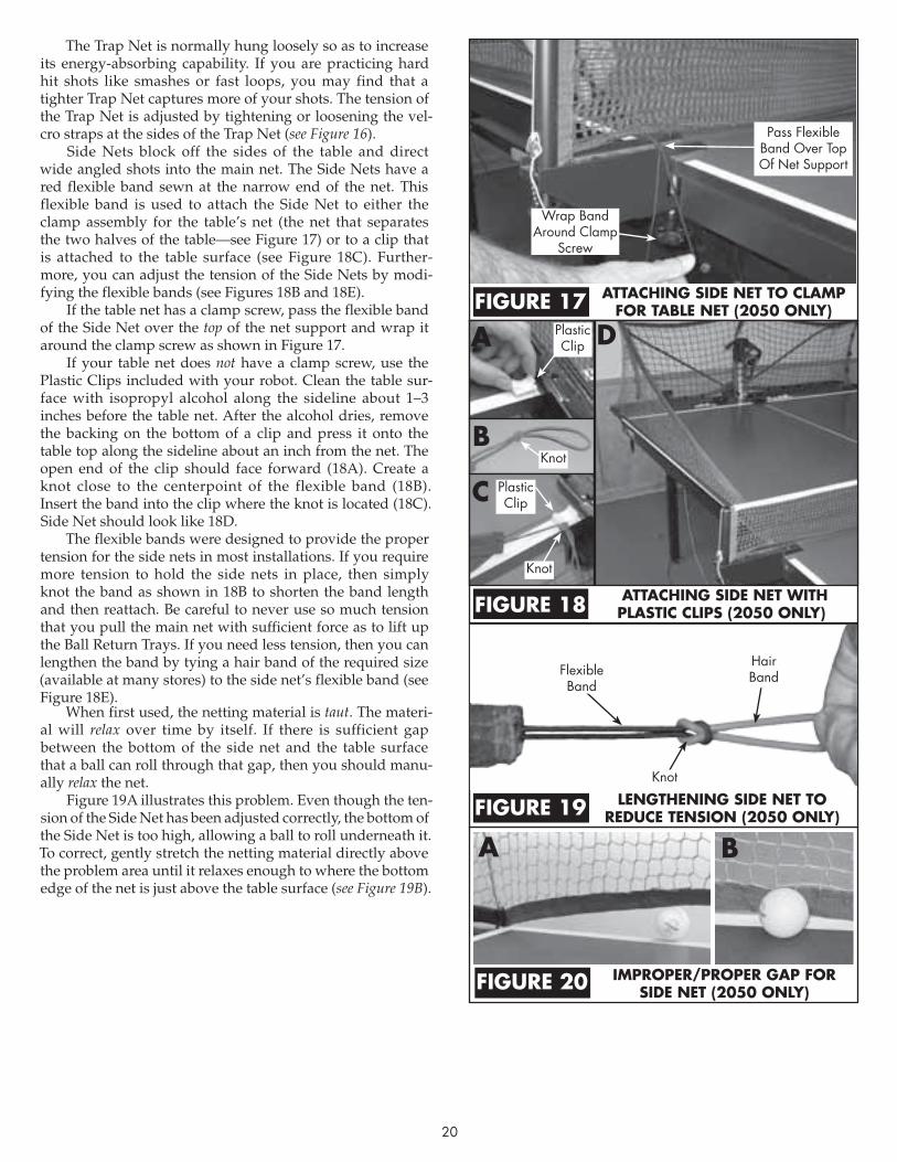
20
The Trap Net is normally hung loosely so as to increase its energy-absorbing capability. If you are practicing hard hit shots like smashes or fast loops, you may find that a tighter Trap Net captures more of your shots. The tension of the Trap Net is adjusted by tightening or loosening the vel-cro straps at the sides of the Trap Net (see Figure 16).
Side Nets block off the sides of the table and direct wide angled shots into the main net. The Side Nets have a red flexible band sewn at the narrow end of the net. This flexible band is used to attach the Side Net to either the clamp assembly for the table’s net (the net that separates the two halves of the table—see Figure 17) or to a clip that is attached to the table surface (see Figure 18C). Further-more, you can adjust the tension of the Side Nets by modi-fying the flexible bands (see Figures 18B and 18E).
If the table net has a clamp screw, pass the flexible band of the Side Net over the top of the net support and wrap it around the clamp screw as shown in Figure 17.
If your table net does not have a clamp screw, use the Plastic Clips included with your robot. Clean the table sur-face with isopropyl alcohol along the sideline about 1–3 inches before the table net. After the alcohol dries, remove the backing on the bottom of a clip and press it onto the table top along the sideline about an inch from the net. The open end of the clip should face forward (18A). Create a knot close to the centerpoint of the flexible band (18B). Insert the band into the clip where the knot is located (18C). Side Net should look like 18D.
The flexible bands were designed to provide the proper tension for the side nets in most installations. If you require more tension to hold the side nets in place, then simply knot the band as shown in 18B to shorten the band length and then reattach. Be careful to never use so much tension that you pull the main net with sufficient force as to lift up the Ball Return Trays. If you need less tension, then you can lengthen the band by tying a hair band of the required size (available at many stores) to the side net’s flexible band (see Figure 18E).
When first used, the netting material is taut. The materi-al will relax over time by itself. If there is sufficient gap between the bottom of the side net and the table surface that a ball can roll through that gap, then you should manu-ally relax the net.
Figure 19A illustrates this problem. Even though the ten-sion of the Side Net has been adjusted correctly, the bottom of the Side Net is too high, allowing a ball to roll underneath it. To correct, gently stretch the netting material directly above the problem area until it relaxes enough to where the bottom edge of the net is just above the table surface (see Figure 19B).
imprOper/prOper gap fOrside net (2050 Only)figure 20
a B
attaching side net tO clamp fOr taBle net (2050 Only)figure 17
attaching side net with plastic clips (2050 Only)figure 18
a
B
c
dPlasticClip
PlasticClip
Knot
Knot
lengthening side net tO reduce tensiOn (2050 Only)figure 19
Hair BandFlexible
Band
Knot
Pass Flexible Band Over Top Of Net Support
Wrap Band Around Clamp
Screw
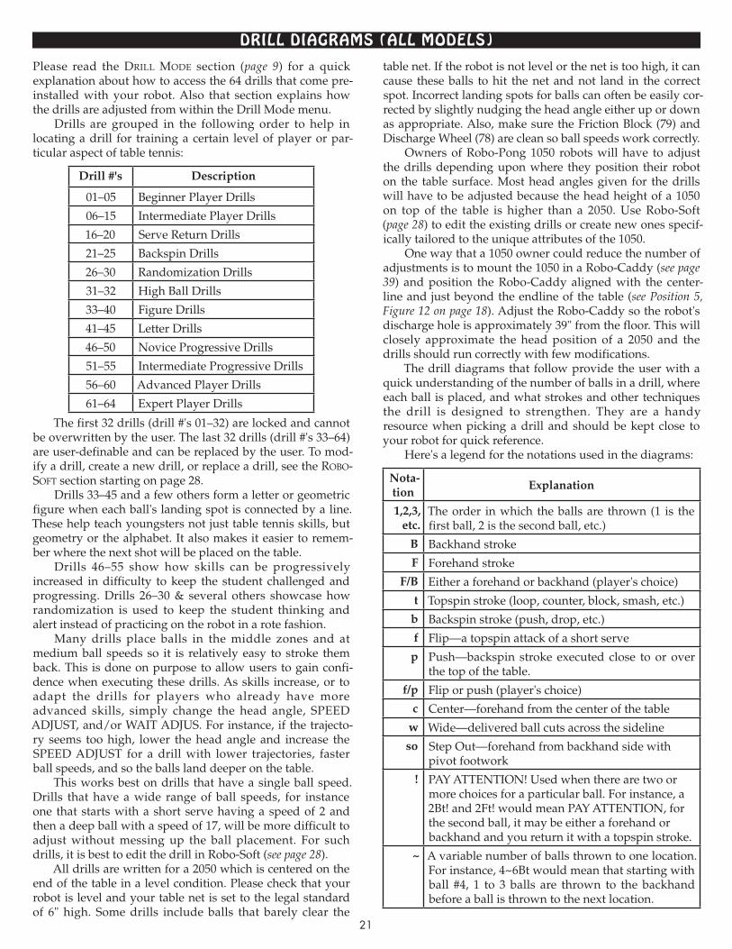
21
DRILL DIAgRAms (ALL moDeLs)Please read the Drill MODe section (page 9) for a quick explanation about how to access the 64 drills that come pre-installed with your robot. Also that section explains how the drills are adjusted from within the Drill Mode menu.
Drills are grouped in the following order to help in locating a drill for training a certain level of player or par-ticular aspect of table tennis:
Drill #'s Description
01–05 Beginner Player Drills
06–15 Intermediate Player Drills
16–20 Serve Return Drills
21–25 Backspin Drills
26–30 Randomization Drills
31–32 High Ball Drills
33–40 Figure Drills
41–45 Letter Drills
46–50 Novice Progressive Drills
51–55 Intermediate Progressive Drills
56–60 Advanced Player Drills
61–64 Expert Player Drills
The first 32 drills (drill #'s 01–32) are locked and cannot be overwritten by the user. The last 32 drills (drill #'s 33–64) are user-definable and can be replaced by the user. To mod-ify a drill, create a new drill, or replace a drill, see the rOBO-sOft section starting on page 28.
Drills 33–45 and a few others form a letter or geometric figure when each ball's landing spot is connected by a line. These help teach youngsters not just table tennis skills, but geometry or the alphabet. It also makes it easier to remem-ber where the next shot will be placed on the table.
Drills 46–55 show how skills can be progressively in creased in difficulty to keep the student challenged and progressing. Drills 26–30 & several others showcase how randomization is used to keep the student thinking and alert instead of practicing on the robot in a rote fashion.
Many drills place balls in the middle zones and at medium ball speeds so it is relatively easy to stroke them back. This is done on purpose to allow users to gain confi-dence when executing these drills. As skills increase, or to adapt the drills for players who already have more ad vanced skills, simply change the head angle, SPEED ADJUST, and/or WAIT ADJUS. For instance, if the trajecto-ry seems too high, lower the head angle and increase the SPEED ADJUST for a drill with lower trajectories, faster ball speeds, and so the balls land deeper on the table.
This works best on drills that have a single ball speed. Drills that have a wide range of ball speeds, for instance one that starts with a short serve having a speed of 2 and then a deep ball with a speed of 17, will be more difficult to adjust without messing up the ball placement. For such drills, it is best to edit the drill in Robo-Soft (see page 28).
All drills are written for a 2050 which is centered on the end of the table in a level condition. Please check that your robot is level and your table net is set to the legal standard of 6" high. Some drills include balls that barely clear the
table net. If the robot is not level or the net is too high, it can cause these balls to hit the net and not land in the correct spot. Incorrect landing spots for balls can often be easily cor-rected by slightly nudging the head angle either up or down as appropriate. Also, make sure the Friction Block (79) and Discharge Wheel (78) are clean so ball speeds work correctly.
Owners of Robo-Pong 1050 robots will have to adjust the drills depending upon where they position their robot on the table surface. Most head angles given for the drills will have to be adjusted because the head height of a 1050 on top of the table is higher than a 2050. Use Robo-Soft (page 28) to edit the existing drills or create new ones specif-ically tailored to the unique attributes of the 1050.
One way that a 1050 owner could reduce the number of adjustments is to mount the 1050 in a Robo-Caddy (see page 39) and position the Robo-Caddy aligned with the center-line and just beyond the endline of the table (see Position 5, Figure 12 on page 18). Adjust the Robo-Caddy so the robot's discharge hole is approximately 39" from the floor. This will closely approximate the head position of a 2050 and the drills should run correctly with few modifications.
The drill diagrams that follow provide the user with a quick understanding of the number of balls in a drill, where each ball is placed, and what strokes and other techniques the drill is designed to strengthen. They are a handy re source when picking a drill and should be kept close to your robot for quick reference.
Here's a legend for the notations used in the diagrams:
Nota-tion
Explanation
1,2,3, etc.
The order in which the balls are thrown (1 is the first ball, 2 is the second ball, etc.)
B Backhand stroke
F Forehand stroke
F/B Either a forehand or backhand (player's choice)
t Topspin stroke (loop, counter, block, smash, etc.)
b Backspin stroke (push, drop, etc.)
f Flip—a topspin attack of a short serve
p Push—backspin stroke executed close to or over the top of the table.
f/p Flip or push (player's choice)
c Center—forehand from the center of the table
w Wide—delivered ball cuts across the sideline
so Step Out—forehand from backhand side with pivot footwork
! PAY ATTENTION! Used when there are two or more choices for a particular ball. For instance, a 2Bt! and 2Ft! would mean PAY ATTENTION, for the second ball, it may be either a forehand or backhand and you return it with a topspin stroke.
~ A variable number of balls thrown to one location. For instance, 4~6Bt would mean that starting with ball #4, 1 to 3 balls are thrown to the backhand before a ball is thrown to the next location.

22
1Bt
09 B-F-Fc-F
TOPSPIN ANGLE: 8
3Ft2Ft4Ft
3F/Bt
07 F-Fc-B or Fso-Fc
TOPSPIN ANGLE: 8
2Ft4Ft
1Ft
08 F Short-Mid-Long
TOPSPIN ANGLE: 8
2Ft
1Ft
3Ft
06 2B-2F
TOPSPIN ANGLE: 8
1Bt2Bt
3Ft4Ft
11 Forward Slash TS
TOPSPIN ANGLE: 8
1Ff
2Bt
12 V’s
TOPSPIN ANGLE: 8
3Bt 1Ff
2Ft4Ft
02 F-Fc Beginner
TOPSPIN ANGLE: 2
2Ft 1Ft 1Bt
TOPSPIN ANGLE: 2
2Ft 3Ft
03 B-Fc-F Beginner 04 Hourglass Begin-ner
TOPSPIN ANGLE: 2
1Bt 3Ft
4Bt 2Ft
01 B-F Beginner
TOPSPIN ANGLE: 2
1Bt 2Ft
1Bt2Ft
05 Falkenberg Beginner
TOPSPIN ANGLE: 2
3Ft
1Bt3Bt
10 B-Fc-B-F
TOPSPIN ANGLE: 8
2Ft 4Ft
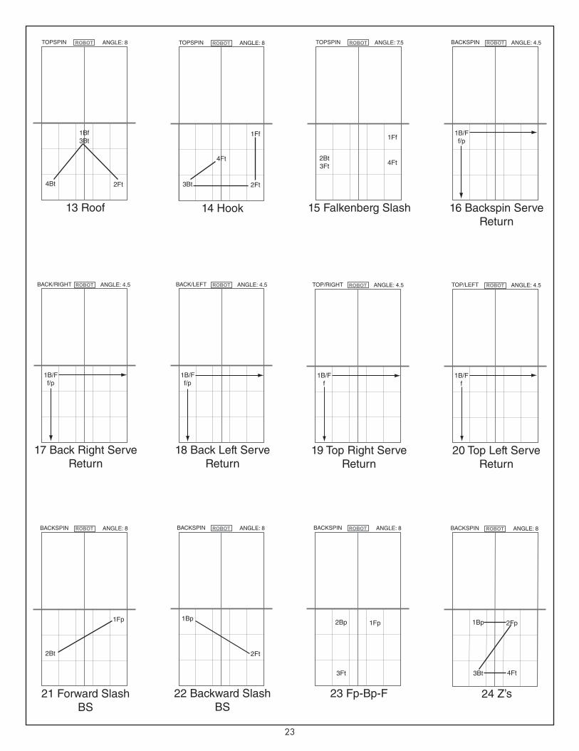
23
20 Top Left Serve Return
TOP/LEFT ANGLE: 4.5
1B/Ff
19 Top Right Serve Return
TOP/RIGHT ANGLE: 4.5
1B/Ff
22 Backward Slash BS
BACKSPIN ANGLE: 8
1Bp
16 Backspin Serve Return
BACKSPIN ANGLE: 4.5
1B/Ff/p
17 Back Right Serve Return
BACK/RIGHT ANGLE: 4.5
1B/Ff/p
18 Back Left Serve Return
BACK/LEFT ANGLE: 4.5
1B/Ff/p
24 Z’s
BACKSPIN ANGLE: 8
1Bp 2Fp
3Bt 4Ft
23 Fp-Bp-F
BACKSPIN ANGLE: 8
2Bp 1Fp
3Ft
21 Forward Slash BS
BACKSPIN ANGLE: 8
1Fp
2Ft2Bt
14 Hook
TOPSPIN ANGLE: 8
4Ft
1Ff
3Bt 2Ft
15 Falkenberg Slash
TOPSPIN ANGLE: 7.5
1Ff
2Bt3Ft 4Ft
13 Roof
TOPSPIN ANGLE: 8
1Bf3Bt
4Bt 2Ft
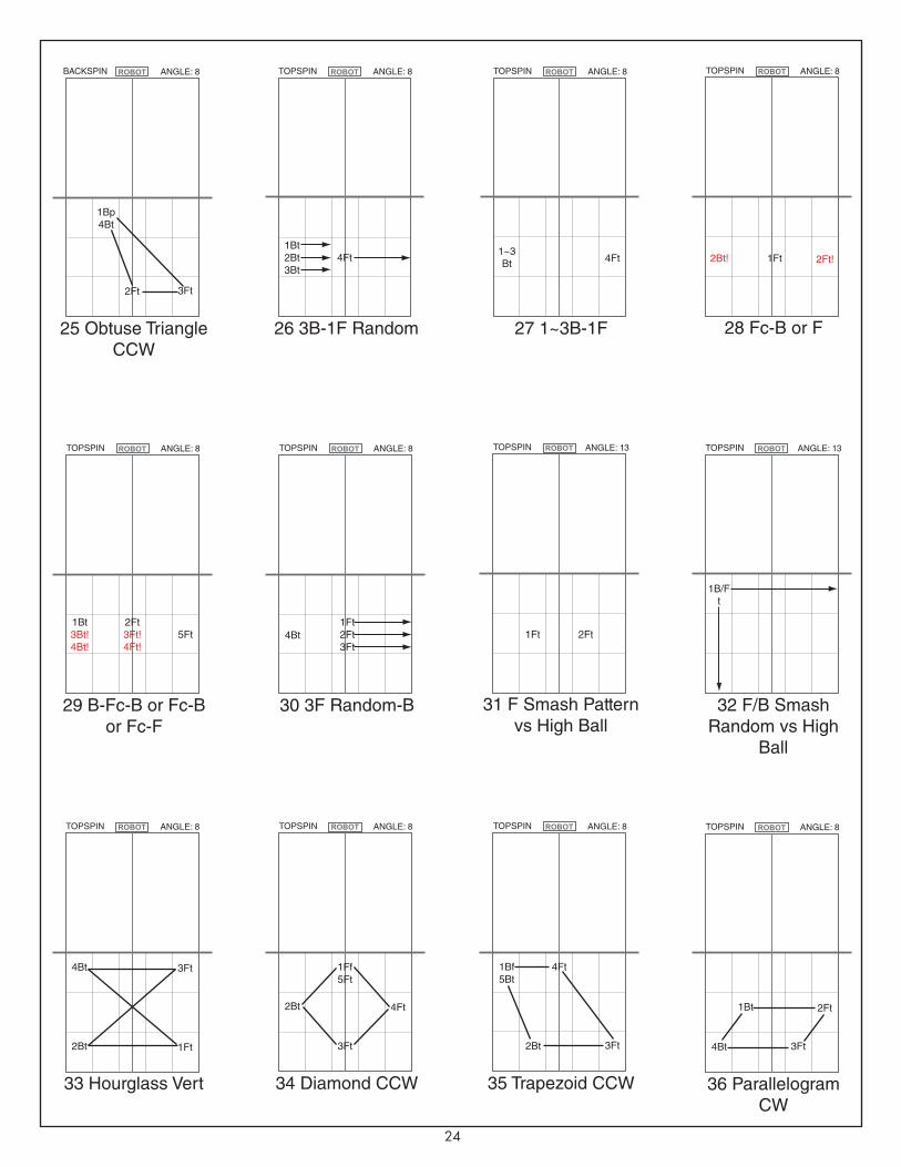
24
31 F Smash Pattern vs High Ball
TOPSPIN ANGLE: 13
1Ft 2Ft1Bt3Bt!4Bt!
29 B-Fc-B or Fc-B or Fc-F
TOPSPIN ANGLE: 8
2Ft3Ft!4Ft!
5Ft 4Bt
30 3F Random-B
TOPSPIN ANGLE: 8
1Ft2Ft3Ft
36 Parallelogram CW
TOPSPIN ANGLE: 8
1Bt 2Ft
4Bt 3Ft
25 Obtuse Triangle CCW
BACKSPIN ANGLE: 8
1Bp4Bt
2Ft 3Ft
2Bt!
28 Fc-B or F
TOPSPIN ANGLE: 8
1Ft 2Ft!1~3Bt
27 1~3B-1F
TOPSPIN ANGLE: 8
4Ft1Bt2Bt3Bt
26 3B-1F Random
TOPSPIN ANGLE: 8
4Ft
33 Hourglass Vert
TOPSPIN ANGLE: 8
4Bt 3Ft
2Bt 1Ft
32 F/B Smash Random vs High
Ball
TOPSPIN ANGLE: 13
1B/Ft
2Bt
34 Diamond CCW
TOPSPIN ANGLE: 8
4Ft
1Ff5Ft
3Ft
35 Trapezoid CCW
TOPSPIN ANGLE: 8
1Bf5Bt
4Ft
2Bt 3Ft

25
37 Rectangle CW
TOPSPIN ANGLE: 8
4Bt 1Ff5Ft
3Bt 2Ft
5Bt
38 Pentagon CW
TOPSPIN ANGLE: 8
2Ft
1Ff6Ft
4Bt 3Ft
39 Anti Parallelo-gram
TOPSPIN ANGLE: 8
1Bf5Bt
3Ft
4Bt 2Ft
43 W’s
TOPSPIN ANGLE: 8
3Ft
1Bf 5Ft
2Bt 4Ft
3Bt
40 Star
TOPSPIN ANGLE: 8
4Ft
1Bf6Ft
5Bt 2Ft
42 M’s
TOPSPIN ANGLE: 8
3Ft
2Bt 4Ft
1Bt 5Ft
41 L’s
TOPSPIN ANGLE: 8
1Bf
2Bt 3Ft
4Bt
44 F’s
TOPSPIN ANGLE: 8
5Ft
2Bt 1Ff
3Bt
45 H’s
TOPSPIN ANGLE: 8
4Bt 3Ft
6Bt 1Ff
5Bt 2Ft
47 F-Fc
TOPSPIN ANGLE: 8
2Ft 1Ft 3Bt
48 2F-B-Fc
TOPSPIN ANGLE: 8
4Ft1Ft2Ft1Bt
46 B-F
TOPSPIN ANGLE: 8
2Ft
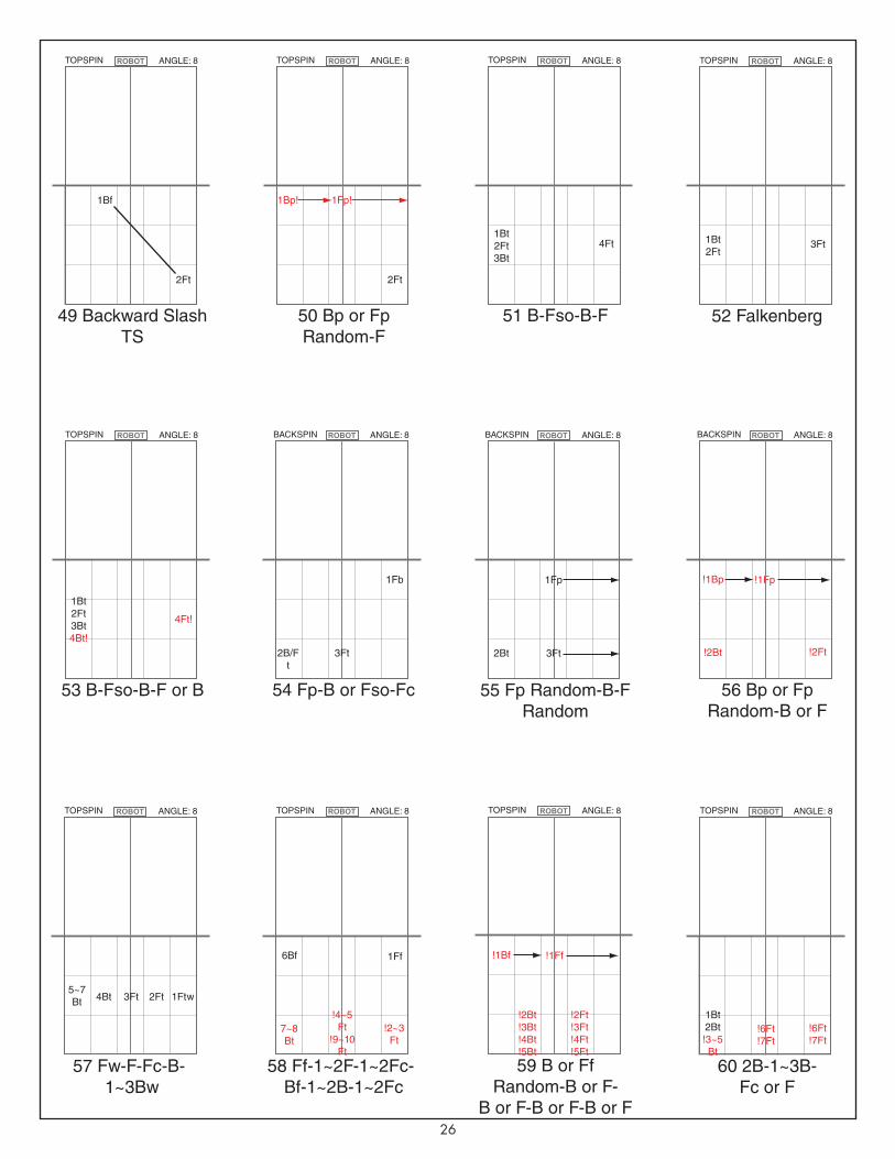
26
50 Bp or Fp Random-F
TOPSPIN ANGLE: 8
1Bp! 1Fp!
2Ft
54 Fp-B or Fso-Fc
BACKSPIN ANGLE: 8
1Fb
2B/Ft
3Ft
49 Backward Slash TS
TOPSPIN ANGLE: 8
1Bf
2Ft
!1Bp !1Fp
55 Fp Random-B-F Random
BACKSPIN ANGLE: 8
1Fp
2Bt 3Ft
52 Falkenberg
1Bt2Ft
TOPSPIN ANGLE: 8
3Ft
56 Bp or Fp Random-B or F
!2Bt
BACKSPIN ANGLE: 8
!2Ft
1Bt2Ft3Bt4Bt!
53 B-Fso-B-F or B
TOPSPIN ANGLE: 8
4Ft!
1Bt2Ft3Bt
51 B-Fso-B-F
TOPSPIN ANGLE: 8
4Ft
6Bf 1Ff
58 Ff-1~2F-1~2Fc-Bf-1~2B-1~2Fc
7~8Bt
TOPSPIN ANGLE: 8
!2~3Ft
!4~5Ft
!9~10Ft
57 Fw-F-Fc-B-1~3Bw
5~7Bt
TOPSPIN ANGLE: 8
1Ftw2Ft3Ft4Bt
59 B or Ff Random-B or F-
B or F-B or F-B or F
TOPSPIN ANGLE: 8
60 2B-1~3B-Fc or F
1Bt2Bt!3~5Bt
TOPSPIN ANGLE: 8
!6Ft!7Ft
!6Ft!7Ft
!1Bf !1Ff
!2Bt!3Bt!4Bt!5Bt
!2Ft!3Ft!4Ft!5Ft
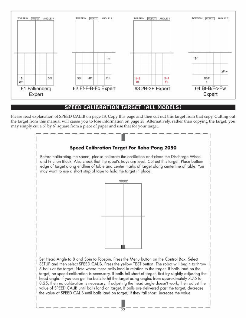
sPeeD cALIbRATIoN TARgeT (ALL moDeLs)
27
62 Ff-F-B-Fc Expert
TOPSPIN ANGLE: 7
1Ff
3Bt 4Ft 2Ft
61 Falkenberg Expert
TOPSPIN ANGLE: 7
1Bt2Ft
3Ft
63 2B-2F Expert
TOPSPIN ANGLE: 7
!1~2Bt
!3~4Ft
64 Bf-B/Fc-Fw Expert
TOPSPIN ANGLE: 7
3Ftw
1Bf
2B/Ft
Speed Calibration Target For Robo-Pong 2050
Before calibrating the speed, please calibrate the oscillation and clean the Discharge Wheel and Friction Block. Also check that the robot’s trays are level. Cut out this target. Place bottom edge of target along endline of table and center marks of target along centerline of table. You may want to use a short strip of tape to hold the target in place:
Set Head Angle to 8 and Spin to Topspin. Press the Menu button on the Control Box. Select SETUP and then select SPEED CALIB. Press the yellow TEST button. The robot will begin to throw 5 balls at the target. Note where these balls land in relation to the target. If balls land on the target, no speed calibration is necessary. If balls fall short of target, first try slightly adjusting the head angle. If you can get the balls to hit the target using angles from approximately 7.75 to 8.25, then no calibration is necessary. If adjusting the head angle doesn’t work, then adjust the value of SPEED CALIB until balls land on target. If balls are delivered past the target, decrease the value of SPEED CALIB until balls land on target; if they fall short, increase the value.
Please read explanation of SPEED CALIB on page 13. Copy this page and then cut out this target from that copy. Cutting out the target from this manual will cause you to lose information on page 28. Alternatively, rather than copying the target, you may simply cut a 6″ by 6″ square from a piece of paper and use that for your target.
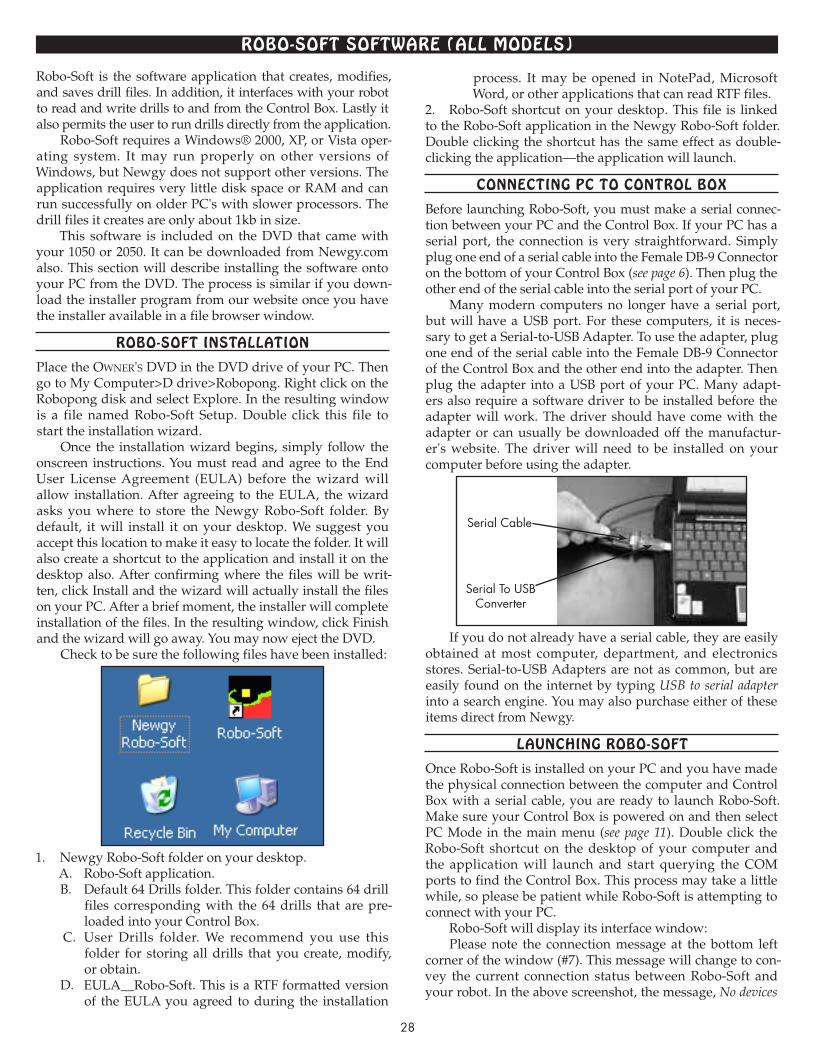
28
Robo-sofT sofTwARe (ALL moDeLs)
Robo-Soft is the software application that creates, modifies, and saves drill files. In addition, it interfaces with your robot to read and write drills to and from the Control Box. Lastly it also permits the user to run drills directly from the application.
Robo-Soft requires a Windows® 2000, XP, or Vista oper-ating system. It may run properly on other versions of Windows, but Newgy does not support other versions. The application requires very little disk space or RAM and can run successfully on older PC's with slower processors. The drill files it creates are only about 1kb in size.
This software is included on the DVD that came with your 1050 or 2050. It can be downloaded from Newgy.com also. This section will describe installing the software onto your PC from the DVD. The process is similar if you down-load the installer program from our website once you have the installer available in a file browser window.
Robo-sofT INsTALLATIoN
Place the Owner's DVD in the DVD drive of your PC. Then go to My Computer>D drive>Robopong. Right click on the Robopong disk and select Explore. In the resulting window is a file named Robo-Soft Setup. Double click this file to start the installation wizard.
Once the installation wizard begins, simply follow the onscreen instructions. You must read and agree to the End User License Agreement (EULA) before the wizard will allow installation. After agreeing to the EULA, the wizard asks you where to store the Newgy Robo-Soft folder. By default, it will install it on your desktop. We suggest you accept this location to make it easy to locate the folder. It will also create a shortcut to the application and install it on the desktop also. After confirming where the files will be writ-ten, click Install and the wizard will actually install the files on your PC. After a brief moment, the installer will complete installation of the files. In the resulting window, click Finish and the wizard will go away. You may now eject the DVD.
Check to be sure the following files have been installed:
1. Newgy Robo-Soft folder on your desktop.A. Robo-Soft application.B. Default 64 Drills folder. This folder contains 64 drill
files corresponding with the 64 drills that are pre-loaded into your Control Box.
C. User Drills folder. We recommend you use this folder for storing all drills that you create, modify, or obtain.
D. EULA__Robo-Soft. This is a RTF formatted version of the EULA you agreed to during the installation
process. It may be opened in NotePad, Microsoft Word, or other applications that can read RTF files.
2. Robo-Soft shortcut on your desktop. This file is linked to the Robo-Soft application in the Newgy Robo-Soft folder. Double clicking the shortcut has the same effect as double-clicking the application—the application will launch.
coNNecTINg Pc To coNTRoL boX
Before launching Robo-Soft, you must make a serial connec-tion between your PC and the Control Box. If your PC has a serial port, the connection is very straightforward. Simply plug one end of a serial cable into the Female DB-9 Connector on the bottom of your Control Box (see page 6). Then plug the other end of the serial cable into the serial port of your PC.
Many modern computers no longer have a serial port, but will have a USB port. For these computers, it is neces-sary to get a Serial-to-USB Adapter. To use the adapter, plug one end of the serial cable into the Female DB-9 Connector of the Control Box and the other end into the adapter. Then plug the adapter into a USB port of your PC. Many adapt-ers also require a software driver to be installed before the adapter will work. The driver should have come with the adapter or can usually be downloaded off the manufactur-er's website. The driver will need to be installed on your computer before using the adapter.
If you do not already have a serial cable, they are easily obtained at most computer, department, and electronics stores. Serial-to-USB Adapters are not as common, but are easily found on the internet by typing USB to serial adapter into a search engine. You may also purchase either of these items direct from Newgy.
LAuNchINg Robo-sofT
Once Robo-Soft is installed on your PC and you have made the physical connection between the computer and Control Box with a serial cable, you are ready to launch Robo-Soft. Make sure your Control Box is powered on and then select PC Mode in the main menu (see page 11). Double click the Robo-Soft shortcut on the desktop of your computer and the application will launch and start querying the COM ports to find the Control Box. This process may take a little while, so please be patient while Robo-Soft is attempting to connect with your PC.
Robo-Soft will display its interface window:Please note the connection message at the bottom left
corner of the window (#7). This message will change to con-vey the current connection status between Robo-Soft and your robot. In the above screenshot, the message, No devices
Serial To USB Converter
Serial Cable

29
found means the connection attempt failed. If the connec-tion attempt was successful, this message would be, Successfully connected to device on COM xx with xx represent-ing the number of the COM port that is being used.
Besides this connection status message, the Control Box confirms a successful connection by displaying a check mark in its lower right corner (see page 11). Once you re ceive a Successfully connected message and a visible check mark on the LCD screen, you're ready to start using Robo-Soft.
Should Robo-Soft fail to establish communications with the Control Box when it first launches, you may instruct Robo-Soft to try again by selecting Device>AutoConnect. Sometimes it takes 2 or 3 attempts before a successful con-nection is established. If unsuccessful, check that your phys-ical connection is secure and that the Control Box is switched to PC Mode. If both of these check out, but you're still unable to connect, call Newgy Customer Service.
If you only wish to open and save drill files that reside on your PC or a connected drive, you do not need to have your PC connected by serial cable. Robo-Soft will function correctly if you do not need it to communicate with the Control Box. You will not be able to read drills from or write drills to the Control Box or run drills direct from Robo-Soft, but you can open, modify, and save drill files stored on one of the PC's drives.
Robo-sofT INTeRfAce
Following is an explanation of the various parts of the Robo-Soft interface:
1. VERSION # & FILE PATH—At the upper left corner is the current version number of Robo-Soft. If any informa-tion is displayed after the version number, this indicates that Robo-Soft is reading a drill from a drill file stored on your PC and is displaying the file path to that drill file.
2. MENU BAR—Standard menu bar for any PC appli-cation. Contains menus of commands. Click on a menu title to reveal a pull-down menu of commands.
Device—Menu is used to Connect or Disconnect com-munications with the Control Box. Also contains a Set Drills To Factory command which is used to restore all 64 drills that came with your robot to the Control Box.
File—Used to create a new drill file, open an existing drill file, or save a modified or new drill file.
Undo—Undoes the last action.About—Provides information about the software
including a copyright notice and version number.3. PROGRAMMED CONTROL—Used to display and
modify the commands and values in a drill file.Spin—Allows selection of the type of spin by using the
adjacent < and > buttons. Toggles through Top, Back, R Side,
12
3
4
5
6
7

30
L Side, Top/Right, Top/Left, Back/Right, and Back/Left. Please note that this does not physically change the spin on the robot, but provides the desired spin setting for a drill to the user. The user must manually rotate the robot head to the selected spin (see page 16).
Head Angle—Used to specify the head angle for a drill. Use the adjacent < and > buttons to select a value from 1 to 13. Includes half increments such as 1.5, 2.5, etc.. Like Spin, does not actually move the head angle; the user must man-ually move the head up or down (see page 15).
#—This column is automatically filled in as commands are added to a drill. As each new command is added, this field labels the line with the next whole number starting with 1. This helps the user keep track of the lines.
Command—Use the < or > buttons in this column to select a command. The commands toggle through Speed, Position, Throw, Wait, and Beep. Speed and Position corre-late to BALL SPEED and POSITION in Normal Mode (see page 7). Wait is similar to WAIT of normal mode in that it provides an interval of time between shots. However, it is calculated differently, and this difference is discussed in the next section. Beep provides an auditory tone to signal the user to do a certain action or inform him of drill progress.
Value—Allows user to input a value for the selected command. Use the < and > buttons in this column to select values allowed for each command.
Edit—This column has 4 buttons for each line, (copy), (paste), (insert) and (delete). Action triggered by
these buttons apply to the entire line so, for example, the button will copy both the Command and Value on that line.
4. RUN CONTROL—Not labeled, but this section is located at the upper right corner. Used to run and modify the drill displayed in Programmed Control direct from Robo-Soft.
# of Reps—Also not labeled, but the large number field is used for inputting the number of repetitions of a drill you want to run. Can be set to any whole number and will count down as each repetition completes. When count reaches 0, the drill will stop running and it will automatically reset to the last number that was input. If stopped before reaching 0, it will resume at the last repetition before it was stopped.
Run—Starts running the drill that currently is shown in the Programmed Control Section. Robot will give a 3 sec-ond start up beep sequence before throwing the first ball to allow time for the user to get ready to return the balls.
Stop—Stops a currently running drill when pressed. When running drills direct from Robo-Soft, the Stop/Start Button on the Control Box is deactivated. Pressing the Stop button in the Robo-Soft interface is the only way to stop a drill before the # of Reps counts down to 0.
Wait Adjust %—Increases or decreases as a percentage the wait times of a drill. Similar to WAIT ADJUS in Drill Mode (see page 10) except wait time can be adjusted in sin-gle increments instead of increments of 10.
Speed Adj—Adjusts the Speeds of a drill. Similar to SPEED ADJUST of Drill Mode (see page 10). Clicking on the adjacent small white check box changes the increments from a whole number to a percentage. For example, a +10 entered in the input field will increase all Speeds by 10, so a Speed of 2 becomes 12 and 15 becomes 25. However, check-ing the box changes this to 10%, so a Speed of 2 becomes 2.2 and 15 becomes 16.5.
5. DRILLS ON CONTROLLER—This section is for reading drills from or writing drills to the Control Box. Drill information is stored on the microprocessor in protected memory locations associated with each drill (01–64).
Drill #—Selects the drill associated with that number.Read—To read the selected drill, press this button and
the commands and values of that drill will be displayed in the Programmed Control section. All drills can be read, including drills 01–32.
Write—Writes the drill described in the Programmed Control section to the Control Box, at the memory location listed in Drill #. Doing so overwrites the drill previously stored in that location. Only drills 33–64 can be overwritten. Use this function with caution as this action cannot be undone. Also there is a size limitation for drills. If drills are too large to be written to the allocated memory location, Robo-Soft will not permit the drill to be written to the chip.
Progress Bar—Located immediately under the Read and Write buttons, this bar shows the progress of the read or write action. Watch quickly as it typically takes less than a second to complete reads and writes.
6. MANUAL CONTROL—This section is handy for test-ing settings for an individual ball throw when writing a drill. Similar to the Test Button function in Normal Mode. After finding the settings for the desired type of shot, set the com-mands and values obtained in this section to the Programmed Control section to get the same type of shot in a drill.
Throw Balls—Press button to start ball delivery.Stop —Button tells robot to stop throwing balls. Balls
will automatically stop when Balls counts down to zero.Balls—Input the number of balls you want thrown to
test your settings.Wait (sec)—The interval of time between each test ball.
This setting should not be used for testing Wait commands in a drill. The Wait in a drill can be influenced by the previ-ous ball. In Manual Control, each ball is the same so previ-ous balls do not influence successive balls. Always run drill with Run Control to test Waits for that drill.
Speed—Sets ball speed for the test balls.Direction—Same as POSITION in Normal Mode.7. CONNECTION STATUS—Gives the current connec-
tion status. One of the following messages is shown:A. No devices found! No connection has been established
between Robo-Soft and the Control Box. Check cables and make sure Control Box is switched to PC Mode.
B. Successfully Connected to Device on COM xx! Robo- Soft has successfully connected to the Control Box and pro-vides the COM port being used (xx is replaced with a num-ber). Drills may be read from or written to the Control Box, and drills can be run direct from the PC.
C. The device is not found on COM xx! Shown after a manual connection request in which a specific COM port (shown in place of xx) is tested. If test fails, this message is shown. If test succeeds, message B is displayed.
D. Disconnected! Robo-Soft is no longer connected to the Control Box.
uNDeRsTANDINg DRILL commANDs
Perhaps the simplest way to start working with drills in Robo-Soft is to read and write drills back and forth with the
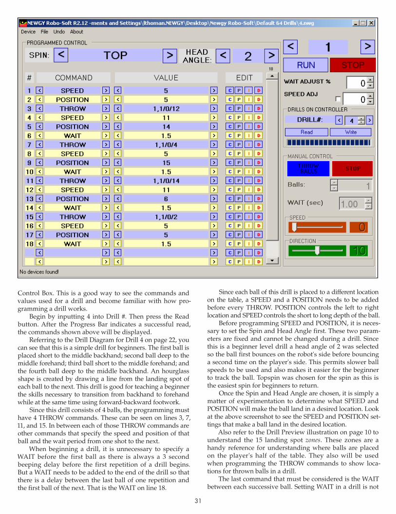
31
Control Box. This is a good way to see the commands and values used for a drill and become familiar with how pro-gramming a drill works.
Begin by inputting 4 into Drill #. Then press the Read button. After the Progress Bar indicates a successful read, the commands shown above will be displayed.
Referring to the Drill Diagram for Drill 4 on page 22, you can see that this is a simple drill for beginners. The first ball is placed short to the middle backhand; second ball deep to the middle forehand; third ball short to the middle forehand; and the fourth ball deep to the middle backhand. An hourglass shape is created by drawing a line from the landing spot of each ball to the next. This drill is good for teaching a beginner the skills necessary to transition from backhand to forehand while at the same time using forward-backward footwork.
Since this drill consists of 4 balls, the programming must have 4 THROW commands. These can be seen on lines 3, 7, 11, and 15. In between each of those THROW commands are other commands that specify the speed and position of that ball and the wait period from one shot to the next.
When beginning a drill, it is unnecessary to specify a WAIT before the first ball as there is always a 3 second beeping delay before the first repetition of a drill begins. But a WAIT needs to be added to the end of the drill so that there is a delay between the last ball of one repetition and the first ball of the next. That is the WAIT on line 18.
Since each ball of this drill is placed to a different location on the table, a SPEED and a POSITION needs to be added before every THROW. POSITION controls the left to right lo ca tion and SPEED controls the short to long depth of the ball.
Before programming SPEED and POSITION, it is neces-sary to set the Spin and Head Angle first. These two param-eters are fixed and cannot be changed during a drill. Since this is a beginner level drill a head angle of 2 was selected so the ball first bounces on the robot's side before bouncing a second time on the player's side. This permits slower ball speeds to be used and also makes it easier for the beginner to track the ball. Topspin was chosen for the spin as this is the easiest spin for beginners to return.
Once the Spin and Head Angle are chosen, it is simply a matter of experimentation to determine what SPEED and POSITION will make the ball land in a desired location. Look at the above screenshot to see the SPEED and POSITION set-tings that make a ball land in the desired location.
Also refer to the Drill Preview illustration on page 10 to understand the 15 landing spot zones. These zones are a handy reference for understanding where balls are placed on the player's half of the table. They also will be used when programming the THROW commands to show loca-tions for thrown balls in a drill.
The last command that must be considered is the WAIT between each successive ball. Setting WAIT in a drill is not

32
as straightforward as setting the WAIT in Normal Mode. It varies depending upon how long it takes for the robot to respond to the SPEED and POSITION commands before the THROW command is executed.
In Normal Mode, WAIT is pretty straightforward—it is the interval of time between each shot. So if WAIT is set to 1 second, there is almost exactly 1 second between when one ball is shot and the next ball is shot (provided there is no randomization of WAIT).
But in drills, WAIT is the period of time remaining after the other commands have been executed. Commands must be executed in sequential order and it takes a certain amount of time for the robot to execute each command.
In this example drill, it takes a certain amount of time for the robot to change from SPEED 5 for the first ball to SPEED 11 for the second ball and then change from POSITION 5 for the first ball to POSITION 14 for the second ball. Only after it completes these two commands, can it then respond to a WAIT command that comes afterward. The greater the dif-ference in SPEED and POSITION from one shot to the next, the longer it will take the robot to respond to those com-mands and the less WAIT time that needs to be added.
In almost all cases, a WAIT in a drill will be less than the WAIT in Normal Mode to achieve the same timing between shots. Even though the WAIT is set at a consistent 1.5 seconds in this drill, there is actually a longer interval than this between each shot. It's not very intuitive, but by experimenting with WAIT's in a drill, you can eventually figure out the proper timing for the drill.
Another important factor for understanding a drill is the order of the commands. In almost all cases, it is best to write the commands in the following order:
1st SPEED2nd POSITION3rd WAIT4th THROWThis order seems to produce the best and most consis-
tent results when the drill is run. Changing the above order usually results in different timing between shots.
While most of the values associated with the com-mands seem pretty straightforward, the values for the THROW commands need further explanation. Pro gram-ming can be done in either simple or complex language. In simple language, it is readily apparent what you get: a
"THROW 1" command means one ball is thrown and "WAIT 1.5" means there is a 1.5 second wait period.
The THROW values shown in this example drill are complex language. Complex language allows access to sev-eral functions that are not readily apparent to the average user. To someone who has experience in programming or using advanced database or spreadsheet commands, then these commands will make perfect sense. But since there are only a few complex commands, most users should be able to master them with a little study in their use. These complex commands are used to introduce randomness and variability to drills and/or to enable Drill Preview.
If there is a comma separating two numbers in the Value field, that means the robot will select any one of the numbers listed. So, for instance, a "SPEED 14,16,18,20" com-mand (using a comma between numbers, up to four
numbers maximum, with no spaces) means the robot will randomly select a Ball Speed of 14, 16, 18, or 20.
A "SPEED 14-20" command (using a dash between two numbers and no spaces) means the robot can select any number between the two numbers listed. So the robot could select a Ball Speed of 14, 15, 16, 17, 18, 19, or 20.
The THROW command is especially complex if it con-tains forward slashes (/). The number before the first slash is the number of balls to throw. This must contain at least two numbers separated by either a comma or dash, the same as the above two examples. So for instance, if the com-mand "THROW 1,2/1.0/5" was used, the "1,2" portion would mean throw either 1 or 2 balls in a row to the same landing spot. The number between slashes, "1.0", is used to specify the WAIT time between shots if more than 1 ball is thrown. So in this case, it means if 2 balls are thrown, there is a WAIT of 1 second between the two shots.
The last parameter, the one after the second slash, corre-sponds with the zone in Drill Preview to indicate the land-ing spot of the ball. So, using the above example, the "5" after the second slash would cause a dot to be shown in Zone 5 when that ball throw is shown in Preview.
If you want to use the Preview function, but do not need the other parameters, you still must use this same complex language. As shown in the example drill on the previous page, "THROW 1,1/0/4" on line 7 means throw 1 ball with no wait between shots (because there is only 1 ball to be thrown) and with a Preview zone of 4.
Lastly, it is desirable to condense several commands into one and shorten drill length as much as possible. If you do not change SPEED or POSITION between successive shots, it is not necessary to repeat those commands before every THROW. This can be seen on several of the 64 drills that contain a single SPEED command at the beginning that does not change for the entire drill.
If you examine the programming for Drill #52, you will see another example of this drill command condensation. This is the classic Falkenberg drill where two balls are thrown to the backhand side and one to the forehand. Line 3 shows the command, "THROW 2,2/0.7/6". This one com-mand results in 2 balls being thrown to the backhand instead of two separate THROW and WAIT commands for the two balls going to one position.
wRITINg, moDIfyINg & sAvINg DRILLs
Let's move on to a practical exercise to modify a drill, test it, and then store it as a new drill on the Control Box. Using Drill 4 as a working example, let's assume that after using this drill for several weeks, a beginner's skill level has increased to a point where the drill needs to be made more challenging. A simple way to do this would be to widen out the lateral range so the beginner will have to move his/her feet more. Let's make that change to that drill.
With Drill 4 displayed in Programmed Control, go to the first POSITION and change the Value from 5 to 0, the second one from 14 to 17, the third from 15 to 20, and the fourth from 5 to 3. This should effectively move the two backhand shots over one zone to the left and the two fore-hand shots over one zone to the right. This will force the player to cover the entire table instead of just the middle.
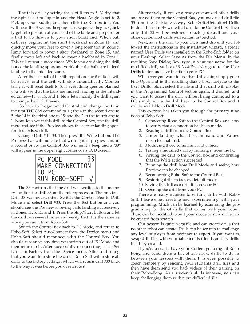
33
Test this drill by setting the # of Reps to 5. Verify that the Spin is set to Topspin and the Head Angle is set to 2. Pick up your paddle, and then click the Run button. You will hear the 3 second beeping start sequence begin. Quick-ly get into position at your end of the table and prepare for a ball to be thrown to your short backhand. When ball delivery begins, hit the short backhand in Zone 11, and quickly move your feet to cover a long forehand in Zone 5. Jump forward to cover a short forehand to Zone 15, and finally move left and back to cover a backhand in Zone 1. This will repeat 4 more times. While you are doing the drill, notice the landing spots and verify that the balls are indeed landing in the intended zones.
After the last ball of the 5th repetition, the # of Reps will be at zero and the drill will stop automatically. Momen-tarily it will reset itself to 5. If everything goes as planned, you will see that the balls are indeed landing in the intend-ed zones—11, 5, 15, and 1. Now let's modify the drill again to change the Drill Preview.
Go back to Programmed Control and change the 12 in the first THROW command to 11; the 4 in the second one to 5; the 14 in the third one to 15; and the 2 in the fourth one to 1. Now, let's write this drill to the Control Box, test the drill there and see if the Preview shows the correct landing spots for this revised drill.
Change Drill # to 33. Then press the Write button. The Progress Bar will indicate that writing is in progress and in a second or so, the Control Box will emit a beep and a "33" will appear in the upper right corner of its LCD Screen:
PC MODEMAKE CONNECTIONTO PCRUN ROBO-SOFT
33
The 33 confirms that the drill was written to the memo-ry location for drill 33 on the microprocessor. The previous Drill 33 was overwritten. Switch the Control Box to Drill Mode and select Drill #33. Press the Test Button and you should see the Preview showing balls landing successively in Zones 11, 5, 15, and 1. Press the Stop/Start button and let the drill run several times and verify that it is the same as when you ran it from Robo-Soft.
Switch the Control Box back to PC Mode, and return to Robo-Soft. Select AutoConnect from the Device menu and Robo-Soft should reconnect with the Control Box. You should reconnect any time you switch out of PC Mode and then return to it. After successfully reconnecting, select Set Drills To Factory from the Device menu. After confirming that you want to restore the drills, Robo-Soft will restore all drills to the factory settings, which will return drill #33 back to the way it was before you overwrote it.
Alternatively, if you've already customized other drills and saved them to the Control Box, you may read drill file 33 from the Desktop>Newgy Robo-Soft>Default 64 Drills folder. Then simply write that drill to the Control Box. Then only drill 33 will be restored to factory default and your other customized drills will remain untouched.
Next, save the drill to your PC's hard drive. If you fol-lowed the instructions in the installation wizard, a folder named User Drills was installed in the Robo-Soft folder on your Desktop. Select Save As from the File Menu. In the resulting Save Dialog Box, type in a unique name for the modified drill, such as 33 Modified. Navigate to the User Drills folder and save the file to your PC.
Whenever you want to use that drill again, simply go to File>Open and in the resulting dialog box, navigate to the User Drills folder, select the file and that drill will display in the Programmed Control section again. If desired, and you want to access the drill without being connected to a PC, simply write the drill back to the Control Box and it will be available in Drill Mode.
This exercise has taken you through the primary func-tions of Robo-Soft:
1. Connecting Robo-Soft to the Control Box and how to verify that a connection has been made.
2. Reading a drill from the Control Box.3. Understanding what the Command and Values
mean for that drill.4. Modifying those commands and values.5. Testing a modified drill by running it from the PC.6. Writing the drill to the Control Box and confirming
that the Write action succeeded.7. Running the drill from Drill Mode and seeing how
Preview can be changed.8. Reconnecting Robo-Soft to the Control Box.9. Restoring drills to factory default mode.10. Saving the drill as a drill file on your PC.11. Opening the drill from your PC.There are many nuances to writing drills with Robo-
Soft. Please enjoy creating and experimenting with your programming. Much can be learned by examining the pro-gramming for the 64 drills that comes with your robot. These can be modified to suit your needs or new drills can be created from scratch.
Our system is quite versatile and can create drills that no other robot can create. Drills can be written to challenge any level of player from beginner to expert. If you want to, swap drill files with your table tennis friends and try drills that they created.
If you're a coach, have your student get a digital Robo-Pong and send them a list of homework drills to do in between your lessons with them. It is even possible to coach remotely by sending your students drill files and then have them send you back videos of their training on their Robo-Pong. As a student's skills increase, you can keep challenging them with more difficult drills.
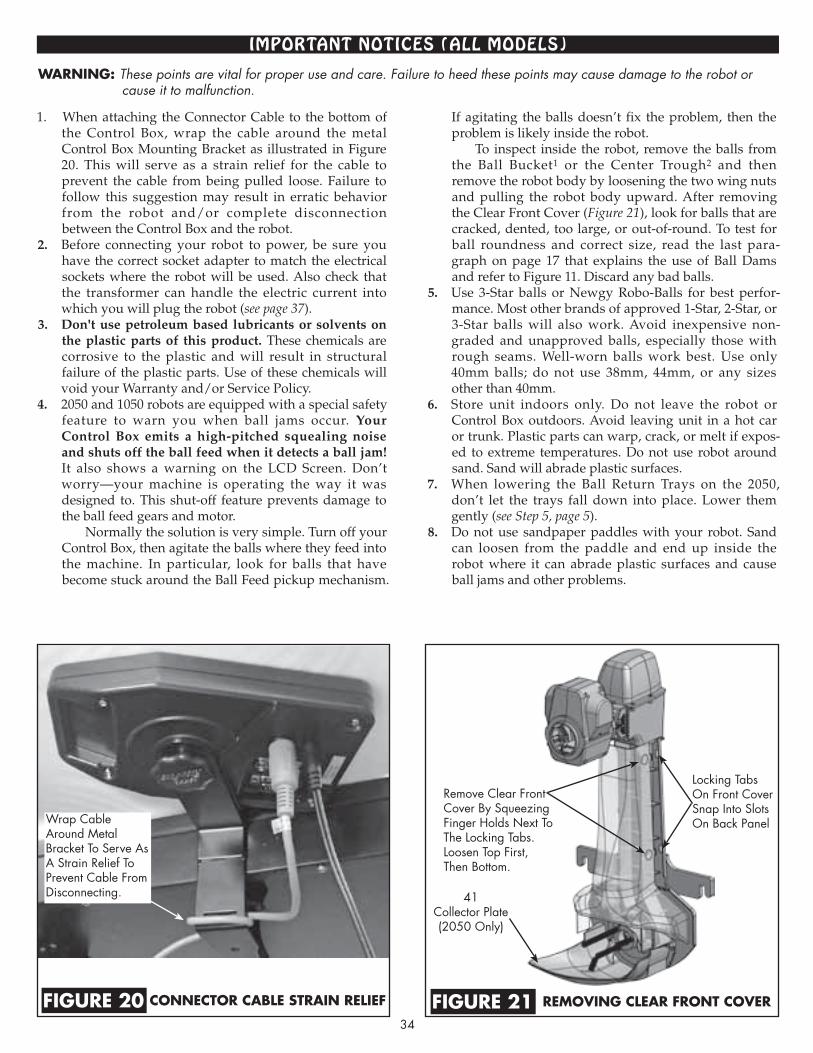
34
1. When attaching the Connector Cable to the bottom of the Con trol Box, wrap the cable around the metal Control Box Mounting Bracket as illustrated in Figure 20. This will serve as a strain relief for the cable to prevent the cable from being pulled loose. Fail ure to follow this suggestion may result in erratic behavior from the robot and/or complete disconnection be tween the Control Box and the robot.
2. Before connecting your robot to power, be sure you have the correct socket adapter to match the electrical sockets where the robot will be used. Also check that the transformer can handle the electric current into which you will plug the robot (see page 37).
3. Don't use petroleum based lubricants or solvents on the plastic parts of this product. These chemicals are corrosive to the plastic and will result in structural failure of the plastic parts. Use of these chemicals will void your Warranty and/or Service Policy.
4. 2050 and 1050 robots are equipped with a special safety feature to warn you when ball jams occur. Your Control Box emits a high-pitched squealing noise and shuts off the ball feed when it detects a ball jam! It also shows a warning on the LCD Screen. Don’t worry—your machine is operating the way it was designed to. This shut-off feature prevents damage to the ball feed gears and motor.
Normally the solution is very simple. Turn off your Control Box, then agitate the balls where they feed into the machine. In particular, look for balls that have become stuck around the Ball Feed pickup mechanism.
If agitating the balls doesn’t fix the problem, then the problem is likely inside the robot.
To inspect inside the robot, remove the balls from the Ball Bucket1 or the Center Trough2 and then re move the robot body by loosening the two wing nuts and pulling the robot body upward. After removing the Clear Front Cover (Figure 21), look for balls that are cracked, dented, too large, or out-of-round. To test for ball roundness and correct size, read the last para-graph on page 17 that explains the use of Ball Dams and refer to Figure 11. Discard any bad balls.
5. Use 3-Star balls or Newgy Robo-Balls for best per for-mance. Most other brands of approved 1-Star, 2-Star, or 3-Star balls will also work. Avoid inexpensive non-graded and unapproved balls, especially those with rough seams. Well-worn balls work best. Use only 40mm balls; do not use 38mm, 44mm, or any sizes other than 40mm.
6. Store unit indoors only. Do not leave the robot or Control Box outdoors. Avoid leaving unit in a hot car or trunk. Plastic parts can warp, crack, or melt if expos-ed to extreme temperatures. Do not use robot around sand. Sand will abrade plastic surfaces.
7. When lowering the Ball Return Trays on the 2050, don’t let the trays fall down into place. Lower them gently (see Step 5, page 5).
8. Do not use sandpaper paddles with your robot. Sand can loosen from the paddle and end up inside the robot where it can abrade plastic surfaces and cause ball jams and other problems.
ImPoRTANT NoTIces (ALL moDeLs)
warning: These points are vital for proper use and care. Failure to heed these points may cause damage to the robot or cause it to malfunction.
remOving clear frOnt cOvercOnnectOr caBle strain relief figure 21figure 20
41Collector Plate(2050 Only)
Locking Tabs On Front Cover Snap Into Slots On Back PanelWrap Cable
Around Metal Bracket To Serve As A Strain Relief To Prevent Cable From Disconnecting.
Remove Clear Front Cover By Squeezing Finger Holds Next To The Locking Tabs. Loosen Top First, Then Bottom.

35
place cOrds in center trOughUnplug all cables from the Control Box and unplug the Transformer from
the wall outlet. Coil all cords and place them on top of the balls in the Center Trough. Place the Side Nets rolled a ro u n d t h e S i d e N e t Extenders just inside the Ball Dams. If you have Pong-Master, you may place its scoreboard and all of its cords on top of the balls as well.
place side nets in traysFirst, unplug the Connector Cable from the back of the robot. Then detach the Side Nets, roll each around its Side Net Extender a few times, and place them in the trays.
insert Ball damsPush the balls into the Center Trough and place the Ball D a m s i n t h e i r
re taining slots. (See Figures 8 & 9 on page 17 for more detail.)
prepare cB Bracket fOr stOragePlace the Control Box face down on the table. Unscrew it from the mount-
ing arm, flip the bracket around, and then reattach it through its storage hole (the hole closest to the rectangular slot) as shown.
place rOBOt On cOrner Of taBleRemove the robot from the table and set it down
on the corner of the table so you can easily access both the front and back of the robot.
remOve Ball damsFrom the front of the robot, raise each tray slightly and
re move the Ball Dams from their storage po si tions. Don’t raise too much or the balls will fall out! (See Fi gures 8 & 10 on page 17 for more detail.)
TAke DowN, sToRAge, & TRANsPoRT (2050 oNLy)
1
2
3
4
5
6
Robo-Pong 2050 can be easily taken down in less than 5 minutes. Your robot folds very compactly with all parts inside the robot. This model is also lightweight and very portable. Follow these steps to be sure all parts fold up correctly.
Insert Ball Dam Into
Retainer Slot
Removing Ball Dam
From Storage
Slot
put cOntrOl BOx On stOrage pOstHold the Control Box with the buttons facing y o u a n d t h e
brac ket facing away. Raise the support leg as sem bly and slide the Control Box onto its stor-age post between the Sup port Legs. Keep as sem bly raised to pre-vent Control Box from falling off the post.
fOld Back suppOrt assemBlySet the robot head to Topspin and raise it to its highest angle. Then swing
the Support Legs inward and fold the whole support leg as sembly, with the Control Box attached, into the robot as shown. You may need to hold up the Trap Net while folding the assembly so it does not interfere with the folding process.
7
8
Storage Post For
Attaching Control
Box
Control Box In Storage Position
➨
➨
➨

36
fOld trays upFold the Ball Return Trays closed by lift-ing carefully until they lock into their verti cal position.
place net tuBes in stOrage hOlesFrom the back of the robot , de tach the left and right Cur-
ved Net Sup port Tubes from their asso ciated Straight Net Sup port Tubes. Place the cur-ved tubes into their stor age holes (2nd & 4th holes) on top of the Net Support Plate.
rOBOt prOperly fOldedWhen the robot is fully folded and with its components in their proper storage posi tions, all parts fit within the confines of the Center Trough and the Ball Return Trays.
9
10
11
Separating The Upper And Lower
Net Support Tubes
Net Support Plate
place rOBOt in rOBO-tOteI f you pur-c h a s e d t h e o p t i o n a l Robo-Tote car-
rying case (see page 38), your Robo-Pong 2050 will now fit inside the case. The carrying case protects the exter ior of the robot during movement or storage and it comes with a back s t rap for easy transport . The exterior pocket is used to store the Pong-Master targets (if you purchased that accessory). When in ser ting the targets into the poc ket, target wires should be furthest down in the pocket to prevent the weight of the wires from bending the edges of the targets.
ready fOr stOrage Or transpOrtWith your Robo-Pong 2050 inside its carry-ing case, it’s ready to go any where you go. Carry it on your back, store it in a closet, or take it in your car to your friend’s house!
Your robot will be shielded from dust, dirt, and condensation and all parts will be in one place when you’re ready to set it up again.
13
14
Buckle carrying strapPull the tops of the Ball Return Trays to gether by
buckling the free ends of the Carrying Strap together.
12
➨
Pong-Master Targets

countries/areas part # pins N. America, Japan, South America, Taiwan, Korea 2050-223-US
Europe, Africa, Korea, China, Russia, Middle East, India 2050-223-EU
British Isles, Hong Kong, India, Nigeria, Middle East 2050-223-UK
Australia, South Pacific, New Zealand, Argentina, China 2050-223-AUS
37
cARe & mAINTeNANce (ALL moDeLs)
TRANsfoRmeR INfoRmATIoN (ALL moDeLs)
Robo-Pong robots are easy to maintain. The only mainte-nance that our robots require is an occasional cleaning. The Ball Discharge Wheel and Friction Block are especially prone to dirt build-up. Periodically inspect these parts and clean with Rubber Drive Cleaner (see page 39) and a cloth. One indicator that these parts are dirty is reduced ball speed or erratic delivery—balls are occasionally ejected sideways, down into the net, or popped up.
It’s possible to clean these parts without disassembling the robot head. The following steps show how it is done using Rubber Drive Cleaner and a cloth. This cleaner is ter-rific for removing dirt from rubber surfaces and restores the natural grip to these parts. If your fingers are too large to clean these parts through the discharge hole, you will need to disassemble the robot head. See Figures C & D on page 44 for disassembly instructions.
To reduce the amount of dirt that enters your machine, keep the table, balls, and playing area clean. Dust, pet hairs, carpet fibers, and other fibrous material can wrap around the drive pin and literally strangle the Ball Speed Motor and stop it from functioning. When wiping off the outside of your robot, use a damp cloth. Do not use any petroleum based solvent, cleaner, or lubricant as these chemicals are corrosive to the plastic. Be careful not to get water on the motors, Control Box, Ball Sensor, or the 5 Pin Connector.
remOve rOBOt BOdyFirst, remove the robot body from the Center Trough2 or Ball Bucket1. Loosen
the two Wing Nuts (32) and black Clip Washers (34). Pull straight up on the robot body to remove it. Then lay it on a flat work surface.
1
clean discharge wheelRotate the head so the word Backspin is at the top of the discharge hole. To clean the Dis-
charge Wheel, you must in sert two fingers into the dis charge hole. Wet a clean section of the cloth with the clea ner. In sert one finger into the hole to hold the side of the wheel and keep it from turning. Now, insert the wet cloth with your other finger and forcefully rub the rubber surface of the wheel. After you clean the initial exposed section of the wheel, rotate the wheel a little with your first finger to expose the next section of wheel for cleaning. Keep cleaning a small section of wheel at a time until you’ve cleaned the entire wheel. Then use a dry section of cloth to lightly dry off the wheel. Lastly reattach the robot body by reversing Step 1.
3 ➨➨➨
clean frictiOn BlOckMake sure the word Topspin is at the top of the discharge hole. Wet your cloth with a
small amount of Rubber Drive Cleaner. Insert the wet cloth into the dis charge hole with your index finger and rub it forcefully over the curved rubber sur face of the Friction Block (Key #79, Figure D, page 44). Using a dry section of the cloth, wipe the Friction Block lightly to remove any remaining dirt and dry it off.
2
➨➨
The transformer that comes with Robo-Pong 1050 and 2050 is a universal switching design. It automatically switches to match the type of electrical current that it is plugged into. Its range is from 100–240 volts AC and 47–63 Hertz. It pro-duces up to 2.0 amps.
It comes with one socket adapter that matches the most commonly found electrical outlet socket in the country from which it was sold. Chart A describes which socket adapter is used for which countries or areas. The list is by no means complete, but lists most major areas that have the type of socket that properly matches with the type of pins shown in the Pins column. Some areas are listed more than once because several different types of sockets are found there.
If the pins on the socket adapter that came with your robot do not match the socket into which you want to plug the robot, you may purchase one of the other socket adapt-ers from your Newgy parts supplier. To replace the socket adapter, simply press on the small semi-circular tab that is below the pins and pull the socket adapter out of
the trans former's main body. Press the new adapter into the main body until it snaps into place and locks into position.
WARNING: Never insert the socket adapter into an electri-cal socket by itself. Be sure it is properly locked into the main transformer body before plugging into electricity.
transfOrmer sOcket adapterschart a

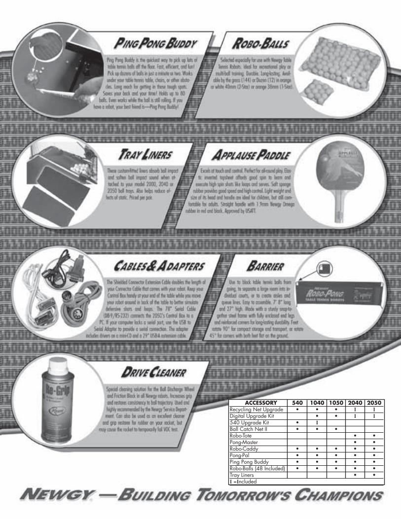
accessOry 540 1040 1050 2040 2050 Recycling Net Upgrade • • • I IDigital Upgrade Kit • • I I540 Upgrade Kit • I Ball Catch Net II • • •Robo-Tote • •Pong-Master • •Robo-Caddy • • • • •Pong-Pal • • • • •Ping Pong Buddy • • • • • Robo-Balls (48 Included) • • • • •Tray Liners • •I =Included
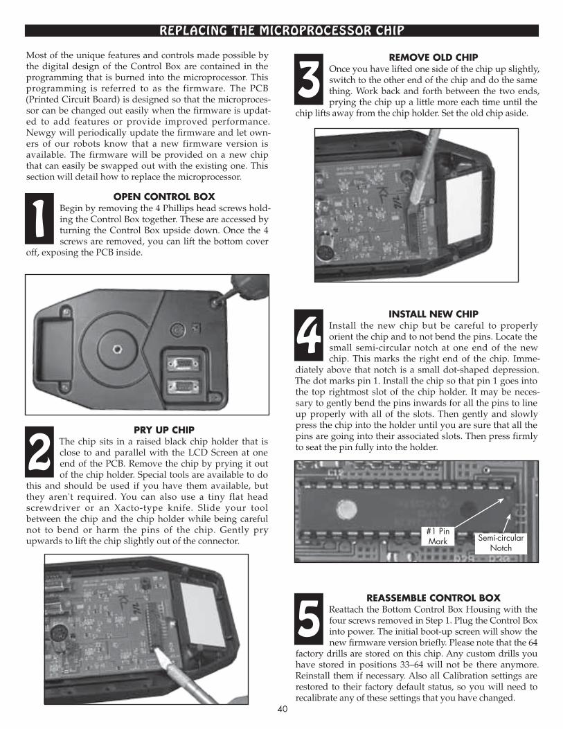
40
Open cOntrOl BOxBegin by removing the 4 Phillips head screws hold-ing the Control Box together. These are acces sed by turning the Control Box upside down. Once the 4 screws are removed, you can lift the bottom cover
off, exposing the PCB inside.
pry up chipThe chip sits in a raised black chip holder that is close to and parallel with the LCD Screen at one end of the PCB. Remove the chip by prying it out of the chip holder. Special tools are available to do
this and should be used if you have them available, but they aren't required. You can also use a tiny flat head screwdriver or an Xacto-type knife. Slide your tool be tween the chip and the chip holder while being careful not to bend or harm the pins of the chip. Gently pry upwards to lift the chip slightly out of the connector.
remOve Old chipOnce you have lifted one side of the chip up slightly, switch to the other end of the chip and do the same thing. Work back and forth between the two ends, prying the chip up a little more each time until the
chip lifts away from the chip holder. Set the old chip aside.
install new chipInstall the new chip but be careful to properly orient the chip and to not bend the pins. Locate the small semi-circular notch at one end of the new chip. This marks the right end of the chip. Imme-
diately above that notch is a small dot-shaped depression. The dot marks pin 1. Install the chip so that pin 1 goes into the top rightmost slot of the chip holder. It may be neces-sary to gently bend the pins inwards for all the pins to line up properly with all of the slots. Then gently and slowly press the chip into the holder until you are sure that all the pins are going into their associated slots. Then press firmly to seat the pin fully into the holder.
reassemBle cOntrOl BOxReattach the Bottom Control Box Housing with the four screws removed in Step 1. Plug the Control Box into power. The initial boot-up screen will show the new firmware version briefly. Please note that the 64
factory drills are stored on this chip. Any custom drills you have stored in positions 33–64 will not be there anymore. Reinstall them if necessary. Also all Calibration settings are restored to their factory default status, so you will need to recalibrate any of these settings that you have changed.
RePLAcINg The mIcRoPRocessoR chIP
1
2
3
4
5
Most of the unique features and controls made possible by the digital design of the Control Box are contained in the programming that is burned into the microprocessor. This programming is referred to as the firmware. The PCB (Printed Circuit Board) is designed so that the microproces-sor can be changed out easily when the firmware is updat-ed to add features or provide improved perfor mance. Newgy will periodically update the firmware and let own-ers of our robots know that a new firmware version is available. The firmware will be provided on a new chip that can easily be swapped out with the existing one. This section will detail how to replace the microprocessor.
#1 PinMark Semi-circular
Notch

41
TRoubLeshooTINg guIDenOtes: 1. The first step to resolve any unusual behavior from the robot is to unplug from power and then re-plug into power. If that doesn't resolve the problem, restore settings to factory default (see page 14) before trying other solutions. 2. There are no adjustments to any part, so if a faulty or worn part causes the robot to malfunction, replace that part. 3. If you are not well-skilled at soldering, please send in your Control Box for service when soldering is indicated. Control Box parts are small and easily damaged. Improper soldering may void your warranty and service policy. 4. If the suggestions below do not help, please check our website for an updated copy of this manual. It can be downloaded from http://www.newgy.com/support-downloadable-instructions-manuals.aspx. 5. The following solutions will apply to all models of Newgy Robots, except if marked with the following footnotes: 1Robo-Pong 1050 only, 2Robo-Pong 2050 only.
No PoweR PRobLems
1. PROBLEM No robot functions work and Control Box does not display
anything. SOLUTIONSA. Make sure Transformer is plugged securely into a
power outlet. Verify the outlet is working.B. Check that the plug on the end of the Transformer cord
is securely plugged into the Control Box power jack.C. Check that the Socket Adapter is securely connected to
the Transformer Main Body. See page 37. D. If A and B are true, the Transformer may be damaged.
If possible, test with voltmeter. Nominal output is 15vdc ± 0.75 volt.
E. If recently exposed to shock, the Control Box may have an internal broken connection. Replace or send in for repair to an authorized service center.
F. The main chip may be loose or damaged. Press the chip firmly into its socket. Replace if damaged (see page 40).
G. See Problem 17.2. PROBLEM No robot functions work or work sporadically and the
Control Box screen displays normally or is garbled. SOLUTIONSA. Reset the Control Box by removing the Transformer
plug, waiting several seconds, and plugging it back in.B. Make sure the Connector Cable is securely plugged in
at both ends. To help prevent the Connector Cable from loosening, wrap cable around the Control Box Mounting Bracket. See Figure 20, page 34.
C. Control Box is damaged. See Solution 11C.D. Connector Cable is damaged. See Solution 11B.
bALL feeD/fReQueNcy PRobLems
3. PROBLEM Robot will not pick up balls. SOLUTIONSA. If the LCD Screen indicates a ball jam, see Problem 16.B. Ball Feed Transfer Gears (47) and/or Main Gear (44)
are damaged or assembled incorrectly. See Figure I, page 45 for correct assembly. Replace gears with strip-ped teeth or other damage.
C. Pickup Fingers (46) and/or Ball Feed Springs (48, 50, & 52) are loose or broken. See Figure I, page 45 for correct assembly. If loose, tighten; if broken, replace.
D. The robot is not fully or correctly seated in the Center Trough2 (1)/Ball Bucket1 (36). Loosen the two Wing Nuts (32) securing the robot body, reposition the robot
body so that it is fully seated. Retighten the wing nuts. See Figure 14, page 19.
E. Ball Feed Motor (49) runs backward. See Problem 10.F. Ball Feed Main Gear (44) is frozen to shaft of Ball Feed
Mounting Plate (42). Replace gear and plate. See Fi gure I, page 45.
G. Ball jam. See Problem 16.H. Ball Feed Motor (49) isn't running. See Problem 11.I. If ball feed stops after 3-6 balls thrown, Ball Sensor is
damaged. Replace. See Figure H, page 45.4. PROBLEM Robot frequently shoots two balls at once. SOLUTIONSA. The Ball Feed Sensor (40) is damaged, not being acti-
vated or its calibration value is incorrect and needs adjustment. Check that wiring to sensor is sound. Verify that the microchip is fully seated in its chip holder on the PCB (see page 40). Refer to SENSOR CALIB on page 12 for explanation of sensor function, calibration and further troubleshooting.
B. Connector Cable is damaged. See Solution 11B.C. The Ball Discharge Spring (58) is broken or worn out.
Replace with a new spring. See Figure D, page 44.D. Robot Head is tilted beyond normal range. If head
angle is less than 1, change to more than 1.E. Using dirty balls or balls of the wrong size. Wash and
dry dirty balls. Check balls with a Ball Dam2 to be sure they are of the correct size and roundness. See page 17.
bALL sPeeD/DIschARge PRobLems
5. PROBLEM Ball speed seems to be slower than when new. SOLUTIONSA. If in Drill Mode, check SPEED ADJUST. See page 10.B. The Ball Discharge Wheel (78) and/or Friction Block (79)
are dirty or worn. Clean these parts periodically accord-ing to the instructions on page 37. If worn, calibrate ball speed to compensate. See SPEED CALIB on page 13. If calibration does not resolve the problem, replace both parts at the same time. See Figures C & D, page 44.
C. The Ball Speed Motor (75) has hair or fibers entwined around its drive pin. Clean, if necessary. See Figure C, page 44.
D. Ball Speed Motor (75) requires lubrication and clean-ing. See Solution 11E.
E. Balls are too small or dirty. Check size with the Ball Dam2 (page 17). Clean balls in warm soapy water. Then rinse in clear water and dry.
F. The brass shaft of the Ball Speed Motor (75) is loose. This shaft is permanently pressed onto the motor's

42
drive pin. It cannot be reattached. Replace the motor. Test by holding the rubber wheel with a finger and without letting go, turn power on and adjust Ball Speed to 30. If you hear the motor spinning while holding the wheel stationary, then the brass shaft is loose. If the motor does not spin, then the shaft is securely fastened.
6. PROBLEM Robot picks up balls, but balls just fall out of discharge open-
ing instead of shooting out. SOLUTIONSA. Ball Speed set to zero. Set to 1 or higher. B. Ball Discharge Wheel (78) is broken or very worn.
Replace. See Figure C, page 44.C. Balls are too small. See Solution 7F.D. Ball Speed Motor (75) isn't running. See Problem 11.7. PROBLEM Robot shoots erratically. Some balls delivered high, others
low or off to the side or ball speed changes without changing BALL SPEED value.
SOLUTIONSA. Verify that no randomization of ball speed is being used.
See SPEED RANDOM (p. 9) or if Drill Mode, check drill for speed randomization with Robo-Soft (p. 32).
B. See Solution 5B.C. Balls are dirty or dusty. Clean balls in warm soapy
water. Then rinse in clear water and dry. D. See Solutions 11F and 12E.E. Control Box component failure. Replace or have ser-
viced by authorized service center. F. Check for correct ball size and roundness (see Figure 11,
page 17). Only 40mm balls can be used. G. Ball Speed Motor mounting screws (91) are loose.
Tighten. See Figure C, page 44.H. Slots in Robot Head Housings for Friction Block tabs
are worn. Replace housings. See Figure D, page 44.
oscILLAToR PRobLems
8. PROBLEM Balls are not delivered to the correct position. SOLUTIONSA. Calibrate the oscillation. See OSC CALIB, page 12. If
oscillator won't calibrate, check for correct assembly of the Oscillator Drive Pin (83) to the Servo (85). See Figures A & B, page 44. Also watch video at http://www.newgy.com/troubleshooting.html
B. Check status of OSC RANDOM. See page 9.C. Set the HAND option to match your dominate hand.
See HAND, page 12.D. Servo may be worn or damaged. Replace with new
unit and recalibrate. See Figure B, page 44 and OSC CALIB on page 12.
E. Be sure robot is centered along end of table. If using a 2050, center rib of Front Support Plate (5) should align with centerline of table. If using a 1050, robot should be positioned at junction of centerline and endline. See Robot Position 1, Figure 12, page 18.
F. Connector Cable is loose. See Solution 2B.G. Be sure Clear Front Cover (53) is properly attached.
See Solution 16C.9. PROBLEM Head does not move between shots.
SOLUTIONSA. Check that L POSITION and R POSITION are set to
different values to enable oscillation movement. B. Something is obstructing the head's movement, possi-
bly the Ball Speed Coiled Power Wire (76). Turn off robot, clear any obstruction and try again.
C. Servo (85) may be worn or damaged. See Solution 8D.D. Check connection between the Servo wire and the
Oscillator Power Wire (86) at top of Upper Guide (54). If loose, connect securely.
E. Be sure oscillator parts are properly aligned. See Fi -gure A & B, page 44 for proper alignment.
F. Servo isn't running. See Solutions 11A, B, C, and D.
geNeRAL moToR PRobLems
10. PROBLEM Ball Speed or Ball Feed Motor runs backward (clockwise). SOLUTIONSA. Connector Cable is loose. Perform Solutions 2A & 2B.B. Broken or intermittent ground circuit in the Connector
Cable. Replace with a known good cable.C. Check that wires are correctly soldered to proper ter-
minal of the corresponding motor. See Figures D & I, pages 44 & 45.
11. PROBLEM One or two motors don't run, but the others run normally. SOLUTIONSA. Connector Cable is loose. See Solution 2B.B. One or more of the wires inside the Connector Cable is
broken. Test with a known good cable if possible or use a voltmeter to check for continuity. Replace if damaged.
C. Control Box is damaged. Test with second Control Box if possible. Or run Self Diagnostics (page 14) and report test codes to service technician. Replace or send in for repair to authorized service center.
D. Robot wiring contains a short or open circuit. Carefully check robot wiring for conductive debris and exposed or broken wires. In particular, check that the power wire for the non-functioning motor is securely soldered to the 5 Pin Connector PCB (89) and that the 5 Pin Connector (88) is securely soldered to the PCB. Also check that the wires are securely soldered to the motor. Replace damaged parts or re-solder loose connections.
E. If the machine has not been used for a while, the motor may be frozen. Set the motor's corresponding Control Box setting at its maximum value. Then rotate the Discharge Wheel (78) or Pickup Wheel (45) by hand. The motor should start running normally. Then lubri-cate with electrical contact cleaner/lubricant while motor is slowly turning.
F. The motor may be worn or damaged. The motor can be tested by touching the motor terminals with the posts of a 9-volt battery. Before testing, disconnect any gears that are connected in sequence to the motor. If the motor does not run from battery power, it must be replaced. Alternatively, run Self Diagnostics (see page 14) and report test codes to service technician. Replace.
12. PROBLEM A motor runs, but does not change speed when the corre-
sponding setting is changed on the Control Box.

SOLUTIONSA. Reset the Control Box. See Solution 2A.B. Control Box component failure. See 11C.C. Connector Cable is loose. See Solution 2B.D. If Servo moves only at full speed, causing the robot to
jerk and jump, see Solution 12B.E. If Ball Speed Motor runs only at full speed or pulsates,
check for a short in the Servo by disconnecting the Servo's wire. If problem goes away, replace the Servo. If the problem remains, replace the Control Box PCB.
DRILL moDe
13. PROBLEM Drills deliver balls too long or too short. SOLUTIONSA. Set SPEED ADJUST to 0.B. Set head angle to match the drill’s recommended set-
ting. Then nudge up or down from given setting to adjust depth of landing spot on table.
C. Verify the robot’s Ball Speed is correctly calibrated. See SPEED CALIB on page 13.
D. Clean Discharge Wheel and Friction Block. See pg. 37.E. Verify that table and robot are level. If short balls are
hitting the net, check net height—it should be 6″ high.14. PROBLEM Drills deliver backhand balls to the forehand side of the table,
or vice versa. SOLUTIONA. HAND is set incorrectly. See page 12.15. PROBLEM There is no Drill Preview for a drill. SOLUTIONA. Not all drills make use of the Drill Preview option. No
Preview is normally provided for a drill that includes randomization of Ball Speed or Position because the landing spots cannot be accurately shown. The drill will still run normally. Consult Drill DiagraMs section (pages 22–27) for more detail and for printed diagrams of ball landing spots. If DRILL # is 33–64, it may be a user-installed drill without documentation or Preview. Check landing spots against drill diagrams. If different, you can restore drills to match those in Drill DiagraMs by using the Set Drills To Factory command in Robo-Soft (see page 29).
bALL jAms
16. PROBLEM Balls jam inside the machine. Ball jams are normally indi-
cated by a beeping noise from the Control Box and the mes-sage—BALL JAM ALARM CHECK BALL CHANNEL—appears on the LCD Screen.
SOLUTIONSA. Make sure the Connector Cable is securely connected
at both ends. The Jam Alarm can be falsely activated if the Control Box does not sense a connection to the robot. In this case, there is no problem inside the ball channel. Securely connect the Connector Cable and the Jam Alarm will go away.
B. Using very dirty balls. Dirty balls may create excess friction as the balls are pushed through the robot and hang up inside the ball channel. Clean balls in warm soapy water, rinse in clear water, and then dry. Also
build-up of dirt on the Friction Block (79) and/or Ball Discharge Wheel (78) can narrow the opening between these parts, denting the balls and/or causing ball jams. Periodically inspect these parts, and if necessary, follow cleaning instructions on page 37.
C. Clear Front Cover (53) is not fully attached. Verify that all four clips of the cover are fully through their slots on the Back Panel. See Figure 21, page 34.
D. Oversized, irregular, dented or damaged balls can cause jams. Inspect balls for proper size by using a Ball Dam2 (see page 17). Remove any abnormal balls or any balls that do not pass easily through this gauge.
E. Foreign objects or loose parts in the ball feed path can also cause jams. Remove the Clear Front Cover (Figure 21, page 34) and remove anything that might be ob struc ting ball flow. Verify that Ball Feed Fingers (46) are attached securely. Also inspect inside the head.
F. Worn or damaged Ball Discharge Spring (58). Open the robot head and inspect the back surface of the spring for wear. Replace if any flat shiny surface is found or the spring is otherwise damaged. Should be completely round with no flat spots. See Figure D, page 44.
G. Ball Speed Motor runs backward. See Problem 10.
LcD scReeN
17. PROBLEM LCD Screen does not display properly—blank screen, gar-
bled text, or screen is stuck. SOLUTIONSA. See Solution 2A.B. Activating a Special Function (see page 13) will cause the
screen to go blank and then turn black. This is normal behavior. Hit the Power button twice to leave Special Function mode without activating a special function.
C. If text is very light and/or background very dark, it is likely that CONTRAST is set incorrectly. Sometimes this may occur unexpectedly and without user involve-ment. Adjust CONTRAST (see page 11) to a more visi-ble setting (10–20) or use the Factory Default Restora-tion special function (see page 14).
D. If screen displays normally when the Connector Cable is disconnected, but goes blank or becomes garbled when the cable is connected, there is likely a short in the electrical system, probably the servo. See Technical Service Bulletin #5 (TSB5) on the Newgy.com website.
E. If screen is displaying in a foreign language that you cannot read, select desired language by following in struc tions for Language Selection, page 13–14.
E. Connect the robot to a PC and run the Set Screen To Factory command in the Device menu of Robo-Soft. This will update the firmware to include fixes for rare instances of blank or garbled screens.
F. If LCD displays "10.5 V" during startup, the Control Box PCB is faulty and needs to be replaced.
G. If LCD slowly fades to black, replace Control Box PCB. May also be accompanied by message, "Wrong voltage, check transformer" before fading.
H. Servo is damaged. See Solution 8D. This type of servo damage can in turn cause Control Box PCB damage (see Solution 12D).
1Robo-Pong 1050 only, 2Robo-Pong 2050 only43

Install Servo (85) into Servo Cover (84) and hook up to power. Before attaching Drive Pin (83) onto Servo, connect robot to Control Box and set OSC CALIB to 25, then press TEST. Now attach Drive Pin to Servo and press TEST again so the pin's pointer points to the centerline mark of the cover as closely as possible (it may not be possible to align it exactly). Then screw the pin onto the servo. Be sure pin's gears and servo's gears mesh properly. After reassembly, perform OSC CALIB.
44
eXPLoDeD vIews, DIsAssembLy, AND RePAIR nOtes: 1. Refer to the following drawings when disassembling or assembling the robot. The key numbers used to identify the parts correspond to the key numbers on the Parts List on pages 46 & 47. 2. There are no adjustments to any robot parts. If there is a faulty or worn part that causes the robot to malfunction, that part must be replaced. Your robot is designed to be easily serviced and repaired. 3. Do not use petroleum based lubricant, solvents, or other chemicals on plastic parts. These chemicals are corrosive
and will cause the plastic to disintegrate.
rOBOt head assemBly
1. When disassembling the robot head, do not let the Steel Ball and Spring (68, 67) fall out of the Left Housing (65), since they’re small and easy to lose! A bit of grease will hold them in place when reas sem bling. Work atop a towel to prevent loss of parts.2. A small amount of Superglue® (cyano-acry late) holds the Ball Discharge Spring (58) onto the Discharge Tube (56). Scrape off old glue before replacing the spring.3. Keep Friction Block (79) and Discharge Wheel (78, Figure C) clean for correct ball speeds. See page 37 for cleaning procedure.
servO cOver, pivOt guide & upper guide alignment
Ball speedmOtOr & wheel
tO hOusing
warning: The screw (81) is left-hand threaded! Loosen by turning clockwise; tighten by turning counter-clockwise.
Osc.alignmentfigure a figure B
figure c
figure dRed Wire Attaches To Terminal With Polarity Marker
When assembling these parts together be sure the Drive Pin of Part 83 fits into the Slot of Part 82. Also be sure that the upper Pivot Pin of Part 82 fits into the corresponding hole of Part 84 and the lower Pivot Pin of Part 82 fits into the corresponding hole of Part 54.
58See Note #2
Drive Pin
UpperPivot Pin
Slot
Hole
Centerline
54
Pointer 8583
87
71
777156
6680
65
75
91
90
83
84
78
81
66
85
84
82
RobotHead
SeeNote #168 67
79See
Note #3
Check for hair or fibers
entwined around motor's
drive pin at base of
brass shaft.
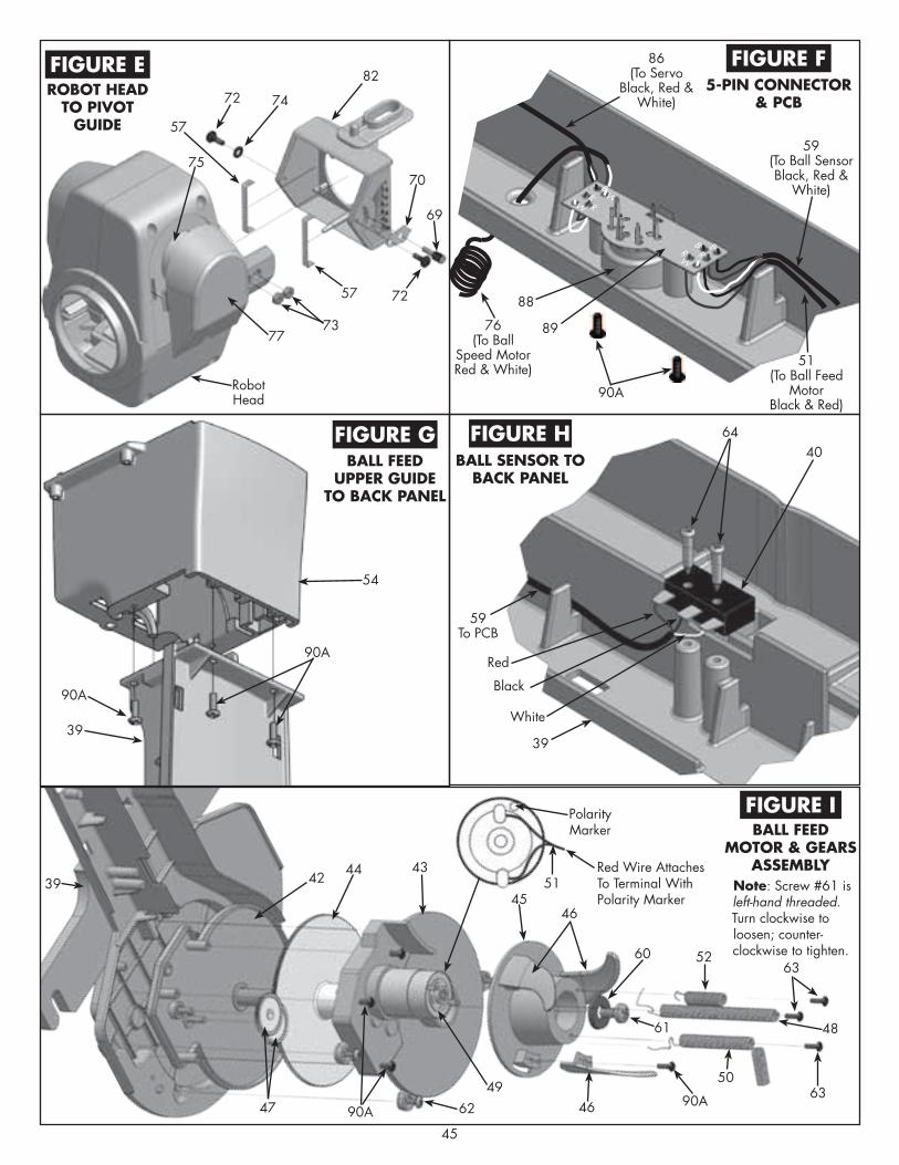
RB
WRR
RW
B
B
W
45
rOBOt head tO pivOt
guide
5-pin cOnnectOr & pcB
Ball feed upper guide
tO Back panel
Ball sensOr tO Back panel
Ball feedmOtOr & gears
assemBly
figure e figure f
figure g figure h
figure i
Red Wire Attaches To Terminal With Polarity Marker
note: Screw #61 is left-hand threaded. Turn clockwise to loosen; counter-clockwise to tighten.
Polarity Marker
76(To Ball
Speed MotorRed & White)
86(To Servo
Black, Red & White)
59(To Ball SensorBlack, Red &
White)
51(To Ball Feed
MotorBlack & Red)
Red
White
RobotHead
Black
82
70
69
72
72
57
57
75
54
39
89
39
50
63
61
90A
60 52
46
51
4645
4342
62
3944
4749
90A
48
63
88
90A
90A
90A
40
7377
74
59To PCB
64

key# part # item Qty.
1 2000-100 center trough 1 2 2000-101 CT Rubber Feet 4 3 2000-102 CT U-Shaped Support Tube 1 4 2040-103 CT Wedge Filler 1 5 2000-104 CT Support Plate, Front 1 6 2000-106A CT Front Support Plate Pad (not shown) 1 7 2000-108 CT Support Plate, Back 1 8 2000-110 CT Support Leg, L 1 9 2000-112 CT Support Leg, R 1 10 2000-114 CT Support Leg Rubber Tip, 1/2″ 2 11 2000-116 CT Support Leg Rubber Tip, 3/4″ (std.) 2 12 2000-118 CT Support Leg Rubber Tip, 1″ 2 13 2000-120 CT Rubber Spacer-Washer (not shown) 4 14 2000-122 CT Pivot Pin 1 15 2050-124 CT Ball Dam, 40mm 2 16 2040-126A net, 40mm 1 17 This part is no longer used 1 18 2000-128 Net Support Tube, Straight 2
PARTs LIsT foR NeT AssembLy (2050 oNLy)
key# part # item Qty.
19 2000-130 Net Support Tube, Curved, L & R 2 19A 2000-131 Net Support Tube Plug 3 20 2000-132 Net Support Tube, Curved, Center 1 21 2000-134 Net Support Plate, Front 1 22 2000-136 Net Support Plate, Back 1 23 2000-138 Ball Return Tray 2 24 2000-140A Carrying Strap 1 25 2000-300 Net Retaining Screw 3 26 2000-302 #8 x 1″ Machine Screw 8 27 2000-304 #8 x 3/4″ Machine Screw 6 28 2000-306 #8 x 1/2″ Machine Screw 1 29 2040-307 #8 x 5/8″ Machine Screw 1 30 2000-308 #8 x 1″ Hex Bolt 2 31 2000-310 #8 Hex Nut 16 32 2000-312 Wing Nut 2 33 2000-314 Large Washer 4 34 2000-315 Clip Washer 2 35 2000-316 #8 x 3/8″ Machine Screw 1
nOte: The key numbers on this parts list correspond to the numbers used to identify parts in this manual.
46
30
32
14
9
10,11,125
24
2
4
33
16
20
18
33
15
34
7
8
23
23
31
3131
31
21
22
2635
27
29
27
28
1
17
17
19
19
19A
19A19A
25
25
25
18
3

key# part # item Qty. 36 1040-100 Ball Bucket1 1 37 1040-101 Ball Bucket Pad1 1 38 1040-105 Bucket Extender1 1 39 2050-142 Ball feed Back Panel, 40mm 1 40 2050-143 BF Ball Sensor 1 41 2000-144A BF Collector Plate2 1 42 2050-145 BF Mounting Plate 1 43 2040-147 BF Top Cap, 40mm 1 44 2050-149 BF Main Gear 1 45 2040-151B BF Pickup Wheel, 40mm 1 46 2040-153A BF Pickup Finger, 40mm 3 47 2050-155 BF Transfer Gear 2 48 2050-157 BF Spring, Long 1 49 2050-158 BF Motor w/Gear 1 50 2050-159 BF Spring, Medium 1 51 2000-160A BF Power Wire (Figs. F & I, pg. 45) 1 52 2040-161A BF Spring, Short (Fig. I, pg 45) 1 53 2040-162A BF Clear Front Cover, 40mm 1 54 2050-164 BF Upper Guide, 40mm 1 55 2050-165 BF Upper Guide Cover 1 56 2050-166 BF Discharge Tube, 40mm 1 57 2000-168 BF Discharge Tube Brake 2 58 2000-170A BF Discharge Spring (Fig. D, pg. 44) 1 59 2050-171 BF Ball Sensor Power Wire (Fig. F, p. 45) 1 60 2050-313 BF Pickup Wheel Washer 1 61 2050-317 BF Pickup Wheel Screw (LH Thread) 1 62 2000-318 BF #4 x 5/16″ Machine Screw 4 63 2040-319 BF Spring Screw 3 64 2050-327 BF Ball Sensor Screw 2 65 2050-172 robot head Housing, L, 40mm 1 66 2050-174 RH Housing, R, 40mm 1 67 2000-176 RH Steel Ball 1 68 2040-178 RH Steel Ball Spring 1 69 2050-180 RH Angle Adjustment Knob, 40mm 1 70 2050-182 RH Angle Pointer 1 71 2000-320 RH #8 x 13/16″ Machine Screw 4 72 2040-321 RH Pivot Screw 2 73 2040-323 RH Pivot Screw Nut 3 74 2050-329 RH Pivot Screw Washer 1 75 2000-184 Ball speed Motor w/Brass Shaft (Fig C) 1 76 2000-186B BS Coiled Power Wire (Fig. F, Pg. 45) 1 77 2000-188 BS Motor Cover 1 78 2000-190 BS Discharge Wheel (Fig. C, Pg. 44) 1 79 2040-192A BS Friction Block, 40mm 1 80 2050-193 BS Friction Block Bushing 1 81 2000-324 BS Discharge Wheel Screw (LH Thread) 1 82 2050-196 Oscillator Pivot Guide, 40mm 1 83 2050-199 Osc. Drive Pin 1 84 2050-204 Osc. Servo Cover 1 85 2050-209 Osc. Servo 1 86 2050-210 Osc. Power Wire w/Connector (Fig. F) 1 87 2050-325 Osc. Drive Pin Screw (Fig. B, Pg. 44) 1 88 2050-218 5-Pin Connector 1 89 2050-219 5-Pin Connector PCB (Fig. F, Pg. 45) 1 90 2000-328 #5 x 3/8″ Thread Cutting Screw 3 90A 2000-328A #5 x 3/8″ Thread Cutting Screw 161/192
91 2000-330 #2 x 1/4″ Machine Screw (Fig. C, Pg. 44) 4 92 2050-220 Shielded Connector Cable (not shown) 1
47
PARTs LIsT foR RoboT boDy AssembLy & bALL buckeT
key# part # item Qty.
93 2050-222 Transformer Main Body (not shown) 1 94 2050-223 Transformer Socket Adapter (see Pg. 37) 1 95 2050-224 Control Box (see Pg. 6) 1 96 2050-226 Control Box Bracket (see #8, Pg. 4) 11Robo-Pong 1050 only; 2Robo-Pong 2050 only
41(2050ONLY)
90A
90A
71
56
66
65
67
57
90A
90A
39
88
82
7269
79
80
68
7274
70
84
9087
85
54
83
53
38
48
49
90A
34
34
12
4042
45
50
62
43
361050 ONLY
6044
61
37
32
47
46
77
90A30

Owner's manual
table tenniS rObOtservice and repair
hOw tO Order replacement parts
service pOlicy
warranty
LIMITED 1 YEAR WARRANTYManufacturer warrants to the original retail purchaser this product to be free from defects in material and workmanship for a period of 1 year from date of purchase.
Should this product become defective due to material or workmanship during the warranty period, contact our Customer Service Department describing the defect. Always provide your serial number. We will provide you with return authorization and shipping instructions. If you are asked to return the product, pack it securely and ship it PREPAID.
If defective as provided by the terms of this warranty, we will, at our option, repair or replace the product and return it prepaid to a continental U.S. address (other areas carry a shipping charge).
This warranty is not transferable and does not cover normal wear and tear, or damage caused by improper handling, installation, or use. This war-ranty is void if the product is in any way abused, damaged, or modified from its original state.
This warranty gives you specific legal rights, and you may have other rights that may vary from state to state.
Thank you for purchasing a Newgy Robo-Pong robot. We inspect our prod-ucts to be sure they are of high quality and free of defects. However, if you need service or advice on your robot, please contact our Customer Service Department. The information below is applicable only to Newgy customers in North and South America. If you are in another area of the world, please contact the distributor for your area for service polices for your area. A list of distributors can be found at Newgy.com.
Please call us for return authorization before you send in your robot for repair. Often, repairs can easily be handled on the phone. Have you tried to troubleshoot the problem by trying the tips on pages 41–43 or performing a Factory Default Restoration (pg. 14)? You may also want to visit our website to see if any information has been updated. When you do call, please have your serial number and this manual handy. (The serial number is located on the Support Flange—see Fig. 14, pg. 19.) If, after talking with our Service Department, you need to send in your robot, include a brief note describing the problem and listing your daytime phone number and shipping address.
If you know which part you want to order (see pages 46 & 47), you may order it by phone if you have a credit card (Visa, MasterCard, American Express, or Discover). Otherwise, please fill in a parts order form (available online) and mail it, along with a check or money order, to Newgy.
OUT OF WARRANTY SERVICE POLICY: When your 1 Year Limited Warranty expires, Newgy will repair any normal wear and tear to the robot for a $40 service charge plus $10 shipping and handling (for continental U.S., other areas carry additional fees) for a period of 5 years from date of pur-chase. This policy does not cover damage due to abuse, misuse, or improper handling and applies only to the original retail purchaser of Newgy robots bought from the USA.
Your Warranty Card (included with this manual) should be mailed with-in 15 days of purchase. A copy of the warranty information is given below. Be sure to keep your purchase receipt. We suggest you keep your receipt with this manual and record the following information:
Date Purchased _____________________ Serial # ________________________
Store Name ________________________ City, State ______________________Record any custom SETUP values below to quickly re-store these settings after using Factory Default Restoration (see page 14).
CONTRAST _______________
OSC CALIB _______________
SENSOR CALIB ___________
ALARM CALIB ___________
SPEED CALIB _____________