New structure of PV module type approval and safety … · 2019-03-28 · - Attempt to extend...
88
Normative Neustrukturierung der Typ- und Sicherheitsprüfung von PV-Modulen aller Technologien New Structure of PV Module Type Approval and Safety Qualification Standards TÜV Rheinland Workshop "Update of IEC standards for PV modules„ Kuala Lumpur, Malaysia, 21 st March 2017 March 17 1 New structure of PV module type approval and safety qualification standards
Transcript of New structure of PV module type approval and safety … · 2019-03-28 · - Attempt to extend...

Normative Neustrukturierung der Typ-und Sicherheitsprüfung von PV-Modulenaller Technologien
New Structure of PV Module Type Approval and Safety Qualification StandardsTÜV Rheinland Workshop "Update of IEC standards for PV modules„ Kuala Lumpur, Malaysia, 21st March 2017
March 171 New structure of PV module type approval and safety qualification standards

Disclaimer
This presentation was originally prepared based on draft versions of the InternationalElectrotechnical Commission standards IEC 61215 and IEC 61730 published in 2016.
TÜV Rheinland Energy GmbH (TRE) endeavors to ensure that the information providedin this presentation is correct and up-to-date. Nevertheless, errors and ambiguitiescannot be completely excluded. TRE does therefore not warrant the up-to-dateness,correctness, completeness or quality of the provided information.
Publication or transfer of this document to third parties is only permissible in itscomplete an unabridged form. Publication or dissemination of extracts, appraisals orany other revision and adaptation hereof, in particular for advertising purposes, is onlypermissible on receipt of prior written agreement by TÜV Rheinland.
March 17 New structure of PV module type approval and safety qualification standards2

Basic understanding of the recent modifications of the IEC guidelines for PV modules
Review of IEC 61215:2016 (type approval) - general requirements and test methods
Review of IEC 61730-1:2016 (safety qualification) - requirements for construction
Review of IEC 61730-2:2016 (safety qualification) - requirements for testing
Transitional periods
Closing remarks
Content
March 17 New structure of PV module type approval and safety qualification standards3

Recent modifications of IEC guidelines: History
1975-1981: JPL ‘Block Buys’ I-V (c-Si)- Based on NASA tests for space applications
- Temperature cycles (-40°C to +90°C)
- Mechanical load, hail and isolation test intro-duced in Block V
- Outdoor exposure mainly in the US deserts
- Block VI cancelled due to budget cuts in Reagan administration
March 17 New structure of PV module type approval and safety qualification standards4
Images taken from “Experience in Design and Test of Terrestrial Solar-Cell Modules”; Smokler and Runkle, Texas, 1982

Recent modifications of IEC guidelines: History
1981-1991: ESTI (European Solar Test Installation, Italy) – EU Specification 501 to 503
- Based on JPL Block V additional with UV and outdoor exposure; maximum temperature reduced to 85°C
- EU 503 was the basis for IEC (6)1215
1990: SERI IQT modifications for TF (a-Si)- SERI: Solar Energy Research Initiative
- Wet leakage current test
- Bypass diode test
- Scratch test (ANSI/UL 1703)
- Ground continuity test (ANSI/UL 1703)
1993: IEC (6)1215 Ed. 1 (c-Si)- Combination of all available test methods
1995-2000: IEEE 1262 – all technologies- Combination of IQT and IEC (6)1215
March 17 New structure of PV module type approval and safety qualification standards5

Recent modifications of IEC guidelines: History
1996: IEC (6)1646 Ed. 1 (TF – a-Si)- Based on IEEE 1262 plus light-soaking and annealing
1996: TÜV Spec TZE/2.572.09 − Safety class II Test on Photovoltaic (PV) Modules
2004: IEC 61730 Ed. 1 (c-Si & TF)- Photovoltaic (PV) module safety qualification
- Application class A, safety class II
- safe electrical and mechanical operation
2005: IEC 61215 Ed. 2 (c-Si)- Wet leakage current test taken from IEC 61646
- Bypass diode test taken from IEEE 1262
- Current flow during Thermal cycling test introduced
2008: IEC 61646 Ed. 2 (TF – a-Si, CdTe, CIGS)- Attempt to extend validity to new TF technologies (CdTe, CIGS)
- Adapted pass/fail criteria to final power after stress tests
- Adapted Hot-spot test method, Bypass diode test introduced
March 17 New structure of PV module type approval and safety qualification standards6

Recent modifications of IEC guidelines
Alignment of requirements for crystalline Si and various thin-film technologies
No differentiation in minimum requirements
Clear structure with
- general requirements
- test methods
- technology specific parts
Consistence with other international standards
Possibility to react quickly to new technology developments with individual standard parts
IEC 61215-1, -1-1 and -2 published in March 2016
Thin-film parts IEC 61215-1-2 through 1-4 published in December 2016
Other technology specific parts (-1-x) are being developed
March 17 New structure of PV module type approval and safety qualification standards7
Motivation for the adaption of the IEC 61215 standard structure

Recent modifications of IEC guidelines
IEC 61730 has always been a bad compromise between EU guidelines and ANSI/UL 1703.
Many outdated test requirements, imperfect formulations and (too) much room for interpretation
Adaption to meet general IEC guidelines for standard structures
Alignment with general „horizontal“ standards, e.g. IEC 60664
Consideration of new technology developments
Full extension to 1500 V DC system voltage
Incorporation of existing component standards- Cable EN50618 (IEC 62930 is under development, will replace EN 50618)
- Connector IEC 62852
- Junction box IEC 62790
IEC 61730-1 and -2 published in August 2016
March 17 New structure of PV module type approval and safety qualification standards8
Motivation for the rework and restructuring of IEC 61730

Basic understanding of the recent modifications of the IEC guidelines for PV modules
Review of IEC 61215:2016 (type approval) - general requirements and test methods
Review of IEC 61730-1:2016 (safety qualification) - requirements for construction
Review of IEC 61730-2:2016 (safety qualification) - requirements for testing
Transitional periods
Closing remarks
Content
March 17 New structure of PV module type approval and safety qualification standards9

Review of IEC 61215:2016 (type approval)
March 17 New structure of PV module type approval and safety qualification standards10
Part 2 – Test Methods
Part 1-1 c-Si
Part 1-2 CdTe
Part 1-3 a-Si & µ-Si
Part 1-4 CIS&CIGS
Part 1-x New technologies
.........
IEC 61215 Ed. 2 Requirements
IEC 61215 Ed. 2 Test Methods
IEC 61646 Ed. 2 Requirements
IEC 61646 Ed. 2 Test Methods
New IEC 61215 seriesPrevious status
Part 1 – General Requirements
Review of IEC 61215:2016
March 17 New structure of PV module type approval and safety qualification standards11
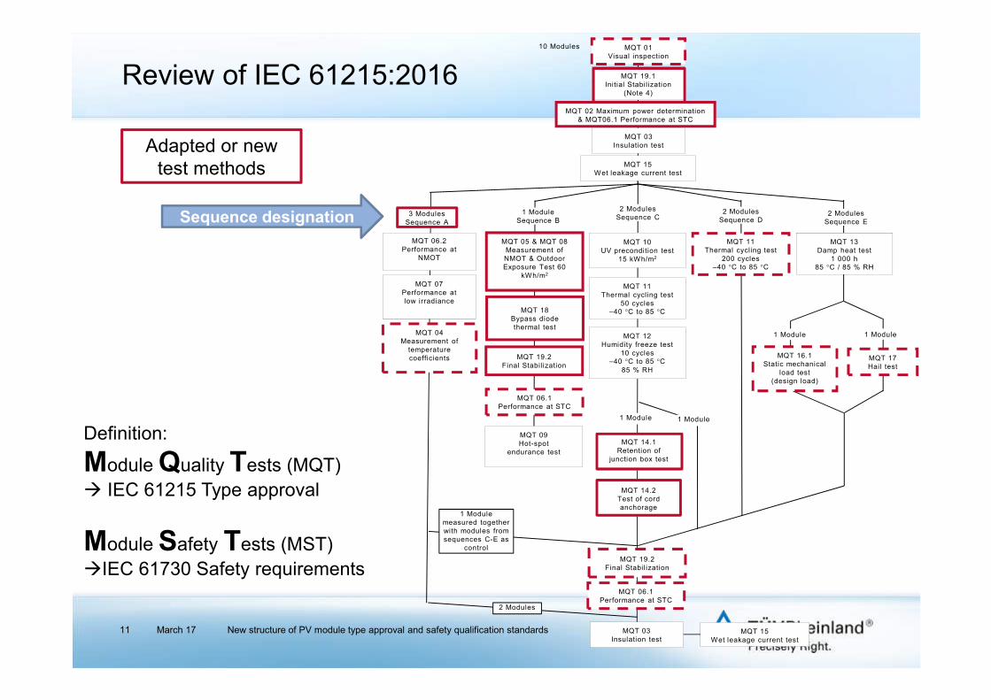
Adapted or new test methods
Sequence designation
Definition:
Module Quality Tests (MQT) IEC 61215 Type approval
Module Safety Tests (MST) IEC 61730 Safety requirements
MQT 01Visual inspection
MQT 02 Maximum power determination & MQT06.1 Performance at STC
MQT 03Insulation test
MQT 15Wet leakage current test
MQT 10UV precondition test
15 kWh/m2
MQT 11Thermal cycling test
50 cycles–40 °C to 85 °C
MQT 12Humidity freeze test
10 cycles–40 °C to 85 °C
85 % RH
10 Modules
MQT 15Wet leakage current test
1 Module
MQT 06.2Performance at
NMOT
MQT 07Performance atlow irradiance
MQT 04Measurement of
temperature coefficients
MQT 19.1Initial Stabil ization
(Note 4)
MQT 06.1Performance at STC
3 ModulesSequence A
1 ModuleSequence B
2 ModulesSequence C
2 ModulesSequence D
2 ModulesSequence E
MQT 19.2Final Stabil ization
MQT 05 & MQT 08Measurement of NMOT & Outdoor Exposure Test 60
kWh/m2
MQT 18Bypass diodethermal test
MQT 09Hot-spot
endurance test
MQT 16.1Static mechanical
load test(design load)
MQT 17Hail test
1 Module1 Module
MQT 11Thermal cycling test
200 cycles–40 °C to 85 °C
MQT 13Damp heat test
1 000 h85 °C / 85 % RH
MQT 14.1Retention of
junction box test
1 Module
MQT 19.2Final Stabil ization
MQT 06.1Performance at STC
1 Modulemeasured together with modules from sequences C-E as
control
2 Modules
MQT 14.2Test of cord anchorage
MQT 03Insulation test
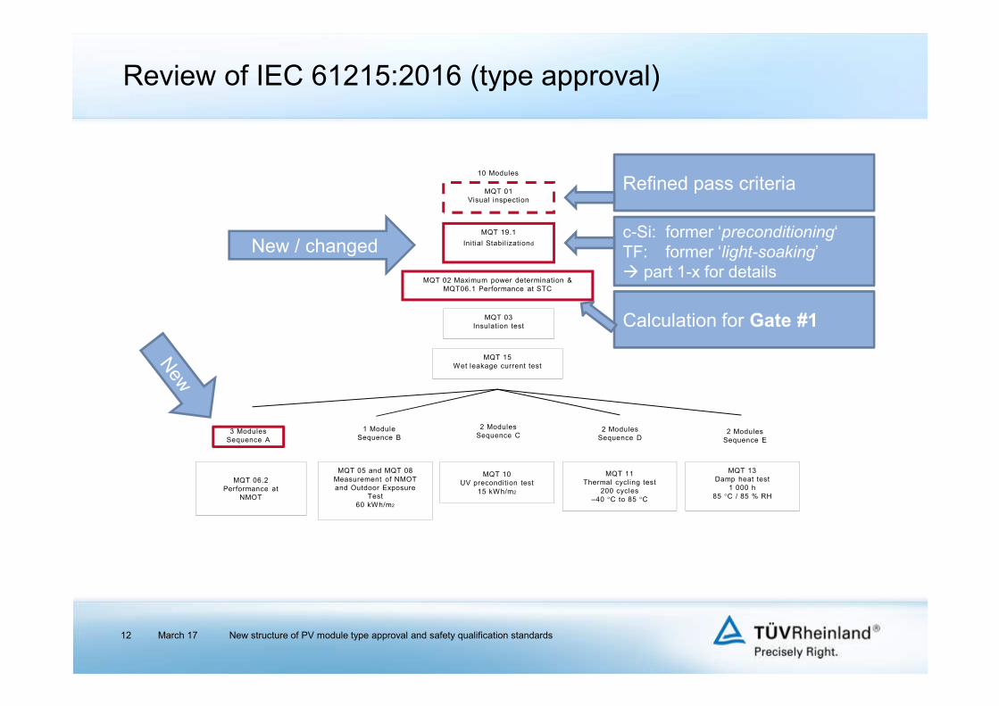
Review of IEC 61215:2016 (type approval)
March 17 New structure of PV module type approval and safety qualification standards12
MQT 01Visual inspection
MQT 02 Maximum power determination & MQT06.1 Performance at STC
MQT 03Insulation test
MQT 15Wet leakage current test
MQT 10UV precondition test
15 kWh/m2
10 Modules
MQT 06.2Performance at
NMOT
MQT 19.1
Initial Stabil izationd
3 ModulesSequence A
1 ModuleSequence B
2 ModulesSequence C
2 ModulesSequence D
2 ModulesSequence E
MQT 05 and MQT 08Measurement of NMOT and Outdoor Exposure
Test60 kWh/m2
MQT 11Thermal cycling test
200 cycles–40 °C to 85 °C
MQT 13Damp heat test
1 000 h85 °C / 85 % RH
New / changed
Refined pass criteria
c-Si: former ‘preconditioning‘ TF: former ‘light-soaking’ part 1-x for details
Calculation for Gate #1

Review of IEC 61215:2016 (type approval)
March 17 New structure of PV module type approval and safety qualification standards13
Changed and separated into two sequences (A+B)
MQT 06.1 and 06.2 with clear
separation
NMOT (former NOCT): Nominal Module Operating TemperatureImprovement of data base
MQT 10UV precondition test
15 kWh/m²
MQT 11Thermal cycling test
50 cycles–40 °C to 85 °C
MQT 12Humidity freeze test
10 cycles–40 °C to 85 °C
85 % RH
MQT 06.2Performance at
NMOT
MQT 07Performance atlow irradiance
MQT 04Measurement of
temperature coefficients
3 ModulesSequence A
1 ModuleSequence B
2 ModulesSequence C
2 ModulesSequence D
2 ModulesSequence E
MQT 05 and MQT 08Measurement of NMOT and Outdoor Exposure
Test60 kWh/m²
MQT 18.1Bypass diodethermal test
MQT 16Static mechanical
load test(design load)
MQT 17Hail test
1 Module1 Module
MQT 11Thermal cycling test
200 cycles–40 °C to 85 °C
MQT 13Damp heat test
1 000 h85 °C / 85 % RH
MQT 19.2Final Stabil ization
MQT 06.1Performance at STC
c-Si: not requiredTF: former ‘light-soaking’
part 1-x for details

MQT 15Wet leakage current test
1 Module
MQT 06.1Performance at STC
MQT 19.2Final stabil ization
MQT 09Hot-spot
endurance test
MQT 14.1Retention of junction
box test
1 Module
MQT 14.2Test of cord anchorage
MQT 03Insulation test
MQT 18.2Bypass diode
functionality test
Review of IEC 61215:2016 (type approval)
March 17 New structure of PV module type approval and safety qualification standards14
c-Si: not requiredTF: former ‘light-soaking’
part 1-x for details
Changed from 10.2 (MQT 02) to MQT 06.1 to clarify that STC measurement is requiredCalculation for Gate #2
Adapted and refined test method:former ‘Robustness of
Terminations test’

Review of IEC 61215:2016 (type approval)
March 17 New structure of PV module type approval and safety qualification standards15
Gate #1: Type label power assessment (pass criteria at the begin of a sequence;Clause 7 of IEC 61215-1) Confirmation of nominal output power of type label including tolerances
Pmax (NP): Nominal power (name plate)- : negative tolerance of NP + : positive Tolerance of NP
MQT 19 of part 1-x
Pass: Measured power incl. measurement uncertainty (MU) lays within the given tolerances.
Fail: One or more modules have a power outside the given tolerances after consideration of the measurement uncertainty.
MQT 06.1
low high- +
Pmax(NP)
- +
Pmax(NP)
- +
Pmax(NP)
PassPmax(Label)
low high- + - + - +
Faillow high- +
Pmax(NP)
- +
Pmax(NP)
- +
Pmax(NP)

Review of IEC 61215:2016 (type approval)
March 17 New structure of PV module type approval and safety qualification standards16
Example:Module family for certification: power classes 180 W to 220 W and tolerance ± 3 %
Passed
MQT 19 of part 1-x
MQT 06.1
Lower class: 180 W Highest class: 220 W
V
Pmax(NP)
- + V
Median class: 200 WPmax(NP)
- +
Pmax(NP)
- +
V- + V- + - +
174.6 W 185.4 W 194.0 W 206.0 W 213.4 W 226.6 W
174.6 W 185.4 W 194.0 W 206.0 W 213.4 W 226.6 W

Review of IEC 61215:2016 (type approval)
March 17 New structure of PV module type approval and safety qualification standards17
Example:Module family for certification: power classes 180 W to 220 W and tolerance ± 3 %
MQT 19 of part 1-x
Lower class: 180 W Highest class: 220 W
V
Pmax(NP)
- + V
Median class: 200 WPmax(NP)
- +
Pmax(NP)
- +
V- + V- + - +
174.6 W 185.4 W 194.0 W 206.0 W 213.4 W 226.6 W
174.6 W 185.4 W 194.0 W 206.0 W 213.4 W 226.6 W
MQT 06.1 Failed
Review of IEC 61215:2016 (type approval)
March 17 New structure of PV module type approval and safety qualification standards18
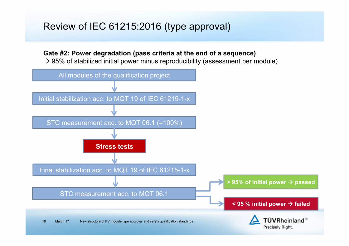
All modules of the qualification project
Stress tests
> 95% of initial power passed
< 95 % initial power failed
Gate #2: Power degradation (pass criteria at the end of a sequence) 95% of stabilized initial power minus reproducibility (assessment per module)
Initial stabilization acc. to MQT 19 of IEC 61215-1-x
STC measurement acc. to MQT 06.1 (=100%)
Final stabilization acc. to MQT 19 of IEC 61215-1-x
STC measurement acc. to MQT 06.1

Review of IEC 61215:2016 (type approval)
March 17 New structure of PV module type approval and safety qualification standards19
General requirements and regulations (IEC 61215-1)
IEC norms can be taken as basis for low concentrator modules (1-3 suns)
If several power classes to be approved (within the limits of IEC/TS 62915): 2 modules to be taken from lower and upper end and from median of distribution
Type label: tolerance for Pmax, Isc, Voc required
Type label verification: For each module type label values (Pmax, Isc, Voc) to be confirmed by measurements
Testing: Intermediate measurements of output power (MQT 02) and insulation resistance (MQT 03/MST 16) optional, partly relevant for IEC 61730
Pass criteria: Max. 5 % degradation in output power allowed per test sequence
Test failures: If test failure for one module, two additional modules to be subjected to the entire series of tests of the respective test sequence
Design modifications (clause 10; retesting) for new material combinations principally retests required IEC TS 62915
Review of IEC 61215:2016 (type approval)
March 17 New structure of PV module type approval and safety qualification standards20
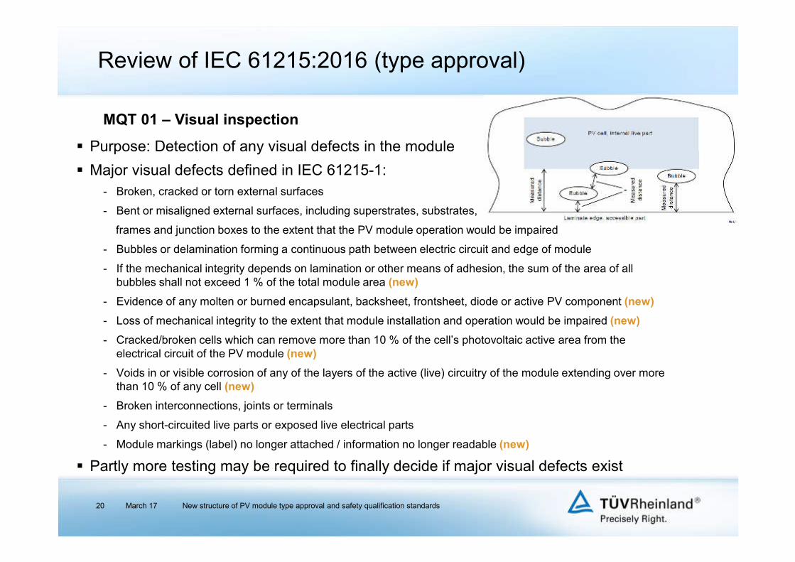
MQT 01 – Visual inspection
Purpose: Detection of any visual defects in the module
Major visual defects defined in IEC 61215-1:- Broken, cracked or torn external surfaces
- Bent or misaligned external surfaces, including superstrates, substrates,
frames and junction boxes to the extent that the PV module operation would be impaired
- Bubbles or delamination forming a continuous path between electric circuit and edge of module
- If the mechanical integrity depends on lamination or other means of adhesion, the sum of the area of all bubbles shall not exceed 1 % of the total module area (new)
- Evidence of any molten or burned encapsulant, backsheet, frontsheet, diode or active PV component (new)
- Loss of mechanical integrity to the extent that module installation and operation would be impaired (new)
- Cracked/broken cells which can remove more than 10 % of the cell’s photovoltaic active area from the electrical circuit of the PV module (new)
- Voids in or visible corrosion of any of the layers of the active (live) circuitry of the module extending over more than 10 % of any cell (new)
- Broken interconnections, joints or terminals
- Any short-circuited live parts or exposed live electrical parts
- Module markings (label) no longer attached / information no longer readable (new)
Partly more testing may be required to finally decide if major visual defects exist

Review of IEC 61215:2016 (type approval)
Minor changes (specifications for test equipment)
Purpose: Determination of maximum output power of modules after stabilization and before and after environmental stress tests.
For power loss determination, reproducibility has to be considered.
Requirements for simulator and for performance measurements slightly changed
March 17 New structure of PV module type approval and safety qualification standards21
MQT 02 – Maximum power determination

Review of IEC 61215:2016 (type approval)
No changes compared to previous standards
Purpose: To determine if module is sufficiently insulated between live parts and accessible parts
- Vtest = 2 x VMaxSys + 1000 VDC (1 min) no dielectric breakdown
- Vtest = VMaxSys (2 min) Riso x module area > 40 MΩ*m²
March 17 New structure of PV module type approval and safety qualification standards22
MQT 03 – Insulation test

Review of IEC 61215:2016 (type approval)
Minor changes (specifications for test equipment and performance)
Reference for measurement: IEC 60891:2009
Array of temperature sensors precisely defined (4 positions, behind cells)
Extrapolation to G = 1000 W/m² within linearity region permitted (1000 W/m² ± 30 %)
Complete IV-curve to be measured
Calculated coefficients only apply to spectrum during measurement
March 17 New structure of PV module type approval and safety qualification standards23
MQT 04 – Temperature coefficients
Module temperaturemeasurement positions

Review of IEC 61215:2016 (type approval)
Major changes
NMOT: similar to former NOCT except that it is measured with module under maximum power rather than in open-circuit
Under maximum power conditions electric energy is withdrawn from the module, therefore less thermal energy dissipates throughout the module than under open-circuit conditions typically NMOT < NOCT
NMOT is determined at Tamb = 20 °C, irradiance G = 800 W/m², wind speed v = 1 m/s
Tilt angle: 37° (± 5°)
Average of four temperature sensors taken
Measurement over at least 10 days
Can be performed simultaneously with Outdoor exposure test (MQT 08)
New value information for data sheets – P@NMOT
March 17 New structure of PV module type approval and safety qualification standards24
MQT 05 – Measurement of nominal module operating temperature (NMOT)

Review of IEC 61215:2016 (type approval)
P(STC): 1000 W/m², 25 °C and AM1.5
Requirements for simulator and for performance measurements slightly changed
Requirements for nominal power (Gate #1) and maximum allowed degradation (Gate #2)
March 17 New structure of PV module type approval and safety qualification standards25
MQT 06.1 – Performance at STC
Gate #1
∗ 1 %
100 ∗ 1
%
100Criterion 1: Pmax above the type label incl. tolerance for each module
∗ 1 %
100
Criterion 2: arithmetic average above the type label incl. tolerance
∗ 1 %
100 ∗ 1
%
100Criterion 3: Voc below the type label incl. tolerance for each module
∗ 1 %
100 ∗ 1
%
100Criterion 4: Isc below the type label incl. tolerance for each module
Gate #2
, ! 0.95 ∗ , ! ∗ 1 % %
100Control measurement: Degradation below 5%
,,: measurement uncertainty of test lab; : manufacturer’s rated lower production tolerance;,: manufacturer’s rated upper production tolerance; r: reproducibility of measurements
Review of IEC 61215:2016 (type approval)
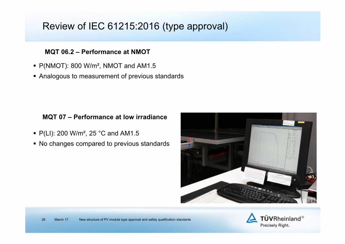
P(NMOT): 800 W/m², NMOT and AM1.5
Analogous to measurement of previous standards
March 17 New structure of PV module type approval and safety qualification standards26
MQT 06.2 – Performance at NMOT
MQT 07 – Performance at low irradiance
P(LI): 200 W/m², 25 °C and AM1.5
No changes compared to previous standards

Review of IEC 61215:2016 (type approval)
Minor changes
Purpose: Assessment of module ability to operate in outdoor conditions
Module subjected to irradiation totaling at least 60 kWh/m²
Module shall operate near maximum power point (use of resistive load or electronic power point tracker)
Outdoor exposure and NMOT determination may be performed simultaneously on the same module
Control measurements:
- MQT 01 (Visual inspection)
- MQT 15 (Wet leakage current test)
March 17 New structure of PV module type approval and safety qualification standards27
MQT 08 – Outdoor exposure test

Review of IEC 61215:2016 (type approval)
Minor changes
Purpose: To determine module ability to withstand hot-spot heating effects
Classification of cell interconnection: case S (serial), case PS (parallel-serial), case SP (serial-parallel)
Selection of four test cells (lowest shunt resistance cell at module edge, (in addition) two lowest shunt resistance cells, highest shunt resistance cell)
Determination of worst-case shading
Maintenance of worst-case shading condition for 1h for each selected cell. If temperature of shadowed cell is still increasing after 1h: total exposure time 5h.
Control measurements:
- MQT 01 (Visual inspection)
- MQT 02 (Max. power det.) (functional control)
- MQT 03 (Insulation test)
- MQT 15 (Wet leakage current test)
March 17 New structure of PV module type approval and safety qualification standards28
MQT 09 – Hot-spot endurance test (wafer-based technologies)
0
0.5
1
1.5
2
2.5
3
3.5
Mo
du
le c
urr
en
t in
Am
ps
0 5 10 15 20 25
Module voltage in Volts
Cell with highestleakage current
Bypass diodeturns on
Module characteristics
with one cell totally shaded
Current-voltage characteristic
of the non-shaded module

Review of IEC 61215:2016 (type approval)
Minor changes
Classification of cell interconnection: case S (serial), case PS (parallel-serial), case SP (serial-parallel)
Determination of worst-case shading of cell (block), procedure depending on cell interconnection
Maintenance of worst case shading condition for 1h
CdTe / CIGS: time between Outdoor exposure test and Hot-spot endurance test < 2-3 d; storage at ≤ 25 ºC (in darkness)
Control measurements:
- MQT 01 (Visual inspection)
- MQT 02 (Max. power det.)
(functional control)
- MQT 03 (Insulation test)
- MQT 15 (Wet leakage current test)
March 17 New structure of PV module type approval and safety qualification standards29
MQT 09 – Hot-spot endurance test (monolithically integrated technologies)
1.0
0.5
0.0
Cu
rre
nt
[A]
160140120100806040200Voltage[V]
0 Cells
2 Cells
4 Cells
6 Cells
10 Cells
16 Cells
30 Cells

Review of IEC 61215:2016 (type approval)
Minor changes
Purpose: Preconditioning of modules with ultra-violet radiation in order to identify materials being susceptible to UV degradation
Module front side to be exposed
Module operation mode changed:
- under load (MPP), if light source with significant fraction in visual region (> 20 % contribution to Pmpp,STC)
- at short-circuit, if light source with negligible fraction
in visual region (investigations prove, that most
technologies match this item)
Control measurements:
- MQT 01 (Visual inspection)
- MQT 15 (Wet leakage current test)
More severe test included in IEC 61730 (Sequence B)
March 17 New structure of PV module type approval and safety qualification standards30
MQT 10 – UV preconditioning test
Review of IEC 61215:2016 (type approval)
March 17 New structure of PV module type approval and safety qualification standards31
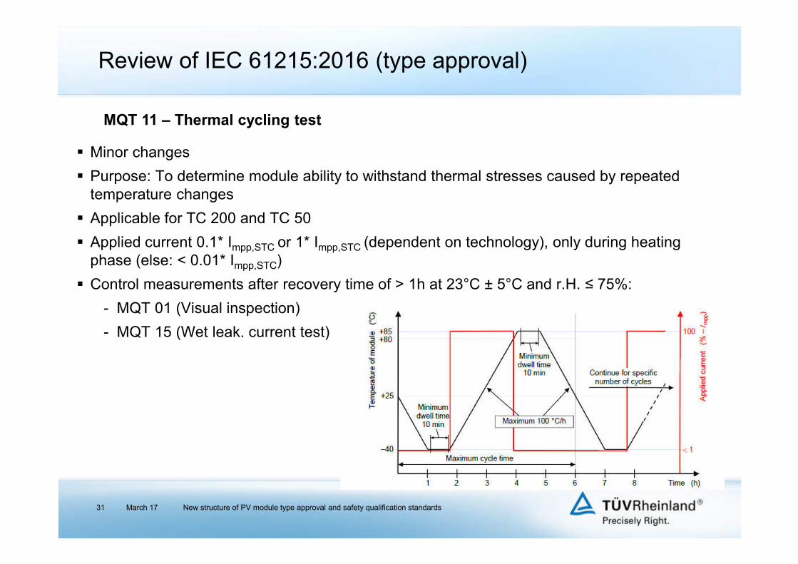
Minor changes
Purpose: To determine module ability to withstand thermal stresses caused by repeated temperature changes
Applicable for TC 200 and TC 50
Applied current 0.1* Impp,STC or 1* Impp,STC (dependent on technology), only during heating phase (else: < 0.01* Impp,STC)
Control measurements after recovery time of > 1h at 23°C ± 5°C and r.H. ≤ 75%:
- MQT 01 (Visual inspection)
- MQT 15 (Wet leak. current test)
MQT 11 – Thermal cycling test

Review of IEC 61215:2016 (type approval)
March 17 New structure of PV module type approval and safety qualification standards32
No changes
Purpose: Investigation of module ability to withstand high temperature and humidity followed by sub-zero temperatures
Control measurements after recovery time of 2-4 h at 23 ± 5°C and r.H. ≤ 75 %:
- MQT 01 (Visual inspection)
- MQT 15 (Wet leakage current test)
MQT 12 – Humidity freeze test

Review of IEC 61215:2016 (type approval)
March 17 New structure of PV module type approval and safety qualification standards33
Minor changes
Purpose: To determine the module ability to withstand long-term penetration of humidity
No preconditioning at room temperature required
Test duration 1000 h -0/+48 h
Control measurements after recovery time of 2-4 h at 23 ± 5°C and r.H. ≤ 75%:
- MQT 01 (Visual inspection)
- MQT 15 (Wet leakage current test)
MQT 13 – Damp heat test

Review of IEC 61215:2016 (type approval)
March 17 New structure of PV module type approval and safety qualification standards34
MQT 14 – Robustness of terminations
Major changes
Purpose: To verify that terminations, its attachment and the cable attachment can withstand stresses caused by assembly or handling operations
MQT 14.1 – Retention of junction box on mounting surface
2-4 h after Humidity freeze test
Force of 40N applied for 10s in the module plane
(four directions in steps of 90°) and perpendicular to junction box
Control measurements: MQT 01 (Visual inspection),
MQT 15 (Wet leakage current test)
MQT 14.2 – Test of cord anchorage
a) Cable pull test: 50x pulling load for 1s, force depending on cable diameterb) Cable torque test: torque on cable for 1min, torque depending on cable diameter
Control measurements: MQT 01 (Visual insp.), MQT 03 (Insulation test), MQT 15 (Wet leakage current test)
Test not necessary if junction box certified acc. to IEC 62790

Review of IEC 61215:2016 (type approval)
March 17 New structure of PV module type approval and safety qualification standards35
MQT 15 – Wet leakage current test
Mostly as in previous standards
Purpose: Investigation of module insulation under wet operating conditions
Connectors are sprayed wet
Different polarity measurement possible
Temperature range: 22 °C ± 2°C

Review of IEC 61215:2016 (type approval)
March 17 New structure of PV module type approval and safety qualification standards36
Minor changes
Purpose: To determine the module ability to withstand a minimum static load
Design load and safety factor (γm) needs to be declared by customer:
- Minimum for design load ≥ 1,600 Pa (individually for positive (downward) and negative (upward) loads)
- Minimum for safety factor γm ≥ 1.5
- Minimum pressure 2,400 Pa
Each mounting method needs to be considered or covered by worst-case testing.
Design load and mounting method with maximum load need to be documented in the installation manual.
Control measurements:
- MQT 01 (Visual inspection)
- MQT 15 (Wet leakage current test)
Test load = γm x Design load
MQT 16 – Static mechanical load test

Review of IEC 61215:2016 (type approval)
March 17 New structure of PV module type approval and safety qualification standards37
Minor changes
Purpose: To verify the module ability to withstand the impact of hail
No changes for 25 mm ice balls
Ice ball diameter according to table
Minimum of 10 shots to specific points
Control measurements:
MQT 01 (Visual inspection),
MQT 15 (Wet leakage current test)
Diameter [mm]
Mass [g]
Test velocity [m/s]
25 7.53 23.0
35 20.7 27.2
45 43.9 30.7
55 80.2 33.9
65 132.0 36.7
75 203.0 39.5
MQT 17 – Hail test
Review of IEC 61215:2016 (type approval)
Major changes
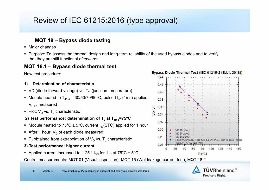
Purpose: To assess the thermal design and long-term reliability of the used bypass diodes and to verify that they are still functional afterwards
MQT 18.1 – Bypass diode thermal test
New test procedure:
1) Determination of characteristic
VD (diode forward voltage) vs. TJ (junction temperature)
Module heated to TJ1-4 = 30/50/70/90°C, pulsed Isc (1ms) applied,
VD1-4 measured
Plot: VD vs. TJ characteristic
2) Test performance: determination of TJ at Tamb=75°C
Module heated to 75°C ± 5°C, current Isc(STC) applied for 1 hour
After 1 hour: VD of each diode measured
TJ obtained from extrapolation of VD vs. TJ characteristic
3) Test performance: higher current
Applied current increased to 1.25 * ISC for 1 h at 75°C ± 5°C
Control measurements: MQT 01 (Visual inspection), MQT 15 (Wet leakage current test), MQT 18.2
March 17 New structure of PV module type approval and safety qualification standards38
MQT 18 – Bypass diode testing

Review of IEC 61215:2016 (type approval)
MQT 18.2 – Bypass diode functionality test
Functionality test after MQT 09 (Hot-spot endurance test) and MQT 18.1 (Bypass diode thermal test)
Method A (dark current):
PV module covered; current applied in sweep from 0 – 1.25 * Isc through solar cells in reverse direction and through the diode in forward direction.
Requirement: measured diode forward voltage
VFM = (N x VFMrated) ± 10 %
(N = number of bypass diodes, VFMrated = diode forward voltage at 25°C (data sheet))
Method B (flash light simulator):
IV-curve measurement by covering each string
Diode is working properly, if PV module has approx. 2/3 performance when 1 diode protects 1/3 of the PV module.
March 17 New structure of PV module type approval and safety qualification standards39
MQT 18 – Bypass diode testing

Review of IEC 61215:2016 (type approval)
New requirement for c-Si (former preconditioning); corresponds to former light-soaking for thin-film
Applied irradiance:
Calculation of stability:
v
March 17 New structure of PV module type approval and safety qualification standards40
MQT 19 – Stabilization
(Pmax - Pmin) / Paverage < x
CellMin. irradiance
initial stabilizationMin. irradiance
final stabilizationRequirement for x
(specified in IEC 61215-1-NN)
c-Si 2 * 5 kWh/m² - 0.01
CdTe 2 * 20 kWh/m² 2 * 20 kWh/m² 0.02
a-Si 2 * 43 kWh/m² 2 * 43 kWh/m² 0.02
CIGS 2 * 10 kWh/m² 2 * 10 kWh/m² 0.02

Basic understanding of the recent modifications of the IEC guidelines for PV modules
Review of IEC 61215:2016 (type approval) - general requirements and test methods
Review of IEC 61730-1:2016 (safety qualification) - requirements for construction
Review of IEC 61730-2:2016 (safety qualification) - requirements for testing
Transitional periods
Closing remarks
Content
March 17 New structure of PV module type approval and safety qualification standards41

Review of IEC 61730:2016 (safety qualification)
March 17 New structure of PV module type approval and safety qualification standards42
IEC 61730-1 Ed. 1 Requirements for construction
IEC 61730-2 Ed. 1Requirements for testing
New IEC 61730Previous status
IEC 61730-1 Ed. 2Requirements for construction
IEC 61730-2 Ed. 2Requirements for testing

Review of IEC 61730-1:2016 (safety qualification)
March 17 New structure of PV module type approval and safety qualification standards43

Review of IEC 61730-1:2016 (safety qualification)Definitions
March 1744
Classification according to IEC 61140Class
(IEC 61140)Application class
(IEC 61730-1:2004)Description
0 B Application in restricted access area
I Special installation measures required Special installation measures required
II A Application in non-restricted access area
III C Basic protection by limitation of voltage (ELV)
influences permitted clearance and creepage distances (table 3 or 4)
marking:
required insulation:
PV module Classification Marking Symbol
Class IIMarking according to IEC 60417-5172:
Class II equipment
Class 0 No marking no symbol
Class IIIMarking according to IEC 60417-5180:
Class III equipment
Protection Class (IEC 61140)
Protection required against
direct contact
Insulation betw. live parts and
accessible metal parts
Insulation betw. live parts and
accessible surfaces
Insulation between live parts of different
potential of the same circuit
Class 0 (B) Yes B B B
Class II (A) Yes R R B
Class III (C) No F F F
F: functional insulation
B: basic insulation
R: reinforced insulation or double insulation
New structure of PV module type approval and safety qualification standards

Review of IEC 61730-1:2016 (safety qualification)Definitions
March 17 New structure of PV module type approval and safety qualification standards45
Insulation coordination
Pollution degree (PD)Description (strongly dependent on module design
and position in module)
1No pollution or only dry, non-conductive pollution occurs, or additional requirements (IEC 61730-2, test sequence B1) are met.
2Only non-conductive pollution occurs except that occasionally a temporary conductivity caused by condensation is to be expected.
3Conductive pollution or dry non-conductive pollution occurs which becomes conductive due to condensation which is to be expected.
Material groups (MG)Description (dependent on used material with the least tendency
to form a creepage path)
I CTI > 600
II 400 ≤ CTI < 600
IIIa 175 ≤ CTI < 400
IIIb 100 ≤ CTI < 175
influences permitted clearance and creepage distances
CTI = comparative tracking index acc. to IEC 60112
influences permitted clearance and creepage distances

Review of IEC 61730-1:2016 (safety qualification)Requirements
March 17 New structure of PV module type approval and safety qualification standards46
The intended use, e.g., O
Vinfluences
permitted clearance and creepage distances and distance through insulation
individual test conditions: test voltage (MST 14, MST 16, MST 17), test temperature (MST 37, MST 56), requirements for installation (MST 21, MST 24)
as defined by the maximum system voltage
for open-rack configurations only
as BAPV – building attached PV
as BIPV – building integrated PV
in heavy snow condition areas ( operating altitude)
in increased temperature condition areas
in marine applications
in vehicle applications
in agriculture applications
etc.
Vnecessitates additional qualification standards (IEC 61701, IEC 62716, V)

Review of IEC 61730-1:2016 (safety qualification)Requirements
March 17 New structure of PV module type approval and safety qualification standards47
Requirements for design and construction
Marking and documentation:
name / registered trade name / trade mark of manufacturer
module type designation
serial number
date and place of manufacture (alternatively: serial number assuring according traceability)
polarity of terminals or leads
maximum system voltage
class of protection against electrical shock
open-circuit voltage with manufacturing tolerances
short-circuit current with manufacturing tolerances
maximum output power with manufacturing tolerances
maximum overcurrent protection rating
all electrical data to be shown relative to STC
international symbols to be used
new

Review of IEC 61730-1:2016 (safety qualification)Requirements
March 17 New structure of PV module type approval and safety qualification standards48
Requirements for design and construction
Marking and documentation: Symbols for equipotential bonding (Fig. 1 or Fig. 2)
Symbol for functional earthing (Fig. 3)
Documentation:
- electrical and mechanical installation:
- recommended maximum series / parallel PV module configurations
- overcurrent protection rating
- electrical ratings of the PV module:
- as above (type label); in addition temperature coefficients (for Voc, Isc and Pmpp)
- class and specific limitations
- environmental conditions (min.: -40°C to +40°C, wind/snow load with safety factor)
- appropriate documentation for safe installation, use and maintenance
- advice not to expose PV modules to concentrated sunlight
- statement for increased output:
“Under normal conditions, a photovoltaic module is likely to experience conditions that produce higher current and/or voltage than reported at standard test conditions. Accordingly, the values of Isc and Voc marked on this PV module should be multiplied by a factor of 1.25 when determining component voltage ratings, conductor current ratings, and size of controls (e.g. inverter) connected to the PV output."

Review of IEC 61730-1:2016 (safety qualification)Requirements
March 17 New structure of PV module type approval and safety qualification standards49
Requirements for design and construction
Electrical components: Junction boxes IEC 62790
Cables EN 50618 (IEC 62930 under development)
Connector IEC 62852 „Do not disconnect under load“
Electrical insulation layers (backsheet, frontsheet):
- classification to Material group (CTI)
- fulfilment of requirements for insulation in thin layers
- appropriate TI, RTE, (RTI) values
Materials: Polymeric materials appropriate TI, RTE, (RTI) values
- flammability class minimum V-1 according to IEC 60695-11-10 (not applicable to insulation in thin layers covered only by MST 24)
- Ball pressure test according to IEC 60695-10-2 at 75°C (not applicable to insulation in thin layers)
- Ignitability test (MST 24) in final application (laminated or PV module)
- Peel test for proof of cemented joints (MST 35)
- Materials creep test (MST 37)

Review of IEC 61730-1:2016 (safety qualification)Requirements
March 17 New structure of PV module type approval and safety qualification standards50
Protection against electrical shock
Clearances (cl) and creepage distances (cr): Refer to table 3/4
Distance through insulation (dti): Cemented joints
- test voltage (MST 16, MST 17): increased by factor 1.35
- Peel test (MST3 5) or Lap shear strength test (MST 36) required
Thin layers (single or multi layer) – “back sheet”
- Single layer
- thickness according to table 3/4 line 1b)
- appropriate TI, RTE, (RTI) values
- dielectric strength for reinforced insulation
- Multi layer
- sum of thicknesses according to table 3/4 line 1b)
- appropriate TI, RTE, (RTI) value for each layer
- dielectric strength for reinforced insulation of the entire multi layer sheet

Backsheet
Encapsulation
Possible solder peakFrontsheet
Internal wiring / live parts
Solar cell
Distance through insulator
(dti)
Assessed distance
through insulator (dti)
Real creepage (cr) path
Assessed creepage (cr) path
Review of IEC 61730-1:2016 (safety qualification)Creepage and clearance distances
March 17 New structure of PV module type approval and safety qualification standards5151
<X mm <X mm
Clearance path
Creepage path
≥X mm ≥X mm

Review of IEC 61730-1:2016 (safety qualification)Creepage and clearance distances
March 17 New structure of PV module type approval and safety qualification standards5252

Review of IEC 61730-1:2016 (safety qualification)Cemented joints
March 17 New structure of PV module type approval and safety qualification standards5353
Encapsulation
Solar cell
Internal wiringGlass
assessed distance through an insulator (dti)
distance through a cemented joint
cemented joint
Insulation materials joint together by adhesion can be assessed as a sole insulator if the joint is durable and can be classified as a “cemented joint”.
A cemented joint can reduce minimum required edge distances.
Requirements for cemented joints: a) no cracks or voids after any test b) 1.35 times higher test voltage in all tests c) volume resistivity >50x106 Ωcm (dry) / >10x106 Ωcm (wet) d) Lap shear test / Peel test

Example: System voltage = 1000 V Edition 1 Edition 2 where to be found in Edition 2
Application Class / Class Class A II Table 1
Thickness of an insulator (e.g. backsheet)
Not defined,limited by partial discharge
test150 µm
Table 3 and 4,1b) thickness of thin layers
Clearance distance8.4 mm
(Table 4 in Edition 1)
14.0 mmTable 3 and 4,
1a) conductive parts and outer surfaces
Creepage distanceNot defined and
interpreted differently
6.4 mm for PD=110.0 mm for PD=2
and MG=I
Table 3 and 4,1a) conductive parts and
accessible surfaces
Review of IEC 61730-1:2016 (safety qualification)Comparison with previous standard
March 17 New structure of PV module type approval and safety qualification standards54

Review of IEC 61730-1:2016 (safety qualification)
March 17 New structure of PV module type approval and safety qualification standards55

Basic understanding of the recent modifications of the IEC guidelines for PV modules
Review of IEC 61215:2016 (type approval) - general requirements and test methods
Review of IEC 61730-1:2016 (safety qualification) - requirements for construction
Review of IEC 61730-2:2016 (safety qualification) - requirements for testing
Transitional periods
Closing remarks
Content
March 17 New structure of PV module type approval and safety qualification standards56

Review of IEC 61730-2:2016 (safety qualification)
March 17 New structure of PV module type approval and safety qualification standards57
Combined test chartMaterials creep
test MST37
UV test (60 kWh/m²)
MQT10 / MST54
MQT01 MQT15
Damp heat test (200 h)
MQT13 / MST53
MQT01 MQT15
UV test(60 kWh/m²)
MQT10 / MST54
MQT01 MQT15
Humidity freeze test (10 cycles)
MQT12 / MST52
MQT01 MQT15
Humidity freeze test (10 cycles)
MQT12 / MST52
1 PV module(unframed if Peel test is required)1 PV module
MST01
Continuity test of equipotential bonding
MST13
Accessibility test
MST11
Sequence A Sequence B
Cold conditioning MST55
MQT01 MQT15
Cold conditioning MST55
MST01 MST16
Dry heat conditioningMST56
MST01 MST16
Humidity freeze test (10 cycles)
MQT12 / MST52
MQT01 MQT15
Humidity freeze test (10 cycles)
MQT12 / MST52
Sequence B1Pollution Degree 1 testing
1 PV module
MQT01 MQT15 MQT01 MQT15
MST16MST17
MST16 MST16
New sequences
New tests
Extended requirements of individual tests and combination of tests in a sequence
Adapted or new test methods

Review of IEC 61730-2:2016 (safety qualification)
March 17 New structure of PV module type approval and safety qualification standards58
Minor or major changes in test procedures
Fire testMST23
Module breakage test
MST32
1 PV moduleNo. of PV modulesdepend on national
requirements
Ignitability test MST24
1 PV module
Peel testMST35
1 unframed PV module Sequence B
Lap shear strength testMST36
10 samples 10 samples
20 samples
Lap shear strength testMST36
New tests

Review of IEC 61730-2:2016
March 17 New structure of PV module type approval and safety qualification standards59
Minor or major changes in test procedures
1 PV module
Bypass diode thermal test
MST18 / MQT25
MQT01 MQT18.2MQT15
Hot-spot endurance test MQT09 / MST22
MQT01 MQT1502
Reverse current overload test
MST26
MST01
Temperature testMST21
Sequence F
1 unframed PV module
Impulse voltagetest
MST14
MST16
Sequence G
MST01 MST17MST16
Measurement of NMOT &Outdoor Exposure Test
MQT05 & MQT08
MQT01 MQT15
MQT19.2Final Stabilization
MQT06.1
MQT03MQT02
MST01
Adapted or new test methods
Max. power determination
MQT02 / MST02
Visual inspectionMQT01 / MST01 incl. MST05 and MST06
Screw connections test
MST33
Insulation thickness test MST04
only sample from Sequence B
Bypass diode functionality test
MQT18.2 / MST07
Includes MST 05 (Durability of markings) and MST 06 (Sharp edge test)

Purpose: Detection of any visual defects and changes in the module
As MQT 01 of IEC 61215-2, but with additional major visual defects defined:
- in cemented joints bubbles or delaminations with closest distances to each other ≤ 2 times the minimum required distance through cemented joint
evaluated as conductive and electrically connected
- markings not complying with demands on contents and with Durability of markings test
- edges not complying with Sharp edge test
March 17 New structure of PV module type approval and safety qualification standards60
Review of IEC 61730-2:2016 (safety qualification)
MST 01 – Visual inspection

Review of IEC 61730-2:2016 (safety qualification)
New requirement
Purpose: Determination of layer thicknesses in order to verify the minimum insulation thickness for thin layers acc. to table 3+4, IEC 61730-1
Only applicable for polymeric insulation layers
Performed after environmental test sequence B
Three samples per module side chosen for measurement (to be representative for min. insulation thickness, e.g., soldering joints, edge of laminate V)
Requirement: minimum insulation thickness acc. to table 3+4, IEC 61730-1
March 17 New structure of PV module type approval and safety qualification standards61
MST 04 – Insulation thickness test

Review of IEC 61730-2:2016 (safety qualification)
March 17 New structure of PV module type approval and safety qualification standards62
New requirement
Purpose: Label shall be durable and legible also after stress and climate chamber testing
Marking rubbed after pre-conditioning for 15 s by hand using
- Cloth soaked with water
- Cloth soaked with petroleum spirits
Control testing on one test sample from each
sequence
MST 05 – Durability of markings

Review of IEC 61730-2:2016 (safety qualification)
New requirement (equivalent to ANSI/UL 1703 sharp edge test)
Purpose: Accessible module surface shall be smooth and free from sharp edges, burrs, etc. which may damage the insulation of conductors or pose a risk of injury
Compliance checked with sharp edge tester
March 17 New structure of PV module type approval and safety qualification standards63
MST 06 – Sharp edge test

Review of IEC 61730-2:2016 (safety qualification)
No changes
Purpose: Investigation if adequate protection against accessibility to hazardous live parts (> 35 V)
Apparatus: Cylindrical test fixture and ohmmeter or continuity tester
Pass criteria: At no time during test resistance of less than 1 MΩ between test fixture and PV module live parts
March 17 New structure of PV module type approval and safety qualification standards64
MST 11 – Accessibility test

Review of IEC 61730-2:2016 (safety qualification)
No changes
Purpose: Determination whether any polymeric front / rear surfaces of the module can withstand routine handling during installation and maintenance without causing risk of electric shock.
Not applicable to rigid-to-rigid bonded assemblies (e.g. glass/glass PV modules)
Performed after chamber tests
Test fixture placed on surface for 1 min and then drawn across the surface of the PV module with 150 mm/s ± 30 mm/s. Repeated five times in different directions.
Control measurements:
- MST 01 (Visual inspection)
- MST 16 (Insulation test)
- MST 17 (Wet leakage current test)
March 17 New structure of PV module type approval and safety qualification standards65
KeyA 150 mm from axis to center of weightB 170 mm from axis to test pointC Carbon steel strip 0,64 mm ± 0,05 mm thickD 140° angle between horizontal plane and the strips’ edgeQ Total force exerted at test point 8,9 N ± 0,5 NR Tip rounded with radius 0,115 mm ± 0,025 mmT Steel strip top angle 90°± 2°
Detail d
R
Q
T
A
B
D
Section a-a
d
Section b-b
+++
a a
bb
C
Direction of movement
KeyA 150 mm from axis to center of weightB 170 mm from axis to test pointC Carbon steel strip 0,64 mm ± 0,05 mm thickD 140° angle between horizontal plane and the strips’ edgeQ Total force exerted at test point 8,9 N ± 0,5 NR Tip rounded with radius 0,115 mm ± 0,025 mmT Steel strip top angle 90°± 2°
Detail d
R
Q
T
Detail d
R
Q
T
A
B
D
Section a-a
d
A
B
D
Section a-a
d
Section b-bSection b-b
+++
a a
bb
C
Direction of movement
+++
a aa
bb
C
Direction of movement
MST 12 – Cut susceptibility test

Review of IEC 61730-2:2016 (safety qualification)
Former Ground continuity test, minor changes
Purpose: To demonstrate that there is a conductive path between all exposed conductive surfaces of the PV module, so that the exposed conductive surfaces can be adequately grounded in a PV system
Test conditions:
- current of 2.5 * maximum overcurrent protection rating (± 10 %) applied
- time: 2 min
All other frame parts tested
March 17 New structure of PV module type approval and safety qualification standards66
MST 13 – Continuity test of equipotential bonding

Review of IEC 61730-2:2016 (safety qualification)
Major changes
Purpose: To verify capability of module insulation to withstand atmospheric over-voltages
Test performed with unframed PV module. If frame integral part of the edge insulation, framed module is acceptable.
No preconditioning (TC 200)
Test voltage according to table B.1:
Control measurements:
- MST 01 (Visual inspection), MST 16 (Insulation test)
March 17 New structure of PV module type approval and safety qualification standards67
MST 14 – Impulse voltage test

Review of IEC 61730-2:2016 (safety qualification)
As MQT 03 with increased test voltage:
- Vtest = 4 x VMaxSys + 2000 VDC
Test voltage depending on Class
New: Higher test voltage for „cemented joints“
- Vtest = (4 x VMaxSys + 2000 VDC) x 1.35
- Maximum possible Vtest = (4 x 1500 VDC + 2000 VDC) x 1.35 = 10800 VDC
March 17 New structure of PV module type approval and safety qualification standards68
MST 16 – Insulation test

Review of IEC 61730-2:2016 (safety qualification)
As MQT 15
New: Higher test voltage for „cemented joints“
- Vtest = VMaxSys x 1.35
- Maximum possible Vtest = 1500 VDC x 1.35 = 2025 VDC
March 17 New structure of PV module type approval and safety qualification standards69
MST 17 – Wet leakage current test

Review of IEC 61730-2:2016 (safety qualification)
Major changes
Purpose: To determine maximum reference temperatures for all module components and materials in order to verify suitability of usage
Indoor and outdoor method are possible; indoor preferred
Material specific values “RTI, RTE or TI” needed; to be provided by manufacturer
Only one test cycle near maximum power point
Sub-structure considered: PV module to be mounted
- above a black platform in acc. with the installation instructions
- directly on a black platform, if no indications
for spacing given by manufacturer
Control measurements:
- MST 01 (Visual inspection)
- MST 16 (Insulation test)
- MST 17 (Wet leakage current test)
March 17 New structure of PV module type approval and safety qualification standards70
MST 21 – Temperature test
38,0°C
163,0°C
40
60
80
100
120
140
160
Review of IEC 61730-2:2016 (safety qualification)
March 17 New structure of PV module type approval and safety qualification standards71
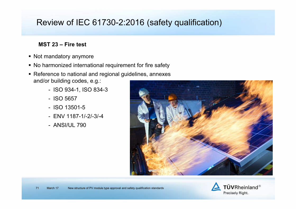
Not mandatory anymore
No harmonized international requirement for fire safety
Reference to national and regional guidelines, annexes and/or building codes, e.g.:
- ISO 934-1, ISO 834-3
- ISO 5657
- ISO 13501-5
- ENV 1187-1/-2/-3/-4
- ANSI/UL 790
MST 23 – Fire test

Review of IEC 61730-2:2016 (safety qualification)
New requirement
Purpose: Evaluation of ignitability of outer module layers
Based on ISO 11925-2 (if acc. approval can be shown, test can be omitted)
- one module per type family selected (without pre-stress)
- test conditions: 23°C ± 5°C, 50 % ± 20 %, defined max. air speed 5 cm from the surface (pre-conditioning: 48 h at 23°C / 50 %)
- gas burner with specific mounting and mobility applied to defined module positions (each for 15 s)
- Polymerics applied for this test; electrical components
(junction box etc.), glass, metal not to be tested
- pass/fail criterions: ignitability, maximum flame height, length of destroyed area
March 17 New structure of PV module type approval and safety qualification standards72
MST 24 – Ignitability test

Review of IEC 61730-2:2016 (safety qualification)
Minor changes (specifications for test equipment)
Purpose: To determine the risk of ignition or fire under reverse current fault conditions
A reverse current can be applied also for warming up the modules in alpine region
Test conditions:
- current of 1.35 x maximum overcurrent protection rating applied
- time: 2 h
Control measurements:
MST 01 (Visual inspection), MST 16 (Insulation test), MST 17 (Wet leakage current test)
March 17 New structure of PV module type approval and safety qualification standards73
MST 26 – Reverse current test

Review of IEC 61730-2:2016 (safety qualification)
March 17 New structure of PV module type approval and safety qualification standards74
Minor changes
Purpose: To verify that the risk of physical injuries
can be minimized in case module is broken in installation
Test procedure reduced to only one impact from one height:
300 mm (450 mm and 1220 mm impacts not applied anymore)
Minor modification of pass criteria:
1. No separation from mounting structure or frame
and
2. either
a) no breakage occurs
or
b) breakage occurs, but no shear or opening larger than 76 mm diameter develops and no particles larger than 65 cm² ejected from test sample
Control measurements:
MST 01 (Visual inspection), MST 13 (Continuity test of equipotential bonding)
MST 32 – Module breakage test

Review of IEC 61730-2:2016 (safety qualification)
New requirement
Purpose: To verify long-life cycle of screws and nuts used in a module
Components like screws and nuts transmitting contact pressure or likely to be tightened by the user are to be tightened and loosened five times. Screws and nuts of insulating material are to be removed completely during each screws loosening operation.
Pass criteria:
- No damage impairing the further use of the fixing or screwed connection
- After the test, it shall still be possible to use the screw or nut made of insulation material in the intended manner.
March 17 New structure of PV module type approval and safety qualification standards75
MST 33 – Screw connections test
Review of IEC 61730-2:2016 (safety qualification)
March 17 New structure of PV module type approval and safety qualification standards76
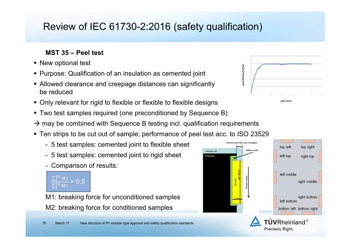
New optional test
Purpose: Qualification of an insulation as cemented joint
Allowed clearance and creepage distances can significantly be reduced
Only relevant for rigid to flexible or flexible to flexible designs
Two test samples required (one preconditioned by Sequence B)
may be combined with Sequence B testing incl. qualification requirements
Ten strips to be cut out of sample; performance of peel test acc. to ISO 23529
- 5 test samples: cemented joint to flexible sheet
- 5 test samples: cemented joint to rigid sheet
- Comparison of results:
M1: breaking force for unconditioned samples
M2: breaking force for conditioned samples
MST 35 – Peel test
∑ '()(
∑ ' ()(
> 0.5

Review of IEC 61730-2:2016 (safety qualification)
March 17 New structure of PV module type approval and safety qualification standards77
New optional test
Purpose: Qualification of an insulation as cemented joint
Allowed clearance and creepage distances can significantly be reduced
Only relevant for rigid to rigid designs
20 test samples required acc. to ISO 4587:2003
- 10 test samples go through Sequence B
- 10 test samples without preconditioning
- Measurement of breaking force M during rupture
- Comparison of results:
M1: breaking force for unconditioned samples
M2: breaking force for conditioned samples
MST 36 – Lap shear strength test
∑ '()(
∑ ' ()(
> 0.5

Review of IEC 61730-2:2016 (safety qualification)
New requirement
Purpose: Verification that materials used in module will not show creep or lose adhesion during high operation temperatures in the field (frontsheet-backsheet, backsheet-JB / -back railV)
Not applicable if creep at all interfaces prevented by mechanical mounting means
Modules tested in environmental chamber with worst-case mounting and max. angle
Test conditions: 105°C ± 5°C, dry, for 200 h (for module types for pure open rack configuration: 90°C ± 3°C)
Control measurements:
- MST 01 (Visual inspection)
- MST 11 (Accessibility test)
- MST 13 (Continuity test of equipotential bonding)
- MST 16 (Insulation test)
- MST 17 (Wet leakage current test)
- Check of creepage and clearance distances acc. to table 3 or 4 of IEC 61730-1
March 17 New structure of PV module type approval and safety qualification standards78
MST 37 – Materials creep test

Review of IEC 61730-2:2016 (safety qualification)
March 17 New structure of PV module type approval and safety qualification standards79
New optional test sequence (required for extension to Pollution degree 1)
One module tested
Can be combined with Sequence A
New tests included:
- MST 55 (Cold conditioning)
- MST 56 (Dry heat conditioning)
Sequence B1

Review of IEC 61730-2:2016 (safety qualification)
March 17 New structure of PV module type approval and safety qualification standards80
New climate chamber test
Relevant in Sequence B1 (Pollution degree 1)
Test conditions:
- Temperature: -40°C ± 3°C
- Time: 48 h
Control measurements:
- MST 01 (Visual inspection)
- MST 16 (Insulation test)
MST 55 – Cold conditioning

Review of IEC 61730-2:2016 (safety qualification)
March 17 New structure of PV module type approval and safety qualification standards81
New climate chamber test
Relevant in Sequence B1 (Pollution degree 1) and for MST 37 (Material creep test)
Test conditions:
- Temperature: 105 °C ± 5°C (for module types for pure open rack configuration: 90°C ± 3°C)
- r.H. ≤ 50%
- Time: 200 h
Control measurements
- MST 01 (Visual inspection)
- MST 16 (Insulation test)
MST 56 – Dry heat conditioning
Review of IEC 61730-2:2016 (safety qualification)
March 17 New structure of PV module type approval and safety qualification standards82
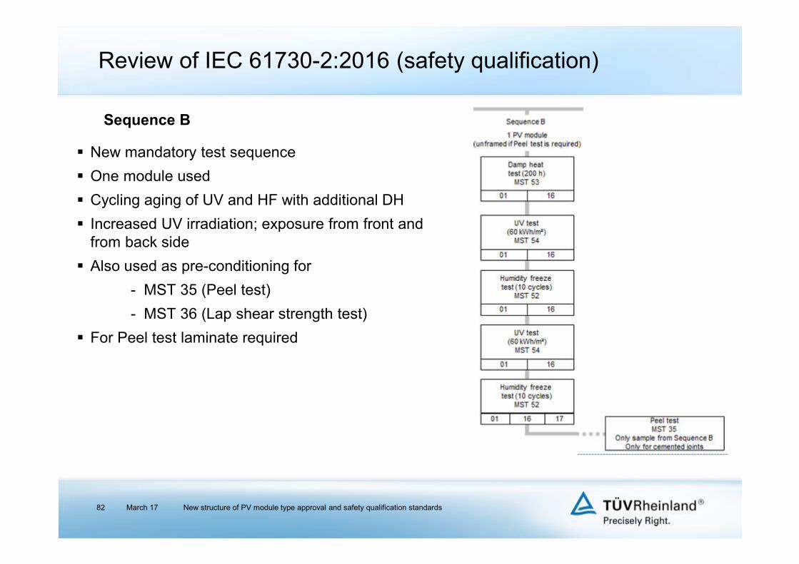
New mandatory test sequence
One module used
Cycling aging of UV and HF with additional DH
Increased UV irradiation; exposure from front and from back side
Also used as pre-conditioning for
- MST 35 (Peel test)
- MST 36 (Lap shear strength test)
For Peel test laminate required
Sequence B

IEC 61215 & 61730:2016 combined testing tree
March 17 New structure of PV module type approval and safety qualification standards83
Qualification of
one design
one power range
15 test samples
duration 4 - 5 months

Basic understanding of the recent modifications of the IEC guidelines for PV modules
Review of IEC 61215:2016 (type approval) - general requirements and test methods
Review of IEC 61730-1:2016 (safety qualification) - requirements for construction
Review of IEC 61730-2:2016 (safety qualification) - requirements for testing
Transitional periods
Closing remarks
Content
March 17 New structure of PV module type approval and safety qualification standards84

Transitional periods
March 17 New structure of PV module type approval and safety qualification standards85
No defined date of withdrawal (DOW) for IEC 61215:2005 and IEC 61646:2008
Also no DOW for IEC 61730:2004, however generally considered not to be acc. to state of the art for PV modules
New EN 61730:20XX will probably appear mid of 2017
No active withdrawal of IEC 61730:2004 certificates, but presumably max. 12 months after publication of new EN 61730
TÜV Rheinland entities agreed that from March 2017 for new basic certification applications the new IEC61215:2016 and IEC61730:2016 will be offered only

Basic understanding of the recent modifications of the IEC guidelines for PV modules
Review of IEC 61215:2016 (type approval) - general requirements and test methods
Review of IEC 61730-1:2016 (safety qualification) - requirements for construction
Review of IEC 61730-2:2016 (safety qualification) - requirements for testing
Transitional periods
Closing remarks
Content
March 17 New structure of PV module type approval and safety qualification standards86

IEC 61215-1, -1-1 and -2 were published in March 2016.
IEC 61215-1-2, 1-3 and 1-4 were published in December 2016.
IEC 61730-1 and -2 were published in August 2016.
EN 61730 publication is expected in the next months without any modifications.
North America has formed a committee for the harmonization of ANSI/UL 1703 and IEC 61730; aim: ANSI 61730.
Retesting in case of design or material changes are regulated in IEC TS 62915 (former IECEE Retesting Guideline).
Pollution Degree 1 testing acc. to IEC 61730-1 sequence B1 may enable reduced edge distances and makes Material Groups irrelevant for these.
Material Group I requires a CTI ≥ 600 from all materials that may form a creepage path surface. Material Group I may allow smaller edge distances even for higher Pollution Degrees.
Cemented joints are a valid solution for any design to reduce edge distances.
Generally, new standards provide a large number of options for manufacturers in order to expose its design on the market, but require detailed design review in advance and pre-information to be supplied for test institute.
March 17 New structure of PV module type approval and safety qualification standards87
Closing remarks

Questions?
March 17 New structure of PV module type approval and safety qualification standards88
For more clarity:
TÜV Rheinland Energy GmbH
Business Field Solar Energy
Solar Energy Assessment Center
Tel: + 49 221 806 ext. 5222E-Mail: [email protected]
Web: www.tuv.com/solarenergySelected reference cases: www.tuv-e3.com/solar