New stainless and speciality steel long products mini...
6
122 S T E E L M A K I N G In March 2002, Baosteel Group, one of the largest steel producers in the PR of China, appointed Danieli for the supply of a new specialty steel mini- mill to Shanghai No.5 Steel Co. Ltd in Baoshan Shanghai province. Following a very tight project schedule of only 19 months, the commissioning stage started on time on 31 October 2003, with the first hot-rolled bar successfully delivered onto the cooling bed. Size tolerance of the first batch of rolled bars was already up to Chinese standard and subsequent lots reached or exceeded the contractual guarantees. Meltshop general overview The meltshop, designed for a capacity of approximately 380kt/yr of liquid steel, comprises: ■ Scrap yard ■ 60t AC EAF featuring 60MVA transformer and conductive arms (see Figure 1) ■ 60t LF provided with a 13.2MVA transformer and inert roof system ■ 60/55t double tank VD/VOD station ■ 60/55t AOD station (in consortium with Praxair) ■ 3 -strand 160 x 160mm billet caster equipped with hydraulic mould oscillator and mould and final electromagnetic stirring (EMS) There are three independent material handling systems for the EAF, LF and AOD/VOD units, thus granting high plant operation flexibility. Two main de-dusting and filtering plants are provided for the EAF/LF and AOD converter, while the VOD unit is served by its own, under-vacuum filtering plant. Process routes and main technological highlights Different process routes are selected in relation to the specific steel grade to be produced. For non-stainless steels the main route will be EAF – LF – VD – CCM. Vacuum degassing will not be applied to the less demanding steels. For stainless steels two main routes are foreseen: ■ 1st route: EAF – AOD – LF – CCM, for most of the grades ■ 2nd route: EAF – AOD – VOD – (LF) – CCM, for very low carbon and/or nitrogen grades EAF Operation is based on two different shells, one with an eccentric bottom tapping (EBT) device for slag-free tapping for non-stainless steels and one provided with a tapping spout for stainless steels, also suitable for slag pouring into the ladle, thus clearing the EAF shell for the next heat. Bottom New stainless and speciality steel long products mini-mill for Baosteel Baosteel Shanghai No.5 new mini-mill has been designed using the most modern and proven technologies presently available for long products production. The plant includes EAF and secondary steelmaking, and billet casting directly linked to the rolling mill via a reheat furnace, produces straight bars and coil. Riccardo Tosini, Francesco Toschi and Giovanni Salvador Danieli ● Figure 1 First heat at Shanghai n°5 EAF
Transcript of New stainless and speciality steel long products mini...

122
S T E E L M A K I N G
In March 2002, Baosteel Group, one of the largeststeel producers in the PR of China, appointedDanieli for the supply of a new specialty steel mini-mill to Shanghai No.5 Steel Co. Ltd in BaoshanShanghai province. Following a very tight projectschedule of only 19 months, the commissioningstage started on time on 31 October 2003, with thefirst hot-rolled bar successfully delivered onto thecooling bed. Size tolerance of the first batch of rolledbars was already up to Chinese standard andsubsequent lots reached or exceeded the contractualguarantees.
Meltshop general overview The meltshop, designed for a capacity ofapproximately 380kt/yr of liquid steel, comprises:
■ Scrap yard■ 60t AC EAF featuring 60MVA transformer and
conductive arms (see Figure 1)■ 60t LF provided with a 13.2MVA transformer and
inert roof system■ 60/55t double tank VD/VOD station ■ 60/55t AOD station (in consortium with Praxair) ■ 3 -strand 160 x 160mm billet caster equipped with
hydraulic mould oscillator and mould and finalelectromagnetic stirring (EMS)
There are three independent material handlingsystems for the EAF, LF and AOD/VOD units, thusgranting high plant operation flexibility. Two mainde-dusting and filtering plants are provided for theEAF/LF and AOD converter, while the VOD unit isserved by its own, under-vacuum filtering plant.
Process routes and main technologicalhighlights Different process routes are selected in relation to thespecific steel grade to be produced.
For non-stainless steels the main route will be EAF –LF – VD – CCM. Vacuum degassing will not beapplied to the less demanding steels.
For stainless steels two main routes are foreseen:
■1st route: EAF – AOD – LF – CCM, for most of theg r a d e s
■2nd route: EAF – AOD – VOD – (LF) – CCM, forvery low carbon and/or nitrogen grades
E A F Operation is based on two different shells, onewith an eccentric bottom tapping (EBT) device fors l a g-free tapping for non-stainless steels and oneprovided with a tapping spout for stainless steels,also suitable for slag pouring into the ladle, thusclearing the EAF shell for the next heat. Bottom
New stainless and speciality steel long
products mini-mill for Baosteel
Baosteel Shanghai No.5 new
mini-mill has been designed using
the most modern and proven
technologies presently available
for long products production. The
plant includes EAF and secondary
steelmaking, and billet casting
directly linked to the rolling mill
via a reheat furnace, produces
straight bars and coil.
Riccardo Tosini, Francesco Toschiand Giovanni SalvadorDanieli
● Figure 1 First heat at Shanghai n°5 EAF

123
S T E E L M A K I N G
stirring is via three porous plugs in the furnacehearth. This intensifies metal/slag mixing andconsequently enhances thermal and chemicalhomogenisation. For stainless steel production, useof oxygen and carbon is not envisaged, althoughunder some circumstances, a limited amount ofoxygen blown through a door lance can be expected.After tapping and before pouring the liquid steel intothe AOD vessel, de-slagging from the transfer ladleis performed at an off-line skimming station.
AOD/VOD The AOD concept is based on reduced carbonmonoxide pressure by dilution of oxygen with argonand nitrogen. Decarburisation is performed either inthree to five steps, or continuously. The temperatureis controlled by adding high carbon FeCr, FeMn,FeNi and scrap, and by limiting metal oxidation. Thetypical AOD process pattern and relevant carboncontent, carbon removal rate and temperatureprofile for AISI 304L are illustrated in Figure 2.
The VOD has dynamic process control, based oncontinuous analysis of the process gas. Gas samplestaken as close as possible to the process source (onthe low-pressure side between vacuum tank and firstejector) are analysed on-line in a massspectrometer, quickly enough to enable the mainprocess parameters (such as carbon content, oxygen
blowing, carbon removal rate, metal oxidation andsteel temperature) to be controlled in real time.
Typical graphs of waste gas analysis duringdecarburisation and relevant oxygen blowingpattern are shown in Figure 3.
● Figure 4 LF Inert roof concept
● Figure 3 AISI 430 - Waste gas analysis during decarburisation andoxygen blowing phase
● Figure 2 AOD blowing pattern- AISI 304L

124
S T E E L M A K I N G
Ladle furnace The LF is equipped with a speciallydesigned inert roof, where a small positive pressuresignificantly reduces outside air flow into the ladle,thus minimising electrode oxidation, steel oxidation,as well as H and N, pick-up in the treated steel,while also preventing any emission of fume to theoutside environment (see Figure 4). Auxiliary equipment All main technological areasare provided with a complete set of auxiliaryequipment for monitoring and operation of the mainunits. This includes inert gas bottom stirring in theladle, automatic and manual temperature/O/N/H/measuring/sampling devices and instrumentation,cored wire and Al wire feeders, and emergencystirring top lance. A second off-line skimming stationd e-slags the ladle between the AOD and the VO Dstation for very low C and/or N stainless grades. Continuous casting machine The 3-strand CCM( s e e Figure 5) is designed for casting a very widerange of steel grades (see Table 1). To cover this widerange, hydraulic mould oscillation and air- m i s tspraying cooling are applied. Hydraulic mouldoscillation makes it possible for stroke and frequencyadjustment during casting so that those parameterswhich affect billet surface and sub-surface qualitysuch as positive/ negative strip time can be optimisedfor each group of steel grades, relevant mouldpowder characteristics and mould EMS parameters. Italso significantly improves surface quality whencompared to conventional electromechanicallydriven oscillation systems.
A i r-mist spray provides high spraying efficiencythanks to the wide range of water flow rates that canbe sprayed with a single nozzle. Also a more uniformheat removal rate from the billet is produced. Toc o u n t e r-balance the tendency of ferritic stainless steelsto bulge, a few rows of containment rollers below themould are provided, although they not necessary forall the other steel grades.
Continuous billet unbending in the withdrawal andstraightening area prevents large strain variationparticularly at the solid/liquid interface, and enhancessound internal quality. The combination of mould andfinal EMS improves carbon centre segregation andcentre porosity in high carbon steels.
Quality results expected on 160mm as-c a s taustenitic stainless steel billet are summarised inTable 2.
Rolling mill Starting material: Billet160 x 160 x 10,000mm, weight 1,950kg120 x 120 x 10,000mm, weight 1,050kg
The 350ktpa mill consists of the following:
Billet reheating A reheating furnace with anominal capacity of 80tph is directly connected to theCCM for billet hot charging purposes. This decreasesenergy consumption, increases billet yield andreduces billet handling cost.
Rolling mill (see Figure 6) This comprises:
■H i g h -speed billet descaling facilities■6 -stand high-speed roughing mill, located at
suitable distance from first intermediate stand for
● Figure 5 3 -strand CCM
● Figure 6 Shanghai n°5 rolling mill in operation
125
S T E E L M A K I N G
f r e e-rolling operation between roughing andintermediate mills, and correct rolling speedselection at stand 1 ingoing side
■1 2 -stand intermediate-prefinishing mill on Starhousingless stands (SHS) arranged in alternate H/Vorientation with quick changing facilities. Aninduction furnace is provided at stand 7 ingoingside, for improving temperature uniformity beforeentering the intermediate mill
■Wa t e r-cooling boxes before and after the RSBfinishing block, to achieve the correct bartemperature for low temperature finishing rolling( LTR) at the RSB block and feeding the downstreamproduction and finishing lines for straight bars, bar-i n -coil and wire rod. LTR enables on-line control ofgrain size and improved properties
■Kocks-Danieli 3-roll RSB fitted with automaticquick changing facilities and based on a wide‘Free-size rolling’ capability (9% of nominal bardiameter). The 4-pass RSB block (see Figure 7)acts as finishing mill for straight bar and bar-in-coil production and as pre-finisher for thesubsequent wire-rod production outlet. It grantshigh operational and market flexibility thanks to itswide Free-size rolling range, LTR and just-in-time
rolling capability. Any size can be rolled by usinga minimum number of roll sets and standchanges, making it possible to roll with just onepass family in the upstream mill
Straight bar production Finishing rolling of thewhole straight bar size range is performed at the RSB
● Figure 9 Similar rotary furnace in operation
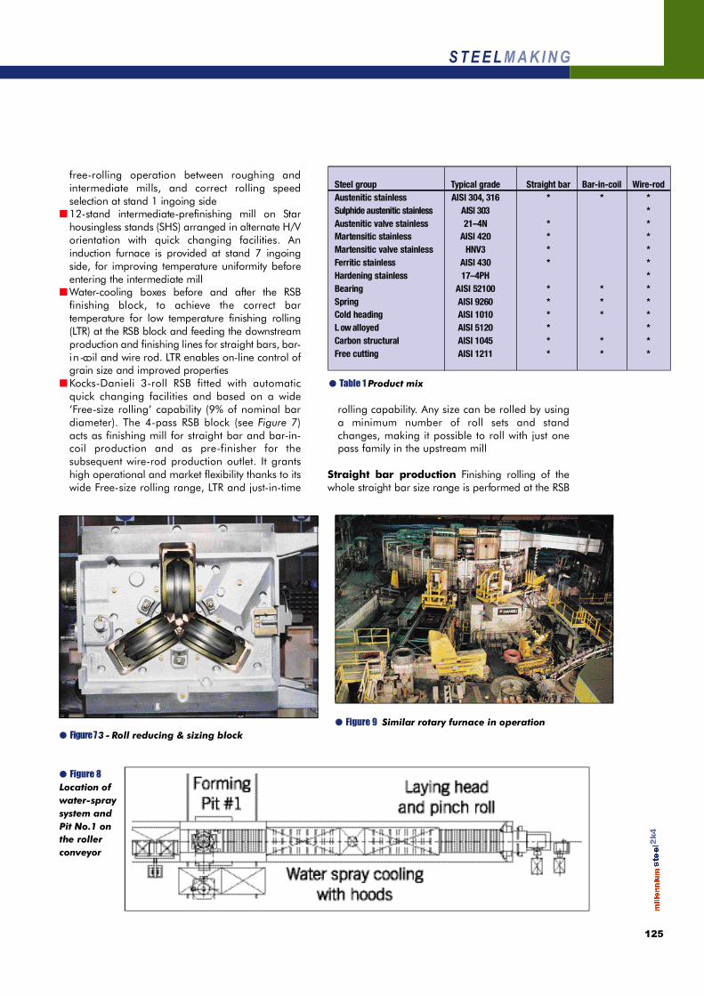
● Figure 8Location ofw a t e r -s p r a ysystem andPit No.1 onthe rollerc o n v e y o r
● Figure 7 3 - Roll reducing & sizing block
● Table 1 Product mix
Steel group Typical grade Straight bar B a r- i n - c o i l W i r e - r o dAustenitic stainless AISI 304, 3 1 6 * * *Sulphide austenitic stainless AISI 303 *Austenitic valve stainless 2 1 – 4 N * *Martensitic stainless AISI 420 * *Martensitic valve stainless H N V 3 * *Ferritic stainless AISI 430 * *Hardening stainless 1 7 – 4 P H *Bearing AISI 52100 * * *Spring AISI 9260 * * *Cold heading AISI 1010 * * *L ow alloyed AISI 5120 * *Carbon structural AISI 1045 * * *Free cutting AISI 1211 * * *

126
S T E E L M A K I N G
block. Rolling temperature is controlled by the waterbox located upstream of the RSB, whilst the bartemperature at the rake-type cooling bed entry iscontrolled by the water boxes after the RSB.
Martensitic stainless and martensitic valve stainlesssteels undergo slow-cooling in cooling boxes at thecooling bed delivery side after the cut- t o- l e n g t hstation. For other steel grades natural air cooling plusdownstream off-line heat treatment is foreseen. Barfinishing facilities comprise automatic counting andb u n d l i n g, and slow-cooling boxes for martensiticstainless steel bars.Wire rod and bar-in-coil production T h i scomprises a controlled-cooling line featuring high-speed laying head, roller conveyor with water-s p r a ysystem, fast and retarded cooling, and double-reforming pit. It is located immediately after the looplayer and is used for stainless steel coil formation anddelivery to the rotary-type annealing furnace. Pit 2,located at the roller conveyor-end, is used for theremaining grades. Additionally, there are two Garretcoilers and associated walking beam coil conveyorwith fast and retarded cooling facilities, a conveyingsystem for hot-coil transfer to the rotary annealingfurnace, and an overhead C-hook conveyor withcompacting/tying facilities, serving both wire rod andb a r- i n -coil production outlets.Wire rod production Here the RSB block acts aspre-finisher for the high-speed finishing block. Theloop layer delivers wire rod loops onto the controlledcooling roller conveyor where several different
treatments can be performed accordingto needs (see Table 3).
To this end the roller conveyor isequipped with a set of specificdevices, namely:
■ Wa t e r-spray system before pitN o . 1■ Coil reforming pit No.1, locatedafter the loop layer (see Figure 8),provides hot-coils for delivery to therotary furnace. It is equipped with apit by-pass when not required■ Set of heat retaining hoods andpowerful fans for slow and fastc o o l i n g■ Coil reforming pit No.2, located atthe end of the roller conveyor, fornormal coil forming operation
The various finishing and treatmentroutes, applicable in wire rodproduction are shown in Table 3B a r - i n -coil production R o u n dbars from the RSB are delivered tothe coilers after water cooling in thewater box to the aim coilingtemperature. Formed coils can bedelivered either directly to thewalking beam conveyor or to the
● Table 2 Quality results expected on 160mm as-cast austeniticstainless steel billet
A s p e c t s Pe r f o r m a n c e Thanks toAustenitic Dendritic columnar crystallisation Mould tapersolidification Edge zone ≥11mm in width P r i m a ry coolings t r u c t u r e comprising fine grain size Powder lubrication
Absence of central porosity Mould and final EMSS e c o n d a ry cooling
p a r a m e t e r s
Homogeneous distribution of delta Chemical analysis balanceferrite Homogeneity of primary and
s e c o n d a ry cooling
Chemical analysis homogeneity Mould and final EMSHomogeneity of cooling
Distance between dentrites arms 0.005 to 0.010mm Mould taper
P r i m a ry coolingPowder lubrication
● Table 3 On-line heat treatments
Route Coil pit Tr e a t m e n t / p r o c e s s Steel gradeA N ° 2 Rapid cooling by water-spray Austenitic stainless
Cooling by fans Sulphide austenitic stainless
B N ° 1 Coil heat-treatment into Austenitic stainless r o t a ry furnace Austenitic valve stainless,
Rapid cooling in water tank martensitic stainless,after furnace martensitic valve stainless
C N ° 1 Rapid cooling by water- s p r a y Hardening stainless steelsCoil heat-treatment into
r o t a ry furnace Rapid cooling in water tank
after furnace
D N ° 1 Coil heat-treatment into Ferritic stainlessr o t a ry furnace(Isothermal and r e - c rystallisation annealing)
E N ° 2 S l ow cooling under hoods S p r i n g , c o l d - h e a d i n g , l ow -a l l oyed
and carbon structural steelsF N ° 2 Fast-cooling by fans B e a r i n g
G N ° 2 Controlled cooling by fans Fr e e - c u t t i n g

127
S T E E L M A K I N G
rotary furnace depending on steel grade (see Figure9). The walking beam conveyor route will enableslow-cooling under heat retaining hoods for cold-heading, carbon-structural and spring steels, or fastcooling by fans for bearing and free-cutting steels.The rotary furnace will enable heat treatment ofaustenitic stainless steel coils. At the furnace deliveryside austenitic stainless steel coils undergosolubilisation by rapid cooling in a water tank, thenare loaded onto the walking beam conveyor anddelivered to the coil finishing services.On-line heat treatment facilities These make itpossible to supply the market with a directly on-lineh e a t-treated product (or requiring a reduced off-lineheat treatment time). The following on-line heattreatments are possible:
■ Controlled-temperature rolling by water boxesbefore RSB finishing block
■ S l o w-cooling of straight bars by slow-c o o l i n gboxes after cut- t o-length station
■ On-line solubilisation for coarse-grain structure forcoils by rotary furnace and water-quenching tank
■ R e-crystallisation annealing for coils by rotaryf u r n a c e
■ Isothermal annealing for coils by rotary furnace■ On-line solubilisation for fine grain structure for
wire rod by water-spray on the roller conveyor■ S l o w-cooling for wire rod by heat-retaining hoods
on roller conveyor■ Fast cooling for wire rod patenting by fans on the
roller conveyor
Finished product: Plain wire rod (PWR) 5–20mm B a r- i n -c o i l s 1 8 – 4 0 m mRound bars (RB) 1 5 – 5 0 m mB u n d l e s Length 3.5–2.0m,
Weight 1.5–4.0tC o i l s Weight up to 1.9t
Finishing Speeds:Straight bar Up to 16m/s with 15mm RBB a r- i n -coils Up to 12.5m/s with 18mm RBWire rod line Up to 105m/s with 5mm PWR
Production process routes Rolling mill production process flowchart is shown inFigure 10.
C o n c l u s i o n sBaosteel Shanghai No.5 mini-mill has beendesigned and constructed on the basis of the most
modern, proven technologies presently available forlong products production. Plant start-up inNovember 2003 of one of the most modernspeciality steel plants in PR of China marks animportant phase in technology and operationalflexibility in Asia.
Riccardo Tosini is Executive Manager, Pr o c e s stechnology at Danieli Centro Met, Francesco To s c h iis Process Engineer and Giovanni Salvador isM a n a g e r, Information & Te c h n o l o g y, all at DanieliM o r g å r d s h a m m a r, Buttrio, Italy.
● Figure 10 Rolling mill production process flow chart