Networking Guide - Configuration and Administration of ... · Configuration and Administration of...
180
Fedora 23 Networking Guide Configuration and Administration of Networking for Fedora 23 Stephen Wadeley
Transcript of Networking Guide - Configuration and Administration of ... · Configuration and Administration of...

Fedora 23
Networking GuideConfiguration and Administration of Networking for Fedora 23
Stephen Wadeley

Networking Guide Draft
Fedora 23 Networking GuideConfiguration and Administration of Networking for Fedora 23Edition 1.0
Author Stephen Wadeley [email protected]
Copyright © 2015 Red Hat, Inc. and others.
The text of and illustrations in this document are licensed by Red Hat under a Creative CommonsAttribution–Share Alike 3.0 Unported license ("CC-BY-SA"). An explanation of CC-BY-SA is availableat http://creativecommons.org/licenses/by-sa/3.0/. The original authors of this document, and Red Hat,designate the Fedora Project as the "Attribution Party" for purposes of CC-BY-SA. In accordance withCC-BY-SA, if you distribute this document or an adaptation of it, you must provide the URL for theoriginal version.
Red Hat, as the licensor of this document, waives the right to enforce, and agrees not to assert,Section 4d of CC-BY-SA to the fullest extent permitted by applicable law.
Red Hat, Red Hat Enterprise Linux, the Shadowman logo, JBoss, MetaMatrix, Fedora, the InfinityLogo, and RHCE are trademarks of Red Hat, Inc., registered in the United States and other countries.
For guidelines on the permitted uses of the Fedora trademarks, refer to https://fedoraproject.org/wiki/Legal:Trademark_guidelines.
Linux® is the registered trademark of Linus Torvalds in the United States and other countries.
Java® is a registered trademark of Oracle and/or its affiliates.
XFS® is a trademark of Silicon Graphics International Corp. or its subsidiaries in the United Statesand/or other countries.
MySQL® is a registered trademark of MySQL AB in the United States, the European Union and othercountries.
All other trademarks are the property of their respective owners.
The Networking Guide documents relevant information regarding the configuration and administrationof network interfaces, networks and network services in Fedora 23. It is oriented towards systemadministrators with a basic understanding of Linux and networking.
This book is based on the Deployment Guide from Red Hat Enterprise Linux 6. The chapters related tonetworking were taken from the Deployment Guide to form the foundation for this book.

Draft Draft
iii
Preface vii1. Target Audience ............................................................................................................ vii2. About This Book ............................................................................................................ vii3. How to Read this Book .................................................................................................. vii4. Document Conventions ................................................................................................. viii
4.1. Typographic Conventions .................................................................................... viii4.2. Pull-quote Conventions ......................................................................................... x4.3. Notes and Warnings ............................................................................................. x
5. Feedback ....................................................................................................................... xi6. Acknowledgments ........................................................................................................... xi
I. Networking 1
1. Introduction to Fedora Networking 31.1. How this Book is Structured .................................................................................. 31.2. Introduction to NetworkManager ............................................................................ 31.3. Installing NetworkManager .................................................................................... 4
1.3.1. The NetworkManager Daemon ................................................................... 41.3.2. Interacting with NetworkManager ................................................................ 4
1.4. Network Configuration Using the Command Line Interface (CLI) .............................. 51.5. Network Configuration Using NetworkManager's CLI (nmcli) .................................... 51.6. NetworkManager and the Network Scripts ............................................................. 51.7. Network Configuration Using sysconfig Files .......................................................... 71.8. Additional Resources ............................................................................................ 8
1.8.1. Installed Documentation ............................................................................. 8
2. Configure Networking 92.1. Static and Dynamic Interface Settings ................................................................... 9
2.1.1. When to Use Static Network Interface Settings ............................................ 92.1.2. When to Use Dynamic Interface Settings .................................................... 92.1.3. Selecting Network Configuration Methods ................................................... 9
2.2. Using NetworkManager with the GNOME Graphical User Interface ........................ 102.2.1. Connecting to a Network Using a GUI ...................................................... 102.2.2. Configuring New and Editing Existing Connections ..................................... 102.2.3. Connecting to a Network Automatically ..................................................... 112.2.4. System-wide and Private Connection Profiles ............................................ 122.2.5. Configuring a Wired (Ethernet) Connection ................................................ 132.2.6. Configuring a Wi-Fi Connection ................................................................ 142.2.7. Establishing a VPN Connection ................................................................ 162.2.8. Establishing a Mobile Broadband Connection ............................................ 192.2.9. Establishing a DSL Connection ................................................................ 212.2.10. Configuring Connection Settings ............................................................. 23
2.3. Using the Command Line Interface (CLI) ............................................................. 302.3.1. Configuring a Network Interface Using ifcfg Files ....................................... 302.3.2. Configuring a Network Interface Using ip Commands ................................. 312.3.3. Static Routes and the Default Gateway ..................................................... 322.3.4. Configuring Static Routes in ifcfg files ....................................................... 332.3.5. Configuring IPv6 Tokenized Interface Identifiers ......................................... 35
2.4. Using the NetworkManager Command Line Tool, nmcli ......................................... 362.4.1. Understanding the nmcli Options .............................................................. 382.4.2. Connecting to a Network Using nmcli ........................................................ 392.4.3. Configuring Static Routes Using nmcli ....................................................... 44
2.5. Additional Resources .......................................................................................... 452.5.1. Installed Documentation ........................................................................... 45

Networking Guide Draft
iv
2.5.2. Online Documentation .............................................................................. 45
3. Configure Host Names 473.1. Understanding Host Names ................................................................................ 47
3.1.1. Recommended Naming Practices ............................................................. 473.2. Configuring Host Names Using hostnamectl ......................................................... 47
3.2.1. View All the Host Names ......................................................................... 473.2.2. Set All the Host Names ........................................................................... 483.2.3. Set a Particular Host Name ...................................................................... 483.2.4. Clear a Particular Host Name ................................................................... 483.2.5. Changing Host Names Remotely .............................................................. 48
3.3. Configuring Host Names Using nmcli ................................................................... 483.4. Additional Resources .......................................................................................... 49
3.4.1. Installed Documentation ........................................................................... 493.4.2. Online Documentation .............................................................................. 49
4. Configure Network Bonding 514.1. Understanding the Default Behavior of Master and Slave Interfaces ....................... 514.2. Creating a Bond Connection Using a GUI ............................................................ 51
4.2.1. Establishing a Bond Connection ............................................................... 524.3. Using the Command Line Interface (CLI) ............................................................. 55
4.3.1. Check if Bonding Kernel Module is Installed .............................................. 554.3.2. Create a Channel Bonding Interface ......................................................... 554.3.3. Creating SLAVE Interfaces ....................................................................... 564.3.4. Activating a Channel Bond ....................................................................... 564.3.5. Creating Multiple Bonds ........................................................................... 574.3.6. Configuring a VLAN over a Bond .............................................................. 58
4.4. Using Channel Bonding ...................................................................................... 634.4.1. Bonding Module Directives ....................................................................... 63
4.5. Using the NetworkManager Command Line Tool, nmcli ......................................... 704.6. Additional Resources .......................................................................................... 71
4.6.1. Installed Documentation ........................................................................... 714.6.2. Online Documentation .............................................................................. 71
5. Configure Network Teaming 735.1. Understanding Network Teaming ......................................................................... 735.2. Comparison of Network Teaming to Bonding ........................................................ 745.3. Understanding the Default Behavior of Master and Slave Interfaces ....................... 755.4. Understanding the Network Teaming Daemon and the "Runners" .......................... 755.5. Install the Network Teaming Daemon ................................................................... 765.6. Converting a Bond to a Team ............................................................................. 765.7. Selecting Interfaces to Use as Ports for a Network Team ...................................... 775.8. Selecting Network Team Configuration Methods ................................................... 785.9. Creating a Network Team Using a GUI ................................................................ 78
5.9.1. Establishing a Team Connection ............................................................... 785.10. Configure a Network Team Using the Command Line ......................................... 80
5.10.1. Creating a Network Team Using teamd ................................................... 805.10.2. Creating a Network Team Using ifcfg Files .............................................. 825.10.3. Add a Port to a Network Team Using iputils ............................................. 835.10.4. Listing the ports of a Team Using teamnl ................................................. 835.10.5. Configuring Options of a Team Using teamnl ........................................... 835.10.6. Add an Address to a Network Team Using iputils ..................................... 835.10.7. Bring up an Interface to a Network Team Using iputils .............................. 845.10.8. Viewing the Active Port Options of a Team Using teamnl .......................... 845.10.9. Setting the Active Port Options of a Team Using teamnl ............................ 84

Draft
v
5.11. Controlling teamd with teamdctl ......................................................................... 845.11.1. Add a Port to a Network Team ............................................................... 855.11.2. Remove a Port From a Network Team .................................................... 855.11.3. Apply a Configuration to a Port in a Network Team ................................... 855.11.4. View the Configuration of a Port in a Network Team ................................. 85
5.12. Configure teamd Runners ................................................................................. 855.12.1. Configure the broadcast Runner ............................................................. 855.12.2. Configure the random Runner ................................................................ 865.12.3. Configure the roundrobin Runner ............................................................ 865.12.4. Configure the activebackup Runner ......................................................... 865.12.5. Configure the loadbalance Runner .......................................................... 885.12.6. Configure the LACP (802.3ad) Runner .................................................... 885.12.7. Configure Monitoring of the Link State ..................................................... 895.12.8. Configure Port Selection Override ........................................................... 915.12.9. Configure BPF-based Tx Port Selectors .................................................. 92
5.13. Configure Network Teaming Using nmcli ............................................................ 925.14. Additional Resources ........................................................................................ 94
5.14.1. Installed Documentation ......................................................................... 945.14.2. Online Documentation ............................................................................ 94
6. Configure Network Bridging 976.1. Configure Network Bridging Using a GUI ............................................................. 97
6.1.1. Establishing a Bridge Connection ............................................................. 976.2. Using the Command Line Interface (CLI) ........................................................... 100
6.2.1. Check if Bridging Kernel Module is Installed ............................................ 1006.2.2. Create a Network Bridge ........................................................................ 1016.2.3. Network Bridge with Bond ...................................................................... 102
6.3. Using the NetworkManager Command Line Tool, nmcli ....................................... 1036.4. Additional Resources ........................................................................................ 105
6.4.1. Installed Documentation ......................................................................... 105
7. Configure 802.1Q VLAN tagging 1077.1. Selecting VLAN Interface Configuration Methods ................................................ 1077.2. Configure 802.1Q VLAN Tagging Using a GUI .................................................... 107
7.2.1. Establishing a VLAN Connection ............................................................. 1077.3. Configure 802.1Q VLAN Tagging Using the Command Line ................................. 109
7.3.1. Setting Up 802.1Q VLAN Tagging Using ifcfg Files ................................... 1097.3.2. Configure 802.1Q VLAN Tagging Using ip Commands .............................. 110
7.4. Configure 802.1Q VLAN Tagging Using the Command Line Tool, nmcli ................. 1107.5. Additional Resources ........................................................................................ 113
7.5.1. Installed Documentation ......................................................................... 113
8. Consistent Network Device Naming 1158.1. Naming Schemes Hierarchy .............................................................................. 1158.2. Understanding the Device Renaming Procedure ................................................. 1158.3. Understanding the Predictable Network Interface Device Names .......................... 1168.4. Naming Scheme for Network Devices Available for Linux on System z ................. 1178.5. Naming Scheme for VLAN Interfaces ................................................................. 1178.6. Consistent Network Device Naming Using biosdevname ..................................... 117
8.6.1. System Requirements ............................................................................ 1188.6.2. Enabling and Disabling the Feature ........................................................ 118
8.7. Notes for Administrators .................................................................................... 1188.8. Controlling the Selection of Network Device Names ............................................ 1198.9. Disabling Consistent Network Device Naming .................................................... 1198.10. Troubleshooting Network Device Naming ......................................................... 120

Networking Guide Draft
vi
8.11. Additional Resources ...................................................................................... 1218.11.1. Installed Documentation ....................................................................... 121
II. Servers 123
9. DHCP Servers 1259.1. Why Use DHCP? ............................................................................................. 1259.2. Configuring a DHCP Server .............................................................................. 125
9.2.1. Configuration File ................................................................................... 1259.2.2. Lease Database .................................................................................... 1289.2.3. Starting and Stopping the Server ............................................................ 129
9.3. DHCP Relay Agent ........................................................................................... 1309.3.1. Configure dhcrelay as a DHCPv4 and BOOTP relay agent ........................ 1319.3.2. Configure dhcrelay as a DHCPv6 relay agent .......................................... 131
9.4. Configuring a Multihomed DHCP Server ............................................................ 1329.4.1. Host Configuration ................................................................................. 133
9.5. DHCP for IPv6 (DHCPv6) ................................................................................. 1349.6. Additional Resources ........................................................................................ 135
9.6.1. Installed Documentation ......................................................................... 135
10. DNS Servers 13710.1. Introduction to DNS ........................................................................................ 137
10.1.1. Nameserver Zones ............................................................................... 13710.1.2. Nameserver Types ............................................................................... 13810.1.3. BIND as a Nameserver ........................................................................ 138
10.2. BIND .............................................................................................................. 13810.2.1. Empty Zones ....................................................................................... 13810.2.2. Configuring the named Service ............................................................. 13910.2.3. Editing Zone Files ................................................................................ 14810.2.4. Using the rndc Utility ............................................................................ 15510.2.5. Using the dig Utility .............................................................................. 15810.2.6. Advanced Features of BIND ................................................................. 16010.2.7. Common Mistakes to Avoid .................................................................. 16110.2.8. Additional Resources ............................................................................ 162
A. Revision History 165
Index 167

Draft Draft
vii
PrefaceThe Networking Guide contains information on how to use the networking related features of Fedora23.
This manual discusses many intermediate topics such as the following:
• Setting up a network (from establishing an Ethernet connection using NetworkManager toconfiguring channel bonding interfaces).
• Configuring DHCP, BIND, and DNS.
1. Target AudienceThe Networking Guide assumes you have a basic understanding of the Fedora operating system. Ifyou need help with the installation of this system, see the Fedora 23 Installation Guide.
This guide is not aimed exclusively at experienced Linux system administrators. The authors of thisbook have attempted to cater for a wider audience as more and more organizations and users becomesubscribers to Red Hat, Inc. At the same time we are aware of the need not to allow seeminglytrivial information to get in the way of the tasks. Your feedback on how well we have met this goal iswelcome.
2. About This BookThe Networking Guide is based on the networking material in the Red Hat Enterprise Linux 6Deployment Guide1. It also retains the information on DHCP and DNS servers from the Part II, “Servers”section. Most of the non-networking related material from the Red Hat Enterprise Linux 6 DeploymentGuide guide can now be found in the Fedora 23 System Administrator's Guide except for referencematerial, such as that found in the appendices of the Deployment Guide.
3. How to Read this BookThis manual is divided into the following main categories:
Part I, “Networking”This part describes how to configure the network on Fedora.
Chapter 1, Introduction to Fedora Networking explains the default networking service,NetworkManager, and the various graphical and command-line tools that can be used to interactwith NetworkManager. These include, an associated command-line configuration tool, nmcli, andtwo graphical user interface tools, control-center and nm-connection-editor. Read this chapterto learn more about the many ways the NetworkManager daemon can be used.
Chapter 2, Configure Networking covers static and dynamic interface settings, selecting networkconfiguration methods, using NetworkManager with graphical and command-line user interfaces.Read this chapter to learn about configuring network connections.
Chapter 3, Configure Host Names covers static, pretty, and transient host names and theirconfiguration using hostnamectl. Read this chapter to learn more about configuring host nameson local and remote systems.
1 https://access.redhat.com/site/documentation/en-US/Red_Hat_Enterprise_Linux/6/html/Deployment_Guide/index.html

Preface Draft
viii
Chapter 4, Configure Network Bonding covers the configuring and use of bonded networkconnections. Read this chapter to learn about the configuring of network bonds using graphicaland command-line user interfaces.
Chapter 5, Configure Network Teaming covers the configuring and use of teamed networkconnections. Read this chapter to learn about the configuring of network teams using graphicaland command-line user interfaces.
Chapter 6, Configure Network Bridging covers the configuring and use of network bridges. Readthis chapter to learn about the configuring of network bridges using graphical and command-lineuser interfaces.
Chapter 7, Configure 802.1Q VLAN tagging covers the configuring and use of virtual privatenetworks, VLANs, according to the 802.1Q standard. Read this chapter to learn about theconfiguring of VLANs using graphical and command-line user interfaces.
Chapter 8, Consistent Network Device Naming covers consistent network device naming fornetwork interfaces, a feature that changes the name of network interfaces on a system in orderto make locating and differentiating the interfaces easier. Read this chapter to learn about thisfeature and how to enable or disable it.
Part II, “Servers”This part discusses how to set up servers normally required for networking.
Chapter 9, DHCP Servers covers the installation of a Dynamic Host Configuration Protocol (DHCP)server and client. Read this chapter if you need to configure DHCP on your system.
Chapter 10, DNS Servers covers the Domain Name System (DNS), explains how to install,configure, run, and administer the BIND DNS server. Read this chapter if you need to configure aDNS server on your system.
For topics related to network configuration but not listed above, such as configuring GRUB to enableserial links and the use of virtual console terminals, see the Fedora 23 System Administrator's Guide.
For topics related to servers but not listed above, such as configuring Network Time Protocol (NTP)and Precision Time Protocol (PTP), see the Fedora 23 System Administrator's Guide.
4. Document ConventionsThis manual uses several conventions to highlight certain words and phrases and draw attention tospecific pieces of information.
In PDF and paper editions, this manual uses typefaces drawn from the Liberation Fonts2 set. TheLiberation Fonts set is also used in HTML editions if the set is installed on your system. If not,alternative but equivalent typefaces are displayed. Note: Red Hat Enterprise Linux 5 and later includesthe Liberation Fonts set by default.
4.1. Typographic ConventionsFour typographic conventions are used to call attention to specific words and phrases. Theseconventions, and the circumstances they apply to, are as follows.
Mono-spaced Bold
2 https://fedorahosted.org/liberation-fonts/

Draft Typographic Conventions
ix
Used to highlight system input, including shell commands, file names and paths. Also used to highlightkeycaps and key combinations. For example:
To see the contents of the file my_next_bestselling_novel in your currentworking directory, enter the cat my_next_bestselling_novel command at theshell prompt and press Enter to execute the command.
The above includes a file name, a shell command and a keycap, all presented in mono-spaced boldand all distinguishable thanks to context.
Key combinations can be distinguished from keycaps by the hyphen connecting each part of a keycombination. For example:
Press Enter to execute the command.
Press Ctrl+Alt+F2 to switch to the first virtual terminal. Press Ctrl+Alt+F1 toreturn to your X-Windows session.
The first paragraph highlights the particular keycap to press. The second highlights two keycombinations (each a set of three keycaps with each set pressed simultaneously).
If source code is discussed, class names, methods, functions, variable names and returned valuesmentioned within a paragraph will be presented as above, in mono-spaced bold. For example:
File-related classes include filesystem for file systems, file for files, and dir fordirectories. Each class has its own associated set of permissions.
Proportional Bold
This denotes words or phrases encountered on a system, including application names; dialog box text;labeled buttons; check-box and radio button labels; menu titles and sub-menu titles. For example:
Choose System → Preferences → Mouse from the main menu bar to launch MousePreferences. In the Buttons tab, click the Left-handed mouse check box and clickClose to switch the primary mouse button from the left to the right (making the mousesuitable for use in the left hand).
To insert a special character into a gedit file, choose Applications → Accessories→ Character Map from the main menu bar. Next, choose Search → Find… from theCharacter Map menu bar, type the name of the character in the Search field and clickNext. The character you sought will be highlighted in the Character Table. Double-click this highlighted character to place it in the Text to copy field and then click the
Copy button. Now switch back to your document and choose Edit → Paste from thegedit menu bar.
The above text includes application names; system-wide menu names and items; application-specificmenu names; and buttons and text found within a GUI interface, all presented in proportional bold andall distinguishable by context.
Mono-spaced Bold Italic or Proportional Bold Italic
Whether mono-spaced bold or proportional bold, the addition of italics indicates replaceable orvariable text. Italics denotes text you do not input literally or displayed text that changes depending oncircumstance. For example:
To connect to a remote machine using ssh, type ssh [email protected] ata shell prompt. If the remote machine is example.com and your username on thatmachine is john, type ssh [email protected].
Preface Draft
x
The mount -o remount file-system command remounts the named filesystem. For example, to remount the /home file system, the command is mount -oremount /home.
To see the version of a currently installed package, use the rpm -q packagecommand. It will return a result as follows: package-version-release.
Note the words in bold italics above — username, domain.name, file-system, package, version andrelease. Each word is a placeholder, either for text you enter when issuing a command or for textdisplayed by the system.
Aside from standard usage for presenting the title of a work, italics denotes the first use of a new andimportant term. For example:
Publican is a DocBook publishing system.
4.2. Pull-quote ConventionsTerminal output and source code listings are set off visually from the surrounding text.
Output sent to a terminal is set in mono-spaced roman and presented thus:
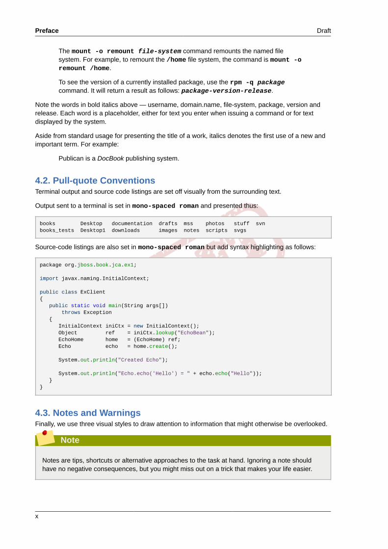
books Desktop documentation drafts mss photos stuff svnbooks_tests Desktop1 downloads images notes scripts svgs
Source-code listings are also set in mono-spaced roman but add syntax highlighting as follows:
package org.jboss.book.jca.ex1;
import javax.naming.InitialContext;
public class ExClient{ public static void main(String args[]) throws Exception { InitialContext iniCtx = new InitialContext(); Object ref = iniCtx.lookup("EchoBean"); EchoHome home = (EchoHome) ref; Echo echo = home.create();
System.out.println("Created Echo");
System.out.println("Echo.echo('Hello') = " + echo.echo("Hello")); }}
4.3. Notes and WarningsFinally, we use three visual styles to draw attention to information that might otherwise be overlooked.
Note
Notes are tips, shortcuts or alternative approaches to the task at hand. Ignoring a note shouldhave no negative consequences, but you might miss out on a trick that makes your life easier.

Draft Feedback
xi
Important
Important boxes detail things that are easily missed: configuration changes that only apply tothe current session, or services that need restarting before an update will apply. Ignoring a boxlabeled 'Important' will not cause data loss but may cause irritation and frustration.
Warning
Warnings should not be ignored. Ignoring warnings will most likely cause data loss.
5. Feedback
If you find a typographical error in this manual, or if you have thought of a way to make this manualbetter, we would love to hear from you! Please submit a report in Bugzilla3 against the product FedoraDocumentation.
When submitting a bug report, be sure to provide the following information:
• Manual's identifier: networking-guide
• Version number: 23
If you have a suggestion for improving the documentation, try to be as specific as possible whendescribing it. If you have found an error, please include the section number and some of thesurrounding text so we can find it easily.
6. AcknowledgmentsCertain portions of this text first appeared in the Red Hat Enterprise Linux 6 Deployment Guide,copyright © 2010—YEAR Red Hat, Inc., available at https://access.redhat.com/site/documentation/en-US/Red_Hat_Enterprise_Linux/6/html/Deployment_Guide/index.html.
3 http://bugzilla.redhat.com/

xii

Draft Draft
Part I. NetworkingThis part describes how to configure the network on Fedora.


Draft Chapter 1. Draft
3
Introduction to Fedora Networking
1.1. How this Book is StructuredAll new material in this book has been written and arranged in such a way as to clearly separateintroductory material, such as explanations of concepts and use cases, from configuration tasks. Theauthors hope that you can quickly find configuration instructions you need, while still providing somerelevant explanations and conceptual material to help you understand and decide on the appropriatetasks relevant to your needs. Where material has been reused from the Red Hat Enterprise Linux 6Deployment Guide1, it has been reviewed and changed, where possible, to fit this idea of separatingconcepts from tasks.
The material is grouped according to the goal rather than the method. Instructions on how to achievea specific task using different methods are grouped together. This is intended to make it easier for youto find the information on how to achieve a particular task or goal, and at the same time allow you toquickly see the different methods available.
In each chapter, the configuration methods will be presented in the following order: A graphical userinterface (GUI) method, such as the use of nm-connection-editor or control-network to directNetworkManager, then NetworkManager's command-line tool nmcli, and then finally methods usingthe command line and configuration files. The command line can be used to issue commands and tocompose or edit configuration files, therefore the use of the ip commands and configuration files willbe documented together.
1.2. Introduction to NetworkManagerAs of Fedora 20, the default networking service is provided by NetworkManager, which is a dynamicnetwork control and configuration daemon that attempts to keep network devices and connections upand active when they are available. The traditional ifcfg type configuration files are still supported.See Section 1.6, “NetworkManager and the Network Scripts” for more information.
Table 1.1. A Summary of Networking Tools and Applications
Application or Tool Description
NetworkManager The default networking daemon
nmtui A simple curses-based text user interface (TUI) for NetworkManager
nmcli A command-line tool provided to allow users and scripts to interactwith NetworkManager
control-center A graphical user interface tool provided by the GNOME Shell
nm-connection-editor A GTK+ 3 application available for certain tasks not yet handled bycontrol-center
NetworkManager can be used with the following types of connections: Ethernet, VLANs, Bridges,Bonds, Teams, Wi-Fi, mobile broadband (such as cellular 3G), and IP-over-InfiniBand. For theseconnection types, NetworkManager can configure network aliases, IP addresses, static routes,DNS information, and VPN connections, as well as many connection-specific parameters. Finally,NetworkManager provides an API via D-Bus which allows applications to query and control networkconfiguration and state.
1 https://access.redhat.com/site/documentation/en-US/Red_Hat_Enterprise_Linux/6/html/Deployment_Guide/index.html

Chapter 1. Introduction to Fedora Networking Draft
4
1.3. Installing NetworkManagerNetworkManager is installed by default on Fedora. If necessary, to ensure that it is, run the followingcommand as the root user:
~]# dnf install NetworkManager
For information on user privileges and gaining privileges, see the Fedora 23 System Administrator'sGuide.
1.3.1. The NetworkManager DaemonThe NetworkManager daemon runs with root privileges and is, by default, configured to start upat boot time. You can determine whether the NetworkManager daemon is running by entering thiscommand:
~]$ systemctl status NetworkManagerNetworkManager.service - Network Manager Loaded: loaded (/lib/systemd/system/NetworkManager.service; enabled) Active: active (running) since Fri, 08 Mar 2013 12:50:04 +0100; 3 days ago
The systemctl status command will report NetworkManager as Active: inactive (dead)if the NetworkManager service is not running. To start it for the current session run the followingcommand as the root user:
~]# systemctl start NetworkManager
Run the systemctl enable command to ensure that NetworkManager starts up every time thesystem boots:
~]# systemctl enable NetworkManager
For more information on starting, stopping and managing services, see the Fedora 23 SystemAdministrator's Guide.
1.3.2. Interacting with NetworkManagerUsers do not interact with the NetworkManager system service directly. Instead, users performnetwork configuration tasks via graphical and command-line user interface tools. The following toolsare available in Fedora:
1. A graphical user interface tool called control-center, provided by GNOME, is available fordesktop users. It incorporates a Network settings tool. It start it, press the Super key to enter theActivities Overview, type control network and then press Enter.
2. A command-line tool, nmcli, is provided to allow users and scripts to interact withNetworkManager. Note that nmcli can be used on GUI-less systems like servers to control allaspects of NetworkManager. It is on an equal footing with the GUI tools.
3. The GNOME Shell also provides a network icon in its Notification Area representing networkconnection states as reported by NetworkManager. The icon has multiple states that serve asvisual indicators for the type of connection you are currently using.
4. A graphical user interface tool called control-center, provided by the GNOME Shell, is availablefor desktop users. It incorporates a Network settings tool. To start it, press the Super key to enter

Draft Network Configuration Using the Command Line Interface (CLI)
5
the Activities Overview, type control network and then press Enter. The Super key appearsin a variety of guises, depending on the keyboard and other hardware, but often as either theWindows or Command key, and typically to the left of the Spacebar.
5. A graphical user interface tool, nm-connection-editor, is available for certain tasks not yethandled by control-center. To start it, press the Super key to enter the Activities Overview, typenetwork connections or nm-connection-editor and then press Enter.
1.4. Network Configuration Using the Command LineInterface (CLI)The commands for the ip utility, sometimes referred to as iproute2 after the upstream package name,are documented in the man ip(8) page. The package name in Fedora is iproute. If necessary, youcan check that the ip utility is installed by checking its version number as follows:
~]$ ip -Vip utility, iproute2-ss130716
The ip commands can be used to add and remove addresses and routes to interfaces in parallel withNetworkManager, which will preserve them and recognize them in nmcli, nmtui, control-center, andthe D-Bus API.
Note
Note that ip commands given on the command line will not persist after a system restart.
Examples of using the command line and configuration files for each task are included after explainingthe use of one of the graphical user interfaces to NetworkManager, namely, control-center and nm-connection-editor.
1.5. Network Configuration Using NetworkManager's CLI(nmcli)The NetworkManager command-line tool, nmcli, provides a command line way to configurenetworking by controlling NetworkManager. It is installed, along with NetworkManager, by default.If required, for details on how to verify that NetworkManager is running, see Section 1.3.1, “TheNetworkManager Daemon”.
Examples of using the nmcli tool for each task will be included where possible, after explainingthe use of graphical user interfaces and other command line methods. See Section 2.4, “Using theNetworkManager Command Line Tool, nmcli” for an introduction to nmcli.
1.6. NetworkManager and the Network ScriptsIn previous Red Hat Enterprise Linux releases, the default way to configure networking was usingnetwork scripts. The term network scripts is commonly used for the script /etc/init.d/networkand any other installed scripts it calls. The user supplied files are typically viewed as configuration, butcan also be interpreted as an amendment to the scripts.

Chapter 1. Introduction to Fedora Networking Draft
6
Although NetworkManager provides the default networking service, Red Hat developers have workedhard to ensure that scripts and NetworkManager cooperate with each other. Administrators who areused to the scripts can certainly continue to use them. We expect both systems to be able to run inparallel and work well together. It is expected that most user shell scripts from previous releases willstill work. Red Hat recommends that you test them first.
Running Network ScriptRun the script only with the systemctl utility which will clear any existing environment variables andensure clean execution. The command takes the following form:
systemctl start|stop|restart|status network
Do not run any service by calling /etc/init.d/servicename start|stop|restart|statusdirectly.
Note that in Red Hat Enterprise Linux 7, NetworkManager is started first, and /etc/init.d/network checks with NetworkManager to avoid tampering with NetworkManager's connections.NetworkManager is intended to be the primary application using sysconfig configuration files and /etc/init.d/network is intended to be secondary, playing a fallback role.
The /etc/init.d/network script is not event-driven, it runs either:1. manually (by one of the systemctl commands start|stop|restart network),
2. on boot and shutdown if the network service is enabled (as a result of the command systemctlenable network).
It is a manual process and does not react to events that happen after boot. Users can also call thescripts ifup and ifdown manually.
Custom Commands and the Network ScriptsCustom commands in the scripts /sbin/ifup-local, ifdown-pre-local, and ifdown-localare only executed when those devices are controlled by the /etc/init.d/network service. If youmodified the initscripts themselves (for example, /etc/sysconfig/network-scripts/ifup-eth)then those changes would be overwritten by an initscripts package update. Therefore it is recommendthat you avoid modifying the initscripts directly and make use of the /sbin/if*local scripts, so thatyour custom changes will survive package updates. The initscripts just check for the presence of therelevant /sbin/if*local and run them if they exit. The initscripts do not place anything in the /sbin/if*local scripts, nor does the initscripts RPM (or any package) own or modify those files.
There are ways to perform custom tasks when network connections go up and down, both withthe old network scripts and with NetworkManager. When NetworkManager is enabled, the ifupand ifdown script will ask NetworkManager whether NetworkManager manages the interface inquestion, which is found from the “DEVICE=” line in the ifcfg file. If NetworkManager does managethat device, and the device is not already connected, then ifup will ask NetworkManager to start theconnection.• If the device is managed by NetworkManager and it is already connected, nothing is done.
• If the device is not managed by NetworkManager, then the scripts will start the connectionusing the older, non-NetworkManager mechanisms that they have used since the time beforeNetworkManager existed.
If you are calling "ifdown" and the device is managed by NetworkManager, then ifdown will askNetworkManager to terminate the connection.

Draft Network Configuration Using sysconfig Files
7
The scripts dynamically check NetworkManager, so if NetworkManager is not running, the scriptswill fall back to the old, pre-NetworkManager script-based mechanisms.
1.7. Network Configuration Using sysconfig FilesThe /etc/sysconfig/ directory is a location for configuration files and scripts. Most networkconfiguration information is stored there, with the exception of VPN, mobile broadband and PPPoEconfiguration, which are stored in /etc/NetworkManager/ subdirectories. Interface specificinformation for example, is stored in ifcfg files in the /etc/sysconfig/network-scripts/directory.
The file /etc/sysconfig/network is for global settings. Information for VPNs, mobile broadbandand PPPoE connections is stored in /etc/NetworkManager/system-connections/.
In Fedora, when you edit an ifcfg file, NetworkManager is not automatically aware of the changeand has to be prompted to notice the change. If you use one of the tools to update NetworkManagerprofile settings, then NetworkManager does not implement those changes until you reconnect usingthat profile. For example, if configuration files have been changed using an editor, NetworkManagermust be told to read the configuration files again. To do that, issue the following command as root:
~]# nmcli connection reload
The above command reads all connection profiles. Alternatively, to reload only one changed file,ifcfg-ifname, issue a command as follows:
~]# nmcli con load /etc/sysconfig/network-scripts/ifcfg-ifname
The command accepts multiple file names. These commands require root privileges. For moreinformation on user privileges and gaining privileges, see the Fedora 23 System Administrator's Guideand the su(1) and sudo(8) man pages.
Changes made using tools such as nmcli do not require a reload but do require the associatedinterface to be put down and then up again. That can be done by using commands in the followingformat:
nmcli dev disconnect interface-name
Followed by:
nmcli con up interface-name
NetworkManager does not trigger any of the network scripts, though the network scripts will tryto trigger NetworkManager if it is running when ifup commands are used. See Section 1.6,“NetworkManager and the Network Scripts” for an explanation of the network scripts.
The ifup script is a generic script which does a few things and then calls interface-specific scripts likeifup-ethX, ifup-wireless, ifup-ppp, and so on. When a user runs ifup eth0 manually, thefollowing occurs:1. ifup looks for a file called /etc/sysconfig/network-scripts/ifcfg-eth0;
2. if the ifcfg file exists, ifup looks for the TYPE key in that file to determine which type-specificscript to call;
3. ifup calls ifup-wireless or ifup-eth or ifup-XXX based on TYPE;

Chapter 1. Introduction to Fedora Networking Draft
8
4. the type-specific scripts do type-specific setup;
5. and then the type-specific scripts let common functions perform IP-related tasks like DHCP orstatic setup.
On bootup, /etc/init.d/network reads through all the ifcfg files and for each one that hasONBOOT=yes, it checks whether NetworkManager is already starting the DEVICE from that ifcfgfile. If NetworkManager is starting that device or has already started it, nothing more is done for thatfile, and the next ONBOOT=yes file is checked. If NetworkManager is not yet starting that device, theinitscripts will continue with their traditional behavior and call ifup for that ifcfg file.
The end result is that any ifcfg file that has ONBOOT=yes is expected to be started on systembootup, either by NetworkManager or by the initscripts. This ensures that some legacy network typeswhich NetworkManager does not handle (such as ISDN or analog dialup modems) as well as anynew application not yet supported by NetworkManager are still correctly started by the initscripts eventhough NetworkManager is unable to handle them.
Note
It is recommended not to store backup ifcfg files in the same location as the live ones. Thescript literally does ifcfg-* with an exclude only for these extensions: .old, .orig, .rpmnew,.rpmorig, and .rpmsave. The best way is not to store backup files anywhere within the /etc/directory.
1.8. Additional ResourcesThe following sources of information provide additional resources regarding networking for Fedora.
1.8.1. Installed Documentation• man(1) man page — Describes man pages and how to find them.
• NetworkManager(8) man page — Describes the network management daemon.
• NetworkManager.conf(5) man page — Describes the NetworkManager configuration file.
• /usr/share/doc/initscripts-version/sysconfig.txt — Describes configuration filesand their directives.

Draft Chapter 2. Draft
9
Configure Networking
2.1. Static and Dynamic Interface SettingsWhen to use static addressing and when to use dynamic addressing? These decisions are subjective,they depend on your accessed needs, your specific requirements. Having a policy, documenting it,and applying it consistently are usually more important than the specific decisions you make. In atraditional company LAN, this is an easier decision to make as you typically have fewer servers thanother hosts. Provisioning and installation tools make providing static configurations to new hostseasy and using such tools will change your work flow and requirements. The following two sectionsare intended to provide guidance to those who have not already been through this decision-makingprocess. For more information on automated configuration and management, see the OpenLMIsection in the System Administrators Guide. The System Installation Guide documents the use ofkickstart which can also be used for automating the assignment of network settings.
2.1.1. When to Use Static Network Interface Settings
Use static IP addressing on those servers and devices whose network availability you want to ensurewhen automatic assignment methods, such as DHCP, fail. DHCP, DNS, and authentication servers aretypical examples. Interfaces for out-of-band management devices are also worth configuring with staticsettings as these devices are supposed to work, as far as is possible, independently of other networkinfrastructure.
For hosts which are not considered vital, but for which static IP addressing is still considereddesirable, use an automated provisioning method when possible. For example, DHCP servers can beconfigured to provide the same IP address to the same host every time. This method could be usedfor communal printers for example.
All the configuration tools listed in Section 2.1.3, “Selecting Network Configuration Methods”allow assigning static IP addresses manually. The nmcli tool is also suitable for use with scriptedassignment of network configuration.
2.1.2. When to Use Dynamic Interface Settings
Enable and use dynamic assignment of IP addresses and other network information whenever thereis no compelling reason not to. The time saved in planning and documenting manual settings canbe better spent elsewhere. The dynamic host control protocol (DHCP) is a traditional method ofdynamically assigning network configurations to hosts. See Section 9.1, “Why Use DHCP?” for moreinformation on this subject.
NetworkManager will by default call the DHCP client, dhclient, when a profile has been set to obtainaddresses automatically, or when an interface configuration file has BOOTPROTO set to dhcp. WhereDHCP is required, an instance of dhclient is started for every Internet protocol, IPv4 and IPv6, onan interface. Where NetworkManager is not running, or not managing an interface, then the legacynetwork service will call instances of dhclient as required.
2.1.3. Selecting Network Configuration Methods• To configure a network using graphical user interface tools, proceed to Section 2.2, “Using
NetworkManager with the GNOME Graphical User Interface”
• To configure a network interface manually, see Section 2.3, “Using the Command Line Interface(CLI)”.

Chapter 2. Configure Networking Draft
10
• To configure an interface using NetworkManager's command-line tool, nmcli, proceed toSection 2.4, “Using the NetworkManager Command Line Tool, nmcli”
2.2. Using NetworkManager with the GNOME GraphicalUser InterfaceAs of Fedora 20, NetworkManager's own graphical user interface (GUI) is not used by default. TheNetwork settings configuration tool is provided as part of the new GNOME control-center GUI. Theold nm-connection-editor GUI is still available for certain tasks.
2.2.1. Connecting to a Network Using a GUIAccess the Network settings window of the control-center application as follows:
• Press the Super key to enter the Activities Overview, type control network and then pressEnter. The Network settings tool appears. Proceed to Section 2.2.2, “Configuring New and EditingExisting Connections”
2.2.2. Configuring New and Editing Existing ConnectionsThe Network settings window shows the connection status, its type and interface, its IP address androuting details, and so on.
Figure 2.1. Configure Networks Using the Network Settings Window
The Network settings window has a menu on the left-hand side showing the available networkdevices or interfaces. This includes software interfaces such as for VLANs, bridges, bonds, andteams. On the right-hand side, the connection profiles are shown for the selected network device orinterface. A profile is a named collection of settings that can be applied to an interface. Below thatis a plus and a minus button for adding and deleting new network connections, and on the right agear wheel icon will appear for editing the connection details of the selected network device or VPNconnection. To add a new connection, click the plus symbol to open the Add Network Connectionwindow and proceed to Section 2.2.2.1, “Configuring a New Connection”.
Editing an Existing ConnectionClicking on the gear wheel icon of an existing connection profile in the Network settings windowopens the Network details window, from where you can perform most network configuration taskssuch as IP addressing, DNS, and routing configuration.

Draft Connecting to a Network Automatically
11
Figure 2.2. Configure Networks Using the Network Connection Details Window
2.2.2.1. Configuring a New ConnectionIn the Network settings window, click the plus sign below the menu to open the Add NetworkConnection window. This displays a list of connection types that can be added.
Then, to configure:
• VPN connections, click the VPN entry and proceed to Section 2.2.7, “Establishing a VPNConnection”;
• Bond connections, click the Bond entry and proceed to Section 4.2.1, “Establishing a BondConnection”;
• Bridge connections, click the Bridge entry and proceed to Section 6.1.1, “Establishing a BridgeConnection”;
• VLAN connections, click the VLAN entry and proceed to Section 7.2.1, “Establishing a VLANConnection”;or,
• Team connections, click the Team entry and proceed to Section 5.9, “Creating a Network TeamUsing a GUI”.
2.2.3. Connecting to a Network AutomaticallyFor any connection type you add or configure, you can choose whether you want NetworkManager totry to connect to that network automatically when it is available.
Procedure 2.1. Configuring NetworkManager to Connect to a Network Automatically When Detected1. Press the Super key to enter the Activities Overview, type control network and then press
Enter. The Network settings tool appears.
2. Select the network interface from the left-hand-side menu.
3. Click on the gear wheel icon of a connection profile on the right-hand side menu. If you have onlyone profile associated with the selected interface the gear wheel icon will be in the lower right-hand-side corner. The Network details window appears.
4. Select the Identity menu entry on the left. The Network window changes to the identity view.

Chapter 2. Configure Networking Draft
12
5. Select Connect automatically to cause NetworkManager to auto-connect to the connectionwhenever NetworkManager detects that it is available. Clear the check box if you do not wantNetworkManager to connect automatically. If the check box is clear, you will have to select thatconnection manually in the network settings tool to cause it to connect.
2.2.4. System-wide and Private Connection ProfilesNetworkManager stores all connection profiles. A profile is a named collection of settings that canbe applied to an interface. NetworkManager stores these connection profiles for system-wide use(system connections), as well as all user connection profiles. Access to the connection profiles iscontrolled by permissions which are stored by NetworkManager. See the nm-settings(5) manpage for more information on the connection settings permissions property. The permissionscorrespond to the USERS directive in the ifcfg files. If the USERS directive is not present, the networkprofile will be available to all users. As an example, the following command in an ifcfg file will makethe connection available only to the users listed:
USERS="joe bob alice"
This can also be set using graphical user interface tools. In nm-connection-editor, there is thecorresponding All users may connect to this network check box on the General tab, and in theGNOME control-center Network settings Identity window, there is the Make available to other userscheck box.
NetworkManager's default policy is to allow all users to create and modify system-wide connections.Profiles that should be available at boot time cannot be private because they will not be visible untilthe user logs in. For example, if user user creates a connection profile user-em2 with the ConnectAutomatically check box selected but with the Make available to other users not selected, then theconnection will not be available at boot time.
To restrict connections and networking, there are two options which can be used alone or incombination:• Clear the Make available to other users check box, which changes the connection to be modifiable
and usable only by the user doing the changing.
• Use the polkit framework to restrict permissions of general network operations on a per-user basis.
The combination of these two options provides fine-grained security and control over networking. Seethe polkit(8) man page for more information on polkit.
Note that VPN connections are always created as private-per-user, since they are assumed to bemore private than a Wi-Fi or Ethernet connection.
Procedure 2.2. Changing a Connection to Be User-specific Instead of System-Wide, or Vice VersaDepending on the system's policy, you may need root privileges on the system in order to changewhether a connection is user-specific or system-wide.
1. Press the Super key to enter the Activities Overview, type control network and then pressEnter. The Network settings tool appears.
2. Select the network interface from the left-hand-side menu.
3. Click on the gear wheel icon of a connection profile on the right-hand side menu. If you have onlyone profile associated with the selected interface the gear wheel icon will be in the lower right-hand-side corner. The Network details window appears.
4. Select the Identity menu entry on the left. The Network window changes to the identity view.

Draft Configuring a Wired (Ethernet) Connection
13
5. Select the Make available to other users check box to cause NetworkManager to make theconnection available system-wide. Depending on system policy, you may then be prompted for anadministrator or root password by the polkit application. If so, enter the appropriate password tofinalize the changes.
Conversely, clear the Make available to other users check box to make the connection user-specific.
2.2.5. Configuring a Wired (Ethernet) ConnectionTo configure a wired network connection, press the Super key to enter the Activities Overview, typecontrol network and then press Enter. The Network settings tool appears.
Select the Wired network interface from the left-hand-side menu if it is not already highlighted.
The system creates and configures a single wired connection profile called Wired by default. A profileis a named collection of settings that can be applied to an interface. More than one profile can becreated for an interface and applied as needed. The default profile cannot be deleted but its settingscan be changed. You can edit the default Wired profile by clicking the gear wheel icon. You can createa new wired connection profile by clicking the Add Profile button. Connection profiles associated witha selected interface are shown on the right-hand side menu.
When you add a new connection by clicking the Add Profile button, NetworkManager creates anew configuration file for that connection and then opens the same dialog that is used for editing anexisting connection. The difference between these dialogs is that an existing connection profile hasa Details and Reset menu entry. In effect, you are always editing a connection profile; the differenceonly lies in whether that connection previously existed or was just created by NetworkManager whenyou clicked Add Profile.
2.2.5.1. Configuring the Connection Name, Auto-Connect Behavior, andAvailability SettingsMany settings in the Editing dialog are common to all connection types, see the Identity view if usingthe GNOME tool or the General tab if using nm-connection-editor:
• Name — Enter a descriptive name for your network connection. This name will be used to list thisconnection in the menu of the Network window.
• MAC Address — Select the MAC address of the interface this profile must be applied to.
• Cloned Address — If required, enter a different MAC address to use.
• MTU — If required, enter a specific maximum transmission unit (MTU) to use. The MTU valuerepresents the size in bytes of the largest packet that the link-layer will transmit. This value defaultsto 1500 and does not generally need to be specified or changed.
• Firewall Zone — If required, select a different firewall zone to apply. See the Red HatEnterprise Linux 7 Security Guide1 for more information on firewall zones.
• Connect Automatically — Select this box if you want NetworkManager to auto-connect to thisconnection when it is available. See Section 2.2.3, “Connecting to a Network Automatically” for moreinformation.
1 https://access.redhat.com/documentation/en-US/Red_Hat_Enterprise_Linux/7/html/Security_Guide/

Chapter 2. Configure Networking Draft
14
• Make available to other users — Select this box to create a connection available to all users onthe system. Changing this setting may require root privileges. See Section 2.2.4, “System-wide andPrivate Connection Profiles” for details.
• Automatically connect to VPN when using this connection — Select this box if you wantNetworkManager to auto-connect to the selected VPN connection when this connection profile isconnected. Select the VPN from the drop-down menu.
Saving Your New (or Modified) Connection and Making Further ConfigurationsOnce you have finished editing your wired connection, click the Apply button to save your customizedconfiguration. If the profile was in use while being edited, power cycle the connection to makeNetworkManager apply the changes. If the profile is OFF, set it to ON. See Section 2.2.1, “Connectingto a Network Using a GUI” for information on using your new or altered connection.
You can further configure an existing connection by selecting it in the Network window and clicking thegear wheel icon to return to the editing dialog.
Then, to configure:
• port-based Network Access Control (PNAC), click the 802.1X Security tab and proceed toSection 2.2.10.1, “Configuring 802.1X Security”;
• IPv4 settings for the connection, click the IPv4 Settings tab and proceed to Section 2.2.10.4,“Configuring IPv4 Settings”; or,
• IPv6 settings for the connection, click the IPv6 Settings tab and proceed to Section 2.2.10.5,“Configuring IPv6 Settings”.
2.2.6. Configuring a Wi-Fi ConnectionThis section explains how to use NetworkManager to configure a Wi-Fi (also known as wireless or802.11a/b/g/n) connection to an Access Point.
To configure a mobile broadband (such as 3G) connection, see Section 2.2.8, “Establishing a MobileBroadband Connection”.
Quickly Connecting to an Available Access PointThe easiest way to connect to an available access point is to click on the network connection icon toactivate the network connection, locate the Service Set Identifier (SSID) of the access point in the listof Wi-Fi networks, and click on it. A padlock symbol indicates the access point requires authentication.If the access point is secured, a dialog prompts you for an authentication key or password.
NetworkManager tries to auto-detect the type of security used by the access point. If there aremultiple possibilities, NetworkManager guesses the security type and presents it in the Wi-Fisecurity drop-down menu. For WPA-PSK security (WPA with a passphrase) no choice is necessary.For WPA Enterprise (802.1X) you have to specifically select the security, because that cannot be auto-detected. If you are unsure, try connecting to each type in turn. Finally, enter the key or passphrasein the Password field. Certain password types, such as a 40-bit WEP or 128-bit WPA key, are invalidunless they are of a requisite length. The Connect button will remain inactive until you enter a keyof the length required for the selected security type. To learn more about wireless security, seeSection 2.2.10.2, “Configuring Wi-Fi Security”.
If NetworkManager connects to the access point successfully, the network connection icon willchange into a graphical indicator of the wireless connection's signal strength.

Draft Configuring a Wi-Fi Connection
15
You can also edit the settings for one of these auto-created access point connections just as if you hadadded it yourself. The Wi-Fi page of the Network window has a History button. Clicking it reveals alist of all the connections you have ever tried to connect to. See Section 2.2.6.2, “Editing a Connection,or Creating a Completely New One”
2.2.6.1. Connecting to a Hidden Wi-Fi NetworkAll access points have a Service Set Identifier (SSID) to identify them. However, an access pointmay be configured not to broadcast its SSID, in which case it is hidden, and will not show up inNetworkManager's list of Available networks. You can still connect to a wireless access point that ishiding its SSID as long as you know its SSID, authentication method, and secrets.
To connect to a hidden wireless network, press the Super key to enter the Activities Overview,type control network and then press Enter. The Network window appears. Select Wi-Fi fromthe menu and then select Connect to Hidden Network to cause a dialog to appear. If you haveconnected to the hidden network before, use the Connection drop-down to select it, and clickConnect. If you have not, leave the Connection drop-down as New, enter the SSID of the hiddennetwork, select its Wi-Fi security method, enter the correct authentication secrets, and click Connect.
For more information on wireless security settings, see Section 2.2.10.2, “Configuring Wi-Fi Security”.
2.2.6.2. Editing a Connection, or Creating a Completely New OneYou can edit an existing connection that you have tried or succeeded in connecting to in the past byopening the Wi-Fi page of the Network dialog and selecting the gear wheel icon to the right of the Wi-Fi connection name. If the network is not currently in range, click History to display past connections.When you click the gear wheel icon the editing connection dialog appears. The Details window showsthe connection details.
To configure a new connection whose SSID is in range, first attempt to connect to it by opening theNetwork window, selecting the Wi-Fi menu entry, and clicking the connection name (by default, thesame as the SSID). If the SSID is not in range, see Section 2.2.6.1, “Connecting to a Hidden Wi-FiNetwork”. If the SSID is in range, the procedure is as follows:
1. Press the Super key to enter the Activities Overview, type control network and then pressEnter. The Network settings tool appears.
2. Select the Wi-Fi interface from the left-hand-side menu entry.
3. Click the Wi-Fi connection profile on the right-hand side menu you want to connect to. A padlocksymbol indicates a key or password is required.
4. If requested, enter the authentication details.
Configuring the SSID, Auto-Connect Behavior, and Availability SettingsTo edit a Wi-Fi connection's settings, select Wi-Fi in the Network page and then select the gear wheelicon to the right of the Wi-Fi connection name. Select Identity. The following settings are available:
SSIDThe Service Set Identifier (SSID) of the access point (AP).
BSSIDThe Basic Service Set Identifier (BSSID) is the MAC address, also known as a hardware address,of the specific wireless access point you are connecting to when in Infrastructure mode. This fieldis blank by default, and you are able to connect to a wireless access point by SSID without having

Chapter 2. Configure Networking Draft
16
to specify its BSSID. If the BSSID is specified, it will force the system to associate to a specificaccess point only.
For ad-hoc networks, the BSSID is generated randomly by the mac80211 subsystem when thead-hoc network is created. It is not displayed by NetworkManager
MAC addressSelect the MAC address, also known as a hardware address, of the Wi-Fi interface to use.
A single system could have one or more wireless network adapters connected to it. The MACaddress field therefore allows you to associate a specific wireless adapter with a specificconnection (or connections).
Cloned AddressA cloned MAC address to use in place of the real hardware address. Leave blank unless required.
The following settings are common to all connection profiles:
• Connect automatically — Select this box if you want NetworkManager to auto-connect to thisconnection when it is available. See Section 2.2.3, “Connecting to a Network Automatically” for moreinformation.
• Make available to other users — Select this box to create a connection available to all users onthe system. Changing this setting may require root privileges. See Section 2.2.4, “System-wide andPrivate Connection Profiles” for details.
Saving Your New (or Modified) Connection and Making Further ConfigurationsOnce you have finished editing the wireless connection, click the Apply button to save yourconfiguration. Given a correct configuration, you can connect to your modified connection by selectingit from the GNOME Shell notification area menu in the top right-hand corner of the screen. Click inthe top right-hand side corner to open the menu. Select Wi-Fi. See Section 2.2.1, “Connecting to aNetwork Using a GUI” for details on selecting and connecting to a network.
You can further configure an existing connection by selecting it in the Network window and clicking thegear wheel icon to reveal the connection details.
Then, to configure:
• security authentication for the wireless connection, click Security and proceed to Section 2.2.10.2,“Configuring Wi-Fi Security”;
• IPv4 settings for the connection, click IPv4 and proceed to Section 2.2.10.4, “Configuring IPv4Settings”; or,
• IPv6 settings for the connection, click IPv6 and proceed to Section 2.2.10.5, “Configuring IPv6Settings”.
2.2.7. Establishing a VPN ConnectionEstablishing a Virtual Private Network (VPN) enables communication between your Local AreaNetwork (LAN), and another, remote LAN. This is done by setting up a tunnel across an intermediatenetwork such as the Internet. The VPN tunnel that is set up typically uses authentication andencryption. After successfully establishing a VPN connection using a secure tunnel, a VPN router orgateway performs the following actions upon the packets you transmit:
1. it adds an Authentication Header for routing and authentication purposes;

Draft Establishing a VPN Connection
17
2. it encrypts the packet data; and,
3. it encloses the data in packets according to the Encapsulating Security Payload (ESP) protocol,which constitutes the decryption and handling instructions.
The receiving VPN router strips the header information, decrypts the data, and routes it to its intendeddestination (either a workstation or other node on a network). Using a network-to-network connection,the receiving node on the local network receives the packets already decrypted and ready forprocessing. The encryption and decryption process in a network-to-network VPN connection istherefore transparent to clients.
Because they employ several layers of authentication and encryption, VPNs are a secure and effectivemeans of connecting multiple remote nodes to act as a unified intranet.
Procedure 2.3. Adding a New VPN ConnectionYou can configure a new VPN connection by opening the Network window and selecting the plussymbol below the menu.
1. Press the Super key to enter the Activities Overview, type control network and then pressEnter. The Network settings tool appears.
2. Select the plus symbol below the menu. The Add Network Connection window appears.
3. Select the VPN menu entry. The view now changes to offer configuring a VPN manually, orimporting a VPN configuration file.
The appropriate NetworkManager VPN plug-in for the VPN type you want to configure must beinstalled. (see Fedora 23 System Administrator's Guide for more information on how to install newpackages in Fedora 23).
4. Click the Add button to open the Choose a VPN Connection Type assistant.
5. Select the VPN protocol for the gateway you are connecting to from the menu. The VPN protocolsavailable for selection in the menu correspond to the NetworkManager VPN plug-ins installed.For example, if the NetworkManager-openswan-gnome package is installed then the IPsec basedVPN will be selectable from the menu.
6. The Add Network Connection window changes to present the settings customized for the typeof VPN connection you selected in the previous step.
Procedure 2.4. Editing an Existing VPN ConnectionYou can configure an existing VPN connection by opening the Network window and selecting thename of the connection from the list. Then click the Edit button.
1. Press the Super key to enter the Activities Overview, type control network and then pressEnter. The Network settings tool appears.
2. Select the VPN connection you want to edit from the left hand menu.
3. Click the Configure button.
Configuring the Connection Name, Auto-Connect Behavior, andAvailability SettingsFive settings in the Editing dialog are common to all connection types, see the General tab:
• Connection name — Enter a descriptive name for your network connection. This name will be usedto list this connection in the menu of the Network window.

Chapter 2. Configure Networking Draft
18
• Automatically connect to this network when it is available — Select this box if you wantNetworkManager to auto-connect to this connection when it is available. See Section 2.2.3,“Connecting to a Network Automatically” for more information.
• All users may connect to this network — Select this box to create a connection available to allusers on the system. Changing this setting may require root privileges. See Section 2.2.4, “System-wide and Private Connection Profiles” for details.
• Automatically connect to VPN when using this connection — Select this box if you wantNetworkManager to auto-connect to a VPN connection when it is available. Select the VPN fromthe drop-down menu.
• Firewall Zone — Select the Firewall Zone from the dropdown menu.
Configuring the VPN Tab Gateway
The name or IP address of the remote VPN gateway.
Group nameThe name of a VPN group configured on the remote gateway.
User passwordIf required, enter the password used to authenticate with the VPN.
Group passwordIf required, enter the password used to authenticate with the VPN.
User nameIf required, enter the user name used to authenticate with the VPN.
Phase1 AlgorithmsIf required, enter the algorithms to be used to authenticate and set up an encrypted channel.
Phase2 AlgorithmsIf required, enter the algorithms to be used for the IPsec negotiations.
DomainIf required, enter the Domain Name.
Saving Your New (or Modified) Connection and Making FurtherConfigurationsOnce you have finished editing your new VPN connection, click the Save button to save yourcustomized configuration. If the profile was in use while being edited, power cycle the connectionto make NetworkManager apply the changes. If the profile is OFF, set it to ON. See Section 2.2.1,“Connecting to a Network Using a GUI” for information on using your new or altered connection.
You can further configure an existing connection by selecting it in the Network window and clickingConfigure to return to the Editing dialog.
Then, to configure:
• IPv4 settings for the connection, click the IPv4 Settings tab and proceed to Section 2.2.10.4,“Configuring IPv4 Settings”.

Draft Establishing a Mobile Broadband Connection
19
2.2.8. Establishing a Mobile Broadband ConnectionYou can use NetworkManager's mobile broadband connection abilities to connect to the following 2Gand 3G services:
• 2G — GPRS (General Packet Radio Service), EDGE (Enhanced Data Rates for GSM Evolution), orCDMA (Code Division Multiple Access).
• 3G — UMTS (Universal Mobile Telecommunications System), HSPA (High Speed Packet Access),or EVDO (EVolution Data-Only).
Your computer must have a mobile broadband device (modem), which the system has discovered andrecognized, in order to create the connection. Such a device may be built into your computer (as isthe case on many notebooks and netbooks), or may be provided separately as internal or externalhardware. Examples include PC card, USB Modem or Dongle, mobile or cellular telephone capable ofacting as a modem.
Procedure 2.5. Adding a New Mobile Broadband ConnectionYou can configure a mobile broadband connection by opening the Network Connections tool andselecting the Mobile Broadband tab.
1. Press the Super key to enter the Activities Overview, type nm-connection-editor and thenpress Enter. The Network Connections tool appears.
2. Click the Add button. The Choose a Connection Type menu opens.
3. Select the Mobile Broadband menu entry.
4. Click Create to open the Set up a Mobile Broadband Connection assistant.
5. Under Create a connection for this mobile broadband device, choose the 2G- or 3G-capabledevice you want to use with the connection. If the drop-down menu is inactive, this indicatesthat the system was unable to detect a device capable of mobile broadband. In this case, clickCancel, ensure that you do have a mobile broadband-capable device attached and recognized bythe computer and then retry this procedure. Click the Continue button.
6. Select the country where your service provider is located from the list and click the Continuebutton.
7. Select your provider from the list or enter it manually. Click the Continue button.
8. Select your payment plan from the drop-down menu and confirm the Access Point Name (APN) iscorrect. Click the Continue button.
9. Review and confirm the settings and then click the Apply button.
10. Edit the mobile broadband-specific settings by referring to Section 2.2.8.1, “Configuring the MobileBroadband Tab”.
Procedure 2.6. Editing an Existing Mobile Broadband ConnectionFollow these steps to edit an existing mobile broadband connection.
1. Press the Super key to enter the Activities Overview, type nm-connection-editor and thenpress Enter. The Network Connections tool appears.
2. Select the Mobile Broadband tab.
3. Select the connection you want to edit and click the Edit button.

Chapter 2. Configure Networking Draft
20
4. Configure the connection name, auto-connect behavior, and availability settings.
Five settings in the Editing dialog are common to all connection types, see the General tab:
• Connection name — Enter a descriptive name for your network connection. This name will beused to list this connection in the menu of the Network window.
• Automatically connect to this network when it is available — Select this box if you wantNetworkManager to auto-connect to this connection when it is available. See Section 2.2.3,“Connecting to a Network Automatically” for more information.
• All users may connect to this network — Select this box to create a connection available toall users on the system. Changing this setting may require root privileges. See Section 2.2.4,“System-wide and Private Connection Profiles” for details.
• Automatically connect to VPN when using this connection — Select this box if you wantNetworkManager to auto-connect to a VPN connection when it is available. Select the VPNfrom the drop-down menu.
• Firewall Zone — Select the Firewall Zone from the drop-down menu.
5. Edit the mobile broadband-specific settings by referring to Section 2.2.8.1, “Configuring the MobileBroadband Tab”.
Saving Your New (or Modified) Connection and Making FurtherConfigurationsOnce you have finished editing your mobile broadband connection, click the Apply button to saveyour customized configuration. If the profile was in use while being edited, power cycle the connectionto make NetworkManager apply the changes. If the profile is OFF, set it to ON. See Section 2.2.1,“Connecting to a Network Using a GUI” for information on using your new or altered connection.
You can further configure an existing connection by selecting it in the Network Connections windowand clicking Edit to return to the Editing dialog.
Then, to configure:
• Point-to-point settings for the connection, click the PPP Settings tab and proceed toSection 2.2.10.3, “Configuring PPP (Point-to-Point) Settings”;
• IPv4 settings for the connection, click the IPv4 Settings tab and proceed to Section 2.2.10.4,“Configuring IPv4 Settings”; or,
• IPv6 settings for the connection, click the IPv6 Settings tab and proceed to Section 2.2.10.5,“Configuring IPv6 Settings”.
2.2.8.1. Configuring the Mobile Broadband TabIf you have already added a new mobile broadband connection using the assistant (seeProcedure 2.5, “Adding a New Mobile Broadband Connection” for instructions), you can edit theMobile Broadband tab to disable roaming if home network is not available, assign a network ID,or instruct NetworkManager to prefer a certain technology (such as 3G or 2G) when using theconnection.

Draft Establishing a DSL Connection
21
NumberThe number that is dialed to establish a PPP connection with the GSM-based mobile broadbandnetwork. This field may be automatically populated during the initial installation of the broadbanddevice. You can usually leave this field blank and enter the APN instead.
UsernameEnter the user name used to authenticate with the network. Some providers do not provide a username, or accept any user name when connecting to the network.
PasswordEnter the password used to authenticate with the network. Some providers do not provide apassword, or accept any password.
APNEnter the Access Point Name (APN) used to establish a connection with the GSM-based network.Entering the correct APN for a connection is important because it often determines:
• how the user is billed for their network usage; and/or
• whether the user has access to the Internet, an intranet, or a subnetwork.
Network IDEntering a Network ID causes NetworkManager to force the device to register only to a specificnetwork. This can be used to ensure the connection does not roam when it is not possible tocontrol roaming directly.
TypeAny — The default value of Any leaves the modem to select the fastest network.
3G (UMTS/HSPA) — Force the connection to use only 3G network technologies.
2G (GPRS/EDGE) — Force the connection to use only 2G network technologies.
Prefer 3G (UMTS/HSPA) — First attempt to connect using a 3G technology such as HSPA orUMTS, and fall back to GPRS or EDGE only upon failure.
Prefer 2G (GPRS/EDGE) — First attempt to connect using a 2G technology such as GPRS orEDGE, and fall back to HSPA or UMTS only upon failure.
Allow roaming if home network is not availableUncheck this box if you want NetworkManager to terminate the connection rather than transitionfrom the home network to a roaming one, thereby avoiding possible roaming charges. If the boxis checked, NetworkManager will attempt to maintain a good connection by transitioning from thehome network to a roaming one, and vice versa.
PINIf your device's SIM (Subscriber Identity Module) is locked with a PIN (Personal IdentificationNumber), enter the PIN so that NetworkManager can unlock the device. NetworkManager mustunlock the SIM if a PIN is required in order to use the device for any purpose.
CDMA and EVDO have fewer options. They do not have the APN, Network ID, or Type options.
2.2.9. Establishing a DSL ConnectionThis section is intended for those installations which have a DSL card fitted within a host ratherthan the external combined DSL modem router combinations typical of private consumer or SOHOinstallations.

Chapter 2. Configure Networking Draft
22
Procedure 2.7. Adding a New DSL ConnectionYou can configure a new DSL connection by opening the Network Connections window, clicking theAdd button and selecting DSL from the Hardware section of the new connection list.
1. Press the Super key to enter the Activities Overview, type nm-connection-editor and thenpress Enter. The Network Connections tool appears.
2. Click the Add button.
3. The Choose a Connection Type list appears.
4. Select DSL and press the Create button.
5. The Editing DSL Connection 1 window appears.
Procedure 2.8. Editing an Existing DSL ConnectionYou can configure an existing DSL connection by opening the Network Connections window andselecting the name of the connection from the list. Then click the Edit button.
1. Press the Super key to enter the Activities Overview, type nm-connection-editor and thenpress Enter. The Network Connections tool appears.
2. Select the connection you want to edit and click the Edit button.
Configuring the Connection Name, Auto-Connect Behavior, andAvailability SettingsFive settings in the Editing dialog are common to all connection types, see the General tab:
• Connection name — Enter a descriptive name for your network connection. This name will be usedto list this connection in the menu of the Network window.
• Automatically connect to this network when it is available — Select this box if you wantNetworkManager to auto-connect to this connection when it is available. See Section 2.2.3,“Connecting to a Network Automatically” for more information.
• All users may connect to this network — Select this box to create a connection available to allusers on the system. Changing this setting may require root privileges. See Section 2.2.4, “System-wide and Private Connection Profiles” for details.
• Automatically connect to VPN when using this connection — Select this box if you wantNetworkManager to auto-connect to a VPN connection when it is available. Select the VPN fromthe drop-down menu.
• Firewall Zone — Select the Firewall Zone from the drop-down menu.
Configuring the DSL Tab Username
Enter the user name used to authenticate with the service provider.
ServiceLeave blank unless otherwise directed by your service provider.
PasswordEnter the password supplied by the service provider.

Draft Configuring Connection Settings
23
Saving Your New (or Modified) Connection and Making FurtherConfigurationsOnce you have finished editing your DSL connection, click the Apply button to save your customizedconfiguration. If the profile was in use while being edited, power cycle the connection to makeNetworkManager apply the changes. If the profile is OFF, set it to ON. See Section 2.2.1, “Connectingto a Network Using a GUI” for information on using your new or altered connection.
You can further configure an existing connection by selecting it in the Network Connections windowand clicking Edit to return to the Editing dialog.
Then, to configure:
• The MAC address and MTU settings, click the Wired tab and proceed to Section 2.2.5.1,“Configuring the Connection Name, Auto-Connect Behavior, and Availability Settings”;
• Point-to-point settings for the connection, click the PPP Settings tab and proceed toSection 2.2.10.3, “Configuring PPP (Point-to-Point) Settings”;
• IPv4 settings for the connection, click the IPv4 Settings tab and proceed to Section 2.2.10.4,“Configuring IPv4 Settings”.
2.2.10. Configuring Connection Settings
2.2.10.1. Configuring 802.1X Security802.1X security is the name of the IEEE standard for port-based Network Access Control (PNAC). Itis also called WPA Enterprise. Simply put, 802.1X security is a way of controlling access to a logicalnetwork from a physical one. All clients who want to join the logical network must authenticate with theserver (a router, for example) using the correct 802.1X authentication method.
802.1X security is most often associated with securing wireless networks (WLANs), but can alsobe used to prevent intruders with physical access to the network (LAN) from gaining entry. In thepast, DHCP servers were configured not to lease IP addresses to unauthorized users, but for variousreasons this practice is both impractical and insecure, and thus is no longer recommended. Instead,802.1X security is used to ensure a logically-secure network through port-based authentication.
802.1X provides a framework for WLAN and LAN access control and serves as an envelope forcarrying one of the Extensible Authentication Protocol (EAP) types. An EAP type is a protocol thatdefines how security is achieved on the network.
You can configure 802.1X security for a wired or wireless connection type by opening the Networkwindow (see Section 2.2.1, “Connecting to a Network Using a GUI”) and following the applicableprocedure below. Press the Super key to enter the Activities Overview, type control networkand then press Enter. The Network settings tool appears. Proceed to Procedure 2.9, “For a WiredConnection” or Procedure 2.10, “For a Wireless Connection”:
Procedure 2.9. For a Wired Connection1. Select a Wired network interface from the left-hand-side menu.
2. Either click on Add Profile to add a new network connection profile for which you want toconfigure 802.1X security, or select an existing connection profile and click the gear wheel icon.
3. Then select Security and set the symbolic power button to ON to enable settings configuration.
4. Proceed to Section 2.2.10.1.1, “Configuring TLS (Transport Layer Security) Settings”

Chapter 2. Configure Networking Draft
24
Procedure 2.10. For a Wireless Connection1. Select a Wireless network interface from the left-hand-side menu. If necessary, set the symbolic
power button to ON and check that your hardware switch is on.
2. Either select the connection name of a new connection, or click the gear wheel icon of anexisting connection profile, for which you want to configure 802.1X security. In the case of a newconnection, complete any authentication steps to complete the connection and then click the gearwheel icon.
3. Select Security.
4. From the drop-down menu select one of the following security methods: LEAP, Dynamic WEP(802.1X), or WPA & WPA2 Enterprise.
5. Refer to Section 2.2.10.1.1, “Configuring TLS (Transport Layer Security) Settings” for descriptionsof which extensible authentication protocol (EAP) types correspond to your selection in theSecurity drop-down menu.
2.2.10.1.1. Configuring TLS (Transport Layer Security) SettingsWith Transport Layer Security, the client and server mutually authenticate using the TLS protocol. Theserver demonstrates that it holds a digital certificate, the client proves its own identity using its client-side certificate, and key information is exchanged. Once authentication is complete, the TLS tunnelis no longer used. Instead, the client and server use the exchanged keys to encrypt data using AES,TKIP or WEP.
The fact that certificates must be distributed to all clients who want to authenticate means that theEAP-TLS authentication method is very strong, but also more complicated to set up. Using TLSsecurity requires the overhead of a public key infrastructure (PKI) to manage certificates. The benefitof using TLS security is that a compromised password does not allow access to the (W)LAN: anintruder must also have access to the authenticating client's private key.
NetworkManager does not determine the version of TLS supported. NetworkManager gathers theparameters entered by the user and passes them to the daemon, wpa_supplicant, that handles theprocedure. It in turn uses OpenSSL to establish the TLS tunnel. OpenSSL itself negotiates the SSL/TLS protocol version. It uses the highest version both ends support.
Selecting an Authentication MethodSelect from one of following authentication methods:
• Select TLS for Transport Layer Security and proceed to Section 2.2.10.1.2, “Configuring TLSSettings”;
• Select FAST for Flexible Authentication via Secure Tunneling and proceed to Section 2.2.10.1.4,“Configuring Tunneled TLS Settings”;
• Select Tunneled TLS for Tunneled Transport Layer Security, otherwise known as TTLS, or EAP-TTLS and proceed to Section 2.2.10.1.4, “Configuring Tunneled TLS Settings”;
• Select Protected EAP (PEAP) for Protected Extensible Authentication Protocol and proceed toSection 2.2.10.1.5, “Configuring Protected EAP (PEAP) Settings”.
2.2.10.1.2. Configuring TLS Settings
IdentityProvide the identity of this server.

Draft Configuring Connection Settings
25
User certificateClick to browse for, and select, a personal X.509 certificate file encoded with DistinguishedEncoding Rules (DER) or Privacy Enhanced Mail (PEM).
CA certificateClick to browse for, and select, an X.509 certificate authority certificate file encoded withDistinguished Encoding Rules (DER) or Privacy Enhanced Mail (PEM).
Private keyClick to browse for, and select, a private key file encoded with Distinguished Encoding Rules(DER), Privacy Enhanced Mail (PEM), or the Personal Information Exchange Syntax Standard(PKCS #12).
Private key passwordEnter the password for the private key in the Private key field. Select Show password to makethe password visible as you type it.
2.2.10.1.3. Configuring FAST Settings
Anonymous IdentityProvide the identity of this server.
PAC provisioningSelect the check box to enable and then select from Anonymous, Authenticated, and Both.
PAC fileClick to browse for, and select, a protected access credential (PAC) file.
Inner authenticationGTC — Generic Token Card.
MSCHAPv2 — Microsoft Challenge Handshake Authentication Protocol version 2.
UsernameEnter the user name to be used in the authentication process.
PasswordEnter the password to be used in the authentication process.
2.2.10.1.4. Configuring Tunneled TLS Settings
Anonymous identityThis value is used as the unencrypted identity.
CA certificateClick to browse for, and select, a Certificate Authority's certificate.
Inner authenticationPAP — Password Authentication Protocol.
MSCHAP — Challenge Handshake Authentication Protocol.
MSCHAPv2 — Microsoft Challenge Handshake Authentication Protocol version 2.
CHAP — Challenge Handshake Authentication Protocol.

Chapter 2. Configure Networking Draft
26
UsernameEnter the user name to be used in the authentication process.
PasswordEnter the password to be used in the authentication process.
2.2.10.1.5. Configuring Protected EAP (PEAP) Settings Anonymous Identity
This value is used as the unencrypted identity.
CA certificateClick to browse for, and select, a Certificate Authority's certificate.
PEAP versionThe version of Protected EAP to use. Automatic, 0 or 1.
Inner authenticationMSCHAPv2 — Microsoft Challenge Handshake Authentication Protocol version 2.
MD5 — Message Digest 5, a cryptographic hash function.
GTC — Generic Token Card.
UsernameEnter the user name to be used in the authentication process.
PasswordEnter the password to be used in the authentication process.
2.2.10.2. Configuring Wi-Fi Security Security
None — Do not encrypt the Wi-Fi connection.
WEP 40/128-bit Key — Wired Equivalent Privacy (WEP), from the IEEE 802.11 standard. Uses asingle pre-shared key (PSK).
WEP 128-bit Passphrase — An MD5 hash of the passphrase will be used to derive a WEP key.
LEAP — Lightweight Extensible Authentication Protocol, from Cisco Systems.
Dynamic WEP (802.1X) — WEP keys are changed dynamically. Use with Section 2.2.10.1.1,“Configuring TLS (Transport Layer Security) Settings”
WPA & WPA2 Personal — Wi-Fi Protected Access (WPA), from the draft IEEE 802.11i standard.A replacement for WEP. Wi-Fi Protected Access II (WPA2), from the 802.11i-2004 standard.Personal mode uses a pre-shared key (WPA-PSK).
WPA & WPA2 Enterprise — WPA for use with a RADIUS authentication server to provide IEEE802.1X network access control. Use with Section 2.2.10.1.1, “Configuring TLS (Transport LayerSecurity) Settings”
PasswordEnter the password to be used in the authentication process.
2.2.10.3. Configuring PPP (Point-to-Point) Settings

Draft Configuring Connection Settings
27
Configure Methods
Use point-to-point encryption (MPPE)Microsoft Point-To-Point Encryption protocol (RFC 30782).
Allow BSD data compressionPPP BSD Compression Protocol (RFC 19773).
Allow Deflate data compressionPPP Deflate Protocol (RFC 19794).
Use TCP header compressionCompressing TCP/IP Headers for Low-Speed Serial Links (RFC 11445).
Send PPP echo packetsLCP Echo-Request and Echo-Reply Codes for loopback tests (RFC 16616).
2.2.10.4. Configuring IPv4 SettingsThe IPv4 Settings tab allows you to configure the method used to connect to a network, to enter IPaddress, route, and DNS information as required. The IPv4 Settings tab is available when you createand modify one of the following connection types: wired, wireless, mobile broadband, VPN or DSL.If you need to configure IPv6 addresses, see Section 2.2.10.5, “Configuring IPv6 Settings”. If youneed to configure static routes, click the Routes button and proceed to Section 2.2.10.6, “ConfiguringRoutes”.
If you are using DHCP to obtain a dynamic IP address from a DHCP server, you can simply set Methodto Automatic (DHCP).
Setting the MethodAvailable IPv4 Methods by Connection TypeWhen you click the Method drop-down menu, depending on the type of connection you areconfiguring, you are able to select one of the following IPv4 connection methods. All of the methodsare listed here according to which connection type, or types, they are associated with:
MethodAutomatic (DHCP) — Choose this option if the network you are connecting to uses a DHCP serverto assign IP addresses. You do not need to fill in the DHCP client ID field.
Automatic (DHCP) addresses only — Choose this option if the network you are connecting touses a DHCP server to assign IP addresses but you want to assign DNS servers manually.
Link-Local Only — Choose this option if the network you are connecting to does not have a DHCPserver and you do not want to assign IP addresses manually. Random addresses will be assignedas per RFC 39277 with prefix 169.254/16.
Shared to other computers — Choose this option if the interface you are configuring isfor sharing an Internet or WAN connection. The interface is assigned an address in the
2 http://www.rfc-editor.org/info/rfc30783 http://www.rfc-editor.org/info/rfc19774 http://www.rfc-editor.org/info/rfc19795 http://www.rfc-editor.org/info/rfc11446 http://www.rfc-editor.org/info/rfc16617 http://www.rfc-editor.org/info/rfc3927

Chapter 2. Configure Networking Draft
28
10.42.x.1/24 range, a DHCP server and DNS server are started, and the interface is connectedto the default network connection on the system with network address translation (NAT).
Disabled — IPv4 is disabled for this connection.
Wired, Wireless and DSL Connection MethodsManual — Choose this option if you want to assign IP addresses manually.
Mobile Broadband Connection MethodsAutomatic (PPP) — Choose this option if the network you are connecting to assigns your IPaddress and DNS servers automatically.
Automatic (PPP) addresses only — Choose this option if the network you are connecting toassigns your IP address automatically, but you want to manually specify DNS servers.
VPN Connection MethodsAutomatic (VPN) — Choose this option if the network you are connecting to assigns your IPaddress and DNS servers automatically.
Automatic (VPN) addresses only — Choose this option if the network you are connecting toassigns your IP address automatically, but you want to manually specify DNS servers.
DSL Connection MethodsAutomatic (PPPoE) — Choose this option if the network you are connecting to assigns your IPaddress and DNS servers automatically.
Automatic (PPPoE) addresses only — Choose this option if the network you are connecting toassigns your IP address automatically, but you want to manually specify DNS servers.
For information on configuring static routes for the network connection, go to Section 2.2.10.6,“Configuring Routes”.
2.2.10.5. Configuring IPv6 Settings Method
Ignore — Choose this option if you want to ignore IPv6 settings for this connection.
Automatic — Choose this option to use SLAAC to create an automatic, stateless configurationbased on the hardware address and router advertisements (RA).
Automatic, addresses only — Choose this option if the network you are connecting to usesrouter advertisements (RA) to create an automatic, stateless configuration, but you want to assignDNS servers manually.
Automatic, DHCP only — Choose this option to not use RA, but request information fromDHCPv6 directly to create a stateful configuration.
Manual — Choose this option if you want to assign IP addresses manually.
Link-Local Only — Choose this option if the network you are connecting to does not have a DHCPserver and you do not want to assign IP addresses manually. Random addresses will be assignedas per RFC 48628 with prefix FE80::0.
8 http://www.rfc-editor.org/info/rfc4862

Draft Configuring Connection Settings
29
AddressesDNS servers — Enter a comma separated list of DNS servers.
Search domains — Enter a comma separated list of domain controllers.
For information on configuring static routes for the network connection, go to Section 2.2.10.6,“Configuring Routes”.
2.2.10.6. Configuring RoutesA host's routing table will be automatically populated with routes to directly connected networks. Theroutes are learned by examining the network interfaces when they are “up”. This section describesentering static routes to networks or hosts which can be reached by traversing an intermediatenetwork or connection, such as a VPN tunnel or leased line. In order to reach a remote network orhost, the system is given the address of a gateway to which traffic should be sent.
When a host's interface is configured by DHCP, an address of a gateway that leads to an upstreamnetwork or the Internet is usually assigned. This gateway is usually referred to as the default gatewayas it is the gateway to use if no better route is known to the system (and present in the routing table).Network administrators often use the first or last host IP address in the network as the gatewayaddress; for example, 192.168.10.1 or 192.168.10.254. Not to be confused by the addresswhich represents the network itself; in this example, 192.168.10.0, or the subnet's broadcastaddress; in this example 192.168.10.255.
Configuring Static RoutesTo set a static route, open the IPv4 or IPv6 settings window for the connection you want to configure.See Section 2.2.1, “Connecting to a Network Using a GUI” for instructions on how to do that.
RoutesAddress — Enter the IP address of a remote network, sub-net, or host.
Netmask — The netmask or prefix length of the IP address entered above.
Gateway — The IP address of the gateway leading to the remote network, sub-net, or hostentered above.
Metric — A network cost, a preference value to give to this route. Lower values will be preferredover higher values.
AutomaticWhen Automatic is ON, routes from RA or DHCP are used, but you can also add additional staticroutes. When OFF, only static routes you define are used.
Use this connection only for resources on its networkSelect this check box to prevent the connection from becoming the default route. Typical examplesare where a connection is a VPN tunnel or a leased line to a head office and you do not want anyInternet-bound traffic to pass over the connection. Selecting this option means that only trafficspecifically destined for routes learned automatically over the connection or entered here manuallywill be routed over the connection.

Chapter 2. Configure Networking Draft
30
2.3. Using the Command Line Interface (CLI)
2.3.1. Configuring a Network Interface Using ifcfg FilesInterface configuration files control the software interfaces for individual network devices. As thesystem boots, it uses these files to determine what interfaces to bring up and how to configure them.These files are usually named ifcfg-name, where the suffix name refers to the name of the devicethat the configuration file controls. By convention, the ifcfg file's suffix is the same as the string givenby the DEVICE directive in the configuration file itself.
Static Network SettingsTo configure an interface with static network settings using ifcfg files, for an interface with the nameeth0, create a file with name ifcfg-eth0 in the /etc/sysconfig/network-scripts/ directoryas follows:
DEVICE=eth0BOOTPROTO=noneONBOOT=yesPREFIX=24IPADDR=10.0.1.27
Optionally specify the hardware or MAC address using the HWADDR directive. Note that this mayinfluence the device naming procedure as explained in Chapter 8, Consistent Network Device Naming.You do not need to specify the network or broadcast address as this is calculated automatically byipcalc. To enable a normal user to set the interface up or down, add USERCTL=yes.
Dynamic Network SettingsTo configure an interface with dynamic network settings using ifcfg files, for an interface with nameem1, create a file with name ifcfg-em1 in the /etc/sysconfig/network-scripts/ directory asfollows:
DEVICE=em1BOOTPROTO=dhcpONBOOT=yes
Optionally specify the hardware or MAC address using the HWADDR directive. Note that this mayinfluence the device naming procedure as explained in Chapter 8, Consistent Network Device Naming.You do not need to specify the network or broadcast address as this is calculated automatically byipcalc.
To configure an interface to send a different host name to the DHCP server, add the following line to theifcfg file.
DHCP_HOSTNAME=hostname
To configure an interface to ignore routes sent by a DHCP server, add the following line to the ifcfgfile.
PEERDNS=no
This will prevent network service from updating /etc/resolv.conf with the DNS servers receivedfrom a DHCP server.
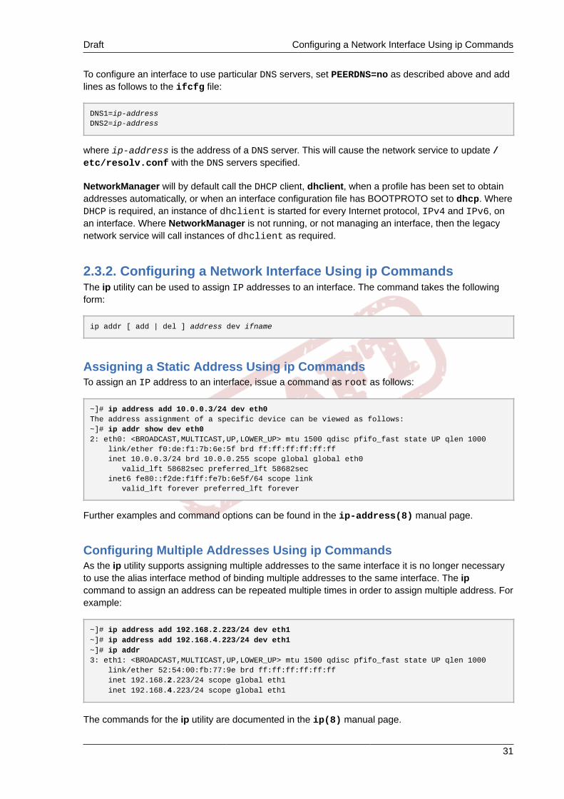
Draft Configuring a Network Interface Using ip Commands
31
To configure an interface to use particular DNS servers, set PEERDNS=no as described above and addlines as follows to the ifcfg file:
DNS1=ip-addressDNS2=ip-address
where ip-address is the address of a DNS server. This will cause the network service to update /etc/resolv.conf with the DNS servers specified.
NetworkManager will by default call the DHCP client, dhclient, when a profile has been set to obtainaddresses automatically, or when an interface configuration file has BOOTPROTO set to dhcp. WhereDHCP is required, an instance of dhclient is started for every Internet protocol, IPv4 and IPv6, onan interface. Where NetworkManager is not running, or not managing an interface, then the legacynetwork service will call instances of dhclient as required.
2.3.2. Configuring a Network Interface Using ip CommandsThe ip utility can be used to assign IP addresses to an interface. The command takes the followingform:
ip addr [ add | del ] address dev ifname
Assigning a Static Address Using ip CommandsTo assign an IP address to an interface, issue a command as root as follows:
~]# ip address add 10.0.0.3/24 dev eth0The address assignment of a specific device can be viewed as follows:~]# ip addr show dev eth02: eth0: <BROADCAST,MULTICAST,UP,LOWER_UP> mtu 1500 qdisc pfifo_fast state UP qlen 1000 link/ether f0:de:f1:7b:6e:5f brd ff:ff:ff:ff:ff:ff inet 10.0.0.3/24 brd 10.0.0.255 scope global global eth0 valid_lft 58682sec preferred_lft 58682sec inet6 fe80::f2de:f1ff:fe7b:6e5f/64 scope link valid_lft forever preferred_lft forever
Further examples and command options can be found in the ip-address(8) manual page.
Configuring Multiple Addresses Using ip CommandsAs the ip utility supports assigning multiple addresses to the same interface it is no longer necessaryto use the alias interface method of binding multiple addresses to the same interface. The ipcommand to assign an address can be repeated multiple times in order to assign multiple address. Forexample:
~]# ip address add 192.168.2.223/24 dev eth1~]# ip address add 192.168.4.223/24 dev eth1~]# ip addr3: eth1: <BROADCAST,MULTICAST,UP,LOWER_UP> mtu 1500 qdisc pfifo_fast state UP qlen 1000 link/ether 52:54:00:fb:77:9e brd ff:ff:ff:ff:ff:ff inet 192.168.2.223/24 scope global eth1 inet 192.168.4.223/24 scope global eth1
The commands for the ip utility are documented in the ip(8) manual page.

Chapter 2. Configure Networking Draft
32
Note
Note that ip commands given on the command line will not persist after a system restart.
2.3.3. Static Routes and the Default GatewayStatic routes are for traffic that must not, or should not, go through the default gateway. Routing isoften handled by devices on the network dedicated to routing (although any device can be configuredto perform routing). Therefore, it is often not necessary to configure static routes on Fedora servers orclients. Exceptions include traffic that must pass through an encrypted VPN tunnel or traffic that shouldtake a specific route for reasons of cost or security. The default gateway is for any and all traffic whichis not destined for the local network and for which no preferred route is specified in the routing table.The default gateway is traditionally a dedicated network router.
Configuring Static Routes Using the Command Line
If static routes are required, they can be added to the routing table by means of the ip route addcommand and removed using the ip route del command. The more frequently used ip routecommands take the following form:
ip route [ add | del | change | append | replace ] destination-address
See the ip-route(8) man page for more details on the options and formats.
Use the ip route command without options to display the IP routing table. For example:
~]$ ip routedefault via 192.168.122.1 dev eth1 proto static metric 1024192.168.122.0/24 dev eth1 proto kernel scope link src 192.168.122.107192.168.122.0/24 dev eth0 proto kernel scope link src 192.168.122.126
To add a static route to a host address, in other words to a single IP address, issue a command asroot:
ip route add 192.0.2.1 via 10.0.0.1 [dev ifname]
Where 192.0.2.1 is the IP address of the host in dotted decimal notation, 10.0.0.1 is the next hopaddress and ifname is the exit interface leading to the next hop.
To add a static route to a network, in other words to an IP address representing a range of IPaddresses, issue the following command as root:
ip route add 192.0.2.0/24 via 10.0.0.1 [dev ifname]
where 192.0.2.0 is the IP address of the destination network in dotted decimal notation and /24 isthe network prefix. The network prefix is the number of enabled bits in the subnet mask. This format ofnetwork address slash network prefix length is sometimes referred to as classless inter-domain routing(CIDR) notation.
Static route configuration can be stored per-interface in a /etc/sysconfig/network-scripts/route-interface file. For example, static routes for the eth0 interface would be stored in the /

Draft Configuring Static Routes in ifcfg files
33
etc/sysconfig/network-scripts/route-eth0 file. The route-interface file has twoformats: ip command arguments and network/netmask directives. These are described below.
See the ip-route(8) man page for more information on the ip route command.
Configuring The Default Gateway
The default gateway is determined by the network scripts which parse the /etc/sysconfig/network file first and then the network interface ifcfg files for interfaces that are “up”. The ifcfgfiles are parsed in numerically ascending order, and the last GATEWAY directive to be read is used tocompose a default route in the routing table.
The default route can thus be indicated by means of the GATEWAY directive, either globally or ininterface-specific configuration files. However, in Fedora the use of the global /etc/sysconfig/network file is deprecated, and specifying the gateway should now only be done in per-interfaceconfiguration files.
In dynamic network environments, where mobile hosts are managed by NetworkManager, gatewayinformation is likely to be interface specific and is best left to be assigned by DHCP. In special caseswhere it is necessary to influence NetworkManager's selection of the exit interface to be used toreach a gateway, make use of the DEFROUTE=no command in the ifcfg files for those interfaceswhich do not lead to the default gateway.
2.3.4. Configuring Static Routes in ifcfg filesStatic routes set using ip commands on the command line will be lost if the system is shutdownor restarted. To configure static routes to be persistent after a system restart, they must be placedin per-interface configuration files in the /etc/sysconfig/network-scripts/ directory. Thefile name should be of the format route-ifname. There are two types of commands to use inthe configuration files; ip commands as explained in Section 2.3.4.1, “Static Routes Using the IPCommand Arguments Format” and the Network/Netmask format as explained in Section 2.3.4.2,“Network/Netmask Directives Format”.
2.3.4.1. Static Routes Using the IP Command Arguments FormatIf required in a per-interface configuration file, for example /etc/sysconfig/network-scripts/route-eth0, define a route to a default gateway on the first line. This is only required if the gatewayis not set via DHCP and is not set globally in the /etc/sysconfig/network file:
default via 192.168.1.1 dev interface
where 192.168.1.1 is the IP address of the default gateway. The interface is the interface thatis connected to, or can reach, the default gateway. The dev option can be omitted, it is optional. Notethat this setting takes precedence over a setting in the /etc/sysconfig/network file.
If a route to a remote network is required, a static route can be specified as follows. Each line isparsed as an individual route:
10.10.10.0/24 via 192.168.1.1 [dev interface]
where 10.10.10.0/24 is the network address and prefix length of the remote or destination network.The address 192.168.1.1 is the IP address leading to the remote network. It is preferably the nexthop address but the address of the exit interface will work. The “next hop” means the remote end

Chapter 2. Configure Networking Draft
34
of a link, for example a gateway or router. The dev option can be used to specify the exit interfaceinterface but it is not required. Add as many static routes as required.
The following is an example of a route-interface file using the ip command arguments format.The default gateway is 192.168.0.1, interface eth0 and a leased line or WAN connection isavailable at 192.168.0.10. The two static routes are for reaching the 10.10.10.0/24 network andthe 172.16.1.10/32 host:
default via 192.168.0.1 dev eth010.10.10.0/24 via 192.168.0.10 dev eth0172.16.1.10/32 via 192.168.0.10 dev eth0
In the above example, packets going to the local 192.168.0.0/24 network will be directedout the interface attached to that network. Packets going to the 10.10.10.0/24 network and172.16.1.10/32 host will be directed to 192.168.0.10. Packets to unknown, remote, networkswill use the default gateway therefore static routes should only be configured for remote networks orhosts if the default route is not suitable. Remote in this context means any networks or hosts that arenot directly attached to the system.
Specifying an exit interface is optional. It can be useful if you want to force traffic out of a specificinterface. For example, in the case of a VPN, you can force traffic to a remote network to pass througha tun0 interface even when the interface is in a different subnet to the destination network.
Duplicate default gateways
If the default gateway is already assigned by DHCP and if the same gateway with the same metricis specified in a configuration file, an error during start-up, or when bringing up an interface, willoccur. The follow error message may be shown: "RTNETLINK answers: File exists". This errormay be ignored.
2.3.4.2. Network/Netmask Directives FormatYou can also use the network/netmask directives format for route-interface files. The following isa template for the network/netmask format, with instructions following afterwards:
ADDRESS0=10.10.10.0 NETMASK0=255.255.255.0 GATEWAY0=192.168.1.1
• ADDRESS0=10.10.10.0 is the network address of the remote network or host to be reached.
• NETMASK0=255.255.255.0 is the netmask for the network address defined withADDRESS0=10.10.10.0.
• GATEWAY0=192.168.1.1 is the default gateway, or an IP address that can be used to reachADDRESS0=10.10.10.0
The following is an example of a route-interface file using the network/netmask directivesformat. The default gateway is 192.168.0.1 but a leased line or WAN connection is available at192.168.0.10. The two static routes are for reaching the 10.10.10.0/24 and 172.16.1.0/24networks:
ADDRESS0=10.10.10.0NETMASK0=255.255.255.0
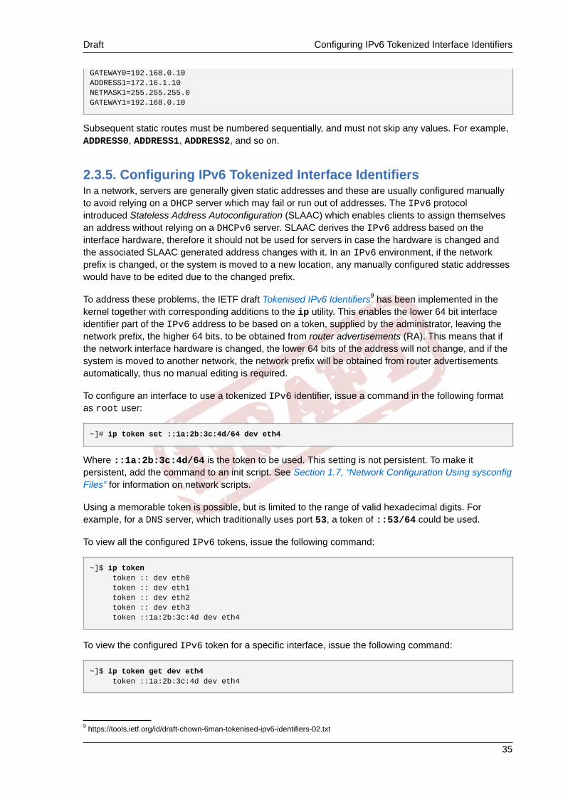
Draft Configuring IPv6 Tokenized Interface Identifiers
35
GATEWAY0=192.168.0.10ADDRESS1=172.16.1.10NETMASK1=255.255.255.0GATEWAY1=192.168.0.10
Subsequent static routes must be numbered sequentially, and must not skip any values. For example,ADDRESS0, ADDRESS1, ADDRESS2, and so on.
2.3.5. Configuring IPv6 Tokenized Interface IdentifiersIn a network, servers are generally given static addresses and these are usually configured manuallyto avoid relying on a DHCP server which may fail or run out of addresses. The IPv6 protocolintroduced Stateless Address Autoconfiguration (SLAAC) which enables clients to assign themselvesan address without relying on a DHCPv6 server. SLAAC derives the IPv6 address based on theinterface hardware, therefore it should not be used for servers in case the hardware is changed andthe associated SLAAC generated address changes with it. In an IPv6 environment, if the networkprefix is changed, or the system is moved to a new location, any manually configured static addresseswould have to be edited due to the changed prefix.
To address these problems, the IETF draft Tokenised IPv6 Identifiers9 has been implemented in thekernel together with corresponding additions to the ip utility. This enables the lower 64 bit interfaceidentifier part of the IPv6 address to be based on a token, supplied by the administrator, leaving thenetwork prefix, the higher 64 bits, to be obtained from router advertisements (RA). This means that ifthe network interface hardware is changed, the lower 64 bits of the address will not change, and if thesystem is moved to another network, the network prefix will be obtained from router advertisementsautomatically, thus no manual editing is required.
To configure an interface to use a tokenized IPv6 identifier, issue a command in the following formatas root user:
~]# ip token set ::1a:2b:3c:4d/64 dev eth4
Where ::1a:2b:3c:4d/64 is the token to be used. This setting is not persistent. To make itpersistent, add the command to an init script. See Section 1.7, “Network Configuration Using sysconfigFiles” for information on network scripts.
Using a memorable token is possible, but is limited to the range of valid hexadecimal digits. Forexample, for a DNS server, which traditionally uses port 53, a token of ::53/64 could be used.
To view all the configured IPv6 tokens, issue the following command:
~]$ ip token token :: dev eth0 token :: dev eth1 token :: dev eth2 token :: dev eth3 token ::1a:2b:3c:4d dev eth4
To view the configured IPv6 token for a specific interface, issue the following command:
~]$ ip token get dev eth4 token ::1a:2b:3c:4d dev eth4
9 https://tools.ietf.org/id/draft-chown-6man-tokenised-ipv6-identifiers-02.txt
Chapter 2. Configure Networking Draft
36
Note that adding a token to an interface will replace a previously allocated token, and in turn invalidatethe address derived from it. Supplying a new token causes a new address to be generated andapplied, but this process will leave any other addresses unchanged. In other words, a new tokenizedidentifier only replaces a previously existing tokenized identifier, not any other IP address.
Note
Take care not to add the same token to more than one system or interface. The duplicate addressdetection (DAD) mechanism will remove the duplicate address from the interface but it cannotchange the configuration. Once a token is set, it cannot be cleared or reset, except by rebootingthe machine.
2.4. Using the NetworkManager Command Line Tool, nmcliThe command‐line tool nmcli can be used by both users and scripts for controlling NetworkManager.The basic format of a command is as follows:
nmcli OPTIONS OBJECT { COMMAND | help }
where OBJECT can be one of general, networking, radio, connection, or device. The mostused options are: -t, --terse for use in scripts, the -p, --pretty option for users, and the -h, --help option. Command completion has been implemented for nmcli, so remember to pressTab whenever you are unsure of the command options available. See the nmcli(1) man page for acomplete list of the options and commands.
The nmcli tool has some built-in context-sensitive help. For example, issue the following twocommands and notice the difference:
~]$ nmcli helpUsage: nmcli [OPTIONS] OBJECT { COMMAND | help }
OPTIONS -t[erse] terse output -p[retty] pretty output -m[ode] tabular|multiline output mode -f[ields] <field1,field2,...>|all|common specify fields to output -e[scape] yes|no escape columns separators in values -n[ocheck] don't check nmcli and NetworkManager versions -a[sk] ask for missing parameters -w[ait] <seconds> set timeout waiting for finishing operations -v[ersion] show program version -h[elp] print this help
OBJECT g[eneral] NetworkManager's general status and operations n[etworking] overall networking control r[adio] NetworkManager radio switches c[onnection] NetworkManager's connections d[evice] devices managed by NetworkManager
~]$ nmcli general helpUsage: nmcli general { COMMAND | help }
COMMAND := { status | hostname | permissions | logging }
status

Draft Using the NetworkManager Command Line Tool, nmcli
37
hostname [<hostname>]
permissions
logging [level <log level>] [domains <log domains>]
In the second example above the help is related to the object general.
The nmcli-examples(5) man page has many useful examples. A brief selection is shown here:
To show the overall status of NetworkManager:
nmcli general status
To control NetworkManager logging:
nmcli general logging
To show all connections:
nmcli connection show
To show only currently active connections, add the -a, --active option as follows:
nmcli connection show --active
To show devices recognized by NetworkManager and their state:
nmcli device status
Commands can be shortened and some options omitted. For example the command:
nmcli connection modify id 'MyCafe' 802-11-wireless.mtu 1350
Can be reduced to the following command:
nmcli con mod MyCafe 802-11-wireless.mtu 1350
The id option can be omitted because the connection ID (name) is unambiguous for nmcli in thiscase. As you become familiar with the commands, further abbreviations can be made. For example:
nmcli connection add type ethernet
can be reduced to:
nmcli c a type eth
Note
Remember to use tab completion when in doubt.

Chapter 2. Configure Networking Draft
38
Starting and Stopping an Interface Using nmcliThe nmcli tool can be used to start and stop any network interface, including masters. For example:
nmcli con up id bond0nmcli con up id port0nmcli dev disconnect iface bond0nmcli dev disconnect iface eth0
Note
It is recommended to use nmcli dev disconnect iface iface-name rather than nmclicon down id id-string because disconnection places the interface into a “manual” mode,in which no automatic connection will be started until the user tells NetworkManager to start aconnection or until an external event like a carrier change, hibernate, or sleep, occurs.
The nmcli Interactive Connection EditorThe nmcli tool has an interactive connection editor. To use it, enter the following command:
~]$ nmcli con edit
You will be prompted to enter a valid connection type from the list displayed. After entering aconnection type you will be placed at the nmcli prompt. If you are familiar with the connection typesyou can add a valid connection type option to the nmcli con edit command and be taken straightto the nmcli prompt. The format is as follows for editing an existing connection profile:
nmcli con edit [id | uuid | path] ID
For adding and editing a new connection profile, the following format applies:
nmcli con edit [type new-connection-type] [con-name new-connection-name]
Type help at the nmcli prompt to see a list of valid commands. Use the describe command to get adescription of settings and their properties. The format is as follows:
describe setting.property
For example:
nmcli> describe team.config
2.4.1. Understanding the nmcli OptionsMany of the nmcli commands are self-explanatory, however a few command options are worth amoments study:
type — The connection type.Allowed values are: adsl, bond, bond-slave, bridge, bridge-slave, bluetooth, cdma,ethernet, generic, gsm, infiniband, olpc-mesh, pppoe, team, team-slave, vlan, vpn,wifi, wimax.
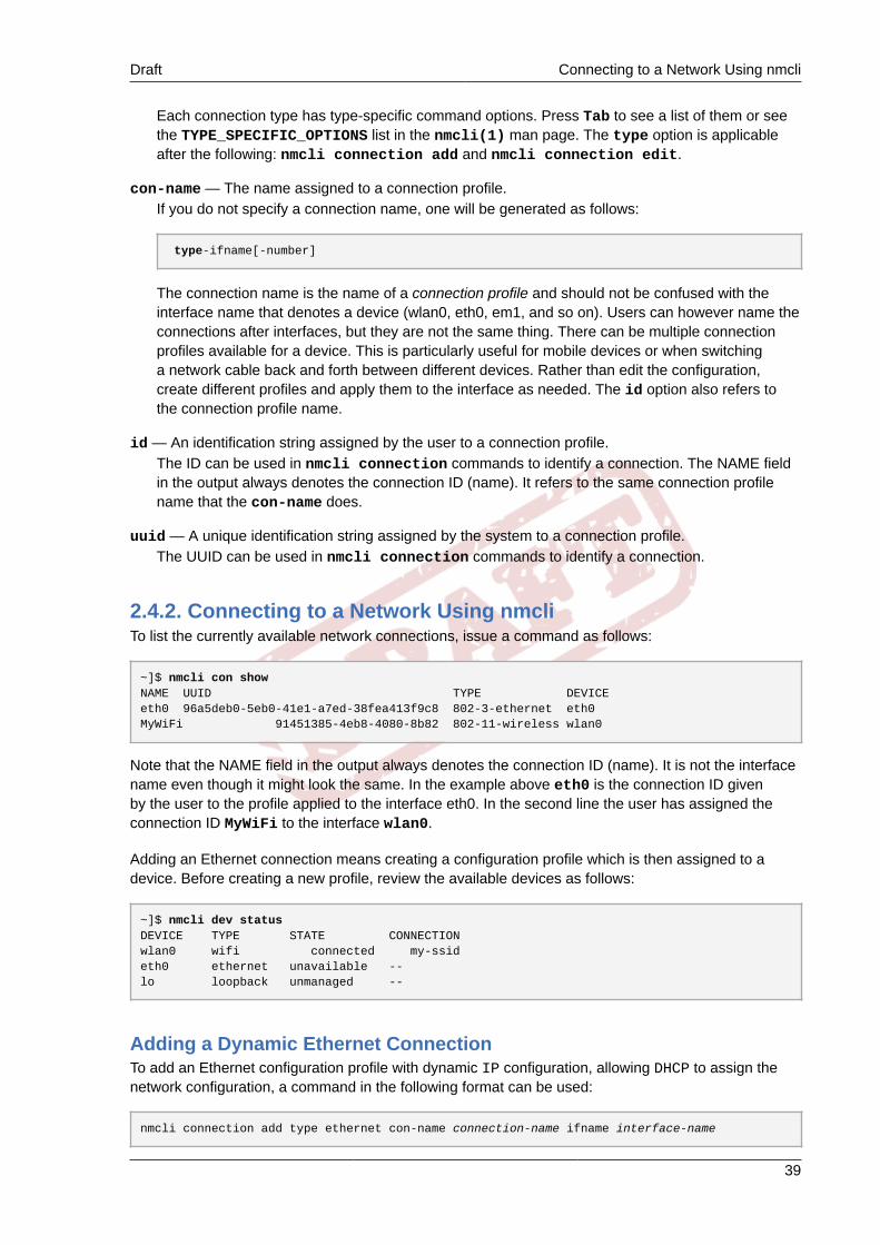
Draft Connecting to a Network Using nmcli
39
Each connection type has type-specific command options. Press Tab to see a list of them or seethe TYPE_SPECIFIC_OPTIONS list in the nmcli(1) man page. The type option is applicableafter the following: nmcli connection add and nmcli connection edit.
con-name — The name assigned to a connection profile.If you do not specify a connection name, one will be generated as follows:
type-ifname[-number]
The connection name is the name of a connection profile and should not be confused with theinterface name that denotes a device (wlan0, eth0, em1, and so on). Users can however name theconnections after interfaces, but they are not the same thing. There can be multiple connectionprofiles available for a device. This is particularly useful for mobile devices or when switchinga network cable back and forth between different devices. Rather than edit the configuration,create different profiles and apply them to the interface as needed. The id option also refers tothe connection profile name.
id — An identification string assigned by the user to a connection profile.The ID can be used in nmcli connection commands to identify a connection. The NAME fieldin the output always denotes the connection ID (name). It refers to the same connection profilename that the con-name does.
uuid — A unique identification string assigned by the system to a connection profile.The UUID can be used in nmcli connection commands to identify a connection.
2.4.2. Connecting to a Network Using nmcliTo list the currently available network connections, issue a command as follows:
~]$ nmcli con showNAME UUID TYPE DEVICE eth0 96a5deb0-5eb0-41e1-a7ed-38fea413f9c8 802-3-ethernet eth0MyWiFi 91451385-4eb8-4080-8b82 802-11-wireless wlan0
Note that the NAME field in the output always denotes the connection ID (name). It is not the interfacename even though it might look the same. In the example above eth0 is the connection ID givenby the user to the profile applied to the interface eth0. In the second line the user has assigned theconnection ID MyWiFi to the interface wlan0.
Adding an Ethernet connection means creating a configuration profile which is then assigned to adevice. Before creating a new profile, review the available devices as follows:
~]$ nmcli dev statusDEVICE TYPE STATE CONNECTIONwlan0 wifi connected my-ssideth0 ethernet unavailable --lo loopback unmanaged --
Adding a Dynamic Ethernet ConnectionTo add an Ethernet configuration profile with dynamic IP configuration, allowing DHCP to assign thenetwork configuration, a command in the following format can be used:
nmcli connection add type ethernet con-name connection-name ifname interface-name

Chapter 2. Configure Networking Draft
40
For example, to create a dynamic connection profile named my-office, issue a command as follows:
~]$ nmcli con add type ethernet con-name my-office ifname eth0Connection 'my-office' (0a053110-5361-412c-a4fb-6ff20877e9e4) successfully added.
NetworkManager will set its internal parameter connection.autoconnect to yes.NetworkManager will also write out settings to /etc/sysconfig/network-scripts/ifcfg-my-office where the ONBOOT directive will be set to yes.
Note that manual changes to the ifcfg file will not be noticed by NetworkManager until the interface isnext brought up. See Section 1.7, “Network Configuration Using sysconfig Files” for more informationon using configuration files.
To bring up the Ethernet connection, issue a command as follows:
~]$ nmcli con up my-officeConnection successfully activated (D-Bus active path: /org/freedesktop/NetworkManager/ActiveConnection/1)
Review the status of the devices and connections:
~]$ nmcli device statusDEVICE TYPE STATE CONNECTIONeth0 ethernet connected my-officelo loopback unmanaged --
To change the host name sent by a host to a DHCP server, modify the dhcp-hostname property asfollows:
~]$ nmcli con modify my-office my-office ipv4.dhcp-hostname host-name ipv6.dhcp-hostname host-name
To change the IPv4 client ID sent by a host to a DHCP server, modify the dhcp-client-id propertyas follows:
~]$ nmcli con modify my-office my-office ipv4.dhcp-client-id client-ID-string
There is no dhcp-client-id property for IPv6, dhclient creates an identifier for IPv6. See thedhclient(8) man page for details.
To ignore the DNS servers sent to a host by a DHCP server, modify the ignore-auto-dns property asfollows:
~]$ nmcli con modify my-office my-office ipv4.ignore-auto-dns yes ipv6.ignore-auto-dns yes
See the nm-settings(5) man page for more information on properties and their settings.
Example 2.1. Configuring a Dynamic Ethernet Connection Using the Interactive EditorTo configure a dynamic Ethernet connection using the interactive editor, issue commands asfollows:
~]$ nmcli con edit type ethernet con-name eth0
===| nmcli interactive connection editor |===

Draft Connecting to a Network Using nmcli
41
Adding a new '802-3-ethernet' connection
Type 'help' or '?' for available commands.Type 'describe [<setting>.<prop>]' for detailed property description.
You may edit the following settings: connection, 802-3-ethernet (ethernet), 802-1x, ipv4, ipv6, dcbnmcli> describe ipv4.method
=== [method] ===[NM property description]IPv4 configuration method. If 'auto' is specified then the appropriate automatic method (DHCP, PPP, etc) is used for the interface and most other properties can be left unset. If 'link-local' is specified, then a link-local address in the 169.254/16 range will be assigned to the interface. If 'manual' is specified, static IP addressing is used and at least one IP address must be given in the 'addresses' property. If 'shared' is specified (indicating that this connection will provide network access to other computers) then the interface is assigned an address in the 10.42.x.1/24 range and a DHCP and forwarding DNS server are started, and the interface is NAT-ed to the current default network connection. 'disabled' means IPv4 will not be used on this connection. This property must be set.
nmcli> set ipv4.method autonmcli> saveSaving the connection with 'autoconnect=yes'. That might result in an immediate activation of the connection.Do you still want to save? [yes] yesConnection 'eth0' (090b61f7-540f-4dd6-bf1f-a905831fc287) successfully saved.nmcli> quit~]$
The default action is to save the connection profile as persistent. If required, the profile can be heldin memory only, until the next restart, by means of the save temporary command.
Adding a Static Ethernet ConnectionTo add an Ethernet connection with static IPv4 configuration, a command in the following format canbe used:
nmcli connection add type ethernet con-name connection-name ifname interface-name ip4 address gw4 address
IPv6 address and gateway information can be added using the ip6 and gw6 options.
For example, a command to create a static Ethernet connection with only IPv4 address and gatewayis as follows:
~]$ nmcli con add type ethernet con-name test-lab ifname eth1 ip4 10.10.10.10/24 \gw4 10.10.10.254
Optionally, at the same time specify IPv6 address and gateway for the device as follows:
~]$ nmcli con add type ethernet con-name test-lab ifname eth1 ip4 10.10.10.10/24 \gw4 10.10.10.254 ip6 abbe::cafe gw6 2001:db8::1Connection 'test-lab' (05abfd5e-324e-4461-844e-8501ba704773) successfully added.
NetworkManager will set its internal parameter ipv4.method to manual andconnection.autoconnect to yes. NetworkManager will also write out settings to /etc/sysconfig/network-scripts/ifcfg-my-office where the corresponding BOOTPROTO willbe set to none and ONBOOT will be set to yes.

Chapter 2. Configure Networking Draft
42
Note that manual changes to the ifcfg file will not be noticed by NetworkManager until the interface isnext brought up. See Section 1.7, “Network Configuration Using sysconfig Files” for more informationon using configuration files.
To set two IPv4 DNS server addresses:
~]$ nmcli con mod test-lab ipv4.dns "8.8.8.8 8.8.4.4"
Note that this will replace any previously set DNS servers.
To set two IPv6 DNS server addresses:
~]$ nmcli con mod test-lab ipv6.dns "2001:4860:4860::8888 2001:4860:4860::8844"
Note that this will replace any previously set DNS servers.
Alternatively, to add additional DNS servers to any previously set, use the + prefix as follows:
~]$ nmcli con mod test-lab +ipv4.dns "8.8.8.8 8.8.4.4"
~]$ nmcli con mod test-lab +ipv6.dns "2001:4860:4860::8888 2001:4860:4860::8844"
To bring up the new Ethernet connection, issue a command as follows:
~]$ nmcli con up test-lab ifname eth1Connection successfully activated (D-Bus active path: /org/freedesktop/NetworkManager/ActiveConnection/2
Review the status of the devices and connections:
~]$ nmcli device statusDEVICE TYPE STATE CONNECTIONeth0 ethernet connected my-officeeth1 ethernet connected test-lablo loopback unmanaged --
To view detailed information about the newly configured connection, issue a command as follows:
~]$ nmcli -p con show test-lab=============================================================================== Connection profile details (test-lab)===============================================================================connection.id: test-labconnection.uuid: 05abfd5e-324e-4461-844e-8501ba704773connection.interface-name: eth1connection.type: 802-3-ethernetconnection.autoconnect: yesconnection.timestamp: 1410428968connection.read-only: noconnection.permissions: connection.zone: --connection.master: --connection.slave-type: --connection.secondaries: connection.gateway-ping-timeout: 0[output truncated]

Draft Connecting to a Network Using nmcli
43
The use of the -p, --pretty option adds a title banner and section breaks to the output.
Modifying a Static Ethernet ConnectionTo replace existing IP addresses, enter a command as follows:
~]$ nmcli con mod test-lab ipv4.addresses "192.168.112.112"
To add additional IP addresses, use the + prefix as follows:
~]$ nmcli con mod test-lab +ipv4.addresses "192.168.114.114"
Example 2.2. Configuring a Static Ethernet Connection Using the Interactive EditorTo configure a static Ethernet connection using the interactive editor, issue commands as follows:
~]$ nmcli con edit type ethernet con-name eth0
===| nmcli interactive connection editor |===
Adding a new '802-3-ethernet' connection
Type 'help' or '?' for available commands.Type 'describe [<setting>.<prop>]' for detailed property description.
You may edit the following settings: connection, 802-3-ethernet (ethernet), 802-1x, ipv4, ipv6, dcbnmcli> set ipv4.addresses 192.168.122.88/24Do you also want to set 'ipv4.method' to 'manual'? [yes]: yesnmcli>nmcli> save temporarySaving the connection with 'autoconnect=yes'. That might result in an immediate activation of the connection.Do you still want to save? [yes] nonmcli> saveSaving the connection with 'autoconnect=yes'. That might result in an immediate activation of the connection.Do you still want to save? [yes] yesConnection 'eth0' (704a5666-8cbd-4d89-b5f9-fa65a3dbc916) successfully saved.nmcli> quit~]$
The default action is to save the connection profile as persistent. If required, the profile can be heldin memory only, until the next restart, by means of the save temporary command.
Locking a Profile to a Specific DeviceTo lock a profile to a specific interface device, the commands used in the examples above include theinterface name. For example:
nmcli connection add type ethernet con-name connection-name ifname interface-name
To make a profile usable for all compatible Ethernet interfaces, issue a command as follows:
nmcli connection add type ethernet con-name connection-name ifname "*"
Note that you have to use the ifname argument even if you do not want to set a specific interface.Use the wildcard character * to specify that the profile can be used with any compatible device.
To lock a profile to a specific MAC address, use a command in the following format:

Chapter 2. Configure Networking Draft
44
nmcli connection add type ethernet con-name "connection-name" ifname "*" mac 00:00:5E:00:53:00
Adding a Wi-Fi ConnectionTo view the available Wi-Fi access points, issue a command as follows:
~]$ nmcli dev wifi list SSID MODE CHAN RATE SIGNAL BARS SECURITY FedoraTest Infra 11 54 MB/s 98 #▄#█ WPA1 Red Hat Guest Infra 6 54 MB/s 97 #▄#█ WPA2 Red Hat Infra 6 54 MB/s 77 #▄#_ WPA2 802.1X* Red Hat Infra 40 54 MB/s 66 #▄#_ WPA2 802.1X VoIP Infra 1 54 MB/s 32 #▄__ WEP MyCafe Infra 11 54 MB/s 39 #▄__ WPA2
To create a Wi-Fi connection profile with static IP configuration, but allowing automatic DNS addressassignment, issue a command as follows:
~]$ nmcli con add con-name MyCafe ifname wlan0 type wifi ssid MyCafe \ip4 192.168.100.101/24 gw4 192.168.100.1
To set a WPA2 password, for example “caffeine”, issue commands as follows:
~]$ nmcli con modify MyCafe wifi-sec.key-mgmt wpa-psk~]$ nmcli con modify MyCafe wifi-sec.psk caffeine
To change Wi-Fi state, issue a command in the following format:
~]$ nmcli radio wifi [on | off ]
Changing a Specific PropertyTo check a specific property, for example mtu, issue a command as follows:
~]$ nmcli connection show id 'MyCafe' | grep mtu802-11-wireless.mtu: auto
To change the property of a setting, issue a command as follows:
~]$ nmcli connection modify id 'MyCafe' 802-11-wireless.mtu 1350
To verify the change, issue a command as follows:
~]$ nmcli connection show id 'MyCafe' | grep mtu802-11-wireless.mtu: 1350
Note that NetworkManager refers to parameters such as 802-3-ethernet and 802-11-wirelessas the setting, and mtu as a property of the setting. See the nm-settings(5) man page for moreinformation on properties and their settings.
2.4.3. Configuring Static Routes Using nmcliStatic routes can only be set per-interface, not globally, using the nmcli tool. The command line or theinteractive editor mode can be be used.

Draft Additional Resources
45
Example 2.3. Configuring Static Routes Using nmcliTo configure a static route for an existing Ethernet connection using the command line, enter acommand as follows:
~]# nmcli connection modify eth0 +ipv4.routes 192.168.122.0/24 ipv4.gateway 10.10.10.1
This will direct traffic for the 192.168.122.0/24 subnet to the gateway at 10.10.10.1
Example 2.4. Configuring Static Routes Using nmcli EditorTo configure a static route for an Ethernet connection using the interactive editor, issue commandsas follows:
~]$ nmcli con edit type ethernet con-name eth0
===| nmcli interactive connection editor |===
Adding a new '802-3-ethernet' connection
Type 'help' or '?' for available commands.Type 'describe [<setting>.<prop>]' for detailed property description.
You may edit the following settings: connection, 802-3-ethernet (ethernet), 802-1x, ipv4, ipv6, dcbnmcli> set ipv4.routes 192.168.122.0/24 10.10.10.1nmcli>nmcli> save persistentSaving the connection with 'autoconnect=yes'. That might result in an immediate activation of the connection.Do you still want to save? [yes] yesConnection 'eth0' (704a5666-8cbd-4d89-b5f9-fa65a3dbc916) successfully saved.nmcli> quit~]$
2.5. Additional ResourcesThe following sources of information provide additional resources relevant to this chapter.
2.5.1. Installed Documentation• ip(8) man page — Describes the ip utility's command syntax.
• nmcli(1) man page — Describes NetworkManager's command‐line tool.
• nmcli-examples(5) man page — Gives examples of nmcli commands.
• nm-settings(5) man page — Describes NetworkManager properties and their settings.
2.5.2. Online DocumentationRFC 151810 — Classless Inter-Domain Routing (CIDR)
Describes the CIDR Address Assignment and Aggregation Strategy, including variable-lengthsubnetting.
10 http://www.rfc-editor.org/info/rfc1518

Chapter 2. Configure Networking Draft
46
RFC 191811 — Address Allocation for Private InternetsDescribes the range of IPv4 addresses reserved for private use.
RFC 333012 — Special-Use IPv4 AddressesDescribes the global and other specialized IPv4 address blocks that have been assigned by theInternet Assigned Numbers Authority (IANA).
11 http://www.rfc-editor.org/info/rfc191812 http://www.rfc-editor.org/info/rfc3330

Draft Chapter 3. Draft
47
Configure Host Names
3.1. Understanding Host NamesThere are three classes of hostname: static, pretty, and transient.
The “static” host name is the traditional hostname, which can be chosen by the user, and is storedin the /etc/hostname file. The “transient” hostname is a dynamic host name maintained by thekernel. It is initialized to the static host name by default, whose value defaults to “localhost”. It canbe changed by DHCP or mDNS at runtime. The “pretty” hostname is a free-form UTF8 host name forpresentation to the user.
Note
A host name can be a free-form string up to 64 characters in length. However, Red Hatrecommends that both static and transient names match the fully-qualified domain name (FQDN)used for the machine in DNS, such as host.example.com. It is also recommended that thestatic and transient names consists only of 7 bit ASCII lower-case characters, no spaces ordots, and limits itself to the format allowed for DNS domain name labels, even though this is nota strict requirement. Older specifications do not permit the underscore, and so their use is notrecommended.
The hostnamectl tool will enforce the following: Static and transient host names to consistof a-z, A-Z, 0-9, “-”, “_” and “.” only, to not begin or end in a dot, and to not have two dotsimmediately following each other. The size limit of 64 characters is enforced.
3.1.1. Recommended Naming PracticesThe Internet Corporation for Assigned Names and Numbers (ICANN) sometimes adds previouslyunregistered Top-Level Domains (such as .yourcompany) to the public register. Therefore, Red Hatstrongly recommends that you do not use a domain name that is not delegated to you, even on aprivate network, as this can result in a domain name that resolves differently depending on networkconfiguration. As a result, network resources can become unavailable. Using domain names that arenot delegated to you also makes DNSSEC more difficult to deploy and maintain, as domain namecollisions require manual configuration to enable DNSSEC validation. See the ICANN FAQ on domainname collision1 for more information on this issue.
3.2. Configuring Host Names Using hostnamectlThe hostnamectl tool is provided for administering the three separate classes of host names in useon a given system.
3.2.1. View All the Host NamesTo view all the current host names, enter the following command:
~]$ hostnamectl status
1 http://www.icann.org/en/help/name-collision/faqs

Chapter 3. Configure Host Names Draft
48
The status option is implied by default if no option is given.
3.2.2. Set All the Host NamesTo set all the host names on a system, enter the following command as root:
~]# hostnamectl set-hostname name
This will alter the pretty, static, and transient host names alike. The static and transient host names willbe simplified forms of the pretty host name. Spaces will be replaced with “-” and special characterswill be removed.
3.2.3. Set a Particular Host NameTo set a particular host name, enter the following command as root with the relevant option:
~]# hostnamectl set-hostname name [option...]
Where option is one or more of: --pretty, --static, and --transient.
If the --static or --transient options are used together with the --pretty option, the static andtransient host names will be simplified forms of the pretty host name. Spaces will be replaced with “-”and special characters will be removed. If the --pretty option is not given, no simplification takesplace.
When setting a pretty host name, remember to use the appropriate quotation marks if the host namecontains spaces or a single quotation mark. For example:
~]# hostnamectl set-hostname "Stephen's notebook" --pretty
3.2.4. Clear a Particular Host NameTo clear a particular host name and allow it to revert to the default, enter the following command asroot with the relevant option:
~]# hostnamectl set-hostname "" [option...]
Where "" is a quoted empty string and where option is one or more of: --pretty, --static, and--transient.
3.2.5. Changing Host Names RemotelyTo execute a hostnamectl command on a remote system, use the -H, --host option as follows:
~]# hostnamectl set-hostname -H [username]@hostname
Where hostname is the remote host you want to configure. The username is optional. Thehostnamectl tool will use SSH to connect to the remote system.
3.3. Configuring Host Names Using nmcliThe NetworkManager tool nmcli can be used to query and set the static host name in the /etc/hostname file. Note that at time of writing, changing the host name in this way will not be noticed byhostnamectl.

Draft Additional Resources
49
To query the static host name, issue the following command:
~]$ nmcli general hostname
To set the static host name to my-server, issue the following command as root:
~]# nmcli general hostname my-server
To force hostnamectl to notice the change in the static host name, restart hostnamed as root:
~]# systemctl restart systemd-hostnamed
3.4. Additional ResourcesThe following sources of information provide additional resources regarding hostnamectl.
3.4.1. Installed Documentation• hostnamectl(1) man page — Describes hostnamectl including the commands and command
options.
• hostname(1) man page — Contains an explanation of the hostname and domainnamecommands.
• hostname(5) man page — Contains an explanation of the host name file, its contents, and use.
• hostname(7) man page — Contains an explanation of host name resolution.
• machine-info(5) man page — Describes the local machine information file and the environmentvariables it contains.
• machine-id(5) man page — Describes the local machine ID configuration file.
• systemd-hostnamed.service(8) man page — Describes the systemd-hostnamed systemservice used by hostnamectl.
3.4.2. Online Documentationhttp://www.freedesktop.org/wiki/Software/systemd/hostnamed
Information on systemd-hostnamed.

50

Draft Chapter 4. Draft
51
Configure Network BondingFedora allows administrators to bind multiple network interfaces together into a single, bonded,channel. Channel bonding enables two or more network interfaces to act as one, simultaneouslyincreasing the bandwidth and providing redundancy.
Warning
The use of direct cable connections without network switches is not supported for bonding. Thefailover mechanisms described here will not work as expected without the presence of networkswitches.
Note
The active-backup, balance-tlb and balance-alb modes do not require any specific configurationof the switch. Other bonding modes require configuring the switch to aggregate the links. Forexample, a Cisco switch requires EtherChannel for Modes 0, 2, and 3, but for Mode 4 LACP andEtherChannel are required. See the documentation supplied with your switch and see https://www.kernel.org/doc/Documentation/networking/bonding.txt.
4.1. Understanding the Default Behavior of Master andSlave InterfacesWhen controlling bonded slave interfaces using the NetworkManager daemon, and especially whenfault finding, keep the following in mind:1. Starting the master interface does not automatically start the slave interfaces.
2. Starting a slave interface always starts the master interface.
3. Stopping the master interface also stops the slave interfaces.
4. A master without slaves can start static IP connections.
5. A master without slaves waits for slaves when starting DHCP connections.
6. A master with a DHCP connection waiting for slaves completes when a slave with a carrier isadded.
7. A master with a DHCP connection waiting for slaves continues waiting when a slave without acarrier is added.
4.2. Creating a Bond Connection Using a GUIYou can use the GNOME control-center utility to direct NetworkManager to create a Bond from twoor more Wired or InfiniBand connections. It is not necessary to create the connections to be bondedfirst. They can be configured as part of the process to configure the bond. You must have the MACaddresses of the interfaces available in order to complete the configuration process.

Chapter 4. Configure Network Bonding Draft
52
4.2.1. Establishing a Bond Connection
Procedure 4.1. Adding a New Bond ConnectionYou can configure a Bond connection by opening the Network window, clicking the plus symbol, andselecting Bond from the list.
1. Press the Super key to enter the Activities Overview, type control network and then pressEnter. The Network settings tool appears.
2. Click the plus symbol to open the selection list. Select Bond. The Editing Bond connection 1window appears.
3. On the Bond tab, click Add and select the type of interface you want to use with the bondconnection. Click the Create button. Note that the dialog to select the slave type only comes upwhen you create the first slave; after that, it will automatically use that same type for all furtherslaves.
4. The Editing bond0 slave 1 window appears. Use the Device MAC address drop-down menu toselect the MAC address of the interface to be bonded. The first slave's MAC address will be usedas the MAC address for the bond interface. If required, enter a clone MAC address to be used asthe bond's MAC address. Click the Save button.
5. The name of the bonded slave appears in the Bonded connections window. Click the Addbutton to add further slave connections.
6. Review and confirm the settings and then click the Save button.
7. Edit the bond-specific settings by referring to Section 4.2.1.1, “Configuring the Bond Tab” below.
Procedure 4.2. Editing an Existing Bond ConnectionFollow these steps to edit an existing bond connection.
1. Press the Super key to enter the Activities Overview, type control network and then pressEnter. The Network settings tool appears.
2. Select the connection you want to edit and click the Options button.
3. Select the General tab.
4. Configure the connection name, auto-connect behavior, and availability settings.
Five settings in the Editing dialog are common to all connection types, see the General tab:
• Connection name — Enter a descriptive name for your network connection. This name will beused to list this connection in the menu of the Network window.
• Automatically connect to this network when it is available — Select this box if you wantNetworkManager to auto-connect to this connection when it is available. See Section 2.2.3,“Connecting to a Network Automatically” for more information.
• All users may connect to this network — Select this box to create a connection available toall users on the system. Changing this setting may require root privileges. See Section 2.2.4,“System-wide and Private Connection Profiles” for details.
• Automatically connect to VPN when using this connection — Select this box if you wantNetworkManager to auto-connect to a VPN connection when it is available. Select the VPNfrom the drop-down menu.

Draft Establishing a Bond Connection
53
• Firewall Zone — Select the firewall zone from the drop-down menu.
5. Edit the bond-specific settings by referring to Section 4.2.1.1, “Configuring the Bond Tab” below.
Saving Your New (or Modified) Connection and Making FurtherConfigurationsOnce you have finished editing your bond connection, click the Save button to save your customizedconfiguration. If the profile was in use while being edited, power cycle the connection to makeNetworkManager apply the changes. If the profile is OFF, set it to ON. See Section 2.2.1, “Connectingto a Network Using a GUI” for information on using your new or altered connection.
You can further configure an existing connection by selecting it in the Network window and clickingOptions to return to the Editing dialog.
Then, to configure:
• IPv4 settings for the connection, click the IPv4 Settings tab and proceed to Section 2.2.10.4,“Configuring IPv4 Settings”; or,
• IPv6 settings for the connection, click the IPv6 Settings tab and proceed to Section 2.2.10.5,“Configuring IPv6 Settings”.
4.2.1.1. Configuring the Bond TabIf you have already added a new bond connection (refer to Procedure 4.1, “Adding a New BondConnection” for instructions), you can edit the Bond tab to set the load sharing mode and the type oflink monitoring to use to detect failures of a slave connection.
ModeThe mode that is used to share traffic over the slave connections which make up the bond. Thedefault is Round-robin. Other load sharing modes, such as 802.3ad, can be selected by meansof the drop-down list.
Link MonitoringThe method of monitoring the slaves ability to carry network traffic.
The following modes of load sharing are selectable from the Mode drop-down list:
Round-robinSets a round-robin policy for fault tolerance and load balancing. Transmissions are received andsent out sequentially on each bonded slave interface beginning with the first one available. Thismode might not work behind a bridge with virtual machines without additional switch configuration.
Active backupSets an active-backup policy for fault tolerance. Transmissions are received and sent out via thefirst available bonded slave interface. Another bonded slave interface is only used if the activebonded slave interface fails. Note that this is the only mode available for bonds of InfiniBanddevices.
XORSets an XOR (exclusive-or) policy. Transmissions are based on the selected hash policy. Thedefault is to derive a hash by XOR of the source and destination MAC addresses multiplied bythe modulo of the number of slave interfaces. In this mode traffic destined for specific peers willalways be sent over the same interface. As the destination is determined by the MAC addresses

Chapter 4. Configure Network Bonding Draft
54
this method works best for traffic to peers on the same link or local network. If traffic has to passthrough a single router then this mode of traffic balancing will be suboptimal.
BroadcastSets a broadcast policy for fault tolerance. All transmissions are sent on all slave interfaces. Thismode might not work behind a bridge with virtual machines without additional switch configuration.
802.3adSets an IEEE 802.3ad dynamic link aggregation policy. Creates aggregation groups thatshare the same speed and duplex settings. Transmits and receives on all slaves in the activeaggregator. Requires a network switch that is 802.3ad compliant.
Adaptive transmit load balancingSets an adaptive Transmit Load Balancing (TLB) policy for fault tolerance and load balancing. Theoutgoing traffic is distributed according to the current load on each slave interface. Incoming trafficis received by the current slave. If the receiving slave fails, another slave takes over the MACaddress of the failed slave. This mode is only suitable for local addresses known to the kernelbonding module and therefore cannot be used behind a bridge with virtual machines.
Adaptive load balancingSets an Adaptive Load Balancing (ALB) policy for fault tolerance and load balancing. Includestransmit and receive load balancing for IPv4 traffic. Receive load balancing is achieved throughARP negotiation. This mode is only suitable for local addresses known to the kernel bondingmodule and therefore cannot be used behind a bridge with virtual machines.
The following types of link monitoring can be selected from the Link Monitoring drop-down list. It is agood idea to test which channel bonding module parameters work best for your bonded interfaces.
MII (Media Independent Interface)The state of the carrier wave of the interface is monitored. This can be done by querying thedriver, by querying MII registers directly, or by using ethtool to query the device. Three options areavailable:
Monitoring FrequencyThe time interval, in milliseconds, between querying the driver or MII registers.
Link up delayThe time in milliseconds to wait before attempting to use a link that has been reported as up.This delay can be used if some gratuitous ARP requests are lost in the period immediatelyfollowing the link being reported as “up”. This can happen during switch initialization forexample.
Link down delayThe time in milliseconds to wait before changing to another link when a previously active linkhas been reported as “down”. This delay can be used if an attached switch takes a relativelylong time to change to backup mode.
ARPThe address resolution protocol (ARP) is used to probe one or more peers to determine how wellthe link-layer connections are working. It is dependent on the device driver providing the transmitstart time and the last receive time.
Two options are available:
Monitoring FrequencyThe time interval, in milliseconds, between sending ARP requests.

Draft Using the Command Line Interface (CLI)
55
ARP targetsA comma separated list of IP addresses to send ARP requests to.
4.3. Using the Command Line Interface (CLI)A bond is created using the bonding kernel module and a special network interface called a channelbonding interface.
4.3.1. Check if Bonding Kernel Module is InstalledIn Fedora, the bonding module is not loaded by default. You can load the module by issuing thefollowing command as root:
~]# modprobe --first-time bonding
This activation will not persist across system restarts. See the Fedora 23 System Administrator'sGuide for an explanation of persistent module loading. Note that given a correct configuration file usingthe BONDING_OPTS directive, the bonding module will be loaded as required and therefore does notneed to be loaded separately.
To display information about the module, issue the following command:
~]$ modinfo bonding
See the modprobe(8) man page for more command options.
4.3.2. Create a Channel Bonding InterfaceTo create a channel bonding interface, create a file in the /etc/sysconfig/network-scripts/directory called ifcfg-bondN, replacing N with the number for the interface, such as 0.
The contents of the file can be based on a configuration file for whatever type of interface isgetting bonded, such as an Ethernet interface. The essential differences are that the DEVICEdirective is bondN, replacing N with the number for the interface, and TYPE=Bond. In addition, setBONDING_MASTER=yes.
Example 4.1. Example ifcfg-bond0 Interface Configuration FileAn example of a channel bonding interface.
DEVICE=bond0NAME=bond0TYPE=BondBONDING_MASTER=yesIPADDR=192.168.1.1PREFIX=24ONBOOT=yesBOOTPROTO=noneBONDING_OPTS="bonding parameters separated by spaces"
The NAME directive is useful for naming the connection profile in NetworkManager. ONBOOTsays whether the profile should be started when booting (or more generally, when auto-connecting adevice).

Chapter 4. Configure Network Bonding Draft
56
Put all Bonding Module Parameters in ifcfg-bondN Files
Parameters for the bonding kernel module must be specified as a space-separated list in theBONDING_OPTS="bonding parameters" directive in the ifcfg-bondN interface file. Donot specify options for the bonding device in /etc/modprobe.d/bonding.conf, or in thedeprecated /etc/modprobe.conf file.
The max_bonds parameter is not interface specific and should not be set when using ifcfg-bondN files with the BONDING_OPTS directive as this directive will cause the network scripts tocreate the bond interfaces as required.
For further instructions and advice on configuring the bonding module and to view the list ofbonding parameters, see Section 4.4, “Using Channel Bonding”.
4.3.3. Creating SLAVE InterfacesThe channel bonding interface is the “master” and the interfaces to be bonded are referred to as the“slaves”. After the channel bonding interface is created, the network interfaces to be bound togethermust be configured by adding the MASTER and SLAVE directives to the configuration files of theslaves. The configuration files for each of the slave interfaces can be nearly identical.
Example 4.2. Example Slave Interface Configuration FileFor example, if two Ethernet interfaces are being channel bonded, eth0 and eth1, they can bothlook like the following example:
DEVICE=ethNNAME=bond0-slaveTYPE=EthernetBOOTPROTO=noneONBOOT=yesMASTER=bond0SLAVE=yes
In this example, replace N with the numerical value for the interface. Note that if more than oneprofile or configuration file exists with ONBOOT=yes for an interface, they may race with each otherand a plain TYPE=Ethernet profile may be activated instead of a bond slave.
4.3.4. Activating a Channel BondTo activate a bond, bring up all the slaves. As root, issue the following commands:
~]# ifup ifcfg-eth0Connection successfully activated (D-Bus active path: /org/freedesktop/NetworkManager/ActiveConnection/7)
~]# ifup ifcfg-eth1Connection successfully activated (D-Bus active path: /org/freedesktop/NetworkManager/ActiveConnection/8)
Note that if editing interface files for interfaces which are currently “up”, set them down first as follows:
ifdown ethN

Draft Creating Multiple Bonds
57
Then when complete, bring up all the slaves, which will bring up the bond (provided it was not set“down”).
To make NetworkManager aware of the changes, issue a command for every changed interface asroot:
~]# nmcli con load /etc/sysconfig/network-scripts/ifcfg-device
Alternatively, to reload all interfaces:
~]# nmcli con reload
The default behavior is for NetworkManager not to be aware of the changes and to continueusing the old configuration data. This is set by the monitor-connection-files option inthe NetworkManager.conf file. See the NetworkManager.conf(5) manual page for moreinformation.
To view the status of the bond interface, issue the following command:
~]# ip link show1: lo: <LOOPBACK,UP,LOWER_UP> mtu 65536 qdisc noqueue state UNKNOWN mode DEFAULT link/loopback 00:00:00:00:00:00 brd 00:00:00:00:00:002: eth0: <BROADCAST,MULTICAST,SLAVE,UP,LOWER_UP> mtu 1500 qdisc pfifo_fast master bond0 state UP mode DEFAULT qlen 1000 link/ether 52:54:00:e9:ce:d2 brd ff:ff:ff:ff:ff:ff3: eth1: <BROADCAST,MULTICAST,SLAVE,UP,LOWER_UP> mtu 1500 qdisc pfifo_fast master bond0 state UP mode DEFAULT qlen 1000 link/ether 52:54:00:38:a6:4c brd ff:ff:ff:ff:ff:ff4: bond0: <BROADCAST,MULTICAST,MASTER,UP,LOWER_UP> mtu 1500 qdisc noqueue state UP mode DEFAULT link/ether 52:54:00:38:a6:4c brd ff:ff:ff:ff:ff:ff
4.3.5. Creating Multiple BondsIn Fedora 23, for each bond a channel bonding interface is created including the BONDING_OPTSdirective. This configuration method is used so that multiple bonding devices can have differentconfigurations. To create multiple channel bonding interfaces, proceed as follows:• Create multiple ifcfg-bondN files with the BONDING_OPTS directive; this directive will cause the
network scripts to create the bond interfaces as required.
• Create, or edit existing, interface configuration files to be bonded and include the SLAVE directive.
• Assign the interfaces to be bonded, the slave interfaces, to the channel bonding interfaces bymeans of the MASTER directive.
Example 4.3. Example multiple ifcfg-bondN interface configuration filesThe following is an example of a channel bonding interface configuration file:
DEVICE=bondNNAME=bondNTYPE=BondBONDING_MASTER=yesIPADDR=192.168.1.1PREFIX=24ONBOOT=yesBOOTPROTO=noneBONDING_OPTS="bonding parameters separated by spaces"

Chapter 4. Configure Network Bonding Draft
58
In this example, replace N with the number for the bond interface. For example, to create two bondscreate two configuration files, ifcfg-bond0 and ifcfg-bond1, with appropriate IP addresses.
Create the interfaces to be bonded as per Example 4.2, “Example Slave Interface Configuration File”and assign them to the bond interfaces as required using the MASTER=bondN directive. For example,continuing on from the example above, if two interfaces per bond are required, then for two bondscreate four interface configuration files and assign the first two using MASTER=bond0 and the next twousing MASTER=bond1.
4.3.6. Configuring a VLAN over a BondThis section will show configuring a VLAN over a bond consisting of two Ethernet links between aserver and an Ethernet switch. The switch has a second bond to another server. Only the configurationfor the first server will be shown as the other is essentially the same apart from the IP addresses.
Warning
The use of direct cable connections without network switches is not supported for bonding. Thefailover mechanisms described here will not work as expected without the presence of networkswitches.
Note
The active-backup, balance-tlb and balance-alb modes do not require any specific configurationof the switch. Other bonding modes require configuring the switch to aggregate the links. Forexample, a Cisco switch requires EtherChannel for Modes 0, 2, and 3, but for Mode 4 LACP andEtherChannel are required. See the documentation supplied with your switch and see https://www.kernel.org/doc/Documentation/networking/bonding.txt.
Check the available interfaces on the server:
~]$ ip addr1: lo: <LOOPBACK,UP,LOWER_UP> mtu 65536 qdisc noqueue state UNKNOWN link/loopback 00:00:00:00:00:00 brd 00:00:00:00:00:00 inet 127.0.0.1/8 scope host lo inet6 ::1/128 scope host valid_lft forever preferred_lft forever2: eth0: <BROADCAST,MULTICAST> mtu 1500 qdisc pfifo_fast state DOWN qlen 1000 link/ether 52:54:00:19:28:fe brd ff:ff:ff:ff:ff:ff3: eth1: <BROADCAST,MULTICAST> mtu 1500 qdisc pfifo_fast state DOWN qlen 1000 link/ether 52:54:00:f6:63:9a brd ff:ff:ff:ff:ff:ff
Procedure 4.3. Configuring the Interfaces on the Server1. Configure a slave interface using eth0:
~]# vi /etc/sysconfig/network-scripts/ifcfg-eth0NAME=bond0-slave0DEVICE=eth0 TYPE=Ethernet

Draft Configuring a VLAN over a Bond
59
BOOTPROTO=noneONBOOT=yesMASTER=bond0SLAVE=yes
The use of the NAME directive is optional. It is for display by a GUI interface, such as nm-connection-editor.
2. Configure a slave interface using eth1:
~]# vi /etc/sysconfig/network-scripts/ifcfg-eth1NAME=bond0-slave1DEVICE=eth1TYPE=EthernetBOOTPROTO=noneONBOOT=yesMASTER=bond0SLAVE=yes
The use of the NAME directive is optional. It is for display by a GUI interface, such as nm-connection-editor.
3. Configure a channel bonding interface ifcfg-bond0:
~]# vi /etc/sysconfig/network-scripts/ifcfg-bond0NAME=bond0DEVICE=bond0BONDING_MASTER=yesTYPE=BondIPADDR=192.168.100.100NETMASK=255.255.255.0ONBOOT=yesBOOTPROTO=noneBONDING_OPTS="mode=active-backup miimon=100"
The use of the NAME directive is optional. It is for display by a GUI interface, such as nm-connection-editor. In this example MII is used for link monitoring, see the Section 4.4.1,“Bonding Module Directives” section for more information on link monitoring.
4. Check the status of the interfaces on the server:
~]$ ip addr1: lo: <LOOPBACK,UP,LOWER_UP> mtu 65536 qdisc noqueue state UNKNOWN link/loopback 00:00:00:00:00:00 brd 00:00:00:00:00:00 inet 127.0.0.1/8 scope host lo inet6 ::1/128 scope host valid_lft forever preferred_lft forever2: eth0: <BROADCAST,MULTICAST,UP,LOWER_UP> mtu 1500 qdisc pfifo_fast state UP qlen 1000 link/ether 52:54:00:19:28:fe brd ff:ff:ff:ff:ff:ff inet6 fe80::5054:ff:fe19:28fe/64 scope link valid_lft forever preferred_lft forever3: eth1: <BROADCAST,MULTICAST,UP,LOWER_UP> mtu 1500 qdisc pfifo_fast state UP qlen 1000 link/ether 52:54:00:f6:63:9a brd ff:ff:ff:ff:ff:ff inet6 fe80::5054:ff:fef6:639a/64 scope link valid_lft forever preferred_lft forever
Procedure 4.4. Resolving Conflicts with InterfacesThe interfaces configured as slaves should not have IP addresses assigned to them apart from theIPv6 link-local addresses (starting fe80). If you have an unexpected IP address, then there may beanother configuration file with ONBOOT set to yes.

Chapter 4. Configure Network Bonding Draft
60
1. If this occurs, issue the following command to list all ifcfg files that may be causing a conflict:
~]$ grep -r "ONBOOT=yes" /etc/sysconfig/network-scripts/ | cut -f1 -d":" | xargs grep -E "IPADDR|SLAVE"/etc/sysconfig/network-scripts/ifcfg-lo:IPADDR=127.0.0.1
The above shows the expected result on a new installation. Any file having both the ONBOOTdirective as well as the IPADDR or SLAVE directive will be displayed. For example, if the ifcfg-eth1 file was incorrectly configured, the display might look similar to the following:
~]# grep -r "ONBOOT=yes" /etc/sysconfig/network-scripts/ | cut -f1 -d":" | xargs grep -E "IPADDR|SLAVE"/etc/sysconfig/network-scripts/ifcfg-lo:IPADDR=127.0.0.1/etc/sysconfig/network-scripts/ifcfg-eth1:SLAVE=yes/etc/sysconfig/network-scripts/ifcfg-eth1:IPADDR=192.168.55.55
2. Any other configuration files found should be moved to a different directory for backup, orassigned to a different interface by means of the HWADDR directive. After resolving any conflictset the interfaces “down” and “up” again or restart the network service as root:
~]# systemctl restart networkShutting down interface bond0: [ OK ]Shutting down loopback interface: [ OK ]Bringing up loopback interface: [ OK ]Bringing up interface bond0: Determining if ip address 192.168.100.100 is already in use for device bond0... [ OK ]
If you are using NetworkManager, you might need to restart it at this point to make it forget theunwanted IP address. As root:
~]# systemctl restart NetworkManager
Procedure 4.5. Checking the bond on the Server1. Bring up the bond on the server as root:
~]# ifup /etc/sysconfig/network-scripts/ifcfg-bond0Determining if ip address 192.168.100.100 is already in use for device bond0...
2. Check the status of the interfaces on the server:
~]$ ip addr1: lo: <LOOPBACK,UP,LOWER_UP> mtu 65536 qdisc noqueue state UNKNOWN link/loopback 00:00:00:00:00:00 brd 00:00:00:00:00:00 inet 127.0.0.1/8 scope host lo inet6 ::1/128 scope host valid_lft forever preferred_lft forever2: eth0: <BROADCAST,MULTICAST,SLAVE,UP,LOWER_UP> mtu 1500 qdisc pfifo_fast master bond0 state UP qlen 1000 link/ether 52:54:00:19:28:fe brd ff:ff:ff:ff:ff:ff3: eth1: <BROADCAST,MULTICAST,SLAVE,UP,LOWER_UP> mtu 1500 qdisc pfifo_fast master bond0 state UP qlen 1000 link/ether 52:54:00:f6:63:9a brd ff:ff:ff:ff:ff:ff4: bond0: <BROADCAST,MULTICAST,MASTER,UP,LOWER_UP> mtu 1500 qdisc noqueue state UP link/ether 52:54:00:19:28:fe brd ff:ff:ff:ff:ff:ff inet 192.168.100.100/24 brd 192.168.100.255 scope global bond0 inet6 fe80::5054:ff:fe19:28fe/64 scope link

Draft Configuring a VLAN over a Bond
61
valid_lft forever preferred_lft forever
Notice that eth0 and eth1 have master bond0 state UP and bond0 has status ofMASTER,UP.
3. View the bond configuration details:
~]$ cat /proc/net/bonding/bond0Ethernet Channel Bonding Driver: v3.6.0 (September 26, 2009)
Bonding Mode: transmit load balancingPrimary Slave: NoneCurrently Active Slave: eth0MII Status: upMII Polling Interval (ms): 100Up Delay (ms): 0Down Delay (ms): 0
Slave Interface: eth0MII Status: upSpeed: 100 MbpsDuplex: fullLink Failure Count: 0Permanent HW addr: 52:54:00:19:28:feSlave queue ID: 0
Slave Interface: eth1MII Status: upSpeed: 100 MbpsDuplex: fullLink Failure Count: 0Permanent HW addr: 52:54:00:f6:63:9aSlave queue ID: 0
4. Check the routes on the server:
~]$ ip route192.168.100.0/24 dev bond0 proto kernel scope link src 192.168.100.100 169.254.0.0/16 dev bond0 scope link metric 1004
Procedure 4.6. Configuring the VLAN on the Server
Note
A VLAN slave cannot be configured on a bond with the fail_over_mac=follow option,because the VLAN virtual device cannot change its MAC address to match the parent's new MACaddress. In such a case, traffic would still be sent with the now incorrect source MAC address.
Some older network interface cards, loopback interfaces, Wimax cards, and some Infinibanddevices, are said to be VLAN challenged, meaning they cannot support VLANs. This is usuallybecause the devices cannot cope with VLAN headers and the larger MTU size associated withVLANs.
1. Create a VLAN interface file bond0.192:
~]# vi /etc/sysconfig/network-scripts/ifcfg-bond0.192

Chapter 4. Configure Network Bonding Draft
62
DEVICE=bond0.192NAME=bond0.192BOOTPROTO=noneONPARENT=yesIPADDR=192.168.10.1NETMASK=255.255.255.0VLAN=yes
2. Bring up the VLAN interface as root:
~]# ifup /etc/sysconfig/network-scripts/ifcfg-bond0.192Determining if ip address 192.168.10.1 is already in use for device bond0.192...
3. Enabling VLAN tagging on the network switch. Consult the documentation for the switch to seewhat configuration is required.
4. Check the status of the interfaces on the server:
~]# ip addr1: lo: <LOOPBACK,UP,LOWER_UP> mtu 65536 qdisc noqueue state UNKNOWN link/loopback 00:00:00:00:00:00 brd 00:00:00:00:00:00 inet 127.0.0.1/8 scope host lo inet6 ::1/128 scope host valid_lft forever preferred_lft forever2: eth0: <BROADCAST,MULTICAST,SLAVE,UP,LOWER_UP> mtu 1500 qdisc pfifo_fast master bond0 state UP qlen 1000 link/ether 52:54:00:19:28:fe brd ff:ff:ff:ff:ff:ff3: eth1: <BROADCAST,MULTICAST,SLAVE,UP,LOWER_UP> mtu 1500 qdisc pfifo_fast master bond0 state UP qlen 1000 link/ether 52:54:00:f6:63:9a brd ff:ff:ff:ff:ff:ff4: bond0: <BROADCAST,MULTICAST,MASTER,UP,LOWER_UP> mtu 1500 qdisc noqueue state UP link/ether 52:54:00:19:28:fe brd ff:ff:ff:ff:ff:ff inet 192.168.100.100/24 brd 192.168.100.255 scope global bond0 inet6 fe80::5054:ff:fe19:28fe/64 scope link valid_lft forever preferred_lft forever5: bond0.192@bond0: <BROADCAST,MULTICAST,MASTER,UP,LOWER_UP> mtu 1500 qdisc noqueue state UP link/ether 52:54:00:19:28:fe brd ff:ff:ff:ff:ff:ff inet 192.168.10.1/24 brd 192.168.10.255 scope global bond0.192 inet6 fe80::5054:ff:fe19:28fe/64 scope link valid_lft forever preferred_lft forever
Notice there is now bond0.192@bond0 in the list of interfaces and the status is MASTER,UP.
5. Check the route on the server:
~]$ ip route192.168.100.0/24 dev bond0 proto kernel scope link src 192.168.100.100 192.168.10.0/24 dev bond0.192 proto kernel scope link src 192.168.10.1 169.254.0.0/16 dev bond0 scope link metric 1004 169.254.0.0/16 dev bond0.192 scope link metric 1005
Notice there is now a route for the 192.168.10.0/24 network pointing to the VLAN interfacebond0.192.
Configuring the Second ServerRepeat the configuration steps for the second server, using different IP addresses but from the samesubnets respectively.
Test the bond is up and the network switch is working as expected:

Draft Using Channel Bonding
63
~]$ ping -c4 192.168.100.100PING 192.168.100.100 (192.168.100.100) 56(84) bytes of data.64 bytes from 192.168.100.100: icmp_seq=1 ttl=64 time=1.35 ms64 bytes from 192.168.100.100: icmp_seq=2 ttl=64 time=0.214 ms64 bytes from 192.168.100.100: icmp_seq=3 ttl=64 time=0.383 ms64 bytes from 192.168.100.100: icmp_seq=4 ttl=64 time=0.396 ms
--- 192.168.100.100 ping statistics ---4 packets transmitted, 4 received, 0% packet loss, time 3002msrtt min/avg/max/mdev = 0.214/0.586/1.353/0.448 ms
Testing the VLANTo test that the network switch is configured for the VLAN, try to ping the first servers' VLAN interface:
~]# ping -c2 192.168.10.1PING 192.168.10.1 (192.168.10.1) 56(84) bytes of data.64 bytes from 192.168.10.1: icmp_seq=1 ttl=64 time=0.781 ms64 bytes from 192.168.10.1: icmp_seq=2 ttl=64 time=0.977 ms--- 192.168.10.1 ping statistics ---2 packets transmitted, 2 received, 0% packet loss, time 1001msrtt min/avg/max/mdev = 0.781/0.879/0.977/0.098 ms
No packet loss suggests everything is configured correctly and that the VLAN and underlyinginterfaces are “up”.
Optional Steps• If required, perform further tests by removing and replacing network cables one at a time to verify
that failover works as expected. Make use of the ethtool utility to verify which interface is connectedto which cable. For example:
ethtool --identify ifname integer
Where integer is the number of times to flash the LED on the network interface.
• The bonding module does not support STP, therefore consider disabling the sending of BPDUpackets from the network switch.
• If the system is not linked to the network except over the connection just configured, considerenabling the switch port to transition directly to sending and receiving. For example on a Ciscoswitch, by means of the portfast command.
4.4. Using Channel Bonding
To enhance performance, adjust available module options to ascertain what combination works best.Pay particular attention to the miimon or arp_interval and the arp_ip_target parameters. SeeSection 4.4.1, “Bonding Module Directives” for a list of available options and how to quickly determinethe best ones for your bonded interface.
4.4.1. Bonding Module Directives
It is a good idea to test which channel bonding module parameters work best for your bondedinterfaces before adding them to the BONDING_OPTS="bonding parameters" directive in your

Chapter 4. Configure Network Bonding Draft
64
bonding interface configuration file (ifcfg-bond0 for example). Parameters to bonded interfacescan be configured without unloading (and reloading) the bonding module by manipulating files in thesysfs file system.
sysfs is a virtual file system that represents kernel objects as directories, files and symbolic links.sysfs can be used to query for information about kernel objects, and can also manipulate thoseobjects through the use of normal file system commands. The sysfs virtual file system is mountedunder the /sys/ directory. All bonding interfaces can be configured dynamically by interacting withand manipulating files under the /sys/class/net/ directory.
In order to determine the best parameters for your bonding interface, create a channel bondinginterface file such as ifcfg-bond0 by following the instructions in Section 4.3.2, “Create a ChannelBonding Interface”. Insert the SLAVE=yes and MASTER=bond0 directives in the configuration files foreach interface bonded to bond0. Once this is completed, you can proceed to testing the parameters.
First, bring up the bond you created by running ifup bondN as root:
~]# ifup bond0
If you have correctly created the ifcfg-bond0 bonding interface file, you will be able to see bond0listed in the output of running ip link show as root:
~]# ip link show1: lo: <LOOPBACK,UP,LOWER_UP> mtu 65536 qdisc noqueue state UNKNOWN mode DEFAULT link/loopback 00:00:00:00:00:00 brd 00:00:00:00:00:002: eth0: <BROADCAST,MULTICAST,SLAVE,UP,LOWER_UP> mtu 1500 qdisc pfifo_fast master bond0 state UP mode DEFAULT qlen 1000 link/ether 52:54:00:e9:ce:d2 brd ff:ff:ff:ff:ff:ff3: eth1: <BROADCAST,MULTICAST,SLAVE,UP,LOWER_UP> mtu 1500 qdisc pfifo_fast master bond0 state UP mode DEFAULT qlen 1000 link/ether 52:54:00:38:a6:4c brd ff:ff:ff:ff:ff:ff4: bond0: <BROADCAST,MULTICAST,MASTER,UP,LOWER_UP> mtu 1500 qdisc noqueue state UP mode DEFAULT link/ether 52:54:00:38:a6:4c brd ff:ff:ff:ff:ff:ff
To view all existing bonds, even if they are not up, run:
~]$ cat /sys/class/net/bonding_mastersbond0
You can configure each bond individually by manipulating the files located in the /sys/class/net/bondN/bonding/ directory. First, the bond you are configuring must be taken down:
~]# ifdown bond0
As an example, to enable MII monitoring on bond0 with a 1 second interval, run as root:
~]# echo 1000 > /sys/class/net/bond0/bonding/miimon
To configure bond0 for balance-alb mode, run either:
~]# echo 6 > /sys/class/net/bond0/bonding/mode
...or, using the name of the mode:

Draft Bonding Module Directives
65
~]# echo balance-alb > /sys/class/net/bond0/bonding/mode
After configuring options for the bond in question, you can bring it up and test it by running ifupbondN. If you decide to change the options, take the interface down, modify its parameters usingsysfs, bring it back up, and re-test.
Once you have determined the best set of parameters for your bond, add those parameters asa space-separated list to the BONDING_OPTS= directive of the /etc/sysconfig/network-scripts/ifcfg-bondN file for the bonding interface you are configuring. Whenever that bond isbrought up (for example, by the system during the boot sequence if the ONBOOT=yes directive is set),the bonding options specified in the BONDING_OPTS will take effect for that bond.
The following list provides the names of many of the more common channel bonding parameters,along with a description of what they do. For more information, see the brief descriptions for eachparm in modinfo bonding output, or for more detailed information, see https://www.kernel.org/doc/Documentation/networking/bonding.txt.
Bonding Interface Parameters ad_select=value
Specifies the 802.3ad aggregation selection logic to use. Possible values are:• stable or 0 — Default setting. The active aggregator is chosen by largest aggregate
bandwidth. Reselection of the active aggregator occurs only when all slaves of the activeaggregator are down or if the active aggregator has no slaves.
• bandwidth or 1 — The active aggregator is chosen by largest aggregate bandwidth.Reselection occurs if:• A slave is added to or removed from the bond;
• Any slave's link state changes;
• Any slave's 802.3ad association state changes;
• The bond's administrative state changes to up.
• count or 2 — The active aggregator is chosen by the largest number of slaves. Reselectionoccurs as described for the bandwidth setting above.
The bandwidth and count selection policies permit failover of 802.3ad aggregations whenpartial failure of the active aggregator occurs. This keeps the aggregator with the highestavailability, either in bandwidth or in number of slaves, active at all times.
arp_all_targets=valueSpecifies the quantity of arp_ip_targets that must be reachable in order for the ARP monitorto consider a slave as being up. This option affects only active-backup mode for slaves witharp_validation enabled. Possible values are:
• any or 0 — Default setting. Consider the slave up when any of the arp_ip_targets isreachable.
• all or 1 — Consider the slave up only when all of the arp_ip_targets are reachable.
arp_interval=time_in_millisecondsSpecifies, in milliseconds, how often ARP monitoring occurs.

Chapter 4. Configure Network Bonding Draft
66
Important
It is essential that both arp_interval and arp_ip_target parameters are specified, or,alternatively, the miimon parameter is specified. Failure to do so can cause degradation ofnetwork performance in the event that a link fails.
If using this setting while in mode=0 or mode=2 (the two load-balancing modes), the networkswitch must be configured to distribute packets evenly across the NICs. For more information onhow to accomplish this, see https://www.kernel.org/doc/Documentation/networking/bonding.txt.
The value is set to 0 by default, which disables it.
arp_ip_target=ip_address[,ip_address_2,…ip_address_16]Specifies the target IP address of ARP requests when the arp_interval parameter is enabled.Up to 16 IP addresses can be specified in a comma separated list.
arp_validate=valueValidate source/distribution of ARP probes; default is none. Other valid values are active,backup, and all.
downdelay=time_in_millisecondsSpecifies (in milliseconds) how long to wait after link failure before disabling the link. The valuemust be a multiple of the value specified in the miimon parameter. The value is set to 0 bydefault, which disables it.
fail_over_mac=valueSpecifies whether active-backup mode should set all slaves to the same MAC address atenslavement (the traditional behavior), or, when enabled, perform special handling of the bond'sMAC address in accordance with the selected policy. Possible values are:• none or 0 — Default setting. This setting disables fail_over_mac, and causes bonding to set
all slaves of an active-backup bond to the same MAC address at enslavement time.
• active or 1 — The “active” fail_over_mac policy indicates that the MAC address of thebond should always be the MAC address of the currently active slave. The MAC address of theslaves is not changed; instead, the MAC address of the bond changes during a failover.
This policy is useful for devices that cannot ever alter their MAC address, or for devices thatrefuse incoming broadcasts with their own source MAC (which interferes with the ARP monitor).The disadvantage of this policy is that every device on the network must be updated viagratuitous ARP, as opposed to the normal method of switches snooping incoming traffic toupdate their ARP tables. If the gratuitous ARP is lost, communication may be disrupted.
When this policy is used in conjunction with the MII monitor, devices which assert link up prior tobeing able to actually transmit and receive are particularly susceptible to loss of the gratuitousARP, and an appropriate updelay setting may be required.
• follow or 2 — The “follow” fail_over_mac policy causes the MAC address of the bond to beselected normally (normally the MAC address of the first slave added to the bond). However, thesecond and subsequent slaves are not set to this MAC address while they are in a backup role;a slave is programmed with the bond's MAC address at failover time (and the formerly activeslave receives the newly active slave's MAC address).

Draft Bonding Module Directives
67
This policy is useful for multiport devices that either become confused or incur a performancepenalty when multiple ports are programmed with the same MAC address.
lacp_rate=valueSpecifies the rate at which link partners should transmit LACPDU packets in 802.3ad mode.Possible values are:
• slow or 0 — Default setting. This specifies that partners should transmit LACPDUs every 30seconds.
• fast or 1 — Specifies that partners should transmit LACPDUs every 1 second.
miimon=time_in_millisecondsSpecifies (in milliseconds) how often MII link monitoring occurs. This is useful if high availability isrequired because MII is used to verify that the NIC is active. To verify that the driver for a particularNIC supports the MII tool, type the following command as root:
~]# ethtool interface_name | grep "Link detected:"
In this command, replace interface_name> with the name of the device interface, such aseth0, not the bond interface. If MII is supported, the command returns:
Link detected: yes
If using a bonded interface for high availability, the module for each NIC must support MII. Settingthe value to 0 (the default), turns this feature off. When configuring this setting, a good startingpoint for this parameter is 100.
Important
It is essential that both arp_interval and arp_ip_target parameters are specified, or,alternatively, the miimon parameter is specified. Failure to do so can cause degradation ofnetwork performance in the event that a link fails.
mode=valueAllows you to specify the bonding policy. The value can be one of:
• balance-rr or 0 — Sets a round-robin policy for fault tolerance and load balancing.Transmissions are received and sent out sequentially on each bonded slave interface beginningwith the first one available.
• active-backup or 1 — Sets an active-backup policy for fault tolerance. Transmissions arereceived and sent out via the first available bonded slave interface. Another bonded slaveinterface is only used if the active bonded slave interface fails.
• balance-xor or 2 — Transmissions are based on the selected hash policy. The default is toderive a hash by XOR of the source and destination MAC addresses multiplied by the modulo ofthe number of slave interfaces. In this mode traffic destined for specific peers will always be sentover the same interface. As the destination is determined by the MAC addresses this methodworks best for traffic to peers on the same link or local network. If traffic has to pass through asingle router then this mode of traffic balancing will be suboptimal.

Chapter 4. Configure Network Bonding Draft
68
• broadcast or 3 — Sets a broadcast policy for fault tolerance. All transmissions are sent on allslave interfaces.
• 802.3ad or 4 — Sets an IEEE 802.3ad dynamic link aggregation policy. Creates aggregationgroups that share the same speed and duplex settings. Transmits and receives on all slaves inthe active aggregator. Requires a switch that is 802.3ad compliant.
• balance-tlb or 5 — Sets a Transmit Load Balancing (TLB) policy for fault tolerance andload balancing. The outgoing traffic is distributed according to the current load on each slaveinterface. Incoming traffic is received by the current slave. If the receiving slave fails, anotherslave takes over the MAC address of the failed slave. This mode is only suitable for localaddresses known to the kernel bonding module and therefore cannot be used behind a bridgewith virtual machines.
• balance-alb or 6 — Sets an Adaptive Load Balancing (ALB) policy for fault tolerance andload balancing. Includes transmit and receive load balancing for IPv4 traffic. Receive loadbalancing is achieved through ARP negotiation. This mode is only suitable for local addressesknown to the kernel bonding module and therefore cannot be used behind a bridge with virtualmachines.
packets_per_slave=rangeSpecify the number of packets to transmit through a slave before moving to the next one. Whenset to 0 then a slave is chosen at random.
The valid range is 0 to 65535; the default value is 1. This option has effect only in balance-rrmode.
primary=interface_nameSpecifies the interface name, such as eth0, of the primary device. The primary device is thefirst of the bonding interfaces to be used and is not abandoned unless it fails. This setting isparticularly useful when one NIC in the bonding interface is faster and, therefore, able to handle abigger load.
This setting is only valid when the bonding interface is in active-backup mode. See https://www.kernel.org/doc/Documentation/networking/bonding.txt for more information.
primary_reselect=valueSpecifies the reselection policy for the primary slave. This affects how the primary slave is chosento become the active slave when failure of the active slave or recovery of the primary slave occurs.This parameter is designed to prevent flip-flopping between the primary slave and other slaves.Possible values are:
• always or 0 (default) — The primary slave becomes the active slave whenever it comes backup.
• better or 1 — The primary slave becomes the active slave when it comes back up, if thespeed and duplex of the primary slave is better than the speed and duplex of the current activeslave.
• failure or 2 — The primary slave becomes the active slave only if the current active slavefails and the primary slave is up.
The primary_reselect setting is ignored in two cases:
• If no slaves are active, the first slave to recover is made the active slave.
• When initially enslaved, the primary slave is always made the active slave.

Draft Bonding Module Directives
69
Changing the primary_reselect policy via sysfs will cause an immediate selection of thebest active slave according to the new policy. This may or may not result in a change of the activeslave, depending upon the circumstances
resend_igmp=rangeSpecifies the number of IGMP membership reports to be issued after a failover event. Onemembership report is issued immediately after the failover, subsequent packets are sent in each200ms interval.
The valid range is 0 to 255; the default value is 1. A value of 0 prevents the IGMP membershipreport from being issued in response to the failover event.
This option is useful for bonding modes balance-rr (mode 0), active-backup (mode 1),balance-tlb (mode 5) and balance-alb (mode 6), in which a failover can switch the IGMPtraffic from one slave to another. Therefore a fresh IGMP report must be issued to cause theswitch to forward the incoming IGMP traffic over the newly selected slave.
updelay=time_in_millisecondsSpecifies (in milliseconds) how long to wait before enabling a link. The value must be a multiple ofthe value specified in the miimon parameter. The value is set to 0 by default, which disables it.
use_carrier=numberSpecifies whether or not miimon should use MII/ETHTOOL ioctls or netif_carrier_ok()to determine the link state. The netif_carrier_ok() function relies on the device driver tomaintain its state with netif_carrier_on/off; most device drivers support this function.
The MII/ETHTOOL ioctls tools utilize a deprecated calling sequence within the kernel. However,this is still configurable in case your device driver does not support netif_carrier_on/off.
Valid values are:
• 1 — Default setting. Enables the use of netif_carrier_ok().
• 0 — Enables the use of MII/ETHTOOL ioctls.
Note
If the bonding interface insists that the link is up when it should not be, it is possible that yournetwork device driver does not support netif_carrier_on/off.
xmit_hash_policy=valueSelects the transmit hash policy used for slave selection in balance-xor and 802.3ad modes.Possible values are:
• 0 or layer2 — Default setting. This parameter uses the XOR of hardware MAC addresses togenerate the hash. The formula used is:
(source_MAC_address XOR destination_MAC) MODULO slave_count
This algorithm will place all traffic to a particular network peer on the same slave, and is 802.3adcompliant.

Chapter 4. Configure Network Bonding Draft
70
• 1 or layer3+4 — Uses upper layer protocol information (when available) to generate the hash.This allows for traffic to a particular network peer to span multiple slaves, although a singleconnection will not span multiple slaves.
The formula for unfragmented TCP and UDP packets used is:
((source_port XOR dest_port) XOR ((source_IP XOR dest_IP) AND 0xffff) MODULO slave_count
For fragmented TCP or UDP packets and all other IP protocol traffic, the source and destinationport information is omitted. For non-IP traffic, the formula is the same as the layer2 transmithash policy.
This policy intends to mimic the behavior of certain switches; particularly, Cisco switches withPFC2 as well as some Foundry and IBM products.
The algorithm used by this policy is not 802.3ad compliant.
• 2 or layer2+3 — Uses a combination of layer2 and layer3 protocol information to generate thehash.
Uses XOR of hardware MAC addresses and IP addresses to generate the hash. The formulais:
(((source_IP XOR dest_IP) AND 0xffff) XOR ( source_MAC XOR destination_MAC )) MODULO slave_count
This algorithm will place all traffic to a particular network peer on the same slave. For non-IPtraffic, the formula is the same as for the layer2 transmit hash policy.
This policy is intended to provide a more balanced distribution of traffic than layer2 alone,especially in environments where a layer3 gateway device is required to reach mostdestinations.
This algorithm is 802.3ad compliant.
4.5. Using the NetworkManager Command Line Tool, nmcliTo create a bond, named mybond0, issue a command as follows:
~]$ nmcli con add type bond con-name mybond0 ifname mybond0 mode active-backupConnection 'mybond0' (9301ff97-abbc-4432-aad1-246d7faea7fb) successfully added.
To add a slave interface, issue a command in the following form:
~]$ nmcli con add type bond-slave ifname ens7 master mybond0
To add additional slaves, repeat the previous command with a new interface, for example:
~]$ nmcli con add type bond-slave ifname ens3 master mybond0Connection 'bond-slave-ens3-1' (50c59350-1531-45f4-ba04-33431c16e386) successfully added.
Note that as no con-name was given for the slaves, the name was derived from the interface name byprepending the type. At time of writing, nmcli only supports Ethernet slaves.

Draft Additional Resources
71
In order to bring up a bond, the slaves must be brought up first as follows:
~]$ nmcli con up bond-slave-ens7Connection successfully activated (D-Bus active path: /org/freedesktop/NetworkManager/ActiveConnection/14)
~]$ nmcli con up bond-slave-ens3Connection successfully activated (D-Bus active path: /org/freedesktop/NetworkManager/ActiveConnection/15)
Now bring up the bond as follows:
~]$ nmcli con up bond-mybond0Connection successfully activated (D-Bus active path: /org/freedesktop/NetworkManager/ActiveConnection/16)
See Section 2.4, “Using the NetworkManager Command Line Tool, nmcli” for an introduction to nmcli
4.6. Additional ResourcesThe following sources of information provide additional resources regarding network bonding.
4.6.1. Installed Documentation• nmcli(1) man page — Describes NetworkManager's command‐line tool.
• nmcli-examples(5) man page — Gives examples of nmcli commands.
• nm-settings(5) man page — Description of settings and parameters of NetworkManagerconnections.
4.6.2. Online DocumentationFedora 23 System Administrator's Guide
Explains the use of kernel module capabilities.

72

Draft Chapter 5. Draft
73
Configure Network TeamingWarning
The use of direct cable connections without network switches is not supported for teaming. Thefailover mechanisms described here will not work as expected without the presence of networkswitches.
Note
The active-backup, balance-tlb and balance-alb modes do not require any specific configurationof the switch. Other bonding modes require configuring the switch to aggregate the links. Forexample, a Cisco switch requires EtherChannel for Modes 0, 2, and 3, but for Mode 4 LACP andEtherChannel are required. See the documentation supplied with your switch and see https://www.kernel.org/doc/Documentation/networking/bonding.txt.
Unlike bonding, if a team interface is configured to use link aggregation but LACP is not correctlyconfigured and working on the network switch, no routable connection will be formed.
5.1. Understanding Network TeamingThe combining or aggregating together of network links in order to provide a logical link with higherthroughput, or to provide redundancy, is known by many names such as “channel bonding”, “Ethernetbonding”, “port trunking”, “channel teaming”, “NIC teaming”, “link aggregation”, and so on. Thisconcept as originally implemented in the Linux kernel is widely referred to as “bonding”. The termNetwork Teaming has been chosen to refer to this new implementation of the concept. The existingbonding driver is unaffected, Network Teaming is offered as an alternative and does not replacebonding in Fedora.
Network Teaming, or Team, is designed to implement the concept in a different way by providing asmall kernel driver to implement the fast handling of packet flows, and various user-space applicationsto do everything else in user space. The driver has an Application Programming Interface (API),referred to as “Team Netlink API”, which implements Netlink communications. User-space applicationscan use this API to communicate with the driver. A library, referred to as “lib”, has been provided todo user space wrapping of Team Netlink communications and RT Netlink messages. An applicationdaemon, teamd, which uses Libteam lib is also provided. One instance of teamd can control oneinstance of the Team driver. The daemon implements the load-balancing and active-backup logic, suchas round-robin, by using additional code referred to as “runners”. By separating the code in this way,the Network Teaming implementation presents an easily extensible and scalable solution for load-balancing and redundancy requirements. For example, custom runners can be relatively easily writtento implement new logic via teamd, and even teamd is optional, users can write their own applicationto use libteam.
A tool to control a running instance of teamd using D-bus is provided by teamdctl. It provides a D-Bus wrapper around the teamd D-Bus API. By default, teamd listens and communicates using UnixDomain Sockets but still monitors D-Bus. This is to ensure that teamd can be used in environmentswhere D-Bus is not present or not yet loaded. For example, when booting over teamd links D-Bus

Chapter 5. Configure Network Teaming Draft
74
would not yet be loaded. The teamdctl tool can be used during run time to read the configuration,the state of link-watchers, check and change the state of ports, add and remove ports, and to changeports between active and backup states.
Team Netlink API communicates with user-space applications using Netlink messages. The user-space library libteam does not directly interact with the API, but uses libnl or teamnl to interact withthe driver API.
To sum up, the instances of Team driver, running in the kernel, do not get configured or controlleddirectly. All configuration is done with the aid of user space applications, such as the teamdapplication. The application then directs the kernel driver part accordingly.
5.2. Comparison of Network Teaming to Bonding
Table 5.1. A Comparison of Features in Bonding and Team
Feature Bonding Team
broadcast Tx policy Yes Yes
round-robin Tx policy Yes Yes
active-backup Tx policy Yes Yes
LACP (802.3ad) support Yes (passive only) Yes
Hash-based Tx policy Yes Yes
User can set hash function No Yes
Tx load-balancing support(TLB)
Yes Yes
LACP hash port select Yes Yes
load-balancing for LACPsupport
No Yes
Ethtool link monitoring Yes Yes
ARP link monitoring Yes Yes
NS/NA (IPv6) link monitoring No Yes
ports up/down delays Yes Yes
port priorities and stickiness(“primary” option enhancement)
No Yes
separate per-port linkmonitoring setup
No Yes
multiple link monitoring setup Limited Yes
lockless Tx/Rx path Yes (RCU) Yes (RCU)
VLAN support Yes Yes
user-space runtime control Limited Full
Logic in user-space No Yes
Extensibility Hard Easy
Modular design No Yes
Performance overhead Low Very Low
D-Bus interface No Yes

Draft Understanding the Default Behavior of Master and Slave Interfaces
75
Feature Bonding Team
multiple device stacking Yes Yes
zero config using LLDP No (in planning)
NetworkManager support Yes Yes
5.3. Understanding the Default Behavior of Master andSlave InterfacesWhen controlling teamed port interfaces using the NetworkManager daemon, and especially whenfault finding, keep the following in mind:1. Starting the master interface does not automatically start the port interfaces.
2. Starting a port interface always starts the master interface.
3. Stopping the master interface also stops the port interfaces.
4. A master without ports can start static IP connections.
5. A master without ports waits for ports when starting DHCP connections.
6. A master with a DHCP connection waiting for ports completes when a port with a carrier is added.
7. A master with a DHCP connection waiting for ports continues waiting when a port without a carrieris added.
Warning
The use of direct cable connections without network switches is not supported for teaming. Thefailover mechanisms described here will not work as expected without the presence of networkswitches.
5.4. Understanding the Network Teaming Daemon and the"Runners"The Team daemon, teamd, uses libteam to control one instance of the team driver. This instanceof the team driver adds instances of a hardware device driver to form a “team” of network links. Theteam driver presents a network interface, team0 for example, to the other parts of the kernel. Theinterfaces created by instances of the team driver are given names such as team0, team1, and soforth in the documentation. This is for ease of understanding and other names can be used. The logiccommon to all methods of teaming is implemented by teamd; those functions that are unique to thedifferent load sharing and backup methods, such as round-robin, are implemented by separate unitsof code referred to as “runners”. Because words such as “module” and “mode” already have specificmeanings in relation to the kernel, the word “runner” was chosen to refer to these units of code. Theuser specifies the runner in the JSON format configuration file and the code is then compiled intoan instance of teamd when the instance is created. A runner is not a plug-in because the code for arunner is compiled into an instance of teamd as it is being created. Code could be created as a plug-infor teamd should the need arise.
The following runners are available at time of writing.• broadcast (data is transmitted over all ports)

Chapter 5. Configure Network Teaming Draft
76
• round-robin (data is transmitted over all ports in turn)
• active-backup (one port or link is used while others are kept as a backup)
• loadbalance (with active Tx load balancing and BPF-based Tx port selectors)
• lacp (implements the 802.3ad Link Aggregation Control Protocol)
In addition, the following link-watchers are available:• ethtool (Libteam lib uses ethtool to watch for link state changes). This is the default if no other link-
watcher is specified in the configuration file.
• arp_ping (The arp_ping utility is used to monitor the presence of a far-end hardware address usingARP packets.)
• nsna_ping (Neighbor Advertisements and Neighbor Solicitation from the IPv6 Neighbor Discoveryprotocol are used to monitor the presence of a neighbor's interface)
There are no restrictions in the code to prevent a particular link-watcher from being used with aparticular runner, however when using the lacp runner, ethtool is the only recommended link-watcher.
5.5. Install the Network Teaming DaemonThe networking teaming daemon, teamd, is not installed by default. To install teamd, issue thefollowing command as root:
~]# dnf install teamd
5.6. Converting a Bond to a TeamIt is possible to convert existing bonding configuration files to team configuration files using thebond2team tool. It can convert bond configuration files in ifcfg format to team configuration filesin either ifcfg or JSON format. Note that firewall rules, alias interfaces, and anything that might betied to the original interface name can break after the renaming because the tool will only change theifcfg file, nothing else.
To see some examples of the command format, issue the following command:
~]$ bond2team --examples
New files will be created in a directory whose name starts with /tmp/bond2team.XXXXXX/, whereXXXXXX is a random string. After creating the new configuration files, move the old bonding files to abackup folder and then move the new files to the /etc/sysconfig/network-scripts/ directory.
Example 5.1. Convert a Bond to a TeamTo convert a current bond0 configuration to team ifcfg, issue a command as root:
~]# /usr/bin/bond2team --master bond0
Note that this will retain the name bond0. To use a new name to save the configuration, use the --rename as follows:
~]# /usr/bin/bond2team --master bond0 --rename team0
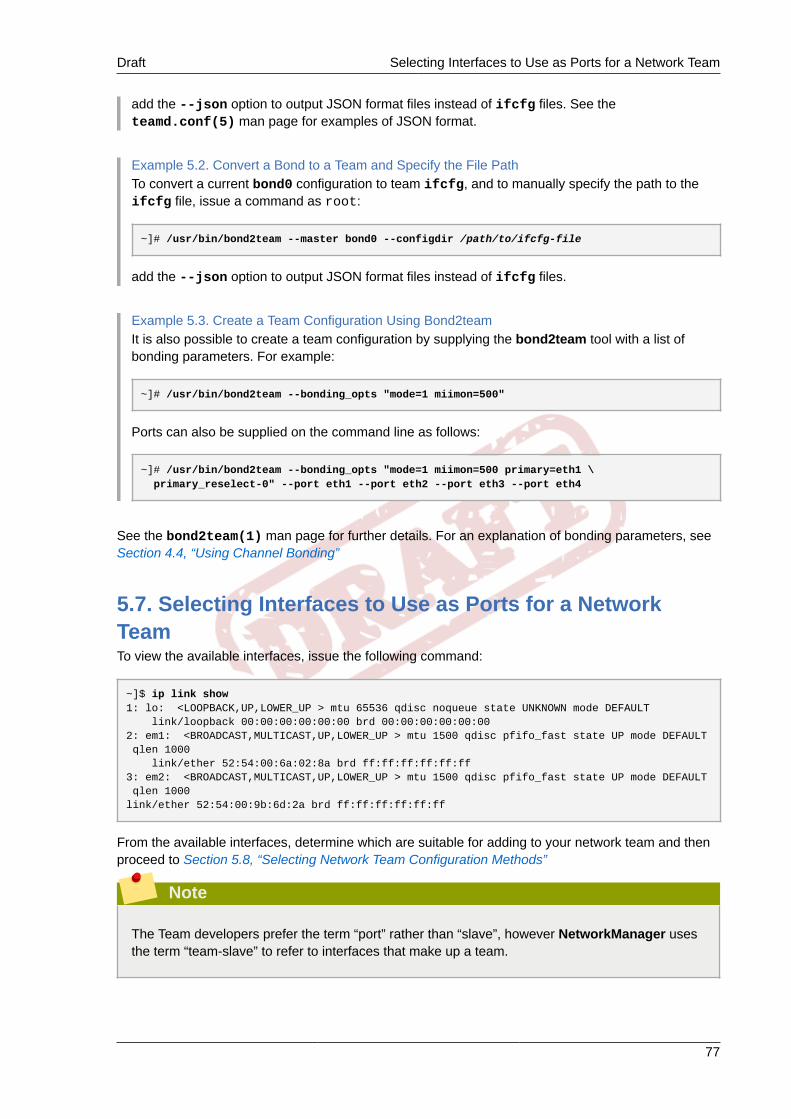
Draft Selecting Interfaces to Use as Ports for a Network Team
77
add the --json option to output JSON format files instead of ifcfg files. See theteamd.conf(5) man page for examples of JSON format.
Example 5.2. Convert a Bond to a Team and Specify the File PathTo convert a current bond0 configuration to team ifcfg, and to manually specify the path to theifcfg file, issue a command as root:
~]# /usr/bin/bond2team --master bond0 --configdir /path/to/ifcfg-file
add the --json option to output JSON format files instead of ifcfg files.
Example 5.3. Create a Team Configuration Using Bond2teamIt is also possible to create a team configuration by supplying the bond2team tool with a list ofbonding parameters. For example:
~]# /usr/bin/bond2team --bonding_opts "mode=1 miimon=500"
Ports can also be supplied on the command line as follows:
~]# /usr/bin/bond2team --bonding_opts "mode=1 miimon=500 primary=eth1 \ primary_reselect-0" --port eth1 --port eth2 --port eth3 --port eth4
See the bond2team(1) man page for further details. For an explanation of bonding parameters, seeSection 4.4, “Using Channel Bonding”
5.7. Selecting Interfaces to Use as Ports for a NetworkTeamTo view the available interfaces, issue the following command:
~]$ ip link show1: lo: <LOOPBACK,UP,LOWER_UP > mtu 65536 qdisc noqueue state UNKNOWN mode DEFAULT link/loopback 00:00:00:00:00:00 brd 00:00:00:00:00:002: em1: <BROADCAST,MULTICAST,UP,LOWER_UP > mtu 1500 qdisc pfifo_fast state UP mode DEFAULT qlen 1000 link/ether 52:54:00:6a:02:8a brd ff:ff:ff:ff:ff:ff3: em2: <BROADCAST,MULTICAST,UP,LOWER_UP > mtu 1500 qdisc pfifo_fast state UP mode DEFAULT qlen 1000link/ether 52:54:00:9b:6d:2a brd ff:ff:ff:ff:ff:ff
From the available interfaces, determine which are suitable for adding to your network team and thenproceed to Section 5.8, “Selecting Network Team Configuration Methods”
Note
The Team developers prefer the term “port” rather than “slave”, however NetworkManager usesthe term “team-slave” to refer to interfaces that make up a team.

Chapter 5. Configure Network Teaming Draft
78
5.8. Selecting Network Team Configuration MethodsTo configure a network team using a graphical user interface, see Section 5.9, “Creating aNetwork Team Using a GUI”
To create a network team using the Team daemon, teamd, proceed to Section 5.10.1, “Creating aNetwork Team Using teamd”.
To create a network team using configuration files, proceed to Section 5.10.2, “Creating a NetworkTeam Using ifcfg Files”.
To create a network team using the command-line tool, nmcli, proceed to Section 5.13, “ConfigureNetwork Teaming Using nmcli”.
5.9. Creating a Network Team Using a GUI
5.9.1. Establishing a Team ConnectionYou can use the GNOME control-center utility to direct NetworkManager to create a team from twoor more Wired or InfiniBand connections. It is not necessary to create the connections to be teamedfirst. They can be configured as part of the process to configure the team. You must have the MACaddresses of the interfaces available in order to complete the configuration process.
Procedure 5.1. Adding a New Team ConnectionYou can configure a team connection by opening the Network window, clicking the plus symbol, andselecting Team from the list.
1. Press the Super key to enter the Activities Overview, type control network and then pressEnter. The Network settings tool appears.
2. Click the plus symbol to open the selection list. Select Team. The Editing Team Connection 1window appears.
3. On the Team tab, click Add and select the type of interface you want to use with the teamconnection. Click the Create button. Note that the dialog to select the port type only comes upwhen you create the first port; after that, it will automatically use that same type for all furtherports.
4. The Editing team0 port 1 window appears. Fill in the MAC address of the first interface to beadded to the team.
5. If custom port settings are to be applied, click on the Team Port tab and enter a JSONconfiguration string or import it from a file.
6. Click the Save button.
7. The name of the teamed port appears in the Teamed connections window. Click the Add buttonto add further port connections.
8. Review and confirm the settings and then click the Save button.
9. Edit the team-specific settings by referring to Section 5.9.1.1, “Configuring the Team Tab” below.
Procedure 5.2. Editing an Existing Team ConnectionFollow these steps to edit an existing bond connection.

Draft Establishing a Team Connection
79
1. Press the Super key to enter the Activities Overview, type control network and then pressEnter. The Network settings tool appears.
2. Select the connection you want to edit and click the Options button.
3. Select the General tab.
4. Configure the connection name, auto-connect behavior, and availability settings.
Five settings in the Editing dialog are common to all connection types, see the General tab:
• Connection name — Enter a descriptive name for your network connection. This name will beused to list this connection in the menu of the Network window.
• Automatically connect to this network when it is available — Select this box if you wantNetworkManager to auto-connect to this connection when it is available. See Section 2.2.3,“Connecting to a Network Automatically” for more information.
• All users may connect to this network — Select this box to create a connection available toall users on the system. Changing this setting may require root privileges. See Section 2.2.4,“System-wide and Private Connection Profiles” for details.
• Automatically connect to VPN when using this connection — Select this box if you wantNetworkManager to auto-connect to a VPN connection when it is available. Select the VPNfrom the drop-down menu.
• Firewall Zone — Select the firewall zone from the drop-down menu.
5. Edit the team-specific settings by referring to Section 5.9.1.1, “Configuring the Team Tab” below.
Saving Your New (or Modified) Connection and Making FurtherConfigurationsOnce you have finished editing your team connection, click the Save button to save your customizedconfiguration. If the profile was in use while being edited, power cycle the connection to makeNetworkManager apply the changes. If the profile is OFF, set it to ON. See Section 2.2.1, “Connectingto a Network Using a GUI” for information on using your new or altered connection.
You can further configure an existing connection by selecting it in the Network window and clickingOptions to return to the Editing dialog.
Then, to configure:
• IPv4 settings for the connection, click the IPv4 Settings tab and proceed to Section 2.2.10.4,“Configuring IPv4 Settings”; or,
• IPv6 settings for the connection, click the IPv6 Settings tab and proceed to Section 2.2.10.5,“Configuring IPv6 Settings”.
5.9.1.1. Configuring the Team TabIf you have already added a new team connection you can enter a custom JSON configuration stringin the text box or import a configuration file. Click Save to apply the JSON configuration to the teaminterface.
For examples of JSON strings, see Section 5.12, “Configure teamd Runners”
See Procedure 5.1, “Adding a New Team Connection” for instructions on how to add a new team.
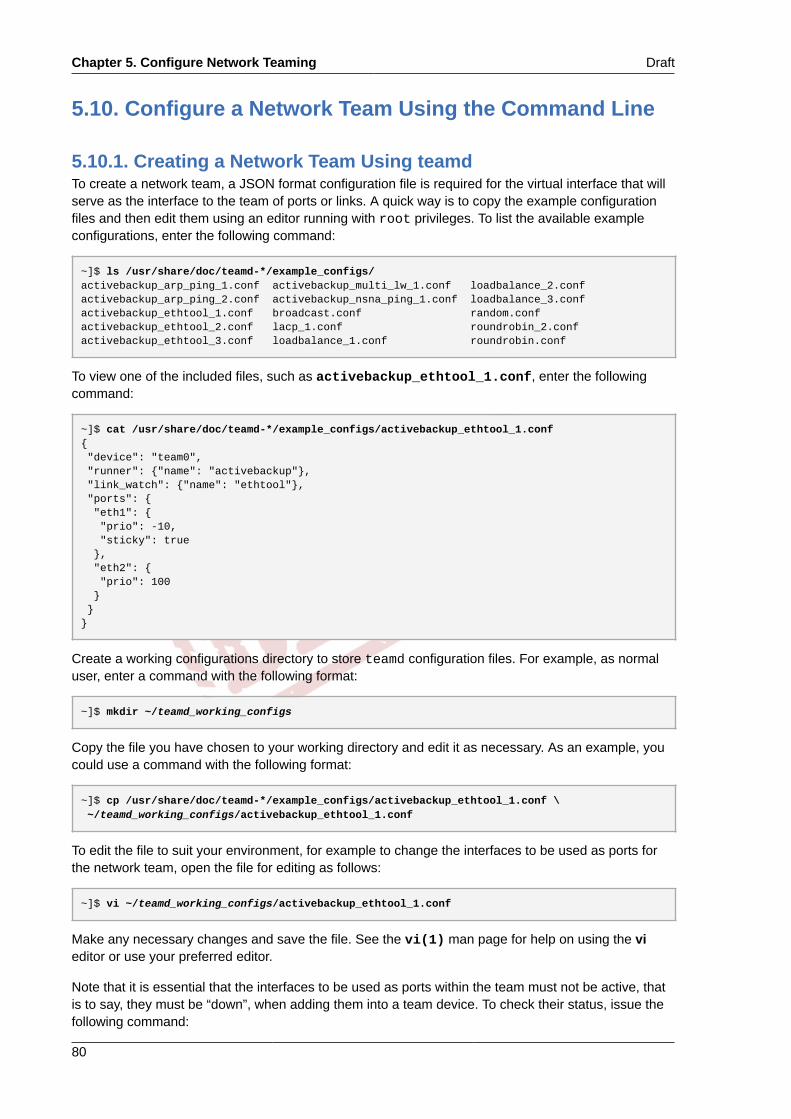
Chapter 5. Configure Network Teaming Draft
80
5.10. Configure a Network Team Using the Command Line
5.10.1. Creating a Network Team Using teamdTo create a network team, a JSON format configuration file is required for the virtual interface that willserve as the interface to the team of ports or links. A quick way is to copy the example configurationfiles and then edit them using an editor running with root privileges. To list the available exampleconfigurations, enter the following command:
~]$ ls /usr/share/doc/teamd-*/example_configs/activebackup_arp_ping_1.conf activebackup_multi_lw_1.conf loadbalance_2.confactivebackup_arp_ping_2.conf activebackup_nsna_ping_1.conf loadbalance_3.confactivebackup_ethtool_1.conf broadcast.conf random.confactivebackup_ethtool_2.conf lacp_1.conf roundrobin_2.confactivebackup_ethtool_3.conf loadbalance_1.conf roundrobin.conf
To view one of the included files, such as activebackup_ethtool_1.conf, enter the followingcommand:
~]$ cat /usr/share/doc/teamd-*/example_configs/activebackup_ethtool_1.conf{ "device": "team0", "runner": {"name": "activebackup"}, "link_watch": {"name": "ethtool"}, "ports": { "eth1": { "prio": -10, "sticky": true }, "eth2": { "prio": 100 } }}
Create a working configurations directory to store teamd configuration files. For example, as normaluser, enter a command with the following format:
~]$ mkdir ~/teamd_working_configs
Copy the file you have chosen to your working directory and edit it as necessary. As an example, youcould use a command with the following format:
~]$ cp /usr/share/doc/teamd-*/example_configs/activebackup_ethtool_1.conf \ ~/teamd_working_configs/activebackup_ethtool_1.conf
To edit the file to suit your environment, for example to change the interfaces to be used as ports forthe network team, open the file for editing as follows:
~]$ vi ~/teamd_working_configs/activebackup_ethtool_1.conf
Make any necessary changes and save the file. See the vi(1) man page for help on using the vieditor or use your preferred editor.
Note that it is essential that the interfaces to be used as ports within the team must not be active, thatis to say, they must be “down”, when adding them into a team device. To check their status, issue thefollowing command:

Draft Creating a Network Team Using teamd
81
~]$ ip link show1: lo: <LOOPBACK,UP,LOWER_UP> mtu 65536 qdisc noqueue state UNKNOWN mode DEFAULT link/loopback 00:00:00:00:00:00 brd 00:00:00:00:00:002: em1: <BROADCAST,MULTICAST,UP,LOWER_UP> mtu 1500 qdisc pfifo_fast state UP mode DEFAULT qlen 1000 link/ether 52:54:00:d5:f7:d4 brd ff:ff:ff:ff:ff:ff3: em2: <BROADCAST,MULTICAST,UP,LOWER_UP> mtu 1500 qdisc pfifo_fast state UP mode DEFAULT qlen 1000 link/ether 52:54:00:d8:04:70 brd ff:ff:ff:ff:ff:ff
In this example we see that both the interfaces we plan to use are “UP”.
To take down an interface, issue a command as root in the following format:
~]# ip link set down em1
Repeat for each interface as necessary.
To create a team interface based on the configuration file, as root user, change to the workingconfigurations directory (teamd_working_configs in this example):
~]# cd /home/userteamd_working_configs
Then issue a command in the following format:
~]# teamd -g -f activebackup_ethtool_1.conf -dUsing team device "team0".Using PID file "/var/run/teamd/team0.pid"Using config file "/home/user/teamd_working_configs/activebackup_ethtool_1.conf"
The -g option is for debug messages, -f option is to specify the configuration file to load, and the -doption is to make the process run as a daemon after startup. See the teamd(8) man page for otheroptions.
To check the status of the team, issue the following command as root:
~]# teamdctl team0 statesetup: runner: activebackupports: em1 link watches: link summary: up instance[link_watch_0]: name: ethtool link: up em2 link watches: link summary: up instance[link_watch_0]: name: ethtool link: uprunner: active port: em1
To apply an address to the network team interface, team0, issue a command as root in the followingformat:
~]# ip addr add 192.168.23.2/24 dev team0

Chapter 5. Configure Network Teaming Draft
82
To check the IP address of a team interface, issue a command as follows:
~]$ ip addr show team04: team0: <BROADCAST,MULTICAST,UP,LOWER_UP> mtu 1500 qdisc noqueue state UP link/ether 16:38:57:60:20:6f brd ff:ff:ff:ff:ff:ff inet 192.168.23.2/24 scope global team0 valid_lft forever preferred_lft forever inet6 2620:52:0:221d:1438:57ff:fe60:206f/64 scope global dynamic valid_lft 2591880sec preferred_lft 604680sec inet6 fe80::1438:57ff:fe60:206f/64 scope link valid_lft forever preferred_lft forever
To activate the team interface, or to bring it “up”, issue a command as root in the following format:
~]# ip link set dev team0 up
To temporarily deactivate the team interface, or to take it “down”, issue a command as root in thefollowing format:
~]# ip link set dev team0 down
To terminate, or kill, an instance of the team daemon, as root user, issue a command in the followingformat:
~]# teamd -t team0 -k
The -k option is to specify that the instance of the daemon associated with the device team0 is to bekilled. See the teamd(8) man page for other options.
For help on command-line options for teamd, issue the following command:
~]$ teamd -h
In addition, see the teamd(8) man page.
5.10.2. Creating a Network Team Using ifcfg FilesTo create a networking team using ifcfg files, create a file in the /etc/sysconfig/network-scripts/ directory as follows:
DEVICE=team0DEVICETYPE=TeamONBOOT=yesBOOTPROTO=noneIPADDR=192.168.11.1PREFIX=24TEAM_CONFIG='{"runner": {"name": "activebackup"}, "link_watch": {"name": "ethtool"}}'
This creates the interface to the team, in other words, this is the master.
To create a port to be a member of team0, create one or more files in the /etc/sysconfig/network-scripts/ directory as follows:
DEVICE=eth1HWADDR=D4:85:64:01:46:9EDEVICETYPE=TeamPortONBOOT=yes

Draft Add a Port to a Network Team Using iputils
83
TEAM_MASTER=team0TEAM_PORT_CONFIG='{"prio": 100}'
Add additional port interfaces similar to the above as required, changing the DEVICE and HWADDRfield to match the ports (the network devices) being added. If port priority is not specified by prio itdefaults to 0; it accepts negative and positive values in the range -32,767 to +32,767.
Specifying the hardware or MAC address using the HWADDR directive will influence the device namingprocedure. This is explained in Chapter 8, Consistent Network Device Naming.
To bring up the network team, issue the following command as root:
~]# ifup team0
To view the network team, issue the following command:
~]$ ip link show
5.10.3. Add a Port to a Network Team Using iputilsTo add a port em1 to a network team team0, using the ip utility, issue the following commands asroot:
~]# ip link set dev em1 down~]# ip link set dev em1 master team0
Add additional ports as required. Team driver will bring ports up automatically.
5.10.4. Listing the ports of a Team Using teamnlTo view or list the ports in a network team, using the teamnl utility, issue the following command asroot:
~]# teamnl team0 portsem2: up 100 fullduplexem1: up 100 fullduplex
5.10.5. Configuring Options of a Team Using teamnlTo view or list all currently available options, using the teamnl utility, issue the following command asroot:
~]# teamnl team0 options
To configure a team to use active backup mode, issue the following command as root:
~]# teamnl team0 setoption mode activebackup
5.10.6. Add an Address to a Network Team Using iputilsTo add an address to a team team0, using the ip utility, issue the following command as root:
~]# ip addr add 192.168.252.2/24 dev team0
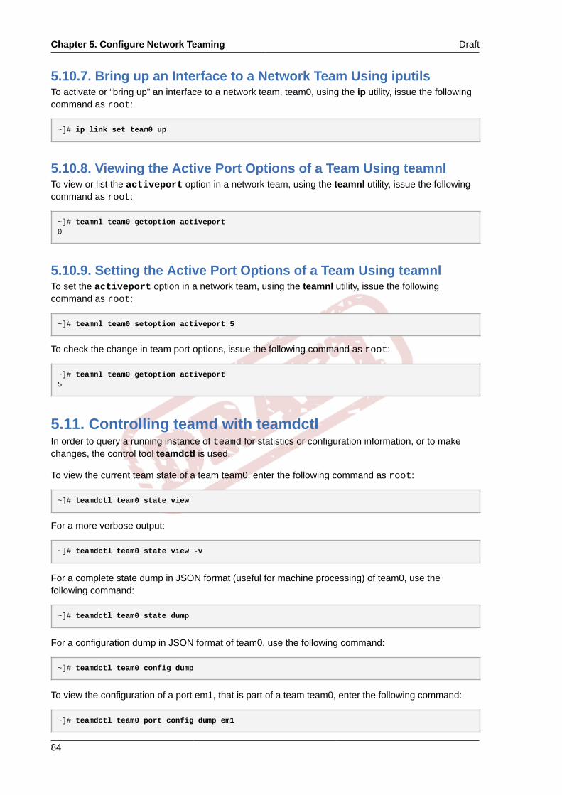
Chapter 5. Configure Network Teaming Draft
84
5.10.7. Bring up an Interface to a Network Team Using iputilsTo activate or “bring up” an interface to a network team, team0, using the ip utility, issue the followingcommand as root:
~]# ip link set team0 up
5.10.8. Viewing the Active Port Options of a Team Using teamnlTo view or list the activeport option in a network team, using the teamnl utility, issue the followingcommand as root:
~]# teamnl team0 getoption activeport0
5.10.9. Setting the Active Port Options of a Team Using teamnlTo set the activeport option in a network team, using the teamnl utility, issue the followingcommand as root:
~]# teamnl team0 setoption activeport 5
To check the change in team port options, issue the following command as root:
~]# teamnl team0 getoption activeport5
5.11. Controlling teamd with teamdctlIn order to query a running instance of teamd for statistics or configuration information, or to makechanges, the control tool teamdctl is used.
To view the current team state of a team team0, enter the following command as root:
~]# teamdctl team0 state view
For a more verbose output:
~]# teamdctl team0 state view -v
For a complete state dump in JSON format (useful for machine processing) of team0, use thefollowing command:
~]# teamdctl team0 state dump
For a configuration dump in JSON format of team0, use the following command:
~]# teamdctl team0 config dump
To view the configuration of a port em1, that is part of a team team0, enter the following command:
~]# teamdctl team0 port config dump em1

Draft Add a Port to a Network Team
85
5.11.1. Add a Port to a Network TeamTo add a port em1 to a network team team0, issue the following command as root:
~]# teamdctl team0 port add em1
5.11.2. Remove a Port From a Network TeamTo remove an interface em1 from a network team team0, issue the following command as root:
~]# teamdctl team0 port remove em1
5.11.3. Apply a Configuration to a Port in a Network TeamTo apply a JSON format configuration to a port em1 in a network team team0, issue a command asroot in the following format:
~]# teamdctl team0 port config update em1 JSON-config-string
Where JSON-config-string is the configuration as a string of text in JSON format. This will updatethe configuration of the port using the JSON format string supplied. An example of a valid JSON stringfor configuring a port would be the following:
{ "prio": -10, "sticky": true}
Use single quotes around the JSON configuration string and omit the line breaks.
Note that the old configuration will be overwritten and that any options omitted will be reset to thedefault values. See the teamdctl(8) man page for more team daemon control tool commandexamples.
5.11.4. View the Configuration of a Port in a Network TeamTo copy the configuration of a port em1 in a network team team0, issue the following command asroot:
~]# teamdctl team0 port config dump em1
This will dump the JSON format configuration of the port to standard output.
5.12. Configure teamd RunnersRunners are units of code which are compiled into the Team daemon when an instance of the daemonis created. For an introduction to the teamd runners, see Section 5.4, “Understanding the NetworkTeaming Daemon and the "Runners"”.
5.12.1. Configure the broadcast RunnerTo configure the broadcast runner, using an editor as root, add the following to the team JSONformat configuration file:

Chapter 5. Configure Network Teaming Draft
86
{ "device": "team0", "runner": {"name": "broadcast"}, "ports": {"em1": {}, "em2": {}}}
Please see the teamd.conf(5) man page for more information.
5.12.2. Configure the random RunnerThe random runner behaves similarly to the roundrobin runner.
To configure the random runner, using an editor as root, add the following to the team JSON formatconfiguration file:
{ "device": "team0", "runner": {"name": "random"}, "ports": {"em1": {}, "em2": {}}}
Please see the teamd.conf(5) man page for more information.
5.12.3. Configure the roundrobin RunnerTo configure the roundrobin runner, using an editor as root, add the following to the team JSONformat configuration file:
{ "device": "team0", "runner": {"name": "roundrobin"}, "ports": {"em1": {}, "em2": {}}}
A very basic configuration for roundrobin.
Please see the teamd.conf(5) man page for more information.
5.12.4. Configure the activebackup RunnerThe active backup runner can use all of the link-watchers to determine the status of links in a team.Any one of the following examples can be added to the team JSON format configuration file:
{ "device": "team0", "runner": { "name": "activebackup" }, "link_watch": { "name": "ethtool" }, "ports": { "em1": { "prio": -10, "sticky": true },

Draft Configure the activebackup Runner
87
"em2": { "prio": 100 } }}
This example configuration uses the active-backup runner with ethtool as the link watcher. Port em2has higher priority. The sticky flag ensures that if em1 becomes active, it stays active as long as thelink remains up.
{ "device": "team0", "runner": { "name": "activebackup" }, "link_watch": { "name": "ethtool" }, "ports": { "em1": { "prio": -10, "sticky": true, "queue_id": 4 }, "em2": { "prio": 100 } }}
This example configuration adds a queue ID of 4. It uses active-backup runner with ethtool as thelink watcher. Port em2 has higher priority. But the sticky flag ensures that if em1 becomes active, it willstay active as long as the link remains up.
To configure the activebackup runner using ethtool as the link watcher and applying a delay, using aneditor as root, add the following to the team JSON format configuration file:
{ "device": "team0", "runner": { "name": "activebackup" }, "link_watch": { "name": "ethtool", "delay_up": 2500, "delay_down": 1000 }, "ports": { "em1": { "prio": -10, "sticky": true }, "em2": { "prio": 100 } }}
This example configuration uses the active-backup runner with ethtool as the link watcher. Port em2has higher priority. But the sticky flag ensures that if em1 becomes active, it stays active while the linkremains up. Link changes are not propagated to the runner immediately, but delays are applied.

Chapter 5. Configure Network Teaming Draft
88
Please see the teamd.conf(5) man page for more information.
5.12.5. Configure the loadbalance RunnerThis runner can be used for two types of load balancing, active and passive. In active mode, constantre-balancing of traffic is done by using statistics of recent traffic to share out traffic as evenly aspossible. In static mode, streams of traffic are distributed randomly across the available links. This hasa speed advantage due to lower processing overhead. In high volume traffic applications this is oftenpreferred as traffic usually consists of multiple stream which will be distributed randomly between theavailable links, in this way load sharing is accomplished without intervention by teamd.
To configure the loadbalance runner for passive transmit (Tx) load balancing, using an editor as root,add the following to the team JSON format configuration file:
{ "device": "team0", "runner": { "name": "loadbalance", "tx_hash": ["eth", "ipv4", "ipv6"] }, "ports": {"em1": {}, "em2": {}}}
Configuration for hash-based passive transmit (Tx) load balancing.
To configure the loadbalance runner for active transmit (Tx) load balancing, using an editor as root,add the following to the team JSON format configuration file:
{ "device": "team0", "runner": { "name": "loadbalance", "tx_hash": ["eth", "ipv4", "ipv6"], "tx_balancer": { "name": "basic" } }, "ports": {"em1": {}, "em2": {}}}
Configuration for active transmit (Tx) load balancing using basic load balancer.
Please see the teamd.conf(5) man page for more information.
5.12.6. Configure the LACP (802.3ad) RunnerTo configure the LACP runner using ethtool as a link watcher, using an editor as root, add thefollowing to the team JSON format configuration file:
{ "device": "team0", "runner": { "name": "lacp", "active": true, "fast_rate": true, "tx_hash": ["eth", "ipv4", "ipv6"] },

Draft Configure Monitoring of the Link State
89
"link_watch": {"name": "ethtool"}, "ports": {"em1": {}, "em2": {}}}
Configuration for connection to a link aggregation control protocol (LACP) capable counterpart. TheLACP runner should use ethtool to monitor the status of a link. It does not make sense to use anyother link monitoring method besides the ethtool because, for example in the case of arp_ping, thelink would never come up. The reason is that the link has to be established first and only after that canpackets, ARP included, go through. Using ethtool prevents this because it monitors each link layerindividually.
Active load balancing is possible with this runner in the same way as it is done for the loadbalancerunner. To enable active transmit (Tx) load balancing, add the following section:
"tx_balancer": { "name": "basic"}
Please see the teamd.conf(5) man page for more information.
5.12.7. Configure Monitoring of the Link StateThe following methods of link state monitoring are available. To implement one of the methods, addthe JSON format string to the team JSON format configuration file using an editor running with rootprivileges.
5.12.7.1. Configure Ethtool for link-state MonitoringTo add or edit an existing delay, in milliseconds, between the link coming up and the runner beingnotified about it, add or edit a section as follows:
"link_watch": { "name": "ethtool", "delay_up": 2500}
To add or edit an existing delay, in milliseconds, between the link going down and the runner beingnotified about it, add or edit a section as follows:
"link_watch": { "name": "ethtool", "delay_down": 1000}
5.12.7.2. Configure ARP Ping for Link-state MonitoringThe team daemon teamd sends an ARP REQUEST to an address at the remote end of the link inorder to determine if the link is up. The method used is the same as the arping utility but it does notuse that utility.
Prepare a file containing the new configuration in JSON format similar to the following example:
{ "device": "team0",

Chapter 5. Configure Network Teaming Draft
90
"runner": {"name": "activebackup"}, "link_watch":{ "name": "arp_ping", "interval": 100, "missed_max": 30, "source_host": "192.168.23.2", "target_host": "192.168.23.1" }, "ports": { "em1": { "prio": -10, "sticky": true }, "em2": { "prio": 100 } }}
This configuration uses arp_ping as the link watcher. The missed_max option is a limit value ofthe maximum allowed number of missed replies (ARP replies for example). It should be chosen inconjunction with the interval option in order to determine the total time before a link is reported asdown.
To load a new configuration for a team port em2, from a file containing a JSON configuration, issue thefollowing command as root:
~]# port config update em2 JSON-config-file
Note that the old configuration will be overwritten and that any options omitted will be reset to thedefault values. See the teamdctl(8) man page for more team daemon control tool commandexamples.
5.12.7.3. Configure IPv6 NA/NS for Link-state Monitoring
{ "device": "team0", "runner": {"name": "activebackup"}, "link_watch": { "name": "nsna_ping", "interval": 200, "missed_max": 15, "target_host": "fe80::210:18ff:feaa:bbcc" }, "ports": { "em1": { "prio": -10, "sticky": true }, "em2": { "prio": 100 } }}
To configure the interval between sending NS/NA packets, add or edit a section as follows:
"link_watch": { "name": "nsna_ping",
Draft Configure Port Selection Override
91
"interval": 200}
Value is positive number in milliseconds. It should be chosen in conjunction with the missed_maxoption in order to determine the total time before a link is reported as down.
To configure the maximum number of missed NS/NA reply packets to allow before reporting the link asdown, add or edit a section as follows:
"link_watch": { "name": "nsna_ping", "missed_max": 15}
Maximum number of missed NS/NA reply packets. If this number is exceeded, the link is reported asdown. The missed_max option is a limit value of the maximum allowed number of missed replies(ARP replies for example). It should be chosen in conjunction with the interval option in order todetermine the total time before a link is reported as down.
To configure the host name that is resolved to the IPv6 address target address for the NS/NApackets, add or edit a section as follows:
"link_watch": { "name": "nsna_ping", "target_host": "MyStorage"}
The “target_host” option contains the host name to be converted to an IPv6 address which will beused as the target address for the NS/NA packets. An IPv6 address can be used in place of a hostname.
Please see the teamd.conf(5) man page for more information.
5.12.8. Configure Port Selection OverrideThe physical port which transmits a frame is normally selected by the kernel part of the team driver,and is not relevant to the user or system administrator. The output port is selected using the policiesof the selected team mode (teamd runner). On occasion however, it is helpful to direct certain classesof outgoing traffic to certain physical interfaces to implement slightly more complex policies. By defaultthe team driver is multiqueue aware and 16 queues are created when the driver initializes (see https://www.kernel.org/doc/Documentation/networking/multiqueue.txt for details). If more or less queues aredesired, the Netlink attribute tx_queues can be used to change this value during the team driverinstance creation.
The queue ID for a port can be set by the port configuration option queue_id as follows:
{ "queue_id": 3}
These queue ID's can be used in conjunction with the tc utility to configure a multiqueue queuediscipline and filters to bias certain traffic to be transmitted on certain port devices. For example, ifusing the above configuration and wanting to force all traffic bound to 192.168.1.100 to use eth1 inthe team as its output device, issue commands as root in the following format:

Chapter 5. Configure Network Teaming Draft
92
~]# tc qdisc add dev team0 handle 1 root multiq~]# tc filter add dev team0 protocol ip parent 1: prio 1 u32 match ip dst \ 192.168.1.100 action skbedit queue_mapping 3
This mechanism of overriding runner selection logic in order to bind traffic to a specific port can beused with all runners.
5.12.9. Configure BPF-based Tx Port SelectorsThe loadbalance and LACP runners uses hashes of packets to sort network traffic flow. The hashcomputation mechanism is based on the Berkeley Packet Filter (BPF) code. The BPF code is usedto generate a hash rather than make a policy decision for outgoing packets. The hash length is 8bits giving 256 variants. This means many different socket buffers (SKB) can have the same hashand therefore pass traffic over the same link. The use of a short hash is a quick way to sort trafficinto different streams for the purposes of load balancing across multiple links. In static mode, thehash is only used to decide out of which port the traffic should be sent. In active mode, the runner willcontinually reassign hashes to different ports in an attempt to reach a perfect balance.
The following fragment types or strings can be used for packet Tx hash computation:• eth — Uses source and destination MAC addresses.
• vlan — Uses VLAN ID.
• ipv4 — Uses source and destination IPv4 addresses.
• ipv6 — Uses source and destination IPv6 addresses.
• ip — Uses source and destination IPv4 and IPv6 addresses.
• l3 — Uses source and destination IPv4 and IPv6 addresses.
• tcp — Uses source and destination TCP ports.
• udp — Uses source and destination UDP ports.
• sctp — Uses source and destination SCTP ports.
• l4 — Uses source and destination TCP and UDP and SCTP ports.
These strings can be used by adding a line in the following format to the load balance runner:
"tx_hash": ["eth", "ipv4", "ipv6"]
See Section 5.12.5, “Configure the loadbalance Runner” for an example.
5.13. Configure Network Teaming Using nmcliTo view the devices available on the system, issue the following command:
~]$ nmcli connection showNAME UUID TYPE DEVICEeth1 0e8185a1-f0fd-4802-99fb-bedbb31c689b 802-3-ethernet --eth0 dfe1f57b-419d-4d1c-aaf5-245deab82487 802-3-ethernet --
To create a new team interface, with name team-ServerA, issue a command as follows:
~]$ nmcli connection add type team ifname team-ServerA

Draft Configure Network Teaming Using nmcli
93
Connection 'team-ServerA' (b954c62f-5fdd-4339-97b0-40efac734c50) successfully added.
NetworkManager will set its internal parameter connection.autoconnect to yes and as no IPaddress was given ipv4.method will be set to auto. NetworkManager will also write a configurationfile to /etc/sysconfig/network-scripts/ifcfg-team-ServerA where the correspondingONBOOT will be set to yes and BOOTPROTO will be set to dhcp.
Note that manual changes to the ifcfg file will not be noticed by NetworkManager until the interface isnext brought up. See Section 1.7, “Network Configuration Using sysconfig Files” for more informationon using configuration files.
To view the other values assigned, issue a command as follows:
~]$ nmcli con show team-ServerAconnection.id: team-ServerAconnection.uuid: b954c62f-5fdd-4339-97b0-40efac734c50connection.interface-name: ServerAconnection.type: teamconnection.autoconnect: yes…ipv4.method: auto[output truncated]
As no JSON configuration file was specified the default values apply. See the teamd.conf(5) manpage for more information on the team JSON parameters and their default values. Notice that thename was derived from the interface name by prepending the type. Alternatively, specify a name withthe con-name option as follows:
~]$ nmcli connection add type team con-name Team0 ifname ServerBConnection 'Team0' (5f7160a1-09f6-4204-8ff0-6d96a91218a7) successfully added.
To view the team interfaces just configured, issue a command as follows:
~]$ nmcli con showNAME UUID TYPE DEVICEteam-ServerA b954c62f-5fdd-4339-97b0-40efac734c50 team ServerAeth1 0e8185a1-f0fd-4802-99fb-bedbb31c689b 802-3-ethernet -- eth0 dfe1f57b-419d-4d1c-aaf5-245deab82487 802-3-ethernet --Team0 5f7160a1-09f6-4204-8ff0-6d96a91218a7 team ServerB
To change the name assigned to a team, issue a command in the following format:
nmcli con mod old-team-name connection.id new-team-name
To load a team configuration file for a team that already exists, issue a command in the followingformat:
nmcli connection modify team-name team.config JSON-config
You can specify the team configuration either as a JSON string or provide a file name containing theconfiguration. The file name can include the path. In both cases, what is stored in the team.configproperty is the JSON string. In the case of a JSON string, use single quotes around the string andpaste the entire string to the command line.
To review the team.config property, enter a command in the following format:
nmcli con show team-name | grep team.config

Chapter 5. Configure Network Teaming Draft
94
To add an interface eth0 to Team0, with the name Team0-port1, issue a command as follows:
~]$ nmcli con add type team-slave con-name Team0-port1 ifname eth0 master Team0Connection 'Team0-port1' (ccd87704-c866-459e-8fe7-01b06cf1cffc) successfully added.
Similarly, to add another interface, eth1, with the name Team0-port2, issue a command as follows:
~]$ nmcli con add type team-slave con-name Team0-port2 ifname eth1 master Team0Connection 'Team0-port2' (a89ccff8-8202-411e-8ca6-2953b7db52dd) successfully added.
At time of writing, nmcli only supports Ethernet ports.
In order to bring up a team, the ports must be brought up first as follows:
~]$ nmcli connection up Team0-port1Connection successfully activated (D-Bus active path: /org/freedesktop/NetworkManager/ActiveConnection/2)
~]$ nmcli connection up Team0-port2Connection successfully activated (D-Bus active path: /org/freedesktop/NetworkManager/ActiveConnection/3)
You can verify that the team interface was brought up by the activation of the ports, as follows:
~]$ ip link3: Team0: <BROADCAST,MULTICAST,UP,LOWER_UP> mtu 1500 qdisc noqueue state UP mode DEFAULT link/ether 52:54:00:76:6f:f0 brd ff:ff:ff:ff:ff:f
Alternatively, issue a command to bring up the team as follows:
~]$ nmcli connection up Team0Connection successfully activated (D-Bus active path: /org/freedesktop/NetworkManager/ActiveConnection/4)
See Section 2.4, “Using the NetworkManager Command Line Tool, nmcli” for an introduction to nmcli
5.14. Additional ResourcesThe following sources of information provide additional resources regarding network teaming.
5.14.1. Installed Documentation• teamd(8) man page — Describes the teamd service.
• teamdctl(8) man page — Describes the teamd control tool.
• teamd.conf(5) man page — Describes the teamd configuration file.
• teamnl(8) man page — Describes the teamd Netlink library.
• bond2team(1) man page — Describes a tool to convert bonding options to team.
5.14.2. Online Documentationhttp://www.libteam.org
The upstream project.

Draft Online Documentation
95
http://www.w3schools.com/json/json_syntax.aspAn explanation of JSON syntax.

96

Draft Chapter 6. Draft
97
Configure Network BridgingA network bridge is a link-layer device which forwards traffic between networks based on MACaddresses. It makes forwarding decisions based on a table of MAC addresses which it buildsby listening to network traffic and thereby learning what hosts are connected to each network. Asoftware bridge can be used within a Linux host in order to emulate a hardware bridge, for example invirtualization applications for sharing a NIC with one or more virtual NICs.
Note that a bridge cannot be established over Wi-Fi networks operating in Ad-Hoc or Infrastructuremodes. This is due to the IEEE 802.11 standard that specifies the use of 3-address frames in Wi-Fi forthe efficient use of airtime. A system configured to be an access point (AP) running the hostapd cansupport the necessary 4-address frames.
6.1. Configure Network Bridging Using a GUIWhen starting a bridge interface, NetworkManager waits for at least one port to enter the“forwarding” state before beginning any network-dependent IP configuration such as DHCP orIPv6 autoconfiguration. Static IP addressing is allowed to proceed before any slaves or ports areconnected or begin forwarding packets.
6.1.1. Establishing a Bridge ConnectionProcedure 6.1. Adding a New Bridge ConnectionYou can configure a new Bridge connection by opening the Network window and selecting the plussymbol below the menu.
1. To use the graphical Network settings tool, press the Super key to enter the Activities Overview,type control network and then press Enter. The Network settings tool appears.
2. Select the plus symbol below the menu. The Add Network Connection window appears.
3. Select the Bridge menu entry. The Editing Bridge connection 1 window appears.
Procedure 6.2. Editing an Existing Bridge ConnectionYou can configure an existing bridge connection by opening the Network window and selecting thename of the connection from the list. Then click the Edit button.
1. Press the Super key to enter the Activities Overview, type control network and then pressEnter. The Network settings tool appears.
2. Select the Bridge connection you want to edit from the left hand menu.
3. Click the Options button.
Configuring the Connection Name, Auto-Connect Behavior, andAvailability SettingsFive settings in the Editing dialog are common to all connection types, see the General tab:
• Connection name — Enter a descriptive name for your network connection. This name will be usedto list this connection in the menu of the Network window.
• Automatically connect to this network when it is available — Select this box if you wantNetworkManager to auto-connect to this connection when it is available. See Section 2.2.3,“Connecting to a Network Automatically” for more information.

Chapter 6. Configure Network Bridging Draft
98
• All users may connect to this network — Select this box to create a connection available to allusers on the system. Changing this setting may require root privileges. See Section 2.2.4, “System-wide and Private Connection Profiles” for details.
• Automatically connect to VPN when using this connection — Select this box if you wantNetworkManager to auto-connect to a VPN connection when it is available. Select the VPN fromthe dropdown menu.
• Firewall Zone — Select the Firewall Zone from the dropdown menu.
6.1.1.1. Configuring the Bridge Tab Interface name
The name of the interface to the bridge.
Bridged connectionsOne or more slave interfaces.
Aging timeThe time, in seconds, a MAC address is kept in the MAC address forwarding database.
Enable STP (Spanning Tree Protocol)If required, select the check box to enable STP.
PriorityThe bridge priority; the bridge with the lowest priority will be elected as the root bridge.
Forward delayThe time, in seconds, spent in both the Listening and Learning states before entering theForwarding state. The default is 15 seconds.
Hello timeThe time interval, in seconds, between sending configuration information in bridge protocol dataunits (BPDU).
Max ageThe maximum time, in seconds, to store the configuration information from BPDUs. This valueshould be twice the Hello Time plus 1 but less than twice the Forwarding delay minus 1.
Draft Establishing a Bridge Connection
99
Figure 6.1. Editing Bridge Connection 1
Procedure 6.3. Adding a Slave Interface to a Bridge1. To add a port to a bridge, select the Bridge tab in the Editing Bridge connection 1 window. If
necessary, open this window by following the procedure in Procedure 6.2, “Editing an ExistingBridge Connection”.
2. Click Add. The Choose a Connection Type menu appears.
Chapter 6. Configure Network Bridging Draft
100
3. Select the type of connection to be created from the list. Click Create. A window appropriate tothe connection type selected appears.
4. Select the Bridge Port tab. Configure Priority and Path cost as required. Note the STP priorityfor a bridge port is limited by the Linux kernel. Although the standard allows a range of 0 to 255,Linux only allows 0 to 63. The default is 32 in this case.
5. If required, select the Hairpin mode check box to enable forwarding of frames for externalprocessing. Also known as virtual Ethernet port aggregator (VEPA) mode.
Then, to configure:
• An Ethernet slave, click the Ethernet tab and proceed to Section 2.2.5.1, “Configuring theConnection Name, Auto-Connect Behavior, and Availability Settings”, or;
• A Bond slave, click the Bond tab and proceed to Section 4.2.1.1, “Configuring the Bond Tab”, or;
• A Team slave, click the Team tab and proceed to Section 5.9.1.1, “Configuring the Team Tab”, or;
• An VLAN slave, click the VLAN tab and proceed to Section 7.2.1.1, “Configuring the VLAN Tab”, or;
Saving Your New (or Modified) Connection and Making Further ConfigurationsOnce you have finished editing your new bridge connection, click the Save button to save yourcustomized configuration. If the profile was in use while being edited, power cycle the connectionto make NetworkManager apply the changes. If the profile is OFF, set it to ON. See Section 2.2.1,“Connecting to a Network Using a GUI” for information on using your new or altered connection.
You can further configure an existing connection by selecting it in the Network window and clickingOptions to return to the Editing dialog.
Then, to configure:
• IPv4 settings for the connection, click the IPv4 Settings tab and proceed to Section 2.2.10.4,“Configuring IPv4 Settings”, or;
• IPv6 settings for the connection, click the IPv6 Settings tab and proceed to Section 2.2.10.5,“Configuring IPv6 Settings”.
6.2. Using the Command Line Interface (CLI)
6.2.1. Check if Bridging Kernel Module is InstalledIn Fedora, the bridging module is loaded by default. If necessary, you can make sure that the moduleis loaded by issuing the following command as root:
~]# modprobe --first-time bridgemodprobe: ERROR: could not insert 'bridge': Module already in kernel
To display information about the module, issue the following command:
~]$ modinfo bridge
See the modprobe(8) man page for more command options.

Draft Create a Network Bridge
101
6.2.2. Create a Network BridgeTo create a network bridge, create a file in the /etc/sysconfig/network-scripts/ directorycalled ifcfg-brN, replacing N with the number for the interface, such as 0.
The contents of the file is similar to whatever type of interface is getting bridged to, such as anEthernet interface. The differences in this example are as follows:• The DEVICE directive is given an interface name as its argument in the format brN, where N is
replaced with the number of the interface.
• The TYPE directive is given an argument Bridge or Ethernet. This directive determines thedevice type and the argument is case sensitive.
• The bridge interface configuration file is given an IP address whereas the physical interfaceconfiguration file must only have a MAC address (see below).
• An extra directive, DELAY=0, is added to prevent the bridge from waiting while it monitors traffic,learns where hosts are located, and builds a table of MAC addresses on which to base its filteringdecisions. The default delay of 30 seconds is not needed if no routing loops are possible.
The following is a sample bridge interface configuration file using a static IP address:
Example 6.1. Sample ifcfg-br0 Interface Configuration File
DEVICE=br0TYPE=BridgeIPADDR=192.168.1.1PREFIX=24ONBOOT=yesBOOTPROTO=noneDELAY=0
To complete the bridge another interface is created, or an existing interface is modified, and pointed tothe bridge interface. The following is a sample Ethernet interface configuration file pointing to a bridgeinterface. Configure your physical interface in /etc/sysconfig/network-scripts/ifcfg-ethX,where X is a unique number corresponding to a specific interface, as follows:
Example 6.2. Sample ifcfg-ethX Interface Configuration File
DEVICE=ethXTYPE=EthernetHWADDR=AA:BB:CC:DD:EE:FFBOOTPROTO=noneONBOOT=yesBRIDGE=br0
Chapter 6. Configure Network Bridging Draft
102
Note
For the DEVICE directive, almost any interface name could be used as it does not determinethe device type. TYPE=Ethernet is not strictly required. If the TYPE directive is not set, thedevice is treated as an Ethernet device (unless it's name explicitly matches a different interfaceconfiguration file.)
Specifying the hardware or MAC address using the HWADDR directive will influence the device namingprocedure as explained in Chapter 8, Consistent Network Device Naming.
Warning
If you are configuring bridging on a remote host, and you are connected to that host over thephysical NIC you are configuring, please consider the implications of losing connectivity beforeproceeding. You will lose connectivity when restarting the service and may not be able to regainconnectivity if any errors have been made. Console, or out-of-band access is advised.
Restart the networking service in order for the changes to take effect. As root issue the followingcommand:
~]# systemctl network restart
6.2.3. Network Bridge with BondAn example of a network bridge formed from two or more bonded Ethernet interfaces will now begiven as this is another common application in a virtualization environment. If you are not very familiarwith the configuration files for bonded interfaces then please refer to Section 4.3.2, “Create a ChannelBonding Interface”
Create or edit two or more Ethernet interface configuration files, which are to be bonded, as follows:
DEVICE=ethXTYPE=EthernetSLAVE=yesMASTER=bond0BOOTPROTO=noneHWADDR=AA:BB:CC:DD:EE:FF
Note
Using ethX as the interface name is common practice but almost any name could be used.
Create or edit one interface configuration file, /etc/sysconfig/network-scripts/ifcfg-bond0, as follows:

Draft Using the NetworkManager Command Line Tool, nmcli
103
DEVICE=bond0ONBOOT=yesBONDING_OPTS='mode=1 miimon=100'BRIDGE=brbond0
For further instructions and advice on configuring the bonding module and to view the list of bondingparameters, see Section 4.4, “Using Channel Bonding”.
Create or edit one interface configuration file, /etc/sysconfig/network-scripts/ifcfg-brbond0, as follows:
DEVICE=brbond0ONBOOT=yesTYPE=BridgeIPADDR=192.168.1.1PREFIX=24
We now have two or more interface configuration files with the MASTER=bond0 directive. Thesepoint to the configuration file named /etc/sysconfig/network-scripts/ifcfg-bond0, whichcontains the DEVICE=bond0 directive. This ifcfg-bond0 in turn points to the /etc/sysconfig/network-scripts/ifcfg-brbond0 configuration file, which contains the IP address, and acts asan interface to the virtual networks inside the host.
To bring up the new or recently configured interfaces, issue a command as root in the followingformat:
ifup device
This command will detect if NetworkManager is running and call nmcli con load UUID and thencall nmcli con up UUID.
Alternatively, to reload all interfaces, issue the following command as root:
~]# systemctl restart network
This command will stop the network service, start the network service, and then call ifup for all ifcfgfiles with ONBOOT=yes.
Note
The default behavior is for NetworkManager not to be aware of changes to ifcfg files andto continue using the old configuration data until the interface is next brought up. This is setby the monitor-connection-files option in the NetworkManager.conf file. See theNetworkManager.conf(5) manual page for more information.
6.3. Using the NetworkManager Command Line Tool, nmcliTo create a bridge, with name bridge-br0, issue a command as follows:
~]$ nmcli con add type bridge ifname br0Connection 'bridge-br0' (79cf6a3e-0310-4a78-b759-bda1cc3eef8d) successfully added.
If no interface name is specified, the name will default to bridge, bridge-1, bridge-2, and so on.

Chapter 6. Configure Network Bridging Draft
104
To view the connections, issue the following command:
~]$ nmcli con show confNAME UUID TYPE TIMESTAMP-REALeth0 4d5c449a-a6c5-451c-8206-3c9a4ec88bca 802-3-ethernet Mon 21 Oct 2013 16:01:53 BSTbridge-br0 79cf6a3e-0310-4a78-b759-bda1cc3eef8d bridge never
Spanning tree protocol (STP) according to the IEEE 802.1D standard is enabled by default. To disableSTP for this bridge, issue a command as follows:
~]$ nmcli con bridge-br0 stp no
To re-enable 802.1D STP for this bridge, issue a command as follows:
~]$ nmcli con bridge-br0 stp yes
The default bridge priority for 802.1D STP is 32768. The lower number is preferred in root bridgeselection. For example, a bridge with priority of 28672 would be selected as the root bridge inpreference to a bridge with priority value of 32768 (the default). To create a bridge with a non-defaultvalue, issue a command as follows:
~]$ nmcli con add type bridge ifname br5 stp yes priority 28672Connection 'bridge-br5' (86b83ad3-b466-4795-aeb6-4a66eb1856c7) successfully added.
The allowed values are in the range 0 to 65535, but can only be set in multiples of 4096.
To change the bridge priority of an existing bridge to a non-default value, issue a command in thefollowing format:
~]$ nmcli connection modify bridge-br5 bridge.priority 36864
The allowed values are in the range 0 to 65535, but can only be set in multiples of 4096.
Further options for 802.1D STP are listed in the bridge section of the nmcli(1) man page.
To add, or enslave an interface, for example eth1, to the bridge bridge-br0, issue a command asfollows:
~]$ nmcli con add type bridge-slave ifname eth1 master bridge-br0Connection 'bridge-slave-eth1' (70ffae80-7428-4d9c-8cbd-2e35de72476e) successfully added.
At time of writing, nmcli only supports Ethernet slaves.
To change a value using interactive mode, issue the following command:
~]$ nmcli connection edit bridge-br0
You will be placed at the nmcli prompt.
nmcli> set bridge.priority 4096nmcli> saveConnection 'bridge-br0' (79cf6a3e-0310-4a78-b759-bda1cc3eef8d) successfully saved.nmcli> quit
See Section 2.4, “Using the NetworkManager Command Line Tool, nmcli” for an introduction to nmcli

Draft Additional Resources
105
6.4. Additional ResourcesThe following sources of information provide additional resources regarding network bridging.
6.4.1. Installed Documentation• nmcli(1) man page — Describes NetworkManager's command‐line tool.
• nmcli-examples(5) man page — Gives examples of nmcli commands.
• nm-settings(5) man page — Description of settings and parameters of NetworkManagerconnections.

106
Draft Chapter 7. Draft
107
Configure 802.1Q VLAN taggingTo create a VLAN, an interface is created on another interface referred to as the parent interface. TheVLAN interface will tag packets with the VLAN ID as they pass through the interface, and returningpackets will be untagged. VLAN interface can be configured similarly to any other interface. Theparent interface need not be an Ethernet interface. An 802.1Q VLAN tagging interface can be createdon bridge, bond, and team interfaces, however there are some things to note:
• In the case of VLANs over bonds, it is important that the bond has slaves and that they are “up”before bringing up the VLAN interface. At the time of writing, adding a VLAN interface to a bondwithout slaves does not work.
• A VLAN slave cannot be configured on a bond with the fail_over_mac=follow option, becausethe VLAN virtual device cannot change its MAC address to match the parent's new MAC address. Insuch a case, traffic would still be sent with the now incorrect source MAC address.
• Sending VLAN tagged packets through a network switch requires configuration of the switch. Referto the documentation for the switch. For example, for Cisco switches the port must be assigned toone VLAN or configured to be a trunk port to accept tagged packets for multiple VLANs. Untaggedpackets can also be processed by a trunk port and processed as belonging to the native VLAN,however this is a security risk and may have been disabled, or by default not enabled, depending onthe make of the switch.
• Some older network interface cards, loopback interfaces, Wimax cards, and some InfiniBanddevices, are said to be VLAN challenged, meaning they cannot support VLANs. This is usuallybecause the devices cannot cope with VLAN headers and the larger MTU size associated withtagged packets.
7.1. Selecting VLAN Interface Configuration Methods• To configure a network using graphical user interface tools, proceed to Section 7.2, “Configure
802.1Q VLAN Tagging Using a GUI”
• To configure a VLAN interface using NetworkManager's command-line tool, nmcli, proceed toSection 7.4, “Configure 802.1Q VLAN Tagging Using the Command Line Tool, nmcli”
• To configure a network interface manually, see Section 7.3, “Configure 802.1Q VLAN TaggingUsing the Command Line”.
7.2. Configure 802.1Q VLAN Tagging Using a GUI
7.2.1. Establishing a VLAN ConnectionYou can use the GNOME control-center utility to direct NetworkManager to create a VLAN usingan existing interface as the parent interface. At time of writing, you can only make VLANs on Ethernetdevices. Note that VLAN devices are only created automatically if the parent interface is set to connectautomatically.
Procedure 7.1. Adding a New VLAN ConnectionYou can configure a VLAN connection by opening the Network window, clicking the plus symbol, andselecting VLAN from the list.
1. Press the Super key to enter the Activities Overview, type control network and then pressEnter. The Network settings tool appears.

Chapter 7. Configure 802.1Q VLAN tagging Draft
108
2. Click the plus symbol to open the selection list. Select VLAN. The Editing VLAN Connection 1window appears.
3. On the VLAN tab, select the parent interface from the drop-down list you want to use for theVLAN connection.
4. Enter the VLAN ID
5. Enter a VLAN interface name. This is the name of the VLAN interface that will be created. Forexample, eth0.1 or vlan2. (Normally this is either the parent interface name plus “.” and theVLAN ID, or “vlan” plus the VLAN ID.)
6. Review and confirm the settings and then click the Save button.
7. To edit the VLAN-specific settings see Section 7.2.1.1, “Configuring the VLAN Tab”.
Procedure 7.2. Editing an Existing VLAN ConnectionFollow these steps to edit an existing VLAN connection.
1. Press the Super key to enter the Activities Overview, type control network and then pressEnter. The Network settings tool appears.
2. Select the connection you want to edit and click the Options button.
3. Select the General tab.
4. Configure the connection name, auto-connect behavior, and availability settings.
These settings in the Editing dialog are common to all connection types:
• Connection name — Enter a descriptive name for your network connection. This name will beused to list this connection in the VLAN section of the Network window.
• Automatically connect to this network when it is available — Select this box if youwant NetworkManager to auto-connect to this connection when it is available. Refer toSection 2.2.3, “Connecting to a Network Automatically” for more information.
• Available to all users — Select this box to create a connection available to all users on thesystem. Changing this setting may require root privileges. Refer to Section 2.2.4, “System-wideand Private Connection Profiles” for details.
5. To edit the VLAN-specific settings see Section 7.2.1.1, “Configuring the VLAN Tab”.
Saving Your New (or Modified) Connection and Making FurtherConfigurationsOnce you have finished editing your VLAN connection, click the Save button to save your customizedconfiguration. If the profile was in use while being edited, power cycle the connection to makeNetworkManager apply the changes. If the profile is OFF, set it to ON. See Section 2.2.1, “Connectingto a Network Using a GUI” for information on using your new or altered connection.
You can further configure an existing connection by selecting it in the Network window and clickingOptions to return to the Editing dialog.
Then, to configure:
• IPv4 settings for the connection, click the IPv4 Settings tab and proceed to Section 2.2.10.4,“Configuring IPv4 Settings”.

Draft Configure 802.1Q VLAN Tagging Using the Command Line
109
7.2.1.1. Configuring the VLAN TabIf you have already added a new VLAN connection (refer to Procedure 7.1, “Adding a New VLANConnection” for instructions), you can edit the VLAN tab to set the parent interface and the VLAN ID.
Parent InterfaceA previously configured interface can be selected in the drop-down list.
VLAN IDThe identification number to be used to tag the VLAN network traffic.
VLAN interface nameThe name of the VLAN interface that will be created. For example, eth0.1 or vlan2.
Cloned MAC addressOptionally sets an alternate MAC address to use for identifying the VLAN interface. This can beused to change the source MAC address for packets sent on this VLAN.
MTUOptionally sets a Maximum Transmission Unit (MTU) size to be used for packets to be sent overthe VLAN connection.
7.3. Configure 802.1Q VLAN Tagging Using the CommandLineIn Fedora, the 8021q module is loaded by default. If necessary, you can make sure that the module isloaded by issuing the following command as root:
~]# modprobe --first-time 8021qmodprobe: ERROR: could not insert '8021q': Module already in kernel
To display information about the module, issue the following command:
~]$ modinfo 8021q
See the modprobe(8) man page for more command options.
7.3.1. Setting Up 802.1Q VLAN Tagging Using ifcfg Files
1. Configure the parent interface in /etc/sysconfig/network-scripts/ifcfg-ethX, where Xis a unique number corresponding to a specific interface, as follows:
DEVICE=ethXTYPE=EthernetBOOTPROTO=noneONBOOT=yes
2. Configure the VLAN interface configuration in the /etc/sysconfig/network-scripts/directory. The configuration file name should be the parent interface plus a . character plus theVLAN ID number. For example, if the VLAN ID is 192, and the parent interface is eth0, then theconfiguration file name should be ifcfg-eth0.192:
DEVICE=ethX.192BOOTPROTO=none

Chapter 7. Configure 802.1Q VLAN tagging Draft
110
ONBOOT=yesIPADDR=192.168.1.1PREFIX=24NETWORK=192.168.1.0VLAN=yes
If there is a need to configure a second VLAN, with for example, VLAN ID 193, on the sameinterface, eth0, add a new file with the name eth0.193 with the VLAN configuration details.
3. Restart the networking service in order for the changes to take effect. As root issue the followingcommand:
~]# systemctl restart network
7.3.2. Configure 802.1Q VLAN Tagging Using ip CommandsTo create an 802.1Q VLAN interface on Ethernet interface eth0, with name VLAN8 and ID 8, issue acommand as root as follows:
~]# ip link add link eth0 name eth0.8 type vlan id 8
To view the VLAN, issue the following command:
~]$ ip -d link show eth0.84: eth0.8@eth0: <BROADCAST,MULTICAST,UP,LOWER_UP> mtu 1500 qdisc noqueue state UP mode DEFAULT link/ether 52:54:00:ce:5f:6c brd ff:ff:ff:ff:ff:ff promiscuity 0 vlan protocol 802.1Q id 8 <REORDER_HDR>
Note that the ip utility interprets the VLAN ID as a hexadecimal value if it is preceded by 0x and as anoctal value if it has a leading 0. This means that in order to assign a VLAN ID with a decimal value of22, you must not add any leading zeros.
To remove the VLAN, issue a command as root as follows:
~]# ip link delete eth0.8
Note
VLAN interfaces created using ip commands at the command prompt will be lost if the system isshutdown or restarted. To configure VLAN interfaces to be persistent after a system restart, useifcfg files. See Section 7.3.1, “Setting Up 802.1Q VLAN Tagging Using ifcfg Files”
7.4. Configure 802.1Q VLAN Tagging Using the CommandLine Tool, nmcliTo view the available interfaces on the system, issue a command as follows:
~]$ nmcli con showNAME UUID TYPE DEVICESystem eth1 9c92fad9-6ecb-3e6c-eb4d-8a47c6f50c04 802-3-ethernet eth1

Draft Assigning Addresses to VLAN Interfaces
111
System eth0 5fb06bd0-0bb0-7ffb-45f1-d6edd65f3e03 802-3-ethernet eth0
Note that the NAME field in the output always denotes the connection ID. It is not the interface nameeven though it might look the same. The ID can be used in nmcli connection commands toidentify a connection. Use the DEVICE name with other applications such as firewalld.
To create an 802.1Q VLAN interface on Ethernet interface eth0, with VLAN interface VLAN10 and ID10, issue a command as follows:
~]$ nmcli con add type vlan ifname VLAN10 dev eth0 id 10Connection 'vlan-VLAN10' (37750b4a-8ef5-40e6-be9b-4fb21a4b6d17) successfully added.
Note that as no con-name was given for the VLAN interface, the name was derived from the interfacename by prepending the type. Alternatively, specify a name with the con-name option as follows:
~]$ nmcli con add type vlan con-name VLAN12 dev eth0 id 12Connection 'VLAN12' (b796c16a-9f5f-441c-835c-f594d40e6533) successfully added.
Assigning Addresses to VLAN InterfacesYou can use the same nmcli commands to assign static and dynamic interface addresses as with anyother interface.
For example, a command to create a VLAN interface with a static IPv4 address and gateway is asfollows:
~]$ nmcli con add type vlan con-name VLAN20 ifname VLAN20 id 20 \dev eth0 ip4 10.10.10.10/24 gw4 10.10.10.254
To create a VLAN interface with dynamically assigned addressing, issue a command as follows:
~]$ nmcli con add type vlan con-name VLAN30 ifname VLAN30 id 30 dev eth0
See Section 2.4.2, “Connecting to a Network Using nmcli” for examples of using nmcli commands toconfigure interfaces.
To review the VLAN interfaces created, issue a command as follows:
~]$ nmcli con showNAME UUID TYPE DEVICEVLAN12 4129a37d-4feb-4be5-ac17-14a193821755 vlan eth0.12System eth1 9c92fad9-6ecb-3e6c-eb4d-8a47c6f50c04 802-3-ethernet eth1System eth0 5fb06bd0-0bb0-7ffb-45f1-d6edd65f3e03 802-3-ethernet eth0vlan-VLAN10 1be91581-11c2-461a-b40d-893d42fed4f4 vlan VLAN10
To view detailed information about the newly configured connection, issue a command as follows:
~]$ nmcli -p con show VLAN12=============================================================================== Connection profile details (VLAN12)===============================================================================connection.id: VLAN12connection.uuid: 4129a37d-4feb-4be5-ac17-14a193821755connection.interface-name: --connection.type: vlanconnection.autoconnect: yes

Chapter 7. Configure 802.1Q VLAN tagging Draft
112
…-------------------------------------------------------------------------------802-3-ethernet.port: --802-3-ethernet.speed: 0802-3-ethernet.duplex: --802-3-ethernet.auto-negotiate: yes802-3-ethernet.mac-address: --802-3-ethernet.cloned-mac-address: --802-3-ethernet.mac-address-blacklist: 802-3-ethernet.mtu: auto… vlan.interface-name: --vlan.parent: eth0vlan.id: 12vlan.flags: 0 (NONE)vlan.ingress-priority-map: vlan.egress-priority-map: -------------------------------------------------------------------------------=============================================================================== Activate connection details (4129a37d-4feb-4be5-ac17-14a193821755)===============================================================================GENERAL.NAME: VLAN12GENERAL.UUID: 4129a37d-4feb-4be5-ac17-14a193821755GENERAL.DEVICES: eth0.12GENERAL.STATE: activating[output truncated]
Further options for the VLAN command are listed in the VLAN section of the nmcli(1) man page.In the man pages the device on which the VLAN is created is referred to as the parent device. In theexample above the device was specified by its interface name, eth0, it can also be specified by theconnection UUID or MAC address.
To create an 802.1Q VLAN connection profile with ingress priority mapping on Ethernet interfaceeth1, with name VLAN13 and ID 13, issue a command as follows:
~]$ nmcli con add type vlan con-name VLAN13 dev eth2 id 13 ingress "2:3,3:5"
To view all the parameters associated with the VLAN created above, issue a command as follows:
~]$ nmcli connection show VLAN13
To change the MTU, issue a command as follows:
~]$ nmcli connection modify VLAN13 802.mtu 1496
The MTU setting determines the maximum size of the network layer packet. The maximum size ofthe payload the link-layer frame can carry in turn limits the network layer MTU. For standard Ethernetframes this means an MTU of 1500 bytes. It should not be necessary to change the MTU when settingup a VLAN as the link-layer header is increased in size by 4 bytes to accommodate the 802.1Q tag.
At time of writing, connection.interface-name and vlan.interface-name have to be thesame (if they are set). They must therefore be changed simultaneously using nmcli's interactivemode. To change a VLAN connections name, issue commands as follows:
~]$ nmcli con edit vlan-VLAN10nmcli> set vlan.interface-name superVLANnmcli> set connection.interface-name superVLANnmcli> savenmcli> quit

Draft Additional Resources
113
The nmcli utility can be used to set and clear ioctl flags which change the way the 802.1Q codefunctions. The following VLAN flags are supported by NetworkManager:• 0x01 - reordering of output packet headers
• 0x02 - use GVRP protocol
• 0x04 - loose binding of the interface and its master
The state of the VLAN is synchronized to the state of the parent or master interface (the interface ordevice on which the VLAN is created). If the parent interface is set to the “down” administrative statethen all associated VLANs are set down and all routes are flushed from the routing table. Flag 0x04enables a loose binding mode, in which only the operational state is passed from the parent to theassociated VLANs, but the VLAN device state is not changed.
To set a VLAN flag, issue a command as follows:
~]$ nmcli connection modify vlan-VLAN10 vlan.flags 1
See Section 2.4, “Using the NetworkManager Command Line Tool, nmcli” for an introduction to nmcli.
7.5. Additional ResourcesThe following sources of information provide additional resources regarding Network Teaming.
7.5.1. Installed Documentation• ip-link(8) man page — Describes the ip utility's network device configuration commands.
• nmcli(1) man page — Describes NetworkManager's command‐line tool.
• nmcli-examples(5) man page — Gives examples of nmcli commands.
• nm-settings(5) man page — Description of settings and parameters of NetworkManagerconnections.

114

Draft Chapter 8. Draft
115
Consistent Network Device NamingFedora 23 provides methods for consistent and predictable network device naming for networkinterfaces. These features change the name of network interfaces on a system in order to makelocating and differentiating the interfaces easier.
Traditionally, network interfaces in Linux are enumerated as eth[0123…], but these names do notnecessarily correspond to actual labels on the chassis. Modern server platforms with multiple networkadapters can encounter non-deterministic and counter-intuitive naming of these interfaces. This affectsboth network adapters embedded on the motherboard (Lan-on-Motherboard, or LOM) and add-in(single and multiport) adapters.
In Fedora 23, udev supports a number of different naming schemes. The default is to assign fixednames based on firmware, topology, and location information. This has the advantage that the namesare fully automatic, fully predictable, that they stay fixed even if hardware is added or removed (no re-enumeration takes place), and that broken hardware can be replaced seamlessly. The disadvantage isthat they are sometimes harder to read than the eth0 or wlan0 names traditionally used. For example:enp5s0.
8.1. Naming Schemes HierarchyBy default, systemd will name interfaces using the following policy to apply the supported namingschemes:• Scheme 1: Names incorporating Firmware or BIOS provided index numbers for on-board devices
(example: eno1), are applied if that information from the firmware or BIOS is applicable andavailable, else falling back to scheme 2.
• Scheme 2: Names incorporating Firmware or BIOS provided PCI Express hotplug slot indexnumbers (example: ens1) are applied if that information from the firmware or BIOS is applicable andavailable, else falling back to scheme 3.
• Scheme 3: Names incorporating physical location of the connector of the hardware (example:enp2s0), are applied if applicable, else falling directly back to scheme 5 in all other cases.
• Scheme 4: Names incorporating interface's MAC address (example: enx78e7d1ea46da), is notused by default, but is available if the user chooses.
• Scheme 5: The traditional unpredictable kernel naming scheme, is used if all other methods fail(example: eth0).
This policy, the procedure outlined above, is the default. If the system has biosdevname enabled, itwill be used. Note that enabling biosdevname requires passing biosdevname=1 as a command-lineparameter except in the case of a Dell system, where biosdevname will be used by default as longas it is installed. If the user has added udev rules which change the name of the kernel devices, thoserules will take precedence.
8.2. Understanding the Device Renaming ProcedureThe device name procedure in detail is as follows:
1. A rule in /usr/lib/udev/rules.d/60-net.rules instructs the udev helper utility, /lib/udev/rename_device, to look into all /etc/sysconfig/network-scripts/ifcfg-suffix files.If it finds an ifcfg file with a HWADDR entry matching the MAC address of an interface it renamesthe interface to the name given in the ifcfg file by the DEVICE directive.

Chapter 8. Consistent Network Device Naming Draft
116
2. A rule in /usr/lib/udev/rules.d/71-biosdevname.rules instructs biosdevnameto rename the interface according to its naming policy, provided that it was not renamed ina previous step, biosdevname is installed, and biosdevname=0 was not given as a kernelcommand on the boot command line.
3. A rule in /lib/udev/rules.d/75-net-description.rules instructs udev to fill in theinternal udev device property values ID_NET_NAME_ONBOARD, ID_NET_NAME_SLOT,ID_NET_NAME_PATH, ID_NET_NAME_MAC by examining the network interface device. Note,that some device properties might be undefined.
4. A rule in /usr/lib/udev/rules.d/80-net-name-slot.rules instructs udev to renamethe interface, provided that it was not renamed in step 1 or 2, and the kernel parameternet.ifnames=0 was not given, according to the following priority: ID_NET_NAME_ONBOARD,ID_NET_NAME_SLOT, ID_NET_NAME_PATH. It falls through to the next in the list, if one isunset. If none of these are set, then the interface will not be renamed.
Steps 3 and 4 are implementing the naming schemes 1, 2, 3, and optionally 4, described inSection 8.1, “Naming Schemes Hierarchy”. Step 2 is explained in more detail in Section 8.6,“Consistent Network Device Naming Using biosdevname”.
8.3. Understanding the Predictable Network InterfaceDevice NamesThe names have two character prefixes based on the type of interface:1. en for Ethernet,
2. wl for wireless LAN (WLAN),
3. ww for wireless wide area network (WWAN).
The names have the following types:
Table 8.1. Device Name Types
Format Description
o<index> on-board device index number
s<slot>[f<function>][d<dev_id>] hotplug slot index number
x<MAC> MAC address
p<bus>s<slot>[f<function>][d<dev_id>] PCI geographical location
p<bus>s<slot>[f<function>][u<port>][..][c<config>][i<interface>]
USB port number chain
• All multi-function PCI devices will carry the [f<function>] number in the device name, including thefunction 0 device.
• For USB devices the full chain of port numbers of hubs is composed. If the name gets longer thanthe maximum number of 15 characters, the name is not exported.
• The USB configuration descriptors == 1 and USB interface descriptors == 0 values are suppressed(configuration == 1 and interface == 0 are the default values if only one USB configuration orinterface exists).
Draft Naming Scheme for Network Devices Available for Linux on System z
117
8.4. Naming Scheme for Network Devices Available forLinux on System zUse the bus-ID to create predictable device names for network interfaces in Linux on System zinstances. The bus-ID identifies a device in the s390 channel subsystem. A bus ID identifies thedevice within the scope of a Linux instance. For a CCW device, the bus ID is the device's devicenumber with a leading 0.n, where n is the subchannel set ID. For example, 0.1.0ab1.
Network interfaces of device type Ethernet are named as follows:
enccw0.0.1234
CTC network devices of device type SLIP are named as follows:
slccw0.0.1234
Use the znetconf -c command or the lscss -a command to display available network devicesand their bus-IDs.
Table 8.2. Device Name Types for Linux on System z
Format Description
enccwbus-ID device type Ethernet
slccwbus-ID CTC network devices of device typeSLIP
8.5. Naming Scheme for VLAN InterfacesTraditionally, VLAN interface names in the format: interface-name.VLAN-ID are used. The VLAN-ID ranges from 0 to 4096, which is a maximum of four characters and the total interface name has alimit of 15 characters. The maximum interface name length is defined by the kernel headers and is aglobal limit, affecting all applications.
In Fedora, four naming conventions for VLAN interface names are supported:
VLAN plus VLAN IDThe word vlan plus the VLAN ID. For example: vlan0005
VLAN plus VLAN ID without paddingThe word vlan plus the VLAN ID without padding by means of additional leading zeros. Forexample: vlan5
Device name plus VLAN IDThe name of the parent interface plus the VLAN ID. For example: eth0.0005
Device name plus VLAN ID without paddingThe name of the parent interface plus the VLAN ID without padding by means of additional leadingzeros. For example: eth0.5
8.6. Consistent Network Device Naming UsingbiosdevnameThis feature, implemented via the biosdevname udev helper utility, will change the name of allembedded network interfaces, PCI card network interfaces, and virtual function network interfaces

Chapter 8. Consistent Network Device Naming Draft
118
from the existing eth[0123…] to the new naming convention as shown in Table 8.3, “Thebiosdevname Naming Convention”. Note that unless the system is a Dell system, or biosdevname isexplicitly enabled as described in Section 8.6.2, “Enabling and Disabling the Feature”, the systemdnaming scheme will take precedence.
Table 8.3. The biosdevname Naming Convention
Device Old Name New Name
Embedded network interface(LOM)
eth[0123…] em[1234…]1
PCI card network interface eth[0123…] p<slot>p<ethernet port>2
Virtual function eth[0123…] p<slot>p<ethernet port>_<virtual interface>3
1 New enumeration starts at 1.2 For example: p3p43 For example: p3p4_1
8.6.1. System RequirementsThe biosdevname program uses information from the system's BIOS, specifically the type 9 (SystemSlot) and type 41 (Onboard Devices Extended Information) fields contained within the SMBIOS. If thesystem's BIOS does not have SMBIOS version 2.6 or higher and this data, the new naming conventionwill not be used. Most older hardware does not support this feature because of a lack of BIOSes withthe correct SMBIOS version and field information. For BIOS or SMBIOS version information, contactyour hardware vendor.
For this feature to take effect, the biosdevname package must also be installed. To install it, issue thefollowing command as root:
~]# dnf install biosdevname
8.6.2. Enabling and Disabling the FeatureTo disable this feature, pass the following option on the boot command line, both during and afterinstallation:
biosdevname=0
To enable this feature, pass the following option on the boot command line, both during and afterinstallation:
biosdevname=1
Unless the system meets the minimum requirements, this option will be ignored and the system willuse the systemd naming scheme as described in the beginning of the chapter.
If the biosdevname install option is specified, it must remain as a boot option for the lifetime of thesystem.
8.7. Notes for AdministratorsMany system customization files can include network interface names, and thus will require updatesif moving a system from the old convention to the new convention. If you use the new naming

Draft Controlling the Selection of Network Device Names
119
convention, you will also need to update network interface names in areas such as custom iptablesrules, scripts altering irqbalance, and other similar configuration files. Also, enabling this change forinstallation will require modification to existing kickstart files that use device names via the ksdeviceparameter; these kickstart files will need to be updated to use the network device's MAC address orthe network device's new name.
Note
The maximum interface name length is defined by the kernel headers and is a global limit,affecting all applications.
8.8. Controlling the Selection of Network Device NamesDevice naming can be controlled in the following manner:
By identifying the network interface deviceSetting the MAC address in an ifcfg file using the HWADDR directive enables it to be identified byudev. The name will be taken from the string given by the DEVICE directive, which by conventionis the same as the ifcfg suffix. For example, ifcfg-eth0.
By turning on or off biosdevnameThe name provided by biosdevname will be used (if biosdevname can determine one).
By turning on or off the systemd-udev naming schemeThe name provided by systemd-udev will be used (if systemd-udev can determine one).
8.9. Disabling Consistent Network Device NamingTo disable consistent network device naming, choose from one of the following:• Disable the assignment of fixed names, so that the unpredictable kernel names are used again, by
masking udev's rule file for the default policy. This “masking” can be done by making a symbolic linkto /dev/null. As root, issue a command as follows:
~]# ln -s /dev/null /etc/udev/rules.d/80-net-name-slot.rules
• Create your own manual naming scheme, for example by naming your interfaces “internet0”,“dmz0” or “lan0”. To do that create your own udev rules file and set the NAME property for thedevices. Make sure to order it before the default policy file, for example by naming it /etc/udev/rules.d/70-my-net-names.rules.
• Alter the default policy file to pick a different naming scheme, for example to name all interfacesafter their MAC address by default. As root copy the default policy file as follows:
~]# cp /usr/lib/udev/rules.d/80-net-name-slot.rules /etc/udev/rules.d/80-net-name-slot.rules
Edit the file in the /etc/udev/rules.d/ directory and change the lines as necessary.
• Append the following directive to the kernel command line in the GRUB 2 menu:
net.ifnames=0

Chapter 8. Consistent Network Device Naming Draft
120
To update all the GRUB 2 kernel menu entries, enter a command as root as follows:
~]# grubby --update-kernel=ALL --args=net.ifnames=0
For more information about working with GRUB 2 see the Fedora 23 System Administrator's Guide.
8.10. Troubleshooting Network Device NamingPredictable interface names will be assigned for each interface, if applicable, as per the proceduredescribed in Section 8.2, “Understanding the Device Renaming Procedure”. To view the list of possiblenames udev will use, issue a command in the following form as root:
~]# udevadm info /sys/class/net/ifname | grep ID_NET_NAME
where ifname is one of the interfaces listed by the following command:
~]$ ls /sys/class/net/
One of the possible names will be applied by udev according to the rules as described in Section 8.2,“Understanding the Device Renaming Procedure”, and summarized here:• /usr/lib/udev/rules.d/60-net.rules - from initscripts,
• /usr/lib/udev/rules.d/71-biosdevname.rules - from biosdevname,
• /usr/lib/udev/rules.d/80-net-name-slot.rules - from systemd
From the above list of rule files it can be seen that if interface naming is done via initscripts orbiosdevname it always takes precedence over udev native naming. However if initscripts renamingis not taking place and biosdevname is disabled, then to alter the interface names copy the 80-net-name-slot.rules from /usr/ to /etc/ and edit the file appropriately. In other words, comment outor arrange schemes to be used in a certain order.
Example 8.1. Some interfaces have names from the kernel namespace (eth[0,1,2...]) while othersare successfully renamed by udevMixed up schemes most likely means that either for some hardware there is no usable informationprovided by the kernel to udev, thus it could not figure out any names, or the information providedto udev is not suitable, for example non-unique device IDs. The latter is more common and thesolution is to use a custom naming scheme in ifcfg files or alter which udev scheme is in use byediting 80-net-name-slot.rules.
Example 8.2. In /var/log/messages or the systemd journal, renaming is seen to be done twice foreach interfaceSystems with the naming scheme encoded in ifcfg files but which do not have a regeneratedinitrd image are likely to encounter this issue. The interface name is initially assigned (viabiosdevname or udev or dracut parameters on the kernel command line) during early-boot whilestill in initrd. Then after switching to real rootfs, renaming is done a second time and a newinterface name is determined by the /usr/lib/udev/rename_device binary spawned by udevbecause of processing 60-net.rules. You can safely ignore such messages.
Example 8.3. Using naming scheme in ifcfg files with ethX names does not workUse of interface names from kernel namespace is discouraged. To get predictable and stableinterface names please use some other prefix than "eth".

Draft Additional Resources
121
8.11. Additional ResourcesThe following sources of information provide additional resources regarding Network Teaming.
8.11.1. Installed Documentation• udev(7) man page — Describes the Linux dynamic device management daemon, udevd.
• systemd(1) man page — Describes systemd system and service manager.
• biosdevname(1) man page — Describes the utility for obtaining the BIOS-given name of a device.

122

Draft Draft
Part II. ServersThis part discusses how to set up servers normally required for networking.


Draft Chapter 9. Draft
125
DHCP ServersDynamic Host Configuration Protocol (DHCP) is a network protocol that automatically assigns TCP/IPinformation to client machines. Each DHCP client connects to the centrally located DHCP server, whichreturns the network configuration (including the IP address, gateway, and DNS servers) of that client.
9.1. Why Use DHCP?
DHCP is useful for automatic configuration of client network interfaces. When configuring the clientsystem, you can choose DHCP instead of specifying an IP address, netmask, gateway, or DNS servers.The client retrieves this information from the DHCP server. DHCP is also useful if you want to changethe IP addresses of a large number of systems. Instead of reconfiguring all the systems, you canjust edit one configuration file on the server for the new set of IP addresses. If the DNS servers for anorganization changes, the changes happen on the DHCP server, not on the DHCP clients. When yourestart the network or reboot the clients, the changes go into effect.
If an organization has a functional DHCP server correctly connected to a network, laptops and othermobile computer users can move these devices from office to office.
Note that administrators of DNS and DHCP servers, as well as any provisioning applications, shouldagree on the host name format used in an organization. See Section 3.1.1, “Recommended NamingPractices” for more information on the format of host names.
9.2. Configuring a DHCP Server
The dhcp package contains an Internet Systems Consortium (ISC) DHCP server. Install the package asroot:
~]# dnf install dhcp
Installing the dhcp package creates a file, /etc/dhcp/dhcpd.conf, which is merely an emptyconfiguration file. As root, issue the following command:
~]# cat /etc/dhcp/dhcpd.conf## DHCP Server Configuration file.# see /usr/share/doc/dhcp/dhcpd.conf.example# see dhcpd.conf(5) man page#
The example configuration file can be found at /usr/share/doc/dhcp/dhcpd.conf.example.You should use this file to help you configure /etc/dhcp/dhcpd.conf, which is explained in detailbelow.
DHCP also uses the file /var/lib/dhcpd/dhcpd.leases to store the client lease database. Referto Section 9.2.2, “Lease Database” for more information.
9.2.1. Configuration File
The first step in configuring a DHCP server is to create the configuration file that stores the networkinformation for the clients. Use this file to declare options for client systems.

Chapter 9. DHCP Servers Draft
126
The configuration file can contain extra tabs or blank lines for easier formatting. Keywords are case-insensitive and lines beginning with a hash sign (#) are considered comments.
There are two types of statements in the configuration file:
• Parameters — State how to perform a task, whether to perform a task, or what networkconfiguration options to send to the client.
• Declarations — Describe the topology of the network, describe the clients, provide addresses for theclients, or apply a group of parameters to a group of declarations.
The parameters that start with the keyword option are referred to as options. These options controlDHCP options; whereas, parameters configure values that are not optional or control how the DHCPserver behaves.
Parameters (including options) declared before a section enclosed in curly brackets ({ }) areconsidered global parameters. Global parameters apply to all the sections below it.
Restart the DHCP Daemon for the Changes to Take Effect
If the configuration file is changed, the changes do not take effect until the DHCP daemon isrestarted with the command systemctl restart dhcpd.
Use the omshell Command
Instead of changing a DHCP configuration file and restarting the service each time, usingthe omshell command provides an interactive way to connect to, query, and change theconfiguration of a DHCP server. By using omshell, all changes can be made while the server isrunning. For more information on omshell, see the omshell man page.
In Example 9.1, “Subnet Declaration”, the routers, subnet-mask, domain-search, domain-name-servers, and time-offset options are used for any host statements declared below it.
For every subnet which will be served, and for every subnet to which the DHCP server is connected,there must be one subnet declaration, which tells the DHCP daemon how to recognize that anaddress is on that subnet. A subnet declaration is required for each subnet even if no addresses willbe dynamically allocated to that subnet.
In this example, there are global options for every DHCP client in the subnet and a range declared.Clients are assigned an IP address within the range.
Example 9.1. Subnet Declaration
subnet 192.168.1.0 netmask 255.255.255.0 { option routers 192.168.1.254;

Draft Configuration File
127
option subnet-mask 255.255.255.0; option domain-search "example.com"; option domain-name-servers 192.168.1.1; option time-offset -18000; # Eastern Standard Time range 192.168.1.10 192.168.1.100;}
To configure a DHCP server that leases a dynamic IP address to a system within a subnet, modify theexample values from Example 9.2, “Range Parameter”. It declares a default lease time, maximumlease time, and network configuration values for the clients. This example assigns IP addresses in therange 192.168.1.10 and 192.168.1.100 to client systems.
Example 9.2. Range Parameter
default-lease-time 600;max-lease-time 7200;option subnet-mask 255.255.255.0;option broadcast-address 192.168.1.255;option routers 192.168.1.254;option domain-name-servers 192.168.1.1, 192.168.1.2;option domain-search "example.com";subnet 192.168.1.0 netmask 255.255.255.0 { range 192.168.1.10 192.168.1.100;}
To assign an IP address to a client based on the MAC address of the network interface card, use thehardware ethernet parameter within a host declaration. As demonstrated in Example 9.3, “StaticIP Address Using DHCP”, the host apex declaration specifies that the network interface card withthe MAC address 00:A0:78:8E:9E:AA always receives the IP address 192.168.1.4.
Note that you can also use the optional parameter host-name to assign a host name to the client.
Example 9.3. Static IP Address Using DHCP
host apex { option host-name "apex.example.com"; hardware ethernet 00:A0:78:8E:9E:AA; fixed-address 192.168.1.4;}
All subnets that share the same physical network should be declared within a shared-networkdeclaration as shown in Example 9.4, “Shared-network Declaration”. Parameters within the shared-network, but outside the enclosed subnet declarations, are considered to be global parameters. Thename assigned to shared-network must be a descriptive title for the network, such as using the title“test-lab” to describe all the subnets in a test lab environment.
Example 9.4. Shared-network Declaration
shared-network name { option domain-search "test.redhat.com"; option domain-name-servers ns1.redhat.com, ns2.redhat.com; option routers 192.168.0.254; #more parameters for EXAMPLE shared-network subnet 192.168.1.0 netmask 255.255.252.0 { #parameters for subnet
Chapter 9. DHCP Servers Draft
128
range 192.168.1.1 192.168.1.254; } subnet 192.168.2.0 netmask 255.255.252.0 { #parameters for subnet range 192.168.2.1 192.168.2.254; }}
As demonstrated in Example 9.5, “Group Declaration”, the group declaration is used to apply globalparameters to a group of declarations. For example, shared networks, subnets, and hosts can begrouped.
Example 9.5. Group Declaration
group { option routers 192.168.1.254; option subnet-mask 255.255.255.0; option domain-search "example.com"; option domain-name-servers 192.168.1.1; option time-offset -18000; # Eastern Standard Time host apex { option host-name "apex.example.com"; hardware ethernet 00:A0:78:8E:9E:AA; fixed-address 192.168.1.4; } host raleigh { option host-name "raleigh.example.com"; hardware ethernet 00:A1:DD:74:C3:F2; fixed-address 192.168.1.6; }}
Using the Example Configuration File
You can use the provided example configuration file as a starting point and add customconfiguration options to it. To copy this file to the proper location, use the following command asroot:
~]# cp /usr/share/doc/dhcp-version_number/dhcpd.conf.example /etc/dhcp/dhcpd.conf
... where version_number is the DHCP version number.
For a complete list of option statements and what they do, see the dhcp-options(5) man page.
9.2.2. Lease DatabaseOn the DHCP server, the file /var/lib/dhcpd/dhcpd.leases stores the DHCP client leasedatabase. Do not change this file. DHCP lease information for each recently assigned IP address isautomatically stored in the lease database. The information includes the length of the lease, to whomthe IP address has been assigned, the start and end dates for the lease, and the MAC address of thenetwork interface card that was used to retrieve the lease.
Draft Starting and Stopping the Server
129
All times in the lease database are in Coordinated Universal Time (UTC), not local time.
The lease database is recreated from time to time so that it is not too large. First, all known leases aresaved in a temporary lease database. The dhcpd.leases file is renamed dhcpd.leases~ and thetemporary lease database is written to dhcpd.leases.
The DHCP daemon could be killed or the system could crash after the lease database hasbeen renamed to the backup file but before the new file has been written. If this happens, thedhcpd.leases file does not exist, but it is required to start the service. Do not create a new lease file.If you do, all old leases are lost which causes many problems. The correct solution is to rename thedhcpd.leases~ backup file to dhcpd.leases and then start the daemon.
9.2.3. Starting and Stopping the Server
Starting the DHCP Server for the First Time
When the DHCP server is started for the first time, it fails unless the dhcpd.leases file exists.You can use the command touch /var/lib/dhcpd/dhcpd.leases to create the fileif it does not exist. If the same server is also running BIND as a DNS server, this step is notnecessary, as starting the named service automatically checks for a dhcpd.leases file.
Do not create a new lease file on a system that was previously running. If you do, all old leasesare lost which causes many problems. The correct solution is to rename the dhcpd.leases~backup file to dhcpd.leases and then start the daemon.
To start the DHCP service, use the following command:
systemctl start dhcpd.service
To stop the DHCP server, type:
systemctl stop dhcpd.service
By default, the DHCP service does not start at boot time. To configure the daemon to start automaticallyat boot time, run:
systemctl enable dhcpd.service
If more than one network interface is attached to the system, but the DHCP server should only listen forDHCP requests on one of the interfaces, configure the DHCP server to listen only on that device. TheDHCP daemon will only listen on interfaces for which it finds a subnet declaration in the /etc/dhcp/dhcpd.conf file.
This is useful for a firewall machine with two network cards. One network card can be configured as aDHCP client to retrieve an IP address to the Internet. The other network card can be used as a DHCPserver for the internal network behind the firewall. Specifying only the network card connected to the

Chapter 9. DHCP Servers Draft
130
internal network makes the system more secure because users can not connect to the daemon via theInternet.
To specify command-line options, copy and then edit the dhcpd.service file as the root user. Forexample, as follows:
~]# cp /usr/lib/systemd/system/dhcpd.service /etc/systemd/system/~]# vi /etc/systemd/system/dhcpd.service
Edit the line under section [Service]:
ExecStart=/usr/sbin/dhcpd -f -cf /etc/dhcp/dhcpd.conf -user dhcpd -group dhcpd --no-pid your_interface_name(s)
Then, as the root user, restart the service:
~]# systemctl --system daemon-reload~]# systemctl restart dhcpd
Command line options can be appended to ExecStart=/usr/sbin/dhcpd in the /etc/systemd/system/dhcpd.service unit file under section [Service]. They include:
• -p portnum — Specifies the UDP port number on which dhcpd should listen. The default is port67. The DHCP server transmits responses to the DHCP clients at a port number one greater thanthe UDP port specified. For example, if the default port 67 is used, the server listens on port 67for requests and responds to the client on port 68. If a port is specified here and the DHCP relayagent is used, the same port on which the DHCP relay agent should listen must be specified. SeeSection 9.3, “DHCP Relay Agent” for details.
• -f — Runs the daemon as a foreground process. This is mostly used for debugging.
• -d — Logs the DHCP server daemon to the standard error descriptor. This is mostly used fordebugging. If this is not specified, the log is written to /var/log/messages.
• -cf filename — Specifies the location of the configuration file. The default location is /etc/dhcp/dhcpd.conf.
• -lf filename — Specifies the location of the lease database file. If a lease database file alreadyexists, it is very important that the same file be used every time the DHCP server is started. It isstrongly recommended that this option only be used for debugging purposes on non-productionmachines. The default location is /var/lib/dhcpd/dhcpd.leases.
• -q — Do not print the entire copyright message when starting the daemon.
9.3. DHCP Relay Agent
The DHCP Relay Agent (dhcrelay) enables the relay of DHCP and BOOTP requests from a subnet withno DHCP server on it to one or more DHCP servers on other subnets.
When a DHCP client requests information, the DHCP Relay Agent forwards the request to the list ofDHCP servers specified when the DHCP Relay Agent is started. When a DHCP server returns a reply,the reply is broadcast or unicast on the network that sent the original request.
The DHCP Relay Agent for IPv4, dhcrelay, listens for DHCPv4 and BOOTP requests on all interfacesunless the interfaces are specified in /etc/sysconfig/dhcrelay with the INTERFACES directive.

Draft Configure dhcrelay as a DHCPv4 and BOOTP relay agent
131
See Section 9.3.1, “Configure dhcrelay as a DHCPv4 and BOOTP relay agent”. The DHCP RelayAgent for IPv6, dhcrelay6, does not have this default behavior and interfaces to listen for DHCPv6requests must be specified. See Section 9.3.2, “Configure dhcrelay as a DHCPv6 relay agent”.
dhcrelay can either be run as a DHCPv4 and BOOTP relay agent (by default) or as a DHCPv6 relayagent (with -6 argument). To see the usage message, issue the command dhcrelay -h.
9.3.1. Configure dhcrelay as a DHCPv4 and BOOTP relay agentTo run dhcrelay in DHCPv4 and BOOTP mode specify the servers to which the requests should beforwarded to. Copy and then edit the dhcrelay.service file as the root user:
~]# cp /lib/systemd/system/dhcrelay.service /etc/systemd/system/~]# vi /etc/systemd/system/dhcrelay.service
Edit the ExecStart option under section [Service] and add one or more server IPv4 addresses tothe end of the line, for example:
ExecStart=/usr/sbin/dhcrelay -d --no-pid 192.168.1.1
If you also want to specify interfaces where the DHCP Relay Agent listens for DHCP requests, addthem to the ExecStart option with -i argument (otherwise it will listen on all interfaces), for example:
ExecStart=/usr/sbin/dhcrelay -d --no-pid 192.168.1.1 -i em1
For other options see the dhcrelay(8) man page.
To activate the changes made, as the root user, restart the service:
~]# systemctl --system daemon-reload~]# systemctl restart dhcrelay
9.3.2. Configure dhcrelay as a DHCPv6 relay agentTo run dhcrelay in DHCPv6 mode add the -6 argument and specify the “lower interface” (on whichqueries will be received from clients or from other relay agents) and the “upper interface” (to whichqueries from clients and other relay agents should be forwarded). Copy dhcrelay.service todhcrelay6.service and edit it as the root user:
~]# cp /lib/systemd/system/dhcrelay.service /etc/systemd/system/dhcrelay6.service~]# vi /etc/systemd/system/dhcrelay6.service
Edit the ExecStart option under section [Service] add -6 argument and add the “lower interface”and “upper interface” interface, for example:
ExecStart=/usr/sbin/dhcrelay -d --no-pid -6 -l em1 -u em2
For other options see the dhcrelay(8) man page.
To activate the changes made, as the root user, restart the service:
~]# systemctl --system daemon-reload~]# systemctl restart dhcrelay6

Chapter 9. DHCP Servers Draft
132
9.4. Configuring a Multihomed DHCP Server
A multihomed DHCP server serves multiple networks, that is, multiple subnets. The examples in thesesections detail how to configure a DHCP server to serve multiple networks, select which networkinterfaces to listen on, and how to define network settings for systems that move networks.
Before making any changes, back up the existing /etc/dhcp/dhcpd.conf file.
The DHCP daemon will only listen on interfaces for which it finds a subnet declaration in the /etc/dhcp/dhcpd.conf file.
The following is a basic /etc/dhcp/dhcpd.conf file, for a server that has two network interfaces,eth0 in a 10.0.0.0/24 network, and eth1 in a 172.16.0.0/24 network. Multiple subnetdeclarations allow you to define different settings for multiple networks:
default-lease-time 600;max-lease-time 7200;subnet 10.0.0.0 netmask 255.255.255.0 { option subnet-mask 255.255.255.0; option routers 10.0.0.1; range 10.0.0.5 10.0.0.15;}subnet 172.16.0.0 netmask 255.255.255.0 { option subnet-mask 255.255.255.0; option routers 172.16.0.1; range 172.16.0.5 172.16.0.15;}
subnet 10.0.0.0 netmask 255.255.255.0;A subnet declaration is required for every network your DHCP server is serving. Multiple subnetsrequire multiple subnet declarations. If the DHCP server does not have a network interface in arange of a subnet declaration, the DHCP server does not serve that network.
If there is only one subnet declaration, and no network interfaces are in the range of that subnet,the DHCP daemon fails to start, and an error such as the following is logged to /var/log/messages:
dhcpd: No subnet declaration for eth0 (0.0.0.0).dhcpd: ** Ignoring requests on eth0. If this is not whatdhcpd: you want, please write a subnet declarationdhcpd: in your dhcpd.conf file for the network segmentdhcpd: to which interface eth1 is attached. **dhcpd:dhcpd:dhcpd: Not configured to listen on any interfaces!
option subnet-mask 255.255.255.0;The option subnet-mask option defines a subnet mask, and overrides the netmask value inthe subnet declaration. In simple cases, the subnet and netmask values are the same.
option routers 10.0.0.1;The option routers option defines the default gateway for the subnet. This is required forsystems to reach internal networks on a different subnet, as well as external networks.
range 10.0.0.5 10.0.0.15;The range option specifies the pool of available IP addresses. Systems are assigned an addressfrom the range of specified IP addresses.

Draft Host Configuration
133
For further information, see the dhcpd.conf(5) man page.
9.4.1. Host Configuration
Before making any changes, back up the existing /etc/sysconfig/dhcpd and /etc/dhcp/dhcpd.conf files.
Configuring a Single System for Multiple NetworksThe following /etc/dhcp/dhcpd.conf example creates two subnets, and configures an IP addressfor the same system, depending on which network it connects to:
default-lease-time 600;max-lease-time 7200;subnet 10.0.0.0 netmask 255.255.255.0 { option subnet-mask 255.255.255.0; option routers 10.0.0.1; range 10.0.0.5 10.0.0.15;}subnet 172.16.0.0 netmask 255.255.255.0 { option subnet-mask 255.255.255.0; option routers 172.16.0.1; range 172.16.0.5 172.16.0.15;}host example0 { hardware ethernet 00:1A:6B:6A:2E:0B; fixed-address 10.0.0.20;}host example1 { hardware ethernet 00:1A:6B:6A:2E:0B; fixed-address 172.16.0.20;}
host example0The host declaration defines specific parameters for a single system, such as an IP address. Toconfigure specific parameters for multiple hosts, use multiple host declarations.
Most DHCP clients ignore the name in host declarations, and as such, this name can be anything,as long as it is unique to other host declarations. To configure the same system for multiplenetworks, use a different name for each host declaration, otherwise the DHCP daemon fails tostart. Systems are identified by the hardware ethernet option, not the name in the hostdeclaration.
hardware ethernet 00:1A:6B:6A:2E:0B;The hardware ethernet option identifies the system. To find this address, run the ip linkcommand.
fixed-address 10.0.0.20;The fixed-address option assigns a valid IP address to the system specified by the hardwareethernet option. This address must be outside the IP address pool specified with the rangeoption.
If option statements do not end with a semicolon, the DHCP daemon fails to start, and an error suchas the following is logged to /var/log/messages:
/etc/dhcp/dhcpd.conf line 20: semicolon expected.dhcpd: }dhcpd: ^

Chapter 9. DHCP Servers Draft
134
dhcpd: /etc/dhcp/dhcpd.conf line 38: unexpected end of filedhcpd:dhcpd: ^dhcpd: Configuration file errors encountered -- exiting
Configuring Systems with Multiple Network InterfacesThe following host declarations configure a single system, which has multiple network interfaces,so that each interface receives the same IP address. This configuration will not work if both networkinterfaces are connected to the same network at the same time:
host interface0 { hardware ethernet 00:1a:6b:6a:2e:0b; fixed-address 10.0.0.18;}host interface1 { hardware ethernet 00:1A:6B:6A:27:3A; fixed-address 10.0.0.18;}
For this example, interface0 is the first network interface, and interface1 is the secondinterface. The different hardware ethernet options identify each interface.
If such a system connects to another network, add more host declarations, remembering to:
• assign a valid fixed-address for the network the host is connecting to.
• make the name in the host declaration unique.
When a name given in a host declaration is not unique, the DHCP daemon fails to start, and an errorsuch as the following is logged to /var/log/messages:
dhcpd: /etc/dhcp/dhcpd.conf line 31: host interface0: already existsdhcpd: }dhcpd: ^dhcpd: Configuration file errors encountered -- exiting
This error was caused by having multiple host interface0 declarations defined in /etc/dhcp/dhcpd.conf.
9.5. DHCP for IPv6 (DHCPv6)
The ISC DHCP includes support for IPv6 (DHCPv6) since the 4.x release with a DHCPv6 server, client,and relay agent functionality. The agents support both IPv4 and IPv6, however the agents can onlymanage one protocol at a time; for dual support they must be started separately for IPv4 and IPv6.For example, configure both DHCPv4 and DHCPv6 by editing their respective configuration files /etc/dhcp/dhcpd.conf and /etc/dhcp/dhcpd6.conf and then issue the following commands:
~]# systemctl start dhcpd~]# systemctl start dhcpd6
The DHCPv6 server configuration file can be found at /etc/dhcp/dhcpd6.conf.
The example server configuration file can be found at /usr/share/doc/dhcp/dhcpd6.conf.example.

Draft Additional Resources
135
A simple DHCPv6 server configuration file can look like this:
subnet6 2001:db8:0:1::/64 { range6 2001:db8:0:1::129 2001:db8:0:1::254; option dhcp6.name-servers fec0:0:0:1::1; option dhcp6.domain-search "domain.example";}
9.6. Additional Resources
For additional information, see The DHCP Handbook; Ralph Droms and Ted Lemon; 2003 or thefollowing resources.
9.6.1. Installed Documentation• dhcpd(8) man page — Describes how the DHCP daemon works.
• dhcpd.conf(5) man page — Explains how to configure the DHCP configuration file; includes someexamples.
• dhcpd.leases(5) man page — Describes a persistent database of leases.
• dhcp-options(5) man page — Explains the syntax for declaring DHCP options in dhcpd.conf;includes some examples.
• dhcrelay(8) man page — Explains the DHCP Relay Agent and its configuration options.
• /usr/share/doc/dhcp/ — Contains example configuration files.
• /usr/share/doc/dhcp-common/ — Contains README files, and release notes for currentversions of the DHCP service.

136

Draft Chapter 10. Draft
137
DNS ServersDNS (Domain Name System), is a distributed database system that is used to associate host nameswith their respective IP addresses. For users, this has the advantage that they can refer to machineson the network by names that are usually easier to remember than the numerical network addresses.For system administrators, using a DNS server, also known as a nameserver, enables changing the IPaddress for a host without ever affecting the name-based queries. The use of the DNS databases is notonly for resolving IP addresses to domain names and their use is becoming broader and broader asDNSSEC is deployed.
10.1. Introduction to DNS
DNS is usually implemented using one or more centralized servers that are authoritative for certaindomains. When a client host requests information from a nameserver, it usually connects to port 53.The nameserver then attempts to resolve the name requested. If the nameserver is configured tobe a recursive name servers and it does not have an authoritative answer, or does not already havethe answer cached from an earlier query, it queries other nameservers, called root nameservers, todetermine which nameservers are authoritative for the name in question, and then queries them to getthe requested name. Nameservers configured as purely authoritative, with recursion disabled, will notdo lookups on behalf of clients.
10.1.1. Nameserver Zones
In a DNS server, all information is stored in basic data elements called resource records (RR).Resource records are defined in RFC 10341. The domain names are organized into a tree structure.Each level of the hierarchy is divided by a period (.). For example: The root domain, denoted by .,is the root of the DNS tree, which is at level zero. The domain name com, referred to as the top-leveldomain (TLD) is a child of the root domain (.) so it is the first level of the hierarchy. The domain nameexample.com is at the second level of the hierarchy.
Example 10.1. A Simple Resource RecordAn example of a simple resource record (RR):
example.com. 86400 IN A 192.0.2.1
The domain name, example.com, is the owner for the RR. The value 86400 is the time to live(TTL). The letters IN, meaning “the Internet system”, indicate the class of the RR. The letter Aindicates the type of RR (in this example, a host address). The host address 192.0.2.1 is the datacontained in the final section of this RR. This one line example is a RR. A set of RRs with the sametype, owner, and class is called a resource record set (RRSet).
Zones are defined on authoritative nameservers through the use of zone files, which containdefinitions of the resource records in each zone. Zone files are stored on primary nameservers (alsocalled master nameservers), where changes are made to the files, and secondary nameservers (alsocalled slave nameservers), which receive zone definitions from the primary nameservers. Both primaryand secondary nameservers are authoritative for the zone and look the same to clients. Depending on
1 http://www.rfc-editor.org/rfc/rfc1034.txt

Chapter 10. DNS Servers Draft
138
the configuration, any nameserver can also serve as a primary or secondary server for multiple zonesat the same time.
Note that administrators of DNS and DHCP servers, as well as any provisioning applications, shouldagree on the host name format used in an organization. See Section 3.1.1, “Recommended NamingPractices” for more information on the format of host names.
10.1.2. Nameserver TypesThere are two nameserver configuration types:
authoritativeAuthoritative nameservers answer to resource records that are part of their zones only. Thiscategory includes both primary (master) and secondary (slave) nameservers.
recursiveRecursive nameservers offer resolution services, but they are not authoritative for any zone.Answers for all resolutions are cached in a memory for a fixed period of time, which is specified bythe retrieved resource record.
Although a nameserver can be both authoritative and recursive at the same time, it is recommendednot to combine the configuration types. To be able to perform their work, authoritative servers shouldbe available to all clients all the time. On the other hand, since the recursive lookup takes far moretime than authoritative responses, recursive servers should be available to a restricted number ofclients only, otherwise they are prone to distributed denial of service (DDoS) attacks.
10.1.3. BIND as a Nameserver
BIND consists of a set of DNS-related programs. It contains a nameserver called named, anadministration utility called rndc, and a debugging tool called dig. See Fedora 23 SystemAdministrator's Guide for more information on how to run a service in Fedora.
10.2. BIND
This section covers BIND (Berkeley Internet Name Domain), the DNS server included in Fedora. Itfocuses on the structure of its configuration files, and describes how to administer it both locally andremotely.
10.2.1. Empty ZonesBIND configures a number of “empty zones” to prevent recursive servers from sending unnecessaryqueries to Internet servers that cannot handle them (thus creating delays and SERVFAIL responses toclients who query for them). These empty zones ensure that immediate and authoritative NXDOMAINresponses are returned instead. The configuration option empty-zones-enable controls whetheror not empty zones are created, whilst the option disable-empty-zone can be used in addition todisable one or more empty zones from the list of default prefixes that would be used.

Draft Configuring the named Service
139
The number of empty zones created for RFC 19182 prefixes has been increased, and users ofBIND 9.9 and above will see the RFC 19183 empty zones both when empty-zones-enable isunspecified (defaults to yes), and when it is explicitly set to yes.
10.2.2. Configuring the named Service
When the named service is started, it reads the configuration from the files as described in Table 10.1,“The named Service Configuration Files”.
Table 10.1. The named Service Configuration Files
Path Description
/etc/named.conf The main configuration file.
/etc/named/ An auxiliary directory for configuration files that are included inthe main configuration file.
The configuration file consists of a collection of statements with nested options surrounded by openingand closing curly brackets ({ and }). Note that when editing the file, you have to be careful not tomake any syntax error, otherwise the named service will not start. A typical /etc/named.conf file isorganized as follows:
statement-1 ["statement-1-name"] [statement-1-class] { option-1; option-2; option-N;};statement-2 ["statement-2-name"] [statement-2-class] { option-1; option-2; option-N;};statement-N ["statement-N-name"] [statement-N-class] { option-1; option-2; option-N;};
2 http://www.rfc-editor.org/info/rfc19183 http://www.rfc-editor.org/info/rfc1918

Chapter 10. DNS Servers Draft
140
Running BIND in a chroot environment
If you have installed the bind-chroot package, the BIND service will run in the chrootenvironment. In that case, the initialization script will mount the above configuration files using themount --bind command, so that you can manage the configuration outside this environment.There is no need to copy anything into the /var/named/chroot/ directory because it ismounted automatically. This simplifies maintenance since you do not need to take any specialcare of BIND configuration files if it is run in a chroot environment. You can organize everythingas you would with BIND not running in a chroot environment.
The following directories are automatically mounted into the /var/named/chroot/ directory ifthe corresponding mount point directories underneath /var/named/chroot/ are empty:• /etc/named
• /etc/pki/dnssec-keys
• /run/named
• /var/named
• /usr/lib64/bind or /usr/lib/bind (architecture dependent).
The following files are also mounted if the target file does not exist in /var/named/chroot/:• /etc/named.conf
• /etc/rndc.conf
• /etc/rndc.key
• /etc/named.rfc1912.zones
• /etc/named.dnssec.keys
• /etc/named.iscdlv.key
• /etc/named.root.key
Important
Editing files which have been mounted in a chroot environment requires creating a backup copyand then editing the original file. Alternatively, use an editor with “edit-a-copy” mode disabled. Forexample, to edit the BIND's configuration file, /etc/named.conf, with Vim while it is running ina chroot environment, issue the following command as root:
~]# vim -c "set backupcopy=yes" /etc/named.conf
10.2.2.1. Installing BIND in a chroot EnvironmentTo install BIND to run in a chroot environment, issue the following command as root:
Draft Configuring the named Service
141
~]# dnf install bind-chroot
To enable the named-chroot service, first check if the named service is running by issuing thefollowing command:
~]$ systemctl status named
If it is running, it must be disabled.
To disable named, issue the following commands as root:
~]# systemctl stop named
~]# systemctl disable named
Then, to enable the named-chroot service, issue the following commands as root:
~]# systemctl enable named-chroot
~]# systemctl start named-chroot
To check the status of the named-chroot service, issue the following command as root:
~]# systemctl status named-chroot
10.2.2.2. Common Statement TypesThe following types of statements are commonly used in /etc/named.conf:
aclThe acl (Access Control List) statement allows you to define groups of hosts, so that they can bepermitted or denied access to the nameserver. It takes the following form:
acl acl-name { match-element; ...};
The acl-name statement name is the name of the access control list, and the match-elementoption is usually an individual IP address (such as 10.0.1.1) or a Classless Inter-DomainRouting (CIDR) network notation (for example, 10.0.1.0/24). For a list of already definedkeywords, see Table 10.2, “Predefined Access Control Lists”.
Table 10.2. Predefined Access Control Lists
Keyword Description
any Matches every IP address.
localhost Matches any IP address that is in use by the local system.
localnets Matches any IP address on any network to which the local system isconnected.
none Does not match any IP address.

Chapter 10. DNS Servers Draft
142
The acl statement can be especially useful in conjunction with other statements such asoptions. Example 10.2, “Using acl in Conjunction with Options” defines two access control lists,black-hats and red-hats, and adds black-hats on the blacklist while granting red-hatsnormal access.
Example 10.2. Using acl in Conjunction with Options
acl black-hats { 10.0.2.0/24; 192.168.0.0/24; 1234:5678::9abc/24;};acl red-hats { 10.0.1.0/24;};options { blackhole { black-hats; }; allow-query { red-hats; }; allow-query-cache { red-hats; };};
includeThe include statement allows you to include files in the /etc/named.conf, so that potentiallysensitive data can be placed in a separate file with restricted permissions. It takes the followingform:
include "file-name"
The file-name statement name is an absolute path to a file.
Example 10.3. Including a File to /etc/named.conf
include "/etc/named.rfc1912.zones";
optionsThe options statement allows you to define global server configuration options as well as to setdefaults for other statements. It can be used to specify the location of the named working directory,the types of queries allowed, and much more. It takes the following form:
options { option; ...};
For a list of frequently used option directives, see Table 10.3, “Commonly Used ConfigurationOptions” below.
Table 10.3. Commonly Used Configuration Options
Option Description
allow-query Specifies which hosts are allowed to query the nameserver forauthoritative resource records. It accepts an access control list, acollection of IP addresses, or networks in the CIDR notation. All hostsare allowed by default.

Draft Configuring the named Service
143
Option Description
allow-query-cache
Specifies which hosts are allowed to query the nameserver for non-authoritative data such as recursive queries. Only localhost andlocalnets are allowed by default.
blackhole Specifies which hosts are not allowed to query the nameserver. Thisoption should be used when a particular host or network floods theserver with requests. The default option is none.
directory Specifies a working directory for the named service. The default optionis /var/named/.
disable-empty-zone
Used to disable one or more empty zones from the list of defaultprefixes that would be used. Can be specified in the options statementand also in view statements. It can be used multiple times.
dnssec-enable Specifies whether to return DNSSEC related resource records. Thedefault option is yes.
dnssec-validation
Specifies whether to prove that resource records are authentic viaDNSSEC. The default option is yes.
empty-zones-enable
Controls whether or not empty zones are created. Can be specified onlyin the options statement.
forwarders Specifies a list of valid IP addresses for nameservers to which therequests should be forwarded for resolution.
forward Specifies the behavior of the forwarders directive. It accepts thefollowing options:
• first — The server will query the nameservers listed in theforwarders directive before attempting to resolve the name on itsown.
• only — When unable to query the nameservers listed in theforwarders directive, the server will not attempt to resolve thename on its own.
listen-on Specifies the IPv4 network interface on which to listen for queries.On a DNS server that also acts as a gateway, you can use this optionto answer queries originating from a single network only. All IPv4interfaces are used by default.
listen-on-v6 Specifies the IPv6 network interface on which to listen for queries.On a DNS server that also acts as a gateway, you can use this optionto answer queries originating from a single network only. All IPv6interfaces are used by default.
max-cache-size Specifies the maximum amount of memory to be used for servercaches. When the limit is reached, the server causes records to expireprematurely so that the limit is not exceeded. In a server with multipleviews, the limit applies separately to the cache of each view. Thedefault option is 32M.
notify Specifies whether to notify the secondary nameservers when a zone isupdated. It accepts the following options:
• yes — The server will notify all secondary nameservers.
• no — The server will not notify any secondary nameserver.

Chapter 10. DNS Servers Draft
144
Option Description• master-only — The server will notify primary server for the zone
only.
• explicit — The server will notify only the secondary servers thatare specified in the also-notify list within a zone statement.
pid-file Specifies the location of the process ID file created by the namedservice.
recursion Specifies whether to act as a recursive server. The default option isyes.
statistics-file Specifies an alternate location for statistics files. The /var/named/named.stats file is used by default.
Note
The directory used by named for runtime data has been moved from the BIND defaultlocation, /var/run/named/, to a new location /run/named/. As a result, the PID file hasbeen moved from the default location /var/run/named/named.pid to the new location /run/named/named.pid. In addition, the session-key file has been moved to /run/named/session.key. These locations need to be specified by statements in the options section.See Example 10.4, “Using the options Statement”.
Restrict recursive servers to selected clients only
To prevent distributed denial of service (DDoS) attacks, it is recommended that you use theallow-query-cache option to restrict recursive DNS services for a particular subset ofclients only.
Refer to the BIND 9 Administrator Reference Manual referenced in Section 10.2.8.1, “InstalledDocumentation”, and the named.conf manual page for a complete list of available options.
Example 10.4. Using the options Statement
options { allow-query { localhost; }; listen-on port 53 { 127.0.0.1; }; listen-on-v6 port 53 { ::1; }; max-cache-size 256M; directory "/var/named"; statistics-file "/var/named/data/named_stats.txt";
recursion yes; dnssec-enable yes; dnssec-validation yes;
pid-file "/run/named/named.pid"; session-keyfile "/run/named/session.key";};

Draft Configuring the named Service
145
zoneThe zone statement allows you to define the characteristics of a zone, such as the location ofits configuration file and zone-specific options, and can be used to override the global optionsstatements. It takes the following form:
zone zone-name [zone-class] { option; ...};
The zone-name attribute is the name of the zone, zone-class is the optional class of the zone,and option is a zone statement option as described in Table 10.4, “Commonly Used Options inZone Statements”.
The zone-name attribute is particularly important, as it is the default value assigned for the$ORIGIN directive used within the corresponding zone file located in the /var/named/ directory.The named daemon appends the name of the zone to any non-fully qualified domain name listedin the zone file. For example, if a zone statement defines the namespace for example.com,use example.com as the zone-name so that it is placed at the end of host names within theexample.com zone file.
For more information about zone files, refer to Section 10.2.3, “Editing Zone Files”.
Table 10.4. Commonly Used Options in Zone Statements
Option Description
allow-query Specifies which clients are allowed to request information about thiszone. This option overrides global allow-query option. All queryrequests are allowed by default.
allow-transfer Specifies which secondary servers are allowed to request a transfer ofthe zone's information. All transfer requests are allowed by default.
allow-update Specifies which hosts are allowed to dynamically update information intheir zone. The default option is to deny all dynamic update requests.
Note that you should be careful when allowing hosts to updateinformation about their zone. Do not set IP addresses in this optionunless the server is in the trusted network. Instead, use TSIG key asdescribed in Section 10.2.6.3, “Transaction SIGnatures (TSIG)”.
file Specifies the name of the file in the named working directory thatcontains the zone's configuration data.
masters Specifies from which IP addresses to request authoritative zoneinformation. This option is used only if the zone is defined as typeslave.
notify Specifies whether to notify the secondary nameservers when a zone isupdated. It accepts the following options:
• yes — The server will notify all secondary nameservers.
• no — The server will not notify any secondary nameserver.
• master-only — The server will notify primary server for the zoneonly.
• explicit — The server will notify only the secondary servers thatare specified in the also-notify list within a zone statement.

Chapter 10. DNS Servers Draft
146
Option Description
type Specifies the zone type. It accepts the following options:
• delegation-only — Enforces the delegation status ofinfrastructure zones such as COM, NET, or ORG. Any answerthat is received without an explicit or implicit delegation is treatedas NXDOMAIN. This option is only applicable in TLDs (Top-Level Domain) or root zone files used in recursive or cachingimplementations.
• forward — Forwards all requests for information about this zone toother nameservers.
• hint — A special type of zone used to point to the root nameserverswhich resolve queries when a zone is not otherwise known. Noconfiguration beyond the default is necessary with a hint zone.
• master — Designates the nameserver as authoritative for this zone.A zone should be set as the master if the zone's configuration filesreside on the system.
• slave — Designates the nameserver as a slave server for this zone.Master server is specified in masters directive.
Most changes to the /etc/named.conf file of a primary or secondary nameserver involveadding, modifying, or deleting zone statements, and only a small subset of zone statementoptions is usually needed for a nameserver to work efficiently.
In Example 10.5, “A Zone Statement for a Primary nameserver”, the zone is identified asexample.com, the type is set to master, and the named service is instructed to read the /var/named/example.com.zone file. It also allows only a secondary nameserver (192.168.0.2) totransfer the zone.
Example 10.5. A Zone Statement for a Primary nameserver
zone "example.com" IN { type master; file "example.com.zone"; allow-transfer { 192.168.0.2; };};
A secondary server's zone statement is slightly different. The type is set to slave, and themasters directive is telling named the IP address of the master server.
In Example 10.6, “A Zone Statement for a Secondary nameserver”, the named service isconfigured to query the primary server at the 192.168.0.1 IP address for information aboutthe example.com zone. The received information is then saved to the /var/named/slaves/example.com.zone file. Note that you have to put all slave zones in the /var/named/slaves/directory, otherwise the service will fail to transfer the zone.
Example 10.6. A Zone Statement for a Secondary nameserver
zone "example.com" { type slave; file "slaves/example.com.zone";

Draft Configuring the named Service
147
masters { 192.168.0.1; };};
10.2.2.3. Other Statement TypesThe following types of statements are less commonly used in /etc/named.conf:
controlsThe controls statement allows you to configure various security requirements necessary to usethe rndc command to administer the named service.
Refer to Section 10.2.4, “Using the rndc Utility” for more information on the rndc utility and itsusage.
keyThe key statement allows you to define a particular key by name. Keys are used to authenticatevarious actions, such as secure updates or the use of the rndc command. Two options are usedwith key:
• algorithm algorithm-name — The type of algorithm to be used (for example, hmac-md5).
• secret "key-value" — The encrypted key.
Refer to Section 10.2.4, “Using the rndc Utility” for more information on the rndc utility and itsusage.
loggingThe logging statement allows you to use multiple types of logs, so called channels. By using thechannel option within the statement, you can construct a customized type of log with its own filename (file), size limit (size), version number (version), and level of importance (severity).Once a customized channel is defined, a category option is used to categorize the channel andbegin logging when the named service is restarted.
By default, named sends standard messages to the rsyslog daemon, which places them in/var/log/messages. Several standard channels are built into BIND with various severitylevels, such as default_syslog (which handles informational logging messages) anddefault_debug (which specifically handles debugging messages). A default category, calleddefault, uses the built-in channels to do normal logging without any special configuration.
Customizing the logging process can be a very detailed process and is beyond the scope ofthis chapter. For information on creating custom BIND logs, refer to the BIND 9 AdministratorReference Manual referenced in Section 10.2.8.1, “Installed Documentation”.
serverThe server statement allows you to specify options that affect how the named service shouldrespond to remote nameservers, especially with regard to notifications and zone transfers.
The transfer-format option controls the number of resource records that are sent with eachmessage. It can be either one-answer (only one resource record), or many-answers (multipleresource records). Note that while the many-answers option is more efficient, it is not supportedby older versions of BIND.
trusted-keysThe trusted-keys statement allows you to specify assorted public keys used for secure DNS(DNSSEC). Refer to Section 10.2.6.4, “DNS Security Extensions (DNSSEC)” for more informationon this topic.

Chapter 10. DNS Servers Draft
148
viewThe view statement allows you to create special views depending upon which network the hostquerying the nameserver is on. This allows some hosts to receive one answer regarding a zonewhile other hosts receive totally different information. Alternatively, certain zones may only bemade available to particular trusted hosts while non-trusted hosts can only make queries for otherzones.
Multiple views can be used as long as their names are unique. The match-clients optionallows you to specify the IP addresses that apply to a particular view. If the options statementis used within a view, it overrides the already configured global options. Finally, most viewstatements contain multiple zone statements that apply to the match-clients list.
Note that the order in which the view statements are listed is important, as the first statementthat matches a particular client's IP address is used. For more information on this topic, refer toSection 10.2.6.1, “Multiple Views”.
10.2.2.4. Comment Tags
Additionally to statements, the /etc/named.conf file can also contain comments. Comments areignored by the named service, but can prove useful when providing additional information to a user.The following are valid comment tags:
//Any text after the // characters to the end of the line is considered a comment. For example:
notify yes; // notify all secondary nameservers
#Any text after the # character to the end of the line is considered a comment. For example:
notify yes; # notify all secondary nameservers
/* and */Any block of text enclosed in /* and */ is considered a comment. For example:
notify yes; /* notify all secondary nameservers */
10.2.3. Editing Zone Files
As outlined in Section 10.1.1, “Nameserver Zones”, zone files contain information about a namespace.They are stored in the named working directory located in /var/named/ by default. Each zone file isnamed according to the file option in the zone statement, usually in a way that relates to the domainin and identifies the file as containing zone data, such as example.com.zone.
Table 10.5. The named Service Zone Files
Path Description
/var/named/ The working directory for the named service.The nameserver is not allowed to write to thisdirectory.

Draft Editing Zone Files
149
Path Description
/var/named/slaves/ The directory for secondary zones. This directoryis writable by the named service.
/var/named/dynamic/ The directory for other files, such as dynamicDNS (DDNS) zones or managed DNSSEC keys.This directory is writable by the named service.
/var/named/data/ The directory for various statistics and debuggingfiles. This directory is writable by the namedservice.
A zone file consists of directives and resource records. Directives tell the nameserver to perform tasksor apply special settings to the zone, resource records define the parameters of the zone and assignidentities to individual hosts. While the directives are optional, the resource records are required inorder to provide name service to a zone.
All directives and resource records should be entered on individual lines.
10.2.3.1. Common DirectivesDirectives begin with the dollar sign character ($) followed by the name of the directive, and usuallyappear at the top of the file. The following directives are commonly used in zone files:
$INCLUDEThe $INCLUDE directive allows you to include another file at the place where it appears, so thatother zone settings can be stored in a separate zone file.
Example 10.7. Using the $INCLUDE Directive
$INCLUDE /var/named/penguin.example.com
$ORIGINThe $ORIGIN directive allows you to append the domain name to unqualified records, such asthose with the host name only. Note that the use of this directive is not necessary if the zone isspecified in /etc/named.conf, since the zone name is used by default.
In Example 10.8, “Using the $ORIGIN Directive”, any names used in resource records that do notend in a trailing period (the . character) are appended with example.com.
Example 10.8. Using the $ORIGIN Directive
$ORIGIN example.com.
$TTLThe $TTL directive allows you to set the default Time to Live (TTL) value for the zone, that is, howlong is a zone record valid. Each resource record can contain its own TTL value, which overridesthis directive.
Increasing this value allows remote nameservers to cache the zone information for a longer periodof time, reducing the number of queries for the zone and lengthening the amount of time requiredto propagate resource record changes.

Chapter 10. DNS Servers Draft
150
Example 10.9. Using the $TTL Directive
$TTL 1D
10.2.3.2. Common Resource RecordsThe following resource records are commonly used in zone files:
AThe Address record specifies an IP address to be assigned to a name. It takes the following form:
hostname IN A IP-address
If the hostname value is omitted, the record will point to the last specified hostname.
In Example 10.10, “Using the A Resource Record”, the requests for server1.example.com arepointed to 10.0.1.3 or 10.0.1.5.
Example 10.10. Using the A Resource Record
server1 IN A 10.0.1.3 IN A 10.0.1.5
CNAMEThe Canonical Name record maps one name to another. Because of this, this type of record issometimes referred to as an alias record. It takes the following form:
alias-name IN CNAME real-name
CNAME records are most commonly used to point to services that use a common naming scheme,such as www for Web servers. However, there are multiple restrictions for their usage:
• CNAME records should not point to other CNAME records. This is mainly to avoid possibleinfinite loops.
• CNAME records should not contain other resource record types (such as A, NS, MX, etc.). Theonly exception are DNSSEC related records (RRSIG, NSEC, etc.) when the zone is signed.
• Other resource records that point to the fully qualified domain name (FQDN) of a host (NS, MX,PTR) should not point to a CNAME record.
In Example 10.11, “Using the CNAME Resource Record”, the A record binds a host name to an IPaddress, while the CNAME record points the commonly used www host name to it.
Example 10.11. Using the CNAME Resource Record
server1 IN A 10.0.1.5www IN CNAME server1
MXThe Mail Exchange record specifies where the mail sent to a particular namespace controlled bythis zone should go. It takes the following form:

Draft Editing Zone Files
151
IN MX preference-value email-server-name
The email-server-name is a fully qualified domain name (FQDN). The preference-valueallows numerical ranking of the email servers for a namespace, giving preference to some emailsystems over others. The MX resource record with the lowest preference-value is preferredover the others. However, multiple email servers can possess the same value to distribute emailtraffic evenly among them.
In Example 10.12, “Using the MX Resource Record”, the first mail.example.com email serveris preferred to the mail2.example.com email server when receiving email destined for theexample.com domain.
Example 10.12. Using the MX Resource Record
example.com. IN MX 10 mail.example.com. IN MX 20 mail2.example.com.
NSThe Nameserver record announces authoritative nameservers for a particular zone. It takes thefollowing form:
IN NS nameserver-name
The nameserver-name should be a fully qualified domain name (FQDN). Note that whentwo nameservers are listed as authoritative for the domain, it is not important whether thesenameservers are secondary nameservers, or if one of them is a primary server. They are both stillconsidered authoritative.
Example 10.13. Using the NS Resource Record
IN NS dns1.example.com.IN NS dns2.example.com.
PTRThe Pointer record points to another part of the namespace. It takes the following form:
last-IP-digit IN PTR FQDN-of-system
The last-IP-digit directive is the last number in an IP address, and the FQDN-of-system isa fully qualified domain name (FQDN).
PTR records are primarily used for reverse name resolution, as they point IP addresses backto a particular name. Refer to Section 10.2.3.4.2, “A Reverse Name Resolution Zone File” forexamples of PTR records in use.
SOAThe Start of Authority record announces important authoritative information about a namespaceto the nameserver. Located after the directives, it is the first resource record in a zone file. It takesthe following form:
@ IN SOA primary-name-server hostmaster-email ( serial-number

Chapter 10. DNS Servers Draft
152
time-to-refresh time-to-retry time-to-expire minimum-TTL )
The directives are as follows:
• The @ symbol places the $ORIGIN directive (or the zone's name if the $ORIGIN directive is notset) as the namespace being defined by this SOA resource record.
• The primary-name-server directive is the host name of the primary nameserver that isauthoritative for this domain.
• The hostmaster-email directive is the email of the person to contact about the namespace.
• The serial-number directive is a numerical value incremented every time the zone file isaltered to indicate it is time for the named service to reload the zone.
• The time-to-refresh directive is the numerical value secondary nameservers use todetermine how long to wait before asking the primary nameserver if any changes have beenmade to the zone.
• The time-to-retry directive is a numerical value used by secondary nameservers todetermine the length of time to wait before issuing a refresh request in the event that the primarynameserver is not answering. If the primary server has not replied to a refresh request beforethe amount of time specified in the time-to-expire directive elapses, the secondary serversstop responding as an authority for requests concerning that namespace.
• In BIND 4 and 8, the minimum-TTL directive is the amount of time other nameservers cachethe zone's information. In BIND 9, it defines how long negative answers are cached for. Cachingof negative answers can be set to a maximum of 3 hours (3H).
When configuring BIND, all times are specified in seconds. However, it is possible to useabbreviations when specifying units of time other than seconds, such as minutes (M), hours (H),days (D), and weeks (W). Table 10.6, “Seconds compared to other time units” shows an amount oftime in seconds and the equivalent time in another format.
Table 10.6. Seconds compared to other time units
Seconds Other Time Units
60 1M
1800 30M
3600 1H
10800 3H
21600 6H
43200 12H
86400 1D
259200 3D
604800 1W
31536000 365D
Example 10.14. Using the SOA Resource Record
@ IN SOA dns1.example.com. hostmaster.example.com. (

Draft Editing Zone Files
153
2001062501 ; serial 21600 ; refresh after 6 hours 3600 ; retry after 1 hour 604800 ; expire after 1 week 86400 ) ; minimum TTL of 1 day
10.2.3.3. Comment Tags
Additionally to resource records and directives, a zone file can also contain comments. Commentsare ignored by the named service, but can prove useful when providing additional information to theuser. Any text after the semicolon character (;) to the end of the line is considered a comment. Forexample:
604800 ; expire after 1 week
10.2.3.4. Example UsageThe following examples show the basic usage of zone files.
10.2.3.4.1. A Simple Zone File
Example 10.15, “A simple zone file” demonstrates the use of standard directives and SOA values.
Example 10.15. A simple zone file
$ORIGIN example.com.$TTL 86400@ IN SOA dns1.example.com. hostmaster.example.com. ( 2001062501 ; serial 21600 ; refresh after 6 hours 3600 ; retry after 1 hour 604800 ; expire after 1 week 86400 ) ; minimum TTL of 1 day;; IN NS dns1.example.com. IN NS dns2.example.com.dns1 IN A 10.0.1.1 IN AAAA aaaa:bbbb::1dns2 IN A 10.0.1.2 IN AAAA aaaa:bbbb::2;;@ IN MX 10 mail.example.com. IN MX 20 mail2.example.com.mail IN A 10.0.1.5 IN AAAA aaaa:bbbb::5mail2 IN A 10.0.1.6 IN AAAA aaaa:bbbb::6;;; This sample zone file illustrates sharing the same IP addresses; for multiple services:;services IN A 10.0.1.10 IN AAAA aaaa:bbbb::10 IN A 10.0.1.11 IN AAAA aaaa:bbbb::11

Chapter 10. DNS Servers Draft
154
ftp IN CNAME services.example.com.www IN CNAME services.example.com.;;
In this example, the authoritative nameservers are set as dns1.example.com anddns2.example.com, and are tied to the 10.0.1.1 and 10.0.1.2 IP addresses respectively usingthe A record.
The email servers configured with the MX records point to mail and mail2 via A records. Sincethese names do not end in a trailing period (. character), the $ORIGIN domain is placed after them,expanding them to mail.example.com and mail2.example.com.
Services available at the standard names, such as www.example.com (WWW), are pointed at theappropriate servers using the CNAME record.
This zone file would be called into service with a zone statement in the /etc/named.conf similar tothe following:
zone "example.com" IN { type master; file "example.com.zone"; allow-update { none; };};
10.2.3.4.2. A Reverse Name Resolution Zone File
A reverse name resolution zone file is used to translate an IP address in a particular namespace intoa fully qualified domain name (FQDN). It looks very similar to a standard zone file, except that thePTR resource records are used to link the IP addresses to a fully qualified domain name as shown inExample 10.16, “A reverse name resolution zone file”.
Example 10.16. A reverse name resolution zone file
$ORIGIN 1.0.10.in-addr.arpa.$TTL 86400@ IN SOA dns1.example.com. hostmaster.example.com. ( 2001062501 ; serial 21600 ; refresh after 6 hours 3600 ; retry after 1 hour 604800 ; expire after 1 week 86400 ) ; minimum TTL of 1 day;@ IN NS dns1.example.com.;1 IN PTR dns1.example.com.2 IN PTR dns2.example.com.;5 IN PTR server1.example.com.6 IN PTR server2.example.com.;3 IN PTR ftp.example.com.4 IN PTR ftp.example.com.
In this example, IP addresses 10.0.1.1 through 10.0.1.6 are pointed to the corresponding fullyqualified domain name.

Draft Using the rndc Utility
155
This zone file would be called into service with a zone statement in the /etc/named.conf file similarto the following:
zone "1.0.10.in-addr.arpa" IN { type master; file "example.com.rr.zone"; allow-update { none; };};
There is very little difference between this example and a standard zone statement, except for thezone name. Note that a reverse name resolution zone requires the first three blocks of the IP addressreversed followed by .in-addr.arpa. This allows the single block of IP numbers used in thereverse name resolution zone file to be associated with the zone.
10.2.4. Using the rndc Utility
The rndc utility is a command-line tool that allows you to administer the named service, both locallyand from a remote machine. Its usage is as follows:
rndc [option...] command [command-option]
10.2.4.1. Configuring the UtilityTo prevent unauthorized access to the service, named must be configured to listen on the selectedport (953 by default), and an identical key must be used by both the service and the rndc utility.
Table 10.7. Relevant files
Path Description
/etc/named.conf The default configuration file for the named service.
/etc/rndc.conf The default configuration file for the rndc utility.
/etc/rndc.key The default key location.
The rndc configuration is located in /etc/rndc.conf. If the file does not exist, the utility will use thekey located in /etc/rndc.key, which was generated automatically during the installation processusing the rndc-confgen -a command.
The named service is configured using the controls statement in the /etc/named.confconfiguration file as described in Section 10.2.2.3, “Other Statement Types”. Unless this statement ispresent, only the connections from the loopback address (127.0.0.1) will be allowed, and the keylocated in /etc/rndc.key will be used.
For more information on this topic, refer to manual pages and the BIND 9 Administrator ReferenceManual listed in Section 10.2.8, “Additional Resources”.

Chapter 10. DNS Servers Draft
156
Set the correct permissions
To prevent unprivileged users from sending control commands to the service, make sure onlyroot is allowed to read the /etc/rndc.key file:
~]# chmod o-rwx /etc/rndc.key
10.2.4.2. Checking the Service StatusTo check the current status of the named service, use the following command:
~]# rndc statusversion: 9.7.0-P2-RedHat-9.7.0-5.P2.el6CPUs found: 1worker threads: 1number of zones: 16debug level: 0xfers running: 0xfers deferred: 0soa queries in progress: 0query logging is OFFrecursive clients: 0/0/1000tcp clients: 0/100server is up and running
10.2.4.3. Reloading the Configuration and ZonesTo reload both the configuration file and zones, type the following at a shell prompt:
~]# rndc reloadserver reload successful
This will reload the zones while keeping all previously cached responses, so that you can makechanges to the zone files without losing all stored name resolutions.
To reload a single zone, specify its name after the reload command, for example:
~]# rndc reload localhostzone reload up-to-date
Finally, to reload the configuration file and newly added zones only, type:
~]# rndc reconfig

Draft Using the rndc Utility
157
Modifying zones with dynamic DNS
If you intend to manually modify a zone that uses Dynamic DNS (DDNS), make sure you run thefreeze command first:
~]# rndc freeze localhost
Once you are finished, run the thaw command to allow the DDNS again and reload the zone:
~]# rndc thaw localhostThe zone reload and thaw was successful.
10.2.4.4. Updating Zone KeysTo update the DNSSEC keys and sign the zone, use the sign command. For example:
~]# rndc sign localhost
Note that to sign a zone with the above command, the auto-dnssec option has to be set tomaintain in the zone statement. For example:
zone "localhost" IN { type master; file "named.localhost"; allow-update { none; }; auto-dnssec maintain;};
10.2.4.5. Enabling the DNSSEC ValidationTo enable the DNSSEC validation, issue the following command as root:
~]# rndc validation on
Similarly, to disable this option, type:
~]# rndc validation off
Refer to the options statement described in Section 10.2.2.2, “Common Statement Types” forinformation on how to configure this option in /etc/named.conf.
10.2.4.6. Enabling the Query LoggingTo enable (or disable in case it is currently enabled) the query logging, issue the following commandas root:
~]# rndc querylog

Chapter 10. DNS Servers Draft
158
To check the current setting, use the status command as described in Section 10.2.4.2, “Checkingthe Service Status”.
10.2.5. Using the dig Utility
The dig utility is a command-line tool that allows you to perform DNS lookups and debug anameserver configuration. Its typical usage is as follows:
dig [@server] [option...] name type
Refer to Section 10.2.3.2, “Common Resource Records” for a list of common values to use for type.
10.2.5.1. Looking Up a NameserverTo look up a nameserver for a particular domain, use the command in the following form:
dig name NS
In Example 10.17, “A sample nameserver lookup”, the dig utility is used to display nameservers forexample.com.
Example 10.17. A sample nameserver lookup
~]$ dig example.com NS
; <<>> DiG 9.7.1-P2-RedHat-9.7.1-2.P2.fc13 <<>> example.com NS;; global options: +cmd;; Got answer:;; ->>HEADER<<- opcode: QUERY, status: NOERROR, id: 57883;; flags: qr rd ra; QUERY: 1, ANSWER: 2, AUTHORITY: 0, ADDITIONAL: 0
;; QUESTION SECTION:;example.com. IN NS
;; ANSWER SECTION:example.com. 99374 IN NS a.iana-servers.net.example.com. 99374 IN NS b.iana-servers.net.
;; Query time: 1 msec;; SERVER: 10.34.255.7#53(10.34.255.7);; WHEN: Wed Aug 18 18:04:06 2010;; MSG SIZE rcvd: 77
10.2.5.2. Looking Up an IP AddressTo look up an IP address assigned to a particular domain, use the command in the following form:
dig name A
In Example 10.18, “A sample IP address lookup”, the dig utility is used to display the IP address ofexample.com.
Example 10.18. A sample IP address lookup
~]$ dig example.com A

Draft Using the dig Utility
159
; <<>> DiG 9.7.1-P2-RedHat-9.7.1-2.P2.fc13 <<>> example.com A;; global options: +cmd;; Got answer:;; ->>HEADER<<- opcode: QUERY, status: NOERROR, id: 4849;; flags: qr rd ra; QUERY: 1, ANSWER: 1, AUTHORITY: 2, ADDITIONAL: 0
;; QUESTION SECTION:;example.com. IN A
;; ANSWER SECTION:example.com. 155606 IN A 192.0.32.10
;; AUTHORITY SECTION:example.com. 99175 IN NS a.iana-servers.net.example.com. 99175 IN NS b.iana-servers.net.
;; Query time: 1 msec;; SERVER: 10.34.255.7#53(10.34.255.7);; WHEN: Wed Aug 18 18:07:25 2010;; MSG SIZE rcvd: 93
10.2.5.3. Looking Up a Host NameTo look up a host name for a particular IP address, use the command in the following form:
dig -x address
In Example 10.19, “A Sample Host Name Lookup”, the dig utility is used to display the host nameassigned to 192.0.32.10.
Example 10.19. A Sample Host Name Lookup
~]$ dig -x 192.0.32.10
; <<>> DiG 9.7.1-P2-RedHat-9.7.1-2.P2.fc13 <<>> -x 192.0.32.10;; global options: +cmd;; Got answer:;; ->>HEADER<<- opcode: QUERY, status: NOERROR, id: 29683;; flags: qr rd ra; QUERY: 1, ANSWER: 1, AUTHORITY: 5, ADDITIONAL: 6
;; QUESTION SECTION:;10.32.0.192.in-addr.arpa. IN PTR
;; ANSWER SECTION:10.32.0.192.in-addr.arpa. 21600 IN PTR www.example.com.
;; AUTHORITY SECTION:32.0.192.in-addr.arpa. 21600 IN NS b.iana-servers.org.32.0.192.in-addr.arpa. 21600 IN NS c.iana-servers.net.32.0.192.in-addr.arpa. 21600 IN NS d.iana-servers.net.32.0.192.in-addr.arpa. 21600 IN NS ns.icann.org.32.0.192.in-addr.arpa. 21600 IN NS a.iana-servers.net.
;; ADDITIONAL SECTION:a.iana-servers.net. 13688 IN A 192.0.34.43b.iana-servers.org. 5844 IN A 193.0.0.236b.iana-servers.org. 5844 IN AAAA 2001:610:240:2::c100:ecc.iana-servers.net. 12173 IN A 139.91.1.10c.iana-servers.net. 12173 IN AAAA 2001:648:2c30::1:10ns.icann.org. 12884 IN A 192.0.34.126
;; Query time: 156 msec

Chapter 10. DNS Servers Draft
160
;; SERVER: 10.34.255.7#53(10.34.255.7);; WHEN: Wed Aug 18 18:25:15 2010;; MSG SIZE rcvd: 310
10.2.6. Advanced Features of BINDMost BIND implementations only use the named service to provide name resolution services or to actas an authority for a particular domain. However, BIND version 9 has a number of advanced featuresthat allow for a more secure and efficient DNS service.
Make sure the feature is supported
Before attempting to use advanced features like DNSSEC, TSIG, or IXFR (Incremental ZoneTransfer), make sure that the particular feature is supported by all nameservers in the networkenvironment, especially when you use older versions of BIND or non-BIND servers.
All of the features mentioned are discussed in greater detail in the BIND 9 Administrator ReferenceManual referenced in Section 10.2.8.1, “Installed Documentation”.
10.2.6.1. Multiple Views
Optionally, different information can be presented to a client depending on the network a requestoriginates from. This is primarily used to deny sensitive DNS entries from clients outside of the localnetwork, while allowing queries from clients inside the local network.
To configure multiple views, add the view statement to the /etc/named.conf configuration file. Usethe match-clients option to match IP addresses or entire networks and give them special optionsand zone data.
10.2.6.2. Incremental Zone Transfers (IXFR)
Incremental Zone Transfers (IXFR) allow a secondary nameserver to only download the updatedportions of a zone modified on a primary nameserver. Compared to the standard transfer process, thismakes the notification and update process much more efficient.
Note that IXFR is only available when using dynamic updating to make changes to master zonerecords. If manually editing zone files to make changes, Automatic Zone Transfer (AXFR) is used.
10.2.6.3. Transaction SIGnatures (TSIG)
Transaction SIGnatures (TSIG) ensure that a shared secret key exists on both primary and secondarynameservers before allowing a transfer. This strengthens the standard IP address-based methodof transfer authorization, since attackers would not only need to have access to the IP address totransfer the zone, but they would also need to know the secret key.
Since version 9, BIND also supports TKEY, which is another shared secret key method of authorizingzone transfers.

Draft Common Mistakes to Avoid
161
Secure the transfer
When communicating over an insecure network, do not rely on IP address-based authenticationonly.
10.2.6.4. DNS Security Extensions (DNSSEC)
Domain Name System Security Extensions (DNSSEC) provide origin authentication of DNS data,authenticated denial of existence, and data integrity. When a particular domain is marked as secure,the SERVFAIL response is returned for each resource record that fails the validation.
Note that to debug a DNSSEC-signed domain or a DNSSEC-aware resolver, you can use the digutility as described in Section 10.2.5, “Using the dig Utility”. Useful options are +dnssec (requestsDNSSEC-related resource records by setting the DNSSEC OK bit), +cd (tells recursive nameservernot to validate the response), and +bufsize=512 (changes the packet size to 512B to get throughsome firewalls).
10.2.6.5. Internet Protocol version 6 (IPv6)
Internet Protocol version 6 (IPv6) is supported through the use of AAAA resource records, and thelisten-on-v6 directive as described in Table 10.3, “Commonly Used Configuration Options”.
10.2.7. Common Mistakes to Avoid
The following is a list of recommendations on how to avoid common mistakes users make whenconfiguring a nameserver:
Use semicolons and curly brackets correctlyAn omitted semicolon or unmatched curly bracket in the /etc/named.conf file can prevent thenamed service from starting.
Use period (the . character) correctlyIn zone files, a period at the end of a domain name denotes a fully qualified domain name. Ifomitted, the named service will append the name of the zone or the value of $ORIGIN to completeit.
Increment the serial number when editing a zone fileIf the serial number is not incremented, the primary nameserver will have the correct, newinformation, but the secondary nameservers will never be notified of the change, and will notattempt to refresh their data of that zone.
Configure the firewallIf a firewall is blocking connections from the named service to other nameservers, therecommended practice is to change the firewall settings.

Chapter 10. DNS Servers Draft
162
Avoid using fixed UDP source ports
Using a fixed UDP source port for DNS queries is a potential security vulnerability that couldallow an attacker to conduct cache-poisoning attacks more easily. To prevent this, by defaultDNS sends from a random ephemeral port. Configure your firewall to allow outgoing queriesfrom a random UDP source port. The range 1024 to 65535 is used by default.
10.2.8. Additional ResourcesThe following sources of information provide additional resources regarding BIND.
10.2.8.1. Installed Documentation
BIND features a full range of installed documentation covering many different topics, each placed inits own subject directory. For each item below, replace version with the version of the bind packageinstalled on the system:
/usr/share/doc/bind-version/The main directory containing the most recent documentation. The directory contains the BIND9 Administrator Reference Manual in HTML and PDF formats, which details BIND resourcerequirements, how to configure different types of nameservers, how to perform load balancing,and other advanced topics.
/usr/share/doc/bind-version/sample/etc/The directory containing examples of named configuration files.
rndc(8)The manual page for the rndc name server control utility, containing documentation on its usage.
named(8)The manual page for the Internet domain name server named, containing documentation onassorted arguments that can be used to control the BIND nameserver daemon.
lwresd(8)The manual page for the lightweight resolver daemon lwresd, containing documentation on thedaemon and its usage.
named.conf(5)The manual page with a comprehensive list of options available within the named configurationfile.
rndc.conf(5)The manual page with a comprehensive list of options available within the rndc configuration file.
10.2.8.2. Useful Websites
http://www.isc.org/software/bindThe home page of the BIND project containing information about current releases as well as aPDF version of the BIND 9 Administrator Reference Manual.

Draft Additional Resources
163
10.2.8.3. Related Books
DNS and BIND by Paul Albitz and Cricket Liu; O'Reilly & AssociatesA popular reference that explains both common and esoteric BIND configuration options, andprovides strategies for securing a DNS server.
The Concise Guide to DNS and BIND by Nicolai Langfeldt; QueLooks at the connection between multiple network services and BIND, with an emphasis on task-oriented, technical topics.

164

Draft Draft
165
Appendix A. Revision HistoryRevision 3-0 Mon Nov 02 2015 Stephen Wadeley [email protected]
Fedora 23 release of the Networking Guide.
Revision 2-3 Tue May 26 2015 Stephen Wadeley [email protected] 22 release of the Networking Guide.
Revision 2-2 Mon Mar 30 2015 Stephen Wadeley [email protected] "Modifying a Static Ethernet Connection" to the Configure Networking chapter.
Revision 2-1 Fri Feb 6 2015 Stephen Wadeley [email protected] "VLAN over a Bond" to the bonding chapter.
Revision 2-0 Tues Jan 6 2015 Stephen Wadeley [email protected] for Fedora 21.
Revision 1-1.2 Mon Jan 5 2015 Stephen Wadeley [email protected] update and corrections for Fedora 20.
Revision 1-1 Fri Aug 1 2014 Stephen Wadeley [email protected] version of the Fedora Networking Guide.

166

Draft Draft
167
IndexSymbols/etc/named.conf (see BIND)/etc/sysconfig/dhcpd , 129
Aauthoritative nameserver (see BIND)
BBerkeley Internet Name Domain (see BIND)BIND
additional resourcesinstalled documentation, 162related books, 163useful websites, 162
common mistakes, 161configuration
acl statement, 141comment tags, 148controls statement, 147include statement, 142key statement, 147logging statement, 147options statement, 142server statement, 147trusted-keys statement, 147view statement, 148zone statement, 145
directories/etc/named/, 139/var/named/, 148/var/named/data/, 148/var/named/dynamic/, 148/var/named/slaves/, 148
featuresAutomatic Zone Transfer (AXFR), 160DNS Security Extensions (DNSSEC), 161Incremental Zone Transfer (IXFR), 160Internet Protocol version 6 (IPv6), 161multiple views, 160Transaction SIGnature (TSIG), 160
files/etc/named.conf, 139, 155/etc/rndc.conf, 155/etc/rndc.key, 155
resource record, 137types
authoritative nameserver, 138primary (master) nameserver, 137, 138recursive nameserver, 138secondary (slave) nameserver, 137, 138
utilities
dig, 138, 158, 161named, 138, 139rndc, 138, 155
zones$INCLUDE directive, 149$ORIGIN directive, 149$TTL directive, 149A (Address) resource record, 150CNAME (Canonical Name) resource record,150comment tags, 153description, 137example usage, 153, 154MX (Mail Exchange) resource record, 150NS (Nameserver) resource record, 151PTR (Pointer) resource record, 151SOA (Start of Authority) resource record,151
bonding (see channel bonding)
Cchannel bonding
configuration, 63description, 63parameters to bonded interfaces, 63
channel bonding interface (see kernel module)
Ddefault gateway, 33DHCP, 125
additional resources, 135command-line options, 129dhcpd.conf, 125dhcpd.leases, 129dhcpd6.conf, 134DHCPv6, 134dhcrelay, 130global parameters, 126group, 128options, 126reasons for using, 125Relay Agent, 130server configuration, 125shared-network, 127starting the server, 129stopping the server, 129subnet, 126
dhcpd.conf, 125dhcpd.leases, 129dhcrelay, 130dig (see BIND)DNS
definition, 137

Index Draft
168
(see also BIND)Dynamic Host Configuration Protocol (see DHCP)
Ffeedback
contact information for this manual, xi
Kkernel module
bonding module, 63description, 63parameters to bonded interfaces, 63
module parametersbonding module parameters, 63
MMultihomed DHCP
host configuration, 133server configuration, 132
Nnamed (see BIND)nameserver (see DNS)NIC
binding into single channel, 63
Pprimary nameserver (see BIND)
Rrecursive nameserver (see BIND)resource record (see BIND)rndc (see BIND)root nameserver (see BIND)
Ssecondary nameserver (see BIND)static route, 32