
Republic on the Rise: Nepal embarks on the road to democracy

Pag
e1
Government of Nepal Ministry of Physical Infrastructure & Transport
Department of Roads
Planning and Design Branch
Road and Traffic Unit
Babarmahal, Kathmandu
July, 2013
Nepal Road Standard 2070
i
TABLE OF CONTENTS
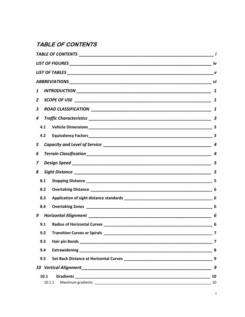
TABLE OF CONTENTS ________________________________________________________ i
LIST OF FIGURES ___________________________________________________________ iv
LIST OF TABLES _____________________________________________________________ v
ABBREVIATIONS ___________________________________________________________ vi
1 INTRODUCTION ________________________________________________________ 1
2 SCOPE OF USE _________________________________________________________ 1
3 ROAD CLASSIFICATION __________________________________________________ 1
4 Traffic Characteristics ___________________________________________________ 3
4.1 Vehicle Dimensions ________________________________________________________ 3
4.2 Equivalency Factors ________________________________________________________ 3
5 Capacity and Level of Service _____________________________________________ 4
6 Terrain Classification ____________________________________________________ 4
7 Design Speed __________________________________________________________ 5
8 Sight Distance _________________________________________________________ 5
8.1 Stopping Distance _________________________________________________________ 5
8.2 Overtaking Distance _______________________________________________________ 6
8.3 Application of sight distance standards ________________________________________ 6
8.4 Overtaking Zones _________________________________________________________ 6
9 Horizontal Alignment ___________________________________________________ 6
9.1 Radius of Horizontal Curves _________________________________________________ 6
9.2 Transition Curves or Spirals _________________________________________________ 7
9.3 Hair pin Bends ____________________________________________________________ 7
9.4 Extrawidening ____________________________________________________________ 8
9.5 Set-Back Distance at Horizontal Curves ________________________________________ 9
10 Vertical Alignment ______________________________________________________ 9
10.1 Gradients _____________________________________________________________ 10
10.1.1 Maximum gradients ___________________________________________________________ 10

ii
10.1.2 Grade Compensations __________________________________________________________ 10
10.1.3 Maximum (critical) Length of Grade _______________________________________________ 10
10.2 Climbing Lanes _________________________________________________________ 10
10.3 Emergency escape ramps ________________________________________________ 11
10.4 Vertical Curves _________________________________________________________ 12
10.4.1 Summit Curves ________________________________________________________________ 13
10.4.2 Valley Curves _________________________________________________________________ 14
11 Road Cross Section Elements _____________________________________________ 15
11.1 Carriageway ___________________________________________________________ 15
11.2 Shoulder ______________________________________________________________ 16
11.3 Medians ______________________________________________________________ 16
11.4 Formation or Roadway Width _____________________________________________ 17
11.5 Camber _______________________________________________________________ 17
11.6 Superelevation _________________________________________________________ 17
11.7 Side slopes ____________________________________________________________ 18
11.8 Typical Cross Sections ___________________________________________________ 19
11.9 Right of Way and Clearances ______________________________________________ 20
11.9.1 Right Of Way _________________________________________________________________ 20
11.9.2 Lateral clearances _____________________________________________________________ 20
11.9.3 Vertical clearances_____________________________________________________________ 21
12 Traffic Signs and safety _________________________________________________ 21
13 Miscellaneous Road Appertuances ________________________________________ 21
13.1 Guard Rails and Safety Barriers ____________________________________________ 21
13.2 Road Humps ___________________________________________________________ 22
13.3 Bicycle Tracks __________________________________________________________ 23
13.4 Pedestrian Facilities _____________________________________________________ 23
13.4.1 Footpaths ____________________________________________________________________ 23
13.4.2 Pedestrian Crossings ___________________________________________________________ 24
13.5 Bus Lay Bys ____________________________________________________________ 24
13.6 Curbs ________________________________________________________________ 25
13.7 Road Lighting __________________________________________________________ 26
13.8 Road Drainage _________________________________________________________ 26
14 Access Control ________________________________________________________ 27
iii
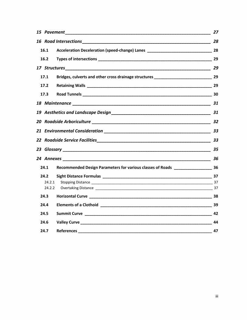
15 Pavement ____________________________________________________________ 27
16 Road Intersections _____________________________________________________ 28
16.1 Acceleration Deceleration (speed-change) Lanes _____________________________ 28
16.2 Types of intersections ___________________________________________________ 29
17 Structures ____________________________________________________________ 29
17.1 Bridges, culverts and other cross drainage structures __________________________ 29
17.2 Retaining Walls ________________________________________________________ 29
17.3 Road Tunnels __________________________________________________________ 30
18 Maintenance _________________________________________________________ 31
19 Aesthetics and Landscape Design _________________________________________ 31
20 Roadside Arboriculture _________________________________________________ 32
21 Environmental Consideration ____________________________________________ 33
22 Roadside Service Facilities _______________________________________________ 33
23 Glossary _____________________________________________________________ 35
24 Annexes _____________________________________________________________ 36
24.1 Recommended Design Parameters for various classes of Roads _________________ 36
24.2 Sight Distance Formulas _________________________________________________ 37
24.2.1 Stopping Distance _____________________________________________________________ 37
24.2.2 Overtaking Distance ___________________________________________________________ 37
24.3 Horizontal Curve _______________________________________________________ 38
24.4 Elements of a Clothoid __________________________________________________ 39
24.5 Summit Curve _________________________________________________________ 42
24.6 Valley Curve ___________________________________________________________ 44
24.7 References ____________________________________________________________ 47

iv
LIST OF FIGURES
Figure 9-1 Set Back Distance ................................................................................................................. 9
Figure 10-1: Emergency Escape Ramp ............................................................................................... 12
Figure 11-1: Road sections .................................................................................................................. 20
Figure 13-1: Safety Barriers ................................................................................................................. 22
Figure 13-2 Road Hump ....................................................................................................................... 23
Figure 13-3 :Bus Lay Bys Plan ............................................................................................................. 25
Figure 13-4 Typical curb designs ......................................................................................................... 25
Figure 16-1: Deceleration(a) and Acceleration(b) Lanes ..................................................................... 28
Figure 16-2: Intersection type selection ............................................................................................... 29
Figure 17-1Typical tunnel clearances................................................................................................... 31
Figure 24-1: Elements of a transition or spiral curve ............................................................................ 40
Figure 24-2: Summit Curve .................................................................................................................. 42
Figure 24-3: Minimum Length of Summit Vertical curve ...................................................................... 44
Figure 24-4: Valley Curve from headlight illumination criteria .............................................................. 45
Figure 24-5:Minimum Length of Valley Curve ...................................................................................... 46

v
LIST OF TABLES
Table 3-1 :Approximate Correlation between administrative and functional classification .................... 3
Table 4-1 Vehicle types, Equivalency Factors ....................................................................................... 4
Table 5-1:Capacity of Roads, PCU/day ................................................................................................. 4
Table 6-1 Terrain Classification .............................................................................................................. 5
Table 7-1 Design Speeds, km/h ............................................................................................................. 5
Table 8-1: Stopping distance .................................................................................................................. 5
Table 8-2: Overtaking distance ............................................................................................................... 6
Table 9-1 Minimum radius of horizontal curves ...................................................................................... 7
Table 9-2 Length of Transition Curves ................................................................................................... 7
Table 9-3 Hair Pin bends design parametres ......................................................................................... 8
Table 9-4 Extrawidening on curves ........................................................................................................ 8
Table 10-1: Maximum gradients ........................................................................................................... 10
Table 10-2: Maximum(critical) length of gradient ................................................................................. 10
Table 10-3: Minimum value of K for summit curves ............................................................................. 14
Table 10-4: Minimum value of K for valley curves ................................................................................ 15
Table 11-1Width of Carriageways, m ................................................................................................... 16
Table 11-2 Width of Shoulders, m ........................................................................................................ 16
Table 11-3 Camber, % ......................................................................................................................... 17
Table 11-4: Embankment Side Slopes ................................................................................................. 18
Table 11-5 Cuttings side slopes ........................................................................................................... 18
Table 11-6: Right of way ....................................................................................................................... 20
Table 11-7 Vertical Clearances for Electric wires and cables .............................................................. 21
Table 13-1: Width of footpath ............................................................................................................... 24
Table 13-2 : Return periods for calculating design discharges ............................................................ 26
Table 13-3 Type of lining of side drains ............................................................................................... 27
Table 16-1: Length of acceleration, deceleration lanes and tapers ..................................................... 28
Table 24-1 Recommended design Parameters .................................................................................... 36
Table 24-2 : Coefficient of longitudinal friction ..................................................................................... 37
Table 24-3 :Overtaking Distance Calculations ..................................................................................... 38
Table 24-4 : Coefficient of lateral friction .............................................................................................. 39

vi
ABBREVIATIONS
AASHTO- Association of American State Highway and Transportation Officials.
AADT-Average Annual Daily Traffic
ADT-Average Daily Traffic
B.S.-Bikram Sambat
CE-Common Era
DOLIDAR-Department of Local Infrastructure Development and Agricultural Roads
DOR-Department of Roads
h-hour
IP-Intersection Point
IRC-Indian Roads Congress
km-kilometre
LOS-Level of Service
LRN-Local roads network
m-metre
NRS-Nepal Roads Standards
ORN-Overseas Road Notes
PCU-Passenger Car Unit
s-second
SRN-Strategic Roads Network

1
1 INTRODUCTION
a. Nepal Road Standards -2027(Second Revision 2070), in short called NRS-2070, shall apply
to all Strategic Roads in rural areas being constructed within Nepal. For non-strategic (Local
Roads) and urban roads separate standards shall be considered.
b. With the objectives of achieving consistency in road design and construction, NRS was first
introduced by DOR in B.S. 2027 (1970 CE) and was revised in B.S 2045 (1988 CE).Minor
revisions were made in B.S 2051 (1994 CE) and in 1997 CE to incorporate certain changes,
which were relevant at the time of revisions. But those revisions were treated separately, not
as an official version of the NRS-2027.
c. Based on NRS (2027), standard design for roads and bridges including typical drawings were
prepared in 1978 CE. They are being used till now. The standard design prepared in 1978 CE
was based on the standard code of practice of that time.
d. Since then, there have been several revisions in design standards and specifications in Nepal
and also vast advancement in design and construction technology have occurred.
e. In the past, roads have been designed and constructed using either DOR standard guidelines
or using the design standard adopted by various aid agencies or consultants.
f. Due to non-uniformity in design and construction of roads and bridges, DOR has been facing
difficulties in maintenance and management of roads and bridges.
g. In this context and as demanded by the modern technological development, there is a need to
revise NRS-2027 and this is the second official revision.
2 SCOPE OF USE
a. These standards are to be applied for all roads being constructed in Nepal. These standards
apply mostly for non-urban roads (in open country outside built-up area.)
b. These requirements can be relaxed in some very difficult situations by the Government of
Nepal.
c. Efforts in general should, however, be to aim at standards higher than the minimum indicated
here.
d. The geometric features of roads except cross sectional elements do not lend to stage
construction. Geometric deficiencies are costly and sometimes impossible to rectify later on
due to subsequent road development. Therefore, it is essential that geometric requirements
should be kept in view right in the beginning.
3 ROAD CLASSIFICATION
Roads in Nepal are classified as follows:
A. Administrative Classification
Administrative classification of roads is intended for assigning national importance and level
of government responsible for overall management and methods of financing. According to
this classification roads are classified into:
National Highways
Feeder Roads
District Roads and
Urban Roads
2
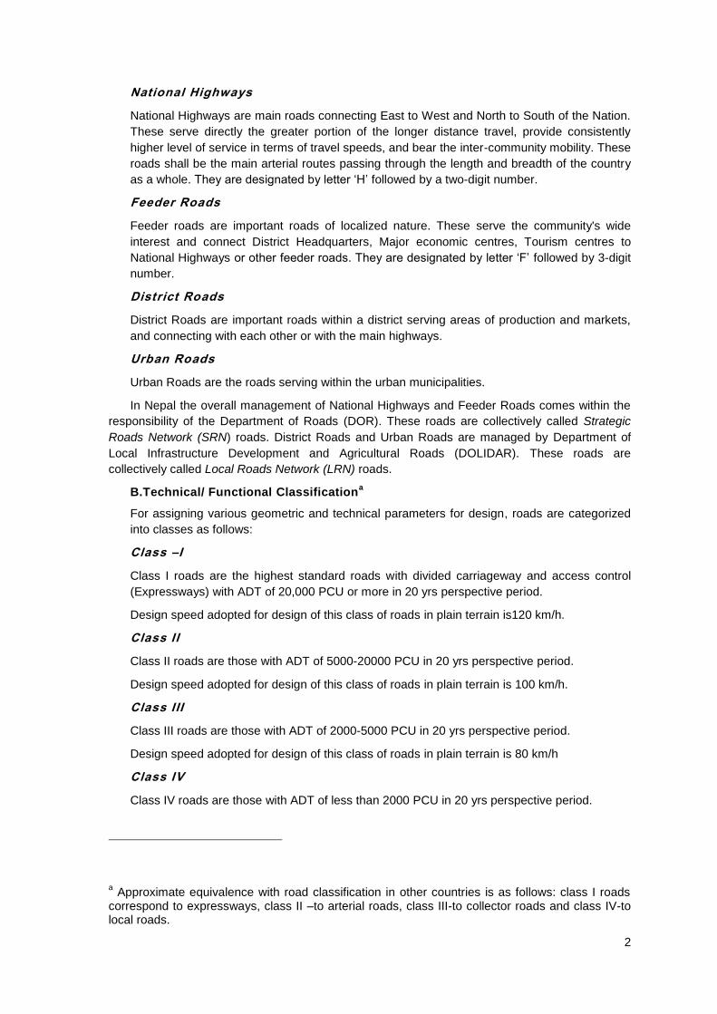
National Highways
National Highways are main roads connecting East to West and North to South of the Nation.
These serve directly the greater portion of the longer distance travel, provide consistently
higher level of service in terms of travel speeds, and bear the inter-community mobility. These
roads shall be the main arterial routes passing through the length and breadth of the country
as a whole. They are designated by letter „H‟ followed by a two-digit number.
Feeder Roads
Feeder roads are important roads of localized nature. These serve the community's wide
interest and connect District Headquarters, Major economic centres, Tourism centres to
National Highways or other feeder roads. They are designated by letter „F‟ followed by 3-digit
number.
District Roads
District Roads are important roads within a district serving areas of production and markets,
and connecting with each other or with the main highways.
Urban Roads
Urban Roads are the roads serving within the urban municipalities.
In Nepal the overall management of National Highways and Feeder Roads comes within the
responsibility of the Department of Roads (DOR). These roads are collectively called Strategic
Roads Network (SRN) roads. District Roads and Urban Roads are managed by Department of
Local Infrastructure Development and Agricultural Roads (DOLIDAR). These roads are
collectively called Local Roads Network (LRN) roads.
B.Technical/ Functional Classificationa
For assigning various geometric and technical parameters for design, roads are categorized
into classes as follows:
Class –I
Class I roads are the highest standard roads with divided carriageway and access control
(Expressways) with ADT of 20,000 PCU or more in 20 yrs perspective period.
Design speed adopted for design of this class of roads in plain terrain is120 km/h.
Class II
Class II roads are those with ADT of 5000-20000 PCU in 20 yrs perspective period.
Design speed adopted for design of this class of roads in plain terrain is 100 km/h.
Class III
Class III roads are those with ADT of 2000-5000 PCU in 20 yrs perspective period.
Design speed adopted for design of this class of roads in plain terrain is 80 km/h
Class IV
Class IV roads are those with ADT of less than 2000 PCU in 20 yrs perspective period.
a Approximate equivalence with road classification in other countries is as follows: class I roads
correspond to expressways, class II –to arterial roads, class III-to collector roads and class IV-to local roads.

3
Design speed adopted for design of this class of roads in plain terrain is 60 km/h
Design parameters for various classes of roads are given in Table 24-1.
For the design of roads the class of the road is taken as the basic deciding factor, which is
ascertained based on the traffic volume on the road. But an approximate correlation can be
established between the administrative and functional classifications of the roads as follows in
Table 3-1.
Table 3-1 :Approximate Correlation between administrative and functional classification
Plain and Rolling terrain Mountainous and steep terrain
National Highway I,II II,III
Feeder Roads II,III III,IV
4 TRAFFIC CHARACTERISTICS
4.1 Vehicle Dimensions
The maximum dimensions of vehicles considered for design of roads in Nepal are as follows:
Maximum Width, m 2.50
Maximum Height, m 4.75
Maximum Length, m 18.00
Maximum single axle load, kN 100
4.2 Equivalency Factors
a. It is not feasible to improve the standard of a road by very small increments and it is a
standard practice to design and construct new roads and improvement works to withstand the
estimated traffic at some future date.
b. In Nepal this forward period (perspective period) shall be 20 years, i.e. roads shall be
designed with a capacity sufficient to cater for the estimated traffic volume 20 years after the
date of completion of the works.
c. Different types of vehicles take up differing amounts of road space and have different
speeds(For geometric design) and impose differing loads on the road structure(For structural
design).
d. It is, therefore, necessary to adopt a standard traffic unit to which other types of vehicles may
be related.
e. For geometric design of roads this standard is the 'Passenger Car Unit (PCU)' which is that of
a normal car (passenger car), light van or pick-up. Other types of vehicles are taken into
account by multiplying by the following equivalency factors.

4
Table 4-1 Vehicle types, Equivalency Factors
SN Vehicle Type Equivalency Factor
4 Bicycle,Motorcycle 0.5
1 Car, Auto Rickshaw, SUV,Light Van
and Pick Up 1.0
2 Light (Mini) Truck, Tractor, Rickshaw 1.5
3 Truck,Bus,Minibus,Tractor with trailer 3.0
5 Non-motorized carts 6
5 CAPACITY AND LEVEL OF SERVICE
a. Among six Levels of Services (LOS) viz. „A‟ to „F‟ it is recommended to adopt a LOS „B‟ for
the design capacity of roads.
b. Under this condition, traffic will experience congestion and inconvenience during some of the
peak hours, which may be acceptable.
c. Design capacity governs the number of lanes required for the design volume of traffic.
d. At the level of service B, volume of traffic will be around 45 percent of maximum capacity
under mixed traffic condition. Design traffic volume should be taken as the volume at the end
of the design life considering the equivalency factors as shown in Table 4-1.
e. Recommended design service volumes for single lane, intermediate lane, two lane and multi
lane roads are presented in Table 5-1
Table 5-1:Capacity of Roads, PCU/day
S.
No. Category
Plain Rolling Mountainous
and steep
Low
curvature
(0-50
deg/km)
High
curvatur
e (>50
deg/km)
Low
curvatur
e(0-100
deg/km)
High
curvatur
e(>100
deg/km)
Low
curvatur
e(0-200
deg/km)
High
curvatur
e(>200
deg/km)
1 Single Lane Road(3.75 m) with good
quality shoulders at least 1.0m wide
2000 1900 1800 1700 1600 1400
2 Intermediate lane Road(5.5m) with
good quality shoulders at least 1.0m
wide
6000 5800 5700 5600 5200 4500
3 Double lane Road(7.0m) with good
quality shoulders at least 1.0m wide
15000 12500 11000 10000 7000 5000
4 Four lane road with a minimum 3.m
wide median
40000 35000 32500 30000 25000 20000
6 TERRAIN CLASSIFICATION
a. Geometric design of roads depends significantly on the terrain conditions. Economy in the
design usually dictates to change standards to suit the terrain.
5
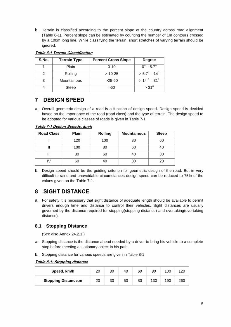
b. Terrain is classified according to the percent slope of the country across road alignment
(Table 6-1). Percent slope can be estimated by counting the number of 1m contours crossed
by a 100m long line. While classifying the terrain, short stretches of varying terrain should be
ignored.
Table 6-1 Terrain Classification
S.No. Terrain Type Percent Cross Slope Degree
1 Plain 0-10 0o – 5.7
o
2 Rolling > 10-25 > 5.7o – 14
o
3 Mountainous >25-60 > 14 o – 31
o
4 Steep >60 > 31o
7 DESIGN SPEED
a. Overall geometric design of a road is a function of design speed. Design speed is decided
based on the importance of the road (road class) and the type of terrain. The design speed to
be adopted for various classes of roads is given in Table 7-1
Table 7-1 Design Speeds, km/h
Road Class Plain Rolling Mountainous Steep
I 120 100 80 60
II 100 80 60 40
III 80 60 40 30
IV 60 40 30 20
b. Design speed should be the guiding criterion for geometric design of the road. But in very
difficult terrains and unavoidable circumstances design speed can be reduced to 75% of the
values given on the Table 7-1.
8 SIGHT DISTANCE
a. For safety it is necessary that sight distance of adequate length should be available to permit
drivers enough time and distance to control their vehicles. Sight distances are usually
governed by the distance required for stopping(stopping distance) and overtaking(overtaking
distance).
8.1 Stopping Distance
(See also Annex 24.2.1 )
a. Stopping distance is the distance ahead needed by a driver to bring his vehicle to a complete
stop before meeting a stationary object in his path.
b. Stopping distance for various speeds are given in Table 8-1
Table 8-1: Stopping distance
Speed, km/h 20 30 40 60 80 100 120
Stopping Distance,m 20 30 50 80 130 190 260

6
8.2 Overtaking Distance
(See also Annex 24.2.2)
a. Overtaking distance is the minimum distance that should be available to the driver to overtake
another vehicle safely. Overtaking distances for various design speeds are given in Table 8-2
Table 8-2: Overtaking distance
Speed, km/h 40 60 80 100 120
Minimum Overtaking Distance,m 165 300 470 640 880
8.3 Application of sight distance standards
a. Normally attempts should be made to provide a sight distance equal to the overtaking
distance in as much length of the road as possible. Where this is not feasible a sight distance
equal to twice the stopping distance should be made available.
b. In no case should the visibility of the road ahead be less than stopping distance for multi lane
roads(>=2 lanes) and twice the stopping distance for single lane roads.
c. It is always recommended to provide visibility of road ahead to as much distance as possible.
d. For calculating the visibility of the road the driver‟s eye is assumed to be located at 1.2m
above the road surface and any object lying on the roads surface to be 0.15m high.
8.4 Overtaking Zones
a. In stretches of roads where sufficient overtaking sight distance cannot be provided or on
single lane roads where overtaking or crossing opportunity is not available, overtaking or
passing zones shall be provided.
b. The width of the overtaking zone shall be the same as that of a minimum two lane road.
c. Length of the overtaking zone shall be at least 3 times the overtaking distance on two and
more lane roads.
d. On single lane roads length of passing zones shall be at least 2 times the overtaking sight
distance.
e. On single lane roads overtaking/passing lanes should be provided at not more than 1km
interval.
f. The start and end of overtaking zone shall be well informed by placing appropriate signs at
least stopping distance before the start and end of the zone.
9 HORIZONTAL ALIGNMENT
9.1 Radius of Horizontal Curves
(see also annex 24.2.2)
a. Minimum recommended values of radius of horizontal curves for various design speeds are
given below. However as far as site conditions permit largest possible values of radius should
be used.
7
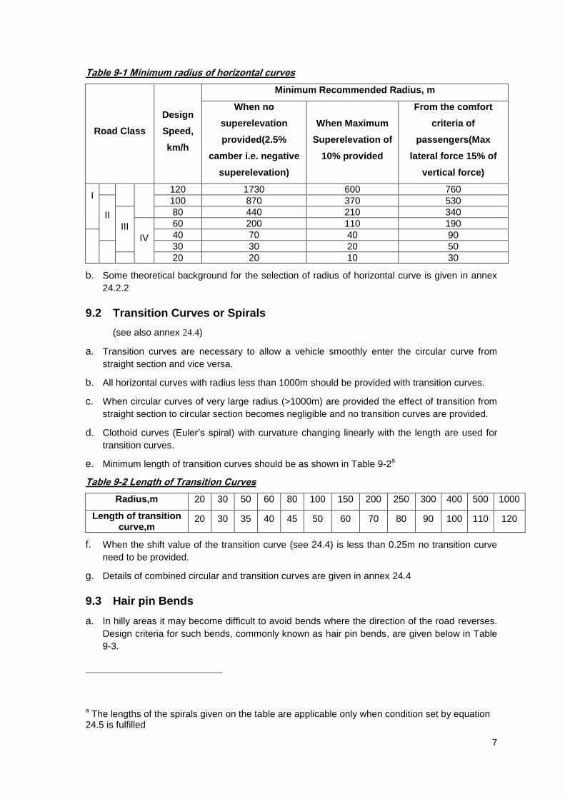
Table 9-1 Minimum radius of horizontal curves
Road Class
Design
Speed,
km/h
Minimum Recommended Radius, m
When no
superelevation
provided(2.5%
camber i.e. negative
superelevation)
When Maximum
Superelevation of
10% provided
From the comfort
criteria of
passengers(Max
lateral force 15% of
vertical force)
I
120 1730 600 760
II
100 870 370 530
III
80 440 210 340
IV
60 200 110 190
40 70 40 90
30 30 20 50
20 20 10 30
b. Some theoretical background for the selection of radius of horizontal curve is given in annex
24.2.2
9.2 Transition Curves or Spirals
(see also annex 24.4)
a. Transition curves are necessary to allow a vehicle smoothly enter the circular curve from
straight section and vice versa.
b. All horizontal curves with radius less than 1000m should be provided with transition curves.
c. When circular curves of very large radius (>1000m) are provided the effect of transition from
straight section to circular section becomes negligible and no transition curves are provided.
d. Clothoid curves (Euler‟s spiral) with curvature changing linearly with the length are used for
transition curves.
e. Minimum length of transition curves should be as shown in Table 9-2a
Table 9-2 Length of Transition Curves
Radius,m 20 30 50 60 80 100 150 200 250 300 400 500 1000
Length of transition curve,m
20 30 35 40 45 50 60 70 80 90 100 110 120
f. When the shift value of the transition curve (see 24.4) is less than 0.25m no transition curve
need to be provided.
g. Details of combined circular and transition curves are given in annex 24.4
9.3 Hair pin Bends
a. In hilly areas it may become difficult to avoid bends where the direction of the road reverses.
Design criteria for such bends, commonly known as hair pin bends, are given below in Table
9-3.
a The lengths of the spirals given on the table are applicable only when condition set by equation
24.5 is fulfilled

8
Table 9-3 Hair Pin bends design parametres
Minimum design speed 20km/h
Minimum Radius of curvature 15m
Minimum length of transition curve 15m
Maximum longitudinal gradient 4%
Maximum superelevation 10%
b. A minimum distance of 60m should be provided between successive bends of consecutive
hair pin bends.
c. At hair pin bends it is preferable to pave the road to the full width of the roadway.
9.4 Extrawidening
a. When a vehicle negotiates a horizontal curve the rear wheels do not exactly follow the path of
the front wheels. Their path is shifted towards the centre of the curve in relation to the front
wheels‟ path.
b. In curves the drivers of the vehicles have a tendency to keep a greater clearance between
them as compared to the straight sections of the road.
c. For the reasons mentioned above the width of carriageway of roads at the curves is made
wider than on the straight sections.
d. Value of extrawidening is adopted as shown below in Table 9-4
Table 9-4 Extrawidening on curves
Radius of curve,m
20 20-40 40-60 60-100 100-300 >300
Extra width,m
Single lane road
0.9 0.6 0.6 Nil Nil Nil
Double lane road
1.5 1.5 1.2 0.9 0.6 Nil
Multi lane(n-lane) road
0.75n 0.75n 0.6n 0.45n 0.3n Nil
e. Extrawidening should be introduced gradually at an approximately uniform rate along the
transition curve. On curves having no transition two third of it should be attained before the
start of the circular curve and one third on the curve.
f. Extrawidening shall be applied on both sides of the carriageway, except that on hill roads it
will be preferable if the entire widening is done only on the inside. Similarly, the widening
should be provided only on the inside when the curve is plain circular and has no transition
curve.

9
9.5 Set-Back Distance at Horizontal Curves
a. Adequate sight distance should be available across the inside of horizontal curves. Distance
from the road centre line within which the obstructions should be cleared to ensure the
needed visibility i.e. the “ set-back distance”, can be calculated from geometrical
considerations as shown in Figure 9-1
b. The set-back distance is calculated as follows:
cos)( nRRm ... ... ... ... ... ... ... 9-1
Where,
radiansnR
S
)(2
m-minimum set-back distance to sight obstruction in metres(measured from the centre line of
the road)
R-radius at the centre line of the road in metres
n-distance between the centre line of the road and the centre line of the inside lane in metres
S-sight distance in metres(measured along the centre line of the road)
Figure 9-1 Set Back Distance
10 VERTICAL ALIGNMENT
a. The vertical alignment of the road should provide for a smooth longitudinal profile without any
kinks and visual discontinuities in the profile. Grade changes in vertical alignments should be
as less frequent as possible.

10
10.1 Gradients
10.1.1 Maximum gradients
a. Vehicle operation cost is directly related with the longitudinal gradients, and so it is
recommended to adopt their values as small as possible.
b. Right from the early stage of alignment fixing, it should be born in mind that it becomes very
difficult to flatten the gradient at later stage.
c. Maximum gradient depends on the dynamic characteristics of commercial trucks, design
speed and maximum allowable reduction in speed during climbing up the gradient.
d. Considering these factors (weight to power ratio of trucks-120kg/kW, with a maximum
reduction of speed by 25 kmph below the design speed) maximum gradients for various
design speeds shall be as follows:
Table 10-1: Maximum gradients
Design Speed, km/h 20 30 40 60 80 100 120
Maximum Gradient,% 12 10 9 7 6 5 4
e. Minimum longitudinal gradients for longitudinal drainage purpose is 0.5%
10.1.2 Grade Compensations
a. Maximum value of longitudinal gradient shall be eased by 0.5% for each rise of 500m above
mean sea level.
b. Due to loss of tractive efforts of the vehicle on curves it is recommended to ease the gradients
by an amount calculated as follows:
Grade compensation (%)= R
R30... ... ... ... ... ... ... 10-1
subject to a maximum of 75/R, where R-radius in m.
c. It is not necessary to compensate grades below 4%.
10.1.3 Maximum (critical) Length of Grade
a. Maximum length of road with a gradient should be limited to the following values:
Table 10-2: Maximum(critical) length of gradient
Gradient,% 4 5 6 7 9 10 12
Maximum(critical) Length,m
600 450 400 300 200 150 150
10.2 Climbing Lanes
a. Climbing lanes are provided on road upgrades for slow moving heavy vehicles to allow drivers
of light vehicles to move without reducing speed when they encounter slow moving heavy
vehicles.
b. Climbing lanes are to be provided if the length of the grade is such that a speed reduction of
more than 25kmph of fast moving vehicle occurs(see Table 10-2)

11
c. Climbing lanes are provided if the upgrade traffic flow is greater than 200 veh/hr and the
upgrade truck flow is higher than 20 veh/hr(in addition to the critical length requirements of
above(b)).
d. Climbing lanes are generally not necessary on low traffic multilane highways.
e. Width of climbing lanes should be minimum 3.5m.Length should be such that these lanes
start at least 50m before the upgrade starts and should continue at least 100 m beyond it.
10.3 Emergency escape ramps
a. Emergency escape ramps are to be provided on long downgrade of a highway for use by
trucks that have lost control and cannot slow down. They are more effective if there is a
horizontal curve on long downgrade stretch.
b. The escape ramps should be made of sandpiles or loose aggregates with upwards gradients.
Length of the emergency ramp is found by following formula:
)(254
2
iF
VL
... ... ... ... ... ... ... 10-2
Where,
V-speed at the entrance, km/h
i -percent grade divided by 100
Fa-rolling resistance, expressed as equivalent percent gradient divided by 100
c. The alignment of the escape ramp should be tangent or on very flat curvature to minimize the
driver‟s difficulty in controlling the vehicle.
d. Width of the ramp should be 3.5 m minimum.
a Value of F depends on the rolling resistance of the piling material of the escape ramp. It should
be found by actual testing.

12
Figure 10-1: Emergency Escape Ramp
10.4 Vertical Curves
a. When two straight sections of a road in longitudinal profile meet at a point, vertical curves are
provided for smooth travel along the road.
b. The type of vertical curves is selected in such a way that the rate of change of grade
throughout the curve is uniform.
c. A quadratic parabola satisfies the above condition and should be used for vertical curves
design.
d. If the convexity of the curve is upwards it is called a summit curve otherwise a valley curve.

13
e. Design of vertical curve is controlled by K-valuea and length of the curve (L-value).
K and L are related as follows:
A
LK ... ... ... ... ... ... ... 10-3
Where,
K-maximum radius of curvature i.e. curvature at the vertex of the parabola of the vertical
curve divided by 100, m/%.
L-Length of the vertical curve,m
A- algebraic difference of longitudinal grades of the vertical alignment,%
10.4.1 Summit Curves
(see also annex 24.5)
a. Minimum length of summit curve L is to be found from the consideration of providing a sight
distance(S) throughout the curve equal to stopping distance(Table 8-1) or overtaking
distance(Table 8-2) whichever gives the higher value.
b. From the consideration of providing sight distance equal to stopping distance the height of
driver‟s eye and the object are taken as 1.2m and 0.15m above pavement surface
respectively.
When sight distance(S) is less than L
440
2ASL ... ... ... ... ... ... ... 10-4
In this case
440
2SK ... ... ... ... ... ... ... 10-5
When sight distance(S) is more than L
ASL
4402 ... ... ... ... ... ... ... 10-6
Where,
L-Length of summit curve ,m
A-Algebraic difference in approach grades,%
S- sight distance taken equal to the stopping distance, m
c. From the consideration of providing sight distance equal to the overtaking distance or twice
the stopping distance for single lane road (whichever is higher) with the height of driver‟s eye
1.2 m above pavement surface.
When sight distance (S) is less than L
a The physical meaning of K-value is the length of vertical curve per unit algebraic difference of
grades. It gives the minimum radius (i.e. radius at the vertex) of parabola if algebraic difference of grades is expressed in absolute value and not in %.

14
960
2ASL ... ... ... ... ... ... ... 10-7
In this case
960
2SK ... ... ... ... ... ... ... 10-8
When sight distance (S) is more than L
ASL
9602 ... ... ... ... ... ... ... 10-9
Where,
L-Length of summit curve ,m
A-Algebraic difference in approach grades,%
S-overtaking distance or twice the stopping distance (whichever gives greater value), m
d. Higher of the values from (b) and (c) above should be taken for design.
e. Minimum length of the summit vertical curves should be taken from the graph on Figure 24-3.
f. It is easier to design vertical summit curve based on the K-value since it takes values of both
L and A into consideration (K=L/A). Minimum value of K for various design speeds are given
below in Table 10-3.
g. When the change of grade at vertical curve is very small it is always better to provide a
vertical curve as per the following table than not to provide at all.
Table 10-3: Minimum value of K for summit curves
Design Speed,km/h 20 30 40 60 80 100 120
K,m/% 2 4 29 94 231 427 807
10.4.2 Valley Curves
(see also annex 24.6)
a. The length (L) and K-value of vertical valley curve should be selected based on the required
night visibility by the headlight of the vehicle of at least stopping distance as given on Table
8-1 or based on the riding comfort of the passengers and overloading on the suspension
system of the automobile.
b. Minimum length of valley curve (L) from the consideration of night visibility of road surface by
the illumination by the head light is to be found as follows(taking 0.75m as height of mounting
of head light above pavement surface, and 2o as the angle of illumination of the headlight):
When stopping distance(S) is less than L
S
ASL
5.3150
2
... ... ... ... ... ... ... 10-10
In this case

15
S
SK
5.3150
2
... ... ... ... ... ... ... 10-11
When stopping distance(S) is more than L
A
SSL
5.31502
... ... ... ... ... ... ... 10-12
Where,
L-Length of valley curve ,m
A-Algebraic difference in approach grades,%
S-stopping distance, m
c. Minimum length of valley curve (L) from the consideration of the riding comfort of the
passengers and overloading on the suspension system of the automobile is found as follows:
390
2AVL ... ... ... ... ... ... ... 10-13
390
2VK ... ... ... ... ... ... ... 10-14
Where,
L-Length of valley curve ,m
A-Algebraic difference in approach grades,%
V-design speed in km/h
d. Higher of the values from (b) and (c) are to be adopted in the design.
e. Minimum length of the valley vertical curves should be taken from the graph on Figure 24-5.
f. As in the case of summit curve minimum value of K for valley curves for various design
speeds are given below in Table 10-4
g. When the change of grade at vertical curve is very small it is always better to provide a
vertical curve as per the following table than not to provide at all.
Table 10-4: Minimum value of K for valley curves
Design Speed,km/h
20 30 40 60 80 100 120
K,m/% 3 6 17 42 111 236 441
11 ROAD CROSS SECTION ELEMENTS
11.1 Carriageway
a. The standard width of carriageway shall be as shown on the following table. Total width of
pavement shall be determined based on the volume of the traffic and capacity of each lane as
given on art. 5.

16
Table 11-1Width of Carriageways, m
Single lane road Intermediate lane Multilane pavements width per
lane
3.75
(upto 3.0 m in difficult
terrain)
5.5 3.5
b. In case of single lane roads it is recommended to have two treated shoulders on either side to
make a total width of 5.5m of treated surface.
11.2 Shoulder
a. The width of shoulders on either side of the carriageway shall be at least 0.75m.
Recommended width of shoulder for various classes of roads is given below in Table 11-2.
b. For protection of pavement from water percolating under it from shoulder it is recommended
to treat at least a 0.50-0.75m wide strip of shoulder near the edge of the pavement with
impervious to water surfacing.
c. If a small gap(<1m) of untreated shoulder is formed between the edge of the pavement and
edge of the side drain in hill roads it is recommended to treat this gap with appropriate surface
treatment.
Table 11-2 Width of Shoulders, m
Road Class Class I Class II Class III Class IV
Minimum
shoulder width, m 3.75 2.5 2.0 1.5
d. For mountainous and steep terrains the above values can be reduced to a minimum value for
a lower class of the road but not less than 0.75m.
e. It is desirable that the color and texture of shoulders be different from those of the
carriageway.
f. This contrast serves to clearly define the carriage way at all times, particularly at night and
during inclement weather, while discouraging the use of shoulders as additional through
lanes.
g. Very wide shoulders (more than 3.75m wide) are also not desirable due to tendency of
vehicles misusing it as a carriageway.
11.3 Medians
a. For roads with 4 or more lanes, it is recommended to provide medians or traffic separators.
Medians should be as wide as possible.
b. A minimum median width of 5m is recommended. But a width of 3m can be adopted in areas
where land is restricted.
c. In mountainous and steep terrains maximum possible width of median dictated by the
topography should be provided. In such situations simple barriers may be provided to function
as a median or individual carriageways could be designed at different levels.
d. On long bridges and viaducts the width of the median may be reduced to 1.5m, but in no case
this should be less than 1.2m.

17
e. The median should be of uniform width in a particular section of the highway. However, where
changes are unavoidable, a transition of 1 in 20 must be provided.
11.4 Formation or Roadway Width
a. Formation width shall be a total of widths of carriageways, medians and shoulders as
discussed in previous paragraphs.
11.5 Camber
a. All straight sections of roads shall have a camber or crossfall as given on the Table 11-3.
b. On roads with undivided carriageways the camber shall be on both directions from the centre
line of the road. On roads with divided carriageways unidirectional camber can be provided.
c. However on some sections of hill roads with undivided carriageway a unidirectional camber
can be adopted. In this case the adverse effect of negative camber on movement of vehicles
on curves should be properly checked.
Table 11-3 Camber, %
Pavement type Cement Concrete Bituminous Gravel Earthen
Camber, % 1.5 to 2.0 2.5 4.0 5.0
d. On straight sections of roads, shoulders should have a higher crossfall than that of the
carriageway by 0.5%.
11.6 Superelevation
a. Superelevation is provided on horizontal curves. Value of superelevation is calculated using
following formula:
fR
Ve
127
2
... ... ... ... ... ... ... 11-1
Where,
e-value of superelevation, m/m
R-Radius of horizontal curve
V-Design Speed, km/h
f-co-efficient of lateral friction, depends on the vehicle speed and taken as in Table 24-4
b. Maximum superelevation to be provided is limited to:
In plain and rolling terrain 7%
In snow bound areas 7%
In hilly areas not bound by snows 10%
c. Minimum value of superelevation should be equal to the rate of camber of the pavement.
d. The rate of introduction of superelevation (i.e. longitudinal grade developed at the pavement
edge compared to through grade along the centre line) should be such as not to cause
discomfort to travelers or to make the road unsightly.
e. Rate of change of the outer edge of the pavement should not be steeper than 1 in 150 in plain
and rolling terrain and 1 in 60 in mountainous and steep terrain in comparison with the grade
of the centre line.

18
11.7 Side slopes
a. Side slopes of embankment and cuttings depend on the type of fill/cut materials and
height/depth of filling/cutting.
b. Recommended side slopes for embankments are given below. But wherever possible flatter
slopes are recommended for aesthetic reason and traffic safety.
Table 11-4: Embankment Side Slopes
Height, m Side Slope(vertical:horizontal)
<1.5 1:4
1.5-3.0 1:3
3.0-4.5 1:2.5
4.5-12.0 1:2
>12.0 Design specially
c. If natural cross slope of the ground is more than 1:5 then the ground should be cut with more
than 2m wide horizontal steps.
d. Recommended values of side slopes in cutting are given in Table 11-5
Table 11-5 Cuttings side slopes
Soil type Side Slope(vertical:horizontal)
Ordinary Soil 1:2 to 1:1
Disintegrated rock or conglomerate 1:1/2 to 1:
1/4
Soft rock, shale 1: 1/4 to 1:
1/8
Medium Rock 1: 1/12 to 1:
1/16
Hard Rock Almost vertical

19
11.8 Typical Cross Sections

20
Figure 11-1: Road sections
11.9 Right of Way and Clearances
11.9.1 Right Of Way
a. Right of way for different types of roads shall be as follows:
Table 11-6: Right of way
Road Type Total Right of Way,m
Highways 50
Feeder Roads 30
District Roads 20
11.9.2 Lateral clearances
a. For a single carriageway road that goes through an underpass, whole width of the roadway
(carriageway plus shoulder widths) should be cleared in lateral direction.
b. If footpaths are provided minimum lateral clearance should be width of footpath plus 1.0 m.

21
c. On roads with divided carriageway, left hand side lateral clearance should be as given on (a.)
and (b.) above.
d. Right hand side clearance should be 2.0 m (desirable) with 1.5m minimum.
11.9.3 Vertical clearances
e. A vertical clearance of 5.0m measured from the crown of the road surface shall be provided
for whole roadway width on all roads. No obstructions shall be made on this space.
f. Vertical clearance for high voltage electric cables from the road surface shall be as shown in
Table 11-7
Table 11-7 Vertical Clearances for Electric wires and cables
Voltage,kV Minimum Vertical Clearance,m
1 6
110 7
132 7.5
220 8
330 8.5
550 9
720 16
12 TRAFFIC SIGNS AND SAFETY
a. All traffic signs and road markings shall be as per the “Traffic Signs Manuals Vol-I and Vol II”
published by the DOR with amendments made thereafter. Road safety notes published by the
DOR shall be consulted.
13 MISCELLANEOUS ROAD APPERTUANCES
13.1 Guard Rails and Safety Barriers
a. Guard Rails and safety barriers are provided in places where serious damage to vehicle and
people may occur when an out of control vehicle may leave the roadway or hit other objects.
b. Road edge barriers are provided near the edge of the road with steep slopes (more than 1:4)
or there is a drop of more than 3m or on the outer edge of sharp horizontal curves to protect
the vehicles from falling off.
c. They are provided to protect the vehicle from hitting roadside objects e.g. overhead bridge
piers, large sign posts, large trees, walls, ends of bridge parapets located near the edge of
the carriageway.
d. Usually flexible type steel wire rope barriers or semi-rigid type steel beam barriers or rigid
type RCC barriers are used as barriers.
e. Median Barriers are provided along the edge of medians on divided highways to protect the
traffic on both carriageways to cross-over the median and prevent head-on collisions or hitting
other objects on the medians.
f. Road Safety Notes published by the Department of Roads should be consulted for selection
and installation of safety barriers.

22
Figure 13-1: Safety Barriers
13.2 Road Humps
a. No road humps shall be provided on road located in non urban areas. They can be provided
on slow speed roads (speed <30 kmph, only on class IV roads) on some urban areas if their
necessity is justified.
b. The width of the hump shall not be less than 3.7m.It should have a parabolic shape as shown
on the figure with maximum height of 0.1m at the crown.
c. The faces of the humps shall be painted with 200 mm wide alternating black and white stripes
at 45 deg slopes.

23
Figure 13-2 Road Hump
13.3 Bicycle Tracks
a. In all roads with ADT of more than 4000 PCU and movement of bicycles more than 1000
nos/day bicycle tracks should be constructed. The minimum width of each lane of the bicycle
track should be 1.2m for each direction of movement.
b. The track should be constructed on a separate formation or at least 1 m away from the edge
of the roadway.
13.4 Pedestrian Facilities
13.4.1 Footpaths
a. Provision of footpaths should be made on all roads passing through populated areas.
b. On high traffic non-urban roads footpaths should be constructed outside of the roadway on separate formation or buffer areas should be established so as to separate them from the carriage way.
c. Width of the footpath depends on the volume of anticipated pedestrian traffic. But a minimum
width of 1.5 m is required.
d. In case of narrow footpaths(<1.8m wide) a passing zone of a minimum width of 1.8m and
length of 2.0 m is to be provided at every 50m or less for passing of two wheelchairs.
e. The minimum width of footpaths for various volumes of pedestrian traffic should be as shown
in Table 13-1

24
Table 13-1: Width of footpath
Hourly Design Flow(bothways) of 15 min peak period
Footpath width,m
Upto 500 1.5
500-1500 2.0
1500-2500 2.5
2500-3500 3.0
13.4.2 Pedestrian Crossings
a. Grade separated pedestrian crossings should be provided where pedestrian volume, traffic
volume, intersection capacity, and other conditions favor their use, although their specific
location and design require individual study.
b. They may be warranted where there are heavy peak pedestrian movements, such as at
central business districts, factories, schools, or athletic fields, in combination with moderate to
heavy vehicular traffic or where unusual risk or inconvenience to pedestrians would otherwise
result.
c. Overpass/underpass crossings should be easier to use(than directly crossing the road), well
lighted to enhance the sense of security and well ventilated(especially on long underpasses).
d. Walkways for pedestrian separations should have a minimum width of 2.5 m. Greater widths
may be needed where there are exceptionally high volumes of pedestrian traffic.
e. Overpasses should have a minimum vertical clearance of 5.0m and underpasses 2.5m.
f. All overpass/underpass pedestrian crossings should be provided with ramp for wheelchairs or
other alternative measures (e.g. lifts) for comfortable movement of disabled people. Maximum
grade on the ramps should not be steeper than 8%.
13.5 Bus Lay Bys
a. To be fully effective, bus lay bys should incorporate
a deceleration lane or taper to permit easy entrance to the loading area,
a standing space sufficiently long to accommodate the maximum number of vehicles
expected to occupy the space at one time, and
a merging lane to enable easy reentry into the carriage way.
b. A taper of about 5:1, longitudinal to transverse, is a desirable minimum for deceleration lane
c. The standing space should provide about 15 m of length for each bus.
d. The width of standing space should be at least 3.0 m and preferably 3.75 m.
e. The merging or reentry taper may be somewhat more abrupt than the deceleration taper but,
preferably, should not be sharper than 3:1.
f. If bus lay bys are located near the intersections, it is preferable to locate them on departure
side(far side) of the intersection.

25
Figure 13-3 :Bus Lay Bys Plan
13.6 Curbs
a. Curbs are classified as “Barrier” or vertical type (with vertical road side face) and “Mountable”
or sloping type(with sloping roadside face).
b. The height of curbs ranges from 10 to 20 cm.
c. Barrier curbs are designed to discourage vehicles leaving the pavement. Mountable curbs are
provided at medians or channelizing islands.
d. Vertical curbs should not be used along freeways or other high-speed roads.
e. Design may vary in shape or size. But they should be good in appearance and strong.
f. Some recommended designs are shown in Figure 13-4
Figure 13-4 Typical curb designs

26
13.7 Road Lighting
a. Rural highways should be designed with an open cross section and horizontal and vertical
alignment of a fairly high type. Accordingly, they offer an opportunity for near maximum use of
vehicle headlights, resulting in reduced justification for fixed highway lighting.
b. Provision of artificial lighting should be made on all roads near populated areas, on major
bridges, bus stops, roads and railroads intersections (up to a distance of 250m from the point
of intersections), tunnels and approaches to them and toll plazas.
c. Light mounting poles should be at least 9m high(but mounting heights of 10 to 15 m are
usually preferable). They should be located outside the edge of the roadway or on wide
central medians.
d. Level of illumination should be 30 lux on important high speed roads and 15 lux on other main
roads.
e. The ratio of minimum to average illuminations should be about 0.4.
13.8 Road Drainage
a. For long life of pavement and other components of a highway system, the subgrade should
be kept at optimum moisture level and avoided to be over wetted.
b. Water should be drained away from the road and ground surface as well as under the surface
by a system of surface and subsurface drainage.
Surface Drainage
a. Water is drained from the road surface with adequate camber of both the carriageway and the
shoulder.
b. Road side drains are provided in all cut sections to remove water in the longitudinal direction.
c. Toe-of-slope road side drains are constructed in low fill(<0.8m filling height) sections to
convey water away to water courses
d. Intercepting or catch water drains are placed on back of the top of cut slopes to intercept
surface water. Distance of these drains from the edge of the cutting should not be less than
5m.
e. Flumes are provided to carry collected water down deep cuts or high fill slopes.
f. Drains should be provided with minimum 0.5% longitudinal grade.
g. Trapezoidal shape of drains is preferred.
h. For calculating design discharge on roadside drains following return periods should be taken.
Table 13-2 : Return periods for calculating design discharges
Road Class I and II III IV
Return Period in years
50 33 25
i. Outlets from the side drains should be provided at no more than 500m intervals.
j. Sides and bottoms of the drains should be lined according to the longitudinal slope of the
drain as shown in Table 13-3.Size of the drain should be worked out based on the discharge,
longitudinal slope and type of lining.

27
Table 13-3 Type of lining of side drains
Type of lining
Longitudinal slopes,%
Sandy Soil Clayey Soil
No lining required <1 <2
Grass turfing 1~3 2~3
Stone Rip Rap,masonry,concrete
3~5 3~5
Stepping >5 >5
Subsurface Drainage
a. Subsurface water table should always be kept 1 to 1.2 m below the subgrade level to protect
pavement layers from excessive moisture.
b. If it is difficult to achieve the above difference in levels, subsurface drains need to be
provided.
c. To save road subgrade from detrimental effects of moisture from the capillary rise of water a
layer of granular materials is provided between the subgrade and the highest level of
subsurface water.
d. Sometimes geotextiles are laid over the subgrade soil to stop the migration of small clay
particles upwards that increase the capillary rise of water to the pavement.
e. Subsurface drains are constructed with 150mm-200mm dia perforated pipes with well
designed filter material around them and subsequently wrapped by geotextile with adequate
longitudinal slopes. Numbers and spacing of subsurface drains should be decided by the
design.
14 ACCESS CONTROL
a. For smooth flow of traffic and reducing ribbon development on non-urban highways number of
accesses to it from side roads should be restricted.
b. No direct access is allowed on class I roads.
c. Access to private property from class II, III and IV roads should not be at less than 300m
interval.
d. If parallel service road (frontage road) is provided the connection from these roads to
highways should not be at less than 750m interval.
15 PAVEMENT
a. The selection of pavement type is determined based on the traffic volume and composition,
soil characteristics, weather, performance of pavements in the area, availability of materials,
energy conservation, initial cost, and the overall annual maintenance and service-life cost.
b. Pavement surface type provided should be consistent with the selected design speed for the
highway.
c. For selection and design of road pavements guidelines published by the Department of
Roads shall be followed.

28
16 ROAD INTERSECTIONS
16.1 Acceleration Deceleration (speed-change) Lanes
a. For facilitating change of speed by vehicles diverging from or merging into high speed roads
acceleration and deceleration lanes are provided.
b. Acceleration and Deceleration lanes are provided at intersections, at bus stops, at fueling and
servicing stations and at resting spots.
c. These lanes are provided when future traffic on them is expected to be more than ADT of
1000 PCU.
d. The width of these lanes is kept the same as the lane width of the highway.
e. At the place of merging and diverging these lanes are provided with taper.
Figure 16-1: Deceleration(a) and Acceleration(b) Lanes
f. Lengths of acceleration and deceleration lanes are kept equal to the distance required for the
vehicle to increase the speed from 20km/h to the design speed with an acceleration of 1m/s2
and reduce the speed from the design speed to a speed of 20km/h with a deceleration of
2m/s2 respectively.
g. Based on the above the length of acceleration and deceleration lanes and length of taper for
various design speed is given in Table 16-1
Table 16-1: Length of acceleration, deceleration lanes and tapers
Design Speed, km/h
Length of Accelerating
Lane,m
Length of decelerating
lanes,m
Length of taper,m
60 130 70 30
80 240 120 60
100 370 190 70
120 540 270 80

29
16.2 Types of intersections
a. Intersections may be at grade (roads crossing at the same level) or grade separated(roads
crossing at different levels).
b. Grade separated intersections with ramps are called interchanges. They may be simple
without any ramps.
c. Type of intersection depends on the volume of traffic on crossing roads and angle of crossing.
d. Intersection at grade is not allowed when one of the crossing roads is a class I road.
e. Roads should cross each other at right angle as far as possible
f. Approach sections of intersecting grades should not be steeper than 4%.
g. Detailed design for each intersection should be carried out separately.
h. For a general guidance following graph can be used to select the type of intersections.
Figure 16-2: Intersection type selection
17 STRUCTURES
17.1 Bridges, culverts and other cross drainage structures
a. Cross drainage structures having length of more than 6m are called bridges.
b. Other cross drainage structures are culverts, causeways (simple) and vented causeways.
c. These structures shall be designed and constructed as per Nepal Bridge Standards-2067 with
revisions, if any.
d. The full width for the approach roadway should be provided across all new bridges.
17.2 Retaining Walls
a. On steep cross slopes of hills, volume of filling may be considerably high and cutting slopes
are unstable.
b. To minimize the volume of fillings and to stabilize the slopes retaining walls are constructed.
ADT on main road,PCU
1. Simple intersection
2. With channelizing islands on secondary road
3. With channelizing islands on both roads
4. Grade separated intersections AD
T o
n s
eco
nd
ary
ro
ad
,PC
U
30
c. Retaining walls are designed to withstand the lateral pressure from the soil or the filling
materials so as to be stable against overturning, sliding, foundation failure due to excessive
bearing pressure with adequate structural strength.
d. Vehicle load is replaced by an equivalent surcharge of additional height of filling materials for
design.
e. When the height of retaining walls becomes large, overpass or half-bridges are constructed.
17.3 Road Tunnels
a. Although road tunnels are very costly, they are often constructed if after rigorous economic
analysis they substantially reduce the cost of construction, maintenance and vehicle operation
costs of roads especially on hilly areas.
b. Highway tunnels are usually constructed either by mining method or cut and cover method.
c. Tunnels are usually constructed with two lanes. In four lane roads two separate two lane
tunnels are constructed.
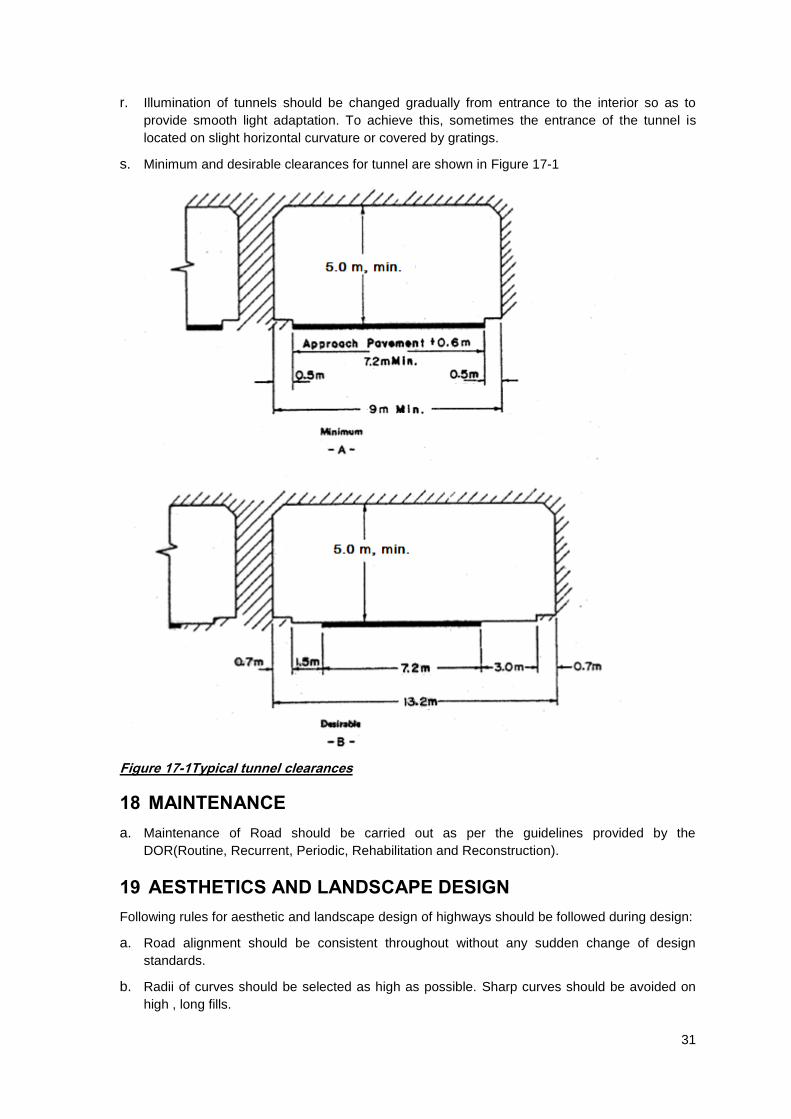
d. The minimum roadway width between curbs should be at least 0.6 m greater than the
approach carriageway, but not less than 7.2m.
e. The curb or sidewalk should be 0.5m minimum on either side of the pavement.
f. The total clearance between walls of a two lane tunnel should be a minimum of 9 m
g. Minimum vertical clearances inside the tunnels should be 5.0m.
h. Tunnels should be as shortest as possible.
i. As far as possible tunnels should be constructed with straight horizontal alignment which
simplifies the construction, reduces the cost and it is easy to provide adequate sight distance
on tunnels.
j. Vertical alignment of the tunnel should be decided based on the economic balance between
construction costs and operating and maintenance expenses.
k. Ventilation costs depend on length, grades, natural and vehicle-induced ventilation, type of
system, and air quality constraints.
l. Maximum gradient of the road in tunnels should be 4% and minimum 0.4%(From drainage
consideration)
m. Tunnels of length less than 300m are constructed with one directional gradient and more than
300 m with two way grades with maximum height at the centre.
n. Tunnels of more than 150m length should be provided with artificial ventilation.
o. Maximum speed of air inside the tunnels(without considering the motion of air due to
movement of vehicles) from artificial ventilation should be 6m/s.
p. Tunnels of more than 300m length on straight sections or 150m on curved sections of non-
urban roads or all tunnels on urban roads should be illuminated with artificial lighting.
q. Illumination of tunnels at the level of carriageway should not be less than:
30 lux at night
400-750 lux during day time near the portals and 30 lux at the middle.
31
r. Illumination of tunnels should be changed gradually from entrance to the interior so as to
provide smooth light adaptation. To achieve this, sometimes the entrance of the tunnel is
located on slight horizontal curvature or covered by gratings.
s. Minimum and desirable clearances for tunnel are shown in Figure 17-1
Figure 17-1Typical tunnel clearances
18 MAINTENANCE
a. Maintenance of Road should be carried out as per the guidelines provided by the
DOR(Routine, Recurrent, Periodic, Rehabilitation and Reconstruction).
19 AESTHETICS AND LANDSCAPE DESIGN
Following rules for aesthetic and landscape design of highways should be followed during design:
a. Road alignment should be consistent throughout without any sudden change of design
standards.
b. Radii of curves should be selected as high as possible. Sharp curves should be avoided on
high , long fills.

32
c. Length of horizontal curves should be long enough to avoid the appearance of a kink.
d. Parametre A (where A2=RL, R-radius of horizontal curve,L-length of transition curve) of the
clothoid for transition curve should be within 0.4R to 1.4R. Length of transition curve should
not be less than ¼ of the length of the circular curve.
e. Horizontal and vertical alignments of the road should not be designed independently but in
coordination with each other so as to produce a smoothly flowing line that is nicely blended
with the surrounding ground contour. Proper coordination in this respect will ensure safety,
improve utility of highway and contribute to overall aesthetics.
f. Length of straight sections and curved sections in the plan must be almost equal.
g. Maximum length of straight sections in plan should be limited to 3-5km
h. Two curves in the same direction separated by a short straight should be avoided.
i. Compound curves should be avoided as far as possible.
j. As far as possible horizontal and vertical curves should be overlapped. It is desirable that
horizontal curve be slightly longer than vertical curve. The IP‟s of horizontal and vertical
curves should be offset to a distance not more than ¼ of the length of shorter of these curves.
k. Sharp horizontal curve should be avoided at or near the apex of the pronounced vertical
curves. The minimum radius of the sag vertical curve(100 times K-value) should be at least 6
times the radius of overlapping horizontal curve.
l. Ends of horizontal curves should not coincide with the beginnings of vertical curves.
m. Sharp vertical curves at the end of long straight sections or curved sections of large radius
should be avoided.
n. It is recommended to evaluate the spatial smoothness of the designed road by constructing
the perspective views simulating the views that would be seen by the driver on the road after
construction.
o. A general rule for the designer is to achieve a “flowing” line, with a natural and smooth
appearance on the land, and a sensuous, rhythmic continuity for the driver. This effect results
from following the natural contours of the land, using graceful and gradual horizontal and
vertical transitions, and relating the alignment to permanent features of the landscape such as
rivers or mountains.
p. In many multilane hill roads, there is a potential for designing a divided highway with
independent horizontal and vertical alignments for each direction of traffic with minimization of
adverse effects on environment.
20 ROADSIDE ARBORICULTURE
a. Roadside plantation of trees and shrubs should be encouraged as far as possible on all urban
and non-urban roads
b. For roadside plantation ornamental and flowering species are selected.
c. Trees are usually planted on roadsides and shrubs are planted on medians for good visibility.
d. Wide crowned trees are not preferred for roadside plantation.
e. Crown of the trees planted on roadsides should not go beyond the edges of the pavements.
f. In rural open areas it is desirable to plant trees at a distance of 12m from the edge of
carriageways.

33
g. Selection of species and their architectural composition with the surrounding landscape
should be entitled to specialized landscape designers, architects and professionals in this
field.
21 ENVIRONMENTAL CONSIDERATION
a. All roads should be designed and constructed with proper assessment of all Environmental
and Social aspects and their impacts.
b. Environment Protection Acts and Rules of Government of Nepal should be followed.
c. All design elements of highways should properly blend with the surrounding elements of
nature.
d. Road alignment should avoid preserved zones like national parks, historical monuments and
other sensitive to flora, fauna and people.
e. Highways should be located away from the populated areas so as to minimize the
disturbance to people from construction activities and noise from moving vehicles.
f. As far as possible road alignments should be located on wind leeward (opposite to windward)
side of the populated areas so as to minimize the effect of dust and smoke pollution during
construction and vehicle movement.
g. Proper provisions of path should be made for migration of animals across the roads located in
forest areas.In access controlled highways provisions of under/overpass bridges for
movement of people should be made at required intervals.
h. Provisions of sound barriers should be made on roads passing through populated areas.
i. Removal of top soil before road construction should be done and used for land recultivation,
reclamation and road slope stabilizations.
j. Bio-engineering techniques should be applied on road slope stabilization.
k. Road side arboriculture should be implemented.
l. Road embankments should be constructed using imported materials as far as possible. Road
side excavation and burrow pits should not be encouraged especially on highly fertile lands.
m. Quarries for construction materials should be properly managed and provisions for
reinstatement to an acceptable condition should be made in the project.
n. Dust/smoke producing pavement technology shall not be adopted near populated areas.
22 ROADSIDE SERVICE FACILITIES
a. Location and general design of gas filling stations along the highways and their spacings
should be as per the guidelines published by the Department of Roads.
b. Highway motels, camping stations and technical service centres should be provided
preferably at 50-100km distances.
c. Telephone booths should be provided at least at 20 km distance.
d. Highway police control rooms, and emergency medical service centres should be provided on
highways.
e. In order to permit the motorists to easily leave the roadway for vehicle inspection, scenic
lookouts and rests, a number of lay-bys, parking lots and recreational areas should be
provided on highways.

34
f. Recreational areas should be set out away from the main highway separating by a dividing
strip planted with tall trees that attenuate the vehicular noise from the adjacent highway. They
should be located on scenic sites e.g. mountain pass, top of a hill or other sites with pleasant
view of nature. They should be provided with wash rooms, public toilets and drinking water
facilities.

35
23 GLOSSARY
Average Daily Traffic (ADT)- ADT is the total volume of traffic across a road section during a given time period (in whole days), greater than one day and less than one year, divided by the number of days in that time period.
Bridge- A high level cross drainage structure across the roads with more than 6m length.
Bus lay by- A bus lay-by (also called bus turnout) is a special zone on the side of the main
roadway for primarily buses to stop in order to pick up and drop off passengers.
Design Speed-It is the maximum safe speed that can be maintained over a specified section of
highway when conditions are so favorable that the design features of the highway govern
Camber-Transverse slope given to the road surface to facilitate drainage.
Carriageway- The portion of the roadway for the movement of vehicles, exclusive of shoulders
Climbing Lane-It is an extra lane in the upgrade direction of a highway for use by heavy vehicles
whose speeds are significantly reduced by the grade
Culvert- A cross drainage structure on the road usually less than 6m length.
Formation or Subgrade- It is the top surface of the embankment or cutting where the roadway
rests
Lateral Clearance-It is the horizontal distance between the extreme edge of the carriageway to
the face of the structure
Level of Service (LOS)-It is a qualitative measure describing operational conditions within a
traffic stream and their perception by drivers/passengers.
Lux- is the SI unit of luminance, measuring luminous flux per unit area. It is equal to one lumen
per square metre. It can be understood as a measure of the total "amount" of visible light present,
per unit area of a surface.
Medians-That portion of a divided highway separating the traveled ways for traffic in opposite
directions including inside shoulders.
Right of Way-A general term denoting land, property of interest therein, usually in a strip,
acquired for or devoted to transportation purposes.
Roadway: The portion of a highway, including shoulders, for vehicular use. A divided highway
has two or more roadways.
Shoulder- A shoulder is the portion of the roadway contiguous with the carriageway that accommodates stopped vehicles, emergency use, and lateral support of subbase, base, and surface courses.
Superelevation-One sided transverse slope given to the pavement surface on curved sections of
the road
Vertical Clearance-It is the height above the highest point of the carriageway to the lowest point
of overhead structure.
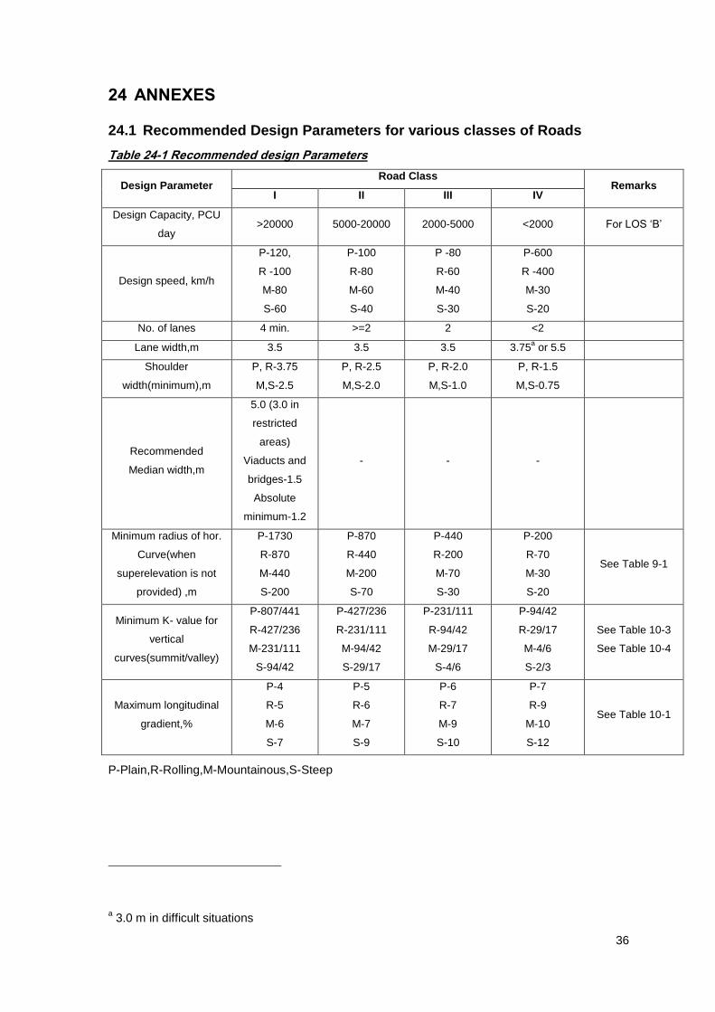
36
24 ANNEXES
24.1 Recommended Design Parameters for various classes of Roads
Table 24-1 Recommended design Parameters
Design Parameter Road Class
Remarks I II III IV
Design Capacity, PCU
day >20000 5000-20000 2000-5000 <2000 For LOS „B‟
Design speed, km/h
P-120,
R -100
M-80
S-60
P-100
R-80
M-60
S-40
P -80
R-60
M-40
S-30
P-600
R -400
M-30
S-20
No. of lanes 4 min. >=2 2 <2
Lane width,m 3.5 3.5 3.5 3.75a or 5.5
Shoulder
width(minimum),m
P, R-3.75
M,S-2.5
P, R-2.5
M,S-2.0
P, R-2.0
M,S-1.0
P, R-1.5
M,S-0.75
Recommended
Median width,m
5.0 (3.0 in
restricted
areas)
Viaducts and
bridges-1.5
Absolute
minimum-1.2
- - -
Minimum radius of hor.
Curve(when
superelevation is not
provided) ,m
P-1730
R-870
M-440
S-200
P-870
R-440
M-200
S-70
P-440
R-200
M-70
S-30
P-200
R-70
M-30
S-20
See Table 9-1
Minimum K- value for
vertical
curves(summit/valley)
P-807/441
R-427/236
M-231/111
S-94/42
P-427/236
R-231/111
M-94/42
S-29/17
P-231/111
R-94/42
M-29/17
S-4/6
P-94/42
R-29/17
M-4/6
S-2/3
See Table 10-3
See Table 10-4
Maximum longitudinal
gradient,%
P-4
R-5
M-6
S-7
P-5
R-6
M-7
S-9
P-6
R-7
M-9
S-10
P-7
R-9
M-10
S-12
See Table 10-1
P-Plain,R-Rolling,M-Mountainous,S-Steep
a 3.0 m in difficult situations

37
24.2 Sight Distance Formulas
24.2.1 Stopping Distance
Stopping distance is calculated as a sum of the
a)distance travelled by the vehicle during perception and brake reaction time(first term in
equation 24.1) and
b)the braking distance(second term in equation 24.1)
2546.3
2VVtS ... ... ... ... ... ... ... 24-1
Where,
V-design speed
t-perception and brake reaction time, taken as 2.5 s
- co-efficient of longitudinal friction, depends on the speed (taken as per Table 24-2)
Table 24-2 : Coefficient of longitudinal friction
Speed(km/h)
20 0.40
30 0.39
40 0.39
60 0.38
80 0.36
100 0.35
120 0.34
24.2.2 Overtaking Distance
a. Overtaking distance is calculated considering the optimum condition in which the overtaking
driver can follow the vehicle ahead for a short time while he assesses his chances for
overtaking, pulls out his vehicle, overtakes the other vehicle at design speed of the highway,
and returns to his own lane before meeting any oncoming vehicle from the opposite direction
travelling at the same speed.
b. Time components for various maneuvers and corresponding overtaking distances are given
below in Table 24-3

38
Table 24-3 :Overtaking Distance Calculations
Speed, km/h
Time Components,s
Overtaking Distance,m
For Overtaking Maneuvers
For Opposing Vehicle
Total
40 9 6 15 165
60 10.8 7.2 18 300
80 12.5 8.5 21 470
100 14 9 23 640
120 16 10 26 880
24.3 Horizontal Curve
a. Radius of horizontal curve is selected based on the following criteria:
The centrifugal force developed on the vehicle negotiating a horizontal curve should not
be more than the balancing force of friction and superelevation.
The vehicle should be stable against overturning.
The road should be visible to a sufficient distance that is illuminated in a horizontal plane
by the headlight of the vehicle during night driving time.
The visibility of the road ahead should not be obstructed by objects on the inner side of
the horizontal curve.
The wear and tear of vehicle tires should be minimum.
Passengers and drivers of the vehicle should not feel excessive lateral force from the
view point of comfort of travel.
b. Among all above criteria the first one usually governs in the road design.
c. Radius of horizontal curves is decided in such a way that the centrifugal force acting on the
vehicle is balanced by superelevation and side friction.
d. Basic equation for finding the radius of horizontal curve from the condition of equilibrium of
centrifugal force, superelevation and friction is given below:
)(127
2
fe
VR
... ... ... ... ... ... ... 24-2
Where,
R-Radius of Horizontal Curves, m
V-Design speed in km/h
e- Superelevation provided
f- co-efficient of lateral friction, depends on the speed (taken as per Table 24-4)

39
Table 24-4 : Coefficient of lateral friction
Speed(km/h) f
120 0.09
100 0.12
80 0.14
60 0.17
40 0.23
30 0.28
20 0.33
e. Radius of curve calculated from the above consideration usually gives a very sharp curve. As
a consequence passengers travelling on such curves experience discomfort with high lateral
force acting on their body.
f. So where site conditions permit it is recommended that radius of horizontal curve be decided
based on the lateral force acting on the passenger caused by the centrifugal force thereby
limiting the ratio of lateral to vertical forces to 0.15.
g. From the consideration of passengers comfort
20
2VR ... ... ... ... ... ... ... 24-3
Where,
R-Radius of Horizontal Curve, m
V-Design speed in km/h
24.4 Elements of a Clothoid
a. Length of transition curves is decided based on the allowable rate of change of centrifugal
acceleration acting on the vehicle so that the driver can steer the vehicle easily from straight
section to a circular curve section of the road.
CR
VL
47
3
... ... ... ... ... ... ... 24-4
Where,
L = minimum length of spiral, m;
V = speed, km/h;
R = curve radius, m;
C = rate of increase of lateral acceleration, m/s3(
VC
75
80, subject to the condition
8.05.0 C )
b. It is not possible to place a transition curve between straight and circular sections if following
condition is not fulfilled
RL ... ... ... ... ... ... ... 24-5
Where,
L-length of the spiral,m

40
-Deflection angle, in radians
R-Radius of circular curve,m
Since is always less than , from the above it follows that
RL ... ... ... ... ... ... ... 24-6 i.e L cannot be more than R .
c. No transition curve is required if the lateral shift (S in Figure 24-1) of the circular curve due to
transition curve is less than 0.25m.i.e.
25.024
2
R
L... ... ... ... ... ... ... 24-7
Where,
L-length of the spiral,m
R-Radius of circular curve,m
Figure 24-1: Elements of a transition or spiral curve
Notations to Figure 24-1:
BC-Beginning of the curve
EC-End of the curve
BCC-Beginning of the circular curve
ECC-End of the circular curve
R-Radius of the circular curve
xs,ys- abscissa and ordinate of any point on the spiral(origin of coordinates at tangent point or BC
with direction of abscissa towards IP)
Δ
φ

41
l- length of the spiral from BC to the current point(xs,ys)
xc,yc-abscissa and ordinate of any point on the circular curve(origin of coordinates at the BCC with
direction of abscissa along the tangent at that point)
L-length of the spiral
T- tangent length
IP-Intersection point
Lc-length of the circular curve
s-shift of the spiral
-Deflection angle
-angle of the spiral
Coordinates of points along the spiral are found as follows:
8
9
4
5
345640 A
l
A
llxs ... ... ... ... ... ... ... 24-8
10
11
6
7
2
3
422403366 A
l
A
l
A
lys ... ... ... ... ... ... ... 24-9
Where,
RLA -Parametre of the spiral
Length of the circular curve equals( in radians)
R
LRLc ... ... ... ... ... ... ... 24-10
Coordinates of circular curve are calculated as follows
R
lRx c
c sin ... ... ... ... ... ... ... 24-11
R
lRy c
c cos1 ... ... ... ... ... ... ... 24-12
Shift s equals
R
Ls
24
2
... ... ... ... ... ... ... 24-13
Angle of the spiral (in radians) equals
R
L
2 ... ... ... ... ... ... ... 24-14
Length of the tangent T equals

42
2
3
128022tan
R
LLRT
... ... ... ... ... ... ... 24-15
24.5 Summit Curve
a. The length (L) and K-value of vertical summit curve should be selected based on
the required visibility of at least stopping distance as given on Table 8-1. For this purpose
the driver‟s eye is assumed to be located at 1.2 m above the road surface and any object
lying on the roads surface to be 0.15m high.
the required visibility of at least overtaking distance as given on Table 8-2 or twice the
stopping distance. For this purpose the driver‟s eye is assumed to be located at 1.2 m
above the road surface.
Figure 24-2: Summit Curve
b. Minimum length of summit curve from the consideration of stopping distance is to be found as
follows:
When stopping distance(S) is less than L
221
2
200 hh
ASL
i.e.
440
2ASL ... ... ... ... ... ... ... 24-16
When stopping distance(S) is more than L
A
hhSL
2
212002
i.e.
ASL
4402 ... ... ... ... ... ... ... 24-17
Where,
L-Length of summit curve ,m
A-Algebraic difference in approach grades,%
When S<L h1=1.2m h2=0.15m for stopping sight distance h2=1.2m for overtaking sight distance
When S>L h1=1.2m h2=0.15m for stopping sight distance h2=1.2m for overtaking sight distance
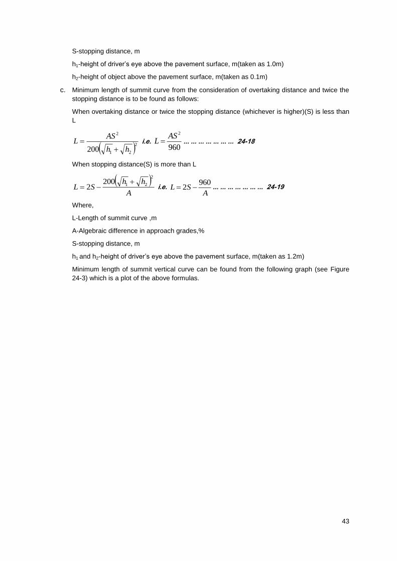
43
S-stopping distance, m
h1-height of driver‟s eye above the pavement surface, m(taken as 1.0m)
h2-height of object above the pavement surface, m(taken as 0.1m)
c. Minimum length of summit curve from the consideration of overtaking distance and twice the
stopping distance is to be found as follows:
When overtaking distance or twice the stopping distance (whichever is higher)(S) is less than
L
221
2
200 hh
ASL
i.e.
960
2ASL ... ... ... ... ... ... ... 24-18
When stopping distance(S) is more than L
A
hhSL
2
212002
i.e.
ASL
9602 ... ... ... ... ... ... ... 24-19
Where,
L-Length of summit curve ,m
A-Algebraic difference in approach grades,%
S-stopping distance, m
h1 and h2-height of driver‟s eye above the pavement surface, m(taken as 1.2m)
Minimum length of summit vertical curve can be found from the following graph (see Figure
24-3) which is a plot of the above formulas.

44
Figure 24-3: Minimum Length of Summit Vertical curve
24.6 Valley Curve
a. The length (L) and K-value of vertical valley curve should be selected based on the required
night visibility by the headlight of the vehicle of at least stopping distance as given on Table
8-1 or based on the riding comfort of the passengers and overloading on the suspension
system of the automobile.
b. On valley curves during night driving the top of the headlight beam should illuminate the road
to a distance more than the stopping distance
c. For calculation of the distance illuminated by the headlights, the height of headlight above the
road surface (H) is assumed to be 0.75m and the total angle of the headlight beam (2 ) is
assumed to be 2 deg.
0
200
400
600
800
1000
1200
1400
1600
1800
2000
0 2 4 6 8 10 12 14 16
Len
gth
of
sum
mit
Cu
rve
(L),
m
Algebraic Difference of Grades,A(%)
Minimum Length of Summit Curve
L>S
L<S

45
Figure 24-4: Valley Curve from headlight illumination criteria
d. When stopping distance(S) is less than L
sin200
2
SH
ASL
i.e.
S
ASL
5.3150
2
... ... ... ... ... ... ... 24-20
When stopping distance(S) is more than L
A
SHSL
sin2002
i.e.
A
SSL
5.31502
... ... ... ... ... ... ... 24-21
Where,
L-Length of valley curve ,m
A-Algebraic difference in approach grades,%
S-stopping distance, m
H-height of headlight above the pavement surface, m (taken as 0.75m)
-half of the angle of the headlight beam, deg (taken as 1 deg)
e. Minimum length of valley curve (L) from the consideration of the riding comfort of the
passengers and overloading on the suspension system of the automobile is found as follows:
a
AVL
1296
2
i.e 390
2AVL .... ... ... ... ... ... ... 24-22
Where,
L-Length of valley curve ,m
A-Algebraic difference in approach grades,%
V-design speed in km/h
a-maximum allowable overloading coefficient(taken as 0.3 m/s2)

46
f. Higher of the values obtained from the above considerations is taken for the design.
g. Minimum length of valley vertical curve can be found from the following graph (see Figure
24-5) which is a plot of the above formulas.
Figure 24-5:Minimum Length of Valley Curve
0
100
200
300
400
500
2 4 6 8 10 12 14 16
Len
gth
of
valle
y C
urv
e(L
),m
Algebraic Difference of Grades,A(%)
Minimum Length of Valley Curve
L>S
L<S

47
24.7 References
a. AASHTO: A policy on Geometric Design of highways and streets,Washington
DC,AASHTO,2001
b. ESCAP:Asian Highway Handbook,United Nations,New York,2003
c. IRC 64:1990 : Guidelines for capacity of Roads in Rural Areas,New Delhi,IRC,1990
d. IRC 73:1980:Geometric Design Standards for Rural (Non-urban)-Highways,New
Delhi,IRC,1980
e. SNIP 2.05.08: Awtomobilnye Dorogi(Russian Roads Standards),Moscow,2008
f. NRS 2045:Nepal Roads Standards,Kathmandu,Department of Roads,2045 BS
g. TRRL:ORN-6 A Guide to Geometric Design:TRRL, Crowthorne Berkshire United
Kingdom,1988
h. Babkov V F:Design of Highways(in Russian),Transport,Moscow,1988
i. Traffic Safety Unit: Traffic Signs Manuals Vol-I and Vol II,Department of
Roads,Kathmandu,1997
j. Garber,Hoel:Principles of Traffic And Highway Engineering,Cengage Learning,New
Delhi,2010
k. Kadiyali,Lal:Principle and Practices of Highway Engineering,Khanna Publishers,New
Delhi,2004

48
INDEX
acceleration, 28, 39 access, 2, 27, 33 ADT, vi, 2, 23, 35 aesthetic, 18, 31 barriers, 16, 21, 33 bicycle track, 23 Bridge, 29, 35 bus lay bys, 24 camber, 7, 17, 26 capacity, 3, 4, 15, 24, 47 carriageway, 2, 8, 15, 16, 17, 20, 21, 26, 30,
35 classification, 1, 3 Climbing Lane, 35 Climbing lanes, 10, 11 Cross Section, 15 Culvert, 35 Curbs, 25 deceleration, 24, 28 design speed, 5, 8, 10, 15, 27, 28, 37, 45 Design Speed, 5, 7, 10, 14, 15, 17, 28, 35 Design Vehicles, 3 District Roads, 1 drainage, 10, 26, 29, 30, 35 Emergency escape ramps, 11 extrawidening, 8 Feeder Roads, 1 footpaths, 20, 23 Formation width, 17 Functional Classification, 2 gradients, 10, 11 hair pin bends, 7, 8 Intersections, 28, 29
K-value, 13, 14, 32, 42, 44 landscape design, 31 length of valley curve, 15, 45 Levels of Services, 4 lighting, 26, 30 Local Roads Network, 2 Lux, 35 medians, 16, 17, 21, 25, 26, 32 National Highways, 1 pavement, 13, 14, 15, 16, 17, 25, 26, 27, 30,
33, 35, 43, 45 pedestrian, 23, 24 plantation, 32 quadratic parabola, 12 radius, 6, 7, 9, 10, 13, 32, 36, 38, 39 retaining walls, 29, 30 Right of way, 20 Road Humps, 22 set-back distance, 9 shoulder, 16, 20, 26, 35 sight distance, 5, 6, 9, 13, 14, 30 slopes, 18, 21, 22, 26, 27, 29 Strategic Roads Network, 2 summit curve, 12, 13, 14, 15, 42, 43 superelevation, 7, 8, 17, 36, 38 terrain, 2, 3, 4, 5, 16, 17 Terrain, 5 Transition Curves, 7 tunnels, 26, 30, 31 Urban Roads, 1 valley curve, 12, 14, 15, 44, 45 vertical clearance, 21, 24 vertical curves, 12, 14, 15, 32, 36


