NAVI-DRILL MOTOR HANDBOOK
101
NAVI-DRILL MOTOR HANDBOOK Ninth Edition December, 2002
Transcript of NAVI-DRILL MOTOR HANDBOOK

NAVI-DRILL MOTOR HANDBOOK
Ninth Edition December, 2002

© Baker Hughes Incorporated, 2002 ALL RIGHTS RESERVED The information contained herein is believed to be accurate and based on sound engineering principles. However, Baker Hughes INTEQ makes no warranties or representations to that effect. All such information is furnished �as is�, and use of such information is entirely at the risk of the user. Unauthorized copying of the information contained herein, including photographs and drawings, is prohibited and subject to penalties under copyright and other laws of the United States and other countries.


Preface Since its introduction in 1975, the Navi-Drill® motor has established itself as the industry standard for performance and reliability. Navi-Drill motors have accumulated millions of drilling and circulating hours in thousands of directional and horizontal wells worldwide.
Baker Hughes INTEQ introduced the Navi-Drill Ultra Series in 1995. These new-generation tools still produce the most power and drill at the highest rates of penetration in the industry.
The Navi-Drill Ultra Series was the first Baker Hughes INTEQ product to be designed and manufactured using the Product Development and Management Process (PDM), where inputs from customers, training and maintenance personnel, systems engineers, and manufacturing experts were sought and incorporated into the design specification. This produced a family of fit-for-purpose equipment and covered the full spectrum of our customers� drilling activities.
This ninth edition of the Navi-Drill Motor Handbook includes performance data on the new motor generation�the Navi-Drill® X-treme® Series. A new manufacturing process ensures that these performance motors provide 50 to 100% higher torque compared to the Ultra Series motors.
Baker Hughes INTEQ Navi-Drill Motor Series
Navi-Drill1975
Ultra Series1995
X-treme Series2002
As an essential step toward ensuring quality products, we implemented accredited quality management systems throughout the facilities involved in producing our motors. All Baker Hughes INTEQ manufacturing facilities have achieved ISO 9001 or Q1 certification.
This handbook also includes information about special applications and configurations of the Navi-Drill motors and information on tools and services provided by Baker Hughes INTEQ that incorporate Navi-Drill technology or enhance Navi-Drill performance.


i
Table of Contents PREFACE TABLE OF CONTENTS LIST OF FIGURES Chapter 1 - INTRODUCTION TO NAVI-DRILL® MOTORS Technical Basics ������������������........ 1 - 1 Ultra Series Motors������������������... 1 - 3 X-treme Series Motors ����������������... 1 - 4 Power Sections ��������������������.. 1 - 4 Mach 1XL ����������������������.. 1 - 5 Mach 1X ���������������������........ 1 - 5 Mach 1XL-P ���������������������.. 1 - 5 Mach 1X-P ��������������������......... 1 - 6 Mach 1Xi-P (Intermediate Radius) ����������......... 1 - 6 Mach 1ADM (Air Drill Motor) �������������... 1 - 6 Mach 1C ���������������������........ 1 - 7 Mach 1P �����������������������. 1 - 7 Mach 2PXL ���������������������... 1 - 7 Mach 4XL ����������������������. 1 - 8 Mach 4XL-P ���������������������.. 1 - 8

ii
Temperature Capabilities ���������������� 1 - 8 Rotor Catching Device �����������������. 1 - 9 Flow Rate Capabilities �����������������. 1 - 9 Chapter 2 - APPLICATIONS AND CONFIGURATIONS
Steerable and Horizontal Drilling ������������...
2 - 1
Standard Configuration ���������������........ 2 - 3
Stabilization ��.......��������������. 2 - 4 Drill-String Rotation ��������������.. 2 - 4
Medium and Intermediate Radius Configurations �����....... 2 - 4
Thruster �����������������������.
2 - 5
Performance Drilling ������������������ 2 - 6 Air and Foam Drilling �����������������.. 2 - 7 Vertical Drilling �������������������� 2 - 8 Casing while Drilling ������������������ 2 -10 Hole Opening �������������������........ 2 -11 Re-entry Drilling �������������������... 2 -11 Chapter 3 - OPERATIONS PLANNING Drilling Fluid Overview ����������������... 3 - 1 Drilling Fluid Types ������������������. 3 - 1 Water Based Fluids �����������������....... 3 - 2 Invert Emulsion Fluids �����������������. 3 - 2 Drill-In Fluids �������������������....... 3 - 2
Highly Compressible Drilling Fluids�������...... 3 - 3

iii
Lost Circulating Material (LCM) �������������. 3 - 4 Sand Content (Abrasive Particles) �����������........ 3 - 4 Solids ����������������������........ 3 - 4 Temperature / Fluid Effects ���������������.. 3 - 5
Stator Elastomers ���������������... 3 - 5 Temperature Operating Range ����������... 3 - 6
Dogleg Severity Capabilities ��������������� 3 - 6 DLS Capability ��������������������. 3 - 6 Deflection Device and Setting �������������...... 3 - 6 Dogleg Severity (Build up Rate) Charts ���������....... 3 - 7 Stabilization ���������������������... 3 - 7 Rotor Nozzle Configuration ���������������. 3 - 8 Special Operational Services ��������������... 3 - 9 Reaming and Back-reaming ���������������. 3 - 9 Overpull and Jarring ������������������. 3 - 9 Drilling Cement Float Equipment �����������........ 3 -10 Equipment Options ������������������.. 3 -10 String Bypass Valve ������������������. 3 -10 Float Valve ���������������������... 3 -11 Chapter 4 - SOFTWARE Drilling Application Software ��������������. 4 - 1 GeoBUR ���������������������....... 4 - 1 AKO Charts ���������������������.. 4 - 1 Thruster ���������������������......... 4 - 2 Under-Balanced Drilling Utility ������������....... 4 - 2 Torque & Drag ��������������������. 4 - 2 Drilling System Hydraulics ���������������.. 4 - 3 Compressible Fluid Flow (EC*TRAK) ���������........ 4 - 4 BHA Analysis (EC*TRAK) ���������������. 4 - 4 BHASYS ���������������������...... 4 - 5 BHASYSPro ���������������������. 4 - 5

iv
Appendix A - PERFORMANCE DATA SPECIFICATIONS
Ultra Series 2-7/8" M1ADM Ultra Series Motor ������������. A- 1 2-7/8" M2PXL Ultra Series Motor ������������... A- 2 3-1/8" M1X Ultra Series Motor �������������� A- 3 3-1/8" M1XL Ultra Series Motor �������������. A- 4 3-1/8" M1ADM Ultra Series Motor ������������. A- 5 3-3/4" M1XL Ultra Series Motor �������������. A- 6 4-3/4" M1X Ultra Series Motor �������������� A- 7 4-3/4" M1XL Ultra Series Motor �������������. A- 8 4-3/4" M1XL/RF Ultra Series Motor �����������... A- 9 4-3/4" M1ADM Ultra Series Motor ������������. A-10 4-3/4" M1X-P Ultra Series Motor ������������� A-11 4-3/4" M1Xi-P Ultra Series Motor ������������... A-12 4-3/4" M2PXL Ultra Series Motor ������������... A-13 6-1/2" M1X Ultra Series Motor �������������� A-14 6-1/2" M1XL Ultra Series Motor �������������. A-15 6-1/2" M1ADM Ultra Series Motor ������������. A-16 6-1/2" M1X-P Ultra Series Motor ������������� A-17 6-1/2" M2PXL Ultra Series Motor ������������... A-18 6-3/4" M1X Ultra Series Motor �������������� A-19 6-3/4" M1XL Ultra Series Motor �������������. A-20 6-3/4" M1ADM Ultra Series Motor ������������. A-21 6-3/4" M1X-P Ultra Series Motor ������������� A-22 6-3/4" M2PXL Ultra Series Motor ������������... A-23 8" M1XL Ultra Series Motor ��������������� A-24 8" M1ADM Ultra Series Motor �������������� A-25 9-1/2" M1XL Ultra Series Motor �������������. A-26 9-1/2" M1ADM Ultra Series Motor ������������. A-27 11-1/4" M1P Ultra Series Motor �������������.. A-28 12-3/4" M1P Ultra Series Motor �������������.. A-29 X-treme Series 2-3/8" M1X-P X-tremeTM Motor �������������.. A-30 2-7/8" M1X-P X-tremeTM Motor �������������.. A-31 3-1/2" M1XL-P X-tremeTM Motor ������������... A-32 3-1/2" M1Xi-P/LS X-tremeTM Motor �����������... A-33 3-1/2" M1X-P/LS X-tremeTM Motor ������������ A-34 3-1/2" M2XL-P X-tremeTM Motor ������������... A-35 4-3/4" M1XL-P X-tremeTM Motor ������������... A-36 4-3/4" M4XL X-tremeTM Motor �������������... A-37 6-3/4" M1XL-P X-tremeTM Motor ������������... A-38

v
X-treme Series - continued 6-3/4" M4XL-P X-tremeTM Motor ������������... A-39 9-1/2" M1X-P X-tremeTM Motor �������������.. A-40 12-3/4" M1X-P X-tremeTM Motor ������������� A-41
Appendix B - NOZZLE SIZE CHARTS Appendix C � ABBREVIATIONS
List of Figures Figure 1 - Effect of Lobe Configuration on Torque and Speed �... 1 - 2 Figure 2 - Navi-Drill Motor Components ������................ 1 - 4 Figure 3 - Rotor Catching Device ������������� 1 - 9 Figure 4 - Rotary vs. Oriented Drilling ����������� 2 - 1 Figure 5 - Example for 3-Point Geometry ���������� 2 - 2 Figure 6 � Steerable Motor with Adjustable Kick Off Sub ���.. 2 - 3 Figure 7 - Thruster Work Principle �����������...... 2 - 5 Figure 8 - Typical Thruster BHA ������������..... 2 - 6 Figure 9 - VertiTrak System ��������������..... 2 - 8 Figure 10- Drilling Liner ����������������... 2 -10 Figure 11- Incompressible Drilling Fluids ���������... 3 - 3 Figure 12- Bearing Housing and Clamp-On Stabilizer ����.... 3 - 7 Figure 13- Bypass Valve Function ������������... 3 -10


1 - 1
Chapter 1
Introduction to Navi-Drill® Motors
Technical Basics The Baker Hughes INTEQ Navi-Drill tool is a positive displacement motor (PDM) used as a downhole drive in deep drilling operations. The motor employs a reverse application of the pump principle first established by René Moineau in which circulating drilling fluid is used to drive the drill bit independently of drillstring rotation. The Moineau principle holds that a helical rotor with one or more lobes will rotate when placed eccentrically inside a stator having one more lobe than the rotor. The rotor and the stator form a series of sealed cavities so that when drilling fluid is pumped into the tool the rotor will be driven in an eccentric, rotary motion relative to the stator, allowing the fluid to pass while transmitting rotational power to the drive train and bit. Torque and rotational outputs can be varied by employing different rotor/stator lobe configurations. In general, more torque will be generated by configurations employing greater numbers of lobes.
The output torque is proportional to the differential pressure across the power section. Increased weight on bit (WOB) is seen on surface as increased standpipe pressure. Maximum torque is limited by the mechanical strength of the stator elastomer. This material must be rigid enough to withstand abrasion and wear caused by solids in the drilling fluid but, at the same time, be sufficiently flexible to provide a pressure seal between the rotor and the stator. As the length of the power section and the number of lobes increase, the total chamber volume and the torque output increase. A longer power section improves volumetric efficiency at a slight cost in mechanical efficiency. Practical limits to power section length, and thus overall tool length, are imposed by logistical and rig-site handling difficulties, and by the need to incorporate the tool into a usable bottomhole assembly (BHA).
Torque and rotational outputs can be varied by employing different rotor/stator lobe configurations. In general, a higher number of lobes produce increased torque and a lower number of lobes generate increased speed. Additionally, rotational speed is proportional to the circulation or flow rate for a given lobe configuration. The eccentric placement of the rotor in the stator causes the axis of the rotor to rotate about the axis of the stator. This movement acts as a gear reduction mechanism and causes bit speed to reduce as rotor/stator lobe configuration increases. To center the eccentric rotor rotation, a titanium flex shaft is employed below the rotor. The inner parts of the motor bearing assembly include high performance axial and radial bearings.

1 - 2
Torq
ue [f
t lb
x 10
00]
10
8
6
4
2
01/2 3/4 5/6 7/8
Motor ConfigurationBasis for comparison:Size � 6-3/4�, Flow rate � 475 GPM, ConstSame number of stages, Same presSame lobe geometry, Same efficiency.
Spee
d [rp
m]
9/10 11/120
100
200
300
400
500
600
700
ant motor length,sure drop across entire motor,
Figure 1 � Effect of Lobe Configuration on Torque and Speed
Navi-Drill motors cover the full range of drilling operation requirements with regard to tool size, bit speed, torque, and flow rate. The Navi-Drill motor operates effectively with most types of drilling fluids in a wide range of fluid weights and viscosities, including air, mist, and foam. Several types of elastomer are available for the Navi-Drill fleet, depending on the temperature, the type of Navi-Drill motor, and the drilling environment.
Special motor configurations can also reliably reproduce outstanding performance in higher temperature environments. For example, Navi-Drill motors have an excellent track record in the Austin Chalk in temperatures up to 420°F (215°C).
The common mud systems usually impose no general limitations but a mud/elastomer test can be conducted in a questionable situation prior to making the final elastomer selection. Baker Hughes INTEQ has a comprehensive database with test results on most common and uncommon mud systems. Based on the knowledge from the database, special precautions and motor configurations can be used to enhance tool life expectancies. For closer review, please contact your Baker Hughes INTEQ representative.

1 - 3
Ultra Series Motors The Navi-Drill Ultra Series high performance, positive displacement motors incorporate significant design enhancements to provide a new standard of drilling performance. Compared to previous generations the Navi-Drill Ultra Series delivers:
• Increased reliability
• Longer drilling runs
• Greater horsepower and torque
• Improved penetration rates
• Improved temperature capabilities
Rugged Drive Train - The Navi-Drill Ultra Series drive train is built for long, hard service. Each motor incorporates an industry-proven, rugged bearing assembly, drive sub, and flex-shaft. The drive train has been thoroughly proven over millions of hours of downhole service. This demonstrates that the higher torque developed by the extended length XL power sections can be reliably delivered to the bit over long drilling intervals and under the most demanding conditions.
Stronger Connections and Higher Grade Materials - Upgraded connections throughout the motor have twice the makeup torque ratings of previous generation tools, preventing downhole backoff during tough and dynamic drilling applications. These strengthened connections - along with higher-grade materials in the drive train and power section - allow bending moments 150% higher than previous designs, increasing motor reliability and drilling performance in both straight and directional holes.
Improved Power Section - Navi-Drill Ultra Series motors are designed and manufactured in-house with optimized rotor-stator (power) sections that improve available fluid hydraulics, providing significant increases in horsepower and torque at the bit. Navi-Drill Ultra Series motors equipped with optimized extended-length (XL) power sections outperform, and are more reliable than, previous dual-power section designs.
X-treme Power Technology - Some Ultra Motors incorporate portions of the X-treme power technology, which is the latest development in downhole motor technology. This technology uses pre-contoured steel stator tubes, which reduce the amount of elastomer in the power section by up to 60%. The X-treme power section handles increased differential pressures creating as much as 50 to 100% higher torque above Ultra Series standards. On Ultra motors, X-treme technology is used to shorten the power section for increased dogleg capabilities, while maintaining the same power output.

1 - 4
Bearing Housing Titanium Flex Shaf
t Rotor Catching Device
Rotor Stator
Figure 2 � Navi-Drill Motor Components
X-treme Series Motors Baker Hughes INTEQ X-treme Series performance motors are the strongest since the invention of downhole motors. They were designed to maximize effective rate of penetration (ROP) and increase dogleg
capabilities. Compared to the Ultra Series motors, the X-treme Series motors have higher operating torque capabilities and power output.
X-treme motors include high torque M1XL-P power sections that are capable of handling even most aggressive polycrystalline diamond compact (PDC) bits for improved ROP while eliminating the risk of motor stalls. This is achieved by using pre-contoured steel stator tubes coated with a thin layer of elastomer.
X-treme motors with high speed M4XL X-treme power simpregnated bits.
ections are used with
e equipped with
Most X-treme Series motors use a different stabilization concept than Ultra motors. Using a shorter steering head, the stabilization on the X-treme motor is optimized to ensure straight tangent drilling in the rotary mode and high dogleg capabilities in the sliding mode.
Increased ROP very often requires an increased weight on bit. To compensate for the additional loading, X-treme motors arbearing assemblies, housing special ball or diamond bearings that provide increased WOB capabilities.
Power Sections Ultra Series and X-treme motors are available in a large variety of configurations, covering the entire operational envelope in tool sizes from 2-3/8� up to 12-3/4� and in various designs for high torque and high-speed applications to demonstrate reliability in combination with all types of bits.

1 - 5
Mach 1XL The Mach 1XL power section is one of the strongest in the Ultra Series motor fleet. It provides, in each available tool size, high torque at moderate rotational speed and provides high performance in all parts of the well path.
M1XL motors are typically used in straight-holes, tangents, extended reach, and horizontal wells in combination with rock or PDC bits.
5/6
Mach 1X The Mach 1X power section is the short version of the M1XL power section. It has fewer stages and, therefore, provides less power and torque. The flow rate and bit speed range are identical to the M1XL power sections. Due to fewer stages, the M1X power section is shorter and is used to drill higher dogleg severities (DLS).
The main application is to build angle and to drill ahead after passing curves that are too tight for the M1XL power sections to pass through.
5/6
Mach 1XL-P The M1XL-P power section (precontoured stator tube) is designed for X-treme motors to cover high torque performance applications. It maximizes effective ROP in any high WOB or high Torque On Bit (TOB) application by making use of aggressive PDC bits. The use of this bit type is recommended to deliver the extreme power to the formation.
The M1XL-P power section is generally applicable in the same operations as the M1XL � straight hole and tangent sections, extended reach drilling, or horizontal extension applications that may require extreme aggressive PDC bits.
5/6

1 - 6
Mach 1X-P The M1X-P power section is shorter than the M1XL-P. Although it has less power and less torque than the XL-P version, it can be driven with the same flow rate, and will provide the same rotational speed.
This power section is used with Ultra motors for high ROP in performance markets that use higher doglegs and delivers power comparable to the Ultra Series M1XL. It may be used with low to moderate aggressive PDC bits or roller cone bits.
5/6
Mach 1Xi-P (Intermediate Radius) M1Xi-P motors are Baker Hughes INTEQ�s intermediate radius motors for very high dogleg severities. M1Xi-P power sections are available with X-treme technology (precontoured stators tubes) and deliver built rates up to 60°/100ft (30m).
The tools provide high torque, improved reliability and a rugged design even under these drilling conditions.
5/6
Mach 1ADM (Air Drill Motor) Conventional downhole motors designed for use with incompressible drilling fluids are not optimized for use in air or foam drilling. For these applications, Baker Hughes INTEQ has designed the Mach 1ADM which has a large chamber volume that results in low bit speed even at elevated flow rates. Relatively low pressure is required to generate sufficient torque for drilling, reducing the need for a booster compressor. Because of the low bit speeds, these tools also have applications when using conventional drilling fluids, especially when using roller cone bits. The low speed is accompanied by high torque output, allowing high WOB to be applied.
7/8

1 - 7
Mach 1C The Navi-Drill Mach 1C power section has a 5/6 lobe configuration. It is available in 11-1/4" size only. It is characterized by its short length, moderate speed, and high torque generation.
It is designed for directional and horizontal drilling applications with roller cone or PDC bits.
5/6
Mach 1P The Mach 1P is a high torque motor with a 9/10 lobe configuration. These motors are offered in larger sizes for low flow environments that require high torque motors.
9/10
Mach 2PXL In contrast to the Mach 1 power sections, the M2PXL has a 2/3 rotor/stator lobe configuration. This results in increased rotational speed with reduced torque, providing the operational conditions suitable for the use of high-performance fixed-cutter bits such as PDC, TSP, or natural diamond bits.
The XL length makes the Mach 2PXL applicable for straight hole, extended reach, or horizontal extension wells.
2/3
1 - 8
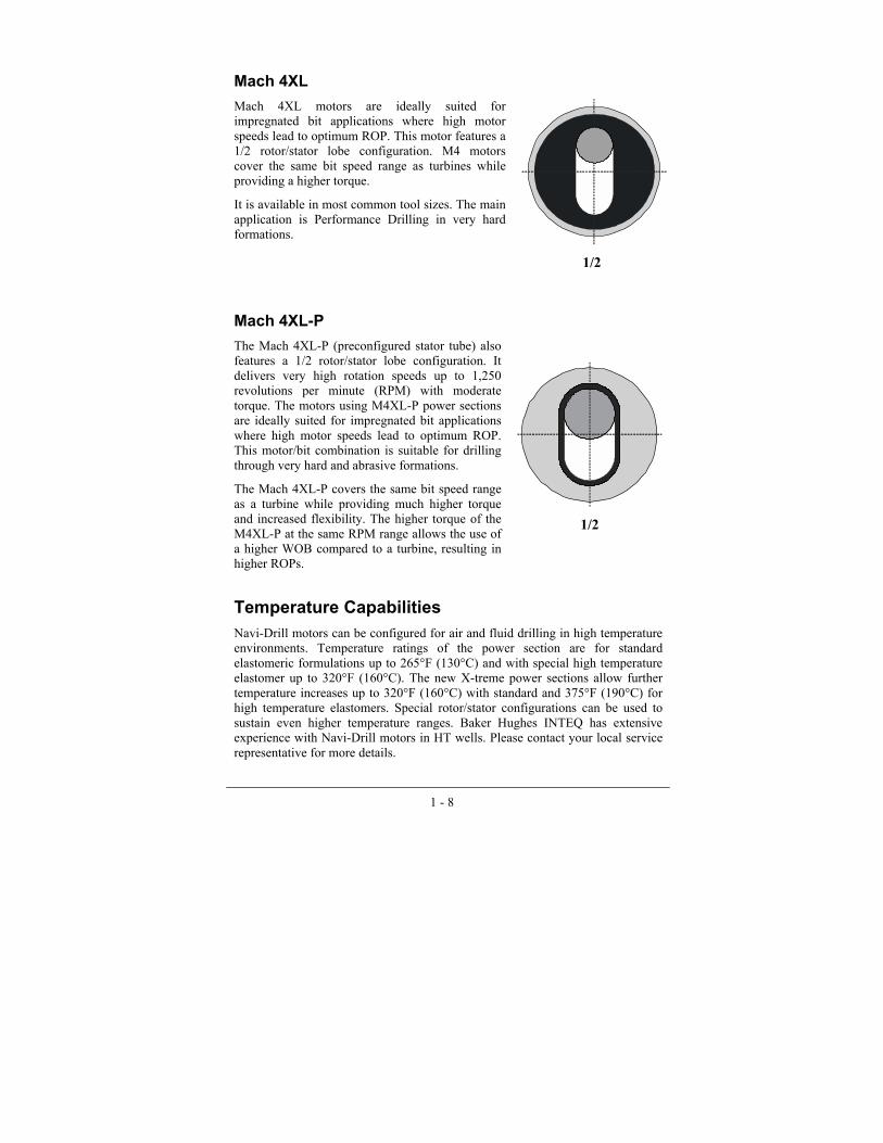
Mach 4XL Mach 4XL motors are ideally suited for impregnated bit applications where high motor speeds lead to optimum ROP. This motor features a 1/2 rotor/stator lobe configuration. M4 motors cover the same bit speed range as turbines while providing a higher torque.
It is available in most common tool sizes. The main application is Performance Drilling in very hard formations.
1/2
Mach 4XL-P The Mach 4XL-P (preconfigured stator tube) also features a 1/2 rotor/stator lobe configuration. It delivers very high rotation speeds up to 1,250 revolutions per minute (RPM) with moderate torque. The motors using M4XL-P power sections are ideally suited for impregnated bit applications where high motor speeds lead to optimum ROP. This motor/bit combination is suitable for drilling through very hard and abrasive formations.
The Mach 4XL-P covers the same bit speed range as a turbine while providing much higher torque and increased flexibility. The higher torque of the M4XL-P at the same RPM range allows the use of a higher WOB compared to a turbine, resulting in higher ROPs.
1/2
Temperature Capabilities Navi-Drill motors can be configured for air and fluid drilling in high temperature environments. Temperature ratings of the power section are for standard elastomeric formulations up to 265°F (130°C) and with special high temperature elastomer up to 320°F (160°C). The new X-treme power sections allow further temperature increases up to 320°F (160°C) with standard and 375°F (190°C) for high temperature elastomers. Special rotor/stator configurations can be used to sustain even higher temperature ranges. Baker Hughes INTEQ has extensive experience with Navi-Drill motors in HT wells. Please contact your local service representative for more details.
1 - 9
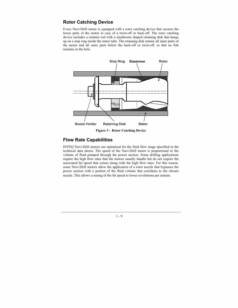
Rotor Catching Device Every Navi-Drill motor is equipped with a rotor catching device that secures the lower parts of the motor in case of a twist-off or back-off. The rotor catching device includes a retainer rod with a mushroom shaped retaining disk that hangs up on a stop ring inside the stator tube. The retaining disk retains all inner parts of the motor and all outer parts below the back-off or twist-off, so that no fish remains in the hole.
Elastomer
Figure 3 � Rotor Catching Device
Flow Rate Capabilities INTEQ Navi-Drill motors are optimized for the fluid flow range specified in the technical data sheets. The speed of the Navi-Drill motor is proportional to the volume of fluid pumped through the power section. Some drilling applications require the high flow rates that the motors usually handle but do not require the associated bit speed that comes along with the high flow rates. For this reason, some Navi-Drill motors allow the application of a rotor nozzle that bypasses the power section with a portion of the fluid volume that correlates to the chosen nozzle. This allows a tuning of the bit speed to lower revolutions per minute.


2 - 1
Chapter 2
Applications and Configurations
Steerable and Horizontal Drilling A steerable motor system can alternate between two modes � oriented or rotary � without having to trip out of the hole. In the oriented mode, without string rotation, the system induces a predetermined wellbore curvature. In the rotary mode with suppressed string rotation, the assembly can be configured either to maintain a constant trajectory or to build or drop according to the needs of the well plan. In general, these systems are capable of rotation through certain doglegs depending on tool configuration and hole size.
Figure 4 - Rotary vs. Oriented Drilling
The outside diameters and placement of the stabilizers help determine the rotary drilling characteristics. The assemblies can be designed to achieve build, hold, or slight drop tendencies in rotary mode.

2 - 2
The dogleg capability in the oriented mode can be estimated by using a simple 3-point geometry approach, neglecting bending and formation effects, or a more complex analytical approach, resulting in results that are more accurate but requiring special software and trained software users.
Figure 5 � Example for 3-Point Geometry
Figure 5 shows the basic concept of the three-point geometry approach for a stabilized, bent housing, steerable system. In this example, the three points of stabilization are the bit gauge, the Navi-Drill bearing housing stabilizer, and the string stabilizer (or top stabilizer). The distances from the midpoint of the string stabilizer to the midpoint of the bearing housing stabilizer (L1) and from the bearing housing stabilizer to the bit gauge (L2), together with the effective angle α define a reduced arc that represents the theoretical DLS capability of the system.
The bit tilt angle α is the resulting angle between bit axis and a line through the centers of the top and bottom stabilizers. The calculation is dependent on assumptions regarding stabilizer gauge, hole gauge, and stiffness of the Navi-Drill components. Advanced analytical software is available to calculate the theoretical DLS for a specific BHA even more precisely by using a Finite Element approach and considering the entire BHA and the wellpath.
Due to the high effort for each calculation, this procedure is only used for specific applications. The 3-point geometry approach is generally the standard procedure used to predict the dogleg severity of a tilted motor.

2 - 3
It is normal practice to configure a steerable system so that its DLS capability in oriented mode slightly exceeds the maximum required in the well plan. This allows for higher than planned doglegs to be drilled if it becomes necessary.
An obvious advantage of a steerable system is that the same steerable assembly can be used in rotary mode for a tangent or horizontal section without the need for a trip to change or adjust the BHA. Minor course adjustments can be made with occasional oriented sections.
Steerable assemblies also are required where a hole section passes through a variety of formation types that exhibit different rotary build or drop tendencies. Short corrective sections drilled in oriented mode will keep the well path on course.
Where long tangent sections or horizontal extensions are planned, the Adjustable Kick Off Sub (AKO) setting should be kept as low as possible to minimize side loading on the bit and the Navi-Drill bearing section, ensuring maximum service life and optimizing hole quality.
Standard Configuration
The configuration of the tool is driven by the needs of the specific drilling application and motor systems and should be planned to help optimize the drilling process.
The AKO is the standard deflection device for all Navi-Drill motors. It is positioned between the power section and the bearing assembly. The tilt angle of the AKO can be adjusted on the rig floor. The AKO can be set to 0° for applications that do not require steerability. For example, a 0° setting is used when drilling out cement and casing float equipment.
Bit
Bearing Assembly
Adjustable Kick Off Sub
PowerSection
Figure 6 � Steerable Motor with Adjustable Kick Off Sub
Maximum AKO settings vary, especially with tool type, tool size and hole size. Charts detailing the expected DLS capability for given AKO settings and rotating limits are shown on the internet at www.bakerhughesdirect.com (after logging in, select INTEQ > Engineer Toolbox).

2 - 4
Stabilization
The 3-point geometry determines directional behavior and wellbore curvature when a Navi-Drill steerable system is used in the oriented mode. The stabilizer blade width, profile, and hard facing material all contribute to successful steering with minimal difficulty in transferring weight to the bit.
Additional stabilizers in the BHA will not necessarily improve steering performance and may increase torque in the rotary mode and drag in the oriented mode. Nevertheless, additional drilling assembly stabilization may be required to improve buckling and dynamic stability and to assist in the centralization of certain MWD formation evaluation modules.
Drill-String Rotation
The maximum allowable rotation speed is limited by the strength of the motor components. The actual limit depends on the specific motor configuration. It is defined for all common motor configurations and AKO angles on the internet at www.bakerhughesdirect.com (after logging in, select INTEQ > Engineer Toolbox). For certain configurations, no rotation is allowed beyond specified AKO angles. Rotation speeds should be selected after consideration of drill-string harmonic vibration modes in order to avoid conditions where resonance may occur. Chapter 4 introduces BHASYSPro, a dynamic modeling tool.
Medium and Intermediate Radius Configurations
Ultra Series motors of the M1X group can be used to drill medium radius curves to approximately 15°/100ft (30m). The exact limit varies with tool size and configuration. Intermediate Radius Motors M1Xi-P are capable of drilling curves up to a DLS of 60°/100ft (30m).
Compressive Service Non-Magnetic Drill Pipe (CSNMDP) can be used in place of conventional non-magnetic drill collars in high build rate applications. Special flexible MWD systems are available for use in combination with CSNMDP.
For detailed recommendations of Navi-Drill configurations for medium and intermediate radius horizontal drilling applications, please contact your Baker Hughes INTEQ Representative or Drilling Coordinator.

2 - 5
•
•
•
•
Thruster Baker Hughes INTEQ�s Thruster drilling system efficiently maintains a constant WOB, reduces downhole vibrations, and compensates for non-uniform axial drillstring movements. These capabilities provide operators with:
improved ROP and extended bit life
enhanced steerability
fewer tool and string failures
increased maximum possible well displacement
The Thruster is a hydraulic cylinder with a piston. The drillstring and the Thruster housing represent the cylinder, while the piston includes all the tools located below the Thruster (i.e., bit, mud motor). The hydraulic force caused by the pressure inside the cylinder acts on the piston, creating the thrust force.
Figure 7 � Thruster Work Principle
The thrust force depends on the cross sectional area of the piston and the differential pressure between the piston and the annulus. Any tool or device below the Thruster that creates a pressure drop contributes to the WOB.
The Thruster acts as an �anti-vibration� tool as long as it is kept in a floating position. The thruster�s pump-open behavior decouples the lower part of the BHA from the reminder of the drillstring, providing a constant WOB and a stable tool face orientation. Simultaneously, the system dampens axial shocks and vibration and compensates for uncontrolled axial string movements (i.e., during sliding operations on long, horizontal sections).
Drillers derive maximum benefit from the Thruster by placing it as close to the bit as possible. A Measurement While Drilling (MWD) tool may be placed between the motor and the Thruster to provide near-bit directional and formation evaluation (FE) measurements.

2 - 6
Figure 8 � Typical Thruster BHA
Performance Drilling Performance drilling is defined as using an optimized integral BHA to increase the overall ROP and save downhole drilling time in comparison to existing offset wells. The overall ROP results from the systematic approach to tackle existing problems with the right use of applicable Navi-Drill motors. The high performing X-treme Series motors are applicable in vertical wells, build sections, and tangent sections of directional wells or in horizontal well extensions.
The use of a high torque Navi-Drill motor enhances the drilling process in two ways: first, by delivering a high level of continuous torque to the bit at a speed that can be tailored to the formation and the type of bit being used; and second, by isolating the bit from the most detrimental effects of torsional drill-string vibration. These effects include erratic torque and speed, backward rotation, and periods of no rotation, conditions generally referred to as �stick-slip.�

2 - 7
The full range of available bits�polycrystalline diamond compact (PDC), thermally stable PDC (TSP), natural diamond, and Tricone�has its applications in performance drilling. The use of an Ultra Series or X-treme Series motor allows the bit to work in conditions for which it was designed.
Often the use of a highly aggressive PDC bit is preferred, since it allows higher ROP and drilling hours compared to roller cone bits. However, the use of aggressive bits may lead to difficulties in maintaining a stable toolface orientation during oriented drilling operations. In those cases, the Baker Hughes INTEQ Thruster tool helps solve the problem.
The complete system might include a Navi-Drill motor providing rotational power and torsional shock absorption, an anti-whirl bit and a hydraulic thruster to absorb axial movement and to generate a constant WOB.
It is important to consider the Navi-Drill/bit/thruster combination as a system when designing the hydraulics program for the application. Advantage� software is available to optimize the setup of such a performance BHA. Baker Hughes INTEQ has conducted numerous successful performance drilling programs for different customers in various parts of the world, significantly improving ROP and eliminating drill-string component failures.
The economic value of the Navi-Drill performance drilling option will include various less tangible benefits such as reduced casing wear, reduced drill pipe wear, and the cost savings associated with fewer trips.
For a detailed recommendation, please contact your Baker Hughes INTEQ representative or Drilling Coordinator. A designated performance drilling group is available to review and assist in optimizing your drilling program.
Air and Foam Drilling Downhole motors were initially designed to be used with a conventional drilling fluid. The fluid acts as a power source, provides lubrication, and dissipates the heat from the motor. These motors have limitations when used with air, mist, or foam as the circulating medium.
Much higher volumes have to be circulated to obtain adequate hole cleaning, because of the lower drill cuttings lifting capacity of air, mist, and foam. These high flow rates must be considered when selecting the downhole motor.
The M1ADM Ultra Series motor was specifically designed for air and foam applications. It features significantly larger chamber volumes to allow higher flow rates and to provide a lower rotational speed to reduce the risk of overspeeding (i.e. when lifting off bottom).
Because of the compressibility of air, motor stalls are not signaled by an abrupt increase in standpipe pressure as would be the case with conventional drilling fluids, but are generally indicated by an immediate loss of ROP. Standpipe pressure must be reduced before lifting off bottom to restart a stalled motor or when a connection is to be made. Allowing the motor to run freely off bottom

2 - 8
may cause it to exceed its design speed limit and could lead to severe internal damage. Some lubrication of the downhole motor, typically liquid soap, is required to reduce friction and associated stator wear.
Air, foam, or mist drilling projects require special planning; please contact your Baker Hughes INTEQ Representative or Drilling Coordinator.
Vertical Drilling
Baker Hughes INTEQ�s VertiTrak® system is the industry�s first automated vertical drilling system. It delivers reliable deviation control in multiple applications ranging from salt drilling to faulted zones and highly fractured formations without compromising preferred drilling parameters.
Figure 9 - VertiTrak System

2 - 9
VertiTrak incorporates an X-treme high-performance power section and pad steering technology from our proven AutoTrak system. Like AutoTrak, VertiTrak is a downhole closed-loop system with two-way communication.
VertiTrak is the ideal system for drilling highly dipped formations and fault zones, such as those encountered in mountainous areas. Other applications include salt formations, which are extremely susceptible to deviation tendencies when drilling with PDC bits, and lean casing profiles requiring precise wellbore placement. The VertiTrak system is available to drill hole sizes ranging from 8-1/2" to 26".
The advanced VertiTrak system keeps the well absolutely vertical, reduces wellbore stability problems, and increases the gross ROP. The VertiTrak system is a downhole closed-loop steering system that continuously measures inclination and generates the steering forces required to correct any deviation from vertical. An integrated mud pulser transmits inclination and tool status information to the surface.
Drilling a perfectly vertical well reduces torque and drag and improves wellbore quality, facilitating more efficient lean casing profiles, and helping extend the well�s horizontal reach. Compared to standard steerable motor assemblies, VertiTrak systems reduce hole spiraling also.
Typically, the VertiTrak system operates in the sliding mode with the pads engaged and bit rotation provided by a Navi-Drill X-treme power section. Integrated, near-bit sensors measure hole inclination and pulse this data continuously to the surface. Whenever the VertiTrak system�s near-bit inclinometers detect the well path beginning to deviate from vertical, the control sub activates internal hydraulic pumps. These pumps are engineered to deliver the necessary force (up to 3 tons per pad) to each of the three steering pads - counteracting any deviation tendencies and pushing the wellbore back to 0° inclination.
The VertiTrak closed-loop system provides continuous, incremental course corrections to ensure the wellpath remains straight with as little tortuosity as possible. This reduces torque and drag, and minimizes the likelihood of twist-off and stick/slip problems. As a result, the VertiTrak system helps control both BHA and casing wear later.
Although VertiTrak typically drills in sliding mode, the pads generally can be disengaged to permit rotary drilling and optimize penetration rates. The VertiTrak system�s near-bit sensors continuously monitor and pulse inclination to the surface while the tool is rotating. With disengaged pads, the even correction of the wellpath is disabled as the pads are retracted into the housing to prevent them from damage.
For more detailed information about the VertiTrak system, please contact your Baker Hughes INTEQ Representative or Drilling Coordinator.

2 - 10
Casing while Drilling Baker Hughes INTEQ�s innovative Drilling Liner system can drill and case a well simultaneously. The system runs the liner while drilling and prevents hole collapse caused by sudden pore pressure changes and/or formation instability.
A typical (reentry or new well) application for the Drilling Liner system is a wellbore featuring a formation with high pore pressure followed by another layer with significantly lower pressure (depleted reservoir). Normal drilling operations usually run into trouble while drilling through the high pressure formation and then drilling into the low pressure layer, as severe mud losses with simultaneous hole collapse are the common result.
Further applications include drilling unconsolidated sands and drilling time dependent unstable formations
With the Drilling Liner system, the liner will be set simultaneously when drilling into the low pressure formation. Although the mud losses and the hole collapse still occur, the liner is then already in place and protects the borehole. After cementing and changing the mud, the regular drilling operation may resume in the low pressure formation.
The Drilling Liner system is composed of an outer and an inner assembly.
Figure 10 � Drilling Liner

2 - 11
The inner assembly components include a pilot bit, male sub, motor and Thruster. Field-proven Navi-Drill Ultra Series or X-treme motors deliver superior cutting torque to the pilot bit. Retractable drive splines also transmit torque to the outer assembly to ensure that the core bit and the pilot bit turn together.
The downhole Thruster above the motor compensates for the assembly�s varying thermal expansions and leaves the liner in tension at all times.
The outer assembly components include a core bit, female sub, suspension, and bearing sub. In addition to cutting action, the core head provides guidance for the inner assembly�s pilot bit. The suspension and bearing sub provides longitudinal length suspension and radial guidance � ensuring only the core bit and female sub turn.
For detailed information about the Drilling Liner system, please contact your Baker Hughes INTEQ Representative or Drilling Coordinator.
Hole Opening The Ultra Series and the X-treme Series motors are ideal for hole opening operations, as the additional cutting face requires higher torque to turn the bit/reamer. Normally, a Ream While Drilling (RWD) bit is used that drills a pilot hole and simultaneously opens the hole to the chosen size in one run. With special design features, these bits are highly Steerable Ream While Drilling (SRWD) and can achieve the same dogleg capabilities as standard bits.
Alternatively, the Ultra and X-treme Series systems can be used in conjunction with string RWD tools, allowing the passage or drillout without rotation of the underreamer in the casing or liner, which could cause damage to the completion equipment or damage the casing shoe integrity.
Re-entry Drilling Ultra Series and X-treme Series systems for re-entry work form part of the complete Baker Hughes INTEQ Re-entry Technology package designed to extend and increase production from mature fields. Available E-line Systems like OrientXPress and CoilTrak systems can be used as well as rotary drilling BHAs for TTRD re-entry applications. A wide variety of Ultra Series and X-treme Series sizes and configurations have applications in re-entry wells, but smaller tool sizes predominate. X-treme technology was implemented down to 2-3/8" and 2-7/8" tool sizes to eliminate the risk of motor stalling and to generate sufficient torque/power at low flow rates. Thru tubing drilling is best when handled as a system. Such a system requires an integrated BHA to drill a successful well.


3 - 1
Chapter 3
Operations Planning
Drilling Fluid Overview All types of drilling fluids can be used with the Navi-Drill motor, although with some reservations with regard to oil-base mud. Water-base systems with high chlorides may pose some problems with regard to stress corrosion cracking in all elements of the drill-string, including the Navi-Drill motor. The same applies for acid gas influxes into the circulating system.
Cleaning the motor and flushing it with non-petroleum based lubricant can reduce corrosion of motor components when the Navi-Drill motor is racked back or in transit from the rig. Polymer drilling fluids help with lubricity and are attractive fluids to use with the Navi-Drill motor as they allow good cuttings carrying capacity with minimal solids content.
Oil-base fluids have the advantage of providing good lubricity, both internally in reducing rotor/stator friction and motor bearing wear and externally in reducing torque and drag. Their greater thermal stability also reduces fluctuations in rheology at elevated temperatures.
Your Baker Hughes INTEQ Representative or Service Coordinator might recommend mud / stator rubber compatibility tests. Baker Hughes INTEQ has conducted extensive testing of the elastomeric reaction on worldwide existing drilling fluids. This information is organized in a database for use in planning processes. It might also be beneficial to utilize Baker Hughes INTEQ�s test facility for pre-well fluid analysis if the reaction is unknown or highly reactive.
Drilling Fluid Types There are three basic drilling fluids used throughout the world today:
•
•
•
Water based fluids (WBM)
Invert emulsion fluids�synthetic- or oil-based fluids (SBM/OBM)
Drill-in fluids
Fluids selection criteria include environmental constraints, borehole stability issues, production zone integrity, and overall drilling costs.
3 - 2
Water Based Fluids
Water based fluids can be combinations of fresh water fluids to saturated salt fluids, dispersed bentonite systems, or non-dispersed bentonite/polymer systems. Various chemical additives are used to enable WBMs to drill reactive formations efficiently. Some of the WBM systems Baker Hughes INTEQ Drilling Fluids have available are AQUA-DRILL� glycol system, Alplex® aluminum chemistry, NEW-DRILL® partially-hydrolyzed polyacrylamide, and PYRO-DRILL® a multiple co-polymer high temperature system. A typical deepwater water based fluid would be a salt, PHPA NEW-DRILL® system. The PHPA is an encapsulator to ensure the cuttings remain intact during removal. The salt adds density, aids hydrate inhibition and gives the fluid shale inhibition characteristics. Hydrate suppression additives such as NF2� or NF3� are added for additional protection when required.
When selecting either a WBM or an OBM, not only is wellbore stability an issue, but ROP and the lubricious characteristics of the two systems also play a role in the fluid selection. However, there are additives for WBMs that are designed to increase ROP and reduce torque and drag. Adding PENETREX®, Baker Hughes INTEQ�s Drilling Fluids� ROP enhancer, to a WBM system at 2 to 5% by volume may substantially increase ROP and reduce torque and drag.
Invert Emulsion Fluids
Synthetic-based fluids and oil-based fluids are classified as invert emulsion fluids if they contain a water/brine phase and �all oil� if there is no water phase. The internal phase usually consists of calcium chloride brine with chlorides ranging from 115,000 ppm to 160,000 ppm. Typical SBM/OBM fluids have oil to water ratios ranging from 95:5 to 70:30.
The advantages of SBM/OBM include formation stability, increased ROP, gauge hole, gas hydrate suppression, lubricity, reduced corrosion and, often, lower overall well costs. Disadvantages include lost circulation (often more costly and more severe compared to WBM), environmental concerns and elastomer compatibility.
Various types of base fluids are used to formulate SBM. The SYN-TEQ® fluid is Baker Hughes INTEQ�s Drilling Fluids� original SBM. Formulations are made with various hydrocarbon derivative base fluids including isomerized olefins, linear alpha olefins, paraffins, and combinations of all of the above. Ester-based SBMs are non-hydrocarbon derivatives and are more environmentally friendly. NEXESSM and BIO-GREEN� are the two ester-based systems supplied by Baker Hughes INTEQ Drilling Fluids.
Drill-In Fluids
Drill-in fluids are used when protection of the production zone is desired. These fluids are used mainly in cases where open hole completions such as gravel packs, stand-alone screens, slotted liners and bare-foot completions are planned.
3 - 3
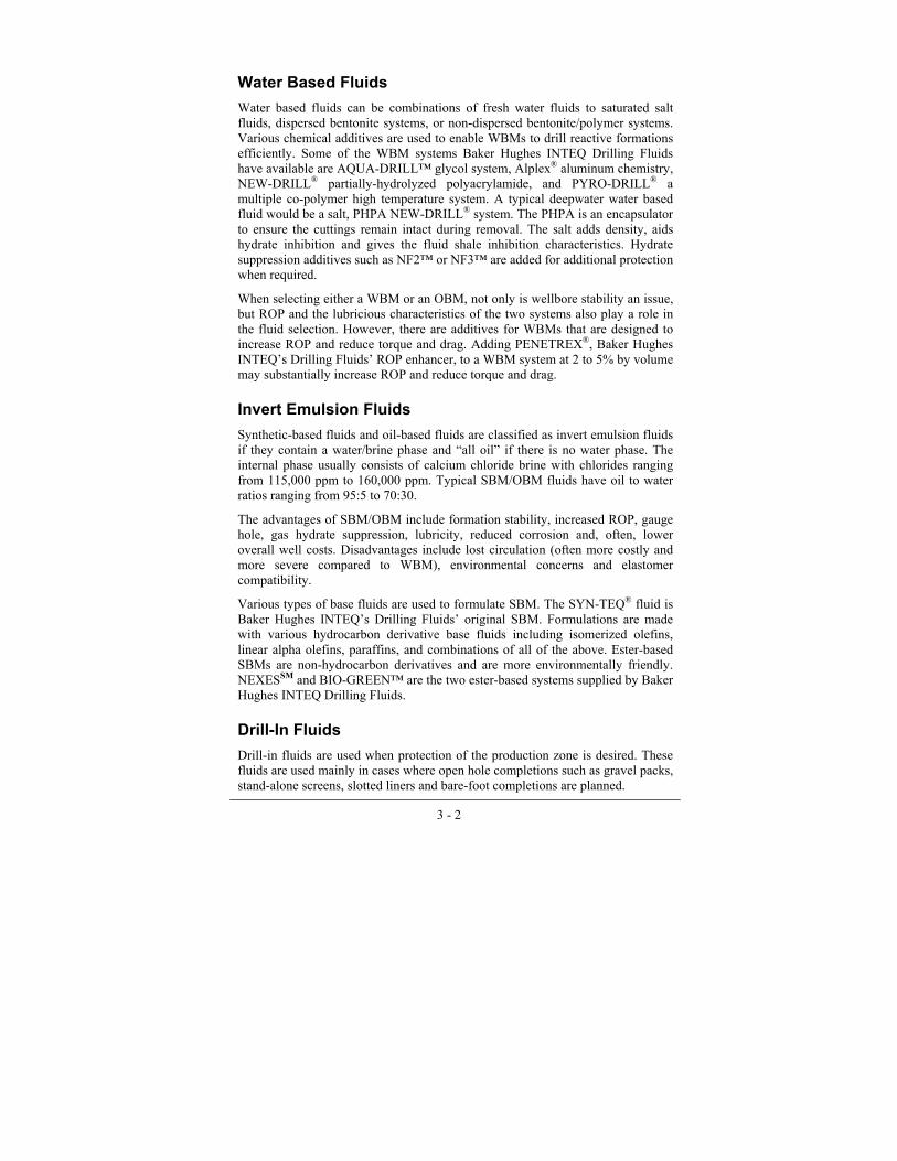
The PERFFLOW® fluid system is one of Baker Hughes INTEQ�s Drilling Fluids� drill-in fluids. The system uses polymers for viscosity and fluid loss control and incorporates sized calcium carbonate for bridging off the pore throats of the production formation. The fluid loss additives and bridging agent are designed to minimize fluid invasion and form an easily removable filter cake. PERFFLOW® systems can be made up with fresh water or a brine depending on fluid density requirements.
Figure 11 � Incompressible Drilling Fluids
Highly Compressible Drilling Fluids
Highly compressible fluids are generally associated with underbalanced drilling. They have densities ranging from 6.95 ppg, with back pressure, down to 0 ppg. They are comprised of gasses, mists, foams, and aerated liquids with high gas to liquid ratios. Conventional drilling motors are not designed for use in compressible fluids and have problems including shortened life, stalling, and runaway. INTEQ�s ADM incorporates a special design that employs much larger chamber volumes to give lower output rotational speeds for a given flow rate and lower pressure drops than conventional motors. This provides the advantages of improved motor efficiency, fewer stalls versus conventional motors, and reduced chances of overspeed. They can be used with the entire range of compressible fluids and liquid drilling fluids as well.

3 - 4
• •
Lost Circulating Material (LCM) Navi-Drill motors can be used with common lost circulation material (LCM). Some of the most common types of LCM in use today are sized and flaked calcium carbonates, walnut hulls, cellophane, cellulosic material and mica. There are three important parameters to consider: grain size, quantity per barrel, and mixing preparation. LCM can lead to plugging of the inner fluid ways of the Navi-Drill motor (e.g., bonnet ports). Circulation of the mud system and well control can become impossible.
Recommendations for maximum LCM size are:
LCM less than or equal to 1/4" for motor sizes 4-3/4" and larger LCM less than 3/16" for motor sizes 3-7/8" and 3-1/8"
There is also the influence of LCM abrasiveness on the motor, especially the stator, to be taken into account. There is no definitive limit. In general, a mix of 18 lb/bbl is considered the maximum, whereas 13 lb/bbl is considered normal. As long as the LCM fluid can be pumped with a centrifugal pump, no problems are expected for the Navi-Drill motor.
Careful mixing of LCM is essential to avoid clogging the by-pass valve, bearing assembly and possibly plugging the bit nozzles or fluid ways. Never �dump� LCM into the mud pits at the pump intake, always use a premix tank for mixing LCM.
Sand Content (Abrasive Particles) Too high sand contents in the mud system will lead to high abrasive wear on the stator and other Navi-Drill motor components. Therefore, for optimum motor life expectancy, sand content should be no more than a trace as determined by the American Petroleum Institute (API) sand content test.
Always use centrifuges or equivalent at the rig site to reduce the sand content. The abrasive property of sand is dependent on the grain form, grain size and grain sharpness. Field experience has indicated that acceptable motor life can be attained in most cases with API sand contents up to 1%. With more than 1%, a reduction of Navi-Drill motor life has to be expected. Other particles (e.g., scale or corrosion particles from the inner surface of the string or coil) can be very abrasive and must be avoided. Tool failures (totally worn stators after very few operating hours) can be caused by these particles.
Solids
The solids content in the mud is dependent on the required mud system, density, and operating conditions. Solids usually should not contain abrasive particles. Systems with high solids content do not necessarily lead to increased wear of motor and other components, as long as the particles are not too abrasive.

3 - 5
The low gravity solids (LGS), such as bentonite, polymers, and drill solids, should be less than 7% by volume, otherwise they can cause the fluid paths in the bearing assembly to �block off� and starve the bearing assembly of passing any fluid, resulting in bearing assembly failure. Solids control equipment should be kept in good working order.
Temperature / Fluid Effects
The selection of the appropriate power section depends on a variety of factors, e.g., downhole temperature, type of mud or chemical compounds. It is possible to use undersized rotors or oversized stators to achieve a customized rotor/stator fit. By selecting a loose fit, the power section is allowed to swell while maintaining its performance.
In addition, there are several elastomer types and different rotor coatings available that are used for different applications.
Your Baker Hughes INTEQ Representative or Service Coordinator will recommend the suitable solution for any application.
Stator Elastomers
The effects of different drilling fluids and fluid additives on Navi-Drill stator elastomers is the subject of continuous investigation at Baker Hughes INTEQ�s Drilling Systems Engineering Departments in Celle, Germany and in Houston, Texas. Detailed records of drilling fluid effects on various types of elastomer compounds are filed in a database.
The main concerns are synthetic-base drilling fluids (e.g., ester oils) and mineral oil-base (e.g., diesel oil) muds. The elastomers typically used for Navi-Drill stator linings are based on high-grade synthetic nitriles that exhibit good resistance to synthetic oil-base and water-base drilling fluids
The interaction between elastomer and drilling fluid can lead to swelling and loss of physical properties, e.g., hardness or elongation. Also, shrinkage (leading to an increased hardness) is observed sometimes. Swelling will increase the rotor stator interference and cause a higher strain and heat build-up in the elastometer. This increased specific loading of the elastomer finally leads to �chunking� - cracks and a fracture of the stator elastomer.
Diesel-based drilling fluids have been, to a large extent, displaced by low toxicity mineral oils or synthetic fluids. Although the synthetics usually contain no aromatics, they often have an adverse effect on stator elastomers. Pre-job testing of drilling fluid and elastomer compatibility is recommended where no previous experience (see BHI-database) has been logged. This service can be provided on request by our in-house laboratory.

3 - 6
Temperature Operating Range Standard Ultra stator elastomers are rated to 265°F (130°C); special high temperature elastomers rated to 320°F (160°C) are available for both oil- and water-base drilling fluids.
The Navi-Drill Mach 1ADM is specially suited for high temperature applications using conventional drilling fluids (rather than the air/foam for which it was originally designed). The large chamber volume and the rotor profile of this motor exert the least stress on the stator elastomer of any Navi-Drill motor. Therefore, its use is recommended in hot-hole environments where very low bit speed is acceptable.
Due to the reduced amount of elastomer, X-treme stators are also very suitable for HT applications. The standard types are rated to 320°F (160°C). Special high-temperature units are rated to 374°F (190°C) for both oil- and water-base drilling fluids.
Dogleg Severity Capabilities
DLS Capability
Steerable systems based on the Navi-Drill motor are dual-purpose: they are able to initiate and propagate wellbore deviation when used in the oriented mode (no drillstring rotation); and when rotated, they will drill ahead in much the same way as a conventional rotary assembly with increased performance due to the increased power at the bit.
Deflection Device and Setting
The choice of tool and its configuration will depend on what the BHA is expected to achieve. If the run is planned to kick-off the well from vertical or to initiate a sidetrack, an AKO setting towards the upper range of its adjustability is commonly used. The selected AKO setting should be able to generate a slightly greater dogleg severity than that specified in the well plan. This will allow the directional driller to meet the directional plan requirements if actual hole curvature is less than predicted.
It should be noted that the theoretical dogleg severity assumes that toolface orientation is constant, while in practice it will fluctuate to a certain degree, especially when using PDC bits on high torque tools. If the Navi-Drill motor is required to drill a vertical, tangent, or horizontal section with a constant trajectory, it will generally be configured with a low AKO setting. This allows for improved drilling performance and lower stress on the tool and bit while still allowing minor course corrections to be made without the need to trip the assembly.

3 - 7
Your Baker Hughes INTEQ Representative or Operations Coordinator can give advice on the expected performance of any particular tool size, hole size, and drilling parameter combination.
Dogleg Severity (Build up Rate) Charts Build up rate (BUR) charts predict the dogleg severity of fully stabilized, partially stabilized, or unstabilized (slick) Navi-Drill assemblies in the oriented mode depending on the AKO setting. In addition to the expected dogleg capability, the charts show the maximum allowable drillstring rotation in normal drilling conditions. A chart library of possible combinations of motor type and size, hole size, and stabilization is available on www.bakerhughesdirect.com (after logging in, select INTEQ > Engineer Toolbox).
Stabilization Stabilizers for steerable systems are usually slightly undergauged to allow efficient weight transfer to the bit and to minimize weight-stacking on the stabilizers. The bearing housing stabilizer has a similar function to the near-bit stabilizer of a conventional rotary assembly. Experience has shown that the string stabilizer, most commonly run immediately above the Navi-Drill motor, should be under-gauged so the assembly has an angle hold tendency in rotary mode.
Figure 12 - Bearing Housing and Clamp-On Stabilizer
The length, width, and profile of the blades for both the bearing housing and the string stabilizer can make a significant difference in the steerability of the assembly. Generally, the blades will be straight, relatively short, and profiled with smooth tapers at the top and bottom of the blades.
The hardfacing material is also important and should be as smooth as possible on the surface to reduce sliding friction when the Navi-Drill motor is used in the oriented mode. In addition, a near bit reamer can be used. Near bit reamers are stabilizers with cutting elements on the front edges of their blades. They are run between the bit and the mud motor. Near bit reamers are shorter than
3 - 8
•
•
•
conventional stabilizers to minimize the bending loads on the bearing section of the mud motor in curved hole sections during directional drilling operations.
Due to the additional guidance of the reamer blades, hole spiralling is reduced to a minimum and the borehole is kept in gauge. The cutting elements on the blades smooth the borehole walls by removing possible edges and offsets. The outer diameter of a near bit reamer typically is 1/32" to 1/16" under-gauge compared to the bit size, which ensures smooth sliding of the BHA even in curved borehole sections. The smoother wellpath enables easier sliding of the string and avoids hanging up of the BHA. Both effects result in steadier WOB with reduced peak loads on the BHA. Your Baker Hughes INTEQ Representative or Service Coordinator will recommend optimal stabilizer configurations.
Rotor Nozzle Configuration Some of the Navi-Drill motors allow the application of a rotor nozzle to increase the flow rate through the motor without increasing the bit speed at the same time or to reduce the pressure loads in case of a motor stall.
The maximum flow rate for a specific motor is given in the motor specifications and is driven by the following limitations:
Increase in flow beyond specified maximum differential pressure and flow may lead to washouts on the internal parts of the motor.
With higher flow, the rotor (motor) speed will also increase above motor specifications so that higher wear and tear is expected in all parts.
As the installation of a rotor nozzle will separate the total flow only in the power section, the use of a rotor nozzle will not increase the specified total flow rate range of the motor.
Another advantage of using rotor nozzles is that no additional float equipment is needed when the motor is tripped in/out the hole. Today�s high performance motors with the tight fit between the rotor and the stator will act as a valve and avoid drillstring fill up (or drain out) if the BHA is tripped in or when pulling out of hole (POOH). In these cases, �String Bypass Valves� may be used to allow fluid communication between the annulus and the string. If a rotor nozzle is used, sufficient flow is ensured and a String Bypass Valve might not be needed. Once the rotor is equipped with a nozzle, the hydraulic power of the motor is reduced by the bypassed fluid energy resulting in a reduced motor performance. If substantially more flow rate is needed the use of an additional circulation sub on top of the motor should be considered. Charts will help to determine the optimum nozzle size for each application. See Appendix B, APPENDIX B: Nozzle Size Charts. A vertical line is drawn
3 - 9
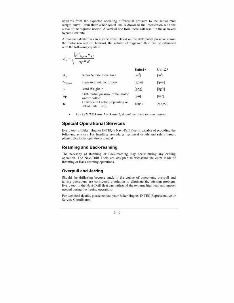
upwards from the expected operating differential pressure to the actual mud weight curve. From there a horizontal line is drawn to the intersection with the curve of the required nozzle. A vertical line from there will result in the achieved bypass flow rate.
A manual calculation can also be done. Based on the differential pressure across the motor (on and off bottom), the volume of bypassed fluid can be estimated with the following equation:
KpVA bypass
n **2
∆=
ρ
•
Units1* Units2* An Rotor Nozzle Flow Area [in2] [in2]
Vbypass Bypassed volume of flow [gpm] [lpm]
ρ Mud Weight in [ppg] [kg/l]
∆p Differential pressure of the motor on/off bottom [psi] [bar]
K Conversion Factor (depending on set of units 1 or 2) 10858 283750
Use EITHER Units 1 or Units 2; do not mix them for calculation.
Special Operational Services Every tool of Baker Hughes INTEQ�s Navi-Drill fleet is capable of providing the following services. For handling procedures, technical details and safety issues, please refer to the operations manual.
Reaming and Back-reaming
The necessity of Reaming or Back-reaming may occur during any drilling operation. The Navi-Drill Tools are designed to withstand the extra loads of Reaming or Back-reaming operations.
Overpull and Jarring
Should the drillstring become stuck in the course of operations, overpull and jarring operations are considered a solution to eliminate the sticking problem. Every tool in the Navi-Drill fleet can withstand the extreme high load and impact needed during the freeing operation.
For technical details, please contact your Baker Hughes INTEQ Representative or Service Coordinator.

3 - 10
Drilling Cement Float Equipment Float equipment can be drilled with Navi-Drill motors equipped with deflection devices, but extra caution should be exercised. Drillstring rotation should be limited to 20 to 40 RPM and the Navi-Drill unit run at a low differential pressure. Spudding with the Navi-Drill assembly to remove or break up the plug, float, or shoe is not recommended. Special care should be taken with PDC bits to prevent premature damage.
Equipment Options
String Bypass Valve
In the event a Navi-Drill assembly is run without a bypass nozzle in the rotor, a string bypass valve can be run above the motor. This allows the drillstring to fill when tripping in and for drilling fluid to drain from the string when tripping out. With no circulation, a spring holds the bypass piston in the open position, exposing the ports to the annulus and allowing drilling fluid to flow into or out of the drillstring. At approximately 30% of the maximum recommended flow rate, the bypass piston is forced down, closing the ports and circulating the fluid through the Navi-Drill power section and bearings. When circulation is stopped, the return spring restores the piston to the open position.
.
Figure 13 - Bypass Valve Function

3 - 11
Float Valve
A float valve run directly above the power section will avoid plugging of the bit and motor while tripping in the hole. It is especially recommended when milling steel, drilling under-balanced, or when drilling in very unconsolidated formations.


4 - 1
Chapter 4
Software
Drilling Application Software Drilling optimization when using motors often requires a detailed analysis of drilling program objectives and applications (e.g., mud vs. compressible fluids) and the capability of other drilling system components such as Thrusters or near bit reamer. Major elements of the planning process that relate to the choice and use of the appropriate motor configuration are described below.
GeoBUR
This program determines theoretical steady-state wellbore curvatures that would be established with AKO adjusted drilling motors as a function of general 3-point geometry motor conformation, high- or low-side toolface orientation, and radial-bearing clearance.
AKO Charts
Charts showing the predicted build rates or dogleg severities for various tool configurations and sizes are available from the AKO Charts application, which is embedded in INTEQ�s Advantage software platform. These charts are theoretical data generated from computer modeling of the motor components. Actual drilling conditions or variants of configurations may cause offsets from predicted performance. Advantage also offers an application called GeoBUR that provides Geometric Build-Up Rate calculations for configurations not published on www.bakerhughesdirect.com (after logging in, select INTEQ > Engineer Toolbox). The BHA Analysis or BHASYSPro software application is available to study other directional performance effects such as bit type, bending, or formation influences. The AKO Chart application also provides drilling performance data for motor systems in terms of torque, power, and bit speed for their flow rate ranges.

4 - 2
•
•
Thruster
The Thruster program is used to calculate the operating point (WOB range) of a BHA containing a Bit-Motor-Thruster system as a function of mud weight and flow rate. It can be used to optimize such a hydraulic system by comparing different BHA configurations and drilling conditions with one another. Warnings are given out for certain configurations or drilling conditions when operational problems can be expected. It is strongly recommended to run the Thruster program prior to any Thruster application.
Under-Balanced Drilling Utility
The Under-Balanced Drilling Utility is used to calculate the effective motor flow rate for two-phase flow based on fluid data, motor characteristics, and operating conditions. Two general calculation modes are available:
Effective Flow Rates Through Motor - Calculates the effective flow rate of the two-phase mixture through the motor. The calculation is done for No-Load pressure drop (bit off bottom), operating pressure drop, and maximum pressure drop of the motor while on bottom.
Maximum Allowed Gas Flow Rates - This calculation determines the maximum allowed gas flow rate that can be pumped without exceeding the motor flow rate limits. The gas flow rates are reported at standard conditions. The calculation is done for No-Load pressure drop (bit off bottom), operating pressure drop, and maximum pressure drop of the motor while on bottom.
Torque & Drag
A flexible and sophisticated analytical tool, Torque & Drag is used to conduct comprehensive engineering assessments of drillstring load, drillstring stress, and drillstring/wellbore contact-load problems commonly associated with directional drilling operations. Calculation modes are provided for four distinctly different problem-solving architectures:
• The Torque & Drag calculation mode provides complete surface-to-bit load, stress, and contact load information for rotary or non-rotary (oriented) drilling operations at a user-specified measured depth. A one-page summary report provides key surface-load information, such as hook load and rotary torque, for all operating load cases, as well as the magnitude, location, and mode of occurrence (e.g., drilling, slack-off, etc.) for maximum values of combined (von Mises), axial, torsional, and bending stress. The reports include warning messages for yield, buckling, and fatigue when appropriate. Detailed surface-to-bit reports

4 - 3
give comprehensive load, stress, normal load, and safety factor information on thirty-foot (ten-meter) stations.
• The Friction Factor calculation mode enables analytical inference of cased and open hole drillstring/wellbore friction factors from observed hook load and rotary torque data. Furthermore, this calculation mode enables the user to determine Bit Overpull and Bit Drag forces in case the corresponding observed surface loads and friction factors along the wellpath are specified.
• Bit Drag/Overpull Force calculation mode enables the user to determine bit overpull and bit drag forces (for example, Swab and Surge forces) in case the corresponding observed surface loads and friction factors along the wellpath are specified.
• The Depth In/Depth Out calculation mode provides a means for evaluating key drillstring operating loads as well as casing wall-thickness attrition over the course of drilling a user-specified interval. This calculation mode also can be used to evaluate the progressive onset of drillstring or coiled tubing lockup due to advanced helical buckling.
• Weight-on-Bit calculation mode reverses the drill-bit-to-surface solution process employed in the Torque & Drag, Friction Factor and Depth In/Depth Out calculation modes. It enables direct evaluation of drill bit or other downhole tool loading for coiled tubing or other drilling and non-drilling applications where gravity-aided load transfer may be inadequate and where supplemental thrust loads must be provided by means of a surface injector head or snubbing system to achieve required axial loads at total depth.
Drilling System Hydraulics
This is a multi-functional analytical tool for solving system hydraulics, hydraulics optimization, temperature and/or pressure influence (including HTHP) and cuttings transport problems related to circulation of incompressible Newtonian and non-Newtonian fluids in oilfield drilling applications. The user can select from four general solution architectures:
• The Spreadsheet Hydraulics calculation mode provides detailed pressure loss and hydraulic parameter data for complex circulating systems over a user-specified range of uniformly incremented circulation rates.
• System Mud Hydraulics runs the analysis for the operating flow rate. The emphasis is on the details of the wellbore system hydraulics with respect to pressure drop, flow regime, local ECD, and annular velocity.
• The Optimized Hydraulics (Calculated) calculation mode provides system circulation rate, detailed pressure loss, drill bit nozzle or flow

4 - 4
area, and optimization objective function solutions for maximum specific hydraulic horsepower or impact force at the drill bit. This optimization solution determines the minimum circulation rate for satisfactory cuttings transport.
• The Optimized Hydraulics (Rigsite) calculation mode provides a means whereby rig site observations of circulating system pressure losses at several circulation rates can be employed to forecast optimum drill bit nozzle or flow area selections for each drill bit run such that specific hydraulic horsepower or impact force will be maximized.
Compressible Fluid Flow (EC*TRAK) EC*TRAK is a program for analyzing drilling hydraulics problems associated with multi-phase compressible fluids, including wellbore inflow and drill cuttings transport. The program covers four main applications of drilling with multi-phase fluids. Particular consideration is in the downhole motor performance.
• The Two-Phase Fluid calculation mode provides detailed pressure loss and hydraulic parameter data for circulating the gas/liquid mixture through drillstring and annulus.
• The Mud with Gas Injection calculation mode combines conventional mud hydraulics with multi-phase flow in the annulus. This mode is effective in analyzing the influence of gas injection through a parasitic string or through the casing on the bottomhole pressure.
• The Foam calculation mode uses a specific viscosity correlation to characterize the rheology of a mixture of liquid and gas with an additive to analyze the flow through the drillstring and annulus.
• The Air Drilling mode is for the analysis of drilling with pure gas.
BHA Analysis (EC*TRAK) A structural analysis and predictive performance assessment tool, EC*TRAK facilitates studying the nature of large-scale drilling assembly deformation during drilling. EC*TRAK can predict the effect of drilling assembly deformation on static drilling assembly wall contact loads and, in combination with drill bit and formation influences, on directional drilling behavior. Two basic calculation modes are provided:
• The Compute Static Results calculation mode provides static structural analysis of a user-defined drilling assembly in wellbores of arbitrary 3-D spatial configuration. Computed results include orthogonal vertical-plane and lateral normal loads at all points of drilling assembly or drill bit contact with the wellbore, resultant force and direction vector for reactions at the drill bit, and MWD housing misalignment with respect to the wellbore centerline axis. The static structural analysis further provides information on lateral and angular deflection, radial clearance,

4 - 5
bending moment, axial bending, and combined stress distributions along the BHA.
• The Predict Well Path calculation mode provides a �drill ahead� prediction of drilling assembly directional performance in the form of a pseudo-survey file that progressively describes the drilling trajectory propagation over a user-specified course length, including dogleg severity in build and turn planes. Drill-ahead predictions can be made for conventional rotary drilling assemblies as well as drilling motor or turbine assemblies in both oriented and rotary operations.
BHASYS
BHASYS is a software program that models the tendency of a BHA and drillstring to deform axially, torsionally, or laterally.
When the RPM of a rotating drillstring matches any one of the natural bending, axial, or torsional frequencies of the drillstring, one or more sections of the drillstring will have a tendency to whirl laterally or vibrate axially or torsionally with continuously increasing amplitudes.
This deformation of the drillstring in the lateral, axial, or torsional direction (also called mode shapes) is different for each natural frequency.
This program provides information on natural frequencies and their associated mode shapes and bending stresses in various sections of the drillstring. It also computes the buckling load and buckled mode shape.
BHASYSPro
While BHASYS focuses on Critical Speeds Analysis to aid drilling operations select which operating parameters to run, during in-depth engineering studies more extensive dynamics analysis of BHA components is often needed. For these cases, BHASYSPro provides the skilled engineer with a versatile software tool for investigating the dynamic performance of BHA components.
BHASYSPro builds on the same user interface used in BHASYS, but focuses on full finite element analysis of a complex drillstring in a curved wellbore.
With BHASYSPro, the user can add BHA or drillstring components in exact detail, model complex BHA components, or study the dynamic or static response of the drillstring to a change in MWD tool design. BHASYSPro has also been validated with downhole measurements, and uses state-of-the-art 3D graphics to render complex engineering analyses.


A - i
Appendix A
APPENDIX A: Performance Data Specifications The following pages list the General Tool Specifications, Performance Data, and Operational Data for the most common Baker Hughes INTEQ Navi-Drill motors.
The General Tool Specifications include the most important geometrical dimensions. These include the length, weight, and connections. The stated outer diameter of the tool (Max. OD) is dependent on the type of motor. In all cases, the quoted number refers to an un-stabilized motor and the listed number refers to the part that represents the maximum OD, i.e. the wear pad of the adjustable kick-off housing.
The characteristics of a positive displacement motor (PDM) are a function of the design of the stator/rotor geometry. The available torque and rotational speed depend on the pitch angle and the number of lobes in the stator and rotor.
The original PDM design was the 1/2 lobe, which worked well with natural and synthetic diamond bits, but rotated too fast for roller cone bits. As a result, low speed, high performance PDMs were developed with multi-lobe configurations.
With a multi-lobe system, the relationship between speed and torque is changed with the number of lobes. The stator/rotor geometry dictates that a helicoidal steel rotor with one or more lobes is placed inside a stator having one more lobe than the rotor. The rotor/stator or lobe configuration is written with a slash between the two numbers: 1/2, 3/4, 5/6, 7/8, or 9/10.
The Performance Data depend on this lobe configuration. The technical information quotes operating parameters unless otherwise stated.
The flow rate range gives the operating envelope in which the motor will run efficient and optimized. This flow rate range results in the stated speed range that is directly related to the driving flow rate, the lobe configuration and the resulting chamber volume. Baker Hughes INTEQ chooses one operating point of the motor to quote the operating parameters. This means that the stated operating differential pressure relates to the operating torque at the operating flow rate with the resulting speed.

A - ii
Helpful Definitions:
Flow Rate Specified mud flow range through the power section of the motor
Maximum differential pressure
Differential pressure, which can be applied only for short intervals without accelerated wear/damage
Maximum torque
Torque at the bit at maximum differential pressure across the power section
No-load pressure
(off-bottom) differential pressure, which is required to overcome internal friction and pressure losses of the motor
Operating Differential Pressure
Nominal differential pressure across the power section during optimum operation
Operating Torque
Torque at the bit at operating differential pressure across power section
Power output Mechanical horsepower at nominal differential pressure and maximum flow rate
Speed Bit speed range, relating to flow rate. The minimum bit speed is achieved at minimum and max bit speed at maximum specified flow rate.
The mechanical horsepower output of a motor is defined as:
5252nTHPout
×=
HPout [hp] mech. horsepower output HPin [hp] hydr. horsepower input T [ft-lbs] Operating Torque dp [psi] Operating differential Pressure Q [gpm] Flow Rate n [RPM] Speed ηtotal [%] efficiency of entire PDM
And the input horsepower is defined by the differential pressure and the flow rate:
1714QdpHPin
×=
Example: 6-3/4� M1XL-P X-treme Motor (see page A-38)
HPrpmlbsft 3635252
220.=
×HPout8670
=
HPgpmpsi 5031714
6601305=
×HPin =

A - iii
The overall PDM efficiency is defined as a relation of output and input horsepower:
%7272.0503363
====HPHP
HPHP
in
outtotalη
Volumetric and mechanical efficiencies are a function of the flow rate, pressure, temperature, lobe configuration, stator/rotor fit, mud properties, surface conditions, and hard facing of the rotor along with other influences. Efficiencies are per definition always less than 100%.
The stated power output for the motors listed here always refers to the operating data and not to the maximum possible power output.
The no load pressure is the differential pressure across a motor that occurs as it is operated without any torque at the bit (�off bottom differential pressure�). It represents the internal mechanical friction and leakage flow of the motor. The no-load pressure is mainly dependent on the rotor/stator fit of the power section and on the flow rate. Higher compression fit or higher flow rate result in higher no-load pressure. The no load pressure is quoted for the middle of the motor�s flow rate range.
Some rotors incorporate an axial bore. These motors allow the use of a rotor nozzle. This can be used to bypass fluid through the motor without performing work but the stated maximum flow rate must not be exceeded.
Baker Hughes INTEQ�s M1ADM motors can also be operated with compressible fluids, such as air, foam, or gas. When operated with incompressible fluid, the PDM�s speed is directly proportional to the flow rate. When operated with compressible fluids or gas, the speed also depends on the differential pressure across the power section. The speed decreases with increasing differential pressure. In the data sheets, the performance data for incompressible drilling fluids is given in addition to the performance data for mud. For the operating flow rate a speed range is given. The maximum value is achieved under no-load; the minimum speed will be achieved under operating differential pressure.
In the Operational Data section, some environmental values are listed. Operating WOB relates to a safely operable weight on bit. The motor can be operated over the entire length of the run at this load condition.
The maximum WOB should not be exceeded without expecting increased risks of failure or severe damage to the tool.
The deflection device, the AKO, is adjustable within the given range. These values are predetermined and displayed in AKO charts. AKO charts can be found on www.bakerhughesdirect.com (after logging in, select INTEQ > Engineer Toolbox), or obtained from the local Baker Hughes INTEQ service representative.

A - iv
There are usually no mud type limitations because of the long and extensive experience with all kind of drilling fluids. Together with the temperature quoted in the tables, this is a guideline for safe operations. As stated in previous chapters, Baker Hughes INTEQ has means to increase the temperature envelope beyond quoted numbers by minor tool modifications or adaptation to uncommon mud types.
The maximum sand content is also a guideline that should reflect common best practices in today�s industry.
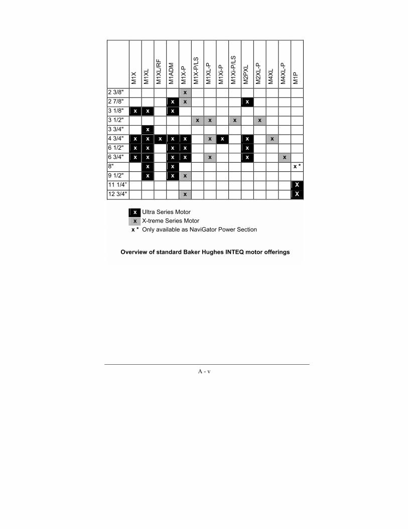
A - v
M1X
M1X
L
M1X
L/R
F
M1A
DM
M1X
-P
M1X
-P/L
S
M1X
L-P
M1X
i-P
M1X
i-P/L
S
M2P
XL
M2X
L-P
M4X
L
M4X
L-P
M1P
2 3/8" x 2 7/8" x x x 3 1/8" x x x 3 1/2" x x x x 3 3/4" x 4 3/4" x x x x x x x x x 6 1/2" x x x x x 6 3/4" x x x x x x x 8" x x x * 9 1/2" x x x 11 1/4� X 12 3/4" x X
x Ultra Series Motor x X-treme Series Motor x * Only available as NaviGator Power Section
Overview of standard Baker Hughes INTEQ motor offerings

A - 1
2-7/8" M1ADM Ultra Series Motor
General Tool Specifications Length: 12.17 ft (3.71 m) Weight: 203 lbs (92 kg) Top Connection: 2-3/8" PAC DSI (optional 3" CDP) Bit Connection: 2-3/8" API Reg. Box Max. OD (at Wear Pad): 3.19 inch (81 mm) Bearing Type: Mud lubricated Bearing Section Drive Mechanism: Mud Flow
Performance Data Lobe Configuration: 5/6 Flow Rate: 25 - 120 gpm (100 - 450 l/min) Speed: 40 - 185 RPM Operating Differential Pressure: 290 psi (20 bar) Operating Torque: 360 ft-lbs (490 Nm) Maximum Differential Pressure: 460 psi (32 bar) Maximum Torque: 580 ft-lbs (785 Nm) Power Output: 13 HP (10 kW) No Load Pressure: 160 psi (11 bar) Rotor Nozzle: No Maximum Flow Rate w/ Nozzle: - Operated with Air: Flow Rate: 550 scfm (16 nm³/min) Speed: 295 - 850 RPM Operating Differential Pressure: 230 psi (16 bar) Operating Torque: 310 ft-lbs (420 Nm) Maximum Differential Pressure: 370 psi (26 bar) Maximum Torque: 495 ft-lbs (670 Nm) Power Output: 17 HP (13 kW)
Operational Data Maximum WOB: 7,200 lbs (32 kN) Operating WOB: 4,720 lbs (21 kN) Defl. Device Type: Adjustable Defl. Angle: 0° - 3,8°
Maximum DLS and String Rotation: Depends on AKO setting, stabilization, hole size
Mud Type Limitation: No general limitation (in case of uncommon mud system a rubber/mud compatibility test is recommended)
Temperature (Stator System D): 265°F (130°C) Temperature (Stator System F): 320°F (160°C) Maximum Sand Content: 1 %

A - 2
2-7/8" M2PXL Ultra Series Motor General Tool Specifications
Length: 17.0 ft (5.19 m) Weight: 238 lbs (108kg) Top Connection: 2-3/8" PAC DSI (optional 3" CDP) Bit Connection: 2-3/8" API Reg. Box Max. OD (at Wear Pad): 3.19 inch (81 mm) Bearing Type: Mud lubricated Bearing Section Drive Mechanism: Mud Flow
Performance Data
Lobe Configuration: 2/3 Flow Rate: 53 - 106 gpm (200 - 400 l/min) Speed: 415 - 830 RPM Operating Differential Pressure: 1,305 psi (90 bar) Operating Torque: 345 ft-lbs (465 Nm) Maximum Differential Pressure: 2,090 psi (144 bar) Maximum Torque: 550 ft-lbs (745 Nm) Power Output: 52 HP (39 kW) No Load Pressure: 160 psi (16 bar) Rotor Nozzle: No Maximum Flow Rate w/ Nozzle: -
Operational Data
Maximum WOB: 7,200 lbs (32 kN) Operating WOB: 4,720 lbs (21 kN) Defl. Device Type: Adjustable Defl. Angle: 0° - 3,8°
Maximum DLS and String Rotation: Depends on AKO setting, stabilization, hole size
Mud Type Limitation: No general limitation (in case of uncommon mud system a rubber/mud compatibility test is recommended)
Temperature (Stator System D): 265°F (130°C) Temperature (Stator System F): 320°F (160°C) Maximum Sand Content: 1 %

A - 3
3-1/8" M1X Ultra Series Motor General Tool Specifications
Length: 12.1 ft (3.7 m) Weight: 220 lbs (100 kg) Top Connection: 2-3/8" API Reg. Box Bit Connection: 2-3/8" API Reg. Box
(optional 2-7/8� API Reg. Box on 3-3/4" OD Drive Sub)
Max. OD (at Wear Pad): 3.35 inch (85 mm) at Wear Ring 3.40 inch (86.3 mm) at Bearing Assy
Bearing Type: Mud lubricated Bearing Section Drive Mechanism: Mud Flow
Performance Data
Lobe Configuration: 5/6 Flow Rate: 80 - 160 gpm (300 - 600 l/min) Speed: 180 - 365 RPM Operating Differential Pressure: 460 psi (32 bar) Operating Torque: 380 ft-lbs (520 Nm) Maximum Differential Pressure: 740 psi (51 bar) Maximum Torque: 610 ft-lbs (830 Nm) Power Output: 27 HP (20 kW) No Load Pressure: 145 psi (10 bar) Rotor Nozzle: No Maximum Flow Rate w/ Nozzle: -
Operational Data
Maximum WOB: 10,100 lbs (45 kN) Operating WOB: 6,700 lbs (30 kN) Defl. Device Type: Adjustable Defl. Angle: 0° - 3,2°
Maximum DLS and String Rotation: Depends on AKO setting, stabilization, hole size
Mud Type Limitation: No general limitation (in case of uncommon mud system a rubber/mud compatibility test is recommended)
Temperature (Stator System D): 265°F (130°C) Temperature (Stator System F): 320°F (160°C) Maximum Sand Content: 1 %

A - 4
3-1/8" M1XL Ultra Series Motor General Tool Specifications
Length: 16.7 ft (5.1 m) Weight: 330 lbs (150 kg) Top Connection: 2-3/8" API Reg. Box Bit Connection: 2-3/8" API Reg. Box
(optional 2-7/8� API Reg. Box on 3-3/4" OD Drive Sub)
Max. OD (at Wear Pad): 3.35 inch (85 mm) at Wear Ring 3.40 inch (86.3 mm) at Bearing Assy
Bearing Type: Mud lubricated Bearing Section Drive Mechanism: Mud Flow
Performance Data
Lobe Configuration: 5/6 Flow Rate: 80 - 160 gpm (300 - 600 l/min) Speed: 180 - 365 RPM Operating Differential Pressure: 870 psi (60 bar) Operating Torque: 720 ft-lbs (975 Nm) Maximum Differential Pressure: 1,390 (psi) (96 bar) Maximum Torque: 1,150 ft-lbs (1,560 Nm) Power Output: 50 HP (37 kW) No Load Pressure: 290 psi (20 bar) Rotor Nozzle: No Maximum Flow Rate w/ Nozzle: -
Operational Data
Maximum WOB: 10,100 lbs (45 kN) Operating WOB: 6,700 lbs (30 kN) Defl. Device Type: Adjustable Defl. Angle: 0° - 3,2°
Maximum DLS and String Rotation: Depends on AKO setting, stabilization, hole size
Mud Type Limitation: No general limitation (in case of uncommon mud system a rubber/mud compatibility test is recommended)
Temperature (Stator System D): 265°F (130°C) Temperature (Stator System F): 320°F (160°C) Maximum Sand Content: 1 %

A - 5
3-1/8" M1ADM Ultra Series Motor General Tool Specifications
Length: 16.7 ft (5.1 m) Weight: 330 lbs (150 kg) Top Connection: 2-3/8" API Reg. Box Bit Connection: 2-3/8" API Reg. Box
(optional 2-7/8� API Reg. Box on 3-3/4" OD Drive Sub)
Max. OD (at Wear Pad): 3.35 inch (85 mm) at Wear Ring 3.40 inch (86.3 mm) at Bearing Assy
Bearing Type: Mud lubricated Bearing Section Drive Mechanism: Mud Flow
Performance Data Lobe Configuration: 5/6 Flow Rate: 80 - 160 gpm (300 - 600 l/min) Speed: 65 - 125 RPM Operating Differential Pressure: 290 psi (20 bar) Operating Torque: 710 ft-lbs (960 Nm) Maximum Differential Pressure: 460 psi (32 bar) Maximum Torque: 1,135 ft-lbs (1,540 Nm) Power Output: 17 HP (13 kW) No Load Pressure: 190 psi (13 bar) Rotor Nozzle: No Maximum Flow Rate w/ Nozzle: - Operated with Air: Flow Rate: 700 scfm (20 nm³/min) Speed: 185 - 540 RPM Operating Differential Pressure: 230 psi (16 bar) Operating Torque: 600 ft-lbs (820 Nm) Maximum Differential Pressure: 370 psi (26 bar) Maximum Torque: 960 ft-lbs (1,310 Nm) Power Output: 21 HP (16 kW)
Operational Data Maximum WOB: 10,100 lbs (45 kN) Operating WOB: 6,700 lbs (30 kN) Defl. Device Type: adjustable Defl. Angle: 0° - 3,2°
Maximum DLS and String Rotation: Depends on AKO setting, stabilization, hole size
Mud Type Limitation: No general limitation (in case of uncommon mud system a rubber/mud compatibility test is recommended)
Temperature (Stator System D): 265°F (130°C) Temperature (Stator System F): 320°F (160°C) Maximum Sand Content: 1 %

A - 6
3-3/4" M1XL Ultra Series Motor General Tool Specifications
Length: 28.5 ft (8.7 m) Weight: 860 lbs (390 kg)
Top Connection: 2-7/8" AOH (optional 2-7/8" SL H90, NC 26)
Bit Connection: 2-7/8" API Reg. Box Max. OD (at Wear Pad): 4.1 inch (105 mm) Bearing Type: Mud lubricated Bearing Section Drive Mechanism: Mud Flow
Performance Data
Lobe Configuration: 5/6 Flow Rate: 80 - 210 gpm (300 - 800 l/min) Speed: 150 - 410 RPM Operating Differential Pressure: 1,600 psi (110 bar) Operating Torque: 1,620 ft-lbs (2,200 Nm) Maximum Differential Pressure: 2,550 psi (176 bar) Maximum Torque: 2,590 ft-lbs (3,520 Nm) Power Output: 126 HP (94 kW) No Load Pressure: 318 psi (22 bar) Rotor Nozzle: No Maximum Flow Rate w/ Nozzle: -
Operational Data
Maximum WOB: 14,600 lbs (65 kN) Operating WOB: 10,100 lbs (45 kN) Defl. Device Type: adjustable Defl. Angle: 0° - 3,2°
Maximum DLS and String Rotation: Depends on AKO setting, stabilization, hole size
Mud Type Limitation: No general limitation (in case of uncommon mud system a rubber/mud compatibility test is recommended)
Temperature (Stator System D): 265°F (130°C) Temperature (Stator System F): 320°F (160°C) Maximum Sand Content: 1 %

A - 7
4-3/4" M1X Ultra Series Motor General Tool Specifications
Length: 20.7 ft (6.3 m) Weight: 800 lbs (360 kg) Top Connection: NC 38 Bit Connection: 3-1/2" API Reg. Box Max. OD (at Wear Pad): 5.1 inch (130 mm) Bearing Type: Mud lubricated Bearing Section Drive Mechanism: Mud Flow
Performance Data
Lobe Configuration: 5/6 Flow Rate: 105 - 315 gpm (400 - 1,200 l/min) Speed: 110 - 325 RPM Operating Differential Pressure: 725 psi (50 bar) Operating Torque: 1,360 ft-lbs (1,850 Nm) Maximum Differential Pressure: 1,160 psi (80 bar) Maximum Torque: 2,180 ft-lbs (2,960 Nm) Power Output: 84 HP (63 kW) No Load Pressure: 175 psi (12 bar) Rotor Nozzle: No Maximum Flow Rate w/ Nozzle: -
Operational Data
Maximum WOB: 22,500 lbs (100 kN) Operating WOB: 14,600 lbs (65 kN) Defl. Device Type: adjustable Defl. Angle: 0° - 3,2°
Maximum DLS and String Rotation: Depends on AKO setting, stabilization, hole size
Mud Type Limitation: No general limitation (in case of uncommon mud system a rubber/mud compatibility test is recommended)
Temperature (Stator System D): 265°F (130°C) Temperature (Stator System F): 320°F (160°C) Maximum Sand Content: 1 %

A - 8
4-3/4" M1XL Ultra Series Motor General Tool Specifications
Length: 30.8 ft (9.4 m) Weight: 1,410 lbs (640 kg) Top Connection: NC 38 Bit Connection: 3-1/2" API Reg. Box Max. OD (at Wear Pad): 5.1 inch (130 mm) Bearing Type: Mud lubricated Bearing Section Drive Mechanism: Mud Flow
Performance Data
Lobe Configuration: 5/6 Flow Rate: 105 - 315 gpm (400 - 1,200 l/min) Speed: 110 - 325 RPM Operating Differential Pressure: 1,380 psi (95 bar) Operating Torque: 2,600 ft-lbs (3,530 Nm) Maximum Differential Pressure: 2,200 psi (152 bar) Maximum Torque: 4,165 ft-lbs (5,650 Nm) Power Output: 161 HP (120 kW) No Load Pressure: 305 psi (21 bar) Rotor Nozzle: No Maximum Flow Rate w/ Nozzle: -
Operational Data
Maximum WOB: 27,500 lbs (100 kN) Operating WOB: 14,600 lbs (65 kN) Defl. Device Type: adjustable Defl. Angle: 0° - 3,2°
Maximum DLS and String Rotation: Depends on AKO setting, stabilization, hole size
Mud Type Limitation: No general limitation (in case of uncommon mud system a rubber/mud compatibility test is recommended)
Temperature (Stator System D): 265°F (130°C) Temperature (Stator System F): 320°F (160°C) Maximum Sand Content: 1 %

A - 9
4-3/4" M1XL/RF Ultra Series Motor General Tool Specifications
Length: 30.8 ft (9.4 m) Weight: 1,410 lbs (640 kg) Top Connection: NC 38 Bit Connection: 3-1/2" API Reg. Box Max. OD (at Wear Pad): 5.1 inch (130 mm) Bearing Type: Mud lubricated Bearing Section Drive Mechanism: Mud Flow
Performance Data
Lobe Configuration: 4/5 Flow Rate: 120 - 225 gpm (450 - 850 l/min) Speed: 175 - 335 RPM Operating Differential Pressure: 1,810 psi (125 bar) Operating Torque: 2,350 ft-lbs (3,200 Nm) Maximum Differential Pressure: 2,900 psi (200 bar) Maximum Torque: 3,760 ft-lbs (5,120 Nm) Power Output: 150 HP (112 kW) No Load Pressure: 405 psi (28 bar) Rotor Nozzle: No Maximum Flow Rate w/ Nozzle: -
Operational Data
Maximum WOB: 22,500 lbs (100 kN) Operating WOB: 14,600 lbs (65 kN) Defl. Device Type: adjustable Defl. Angle: 0° - 3,2°
Maximum DLS and String Rotation: Depends on AKO setting, stabilization, hole size
Mud Type Limitation: No general limitation (in case of uncommon mud system a rubber/mud compatibility test is recommended)
Temperature (Stator System D): 265°F (130°C) Temperature (Stator System F): 320°F (160°C) Maximum Sand Content: 1 %

A - 10
4-3/4" M1ADM Ultra Series Motor General Tool Specifications
Length: 22.0 ft (6.7 m) Weight: 840 lbs (380 kg) Top Connection: NC 38 Bit Connection: 3-1/2" API Reg. Box Max. OD (at Wear Pad): 5.1 inch (130 mm) Bearing Type: Mud lubricated Bearing Section Drive Mechanism: Mud Flow
Performance Data Lobe Configuration: 5/6 Flow Rate: 160 - 315 gpm (600 - 1,200 l/min) Speed: 55 - 110 RPM Operating Differential Pressure: 290 psi (20 bar) Operating Torque: 1,620 ft-lbs (2,200 Nm) Maximum Differential Pressure: 460 psi (32 bar) Maximum Torque: 2,590 ft-lbs (3,520 Nm) Power Output: 34 HP (25 kW) No Load Pressure: 190 psi (13 bar) Rotor Nozzle: No Maximum Flow Rate w/ Nozzle: - Operated with Air: Flow Rate: 1,500 scfm (43 nm³/min) Speed: 165 - 490 RPM Operating Differential Pressure: 230 psi (16 bar) Operating Torque: 1,390 ft-lbs (1,890 Nm) Maximum Differential Pressure: 370 psi (26 bar) Maximum Torque: 2,225 ft-lbs (3,025 Nm) Power Output: 44 HP (33 kW)
Operational Data Maximum WOB: 22,500 lbs (100 kN) Operating WOB: 14,600 lbs (65 kN) Defl. Device Type: adjustable Defl. Angle: 0° - 3,2°
Maximum DLS and String Rotation: Depends on AKO setting, stabilization, hole size
Mud Type Limitation: No general limitation (in case of uncommon mud system a rubber/mud compatibility test is recommended)
Temperature (Stator System D): 265°F (130°C) Temperature (Stator System F): 320°F (160°C) Maximum Sand Content: 1 %
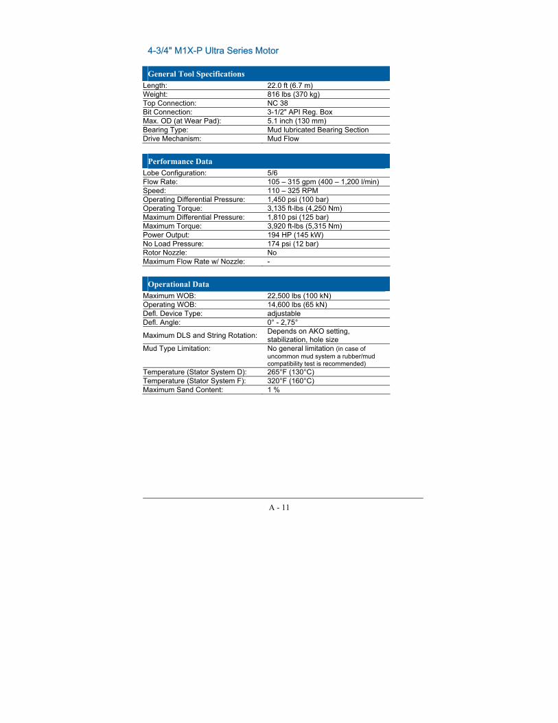
A - 11
4-3/4" M1X-P Ultra Series Motor General Tool Specifications
Length: 22.0 ft (6.7 m) Weight: 816 lbs (370 kg) Top Connection: NC 38 Bit Connection: 3-1/2" API Reg. Box Max. OD (at Wear Pad): 5.1 inch (130 mm) Bearing Type: Mud lubricated Bearing Section Drive Mechanism: Mud Flow
Performance Data
Lobe Configuration: 5/6 Flow Rate: 105 � 315 gpm (400 � 1,200 l/min) Speed: 110 � 325 RPM Operating Differential Pressure: 1,450 psi (100 bar) Operating Torque: 3,135 ft-lbs (4,250 Nm) Maximum Differential Pressure: 1,810 psi (125 bar) Maximum Torque: 3,920 ft-lbs (5,315 Nm) Power Output: 194 HP (145 kW) No Load Pressure: 174 psi (12 bar) Rotor Nozzle: No Maximum Flow Rate w/ Nozzle: -
Operational Data
Maximum WOB: 22,500 lbs (100 kN) Operating WOB: 14,600 lbs (65 kN) Defl. Device Type: adjustable Defl. Angle: 0° - 2,75°
Maximum DLS and String Rotation: Depends on AKO setting, stabilization, hole size
Mud Type Limitation: No general limitation (in case of uncommon mud system a rubber/mud compatibility test is recommended)
Temperature (Stator System D): 265°F (130°C) Temperature (Stator System F): 320°F (160°C) Maximum Sand Content: 1 %

A - 12
4-3/4" M1Xi-P Ultra Series Motor General Tool Specifications
Length: 8.26 ft (2.5 m) Weight: 476 lbs (216 kg) Top Connection: NC-38 Bit Connection: 3-1/2" Regular Max. OD (at Wear Pad): Depends on Wear Ring1 Bearing Type: Mud lubricated Bearing Section Drive Mechanism: Mud Flow
Performance Data
Lobe Configuration: 5/6 Flow Rate: 105 - 315 gpm (400 - 1,200 l/min) Speed: 110 - 325 RPM Operating Differential Pressure: 325 psi (22.5 bar) Operating Torque: 705 ft-lbs (955 Nm) Maximum Differential Pressure: 435 psi (30 bar) Maximum Torque: 940 ft-lbs (1,275 Nm) Power Output: 44 HP (33 kW) No Load Pressure: 145 psi (10 bar) Rotor Nozzle: No Maximum Flow Rate w/ Nozzle: -
Operational Data
Maximum WOB: 13,500 lbs (60 kN) Operating WOB: 8,990 lbs (40 kN) Defl. Device Type: adjustable Defl. Angle: 0° - 3.6°
Maximum DLS and String Rotation: Depends on AKO setting, stabilization, hole size
Mud Type Limitation: No general limitation (in case of uncommon mud system a rubber/mud compatibility test is recommended)
Temperature (Stator System D): 265°F (130°C) Temperature (Stator System F): 320°F (160°C) Maximum Sand Content: 1 %

A - 13
4-3/4" M2PXL Ultra Series Motor General Tool Specifications
Length: 30.8 ft (9.4 m) Weight: 1,410 lbs (640 kg) Top Connection: NC 38 Bit Connection: 3-1/2" API Reg. Box Max. OD (at Wear Pad): 5.1 inch (130 mm) Bearing Type: Mud lubricated Bearing Section Drive Mechanism: Mud Flow
Performance Data
Lobe Configuration: 2/3 Flow Rate: 80 - 265 gpm (300 - 1,000 l/min) Speed: 180 - 600 RPM Operating Differential Pressure: 1,600 psi (110 bar) Operating Torque: 1,440 ft-lbs (1,950 Nm) Maximum Differential Pressure: 2,550 psi (176 bar) Maximum Torque: 2,300 ft-lbs (3,120 Nm) Power Output: 165 HP (123 kW) No Load Pressure: 190 psi (13 bar) Rotor Nozzle: No Maximum Flow Rate w/ Nozzle: -
Operational Data
Maximum WOB: 22,500 lbs (100 kN) Operating WOB: 14,600 lbs (65 kN) Defl. Device Type: Adjustable Defl. Angle: 0° - 3,2°
Maximum DLS and String Rotation: Depends on AKO setting, stabilization, hole size
Mud Type Limitation: No general limitation (in case of uncommon mud system a rubber/mud compatibility test is recommended)
Temperature (Stator System D): 265°F (130°C) Temperature (Stator System F): 320°F (160°C) Maximum Sand Content: 1 %

A - 14
6-1/2" M1X Ultra Series Motor General Tool Specifications
Length: 23.0 ft (7.0 m) Weight: 1,765 lbs (800 kg) Top Connection: NC 50 Bit Connection: 4-1/2" API Reg. Box Max. OD (at Wear Pad): 7.1 inch (180 mm) Bearing Type: Mud lubricated Bearing Section Drive Mechanism: Mud Flow
Performance Data
Lobe Configuration: 5/6
Flow Rate: 265 - 660 gpm (1,000 - 2,500 l/min)
Speed: 90 - 220 RPM Operating Differential Pressure: 460 psi (32 bar) Operating Torque: 2,690 ft-lbs (3,650 Nm) Maximum Differential Pressure: 740 psi (51 bar) Maximum Torque: 4,300 ft-lbs (5,840 Nm) Power Output: 113 HP (84 kW) No Load Pressure: 220 psi (15 bar) Rotor Nozzle: Yes Maximum Flow Rate w/ Nozzle: 725 gpm (2,750 l/min)
Operational Data
Maximum WOB: 36,000 lbs (160 kN) Operating WOB: 23,600 lbs (105 kN) Defl. Device Type: adjustable Defl. Angle: 0° - 2,75°
Maximum DLS and String Rotation: Depends on AKO setting, stabilization, hole size
Mud Type Limitation: No general limitation (in case of uncommon mud system a rubber/mud compatibility test is recommended)
Temperature (Stator System D): 265°F (130°C) Temperature (Stator System F): 320°F (160°C) Maximum Sand Content: 1 %
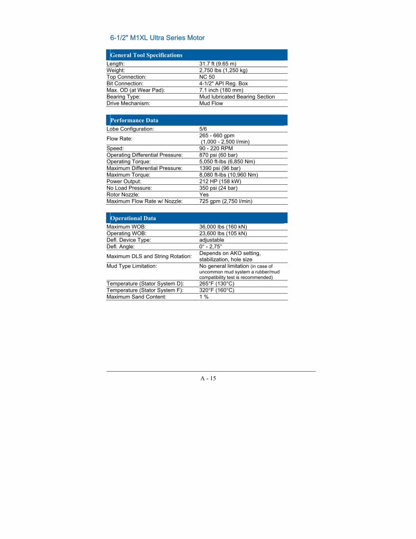
A - 15
6-1/2" M1XL Ultra Series Motor General Tool Specifications
Length: 31.7 ft (9.65 m) Weight: 2,750 lbs (1,250 kg) Top Connection: NC 50 Bit Connection: 4-1/2" API Reg. Box Max. OD (at Wear Pad): 7.1 inch (180 mm) Bearing Type: Mud lubricated Bearing Section Drive Mechanism: Mud Flow
Performance Data
Lobe Configuration: 5/6
Flow Rate: 265 - 660 gpm (1,000 - 2,500 l/min)
Speed: 90 - 220 RPM Operating Differential Pressure: 870 psi (60 bar) Operating Torque: 5,050 ft-lbs (6,850 Nm) Maximum Differential Pressure: 1390 psi (96 bar) Maximum Torque: 8,080 ft-lbs (10,960 Nm) Power Output: 212 HP (158 kW) No Load Pressure: 350 psi (24 bar) Rotor Nozzle: Yes Maximum Flow Rate w/ Nozzle: 725 gpm (2,750 l/min)
Operational Data
Maximum WOB: 36,000 lbs (160 kN) Operating WOB: 23,600 lbs (105 kN) Defl. Device Type: adjustable Defl. Angle: 0° - 2,75°
Maximum DLS and String Rotation: Depends on AKO setting, stabilization, hole size
Mud Type Limitation: No general limitation (in case of uncommon mud system a rubber/mud compatibility test is recommended)
Temperature (Stator System D): 265°F (130°C) Temperature (Stator System F): 320°F (160°C) Maximum Sand Content: 1 %

A - 16
6-1/2" M1ADM Ultra Series Motor General Tool Specifications
Length: 23.0 ft (7.0 m) Weight: 1,765 lbs (800 kg) Top Connection: NC 50 Bit Connection: 4-1/2" API Reg. Box Max. OD (at Wear Pad): 7.1 inch (180 mm) Bearing Type: Mud lubricated Bearing Section Drive Mechanism: Mud Flow
Performance Data Lobe Configuration: 7/8
Flow Rate: 345 - 610 gpm (1,300 - 2,300 l/min)
Speed: 50 - 95 RPM Operating Differential Pressure: 350 psi (24 bar) Operating Torque: 4,300 ft-lbs (5,800 Nm) Maximum Differential Pressure: 557 psi (38 bar) Maximum Torque: 6,880 ft-lbs (9,280 Nm) Power Output: 76 HP (57 kW) No Load Pressure: 220 psi (15 bar) Rotor Nozzle: Yes Maximum Flow Rate w/ Nozzle: 725 gpm (2,750 l/min) Operated with Air: Flow Rate: 2,100 scfm (60 nm³/min) Speed: 110 - 325 RPM Operating Differential Pressure: 230 psi (16 bar) Operating Torque: 3,100 ft-lbs (4,200 Nm) Maximum Differential Pressure: 370 psi (26 bar) Maximum Torque: 4,960 ft-lbs (6,720 Nm) Power Output: 65 HP (48 kW)
Operational Data Maximum WOB: 36,000 lbs (160 kN) Operating WOB: 23,600 lbs (105 kN) Defl. Device Type: adjustable Defl. Angle: 0° - 2,75°
Maximum DLS and String Rotation: Depends on AKO setting, stabilization, hole size
Mud Type Limitation: No general limitation (in case of uncommon mud system a rubber/mud compatibility test is recommended)
Temperature (Stator System D): 265°F (130°C) Temperature (Stator System F): 320°F (160°C) Maximum Sand Content: 1 %

A - 17
6-1/2" M1X-P Ultra Series Motor General Tool Specifications
Length: 23.0 ft (7.0 m) Weight: 1,765 lbs (800 kg) Top Connection: NC 50 Bit Connection: 4-1/2" API Reg. Box Max. OD (at Wear Pad): 7.3 inch (185 mm) Bearing Type: Mud lubricated Bearing Section Drive Mechanism: Mud Flow
Performance Data
Lobe Configuration: 5/6
Flow Rate: 265 - 660 gpm (1,000 - 2,500 l/min)
Speed: 90 - 220 RPM Operating Differential Pressure: 870 psi (60 bar) Operating Torque: 5,780 ft-lbs (7,840 Nm) Maximum Differential Pressure: 1,090 psi (75 bar) Maximum Torque: 7,225 ft-lbs (9,800 Nm) Power Output: 242 HP (180 kW) No Load Pressure: 220 psi (15 bar) Rotor Nozzle: Yes Maximum Flow Rate w/ Nozzle: 726 gpm (2,750 l/min)
Operational Data
Maximum WOB: 36,000 lbs (160 kN) Operating WOB: 23,600 lbs (105 kN) Defl. Device Type: adjustable Defl. Angle: 0° - 2,75°
Maximum DLS and String Rotation: Depends on AKO setting, stabilization, hole size
Mud Type Limitation: No general limitation (in case of uncommon mud system a rubber/mud compatibility test is recommended)
Temperature (Stator System D): 265°F (130°C) Temperature (Stator System F): 320°F (160°C) Maximum Sand Content: 1 %

A - 18
6-1/2" M2PXL Ultra Series Motor General Tool Specifications
Length: 31.7 ft (9.65 m) Weight: 2,750 lbs (1,250 kg) Top Connection: NC 50 Bit Connection: 4-1/2" API Reg. Box Max. OD (at Wear Pad): 7.3 inch (185 mm) Bearing Type: Mud lubricated Bearing Section Drive Mechanism: Mud Flow
Performance Data
Lobe Configuration: 2/3
Flow Rate: 265 - 530 gpm (1,000 - 2,000 l/min)
Speed: 235 - 470 RPM Operating Differential Pressure: 1,160 psi (80 bar) Operating Torque: 2,690 ft-lbs (3,650 Nm) Maximum Differential Pressure: 1,856 psi (128 bar) Maximum Torque: 4,300 ft-lbs (5,840 Nm) Power Output: 240 HP (180 kW) No Load Pressure: 205 psi (14 bar) Rotor Nozzle: No Maximum Flow Rate w/ Nozzle: -
Operational Data
Maximum WOB: 36,000 lbs (160 kN) Operating WOB: 23,600 lbs (105 kN) Defl. Device Type: adjustable Defl. Angle: 0° - 2,75°
Maximum DLS and String Rotation: Depends on AKO setting, stabilization, hole size
Mud Type Limitation: No general limitation (in case of uncommon mud system a rubber/mud compatibility test is recommended)
Temperature (Stator System D): 265°F (130°C) Temperature (Stator System F): 320°F (160°C) Maximum Sand Content: 1 %

A - 19
6-3/4" M1X Ultra Series Motor General Tool Specifications
Length: 23.0 ft (7.0 m) Weight: 1,765 lbs (800 kg) Top Connection: NC 50 Bit Connection: 4-1/2" API Reg. Box Max. OD (at Wear Pad): 7.3 inch (185 mm) Bearing Type: Mud lubricated Bearing Section Drive Mechanism: Mud Flow
Performance Data
Lobe Configuration: 5/6
Flow Rate: 265 - 660 gpm (1,000 - 2,500 l/min)
Speed: 90 - 220 RPM Operating Differential Pressure: 460 psi (32 bar) Operating Torque: 2,690 ft-lbs (3,650 Nm) Maximum Differential Pressure: 740 psi (51 bar) Maximum Torque: 4,300 ft-lbs (5,840 Nm) Power Output: 113 HP (84 kW) No Load Pressure: 220 psi (15 bar) Rotor Nozzle: Yes Maximum Flow Rate w/ Nozzle: 725 gpm (2,750 l/min)
Operational Data
Maximum WOB: 36,000 lbs (160 kN) Operating WOB: 23,600 lbs (105 kN) Defl. Device Type: adjustable Defl. Angle: 0° - 2,75°
Maximum DLS and String Rotation: Depends on AKO setting, stabilization, hole size
Mud Type Limitation: No general limitation (in case of uncommon mud system a rubber/mud compatibility test is recommended)
Temperature (Stator System D): 265°F (130°C) Temperature (Stator System F): 320°F (160°C) Maximum Sand Content: 1 %

A - 20
6-3/4" M1XL Ultra Series Motor General Tool Specifications
Length: 31.7 ft (9.65 m) Weight: 2,750 lbs (1,250 kg) Top Connection: NC 50 Bit Connection: 4-1/2" API Reg. Box Max. OD (at Wear Pad): 7.3 inch (185 mm) Bearing Type: Mud lubricated Bearing Section Drive Mechanism: Mud Flow
Performance Data
Lobe Configuration: 5/6
Flow Rate: 265 - 660 gpm (1,000 - 2,500 l/min)
Speed: 90 - 220 RPM Operating Differential Pressure: 870 psi (60 bar) Operating Torque: 5,050 ft-lbs (6,850 Nm) Maximum Differential Pressure: 1,390 psi (96 bar) Maximum Torque: 8,080 ft-lbs (10,960 Nm) Power Output: 212 HP (158 kW) No Load Pressure: 350 psi (24 bar) Rotor Nozzle: Yes Maximum Flow Rate w/ Nozzle: 725 gpm (2,750 l/min)
Operational Data
Maximum WOB: 36,000 lbs (160 kN) Operating WOB: 23,600 lbs (105 kN) Defl. Device Type: adjustable Defl. Angle: 0° - 2,75°
Maximum DLS and String Rotation: Depends on AKO setting, stabilization, hole size
Mud Type Limitation: No general limitation (in case of uncommon mud system a rubber/mud compatibility test is recommended)
Temperature (Stator System D): 265°F (130°C) Temperature (Stator System F): 320°F (160°C) Maximum Sand Content: 1 %

A - 21
6-3/4" M1ADM Ultra Series Motor General Tool Specifications
Length: 23.0 ft (7.0 m) Weight: 1,765 lbs (800 kg) Top Connection: NC 50 Bit Connection: 4-1/2" API Reg. Box Max. OD (at Wear Pad): 7.3 inch (185 mm) Bearing Type: Mud lubricated Bearing Section Drive Mechanism: Mud Flow
Performance Data
Lobe Configuration: 7/8
Flow Rate: 345 - 610 gpm (1,300 - 2,300 l/min)
Speed: 50 - 95 RPM Operating Differential Pressure: 350 psi (24 bar) Operating Torque: 4,300 ft-lbs (5,800 Nm) Maximum Differential Pressure: 557 psi (38 bar) Maximum Torque: 6,880 ft-lbs (9,280 Nm) Power Output: 76 HP (57 kW) No Load Pressure: 220 psi (15 bar) Rotor Nozzle: Yes Maximum Flow Rate w/ Nozzle: 725 gpm (2,750 l/min) Operated with Air: Flow Rate: 2,100 scfm (60 nm³/min) Speed: 110 - 325 RPM Operating Differential Pressure: 230 psi (16 bar) Operating Torque: 3,100 ft-lbs (4,200 Nm) Maximum Differential Pressure: 370 psi (26 bar) Maximum Torque: 4,960 ft-lbs (6,720 Nm) Power Output: 65 HP (48 kW)
Operational Data
Maximum WOB: 36,000 lbs (160 kN) Operating WOB: 23,600 lbs (105 kN) Defl. Device Type: adjustable Defl. Angle: 0° - 2,75°
Maximum DLS and String Rotation: Depends on AKO setting, stabilization, hole size
Mud Type Limitation: No general limitation (in case of uncommon mud system a rubber/mud compatibility test is recommended)
Temperature (Stator System D): 265°F (130°C) Temperature (Stator System F): 320°F (160°C) Maximum Sand Content: 1 %

A - 22
6-3/4" M1X-P Ultra Series Motor General Tool Specifications
Length: 23.0 ft (7.0 m) Weight: 1,765 lbs (800 kg) Top Connection: NC 50 Bit Connection: 4-1/2" API Reg. Box Max. OD (at Wear Pad): 7.3 inch (185 mm) Bearing Type: Mud lubricated Bearing Section Drive Mechanism: Mud Flow
Performance Data
Lobe Configuration: 5/6
Flow Rate: 265 - 660 gpm (1,000 - 2,500 l/min)
Speed: 90 - 220 RPM Operating Differential Pressure: 870 psi (60 bar) Operating Torque: 5,780 ft-lbs (7,840 Nm) Maximum Differential Pressure: 1,090 psi (75 bar) Maximum Torque: 7,225 ft-lbs (9,800 Nm) Power Output: 242 HP (180 kW) No Load Pressure: 220 psi (15 bar) Rotor Nozzle: Yes Maximum Flow Rate w/ Nozzle: 726 gpm (2,750 l/min)
Operational Data
Maximum WOB: 36,000 lbs (160 kN) Operating WOB: 23,600 lbs (105 kN) Defl. Device Type: adjustable Defl. Angle: 0° - 2,75°
Maximum DLS and String Rotation: Depends on AKO setting, stabilization, hole size
Mud Type Limitation: No general limitation (in case of uncommon mud system a rubber/mud compatibility test is recommended)
Temperature (Stator System D): 265°F (130°C) Temperature (Stator System F): 320°F (160°C) Maximum Sand Content: 1 %

A - 23
6-3/4" M2PXL Ultra Series Motor General Tool Specifications
Length: 31.7 ft (9.65 m) Weight: 2,750 lbs (1,250 kg) Top Connection: NC 50 Bit Connection: 4-1/2" API Reg. Box Max. OD (at Wear Pad): 7.3 inch (185 mm) Bearing Type: Mud lubricated Bearing Section Drive Mechanism: Mud Flow
Performance Data
Lobe Configuration: 2/3
Flow Rate: 265 - 530 gpm (1,000 - 2,000 l/min)
Speed: 235 - 470 RPM Operating Differential Pressure: 1,160 psi (80 bar) Operating Torque: 2,690 ft-lbs (3,650 Nm) Maximum Differential Pressure: 1,856 psi (128 bar) Maximum Torque: 4,300 ft-lbs (5,840 Nm) Power Output: 240 HP (180 kW) No Load Pressure: 205 psi (14 bar) Rotor Nozzle: No Maximum Flow Rate w/ Nozzle: -
Operational Data
Maximum WOB: 36,000 lbs (160 kN) Operating WOB: 23,600 lbs (105 kN) Defl. Device Type: adjustable Defl. Angle: 0° - 2,75°
Maximum DLS and String Rotation: Depends on AKO setting, stabilization, hole size
Mud Type Limitation: No general limitation (in case of uncommon mud system a rubber/mud compatibility test is recommended)
Temperature (Stator System D): 265°F (130°C) Temperature (Stator System F): 320°F (160°C) Maximum Sand Content: 1 %

A - 24
8" M1XL Ultra Series Motor General Tool Specifications
Length: 34.77 ft (10.65 m) Weight: 4,080 lbs (1,850 kg) Top Connection: 6-5/8" API Reg. Box Bit Connection: 6-5/8" API Reg. Box Max. OD (at Wear Pad): 8.5 inch (217 mm) Bearing Type: Mud lubricated Bearing Section Drive Mechanism: Mud Flow
Performance Data
Lobe Configuration: 5/6
Flow Rate: 395 - 900 gpm (1,500 - 3,400 l/min)
Speed: 85 - 195 RPM Operating Differential Pressure: 870 psi (60 bar) Operating Torque: 7,670 ft-lbs (10,400 Nm) Maximum Differential Pressure: 1390 psi (96 bar) Maximum Torque: 12,270 ft-lbs (16,640 Nm) Power Output: 285 HP (213 kW) No Load Pressure: 300 psi (21 bar) Rotor Nozzle: Yes Maximum Flow Rate w/ Nozzle: 990 gpm (3,750 l/min)
Operational Data
Maximum WOB: 67,400 lbs (300 kN) Operating WOB: 45,000 lbs (200 kN) Defl. Device Type: adjustable Defl. Angle: 0° - 2,5°
Maximum DLS and String Rotation: Depends on AKO setting, stabilization, hole size
Mud Type Limitation: No general limitation (in case of uncommon mud system a rubber/mud compatibility test is recommended)
Temperature (Stator System D): 265°F (130°C) Temperature (Stator System F): 320°F (160°C) Maximum Sand Content: 1 %

A - 25
8" M1ADM Ultra Series Motor General Tool Specifications
Length: 27.8 ft (8.5 m) Weight: 3,300 lbs (1,500 kg) Top Connection: 6-5/8" API Reg. Box Bit Connection: 6-5/8" API Reg. Box Max. OD (at Wear Pad): 8.5 inch (217 mm) Bearing Type: Mud lubricated Bearing Section Drive Mechanism: Mud Flow
Performance Data
Lobe Configuration: 7/8
Flow Rate: 530 - 900 gpm (2,000 - 3,400 l/min)
Speed: 50 - 80 RPM Operating Differential Pressure: 350 psi (24 bar) Operating Torque: 7,450 ft-lbs (10,100 Nm) Maximum Differential Pressure: 557 psi (38 bar) Maximum Torque: 11,920 ft-lbs (16,160 Nm) Power Output: 114 HP (85 kW) No Load Pressure: 220 psi (15 bar) Rotor Nozzle: Yes Maximum Flow Rate w/ Nozzle: 990 gpm (3,750 l/min) Operated with Air: Flow Rate: 3,000 scfm (85 nm³/min) Speed: 90 - 265 RPM Operating Differential Pressure: 230 psi (16 bar) Operating Torque: 5,320 ft-lbs (7,220 Nm) Maximum Differential Pressure: 370 psi (26 bar) Maximum Torque: 8,510 ft-lbs (11,550 Nm) Power Output: 91 HP (68 kW)
Operational Data
Maximum WOB: 67,400 lbs (300 kN) Operating WOB: 45,000 lbs (200 kN) Defl. Device Type: adjustable Defl. Angle: 0° - 2, 5°
Maximum DLS and String Rotation: Depends on AKO setting, stabilization, hole size
Mud Type Limitation: No general limitation (in case of uncommon mud system a rubber/mud compatibility test is recommended)
Temperature (Stator System D): 265°F (130°C) Temperature (Stator System F): 320°F (160°C) Maximum Sand Content: 1 %

A - 26
9-1/2" M1XL Ultra Series Motor General Tool Specifications
Length: 36.1 ft (11.0 m) Weight: 5,950 lbs (2,700 kg)
Top Connection: 6-5/8" API Reg. Box (7 5/8� API Reg. Box)
Bit Connection: 6-5/8" API Reg. Box Max. OD (at Wear Pad): 10.4 inch (265 mm) Bearing Type: Mud lubricated Bearing Section Drive Mechanism: Mud Flow
Performance Data
Lobe Configuration: 5/6
Flow Rate: 530 - 1,060 gpm (2,000 - 4,000 l/min)
Speed: 85 - 165 RPM Operating Differential Pressure: 870 psi (60 bar) Operating Torque: 10,770 ft-lbs (14,600 Nm) Maximum Differential Pressure: 1390 psi (96 bar) Maximum Torque: 17,230 ft-lbs (23,360 Nm) Power Output: 338 HP (252 kW) No Load Pressure: 260 psi (18 bar) Rotor Nozzle: Yes Maximum Flow Rate w/ Nozzle: 1,160 gpm (4,400 l/min)
Operational Data
Maximum WOB: 92,200 lbs (410 kN) Operating WOB: 60,700 lbs (270 kN) Defl. Device Type: adjustable Defl. Angle: 0° - 2,0°
Maximum DLS and String Rotation: Depends on AKO setting, stabilization, hole size
Mud Type Limitation: No general limitation (in case of uncommon mud system a rubber/mud compatibility test is recommended)
Temperature (Stator System D): 265°F (130°C) Temperature (Stator System F): 320°F (160°C) Maximum Sand Content: 1 %

A - 27
9-1/2" M1ADM Ultra Series Motor General Tool Specifications
Length: 29.2 ft (8.9 m) Weight: 5,300 lbs (2,400 kg)
Top Connection: 6-5/8" API Reg. Box (7 5/8� API Reg. Box)
Bit Connection: 6-5/8" API Reg. Box Max. OD (at Wear Pad): 10.4 inch (265 mm) Bearing Type: Mud lubricated Bearing Section Drive Mechanism: Mud Flow
Performance Data
Lobe Configuration: 7/8
Flow Rate: 660 - 1,110 gpm (2,500 - 4,200 l/min)
Speed: 40 - 70 RPM Operating Differential Pressure: 350 psi (24 bar) Operating Torque: 11,060 ft-lbs (15,000 Nm) Maximum Differential Pressure: 557 psi (38 bar) Maximum Torque: 17,700 ft-lbs (24,000 Nm) Power Output: 147 HP (110 kW) No Load Pressure: 190 psi (13 bar) Rotor Nozzle: Yes Maximum Flow Rate w/ Nozzle: 1,160 gpm (4,400 l/min) Operated with Air: Flow Rate: 3,900 scfm (110 nm³/min) Speed: 80 - 230 RPM Operating Differential Pressure: 230 psi (16 bar) Operating Torque: 7,900 ft-lbs (10,710 Nm) Maximum Differential Pressure: 370 psi (26 bar) Maximum Torque: 12,640 ft-lbs (17,140 Nm) Power Output: 120 HP (90 kW)
Operational Data
Maximum WOB: 92,200 lbs (410 kN) Operating WOB: 60,700 lbs (270 kN) Defl. Device Type: adjustable Defl. Angle: 0° - 2,0°
Maximum DLS and String Rotation: Depends on AKO setting, stabilization, hole size
Mud Type Limitation: No general limitation (in case of uncommon mud system a rubber/mud compatibility test is recommended)
Temperature (Stator System D): 265°F (130°C) Temperature (Stator System F): 320°F (160°C) Maximum Sand Content: 1 %

A - 28
11 1/4" M1P Ultra Series Motor General Tool Specifications
Length: 32 ft (9.75 m) Weight: 6,892 lbs (3,126 kg) Top Connection: 7 5/8" API Reg. Box Bit Connection: 7 5/8" API Reg. Box Max. OD (at Wear Pad): 12.09 inch (307 mm) Bearing Type: Mud lubricated Bearing Section Drive Mechanism: Mud Flow
Performance Data Lobe Configuration: 9/10
Flow Rate: 790 - 1,270 gpm (3,000 - 4,800 l/min)
Speed: 70 - 110 RPM Operating Differential Pressure: 725 psi (50 bar) Operating Torque: 17,700 ft-lbs (24,000 Nm) Maximum Differential Pressure: 1,160 psi (80 bar) Maximum Torque: 28,320 ft-lbs (38,400 Nm) Power Output: 370 HP (276 kW) No Load Pressure: 230 psi (16 bar) Rotor Nozzle: Yes Maximum Flow Rate w/ Nozzle: 1,400 gpm (5,300 l/min)
Operational Data Maximum WOB: 114,700 lbs (510 kN) Operating WOB: 75,300 lbs (335 kN) Defl. Device Type: adjustable Defl. Angle: 0° - 2,0°
Maximum DLS and String Rotation: Depends on AKO setting, stabilization, hole size
Mud Type Limitation: No general limitation (in case of uncommon mud system a rubber/mud compatibility test is recommended)
Temperature (Stator System D): 265°F (130°C) Temperature (Stator System F): 320°F (160°C) Maximum Sand Content: 1 %

A - 29
12-3/4" M1P Ultra Series Motor General Tool Specifications
Length: 34.25 ft (10.44 m) Weight: 7,165 lbs (3,250 kg) Top Connection: 7-5/8" API Reg. Box Bit Connection: 7-5/8" API Reg. Box Max. OD (at Wear Pad): 12 31/32 inch (330 mm) Bearing Type: Mud lubricated Bearing Section Drive Mechanism: Mud Flow
Performance Data
Lobe Configuration: 9/10
Flow Rate: 795 - 1,270 gpm (3,000 - 4,800 l/min)
Speed: 70 - 110 RPM Operating Differential Pressure: 725 psi (50 bar) Operating Torque: 17,700 ft-lbs (24,000 Nm) Maximum Differential Pressure: 1,160 psi (80 bar) Maximum Torque: 28,320 ft-lbs (38,400 Nm) Power Output: 371 HP (276 kW) No Load Pressure: 230 psi (16 bar) Rotor Nozzle: Yes Maximum Flow Rate w/ Nozzle: 1,400 gpm (5,300 l/min)
Operational Data
Maximum WOB: 114,700 lbs (510 kN) Operating WOB: 75,300 lbs (335 kN) Defl. Device Type: adjustable Defl. Angle: 0° - 2,0°
Maximum DLS and String Rotation: Depends on AKO setting, stabilization, hole size
Mud Type Limitation: No general limitation (in case of uncommon mud system a rubber/mud compatibility test is recommended)
Temperature (Stator System D): 265°F (130°C) Temperature (Stator System F): 320°F (160°C) Maximum Sand Content: 1 %
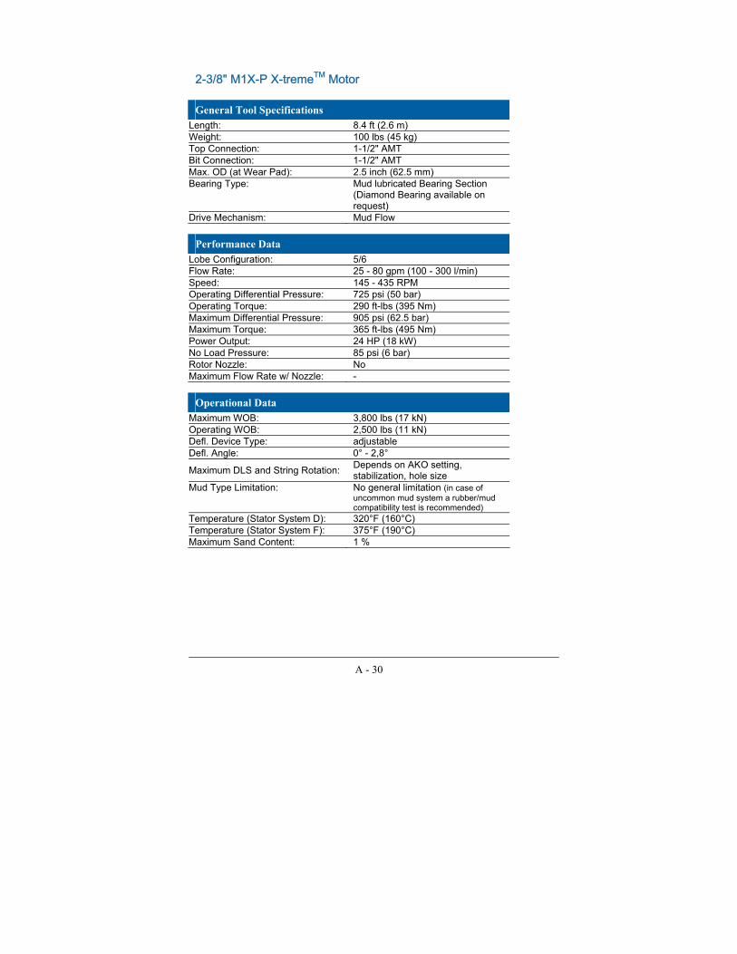
A - 30
2-3/8" M1X-P X-tremeTM Motor General Tool Specifications
Length: 8.4 ft (2.6 m) Weight: 100 lbs (45 kg) Top Connection: 1-1/2" AMT Bit Connection: 1-1/2" AMT Max. OD (at Wear Pad): 2.5 inch (62.5 mm) Bearing Type: Mud lubricated Bearing Section
(Diamond Bearing available on request)
Drive Mechanism: Mud Flow
Performance Data Lobe Configuration: 5/6 Flow Rate: 25 - 80 gpm (100 - 300 l/min) Speed: 145 - 435 RPM Operating Differential Pressure: 725 psi (50 bar) Operating Torque: 290 ft-lbs (395 Nm) Maximum Differential Pressure: 905 psi (62.5 bar) Maximum Torque: 365 ft-lbs (495 Nm) Power Output: 24 HP (18 kW) No Load Pressure: 85 psi (6 bar) Rotor Nozzle: No Maximum Flow Rate w/ Nozzle: -
Operational Data Maximum WOB: 3,800 lbs (17 kN) Operating WOB: 2,500 lbs (11 kN) Defl. Device Type: adjustable Defl. Angle: 0° - 2,8°
Maximum DLS and String Rotation: Depends on AKO setting, stabilization, hole size
Mud Type Limitation: No general limitation (in case of uncommon mud system a rubber/mud compatibility test is recommended)
Temperature (Stator System D): 320°F (160°C) Temperature (Stator System F): 375°F (190°C) Maximum Sand Content: 1 %
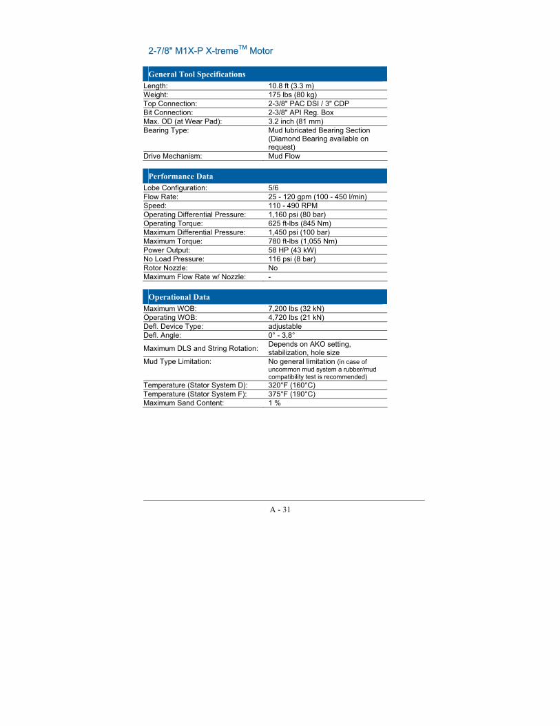
A - 31
2-7/8" M1X-P X-tremeTM Motor General Tool Specifications
Length: 10.8 ft (3.3 m) Weight: 175 lbs (80 kg) Top Connection: 2-3/8" PAC DSI / 3" CDP Bit Connection: 2-3/8" API Reg. Box Max. OD (at Wear Pad): 3.2 inch (81 mm) Bearing Type: Mud lubricated Bearing Section
(Diamond Bearing available on request)
Drive Mechanism: Mud Flow
Performance Data Lobe Configuration: 5/6 Flow Rate: 25 - 120 gpm (100 - 450 l/min) Speed: 110 - 490 RPM Operating Differential Pressure: 1,160 psi (80 bar) Operating Torque: 625 ft-lbs (845 Nm) Maximum Differential Pressure: 1,450 psi (100 bar) Maximum Torque: 780 ft-lbs (1,055 Nm) Power Output: 58 HP (43 kW) No Load Pressure: 116 psi (8 bar) Rotor Nozzle: No Maximum Flow Rate w/ Nozzle: -
Operational Data Maximum WOB: 7,200 lbs (32 kN) Operating WOB: 4,720 lbs (21 kN) Defl. Device Type: adjustable Defl. Angle: 0° - 3,8°
Maximum DLS and String Rotation: Depends on AKO setting, stabilization, hole size
Mud Type Limitation: No general limitation (in case of uncommon mud system a rubber/mud compatibility test is recommended)
Temperature (Stator System D): 320°F (160°C) Temperature (Stator System F): 375°F (190°C) Maximum Sand Content: 1 %

A - 32
3-1/2" M1XL-P X-tremeTM Motor General Tool Specifications
Length: 24 ft (7.35 m) Weight: 615 lbs (279 kg) Top Connection: 2-7/8" AOH Bit Connection: 2-3/8" Regular1 Max. OD (at Wear Pad): 3.74 inch (95 mm) Bearing Type: Mud lubricated Bearing Section
(Diamond Bearing available on request)
Drive Mechanism: Mud Flow
Performance Data Lobe Configuration: 5/6 Flow Rate: 80 - 180 gpm (300 - 680 l/min) Speed: 160 - 360 RPM Operating Differential Pressure: 1,525 psi (105 bar) Operating Torque: 1,710 ft-lbs (2,320 Nm) Maximum Differential Pressure: 2,030 psi (140 bar) Maximum Torque: 2,280 ft-lbs (3,090 Nm) Power Output: 117 HP (87 kW) No Load Pressure: 305 psi (21 bar) Rotor Nozzle: No Maximum Flow Rate w/ Nozzle: -
Operational Data Maximum WOB: 13,500 lbs (60 kN) Operating WOB: 8,990 lbs (40 kN) Defl. Device Type: adjustable Defl. Angle: 0° - 3,2°
Maximum DLS and String Rotation: Depends on AKO setting, stabilization, hole size
Mud Type Limitation: No general limitation (in case of uncommon mud system a rubber/mud compatibility test is recommended)
Temperature (Stator System D): 320°F (160°C) Temperature (Stator System F): 375°F (190°C) Maximum Sand Content: 1 %
1 2-7/8" Regular optional
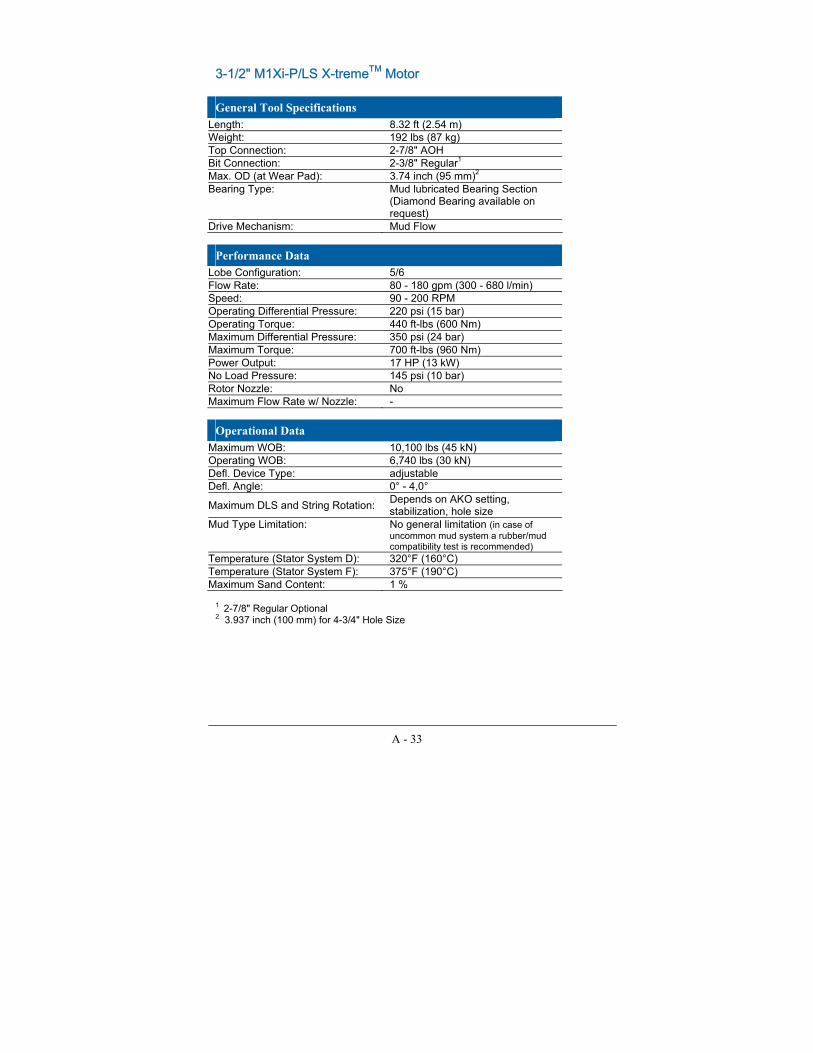
A - 33
3-1/2" M1Xi-P/LS X-tremeTM Motor General Tool Specifications
Length: 8.32 ft (2.54 m) Weight: 192 lbs (87 kg) Top Connection: 2-7/8" AOH Bit Connection: 2-3/8" Regular1 Max. OD (at Wear Pad): 3.74 inch (95 mm)2 Bearing Type: Mud lubricated Bearing Section
(Diamond Bearing available on request)
Drive Mechanism: Mud Flow
Performance Data Lobe Configuration: 5/6 Flow Rate: 80 - 180 gpm (300 - 680 l/min) Speed: 90 - 200 RPM Operating Differential Pressure: 220 psi (15 bar) Operating Torque: 440 ft-lbs (600 Nm) Maximum Differential Pressure: 350 psi (24 bar) Maximum Torque: 700 ft-lbs (960 Nm) Power Output: 17 HP (13 kW) No Load Pressure: 145 psi (10 bar) Rotor Nozzle: No Maximum Flow Rate w/ Nozzle: -
Operational Data Maximum WOB: 10,100 lbs (45 kN) Operating WOB: 6,740 lbs (30 kN) Defl. Device Type: adjustable Defl. Angle: 0° - 4,0°
Maximum DLS and String Rotation: Depends on AKO setting, stabilization, hole size
Mud Type Limitation: No general limitation (in case of uncommon mud system a rubber/mud compatibility test is recommended)
Temperature (Stator System D): 320°F (160°C) Temperature (Stator System F): 375°F (190°C) Maximum Sand Content: 1 %
1 2-7/8" Regular Optional 2 3.937 inch (100 mm) for 4-3/4" Hole Size

A - 34
3-1/2" M1X-P/LS X-tremeTM Motor General Tool Specifications
Length: 24.3 ft (7.39 m) Weight: 448 lbs (203 kg) Top Connection: 2-7/8" AOH Bit Connection: 2-3/8" Regular1 Max. OD (at Wear Pad): 3.74 inch (95 mm) Bearing Type: Mud lubricated Bearing Section
(Diamond Bearing available on request)
Drive Mechanism: Mud Flow
Performance Data Lobe Configuration: 5/6 Flow Rate: 80 - 180 gpm (300 - 680 l/min) Speed: 90 - 200 RPM Operating Differential Pressure: 580 psi (40 bar) Operating Torque: 1,165 ft-lbs (1,580 Nm) Maximum Differential Pressure: 725 psi (50 bar) Maximum Torque: 1,455 ft-lbs (1,975 Nm) Power Output: 44 HP (33 kW) No Load Pressure: 160 psi (11 bar) Rotor Nozzle: No Maximum Flow Rate w/ Nozzle: -
Operational Data Maximum WOB: 13,500 lbs (60 kN) Operating WOB: 8,990 lbs (40 kN) Defl. Device Type: adjustable Defl. Angle: 0° - 3,2°
Maximum DLS and String Rotation: Depends on AKO setting, stabilization, hole size
Mud Type Limitation: No general limitation (in case of uncommon mud system a rubber/mud compatibility test is recommended)
Temperature (Stator System D): 320°F (160°C) Temperature (Stator System F): 375°F (190°C) Maximum Sand Content: 1 %
1 2-7/8" Regular optional

A - 35
3-1/2" M2XL-P X-tremeTM Motor General Tool Specifications
Length: 23.92 ft (7.29 m) Weight: 593 lbs (269 kg) Top Connection: 2-7/8" AOH Bit Connection: 2-3/8" Regular1 Max. OD (at Wear Pad): 3.74 inch (95 mm) Bearing Type: Mud lubricated Bearing Section
(Diamond Bearing available on request)
Drive Mechanism: Mud Flow
Performance Data Lobe Configuration: 1/2 Flow Rate: 60 - 130 gpm (230 - 490 l/min) Speed: 400 - 890 RPM Operating Differential Pressure: 1,525 psi (105 bar) Operating Torque: 550 ft-lbs (745 Nm) Maximum Differential Pressure: 2,030 psi (140 bar) Maximum Torque: 735 ft-lbs (995 Nm) Power Output: 92 HP (69 kW) No Load Pressure: 290 psi (20 bar) Rotor Nozzle: No Maximum Flow Rate w/ Nozzle: -
Operational Data Maximum WOB: 13,500 lbs (60 kN) Operating WOB: 8,990 lbs (40 kN) Defl. Device Type: adjustable Defl. Angle: 0° - 3,2°
Maximum DLS and String Rotation: Depends on AKO setting, stabilization, hole size
Mud Type Limitation: No general limitation (in case of uncommon mud system a rubber/mud compatibility test is recommended)
Temperature (Stator System D): 320°F (160°C) Temperature (Stator System F): 375°F (190°C) Maximum Sand Content: 1 %
1 2-7/8" Regular optional
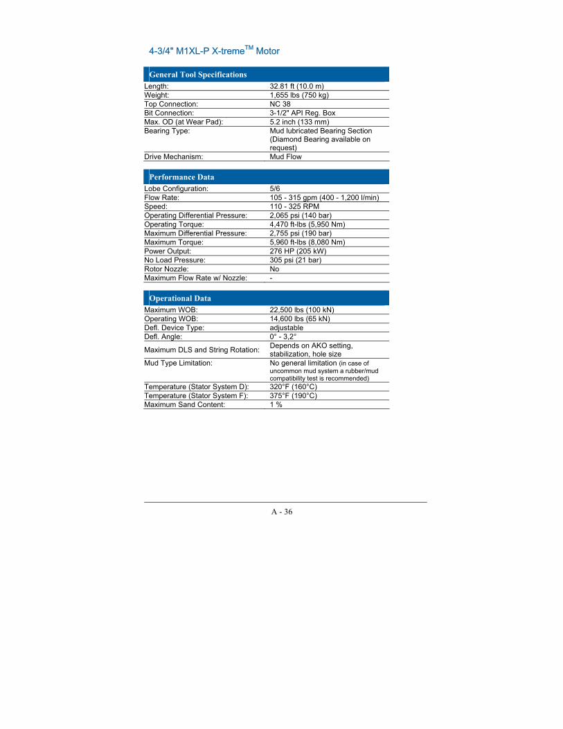
A - 36
4-3/4" M1XL-P X-tremeTM Motor General Tool Specifications
Length: 32.81 ft (10.0 m) Weight: 1,655 lbs (750 kg) Top Connection: NC 38 Bit Connection: 3-1/2" API Reg. Box Max. OD (at Wear Pad): 5.2 inch (133 mm) Bearing Type: Mud lubricated Bearing Section
(Diamond Bearing available on request)
Drive Mechanism: Mud Flow
Performance Data Lobe Configuration: 5/6 Flow Rate: 105 - 315 gpm (400 - 1,200 l/min) Speed: 110 - 325 RPM Operating Differential Pressure: 2,065 psi (140 bar) Operating Torque: 4,470 ft-lbs (5,950 Nm) Maximum Differential Pressure: 2,755 psi (190 bar) Maximum Torque: 5,960 ft-lbs (8,080 Nm) Power Output: 276 HP (205 kW) No Load Pressure: 305 psi (21 bar) Rotor Nozzle: No Maximum Flow Rate w/ Nozzle: -
Operational Data Maximum WOB: 22,500 lbs (100 kN) Operating WOB: 14,600 lbs (65 kN) Defl. Device Type: adjustable Defl. Angle: 0° - 3,2°
Maximum DLS and String Rotation: Depends on AKO setting, stabilization, hole size
Mud Type Limitation: No general limitation (in case of uncommon mud system a rubber/mud compatibility test is recommended)
Temperature (Stator System D): 320°F (160°C) Temperature (Stator System F): 375°F (190°C) Maximum Sand Content: 1 %

A - 37
4-3/4" M4XL X-tremeTM Motor General Tool Specifications
Length: 30.8 ft (9.4 m) Weight: 1,410 lbs (640 kg) Top Connection: NC 38 Bit Connection: 3-1/2" API Reg. Box Max. OD (at Wear Pad): 5.1 inch (130 mm)
Bearing Type: Mud lubricated Diamond Bearing Section
Drive Mechanism: Mud Flow
Performance Data Lobe Configuration: 1/2 Flow Rate: 130 - 315 gpm (500 - 1,200 l/min) Speed: 520 - 1,250 RPM Operating Differential Pressure: 1,520 psi (105 bar) Operating Torque: 960 ft-lbs (1,300 Nm) Maximum Differential Pressure: 2,436 psi (168 bar) Maximum Torque: 1,475 ft-lbs (2,000 Nm) Power Output: 230 HP (170 kW) No Load Pressure: 200 psi (14 bar) Rotor Nozzle: No Maximum Flow Rate w/ Nozzle: -
Operational Data Maximum WOB: 22,500 lbs (100 kN) Operating WOB: 14,600 lbs (65 kN) Defl. Device Type: adjustable Defl. Angle: 0° - 3,2°
Maximum DLS and String Rotation: Depends on AKO setting, stabilization, hole size
Mud Type Limitation: No general limitation (in case of uncommon mud system a rubber/mud compatibility test is recommended)
Temperature (Stator System D): 265°F (130°C) Temperature (Stator System F): 320°F (160°C) Maximum Sand Content: 1 %

A - 38
6-3/4" M1XL-P X-tremeTM Motor General Tool Specifications
Length: 35.4 ft (10.8 m) Weight: 2,980 lbs (1,350 kg) Top Connection: NC 50 Bit Connection: 4-1/2" API Reg. Box Max. OD (at Wear Pad): 7.3 inch (186 mm) Bearing Type: Mud lubricated Bearing Section
(Diamond Bearings available on request)
Drive Mechanism: Mud Flow
Performance Data Lobe Configuration: 5/6
Flow Rate: 265 - 660 gpm (1,000 - 2,500 l/min)
Speed: 90 - 220 RPM Operating Differential Pressure: 1,305 psi (90 bar) Operating Torque: 8,670 ft-lbs (11,760 Nm) Maximum Differential Pressure: 1,740 psi (120 bar) Maximum Torque: 11,560 ft-lbs (15,675 Nm) Power Output: 363 HP (270 kW) No Load Pressure: 348 psi (24 bar) Rotor Nozzle: No Maximum Flow Rate w/ Nozzle: -
Operational Data Maximum WOB: 54,000 lbs (240 kN) Operating WOB: 36,000 lbs (160 kN) Defl. Device Type: adjustable Defl. Angle: 0° - 2,75°
Maximum DLS and String Rotation: Depends on AKO setting, stabilization, hole size
Mud Type Limitation: No general limitation (in case of uncommon mud system a rubber/mud compatibility test is recommended)
Temperature (Stator System D): 320°F (160°C) Temperature (Stator System F): 375°F (190°C) Maximum Sand Content: 1 %

A - 39
6-3/4" M4XL-P X-tremeTM Motor General Tool Specifications
Length: 31.5 ft (9.6 m) Weight: 2,756 lbs (1,250 kg) Top Connection: NC 50 Bit Connection: 4-1/2" API Reg. Box Max. OD (at Wear Pad): 7.4 inch (188 mm) Bearing Type: Mud lubricated Bearing Section
(Diamond Bearing available on request)
Drive Mechanism: Mud Flow
Performance Data Lobe Configuration: 1/2
Flow Rate: 265 - 530 gpm (1,000 - 2,000 l/min)
Speed: 450 - 900 RPM Operating Differential Pressure: 1,960 psi (135 bar) Operating Torque: 2,880 ft-lbs (3,900 Nm) Maximum Differential Pressure: 2,610 psi (180 bar) Maximum Torque: 3,845 ft-lbs (5,210 Nm) Power Output: 493 HP (368 kW) No Load Pressure: 174 psi (12 bar) Rotor Nozzle: No Maximum Flow Rate w/ Nozzle: -
Operational Data Maximum WOB: 45,000 lbs (200 kN) Operating WOB: 30,300 lbs (135 kN) Defl. Device Type: adjustable Defl. Angle: 0° - 2,75°
Maximum DLS and String Rotation: Depends on AKO setting, stabilization, hole size
Mud Type Limitation: No general limitation (in case of uncommon mud system a rubber/mud compatibility test is recommended)
Temperature (Stator System D): 320°F (160°C) Temperature (Stator System F): 375°F (190°C) Maximum Sand Content: 1 %

A - 40
9-1/2" M1X-P X-tremeTM Motor General Tool Specifications
Length: 29.2 ft (8.9 m) Weight: 6,615 lbs (3,000 kg) Top Connection: 6-5/8" API Reg. Box (7 5/8" API
Reg.) Bit Connection: 6-5/8" API Reg. Box Max. OD (at Wear Pad): 10.6 inch (270 mm) Bearing Type: Mud lubricated Bearing Section Drive Mechanism: Mud Flow
Performance Data Lobe Configuration: 5/6
Flow Rate: 530 - 1,160 gpm (2,000 - 4,400 l/min)
Speed: 80 - 185 RPM Operating Differential Pressure: 1,160 psi (80 bar) Operating Torque: 16,450 ft-lbs (22,300 Nm) Maximum Differential Pressure: 1,450 psi (100 bar) Maximum Torque: 20,565 ft-lbs (27,900 Nm) Power Output: 575 HP (430 kW) No Load Pressure: 220 psi (15 bar) Rotor Nozzle: Yes Maximum Flow Rate w/ Nozzle: 1,160 gpm (4,400 l/min)
Operational Data Maximum WOB: 92,170 lbs (410 kN) Operating WOB: 60,700 lbs (270 kN) Defl. Device Type: adjustable Defl. Angle: 0° - 2,0°
Maximum DLS and String Rotation: Depends on AKO setting, stabilization, hole size
Mud Type Limitation: No general limitation (in case of uncommon mud system a rubber/mud compatibility test is recommended)
Temperature (Stator System D): 320°F (160°C) Temperature (Stator System F): 375°F (190°C) Maximum Sand Content: 1 %
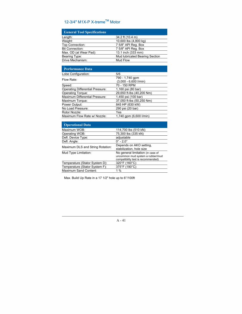
A - 41
12-3/4" M1X-P X-tremeTM Motor General Tool Specifications
Length: 34.2 ft (10.4 m) Weight: 10,600 lbs (4,800 kg) Top Connection: 7 5/8" API Reg. Box Bit Connection: 7 5/8" API Reg. Box Max. OD (at Wear Pad): 13.1 inch (333 mm) Bearing Type: Mud lubricated Bearing Section Drive Mechanism: Mud Flow
Performance Data Lobe Configuration: 5/6
Flow Rate: 790 - 1,740 gpm (3,000 - 6,600 l/min)
Speed: 70 - 150 RPM Operating Differential Pressure: 1,160 psi (80 bar) Operating Torque: 29,650 ft-lbs (40,200 Nm) Maximum Differential Pressure: 1,450 psi (100 bar) Maximum Torque: 37,050 ft-lbs (50,250 Nm) Power Output: 845 HP (630 kW) No Load Pressure: 290 psi (20 bar) Rotor Nozzle: Yes Maximum Flow Rate w/ Nozzle: 1,740 gpm (6,600 l/min)
Operational Data Maximum WOB: 114,700 lbs (510 kN) Operating WOB: 75,300 lbs (335 kN) Defl. Device Type: adjustable Defl. Angle: 0° - 2,0°
Maximum DLS and String Rotation: Depends on AKO setting, stabilization, hole size
Mud Type Limitation: No general limitation (in case of uncommon mud system a rubber/mud compatibility test is recommended)
Temperature (Stator System D): 320°F (160°C) Temperature (Stator System F): 375°F (190°C) Maximum Sand Content: 1 %
Max. Build Up Rate in a 17 1/2" hole up to 6°/100ft

B - 1
Appendix B
APPENDIX B: Nozzle Size Charts
SI Units

US Units
B - 2

C - 1
Appendix C
APPENDIXC: Abbreviations
AKO Adjustable Kick Off Sub API American Petroleum Institute BHA Bottomhole Assembly BUR Build Up Rate CSNMDP Compressive Service Non Magnetic Drill Pipe DLS Dog Leg Severity ECD Equivalent Circulating Density HP/HT High Pressure/High Temperature LCM Lost Circulation Material LGS Low Gravity Solids LWD Logging While Drilling MWD Measurement While Drilling OBM Oil-based Fluids PDC Polycrystalline Diamond Compact POOH Pulling Out Of Hole ROP Rate of Penetration RPM Revolution Per Minute RWD Ream While Drilling SBM Synthetic-based Fluids SWRD Steerable Ream While Drilling TOB Torque On Bit TSP Thermally Stable PDC bit WBM Water-based Fluids WOB Weight On Bit