National Center for Hypersonic Combined Cycle Propulsion Williamsburg, Virginia, June 16, 2011

National Center for Hypersonic Combined Cycle Propulsion
Professor Jim McDanielPrincipal InvestigatorUniversity of Virginia
AFOSR-NASA Hypersonics Research ReviewWilliamsburg, VA
June 16, 2011

National Center for Hypersonic Combined Cycle Propulsion
Review Meeting Agenda
2
8:15 – 8:45 Center Overview: Jim McDaniel, University of Virginia8:45 – 9:15 Turbine/Ramjet Mode Transition: Kevin Bowcutt, Boeing 9:15 – 9:45 Ramjet/Scramjet Mode Transition (experimental): Chris Goyne, University of Virginia
9:45 – 10:00 BREAK
10:00 – 10:30 Ramjet/Scramjet Mode Transition (computational): Jack Edwards, North Carolina State University
10:30 – 11:00 Tunable Diode Laser Absorption Spectroscopy: Ron Hanson, Stanford University11:00 – 11:30 Coherent Antistokes Raman Spectroscopy: Andrew Cutler, George Washington
University11:30 – 12:00 Hypervelocity Regime: Dan Cresci, ATK/GASL
12:00 ‐ 1:15 LUNCH
1:15 ‐ 1:45 Advanced Modeling: Farhad Jaberi, Michigan State University1:45 ‐ 2:15 Chemistry Modeling: Steve Pope, Cornell University2:15 ‐ 2:45 Closing Remarks: Jim McDaniel, University of Virginia
END OF REVIEW MEETING
2:45 ‐ 3:15 BREAK3:15 ‐ 4:00 Advisory Board Meeting (Center participants and board
members only)
Note: The last 5 minutes of each presentation will be reserved for Q/A

National Center for Hypersonic Combined Cycle Propulsion
3
Overview of Center

National Center for Hypersonic Combined Cycle Propulsion
4
Center Overview
1. Introduction- Center Technical Roadmap- Objectives- Research Approach- Center Organization
2. Fundamental Modeling and Experimental Synergy
3. Examples of Year 2 Research

National Center for Hypersonic Combined Cycle Propulsion
5
Turbine-Based Combined Cycle Concept

National Center for Hypersonic Combined Cycle Propulsion
6
National Center for Hypersonic Combined Cycle Propulsion
7
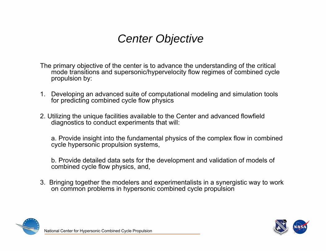
Center Objective
The primary objective of the center is to advance the understanding of the critical mode transitions and supersonic/hypervelocity flow regimes of combined cycle propulsion by:
1. Developing an advanced suite of computational modeling and simulation tools for predicting combined cycle flow physics
2. Utilizing the unique facilities available to the Center and advanced flowfield diagnostics to conduct experiments that will:
a. Provide insight into the fundamental physics of the complex flow in combined cycle hypersonic propulsion systems,
b. Provide detailed data sets for the development and validation of models of combined cycle flow physics, and,
3. Bringing together the modelers and experimentalists in a synergistic way to work on common problems in hypersonic combined cycle propulsion

National Center for Hypersonic Combined Cycle Propulsion
Research Approach
1. Develop and implement a hierarchy of novel methodologies for high fidelity simulations of various flow paths. These methodologies range from:
a. Current production-level Generation I RANS simulations, tob. New Generation II hybrid LES/RANS and LES/S-FMDF methods, toc. The most sophisticated envisioned form of LES/EPVS-FMDF for Generation III prediction of
hypervelocity reacting flows, and d. Detailed/reduced kinetics models for thermal decomposition/oxidation of relevant hydrocarbon
fuels.
2. Conduct experiments that will:
a. Elucidate the fundamental flow physics of compressible, turbulent reacting flows in combined cycle systems,
b. Measure reacting flow turbulent statistics and novel fuel-air mixing and flameholding approaches through the development and application of advanced diagnostics,
c. Develop benchmark data sets with quantified experimental uncertainty for the purposes of developing accurate Generation I, II and III models.
National Center for Hypersonic Combined Cycle Propulsion
9
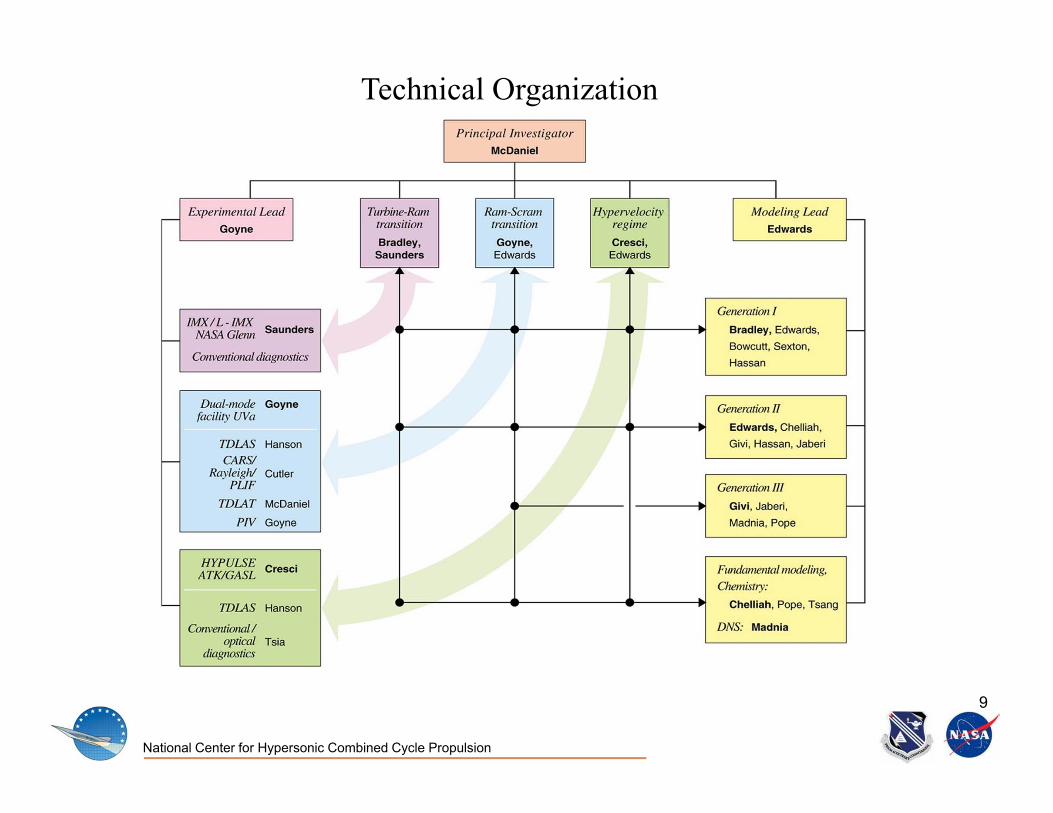
Technical Organization

National Center for Hypersonic Combined Cycle Propulsion
10
Fundamental Modelingand
Experimental Synergy

National Center for Hypersonic Combined Cycle Propulsion
Experimental Capabilities and Modeling Quantities DerivedMeasurementTechnique
Measured Quantities Modeling Quantities Derived
CARS N2, O2, H2, CO2, CO mole fractions and temperature, single point, instantaneous
Scatter plots of temperature and species versus mixture fraction, overall heat release, averaged and rms values of temperature and species.
SPIV Three velocity components, planar, instantaneous
Planar filtered velocity, subgrid scale stress and dissipation, multiplecomponent correlations, filtered energy components, velocity gradients, strain rates, vorticity,
TDLAS H2O, O2, CO2, CO, H-C and temperature, line-of-sight, kHz acquisitionrates
Comparison to line-integrated LES and DNS data for model validation
TDLAT H2O, CO2 and temperature, planar, time averaged
Correlation of time averages species and temperature for global assessment of RANS or LES models
PLIF OH and NO, planar, instantaneous, semi-quantitative
Location of shocks and flame boundaries for validation of spatial RANS and LES solutions
Rayleigh 2 velocity components and density, single point, instantaneous
Favre and non-Favre averaged velocity, averaged density

National Center for Hypersonic Combined Cycle Propulsion
12
FLOW PROBLEM PROGRESSION PHYSICAL PHENOMENA MODELING APPROACH DATA NEEDED
Unbounded flowsTemporally Developing Mixing Layer Compressible Inhomogeneous
TurbulenceLES/FMDF DNS
Isotropic turbulence with normal shock 3‐D vortical structure interactions with shock
LES/FMDF DNS
Turbulent mixing layer with oblique shock
3‐D vortical structure interactions with shock
LES/FMDF DNS
Supersonic nonreacting & reacting mixing layer and jet
Compressible Turbulence and Combustion
LES/FMDF GWU Co‐Annular Jet, DNS
Wall‐bounded flows (non‐reacting)
Flow in constant area duct SBLI, corner vortices RANS, HYBRID LES‐RANS UVa isolator PIV
Flow in constant area duct with ramp injection
SBLI, shock‐vortex interactions RANS, LES‐RANS, LES/FMDF UVa non‐reacting combustor PIV
Flow in constant area duct, ramp injection, dual‐mode
SBLI, shock‐vortex interactions RANS, LES‐RANS, LES/FMDF UVa nonreacting combustor and isolator PIV
Wall‐bounded flows (reacting)
Flow in constant area duct with ramp injection and low Ф hydrogen
combustionwithout isolator
ignition, flameholding, shock‐turbulence‐combustion interactions
RANS, LES‐RANS, LES/FMDF UVa combustor, PIV, CARS, TDLAS, TDLAT
Flow in constant area duct with ramp Injection and high Ф hydrogen
combustion, dual‐mode, with isolator
Ignition, flameholding, shock‐turbulence‐combustion interactions, effects of
isolator
RANS, LES‐RANS, LES/FMDF UVa combustor and isolator PIV, CARS, TDLAS, TDLAT
Same as last two cases with ethylene combustion
Same RANS, LES‐RANS, LES/FMDF + reduced kinetics
UVa combustor and isolator, PIV, CARS, TDLAS, TDLAT
Complex flowsNASA Glenn IMX SBLI, 3D flow separation, boundary layer
bleed RANS, HYBRID LES/RANS wall pressure, pitot surveys
HYPULSE Same as UVA experiments plus transient and non‐equilibrium effects
RANS, HYBRID LES/RANS ATK/GASL TDLAS, wall pressure & heat flux, fuel
plume imaging
Fundamental Modeling Problems and Validation Data Needed

National Center for Hypersonic Combined Cycle Propulsion
Isolator Combustor Extender
LES of SBLI in Isolator(Dual-Mode)
LES/RANS and LES/S-FMDF (Gen. II) Simulations of UVa Dual-Mode Combustor
Isolator Combustor TDLAT Section Extender
LES/RANS (top) and RANS (bottom) of Temperature in Reacting Combustor (supersonic mode, Ф = 0.34)

National Center for Hypersonic Combined Cycle Propulsion
Simple Fuel Jet in Supersonic Cross Flow
Jet Mixing and Backstep Stabilizer Jet Mixing and Cavity Stabilizer
LES Grid LES Grid LES Grid
Sonic Fuel Jet Sonic Fuel Jet Sonic Fuel Jet
LES/FMDF of Fuel-Air Mixing with Various UVa Injection Geometries

National Center for Hypersonic Combined Cycle Propulsion
15
Measurement Locations and Measurement Techniques
1
2 SPIV, CARS, Rayleigh, TDLAS, PLIF
3
4
3
5
1 222 544 4 4111 1
SPIV, CARS, Rayleigh, TDLAS
3 3
SPIV, CARS, Rayleigh, TDLAS, PLIF, TDLAT, combustion efficiency
CARS, TDLAS
SPIV, CARS, Rayleigh, TDLAS, PLIF, TDLAT, combustion efficiency

National Center for Hypersonic Combined Cycle Propulsion
Tunnel Control Room
Tunnel Setup Area
Tunnel Room TDLAT/GWU Lab
PIV/TDLAS Lab
CARS/IRS/PLIF
TDLAS
SPIV
SPIV
TDLATUVa
GWU
UVa
UVa
Stanford
Experimental Collaboration:UVa Dual-Mode Combustion Facility
UVa Dual-Mode Combustion Tunnel Optical table

National Center for Hypersonic Combined Cycle Propulsion
17
Examples of Year 2 Research

National Center for Hypersonic Combined Cycle Propulsion
Immersed Boundary Methodology: simulating bleed flow through individual bleed holes in bleed
surfaces from CAD file definition
Dual-inlet Mode TransitionGeneration II IMX CFD Results
CAD file rendition of IMX bleed region
Supersonic flow
High-speed flowpath
Low-speedflowpath
Bleed reserviors
Mach number

National Center for Hypersonic Combined Cycle Propulsion
19
New Dual-Mode Combustion Facility

National Center for Hypersonic Combined Cycle Propulsion
20
SPIV Results at X/H = 10, = 0.25
Fuel-air Mixing
Fuel-air Combustion

National Center for Hypersonic Combined Cycle Propulsion
21
Flame structure using RANS• 2.9 deg. divergent-
wall combustor• Ф = 0.4
Mach number (centerplane)
Temperature contoursOH contours

National Center for Hypersonic Combined Cycle Propulsion
22
Hypervelocity Regime: HYPULSE at ATK/GASL
Supersonic Air Exhaust
Optical Fibers
5 Beam PathsH2 Fuel Injector Ramp
L~1”

National Center for Hypersonic Combined Cycle Propulsion
Incident shock β = 30o
Pressure
TemperatureNormal Shock Wave
Oblique Shock Wave Supersonic Turbulent Mixing Layer
with Combustion
Spatially-Developing Mixing Layer with Shock
Shock-Isotropic Turbulence Interaction Shock-Turbulent BL Interaction
Advanced Modeling: DNS of High-Speed Turbulent Flows (Generation III)
H2 + Air
Air
Inviscid Wall
Supported by AFRL

National Center for Hypersonic Combined Cycle Propulsion
Chemistry Modeling: Detailed and Simplified Kinetic Models• Rate parameters of detailed kinetic models are associated with large
uncertainty factors, which lead to large variation in flame extinction limits, eg. extinction strain rates from 800 to 1600 s-1
• Global sensitivity analysis can yield valuable information about first-order effects and second-order effects of rate parameters
24
• Comprehensive model reduction strategies developed have included ignition, propagation, and extinction limits and has been accomplished via PCA and QSSA
- Starting from a detailed ethylene-air kinetic model containing 111 species in 784 reversible reactions, skeletal model with 37-38 species and reduced reaction model with 20-24 species have been developed
• Develop computational efficient strategies of implementing reduced order models (i.e. skeletal, reduced, RCCE) using ISAT methodology.
• Implementation in Partially-Stirred Reactor simulations have shown a reduction of 1000 times over direct evaluation of the detailed model.

National Center for Hypersonic Combined Cycle Propulsion
25
Questions ?