Nais Plc Fp2
39
Panasonic Programmable Controller FP2 CTi Automation - Phone: 800.894.0412 - Fax: 208.368.0415 - Web: www.ctiautomation.net - Email: [email protected]
-
Upload
hieutran86 -
Category
Documents
-
view
44 -
download
1
description
Panasonic PLC Nais FP2
Transcript of Nais Plc Fp2

Panasonic
Programmable Controller FP2
CTi Automation - Phone: 800.894.0412 - Fax: 208.368.0415 - Web: www.ctiautomation.net - Email: [email protected]
2
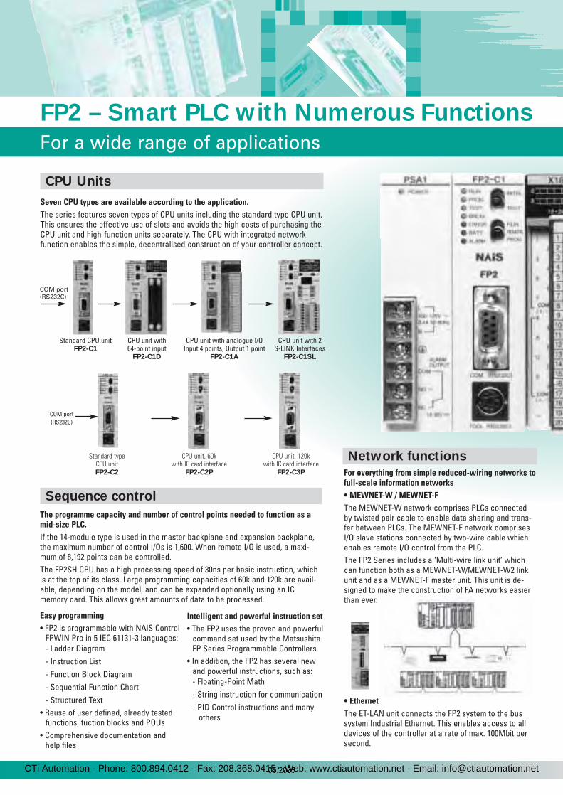
Seven CPU types are available according to the application.The series features seven types of CPU units including the standard type CPU unit.This ensures the effective use of slots and avoids the high costs of purchasing theCPU unit and high-function units separately. The CPU with integrated networkfunction enables the simple, decentralised construction of your controller concept.
FP2 – Smart PLC with Numerous Functions
For a wide range of applications
CPU Units
Sequence control
Network functions
Standard CPU unitFP2-C1
CPU unit with64-point input
FP2-C1D
CPU unit with analogue I/OInput 4 points, Output 1 point
FP2-C1A
CPU unit with 2S-LINK Interfaces
FP2-C1SL
Standard typeCPU unitFP2-C2
CPU unit, 60kwith IC card interface
FP2-C2P
CPU unit, 120kwith IC card interface
FP2-C3P
The programme capacity and number of control points needed to function as amid-size PLC.If the 14-module type is used in the master backplane and expansion backplane,the maximum number of control I/Os is 1,600. When remote I/O is used, a maxi-mum of 8,192 points can be controlled.The FP2SH CPU has a high processing speed of 30ns per basic instruction, whichis at the top of its class. Large programming capacities of 60k and 120k are avail-able, depending on the model, and can be expanded optionally using an ICmemory card. This allows great amounts of data to be processed.
Easy programming• FP2 is programmable with NAiS Control
FPWIN Pro in 5 IEC 61131-3 languages:- Ladder Diagram- Instruction List- Function Block Diagram- Sequential Function Chart- Structured Text
• Reuse of user defined, already testedfunctions, fuction blocks and POUs
• Comprehensive documentation andhelp files
Intelligent and powerful instruction set• The FP2 uses the proven and powerful
command set used by the MatsushitaFP Series Programmable Controllers.
• In addition, the FP2 has several newand powerful instructions, such as:- Floating-Point Math- String instruction for communication- PID Control instructions and many
others
For everything from simple reduced-wiring networks tofull-scale information networks• MEWNET-W / MEWNET-FThe MEWNET-W network comprises PLCs connectedby twisted pair cable to enable data sharing and trans-fer between PLCs. The MEWNET-F network comprisesI/O slave stations connected by two-wire cable whichenables remote I/O control from the PLC.The FP2 Series includes a ‘Multi-wire link unit’ whichcan function both as a MEWNET-W/MEWNET-W2 linkunit and as a MEWNET-F master unit. This unit is de-signed to make the construction of FA networks easierthan ever.
• EthernetThe ET-LAN unit connects the FP2 system to the bussystem Industrial Ethernet. This enables access to alldevices of the controller at a rate of max. 100Mbit persecond.
COM port (RS232C)
COM port(RS232C)
CTi Automation - Phone: 800.894.0412 - Fax: 208.368.0415 - Web: www.ctiautomation.net - Email: [email protected]

• PROFIBUS FMS/DPPROFIBUS FMS/DP master unitsenable open communication inter-faces.
• S-LINKS-LINK replaces the loom of cables by dealing with thesignal at its source. Each I/O module is connected to aflat cable with four leads. The T structure of the net-work is especially suited for machines and assembly lines, but also for internal building systems, e.g. firealarms, lighting. The FP2 CPU with integrated S-LINKinterface has two terminal ports, the S-LINK communi-cation module has one port. Up to 128 I/Os can beconnected per network branch.
Offering high-resolution positioning at low cost.The FP2 Series positioning unit has a maxi-mum pulse output of 4Mpps and starts at ahigh speed of 0.005msec - from reception ofthe positioning command from the CPU togeneration of the pulse. This helps to achievelow-cost tact-time reduction and true positio-ning control. The FP2-PP4 positioning unitscan control 4 axes in one unit.
Positioning control
With range switching, the system can handle all types of analogue equipment.A thermocouple or resistance thermometer bulb can also be directly connected.The FP2 Series includes analogue input and output units and a CPU unit equippedwith an analogue I/O port comprising four range-swichable inputs and one output.The system is therefore able to handle all types of analogue control.
Analogue control
*Compatible with pulse input drives.
Motordriver
Stepping motorServo motor
RUNPOWERPROGTESTBREAKERRORBATTALARM
L
N
100-120V~0.4A 50-60Hz
COM
ALARMOUTPUT
NO—
NC
RUNREMOTEPROG
TEST
S-LINK
TOOL(RS232C)
COM.(RS232C)
1
INITIAL
PS1A FP2-C1SL
CN2CN1
CN2CN1 CN2CN1
0 7F171F
81018
24V
X64D2
CN2CN1
0 7F171F
81018
Tr.(PNP)0.1A5-24V
Y64P
CN2CN1
CN2CN1
0 7F171F
81018
Tr.(PNP)0.1A5-24V
Y64P
The CPU with an S-LINK is equipped with two ports.The S-LINK unit is equipped with one port.
Up to 128 points per port
Maximum length: 200m
Up to 128 points per port
RUNPOWERPROGTESTBREAKERRORBATTALARM
L
N
100-120V~0.4A 50-60Hz
COM
ALARMOUTPUT
NO
NC
RUNREMOTEPROG
TEST
S-LINK
RUN CHK.
ADDRESS
COM.(RS232C)
MONITOR
MODE
1 2
INITIAL
PS1A FP2-C1SL
CN2CN1
1234
56789ABCDEF012
34
56789ABCDEF0
1234
56789ABCDEF012
34
56789ABCDEF0
B
24V0V
D
G
24V0V
24V
0V
D
G
A
IN
B
A
IN
1 3 4
04
37
S-LINK1
SD ERROR1 3 4
04
37
S-LINK2
SD ERROR
CN2CN1
0 7F171F
81018
Tr.(PNP)0.1A5-24V
Y64P
RUN CHK.
ADDRESS
MONITOR
MODE
SET
1234
56789ABCDEF012
34
56789ABCDEF0
B
24V0V
D
G
24V0V
24V
0V
D
G
IN
A
SEND0 7
ERROR
1 3 4SL2
TOOL(RS232C) S-LINK2S-LINK1
CPU unit features an RS232C port as standard.All CPU units in the FP2 Series have an RS232C port as standard. This allows adirect link to be created with a personal computer or an operation display panel.If a modem is connected, the interface can also be used for data transmission toremote locations and program amendment and upgrading. If the C-NET unit is con-nected to the RS232C port, data can easily be exchanged between various PLCs.
Communication functions
3
OUTPUT
+5V
0-10W
shitaPMS Ltd
ON
OFF
SPEED
1KHz100Hz10Hz
GAIN
HIGHARTLOW
ANAROGLM100
ZEARD ART
+–
RANGE
LANG EM15M
BRIGHT
DARK
LASERSENSOR
PanasonicAC SERVO DRIVERDV40P 005LD2A
AC100V
UP
DN
SEL
BASPMIM
GND
CN2I/F
PG
CN1SIG
R
T
r
t
U
V
W
E
M
SUHX DPX-200A
cmHg
Laser analoguesensor
Pressure sensor
Inverter
Analogue inputservo driver
Servo motor
• Hook up directly to an operation displaypanel or computer
RUNPOWERPROGTESTBREAKERRORBATTALARM
L
N
100-120V~0.4A 50-60Hz
COM
ALARM
OUTPUT
NO
NC
RUNREMOTEPROG
TEST
S-LINK
TOOL(RS232C)
COM.(RS232C)
1
INITIAL
PS1A FP2-C1SL
CN2CN1
CN2CN1 CN2CN1
0 7F171F
81018
24V
X64D2
CN2CN1
0 7F171F
81018
Tr.(PNP)0.1A5-24V
Y64P
CN2CN1
CN2CN1
0 7F171F
81018
Tr.(PNP)0.1A5-24V
Y64P
Host computer(commercially available)
Operation display panel(HMI)RS232C port
• Data transmission to PLC atremote location via modem
RUNPOWERPROGTESTBREAKERRORBATTALARM
L
N
100-120V~0.4A 50-60Hz
COM
ALARMOUTPUT
NO—
NC
RUNREMOTEPROG
TEST
S-LINK
TOOL(RS232C)
COM.(RS232C)
1
INITIAL
PS1A FP2-C1SL
CN2CN1
CN2CN1 CN2CN1
0 7F171F
81018
24V
X64D2
CN2CN1
0 7F171F
81018
Tr.(PNP)0.1A5-24V
Y64P
CN2CN1
CN2CN1
0 7F171F
81018
Tr.(PNP)0.1A5-24V
Y64P
Standard cross cablePart No. AFB85843 or equivalent
Standardstraight cable
FP Modem-EU FP Modem-EU
Telephone line
• PCWAY permits easy informationcollection
Data can be easily collected in the PLCusing the “PCWAY” Excel add-in utility. Inaddition to direct connections with a com-puter and PLC, “PCWAY” can also abtaininformation from networked PLCs or viamodem.
CTi Automation - Phone: 800.894.0412 - Fax: 208.368.0415 - Web: www.ctiautomation.net - Email: [email protected]
4
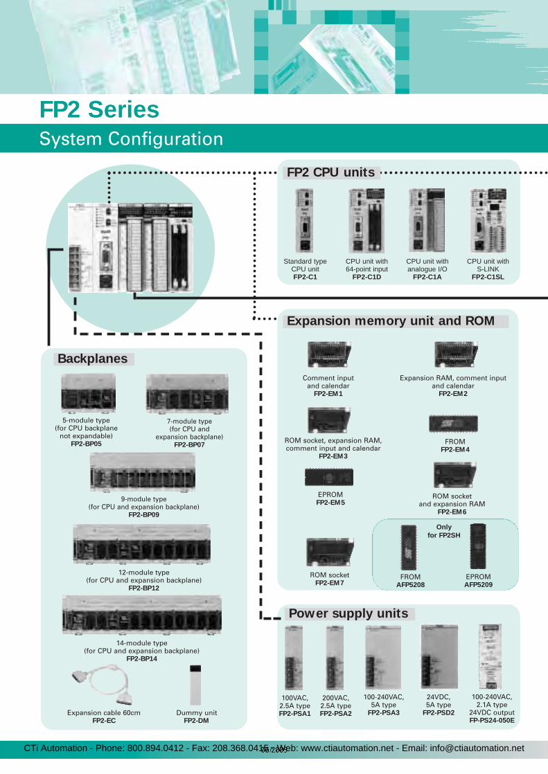
FP2 Series
System Configuration
Expansion memory unit and ROM
Backplanes
Power supply units
Standard typeCPU unitFP2-C1
CPU unit with64-point input
FP2-C1D
5-module type(for CPU backplane
not expandable)FP2-BP05
7-module type(for CPU and
expansion backplane)FP2-BP07
9-module type(for CPU and expansion backplane)
FP2-BP09
12-module type(for CPU and expansion backplane)
FP2-BP12
14-module type(for CPU and expansion backplane)
FP2-BP14
CPU unit withanalogue I/O
FP2-C1A
100VAC, 2.5A typeFP2-PSA1
200VAC, 2.5A typeFP2-PSA2
100-240VAC, 5A type
FP2-PSA3
24VDC, 5A type
FP2-PSD2
CPU unit withS-LINK
FP2-C1SL
Expansion cable 60cmFP2-EC
Dummy unitFP2-DM
Comment inputand calendar
FP2-EM1
Expansion RAM, comment inputand calendar
FP2-EM2
ROM socket, expansion RAM,comment input and calendar
FP2-EM3
FROMFP2-EM4
ROM socketFP2-EM7
EPROMFP2-EM5
ROM socketand expansion RAM
FP2-EM6
FP2 CPU units
FROMAFP5208
EPROMAFP5209
Only
for FP2SH
100-240VAC, 2.1A type
24VDC outputFP-PS24-050E
CTi Automation - Phone: 800.894.0412 - Fax: 208.368.0415 - Web: www.ctiautomation.net - Email: [email protected]

I/O units
16-point DC inputFP2-X16D2
16-point transistor
output (NPN)FP2-Y16T
32-point transistor
output (NPN)FP2-Y32T
64-point transistor
output (NPN)FP2-Y64T
16-point transistor
output (PNP)FP2-Y16P
32-point transistor
output (PNP)FP2-Y32P
64-point transistor
output (PNP)FP2-Y64P
6-point relay output
FP2-Y6R
16-point relay output
FP2-Y16R
64-point 32 input /32 input
(NPN)FP2-XY64D2T
64-point 32 input /32 input
(PNP)FP2-XY64D2P
64-point 32 input /32 output (NPN)with ON pulse catch input
FP2-XY64D7T
64-point 32 input /32 output (PNP)with ON pulse catch input
FP2-XY64D7P
32-point DC inputFP2-X32D2
64-point DC inputFP2-X64D2
Input unit
Output unit
I/O mixed unit
Analogue input unitFP2-AD8
Analogue output unit
FP2-DA4
Analogue I/O
FMS/DP-MasterPROFIBUS unitFP2-FMS/DP-M
DP-Master PROFIBUS unit
FP2-DP-M
ET-LAN unit
FP2-ET1
Multi-wire link unitFP2-MW
S-LINK unit
FP2-SL2
Serial data unit
FP2-SDU
ComputerCommunication unit
FP2-CCU
Positioning unittransistor output (2-axis)
FP2-PP21
Positioning unittransistor output (4-axis)
FP2-PP41
High SpeedCounter unit
FP2-HSCT
Positioning and counting units
Communication and networking units
FP2SH CPU units
FP2SH 60kFP2-C2
FP2SH 60kFP2-C2P
Positioning unitline driver output (2-axis)
FP2-PP22
Positioning unitline driver output (4-axis)
FP2-PP42
5
FP2 SeriesSystem Configuration
FP2SH 120kFP2-C3P
with IC cardinterface!
Pulse I/O unit
FP2-PXYT
CTi Automation - Phone: 800.894.0412 - Fax: 208.368.0415 - Web: www.ctiautomation.net - Email: [email protected]

6
FP2 Series
Unit Combination and Limitation
Type
Consider the combination of units so as not to exceed the rated capacity.
use the NAiS FP Power Supply (FPPS24050E) or an other commercially available power supply.
1,130 1,024
100-240VAC 5A type power supply unit24VAC 5A type power supply unit
CPU unit with 64-point inputCPU unit with analogue I/O
CPU unit with S-LINK (master)
FP2-PSA3FP2-PSD2FP2-C1D
FP2-C1A
FP2-C1SL
All backplanes except for the 5-module type can be used forexpansion.
Unit combination
Expansion of Backplane
Limitations on current consumption
CTi Automation - Phone: 800.894.0412 - Fax: 208.368.0415 - Web: www.ctiautomation.net - Email: [email protected]

Notes:
• The input unit displays the current flowing to the internal circuit. The other units display the current value required to drive the internal circuit. This value does not include the load current of the output unit.
• Refer to the manual of the positioning unit you are using to confirm the current consumed at 24V unit.
Type Order number Current consumption at 5VDC (mA)
Current consumption at 24VDC (mA)
FP2 CPU unit (same with expansion memory unit installed)ry
FP2-C1 410 or less
—FP2-C1D 530 or lessFP2-C1A 1,100 or lessFP2-C1SL 630 or less
Backplane
FP2-BP05 5 or less
—FP2-BP07 60 or lessFP2-BP09 60 or lessFP2-BP12 60 or lessFP2-BP14 60 or less
Input unit DC input16-point terminal type, 12 to 24VDC FP2-X16D2 60 or less 8 or less/point32-point connector type, 24VDC FP2-X32D2 80 or less 4.3 or less/point64-point connector type, 24VDC FP2-X64D2 100 or less 4.3 or less/point
Output unit
Relay output 6-point terminal type FP2-Y6R 50 or less 70 or less16-point terminal type FP2-Y16R 120 or less 160 or less
Transistor output
16-point terminal, NPN type FP2-Y16T 100 or less 120 or less32-point connector, NPN type FP2-Y32T 130 or less 120 or less64-point connector, NPN type FP2-Y64T 210 or less 250 or less16-point terminal, PNP type FP2-Y16P 80 or less 70 or less32-point connector, PNP type FP2-Y32P 130 or less 130 or less64-point connector, PNP type FP2-Y64P 210 or less 270 or less
I/O mixed unit
32-point 24VDC input/32-point connector, NPN output type
FP2-XY64D2T, FP2-XY64D7T 160 or less Input: 4.3 or less/point
Output: 120 or less32-point 24VDC input/32-point connector, PNP output type
FP2-XY64D2P, FP2-XY64D7P 160 or less Input: 4.3 or less/point
Output: 130 or less
Intelligent unit
Positioning unit
2-axis type, transistor output FP2-PP21 200 or less
(*Note)2-axis type, line driver output FP2-PP22 200 or less
Pulse I/O unit, NPN and PNP type FP2-PXYT 500 or less 200mAHigh-speed counter unit, NPN and PNP type FP2-HSCT 450 or less 200mAAnalogue input unit FP2-AD8 500 or less —Analogue output unit FP2-DA4 600 or less —PROFIBUS unit (FMS/DP-Master) FP2-FMS/DP-M 500 or less —PROFIBUS unit (DP-Master) FP2-DP-M 500 or less —ET-LAN unit FP2-ET1 670 or less —Multi-wire link unit FP2-MW 220 or less —S-LINK unit FP2-SL2 130 or less —Computer communication unit FP2-CCU 60 or less —Serial data unit FP2-SDU 60 or less —
FP2-C2FP2-C2P
FP2-C3P
750 or less
750 or less 750 or less
—FP2SH CPU units (same with expansion memory unit installed)
4-axis type, transistor output4-axis type, line driver output
FP2-PP41FP2-PP42
350 or less 350 or less
FP2 Series
Current Consumption
7
Table of current consumption at 5VDC/24VDC
5VDC is supplied by the FP2 power supply unit (FP2-PSA1, FP2-PSA2, FP2-PSA3 or FP2-PSD2).24VDC is supplied by the separate FP power supply FP-PS24-050E.
CTi Automation - Phone: 800.894.0412 - Fax: 208.368.0415 - Web: www.ctiautomation.net - Email: [email protected]

8
COM. port (RS232C) provided as standard equipment• Hook up directly to an operation display panel or computer.
• Using the 'PCWAY' movement data storage software programme enables data to be incorporated easily into Excel, without requiring any programming.
• Remote monitoring using a modem connection.
Communication port supports communication at 115.2KbpsBoth the TOOL port (RS232C) and the COM port (RS232C) provided as a standard feature support communication at 115.2Kbps. This enables high-speed communication when transferring programmes and when connected to external devices.
Ample programme capacityIn addition to an ample programme capacity of 16k steps for normal use, expansion memory can be used to extend the programme capacity to 32k steps.
Full line-up of advanced CPU units enable CPUs to be selected based on the application.Advanced packaging is available for individual applications, enabling a highly customized system architecture at a low price.
RUNPOWERPROGTESTBREAKERRORBATTALARM
L
N
100-120V~0.4A 50-60Hz
COM
ALARMOUTPUT
NO—
NC
RUNREMOTEPROG
TEST
S-LINK
TOOL(RS232C)
COM.(RS232C)
1
INITIAL
PS1A FP2-C1SL
CN2CN1
CN2CN1 CN2CN1
0 7F171F
81018
24V
X64D2
CN2CN1
F171F
81018
Tr.(PNP)0.1A5-24V
Y64P
CN2CN1
CN2CN1
0 7F171F
81018
Tr.(PNP)0.1A5-24V
Y64P
Host computer(commercially available)
Operation display panel(HMI)
COM. port(RS232C)
RUNPOWERPROGTESTBREAKERRORBATTALARM
L
N
100-120V~0.4A 50-60Hz
COM
ALARMOUTPUT
NO—
NC
RUNREMOTEPROG
TEST
S-LINK
TOOL(RS232C)
COM.(RS232C)
1
INITIAL
PS1A FP2-C1SL
CN2CN1
CN2CN1 CN2CN1
0 7F171F
81018
24V
X64D2
CN2CN1
F171F
81018
Tr.(PNP)0.1A5-24V
Y64P
CN2CN1
CN2CN1
0 7F171F
81018
Tr.(PNP)0.1A5-24V
Y64P
Standard cross cableStandard
straight cable
FP Modem-EU
Telephone line
Item Description
Controllable I/O points
basic construction max. 768 points (12 modules)expanded construction max. 1,600 points (25 modules)
using remote I/O system
max. 2,048 points (using MEWNET-F or S-LINK),max. 5,000 process data and I/O points (using PROFIBUS)
Operation speed (typical value)
basic instructions from 0.35µs per instructionhigh-level instructions from 0.93µs per instruction
Internal memory S-RAM
Programme capacity
internal memory approx. 16k steps using expansion memory approx. 32k steps
Operation memory
internal relays (R) 4,048 pointstimer/counter (T/C) total 1,024 pointsdata registers (DT) 6,000 words
ItemDescription
1:1 communication 1:N communicationCommunication method half duplex half duplexSynchronization method start-stop synchronous system
Communication path RS232C cable two-core cable(VCTF 0.75mm x 2C)2
Transmission distance max. 15m max. 1,200m
Transmission speed (Baud rate)
1,200bps/2,400bps/4,800bps/9,600bps/
19,200bps/38,400bps/57,600bps/115.2Kbps
9,600bps/19,200bps
Transmission code ASCII
Transmission formatstop bit: 1 bit/2 bits
parity check: none/even/oddcharacter bits: 7 bits/8 bits
ItemDescription
1:N communication
Communication method half duplexSynchronization method start-stop synchronous systemTransmission speed (Baud rate) 2,400bps/4,800bps/ 9,600bps/19,200bps 9,600bps/19,200bpsTransmission code ASCIITransmission format character bit: 7 bits, parity check: odd and stop bit: 1 bit / character bit: 8 bits, parity check: none and stop bit: 1 bit
1:1 communication
FP Modem-EU
COM port(RS232C)
COM port(RS232C)
COM port(RS232C)
COM port(RS232C)
Standard type CPU unitFP2-C1
CPU unit with 64-point inputFP2-C1D
CPU unit with analogue I/OFP2-C1A
CPU unit with S-LINKFP2-C1SL
Features
Main performance specifications RS232C port communication specifications
Communication specifications when using modem function
FP2 Series
CPU Units
RUNPOWERPROGTESTBREAKERRORBATTALARM
L
N
100-120V~0.4A 50-60Hz
COM
ALARM
OUTPUT
NO
NC
RUNREMOTEPROG
TEST
S-LINK
TOOL(RS232C)
COM.(RS232C)
1
INITIAL
PS1A FP2-C1SL
CN2CN1
CN2CN1 CN2CN1
0 7F171F
81018
24V
X64D2
CN2CN1
0 7F171F
81018
Tr.(PNP)0.1A5-24V
Y64P
CN2CN1
CN2CN1
0 7F171F
81018
Tr.(PNP)0.1A5-24V
Y64P
Host computer(commercially available)
Operation display panel(HMI)RS232C port
RUNPOWERPROGTESTBREAKERRORBATTALARM
L
N
100-120V~0.4A 50-60Hz
COM
ALARMOUTPUT
NO—
NC
RUNREMOTEPROG
TEST
S-LINK
TOOL(RS232C)
COM.(RS232C)
1
INITIAL
PS1A FP2-C1SL
CN2CN1
CN2CN1 CN2CN1
0 7F171F
81018
24V
X64D2
CN2CN1
0 7F171F
81018
Tr.(PNP)0.1A5-24V
Y64P
CN2CN1
CN2CN1
0 7F171F
81018
Tr.(PNP)0.1A5-24V
Y64P
Standard cross cablePart No. AFB85843 or equivalent
Standardstraight cable
FP Modem-EU FP Modem-EU
Telephone line
CTi Automation - Phone: 800.894.0412 - Fax: 208.368.0415 - Web: www.ctiautomation.net - Email: [email protected]

ItemOrder number
DescriptionFP2-EM1 FP2-EM2 FP2-EM3 FP2-EM6 FP2-EM7
Comment input function Available Available Available Not available Not available Writes the I/O comments, annotations, and inline
comments in the programme to the FP2 CPU unit.Calendar function Available Available Available Not available Not available Allows operations using the calendar function.
Expansion RAM Not available Available Available Available Not available Increases the programme memory from approx. 16k to approx. 32k. Also enables use of the trace function.
ROM socket Not available Not available Available Available Available Enables the programme to be copied to ROM for ROMoperation.
Type Order number Description
FROM FP2-EM4 Equivalent to the 29EE010-120-4C-PH. (SILICON STORAGE TECHNOLOGY INC.) Enables writing with the operation of the programming tools when attached to the CPU unit.
EPROM FP2-EM5 Equivalent to the M27C1001-12F1 (SGS-THOMSON MICROELECTRONICS).A ROM writer (commercially available) is required for writing.
Comment input and calendar typeOrder number: FP2-EM1
ROM soc ket and e xpansion RAM typeOrder number: FP2-EM6
ROM socketOrder number: FP2-EM7
Expansion RAM, comment input and calendar typeOrder number: FP2-EM2
ROM socket, expansion RAM, comment input and calendar typeOrder number: FP2-EM3
FROMOrder number: FP2-EM4
EPROMOrder number: FP2-EM5
9
Type of expansion memory unit
Type of ROM
FP2 Series
Optional Memory
CTi Automation - Phone: 800.894.0412 - Fax: 208.368.0415 - Web: www.ctiautomation.net - Email: [email protected]
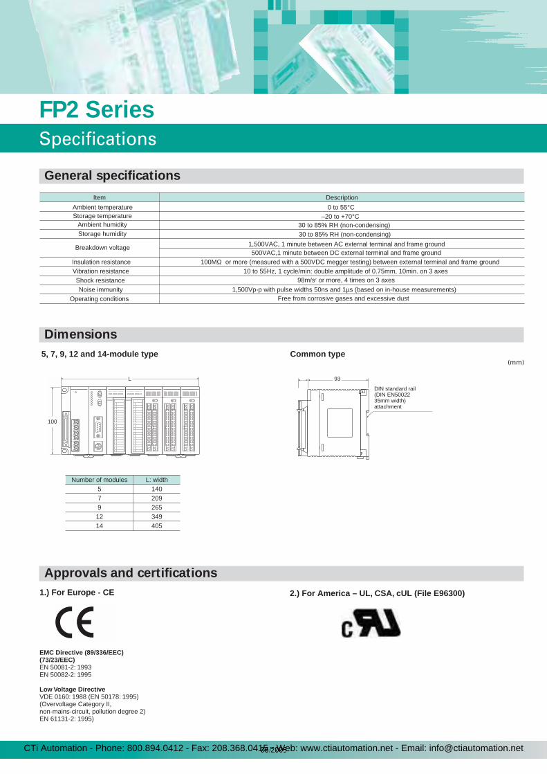
Item Description
Ambient temperature 0 to 55°CStorage temperature –20 to +70°C
Ambient humidity 30 to 85% RH (non-condensing)Storage humidity 30 to 85% RH (non-condensing)
Breakdown voltage 1,500VAC, 1 minute between AC external terminal and frame ground500VAC,1 minute between DC external terminal and frame ground
Insulation resistance 100MΩ or more (measured with a 500VDC megger testing) between external terminal and frame groundVibration resistance 10 to 55Hz, 1 cycle/min: double amplitude of 0.75mm, 10min. on 3 axesShock resistance 98m/s or more, 4 times on 3 axes2
Noise immunity 1,500Vp-p with pulse widths 50ns and 1µs (based on in-house measurements)Operating conditions Free from corrosive gases and excessive dust
5, 7, 9, 12 and 14-module type Common type
Number of modules L: width5 1407 2099 26512 34914 405
100
L 93
DIN standard rail(DIN EN5002235mm width)attachment
(mm)
1.) For Europe - CE
EMC Directive (89/336/EEC)(73/23/EEC)EN 50081-2: 1993EN 50082-2: 1995
Low Voltage DirectiveVDE 0160: 1988 (EN 50178: 1995)(Overvoltage Category II, non-mains-circuit, pollution degree 2) EN 61131-2: 1995)
2.) For America – UL, CSA, cUL (File E96300)
SpecificationsFP2 Series
General specifications
Dimensions
(mm)
Approvals and certifications
CTi Automation - Phone: 800.894.0412 - Fax: 208.368.0415 - Web: www.ctiautomation.net - Email: [email protected]
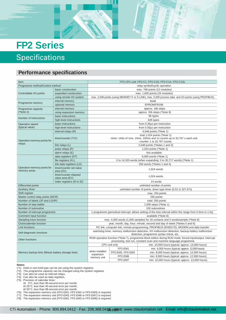
Notes:(*1): Hold or non-hold type can be set using the system registers.(*2): The programme capacity can be changed using the system registers.(*3): Can also be used as internal relays.(*4): Can also be used as data registers.(*5): Precision of calendar timer:
At 0°C, less than 90-second error per month. At 25°C, less than 40-second error per month. At 55°C, less than 98-second error per month.
(*6): The expansion memory unit (FP2-EM1, FP2-EM2 or FP2-EM3) is required.(*7): The expansion memory unit (FP2-EM3, FP2-EM6 or FP2-EM7) is required.(*8): The expansion memory unit (FP2-EM2, FP2-EM3 or FP2-EM6) is required.
Item FP2 CPU unit: FP2-C1, FP2-C1D, FP2-C1A, FP2-C1SLProgramme method/Control method relay symbol/cyclic operation
Controllable I/O pointsbasic construction max. 768 points (12 modules)expanded construction max. 1,600 points (25 modules)using remote I/O system max. 2,048 points (using MEWNET-F or S-LINK), max. 5,000 process data and I/O points (using PROFIBUS)
Programme memoryinternal memory RAMoptional memory EPROM/FROM
Programme capacity (*Note 2)
internal memory approx. 16k stepsusing expansion memory approx. 32k steps (*Note 8)
Number of instructionsbasic instructions 96 types
high-level instructions 428 types
Operation speed (typical value)
basic instructions from 0.35µs per instructionhigh-level instructions from 0.93µs per instruction
Operation memory points for relays
internal relays (R) 4,048 points (*Note 1)
timer/counter (T/C)total 1,024 points (*Note 1)
- timer: Units of 1ms, 10ms, 100ms and 1s counts up to 32,767 x each unit. - counter: 1 to 32,767 counts
link relays (L) 2,048 points (*Notes 1 and 3)pulse relays (P) 1,024 points (*Note 1)alarm relays (E) Not available
Operation memory points for memory areas
data registers (DT) 6,000 words (*Note 1)file registers (FL) 0 to 14,333 words (when expanding: 0 to 30,717 words) (*Note 1)
link data registers (LD) 256 words (*Notes 1 and 4)timer/counter set value area (SV)
1,024 words
timer/counter elapsed value area (EV) 1,024 words
index registers (I0 to ID) 14 wordsDifferential points unlimited number of pointsAuxiliary timer unlimited number of points, down type timer (0.01 to 327.67s)Shift register max. 253 pointsMaster control relay points (MCR) 256 pointsNumber of labels (JP and LOOP) total: 256 pointsNumber of step ladder 1,000 steps (*Note 1)Number of subroutine 100 subroutinesNumber of interrupt programme 1 programme (periodical interrupt: allows setting of the time interval within the range from 0.5ms to 1.5s)Comment input function available (*Note 6)Sampling trace function max. 4,000 words (1,000 samples) for 16 contacts and 3 words/sample (*Note 8)Clock/calendar function year, month, day, hour, minute, second and day of week (*Notes 5 and 6)Link functions PC link, computer link, remote programming, PROFIBUS (EN50170), MODEM and data transfer
Self-diagnostic functions watchdog timer, memory malfunction detection, I/O malfunction detection, backup battery malfunctiondetection, programme syntax check, etc.
Other functions ROM operation function (*Note 7), programme block edition during RUN mode, forced input/output, interrupt processing, test run, constant scan and machine language programme
Memory backup time (lithium battery storage time)
CPU unit only min. 10,000 hours (typical: approx. 13,000 hours)
when installed expansion
memory unit
FP2-EM1 min. 9,000 hours (typical: approx. 12,000 hours) FP2-EM2, FP2-EM3 min. 8,000 hours (typical: approx. 12,000 hours):
FP2-EM6 min. 8,500 hours (typical: approx. 12,500 hours): FP2-EM7 min. 10,000 hours (typical: approx. 13,000 hours)
11
FP2 Series
Specifications
Performance specifications
CTi Automation - Phone: 800.894.0412 - Fax: 208.368.0415 - Web: www.ctiautomation.net - Email: [email protected]
12
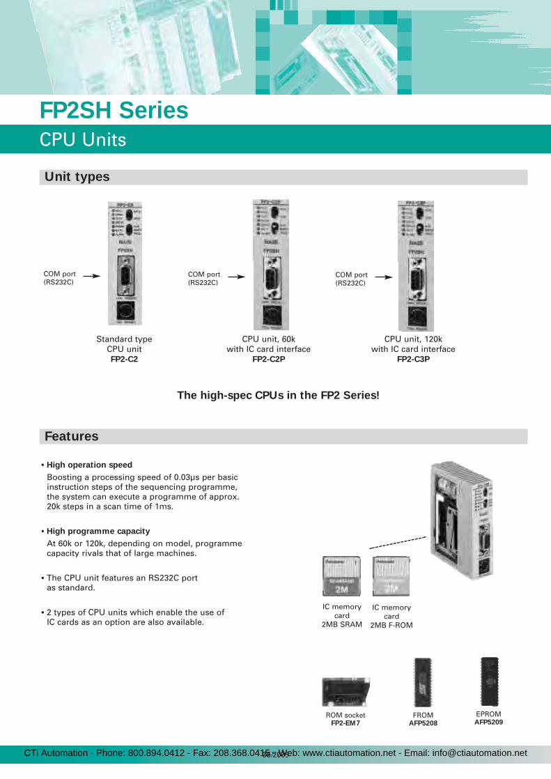
• High operation speed
Boosting a processing speed of 0.03µs per basicinstruction steps of the sequencing programme,the system can execute a programme of approx.20k steps in a scan time of 1ms.
• High programme capacity
At 60k or 120k, depending on model, programmecapacity rivals that of large machines.
• The CPU unit features an RS232C portas standard.
• 2 types of CPU units which enable the use ofIC cards as an option are also available.
FP2SH Series
CPU Units
Standard typeCPU unitFP2-C2
CPU unit, 60kwith IC card interface
FP2-C2P
CPU unit, 120kwith IC card interface
FP2-C3P
IC memorycard
2MB SRAM
IC memorycard
2MB F-ROM
Features
COM port(RS232C)
COM port(RS232C)
Unit types
COM port(RS232C)
The high-spec CPUs in the FP2 Series!
ROM socketFP2-EM7
FROMAFP5208
EPROMAFP5209
CTi Automation - Phone: 800.894.0412 - Fax: 208.368.0415 - Web: www.ctiautomation.net - Email: [email protected]

Notes:(*1): Hold or non-hold type can be set using the system registers.(*2): The programme capacity can be change using the system registers.(*3): Can also be used as internal relays.(*4): Can also be used as data registers.(*5): Precision of calendar timer:
At 0°C, less than 57-second error per month. At 25°C, less than 88-second error per month. At 55°C, less than 88-second error per month.
(*6): For FP2-C2 the expansion memory unit (FP2-EM7) is required.
Item FP2SH CPU unit: FP2-C2, FP2-C2P, FP2-C3P Programme method/Control method relay symbol/cyclic operation
Controllable I/O pointsbasic construction max. 768 points (12 modules)expanded construction max. 1,600 points (25 modules)
using remote I/O system max. 8,192 points (using MEWNET-F or S-LINK)
Programme memoryinternal memory RAMoptional memory EPROM/FROM
Programme capacity (*Note 2)
internal memory FP2-C2/FP2-C2P: approx. 60k steps, FP2-C3P: approx. 120k stepsusing expansion memory
Number of instructionsbasic instructions 95 typeshigh-level instructions 434 types
Operation speed (typical value)
basic instructions from 0.03µs per instruction
high-level instructions from 0.06µs per instruction
Operation memory points for relays
internal relays (R) 14,192 points (*Note 1)
timer/counter (T/C)total 3,072 points (*Note 1)
- timer: Units of 1ms, 10ms, 100ms and 1s counts up to 32,767 x each unit. - counter: 1 to 32,767 counts
link relays (L) 10,240 points (*Notes 1 and 3)pulse relays (P) 2,048 points (*Note 1)alarm relays (E
Operation memory points for memory areas
data registers (DT) 10,240 words (*Note 1)file registers (FL) 32,765 words x 3 banks
link data registers (LD) 8,448 words (*Notes 1 and 4)timer/counter set value area (SV)
3,072 words
timer/counter elapsed value area (EV) 3,072 words
index registers (I0 to ID) 14 words x 16 banksDifferential points unlimited number of pointsAuxiliary timer unlimited number of points, down type timer (0.01 to 327.67s)Shift register max. 887 pointsMaster control relay points (MCR) 256 points (For FP2-C3P: 1st program: 256 points / 2nd program: 256 points)Number of labels (JP and LOOP) 256 points (For FP2-C3P: 1st program: 256 points / 2nd program: 256 points)Number of step ladder 1,000 steps (For FP2-C3P: 1st program only)Number of subroutine 100 subroutines
Number of interrupt programme 1 programme (periodical interrupt: allows setting of the time interval within the range from 0.5ms to 1.5s)Comment input function available (internal function)
Clock/calendar function year, month, day, hour, minute, second and day of week (*Note 5)Link functions PC link, computer link, remote programming, PROFIBUS (EN50170), MODEM and data transfer
Self-diagnostic functions watchdog timer, memory malfunction detection, I/O malfunction detection, backup battery malfunctiondetection, programme syntax check, etc.
Other functions ROM operation function (*Note 6), forced input/output, interrupt processing, test run, constant scan andmachine language programme
Memory backup time (lithium battery storage time)CPU unit only min. 3,500 hours (typical: approx. 31,000 hours)
when installed expansion memory unit(FP2-EM7)
min. 3,500 hours (typical approx. 31,000 hours)
2,048 points (*Note 1)
-
1313
FP2SH Series
Specifications
FP2SH performance specifications
CTi Automation - Phone: 800.894.0412 - Fax: 208.368.0415 - Web: www.ctiautomation.net - Email: [email protected]
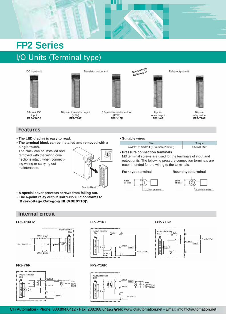
• The LED display is easy to read.• The terminal block can be installed and removed with a
single touch.The block can be installed and removed with the wiring con-nections intact, when connect-ing wiring or carrying out maintenance.
• A special cover prevents screws from falling out.• The 6-point relay output unit 'FP2-Y6R' conforms to'Overvoltage Category III (VDE0110)'.
• Suitable wires
• Pressure connection terminalsM3 terminal screws are used for the terminals of input and output units. The following pressure connection terminals are recommended for the wiring to the terminals.
Size TorqueAWG22 to AWG14 (0.3mm2 to 2.0mm2) 0.5 to 0.6Nm
Fork type terminal Round type terminal
6mmor less
3.2mm or more
6mmor less
3.2mm or more
16-point DCinput
FP2-X16D2
DC input unit Transistor output unit
16-point transistor output(NPN)
FP2-Y16T
16-point transistor output(PNP)
FP2-Y16P
6-pointrelay outputFP2-Y6R
16-pointrelay outputFP2-Y16R
Relay output unit
8
12 OPEN
Terminal block
Overvoltage
Categor y III
FP2 Series
I/O Units (Terminal type)
FP2-X16D2 FP2-Y16T FP2-Y16P
FP2-Y6R FP2-Y16R
12 to 24VDC
Input indicatorLED
Input 1.5kΩ
1kΩ0.1µF
1.5kΩCOM
Inte
rnal
circ
uit
5 to 24VDC
Output indicatorLED
Output
7.5kΩ
6.8kΩ
Load
Inte
rnal
circ
uit 5 to 24VDC
Output indicatorLED
Output
3.9kΩ
2.0kΩ
Load
Inte
rnal
circ
uit
24VDC
Output indicatorLED
Max.250VA30VDOutput
OutputLoad
Inte
rnal
circ
uit
24VDC
Output indicatorLED
Max.250VAC 2A30VDC 2AOutput
OutputLoad
Inte
rnal
circ
uit
Internal circuit
Features
CTi Automation - Phone: 800.894.0412 - Fax: 208.368.0415 - Web: www.ctiautomation.net - Email: [email protected]

Note:(see output specifications):
The load current will varydepending on the powersupply for driving theinternal circuit. Adjust theload current referring tothe following range.
Note:For each common 1 pin, use at a current capacity of 5A or less.
Item 16-point DC input type FP2-X16D2Insulation method optical couplerRated input voltage 12 to 24VDCRated input current approx. 8mA (at 24VDC)Input impedance approx. 3kΩInput voltage range 10.2 to 26.4VDC (max. input current: 10mA)Min. ON voltage/Min. ON current 9.6V/4mAMax. OFF voltage/Max. OFF current 2.5V/1mA
Response timeOFF => ON 0.2ms or lessON => OFF 0.2ms or less
Internal current consumption (at 5VDC) 60mA or less
Input points per common 8 points/common. Either the positive or negative of the input power supply can be connected to common terminal.
Operating indicator 16-dot LED display (lit when ON)Connection method terminal block (M3 screw)Weight approx. 140g
Item 16-point Transistor output (NPN) type FP2-Y16T 16-point Transistor output (PNP) type FP2-Y16PInsulation method optical coupler optical couplerRated load voltage 5 to 24VDC 5 to 24VDCLoad voltage range 4.75 to 26.4VDC 4.75 to 26.4VDCMaximum load current (*Note) 0.5A (at 12 to 24VDC), 0.1A (at 5VDC) 0.5A (at 12 to 24VDC), 0.1 A (at 5VDC)Maximum surge current 3A, 10ms or less 3A, 10ms or less
OFF state leakage current 1µA or less 1µA or lessON state maximum voltage drop 0.5V or less 0.5V or less
Response timeOFF => ON 0.1ms or less 0.1ms or less
ON => OFF 0.3ms or less 0.3ms or less
Internal current consumption (at 5VDC) 100mA or less 80mA or less
Power supply for driving internal circuit
Voltage 4.75 to 26.4VDC (*Note) 4.75 to 26.4VDC (*Note)Current 120mA or less (at 24VDC) 70mA or less (at 24VDC)
Surge absorber zener diode zener diode
Fuse ratings none none
Output points per common 8 points/common 8 points/commonOperating indicator 16-dot LED display (lit when ON) 16-dot LED display (lit when ON)
Connection method terminal block (M3 screw) terminal block (M3 screw)
Weight approx. 150g approx. 150g
Item 6-point Relay output type FP2-Y6R 16-point Relay output type FP2-Y16RInsulation method optical coupler optical coupler
Rated control capacity 5A 250VAC (10A/common), 5A 30VDC (10A/common) (*Note) min. load: 100mA, 10V (resistor load)
2A 250VAC (5A/common), 2A 30VDC (5A/common) min. load: 100µA, 100mV (resistor load)
Response timeOFF => ON 10ms or less 10ms or less
ON => OFF 8ms or less 8ms or less
Life timeMechanical 20,000,000 operations or more 20,000,000 operations or moreElectrical 100,000 operations or more 100,000 operations or more
Internal current consumption (at 5VDC) 50mA or less 120mA or less
Power supply for driving internal circuit
Voltage 24VDC ± 10% (21.6 to 26.4VDC) 24VDC ± 10% (21.6 to 26.4VDC)Current 70mA or less 160mA or less
Surge absorber none none
Relay socket without relay socket without relay socketOutput points per common 8 points/common 8 points/common
Operating indicator 6-dot LED display (lit when ON) 16-dot LED display (lit when ON)Connection method terminal block (M3 screw) terminal block (M3 screw)
Weight approx. 170g approx. 190g
4.75
500
Max
. loa
d cu
rren
t (m
A)
100
10.2 20.4Power supply for drivinginternal circuit (V)
Overvoltage
Categor y III
15
FP2 Series
I/O Units (Terminal type)
Input specifications
Output specifications
CTi Automation - Phone: 800.894.0412 - Fax: 208.368.0415 - Web: www.ctiautomation.net - Email: [email protected]
FP2 Series
I/O Units (Connector Type)
4.75
100
50
Max
. loa
d cu
rren
t (m
A)
10.2 26.4Power supply for drivinginternal circuit (V)
4.75
100
50
Max
. loa
d cu
rren
t (m
A)
10.2 26.4Power supply for drivinginternal circuit (V)
24VDC
26.4VDC
320
64
43
28
041 55
Ambient temperature (°C)
Number of points per common which are simultaneouslyON
FP2-Y64T24VDC
120
21
021 55
Ambient temperature (¡C)
Number of points per common which are simultaneouslyON 24
64
26.4VDC
FP2-Y64P
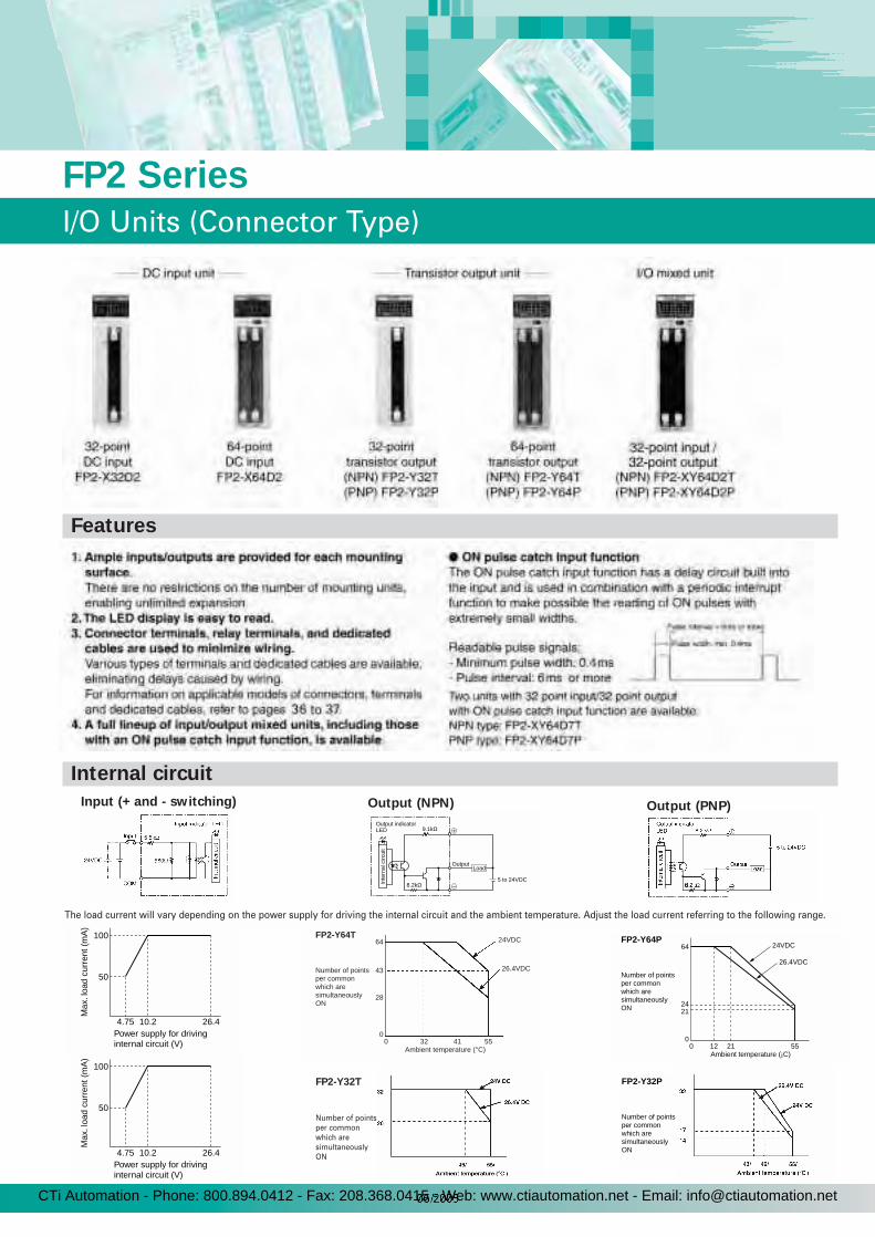
Input (+ and - switching)
5 to 24VDC
Output indicatorLED
Output
9.1kΩ
8.2kΩ
Load
Inte
rnal
circ
uit
Output (NPN) Output (PNP)
The load current will vary depending on the power supply for driving the internal circuit and the ambient temperature. Adjust the load current referring to the following range.
Number of points per common which are simultaneouslyON
FP2-Y32P
Features
FP2-Y32T
Number of pointsper commonwhich aresimultaneouslyON
Internal circuit
CTi Automation - Phone: 800.894.0412 - Fax: 208.368.0415 - Web: www.ctiautomation.net - Email: [email protected]
17
FP2 Series
I/O Units (Connector Type)
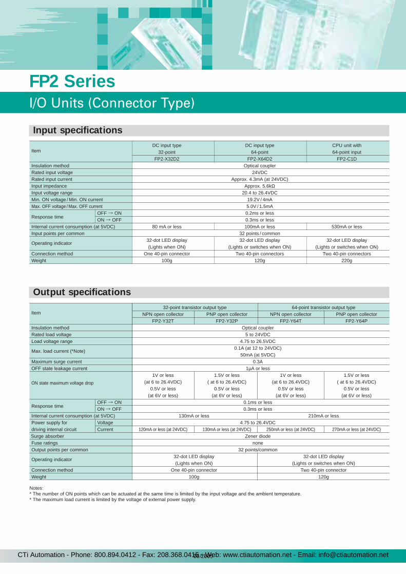
ItemDC input type DC input type CPU unit with
32-point 64-point 64-point inputFP2-X32D2 FP2-X64D2 FP2-C1D
Insulation method Optical couplerRated input voltage 24VDCRated input current Approx. 4.3mA (at 24VDC)Input impedance Approx. 5.6kΩInput voltage range 20.4 to 26.4VDCMin. ON voltage / Min. ON current 19.2V / 4mAMax. OFF voltage / Max. OFF current 5.0V / 1.5mA
OFF ON 0.2ms or lessResponse time
ON OFF 0.3ms or lessInternal current consumption (at 5VDC) 80 mA or less 100mA or less 530mA or lessInput points per common 32 points / common
Operating indicator32-dot LED display 32-dot LED display 32-dot LED display(Lights when ON) (Lights or switches when ON) (Lights or switches when ON)
Connection method One 40-pin connector Two 40-pin connectors Two 40-pin connectorsWeight 100g 120g 220g
Item32-point transistor output type 64-point transistor output type
NPN open collector PNP open collector NPN open collector PNP open collectorFP2-Y32T FP2-Y32P FP2-Y64T FP2-Y64P
Insulation method Optical couplerRated load voltage 5 to 24VDCLoad voltage range 4.75 to 26.5VDC
Max. load current (*Note)0.1A (at 12 to 24VDC)
50mA (at 5VDC)Maximum surge current 0.3AOFF state leakage current 1µA or less
ON state maximum voltage drop
1V or less 1.5V or less 1V or less 1.5V or less(at 6 to 26.4VDC) ( at 6 to 26.4VDC) (at 6 to 26.4VDC) ( at 6 to 26.4VDC)
0.5V or less 0.5V or less 0.5V or less 0.5V or less(at 6V or less) (at 6V or less) (at 6V or less) (at 6V or less)
OFF ON 0.1ms or lessResponse time
ON OFF 0.3ms or lessInternal current consumption (at 5VDC) 130mA or less 210mA or lessPower supply for Voltage 4.75 to 26.4VDCdriving internal circuit Current 120mA or less (at 24VDC) 130mA or less (at 24VDC) 250mA or less (at 24VDC) 270mA or less (at 24VDC)Surge absorber Zener diodeFuse ratings noneOutput points per common 32 points/common
Operating indicator32-dot LED display 32-dot LED display(Lights when ON) (Lights or switches when ON)
Connection method One 40-pin connector Two 40-pin connectorWeight 100g 120g
Notes:* The number of ON points which can be actuated at the same time is limited by the input voltage and the ambient temperature.* The maximum load current is limited by the voltage of external power supply.
Input specifications
Output specifications
CTi Automation - Phone: 800.894.0412 - Fax: 208.368.0415 - Web: www.ctiautomation.net - Email: [email protected]
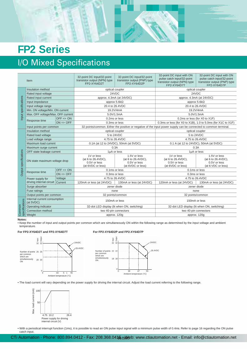
Item32-point DC input/32-point
transistor output (NPN) type FP2-XY64D2T
32-point DC input/32-point transistor output (PNP) type
FP2-XY64D2P
32-point DC input with ON pulse catch input/32-point
transistor output (NPN) type FP2-XY64D7T
32-point DC input with ON pulse catch input/32-point
transistor output (PNP) type FP2-XY64D7P
Inpu
t spe
cific
atio
ns
Insulation method optical coupler optical couplerRated input voltage 24VDC 24VDCRated input current approx. 4.3mA (at 24VDC) approx. 4.3mA (at 24VDC)Input impedance approx 5.6kΩ approx 5.6kΩInput voltage range 20.4 to 26.4VDC 20.4 to 26.4VDC Min. ON voltage/Min. ON current 19.2V/4mA 19.2V/4mAMax. OFF voltage/Max. OFF current 5.0V/1.5mA 5.0V/1.5mA
Response timeOFF => ON 0.2ms or less 0.2ms or less (for X0 to X1F)ON => OFF 0.3ms or less 0.3ms or less (for X0 to X1B), 1.0 to 5.0ms (for X1C to X1F)
Input points per common 32 points/common. Either the positive or negative of the input power supply can be connected to common terminal.
Out
put s
peci
ficat
ions
Insulation method optical coupler optical couplerRated load voltage 5 to 24VDC 5 to 24VDCLoad voltage range 4.75 to 26.4VDC 4.75 to 26.4VDCMaximum load current 0.1A (at 12 to 24VDC), 50mA (at 5VDC) 0.1 A (at 12 to 24VDC), 50mA (at 5VDC)Maximum surge current 0.3A 0.3AOFF state leakage current 1µA or less 1µA or less
ON state maximum voltage drop
1V or less (at 6 to 26.4VDC),
0.5V or less (at 6VDC or less)
1.5V or less (at 6 to 26.4VDC),
0.5V or less (at 6VDC or less)
1V or less (at 6 to 26.4VDC),
0.5V or less (at 6VDC or less)
1.5V or less (at 6 to 26.4VDC),
0.5V or less (at 6 VDC or less)
Response timeOFF => ON 0.1ms or less 0.1ms or lessON => OFF 0.3ms or less 0.3ms or less
Power supply for driving internal circuit
Voltage 4.75 to 26.4VDC 4.75 to 26.4VDCCurrent 120mA or less (at 24VDC) 130mA or less (at 24VDC) 120mA or less (at 24VDC) 130mA or less (at 24VDC)
Surge absorber zener diode zener diodeFuse ratings none noneOutput points per common 32 points/common 32 points/common
Com
mon
spec
ifica
tions
Internal current consumption (at 5VDC) 150mA or less 150mA or less
Operating indicator 32-dot LED display (lit when ON, switching) 32-dot LED display (lit when ON, switching)Connection method two 40-pin connectors two 40-pin connectorsWeight approx. 120g approx. 120g
Notes:• Keep the number of input and output points per common which are simultaneously ON within the following range as determined by the input voltage and ambient
temperature.
For FP2-XY64D2T and FP2-XY64D7T For FP2-XY64D2P and FP2-XY64D7P
24VDC
26.4VDC
430 5 1 55Ambient temperature (°C)
32
Out
put
Inpu
t
25
20
32
25
20
0
Number of points per common which are simultaneously ON
24VDC
26.4VDC
380
32
Out
put
Inpu
t
22
18
32
22
18
047 55
Ambient temperature (°C)
Number of points per common which are simultaneously ON
• The load current will vary depending on the power supply for driving the internal circuit. Adjust the load current referring to the following range.
4.75
100
50
Max
. loa
d cu
rren
t (m
A)
10.2 26.4Power supply for drivinginternal circuit (V)
• With a periodical interrupt function (1ms), it is possible to read an ON pulse input signal with a minimum pulse width of 0.4ms. Refer to page 16 regarding the ON pulsecatch input.
FP2 Series
I/O Mixed Specifications
CTi Automation - Phone: 800.894.0412 - Fax: 208.368.0415 - Web: www.ctiautomation.net - Email: [email protected]
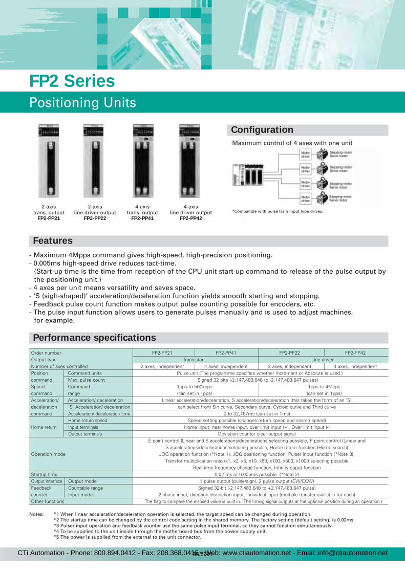
- Maximum 4Mpps command gives high-speed, high-precision positioning.- 0.005ms high-speed drive reduces tact-time.
(Start-up time is the time from reception of the CPU unit start-up command to release of the pulse output bythe positioning unit.)
- 4 axes per unit means versatility and saves space.- ‘S (sigh-shaped)’ acceleration/deceleration function yields smooth starting and stopping.- Feedback pulse count function makes output pulse counting possible for encoders, etc.- The pulse input function allows users to generate pulses manually and is used to adjust machines,
for example.
19
FP2 Series
Positioning Units
Maximum control of 4 axes with one unit
*Compatible with pulse train input type drives.2-axis
trans. outputFP2-PP21
2-axisline driver output
FP2-PP22
4-axistrans. output
FP2-PP41
4-axisline driver output
FP2-PP42
Order number FP2-PP21 FP2-PP41 FP2-PP22 FP2-PP42Output type Transistor Line driverNumber of axes controlled 2 axes, independent 4 axes, independent 2 axes, independent 4 axes, independentPosition Command units Pulse unit (The programme specifies whether Increment or Absolute is used.)command Max. pulse count Signed 32 bits (-2,147,483,648 to -2,147,483,647 pulses)Speed Command 1pps to 500kpps 1pps to 4Mppscommand range (can set in 1pps) (can set in 1pps)Acceleration/ Acceleration/ deceleration Linear acceleration/deceleration, S acceleration/deceleration (this takes the form of an ‘S’)deceleration ‘S’ Acceleration/ deceleration can select from Sin curve, Secondary curve, Cycloid curve and Third curvecommand Acceleration/ deceleration time 0 to 32,767ms (can set in 1ms)
Home return speed Speed setting possible (changes return speed and search speed)Home return Input terminals Home input, near home input, over limit input (+), Over limit input (-)
Output terminals Deviation counter clear output signalE point control (Linear and S accelerations/decelerations selecting possible, P point control (Linear and
S accelerations/decelerations selecting possible, Home return function (Home search)Operation mode JOG operation function (*Note 1), JOG positioning function, Pulser input function (*Note 3),
Transfer multiplication ratio (x1, x2, x5, x10, x50, x100, x500, x1000 selecting possibleReal-time frequency change function, Infinity ouput function
Startup time 0.02 ms or 0.005ms possible. (*Note 2)Output interface Output mode 1 pulse output (pulse/sign), 2 pulse output (CW/CCW)Feedback Countable range Signed 32-bit (-2,147,483,648 to +2,147,483,647 pulse)counter Input mode 2-phase input, direction distinction input, individual input (multiple transfer available for each)Other functions The flag to compare the elapsed value is built in. (The timing signal outputs at the optional position during an operation.)
Notes: *1 When linear acceleration/deceleration operation is selected, the target speed can be changed during operation.*2 The startup time can be changed by the control code setting in the shared memory. The factory setting (default setting) is 0.02ms.*3 Pulser input operation and feedback counter use the same pulse input terminal, so they cannot function simultaneously.*4 To be supplied to the unit inside through the motherboard bus from the power supply unit.*5 The power is supplied from the external to the unit connector.
Features
Performance specifications
Configuration
CTi Automation - Phone: 800.894.0412 - Fax: 208.368.0415 - Web: www.ctiautomation.net - Email: [email protected]
20
FP2 Series
High-Speed Counter Unit
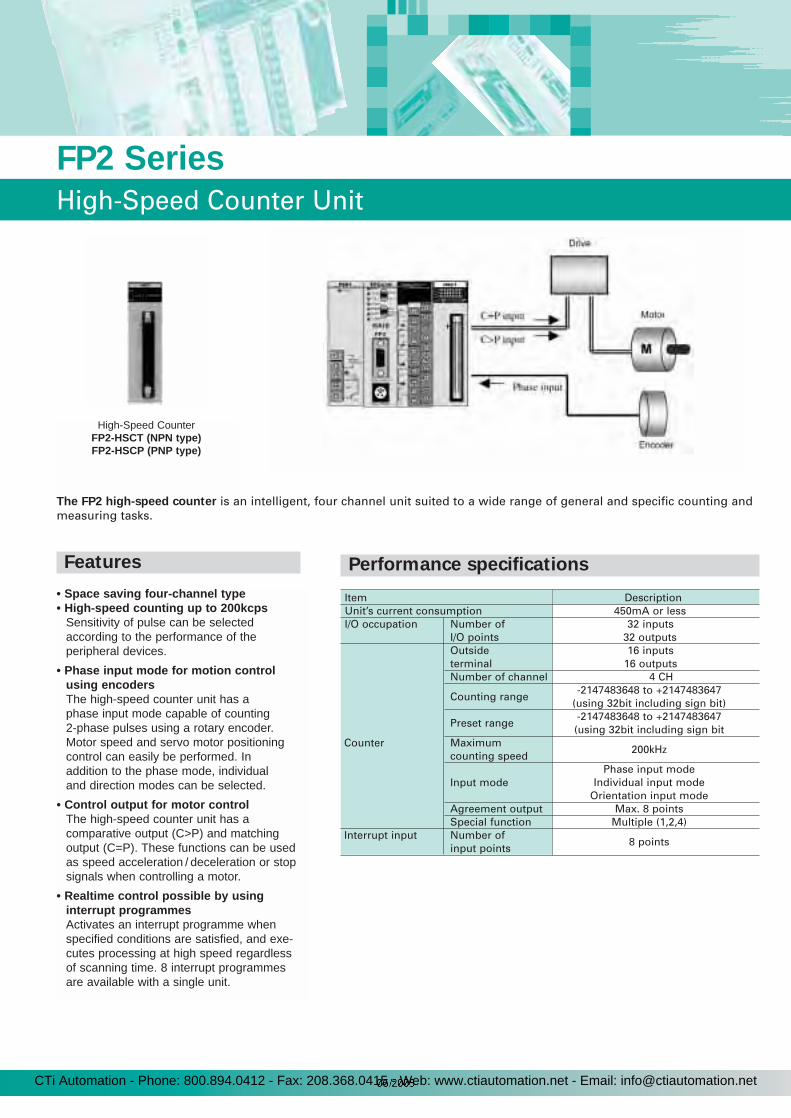
Item DescriptionUnit’s current consumption 450mA or lessI/O occupation Number of 32 inputs
I/O points 32 outputsOutside 16 inputsterminal 16 outputsNumber of channel 4 CH
Counting range-2147483648 to +2147483647
(using 32bit including sign bit)
Preset range-2147483648 to +2147483647(using 32bit including sign bit
Counter Maximum 200kHz
counting speed
Input modePhase input mode
Individual input modeOrientation input mode
Agreement output Max. 8 pointsSpecial function Multiple (1,2,4)
Interrupt input Number of 8 points
input points
The FP2 high-speed counter is an intelligent, four channel unit suited to a wide range of general and specific counting andmeasuring tasks.
• Space saving four-channel type• High-speed counting up to 200kcps
Sensitivity of pulse can be selectedaccording to the performance of the peripheral devices.
• Phase input mode for motion controlusing encodersThe high-speed counter unit has a phase input mode capable of counting 2-phase pulses using a rotary encoder. Motor speed and servo motor positioning control can easily be performed. In addition to the phase mode, individual and direction modes can be selected.
• Control output for motor controlThe high-speed counter unit has a comparative output (C>P) and matchingoutput (C=P). These functions can be usedas speed acceleration / deceleration or stopsignals when controlling a motor.
• Realtime control possible by usinginterrupt programmesActivates an interrupt programme when specified conditions are satisfied, and exe-cutes processing at high speed regardless of scanning time. 8 interrupt programmes are available with a single unit.
High-Speed CounterFP2-HSCT (NPN type)FP2-HSCP (PNP type)
Performance specificationsFeatures
CTi Automation - Phone: 800.894.0412 - Fax: 208.368.0415 - Web: www.ctiautomation.net - Email: [email protected]
21
FP2 Series
Pulse I/O Unit
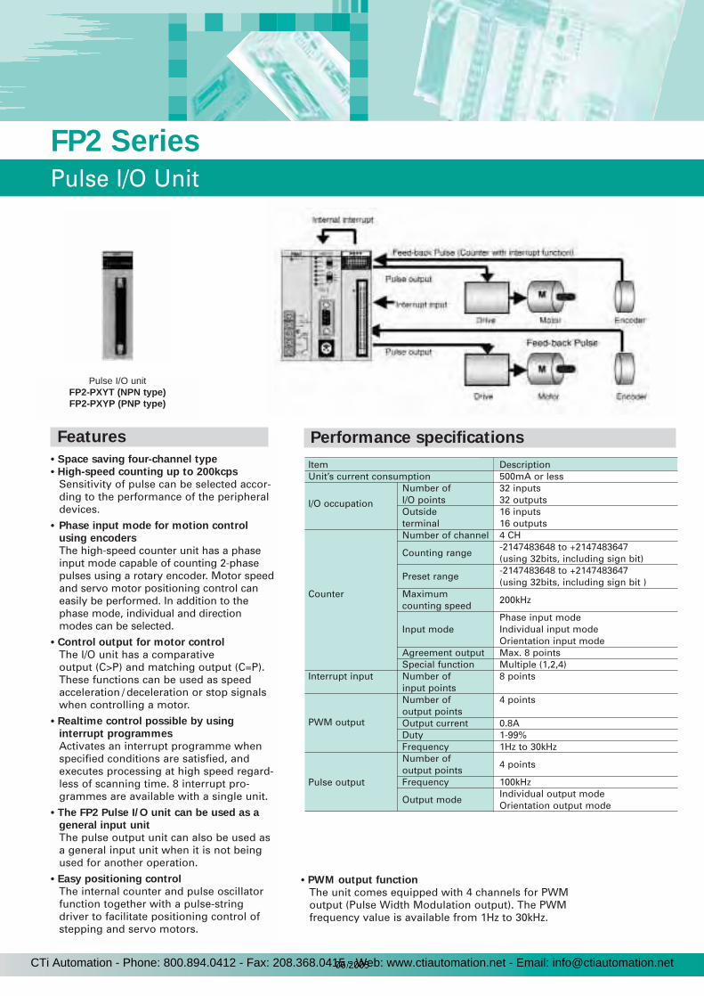
Item DescriptionUnit’s current consumption 500mA or less
I/O occupation
Number of 32 inputsI/O points 32 outputsOutside 16 inputsterminal 16 outputsNumber of channel 4 CH
Counting range-2147483648 to +2147483647(using 32bits, including sign bit)
Preset range-2147483648 to +2147483647(using 32bits, including sign bit )
Counter Maximum 200kHz
counting speed
Input modePhase input modeIndividual input modeOrientation input mode
Agreement output Max. 8 pointsSpecial function Multiple (1,2,4)
Interrupt input Number of 8 pointsinput points
PWM output
Number of 4 pointsoutput pointsOutput current 0.8ADuty 1-99%Frequency 1Hz to 30kHz
Pulse output
Number of 4 points
output pointsFrequency 100kHz
Output modeIndividual output modeOrientation output mode
• Space saving four-channel type
• High-speed counting up to 200kcps
Sensitivity of pulse can be selected accor-ding to the performance of the peripheraldevices.
• Phase input mode for motion control
using encoders
The high-speed counter unit has a phaseinput mode capable of counting 2-phasepulses using a rotary encoder. Motor speedand servo motor positioning control caneasily be performed. In addition to thephase mode, individual and directionmodes can be selected.
• Control output for motor control
The I/O unit has a comparative output (C>P) and matching output (C=P).These functions can be used as speed acceleration / deceleration or stop signalswhen controlling a motor.
• Realtime control possible by using
interrupt programmes
Activates an interrupt programme whenspecified conditions are satisfied, andexecutes processing at high speed regard-less of scanning time. 8 interrupt pro-grammes are available with a single unit.
• The FP2 Pulse I/O unit can be used as a
general input unit
The pulse output unit can also be used asa general input unit when it is not beingused for another operation.
• Easy positioning control
The internal counter and pulse oscillator function together with a pulse-stringdriver to facilitate positioning control ofstepping and servo motors.
Pulse I/O unitFP2-PXYT (NPN type)FP2-PXYP (PNP type)
• PWM output function
The unit comes equipped with 4 channels for PWMoutput (Pulse Width Modulation output). The PWMfrequency value is available from 1Hz to 30kHz.
Features Performance specifications
CTi Automation - Phone: 800.894.0412 - Fax: 208.368.0415 - Web: www.ctiautomation.net - Email: [email protected]
Analogue input unitFP2-AD8
Analogue output unitFP2-DA4
CPU unit with analogue I/OFP2-C1A
OUTPUT
+5V
0-10W
shitaPMS Ltd
ON
OFF
SPEED
1KHz100Hz10Hz
GAIN
HIGHARTLOW
ANAROGLM100
ZEARD ART
+–
RANGE
LANG EM15M
BRIGHT
DARK
LASERSENSOR
PanasonicAC SERVO DRIVERDV40P 005LD2A
AC100V
UP
DN
SEL
BASPMIM
GND
CN2I/F
PG
CN1SIG
R
T
r
t
U
V
W
E
M
SUHX DPX-200A
cmHg
Laser analoguesensor
Pressure sensor
Inverter
Analogue inputservo driver
Servo motor
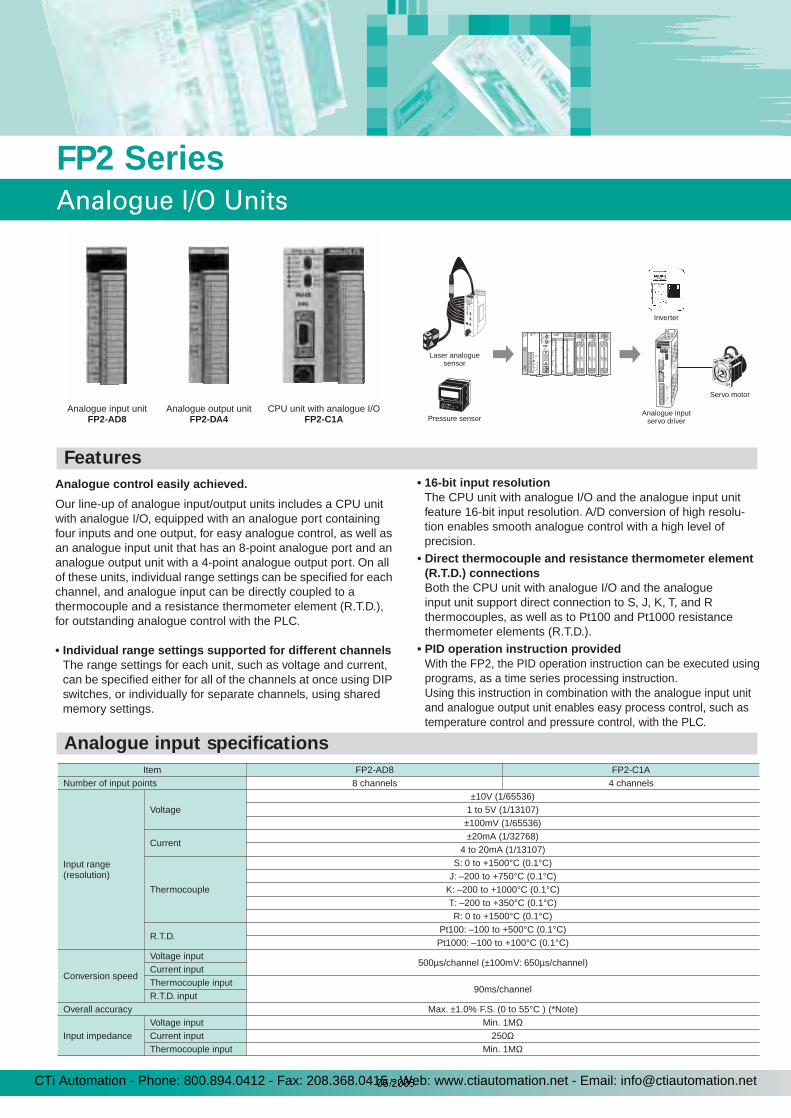
Analogue control easily achieved.
Our line-up of analogue input/output units includes a CPU unit with analogue I/O, equipped with an analogue port containing four inputs and one output, for easy analogue control, as well as an analogue input unit that has an 8-point analogue port and an analogue output unit with a 4-point analogue output port. On all of these units, individual range settings can be specified for each channel, and analogue input can be directly coupled to a thermocouple and a resistance thermometer element (R.T.D.), for outstanding analogue control with the PLC.
• Individual range settings supported for different channelsThe range settings for each unit, such as voltage and current, can be specified either for all of the channels at once using DIP switches, or individually for separate channels, using shared memory settings.
• 16-bit input resolutionThe CPU unit with analogue I/O and the analogue input unit feature 16-bit input resolution. A/D conversion of high resolu-tion enables smooth analogue control with a high level of precision.
• Direct thermocouple and resistance thermometer element (R.T.D.) connectionsBoth the CPU unit with analogue I/O and the analogue input unit support direct connection to S, J, K, T, and R thermocouples, as well as to Pt100 and Pt1000 resistance thermometer elements (R.T.D.).
• PID operation instruction providedWith the FP2, the PID operation instruction can be executed using
programs, as a time series processing instruction. Using this instruction in combination with the analogue input unit and analogue output unit enables easy process control, such as temperature control and pressure control, with the PLC.
Item FP2-AD8 FP2-C1ANumber of input points 8 channels 4 channels
Input range (resolution)
Voltage±10V (1/65536)
1 to 5V (1/13107)±100mV (1/65536)
Current±20mA (1/32768)
4 to 20mA (1/13107)
Thermocouple
S: 0 to +1500°C (0.1°C)J: –200 to +750°C (0.1°C)
K: –200 to +1000°C (0.1°C)T: –200 to +350°C (0.1°C)R: 0 to +1500°C (0.1°C)
R.T.D.Pt100: –100 to +500°C (0.1°C)
Pt1000: –100 to +100°C (0.1°C)
Conversion speed
Voltage input500µs/channel (±100mV: 650µs/channel)
Current inputThermocouple input
90ms/channelR.T.D. input
Overall accuracy Max. ±1.0% F.S. (0 to 55°C ) (*Note)
Input impedanceVoltage input Min. 1MΩCurrent input 250ΩThermocouple input Min. 1MΩ
FP2 Series
Analogue I/O Units
Features
Analogue input specifications
CTi Automation - Phone: 800.894.0412 - Fax: 208.368.0415 - Web: www.ctiautomation.net - Email: [email protected]
23
FP2 Series
Analogue I/O Units
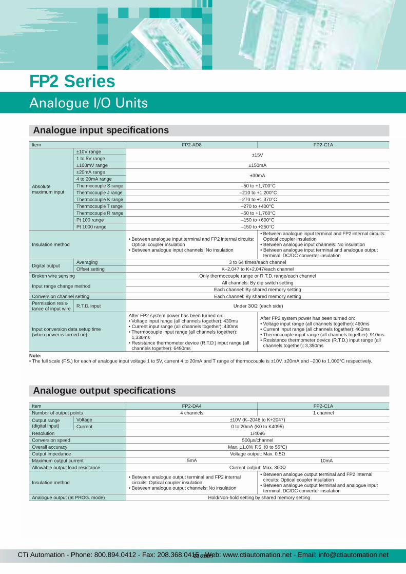
Note:• The full scale (F.S.) for each of analogue input voltage 1 to 5V, current 4 to 20mA and T range of thermocouple is ±10V, ±20mA and –200 to 1,000°C respectively.
Absolutemaximum input
±10V range±15V
1 to 5V range±100mV range ±150mA±20mA range
±30mA4 to 20mA rangeThermocouple S range –50 to +1,700°CThermocouple J range –210 to +1,200°C Thermocouple K range –270 to +1,370°CThermocouple T range –270 to +400°CThermocouple R range –50 to +1,760°CPt 100 range –150 to +600°CPt 1000 range –150 to +250°C
Insulation method• Between analogue input terminal and FP2 internal circuits:
Optical coupler insulation• Between analogue input channels: No insulation
• Between analogue input terminal and FP2 internal circuits: Optical coupler insulation
• Between analogue input channels: No insulation• Between analogue input terminal and analogue output
terminal: DC/DC converter insulation
Digital outputAveraging 3 to 64 times/each channelOffset setting K–2,047 to K+2,047/each channel
Broken wire sensing Only thermocouple range or R.T.D. range/each channel
Input range change methodAll channels: By dip switch setting
Each channel: By shared memory settingConversion channel setting Each channel: By shared memory settingPermission resis-tance of input wire R.T.D. input Under 30Ω (each side)
Input conversion data setup time (when power is turned on)
After FP2 system power has been turned on:• Voltage input range (all channels together): 430ms• Current input range (all channels together): 430ms• Thermocouple input range (all channels together):
1,330ms• Resistance thermometer device (R.T.D.) input range (all
channels together): 6490ms
After FP2 system power has been turned on:• Voltage input range (all channels together): 460ms• Current input range (all channels together): 460ms• Thermocouple input range (all channels together): 910ms• Resistance thermometer device (R.T.D.) input range (all
channels together): 3,350ms
Item FP2-AD8 FP2-C1A
Item FP2-DA4 FP2-C1ANumber of output points 4 channels 1 channel
Output range (digital input)
Voltage ±10V (K–2048 to K+2047)Current 0 to 20mA (K0 to K4095)
Resolution 1/4096Conversion speed 500µs/channelOverall accuracy Max. ±1.0% F.S. (0 to 55°C)Output impedance Voltage output: Max. 0.5ΩMaximum output current 10mAAllowable output load resistance Current output: Max. 300Ω
Insulation method• Between analogue output terminal and FP2 internal
circuits: Optical coupler insulation• Between analogue output channels: No insulation
• Between analogue output terminal and FP2 internal circuits: Optical coupler insulation
• Between analogue output terminal and analogue input terminal: DC/DC converter insulation
Analogue output (at PROG. mode) Hold/Non-hold setting by shared memory setting
5mA
Analogue input specifications
Analogue output specifications
CTi Automation - Phone: 800.894.0412 - Fax: 208.368.0415 - Web: www.ctiautomation.net - Email: [email protected]
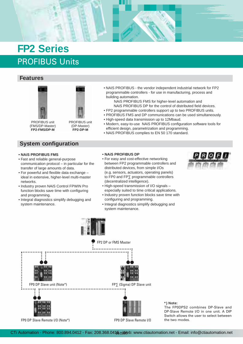
• NAIS PROFIBUS - the vendor independent industrial network for FP2programmable controllers - for use in manufacturing, process and building automation.
NAiS PROFIBUS FMS for higher-level automation and NAiS PROFIBUS DP for the control of distributed field devices.• FP2 programmable controllers support up to two PROFIBUS units.• PROFIBUS FMS and DP communications can be used simultaneously.• High-speed data transmission up to 12Mbaud.• Modern, easy-to-use NAiS PROFIBUS configuration software tools for
efficient design, parametrization and programming. • NAiS PROFIBUS complies to EN 50 170 standard.
• NAiS PROFIBUS FMS• Fast and reliable general-purpose
communication protocol – in particular for the transfer of large amounts of data.
• For powerful and flexible data exchange – ideal in extensive, higher-level multi-master networks.
• Industry proven NAiS Control FPWIN Pro function blocks save time with configuring and programming.
• Integral diagnostics simplify debugging and system maintenance.
• NAiS PROFIBUS DP• For easy and cost-effective networking
between FP2 programmable controllers and distributed devices, from simple I/Os (e.g. sensors, actuators, operating panels) to FP0 and FP∑ programmable controllers(decentralized intelligence).
• High-speed transmission of I/O signals – especially suited to time critical applications.
• Industry proven function blocks save time with
• Integral diagnostics simplify debugging and system maintenance.
PROFIBUS unit(DP-Master)FP2-DP-M
PROFIBUS unit(FMS/DP-Master)FP2-FMS/DP-M
configuring and programming.
FP2 Series
PROFIBUS Units
Features
System configuration
FP0 DP Slave unit (Note*) FP∑ (Sigma) DP Slave unit
FP0 DP Slave Remote I/O (Note*) FP0 DP Slave Remote I/O
FP2 DP or FMS Master
*) Note:
The FP0DPS2 combines DP-Slave andDP-Slave Remote I/O in one unit. A DIPSwitch allows the user to select betweenthe two modes.
CTi Automation - Phone: 800.894.0412 - Fax: 208.368.0415 - Web: www.ctiautomation.net - Email: [email protected]

FP2-FMS/DP-M FP2-DP-MAvailable PROFIBUSprotocols and functions
PROFIBUS FMS and DP (Master)(can be used at the same time) PROFIBUS DP (Master)
Number of PROFIBUS unit per one CPU unit Max. 2 units
FP2-FMS/DP-M FP2-DP-MUsing PROFIBUS protocol FMS DP (Master) DP (Master)Communication method Token passing Polling method Polling methodTransmission speed (Baud rate) 9.6kbps to 12Mbps
Transmission distance
based on PROFIBUS standard EN 50 170, e.g.PROFIBUS copper cable: 1,200m (9.6kbps, no repeater),PROFIBUS copper cable: 4,800m (9.6kbps, 3 repeaters),PROFIBUS copper cable: 100m (12Mbps, no repeater),PROFIBUS copper cable: 400m (12Mbps, 3 repeaters),
Optical fibre cable (plastic): 60m (1.5Mbps per segment),Optical fibre cable (glass): 2,850m (1.5Mbps per segment),
Optical fibre cable (glass, special type): 15,000m (1.5Mbps per segment)Number of stations (nodes) / open connections
125 stations with 64 open connections 125 slave stations 125 slave stations
PROFIBUS interface RS485 (SUB-D 9-pin socket)Communication path PROFIBUS cable (according to EN 50 170)
Note: 1) default setting
FP2-FMS/DP-M FP2-DP-MUsing PROFIBUS protocol FMS DP (Master) DP (Master)Controllable PROFIBUS data types per one unit 1)
1,024 input objects1,024 output objects
256 input process data256 output process data
256 input process data256 output process data
Used memory areas1,024 words1,024 words
256 words256 words
256 words256 words
Setting method using NAiS FPWIN Pro and NAIS PROFIBUS Tool
Movement status andcontrol / error alert
Area of use Special internal relays, special data registersRead / Writemethod using NAiS FPWIN Pro PROFIBUS function blocks
Data transfer capacity 238 bytes
Link registers
25
FP2 Series
PROFIBUS Specifications
General
Transmission specifications
Performance specifications
CTi Automation - Phone: 800.894.0412 - Fax: 208.368.0415 - Web: www.ctiautomation.net - Email: [email protected]
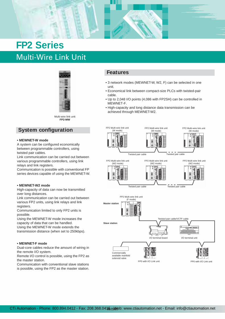
Multi-wire link unitFP2-MW
• 3 network modes (MEWNET-W, W2, F) can be selected in one unit.
• Economical link between compact-size PLCs with twisted-pair cable.
• Up to 2,048 I/O points (4,086 with FP2SH) can be controlled in
• High-capacity and long distance data transmission can be achieved through MEWNET-W2.
• MEWNET-W modeA system can be configured economically between programmable controllers, using twisted pair cables.Link communication can be carried out between various programmable controllers, using link relays and link registers.Communication is possible with conventional FP series devices capable of using the MEWNET-W.
• MEWNET-W2 modeHigh-capacity of data can now be transmitted over long distances.Link communication can be carried out between various FP2 units, using link relays and link registers.Communication limited to only FP2 units is possible.Using the MEWNET-W mode increases the capacity of data that can be handled.Using the MEWNET-W mode extends the transmission distance (when set to 250kbps).
• MEWNET-F modeDual-core cables reduce the amount of wiring in the remote I/O system.Remote I/O control is possible, using the FP2 as the master station.Communication with conventional slave stations is possible, using the FP2 as the master station.
FP2 Multi-wire link unit(W mode)
Twisted pair cable
FP2 Multi-wire link unit(W2 mode)
FP2 Multi-wire link unit(W2 mode)
FP2 Multi-wire link unit(W2 mode)
Twisted pair cable Twisted pair cable
FP2 Multi-wire link unit(F mode)
Master station
Slave station
FP0 with I/O Link unit FP0 with I/O Link unit
Commerciallyavailable manifoldsolenoid valve
Twisted pair cable/VCTF cable
I/O terminal board I/O terminal unit
MEWNET-F.
FP2 Multi-wire link unit(W mode)
FP2 Multi-wire link unit(W mode)
Twisted pair cable
FP2 Series
Multi-Wire Link Unit
Features
System configuration
CTi Automation - Phone: 800.894.0412 - Fax: 208.368.0415 - Web: www.ctiautomation.net - Email: [email protected]

Item W mode W2 mode F modeCommunication method Token bus method Polling methodTransmission method Baseband transmission methodTransmission speed (Baud rate) 500kbps 500kbps/250kbps 500kbps
Transmission distance Total length: max. 800mTotal length: max. 1,200m (at 250kbps)
800m (at 500kbps)Total length: max. 700m
Number of slave stations Max. 32 stations One master unit and max. 32 slave stationsError check method CRC (Cyclic Redundancy Check) methodSynchronized method Start-stop synchronous systemInterface Conforming to RS485Communication path Twisted pair cable Twisted pair cable, VCTF cableRAS function Hardware self-diagnostic function
W and W2 Modes
F Mode
ItemSpecification
W mode W2 modeCommunication functions PC link, Computer link, Data transfer, Remote programming, Hierarchical link
Functions/number of stations
PC link Max. 16 stations Max. 32 stationsOther functions Max. 32 stations
PC link
Area of useLink relays Fixed at WL
Set by selecting among WL, WR, LD, DT and FL.Link registers Fixed at LD
Setting method Setting using system register Setting using F145 (SEND)/P145 (PSEND) instruction.
CapacityLink relays Max. 1,024 points Max. 4,096 pointsLink registers Max. 128 words Max. 4,096 words
Movement status/error alert
Area of use Special internal relays, Special data registersSpecial internal relays, Special data registers, Detailed information is output to WL, WR, LD, DT, or FL, depending on the setting.
Setting method — Specified using F145 (SEND)/P145 (PSEND) instruction.Data transfer capacity Max. 16 words Max. 1,020 words
Item SpecificationControllable points per one CPU unit Max. 2,048 pointsControllable points per one unit Max. 2,048 pointsControllable slots per one CPU unit Max. 128 slotsControllable slots per one unit Max. 64 slotsControllable master units per one CPU unit Max. 4 units
27
FP2 Series
Multi-Wire Link Unit
Transmission specifications
Performance specifications
CTi Automation - Phone: 800.894.0412 - Fax: 208.368.0415 - Web: www.ctiautomation.net - Email: [email protected]
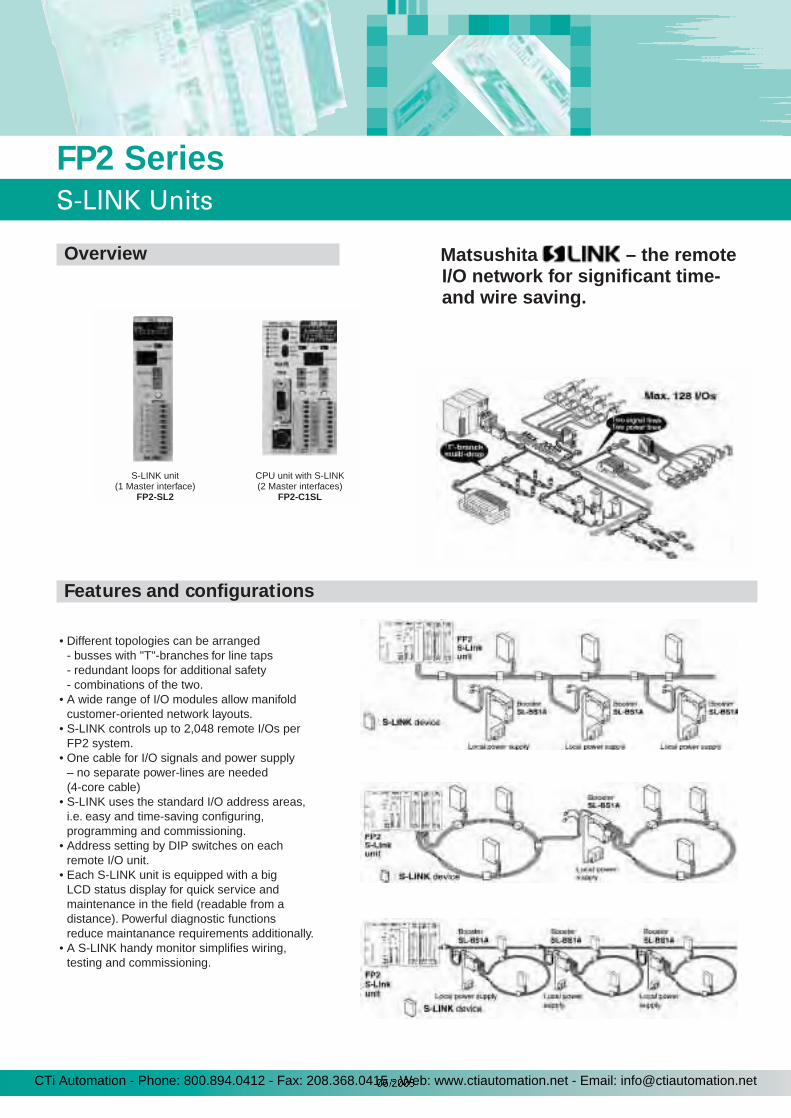
Matsushita – the remote I/O network for significant time- and wire saving.
• Different topologies can be arranged- busses with "T"-branches for line taps- redundant loops for additional safety- combinations of the two.
• A wide range of I/O modules allow manifold customer-oriented network layouts.
• S-LINK controls up to 2,048 remote I/Os perFP2 system.
• One cable for I/O signals and power supply– no separate power-lines are needed (4-core cable)
• S-LINK uses the standard I/O address areas, i.e. easy and time-saving configuring, programming and commissioning.
• Address setting by DIP switches on each remote I/O unit.
• Each S-LINK unit is equipped with a big LCD status display for quick service and maintenance in the field (readable from a distance). Powerful diagnostic functions reduce maintanance requirements additionally.
• A S-LINK handy monitor simplifies wiring, testing and commissioning.
S-LINK unit(1 Master interface)
FP2-SL2
CPU unit with S-LINK(2 Master interfaces)
FP2-C1SL
FP2 Series
S-LINK Units
Overview
Features and configurations
CTi Automation - Phone: 800.894.0412 - Fax: 208.368.0415 - Web: www.ctiautomation.net - Email: [email protected]
Notes: 1) For detailed information on current consumption, refer to "Determining the Power Supply Capacitance“ in the S-LINK design manual.2) For information on the booster and FAN-out, refer to the S-LINK design manual.3) The number of input and output points is automatically reflected in input X and output Y.
Unit type FP2-SL2 (S-Link unit) FP2-C1SL (CPU)Number of S-LINK interfaces 1 2
Input / output points
max. 128 E/A Max. 2 x 128 E/AThe number of I/O can be selected via the rotary switch (for each channel)
Input: 0/32/64/128 per unitOutput: 0/32/64/128 per unit
(16 input and 16 output points are also possible)total: 2,048 I/O per FP2 system
Rated voltage +24VDC +/- 10% / allowable ripple max. +/- 10%
Current consumption 1)S-LINK Controller: 24VDC, max. 1.6A
I/O-module: 24VDC, max. 5A (fuse 5A)Transmission protocol S-LINK protocolTransmission speed 28.5kbpsTransmission distance 2) 128 I/O signals can be transmitted over a pair of wires up to a distance to 200m max. (400m when a booster is used)FAN-out 2) 320
Connection method 'T'-branch multi-drop wiring or multi-drop wiring (+24V / 0V / D-G line [function provided to protect against short-circuiting between D-G line])
Interface with FP2 CPU 3) Common memory system Loading possible through F150 and P150; writing possible through F151 and P151
29
FP2 Series
S-LINK Units / ET-LAN Unit
Item DescriptionUnit’s current consumption 670mA or less
Communication interface10 BASE5
(only 1 port can be used at a time)10 BASE-T
100 BASE-TXCommunication protocol TCP / UPD / IP
MEWTOCOL Computer Link: Max. 2k bytescommunication Data transfer: Max. 1,020 wordsTransparent Max. 6k wordscommunication
FunctionsNumber of Max. 8 connectionsconnectionsRemote Max. 3 connections programming
Installation limitationFP2: Max. 3 units
FP2SH: Max. 5 units
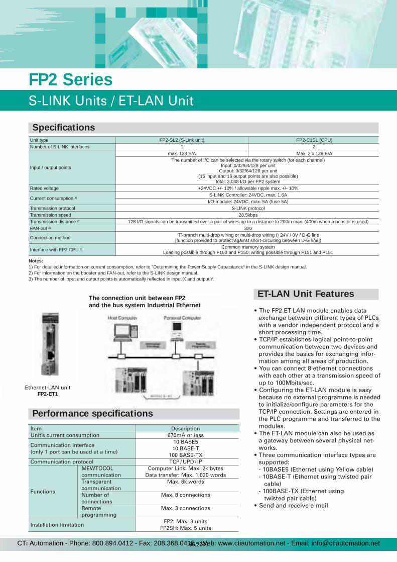
• The FP2 ET-LAN module enables dataexchange between different types of PLCswith a vendor independent protocol and ashort processing time.
• TCP/IP establishes logical point-to-point communication between two devices and provides the basics for exchanging infor-mation among all areas of production.
• You can connect 8 ethernet connectionswith each other at a transmission speed ofup to 100Mbits/sec.
• Configuring the ET-LAN module is easybecause no external programme is neededto initialize/configure parameters for theTCP/IP connection. Settings are entered inthe PLC programme and transferred to themodules.
• The ET-LAN module can also be used asa gateway between several physical net-works.
• Three communication interface types are supported:- 10BASE5 (Ethernet using Yellow cable)- 10BASE-T (Ethernet using twisted pair
cable)- 100BASE-TX (Ethernet using
twisted pair cable)• Send and receive e-mail.
Ethernet-LAN unitFP2-ET1
The connection unit between FP2
and the bus system Industrial Ethernet
Specifications
Performance specifications
ET-LAN Unit Features
CTi Automation - Phone: 800.894.0412 - Fax: 208.368.0415 - Web: www.ctiautomation.net - Email: [email protected]

The host computer(Commercial personal computer)
Operation display panel(HMI)
Computer Communication UnitFP2-CCU
• Connectable with operation display panel (HMI)
• Economical peer-to-peer communi-cation with a personal computer is possible.This unit can be directly connected with a personal computer via RS232C to collect and write data without building up a large-scale network.
• No communication programme is needed on the PLC. (Computer link function)The PLC automatically returns responses using the Matsushita FP Series’ MEWTCOOL communication procedure so that there’s no need to prepare a communication programme at the side of the PLC.
• Data transmission from the PLC is also possible (Data transfer func-tion).Since requests by the PLC for sending and receiving data are possible, theycommunicate only when necessary, e.g. to send an alarm. This reduces the burden on the personal computer.
• Connection with modemIt is possible to receive data over public
telephone lines from another PLC by
connecting a modem with your PLC(receiving only).
Item DescriptionInterface Two RS232C ports
Transmission speed (Baud rate) 19,200/9,600/4,800bps, selectable using dip switchCommunication method Half duplex
Communications Start-stop transmissionTransmission format ASCII
Transmission data framing
Stop bit 1-bitParity Valid (odd)Character bits 7-bit/8-bit, selectable using dip switch
Data transmission order 0 bit first in units of charactersEnd terminal code CR (0DH)
Computer Link format
Message Header(%) to terminator (CR)Maximum message length Max. 118 characters/frame (including “%” and “CR”)
Data Transfer format
Message Header(%) to terminator (CR)
Maximum message length Max. 240 characters/frame (including “%” and “CR”)
FP2 Series
Computer Communication Unit
Configuration
Features
Performance specifications
CTi Automation - Phone: 800.894.0412 - Fax: 208.368.0415 - Web: www.ctiautomation.net - Email: [email protected]

Serial Data UnitFP2-SDU
RS232C cable
Data readout withF150 instruction
Data write withF151 instruction
With shared memory, data is exchanged with the CPU
Micro-Imagechecker
Bar Code Reader
Printer
• Data input/output is executed by sequence command Reading can be performed simply by using applied command (F150), and writing by using applied command (F151). Since the subsequent process-ing is performed by the serial data unit through memory shared by the CPU unit, it is not necessary to work out a complicated programme.
• Free combination of I/O devices It is possible to use it in three ways: input only, output only, and input and output
• 500 bytes of data can be trans-mitted and received at a time
• No limitation on the number of units used
The number of serial data units used islimited to the number of free slots only.
Note:Selects the transmission speed “300/600/1,200/2,400bps”, stop bit “2-bit”, parity “invalid, even” and end “terminal code” optional code, CR + LF, ETX using shared memory.
Item DescriptionInterface Two RS232C portsTransmission speed (Baud rate) 19,200/9,600/4,800bps, selectable using dip switch (*Note)Communication method Half duplex
Communications Start-stop transmissionTransmission format ASCII
Transmission data framing
Stop bit 1-bit (*Note)Parity Valid (odd) (*Note)Character bits 7-bit/8-bit, selectable using dip switch
Data transmission order 0 bit first in units of characters
Transmission unit In units of messages to the end terminal code(Length can be changed.)
End terminal code CR (0DH) (*Note)
Maximum message length Max. 500 characters/frame (including end and start terminal codes)
Interface with FP2 CPU unit Shared memory method (data read out and write using F150/F151 instruction)
I/O allocation X: 16 points/Y: 16 points
31
FP2 Series
Serial Data Unit
Features
Performance specifications
Configuration
CTi Automation - Phone: 800.894.0412 - Fax: 208.368.0415 - Web: www.ctiautomation.net - Email: [email protected]
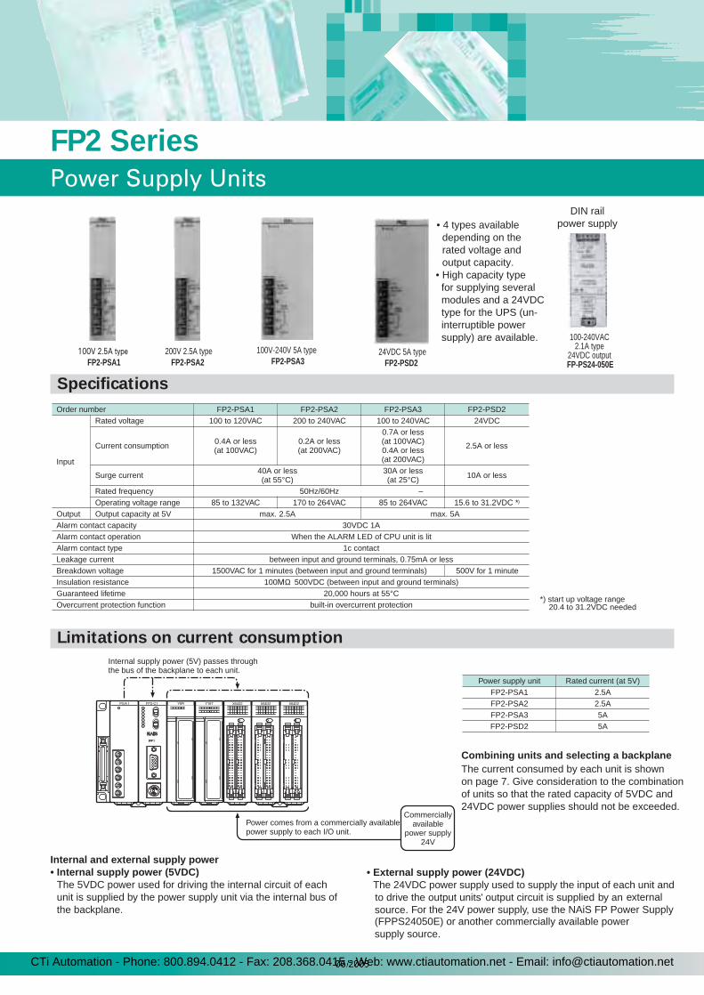
• 4 types available depending on the rated voltage and output capacity.• High capacity type for supplying several modules and a 24VDC type for the UPS (un- interruptible power supply) are available.
Order number FP2-PSA1 FP2-PSA2 FP2-PSA3 FP2-PSD2
Input
Rated voltage 100 to 120VAC 200 to 240VAC 100 to 240VAC 24VDC
Current consumption 0.4A or less (at 100VAC)
0.2A or less (at 200VAC)
0.7A or less (at 100VAC) 0.4A or less (at 200VAC)
2.5A or less
Surge current 40A or less (at 55°C)
30A or less (at 25°C) 10A or less
Rated frequency 50Hz/60Hz –Operating voltage range 85 to 132VAC 170 to 264VAC 85 to 264VAC 15.6 to 31.2VDC *)
Output Output capacity at 5V max. 2.5A max. 5AAlarm contact capacity 30VDC 1AAlarm contact operation When the ALARM LED of CPU unit is litAlarm contact type 1c contactLeakage current between input and ground terminals, 0.75mA or lessBreakdown voltage 1500VAC for 1 minutes (between input and ground terminals) 500V for 1 minuteInsulation resistance 100 MΩ 500VDC (between input and ground terminals)Guaranteed lifetime 20,000 hours at 55°COvercurrent protection function built-in overcurrent protection
Power supply unit Rated current (at 5V)FP2-PSA1 2.5AFP2-PSA2 2.5AFP2-PSA3 5AFP2-PSD2 5A
Internal supply power (5V) passes throughthe bus of the backplane to each unit.
Power comes from a commercially availablepower supply to each I/O unit.
Commerciallyavailable
power supply24V
Internal and external supply power• Internal supply power (5VDC)
The 5VDC power used for driving the internal circuit of each unit is supplied by the power supply unit via the internal bus of the backplane.
• External supply power (24VDC)The 24VDC power supply used to supply the input of each unit and to drive the output units' output circuit is supplied by an externalsource. For the 24V power supply, use the NAiS FP Power Supply
Combining units and selecting a backplane
The current consumed by each unit is shownon page 7. Give consideration to the combinationof units so that the rated capacity of 5VDC and24VDC power supplies should not be exceeded.
*) start up voltage range 20.4 to 31.2VDC needed
100V 2.5A typeFP2-PSA1
200V 2.5A typeFP2-PSA2
100V-240V 5A typeFP2-PSA3
24VDC 5A typeFP2-PSD2
(FPPS24050E) or another commercially available powersupply source.
DIN railpower supply
100-240VAC2.1A type
24VDC outputFP-PS24-050E
FP2 Series
Power Supply Units
Specifications
Limitations on current consumption
CTi Automation - Phone: 800.894.0412 - Fax: 208.368.0415 - Web: www.ctiautomation.net - Email: [email protected]
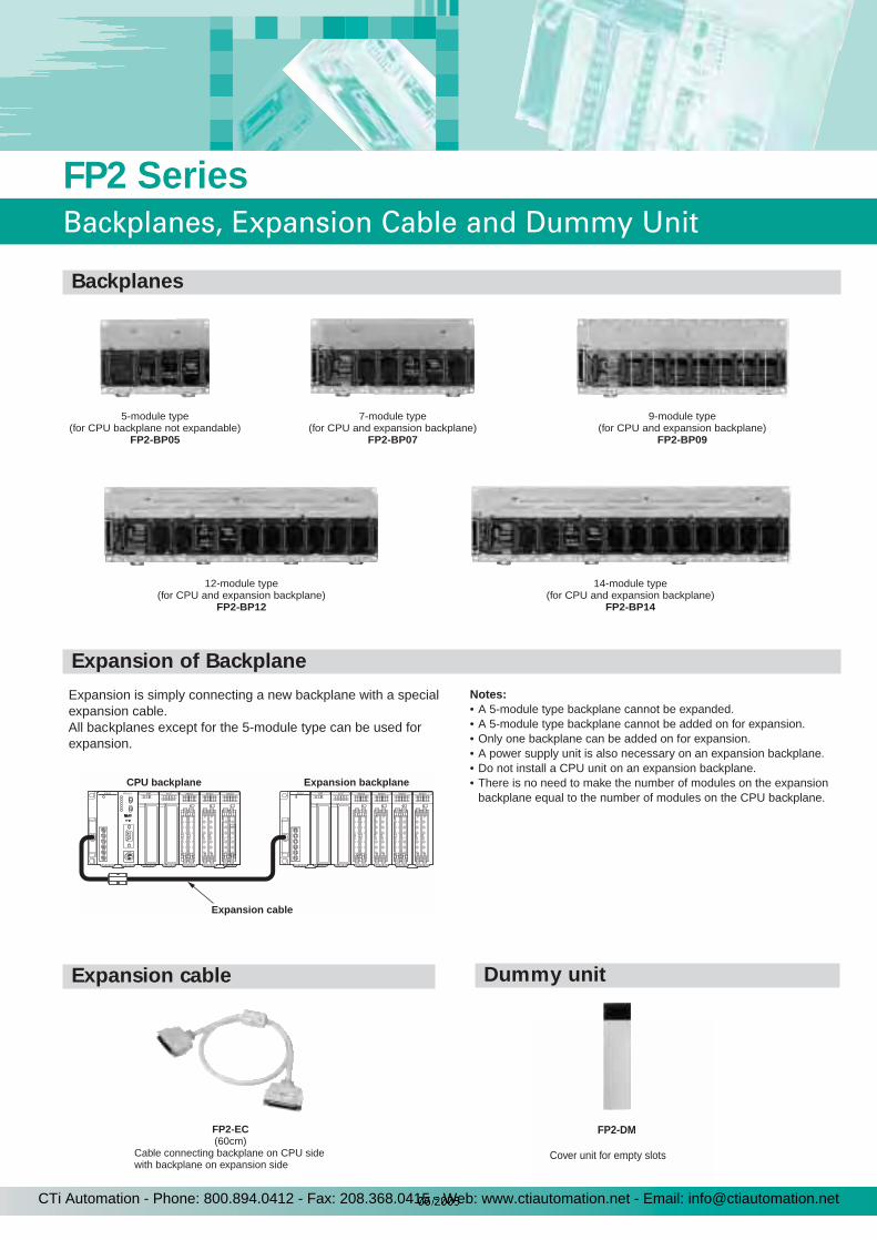
12-module type(for CPU and expansion backplane)
FP2-BP12
14-module type(for CPU and expansion backplane)
FP2-BP14
5-module type(for CPU backplane not expandable)
FP2-BP05
7-module type(for CPU and expansion backplane)
FP2-BP07
9-module type(for CPU and expansion backplane)
FP2-BP09
Expansion is simply connecting a new backplane with a special expansion cable. All backplanes except for the 5-module type can be used forexpansion.
Notes:• A 5-module type backplane cannot be expanded.• A 5-module type backplane cannot be added on for expansion.• Only one backplane can be added on for expansion.• A power supply unit is also necessary on an expansion backplane.• Do not install a CPU unit on an expansion backplane.• There is no need to make the number of modules on the expansion
backplane equal to the number of modules on the CPU backplane.CPU backplane Expansion backplane
Expansion cable
FP2-EC(60cm)
Cable connecting backplane on CPU sidewith backplane on expansion side
FP2-DM
Cover unit for empty slots
33
FP2 Series
Backplanes, Expansion Cable and Dummy Unit
Backplanes
Expansion of Backplane
Expansion cable Dummy unit
CTi Automation - Phone: 800.894.0412 - Fax: 208.368.0415 - Web: www.ctiautomation.net - Email: [email protected]
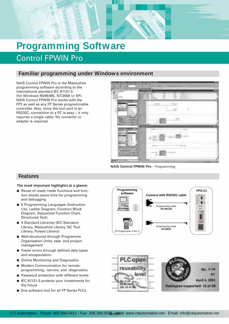
34
Programming Software
Control FPWIN Pro
NAiS Control FPWIN Pro is the Matsushitaprogramming software according to theinternational standard IEC 61131-3 (for Windows 95/98/ME, NT/2000 or XP).NAiS Control FPWIN Pro works with the FP2 as well as any FP Series programmablecontroller. Also, since the tool port is anRS232C, connection to a PC is easy – it onlyrequires a single cable. No converter oradapter is required.
FP Programmer II Ver. 2
Programming cableAFC8513D
Programming cableAFC8523
Programmingsoftware
Connect with RS232C cableFP2-C1
The most important highlights at a glance:
Reuse of ready made functions and func-tion blocks saves time for programmingand debugging
5 Programming Languages (InstructionList, Ladder Diagram, Function BlockDiagram, Sequential Function Chart,Structured Text)
4 Standard Libraries (IEC-StandardLibrary, Matsushita Library, NC ToolLibrary, Pulsed Library)
Well-structured through ProgrammeOrganisation Units, task- and project-management
Fewer errors through defined data types and encapsulation
Online Monitoring and Diagnostics
Modem Communication for remote-programming, -service, and -diagnostics
Password protection with different levels
IEC 61131-3 protects your investments forthe future
One software tool for all FP Series PLCs
NAiS Control FPWIN Pro – Programming
Familiar programming under Windows environment
Features
CTi Automation - Phone: 800.894.0412 - Fax: 208.368.0415 - Web: www.ctiautomation.net - Email: [email protected]
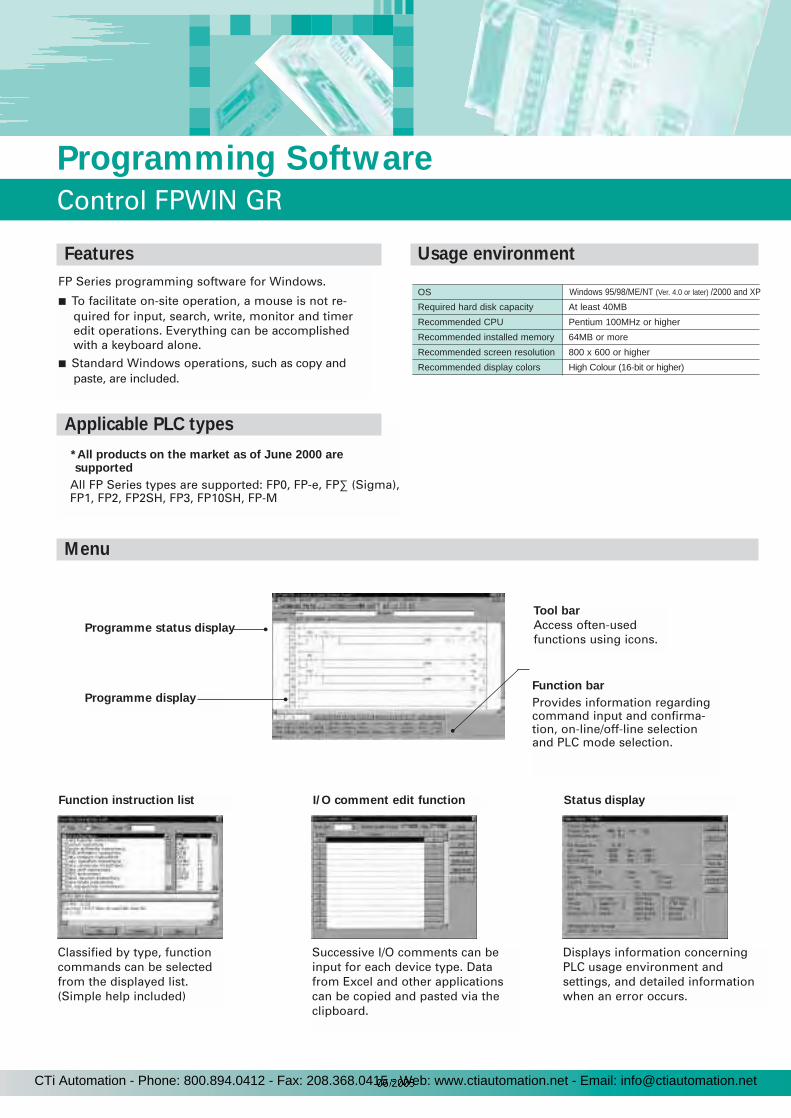
35
Programming Software
Control FPWIN GR
FP Series programming software for Windows.
To facilitate on-site operation, a mouse is not re-quired for input, search, write, monitor and timeredit operations. Everything can be accomplishedwith a keyboard alone.
Standard Windows operations, such as copy andpaste, are included.
Programme status display
Function instruction list
Classified by type, functioncommands can be selectedfrom the displayed list.(Simple help included)
*All products on the market as of June 2000 are supported
All FP Series types are supported: FP0, FP-e, FP∑ (Sigma),FP1, FP2, FP2SH, FP3, FP10SH, FP-M
OS
Required hard disk capacity
Recommended CPU
Recommended installed memory
Recommended screen resolution
Recommended display colors
Windows 95/98/ME/NT (Ver. 4.0 or later) /2000 and XP
At least 40MB
Pentium 100MHz or higher
64MB or more
800 x 600 or higher
High Colour (16-bit or higher)
Programme display
Tool bar
Access often-usedfunctions using icons.
Function bar
Provides information regardingcommand input and confirma-tion, on-line/off-line selectionand PLC mode selection.
I/O comment edit function
Successive I/O comments can beinput for each device type. Datafrom Excel and other applicationscan be copied and pasted via theclipboard.
Status display
Displays information concerningPLC usage environment andsettings, and detailed informationwhen an error occurs.
Features Usage environment
Applicable PLC types
Menu
CTi Automation - Phone: 800.894.0412 - Fax: 208.368.0415 - Web: www.ctiautomation.net - Email: [email protected]
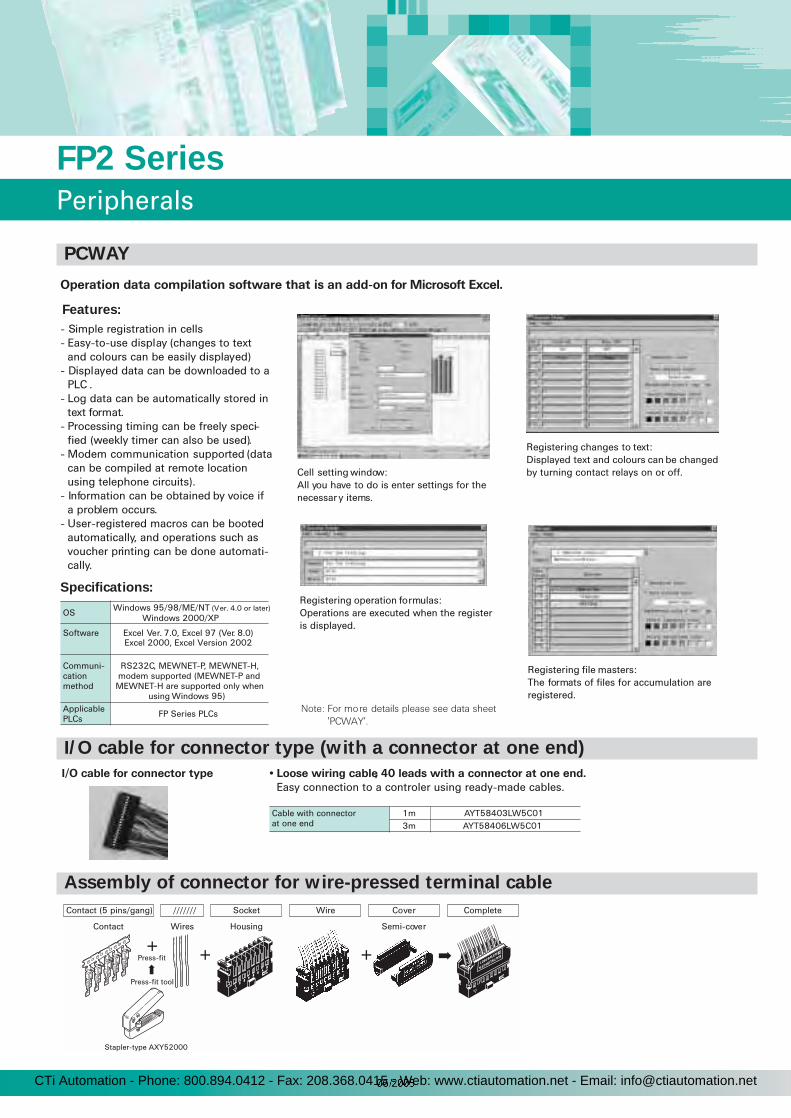
- Simple registration in cells- Easy-to-use display (changes to text
and colours can be easily displayed)- Displayed data can be downloaded to a
PLC .- Log data can be automatically stored in
text format.- Processing timing can be freely speci-
fied (weekly timer can also be used).- Modem communication supported (data
can be compiled at remote location using telephone circuits).
- Information can be obtained by voice if a problem occurs.
- User-registered macros can be booted automatically, and operations such as voucher printing can be done automati-cally.
OS Windows 95/98/ME/NT (Ver. 4.0 or later)
Software Excel Ver. 7.0, Excel 97 (Ver. 8.0)
Communi-cation method
RS232C, MEWNET-P, MEWNET-H, modem supported (MEWNET-P and MEWNET-H are supported only when
using Windows 95)ApplicablePLCs FP Series PLCs
Cell setting window: All you have to do is enter settings for the necessar y items.
Registering changes to text: Displayed text and colours can be changed by turning contact relays on or off..
Registering operation formulas: Operations are executed when the register is displayed.
Registering file masters: The formats of files for accumulation are registered.
Note: For more details please see data sheet
'PCWAY'.
Operation data compilation software that is an add-on for Microsoft Excel.
I/O cable for connector type • Loose wiring cable, 40 leads with a connector at one end.
Easy connection to a controler using ready-made cables.
Stapler-type AXY52000
Contact (5 pins/gang)
Contact
///////
Wires
+Press-fit
Press-fit tool
+ +
Socket
Housing
Wire Cover
Semi-cover
Complete
1122
3344
5566
7788
Cable with connectorat one end
1m AYT58403LW5C013m AYT58406LW5C01
Windows 2000/XP
Excel 2000, Excel Version 2002
FP2 Series
Peripherals
PCWAY
Features:
Specifications:
I/O cable for connector type (with a connector at one end)
Assembly of connector for wire-pressed terminal cable
CTi Automation - Phone: 800.894.0412 - Fax: 208.368.0415 - Web: www.ctiautomation.net - Email: [email protected]
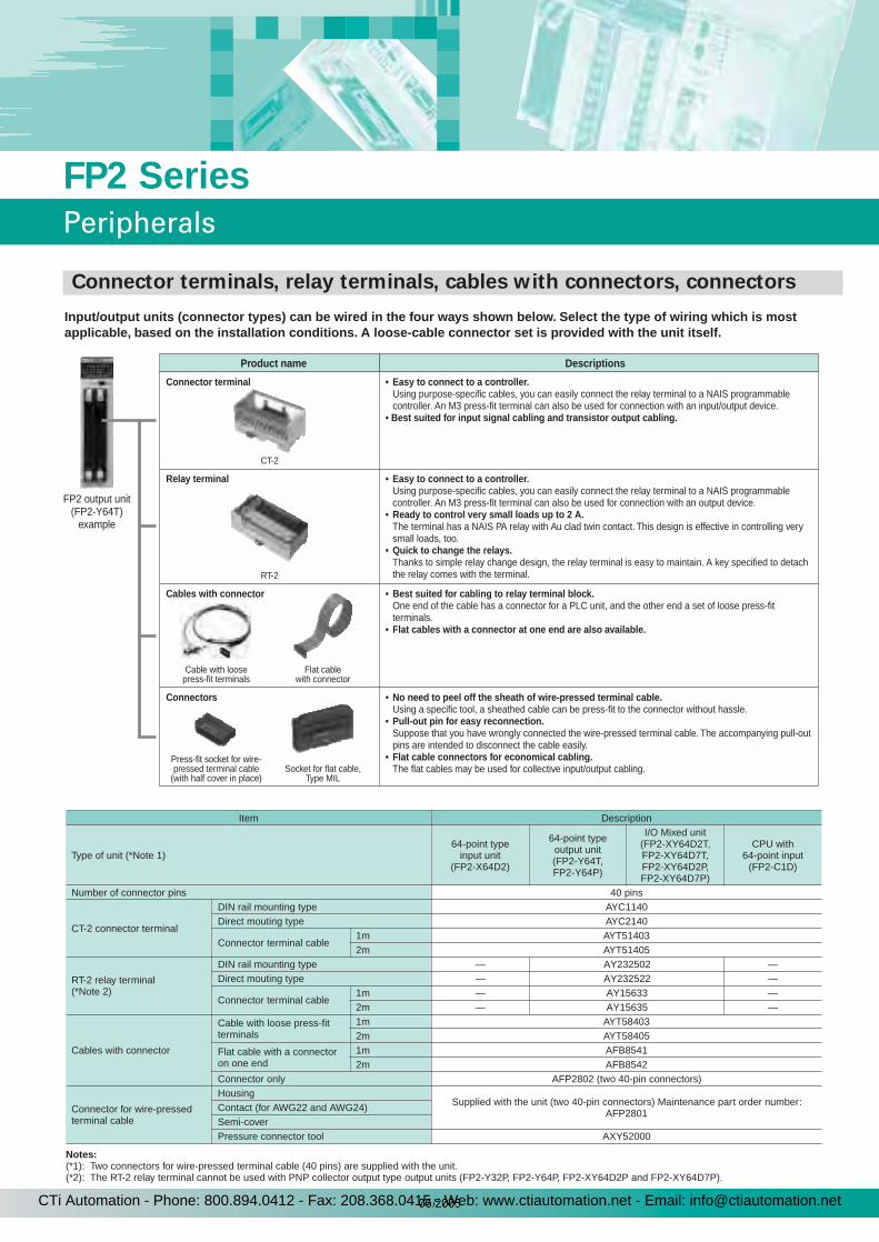
Notes:(*1): Two connectors for wire-pressed terminal cable (40 pins) are supplied with the unit.(*2): The RT-2 relay terminal cannot be used with PNP collector output type output units (FP2-Y32P, FP2-Y64P, FP2-XY64D2P and FP2-XY64D7P).
Item Description
Type of unit (*Note 1)64-point type
input unit (FP2-X64D2)
64-point type output unit (FP2-Y64T, FP2-Y64P)
I/O Mixed unit (FP2-XY64D2T, FP2-XY64D7T, FP2-XY64D2P, FP2-XY64D7P)
CPU with 64-point input
(FP2-C1D)
Number of connector pins 40 pins
CT-2 connector terminal
DIN rail mounting type AYC1140Direct mouting type AYC2140
Connector terminal cable1m AYT514032m AYT51405
RT-2 relay terminal (*Note 2)
DIN rail mounting type — AY232502 —Direct mouting type — AY232522 —
Connector terminal cable1m — AY15633 —2m — AY15635 —
Cables with connector
Cable with loose press-fit terminals
1m AYT584032m AYT58405
Flat cable with a connector on one end
1m AFB85412m AFB8542
Connector only AFP2802 (two 40-pin connectors)
Connector for wire-pressed terminal cable
HousingSupplied with the unit (two 40-pin connectors) Maintenance part order number:
AFP2801Contact (for AWG22 and AWG24)Semi-coverPressure connector tool AXY52000
Input/output units (connector types) can be wired in the four ways shown below. Select the type of wiring which is most applicable, based on the installation conditions. A loose-cable connector set is provided with the unit itself.
• Easy to connect to a controller.Using purpose-specific cables, you can easily connect the relay terminal to a NAIS programmable controller. An M3 press-fit terminal can also be used for connection with an input/output device.
• Best suited for input signal cabling and transistor output cabling.
• Easy to connect to a controller.Using purpose-specific cables, you can easily connect the relay terminal to a NAIS programmable controller. An M3 press-fit terminal can also be used for connection with an output device.
• Ready to control very small loads up to 2 A.The terminal has a NAIS PA relay with Au clad twin contact. This design is effective in controlling very small loads, too.
• Quick to change the relays.Thanks to simple relay change design, the relay terminal is easy to maintain. A key specified to detach the relay comes with the terminal.
• Best suited for cabling to relay terminal block.One end of the cable has a connector for a PLC unit, and the other end a set of loose press-fit terminals.
• Flat cables with a connector at one end are also available.
• No need to peel off the sheath of wire-pressed terminal cable.Using a specific tool, a sheathed cable can be press-fit to the connector without hassle.
• Pull-out pin for easy reconnection.Suppose that you have wrongly connected the wire-pressed terminal cable. The accompanying pull-out pins are intended to disconnect the cable easily.
• Flat cable connectors for economical cabling.The flat cables may be used for collective input/output cabling.
FP2 output unit(FP2-Y64T)
example
Product name Descriptions
Connector terminal
Relay terminal
Cables with connector
Cable with loosepress-fit terminals
CT-2
RT-2
Flat cablewith connector
Press-fit socket for wire-pressed terminal cable
(with half cover in place)Socket for flat cable,
Type MIL
Connectors
37
FP2 Series
Peripherals
Connector terminals, relay terminals, cables with connectors, connectors
CTi Automation - Phone: 800.894.0412 - Fax: 208.368.0415 - Web: www.ctiautomation.net - Email: [email protected]

Product name Description Part number
FP2 CPU unit
Standard type CPU unit FP2-C1CPU unit with 64-point input FP2-C1DCPU unit with analogue I/O FP2-C1A
CPU unit with S-LINK interfaces FP2-C1SL
Product name Description Part number
Backplane
5-module type (for master) FP2-BP05 7-module type (for master and expansion) FP2-BP07 9-module type (for master and expansion) FP2-BP0912-module type (for master and expansion) FP2-BP1214-module type (for master and expansion) FP2-BP14
Expansion cable 60cm FP2-ECDummy unit Cover unit for empty modules FP2-DM
Product name Description Part number
Power supply unit
100VAC 2.5A type FP2-PSA1200VAC 2.5A type FP2-PSA2
100 to 240VAC 5A type FP2-PSA324VDC 5A type FP2-PSD2
Product name Type (Number of I/O point) Style Specification Part number
Input unit16-point DC input Terminal type 12 to 24VDC, sink/source input FP2-X16D232-point DC input Connector type 24VDC, sink/source input FP2-X32D264-point DC input Connector type 24VDC, sink/source input FP2-X64D2
Output unit
16-point, transistor output (NPN) Terminal type 5 to 24VDC, 0.5A FP2-Y16T32-point transistor output (NPN) Connector type 5 to 24VDC, 0.1A FP2-Y32T64-point, transistor output (NPN) Connector type 5 to 24VDC, 0.1A FP2-Y64T16-point, transistor output (PNP) Terminal type 5 to 24VDC, 0.5A FP2-Y16P32-point transistor output (PNP) Connector type 5 to 24VDC, 0.1A FP2-Y32P64-point, transistor output (PNP) Connector type 5 to 24VDC, 0.1A FP2-Y64P
6-point, relay output Terminal type 5A 250VAC, 5A 30VDC without relay socket FP2-Y6R16-point, relay output Terminal type 2A 250VAC, 2A 30VDC without relay socket FP2-Y16R
I/O mixed unit
32 input points/32 output points (NPN) Connector type Input: 24VDC, Output: 0.1A (at 12 to 24VDC) FP2-XY64D2T32 input points/32 output points (PNP) Connector type Input: 24VDC, Output: 0.1A (at 12 to 24VDC) FP2-XY64D2P32 input points/32 output points (NPN)
with ON pulse catch input Connector type Input: 24VDC, Output: 0.1A (at 12 to 24VDC) FP2-XY64D7T
32 input points/32 output points (PNP) with ON pulse catch input Connector type Input: 24VDC, Output: 0.1A (at 12 to 24VDC) FP2-XY64D7P
Product name Description Part number
Expansion memory unit
Comment input and calendar FP2-EM1
Expansion RAM, comment input and calendar FP2-EM2ROM socket, expansion RAM, comment input and calendar FP2-EM3
ROM socket and expansion RAM FP2-EM6ROM socket FP2-EM7
ROMFROM FP2-EM4
EPROM FP2-EM5
FP2SH CPU unit
Standard type CPU unit, 60k stepsCPU unit, 60k steps, with IC card interfaceCPU unit, 120k steps, with IC card interface
FP2-C2FP2-C2PFP2-C3P
IC memory card2MB SRAM type for FP2SH CPUs
2MB FROM type for FP2SH CPUs
AIC 52000AIC 50020
DIN rail power supply 100 to 240VAC 2.1A type; 24VDC output FP-PS24-050E
FP2 Series
Product Types
CPU unit
Optional memory
Backplane / expansion cable / dummy unit
Power supply unit
I/O unit
CTi Automation - Phone: 800.894.0412 - Fax: 208.368.0415 - Web: www.ctiautomation.net - Email: [email protected]
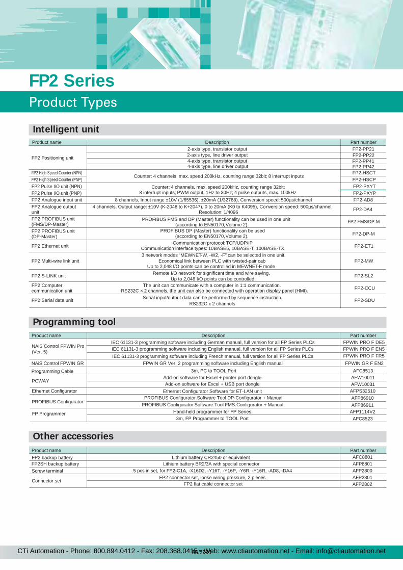
Product name Description Part number
IEC 61131-3 programming software including German manual, full version for all FP Series PLCs FPWIN PRO F DE5
FPWIN PRO F EN5
FPWIN GR Ver. 2 programming software including English manual FPWIN GR F EN2
Add-on software for Excel + printer port dongle AFW10011PCWAY
AFW10031
Product name Description Part number
FP2 Positioning unit
2-axis type, transistor output FP2-PP21
4-axis type, line driver output FP2-PP42FP2 High Speed Counter (NPN)
Counter: 4 channels max. speed 200kHz, counting range 32bit; 8 interrupt inputsFP2-HSCT
FP2 High Speed Counter (PNP) FP2-HSCPFP2 Pulse I/O unit (NPN) Counter: 4 channels, max. speed 200kHz, counting range 32bit;
8 interrupt inputs; PWM output, 1Hz to 30Hz; 4 pulse outputs, max. 100kHzFP2-PXYT
FP2 Pulse I/O unit (PNP) FP2-PXYPFP2 Analogue input unit 8 channels, Input range ±10V (1/65536), ±20mA (1/32768), Conversion speed: 500µs/channel FP2-AD8FP2 Analogue output unit
4 channels, Output range: ±10V (K-2048 to K+2047), 0 to 20mA (K0 to K4095), Conversion speed: 500µs/channel, Resolution: 1/4096 FP2-DA4
FP2 PROFIBUS unit (FMS/DP-Master)
PROFIBUS FMS and DP (Master) functionality can be used in one unit(according to EN50170, Volume 2).
FP2-FMS/DP-M
FP2 PROFIBUS unit(DP-Master)
PROFIBUS DP (Master) functionality can be used (according to EN50170, Volume 2). FP2-DP-M
FP2 Ethernet unitCommunication protocol: TCP/UDP/IP
Communication interface types: 10BASE5, 10BASE-T, 100BASE-TX FP2-ET1
FP2 Multi-wire link unit3 network modes “MEWNET-W, -W2, -F” can be selected in one unit.
Economical link between PLC with twisted-pair cab.Up to 2,048 I/O points can be controlled in MEWNET-F mode.
FP2-MW
FP2 S-LINK unit Remote I/O network for significant time and wire saving.Up to 2,048 I/O points can be controlled.
FP2-SL2
FP2 Computer communication unit
The unit can communicate with a computer in 1:1 communication.RS232C × 2 channels, the unit can also be connected with operation display panel (HMI). FP2-CCU
FP2 Serial data unit Serial input/output data can be performed by sequence instruction.RS232C x 2 channels
FP2-SDU
2-axis type, line driver output4-axis type, transistor output
FP2-PP22FP2-PP41
NAiS Control FPWIN Pro(Ver. 5)
NAiS Control FPWIN GR
Add-on software for Excel + USB port dongle
FP Programmer Hand-held programmer for FP Series3m, FP Programmer to TOOL Port
AFP1114V2
AFC8523
Product name Description Part number
Lithium battery CR2450 or equivalent AFC8801
Lithium battery BR2/3A with special connector AFP8801 5 pcs in set, for FP2-C1A, -X16D2, -Y16T, -Y16P, -Y6R, -Y16R, -AD8, -DA4 AFP2800
FP2 connector set, loose wiring pressure, 2 pieces AFP2801Connector set
AFP2802
FP2 backup batteryFP2SH backup battery
FP2 flat cable connector set
Screw terminal
IEC 61131-3 programming software including English manual, full version for all FP Series PLCs
IEC 61131-3 programming software including French manual, full version for all FP Series PLCs FPWIN PRO F FR5
Ethernet Configurator
PROFIBUS Configurator
Ethernet Configurator Software for ET-LAN unit AFPS32510PROFIBUS Configurator Software Tool DP-Configurator + Manual
PROFIBUS Configurator Software Tool FMS-Configurator + ManualAFP86910
AFP86911
Programming Cable 3m, PC to TOOL Port AFC8513
39
FP2 Series
Product Types
Intelligent unit
Programming tool
Other accessories
CTi Automation - Phone: 800.894.0412 - Fax: 208.368.0415 - Web: www.ctiautomation.net - Email: [email protected]