NAFFCO - UL Listed Fire Pump
12
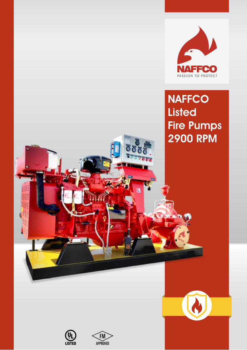
NAFFCO Listed Fire Pumps 2900 RPM
-
Upload
naffco-fzco -
Category
Engineering
-
view
956 -
download
96
Transcript of NAFFCO - UL Listed Fire Pump
1-1/2” BS 336 male
NAFFCOListedFire Pumps2900 RPM
www.naffco.com2
NAFFCO FZCO is among the world’s leading manufacturers and suppliers of top-tier firefighting equipment, fire protection systems, fire alarms, security and safety engineering systems worldwide. Since its humble beginnings, NAFFCO has grown from its headquarters in Dubai, UAE to expand to serving over 100 countries around the world.
One Stop Shopping for All Your Fire Safety and Security Needs
Today’s companies recognize the importance and convenience of having multiple safety services available under one roof, a “one-stop shopping” source for all types of fire protection systems. As the undisputed leader in
An Introduction to NAFFCO
firefighting technology and fire safety solutions, NAFFCO has worked in both the private and government sectors, as well as manufacturing plants, hospitals, stadiums, malls and other organizational projects, delivering comprehensive fire safety and engineering solutions.
NAFFCO is associated with globally renowned international companies in the fire protection industry such as Esser, Secutron, Megalights, Evax, Fike, Central, Shield, Mueller, Giacomini, RB Pumps, Bombas, Ideal Pumps, Joslyn Pumps, Peerless Pumps.
At NAFFCO we are passionate about sustaining, upgrading and improving any means of safety, by having over 2 million square foot of manufacturing space, over 450 engineers, and following all the latest technology available. We live by our passion, the passion to protect.
www.naffco.com 3
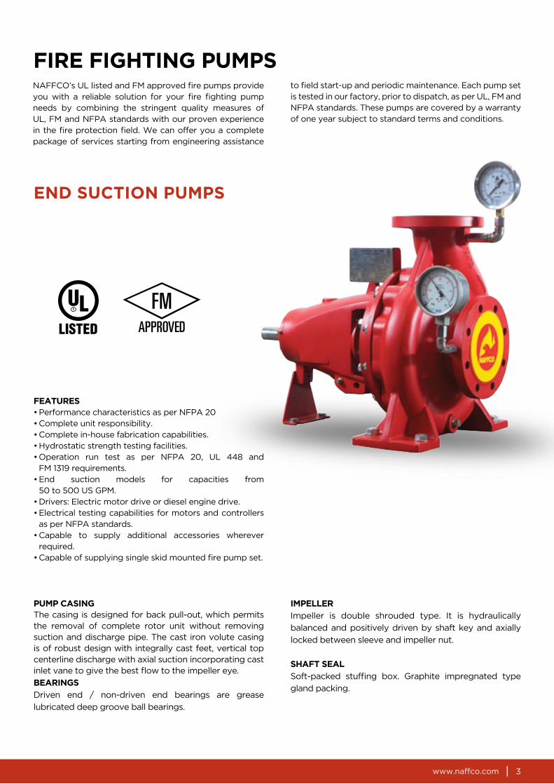
FIRE FIGHTING PUMPSNAFFCO’s UL listed and FM approved fire pumps provide you with a reliable solution for your fire fighting pump needs by combining the stringent quality measures of UL, FM and NFPA standards with our proven experience in the fire protection field. We can offer you a complete package of services starting from engineering assistance
PUMP CASINGThe casing is designed for back pull-out, which permits the removal of complete rotor unit without removing suction and discharge pipe. The cast iron volute casing is of robust design with integrally cast feet, vertical top centerline discharge with axial suction incorporating cast inlet vane to give the best flow to the impeller eye.
BEARINGS
Driven end / non-driven end bearings are grease
lubricated deep groove ball bearings.
to field start-up and periodic maintenance. Each pump set is tested in our factory, prior to dispatch, as per UL, FM and NFPA standards. These pumps are covered by a warranty of one year subject to standard terms and conditions.
IMPELLER
Impeller is double shrouded type. It is hydraulically
balanced and positively driven by shaft key and axially
locked between sleeve and impeller nut.
SHAFT SEAL
Soft-packed stuffing box. Graphite impregnated type
gland packing.
END SUCTION PUMPS
FEATURES• Performance characteristics as per NFPA 20• Complete unit responsibility.• Complete in-house fabrication capabilities.• Hydrostatic strength testing facilities.• Operation run test as per NFPA 20, UL 448 and
FM 1319 requirements.• End suction models for capacities from
50 to 500 US GPM.• Drivers: Electric motor drive or diesel engine drive.• Electrical testing capabilities for motors and controllers
as per NFPA standards.• Capable to supply additional accessories wherever
required.• Capable of supplying single skid mounted fire pump set.
www.naffco.com4
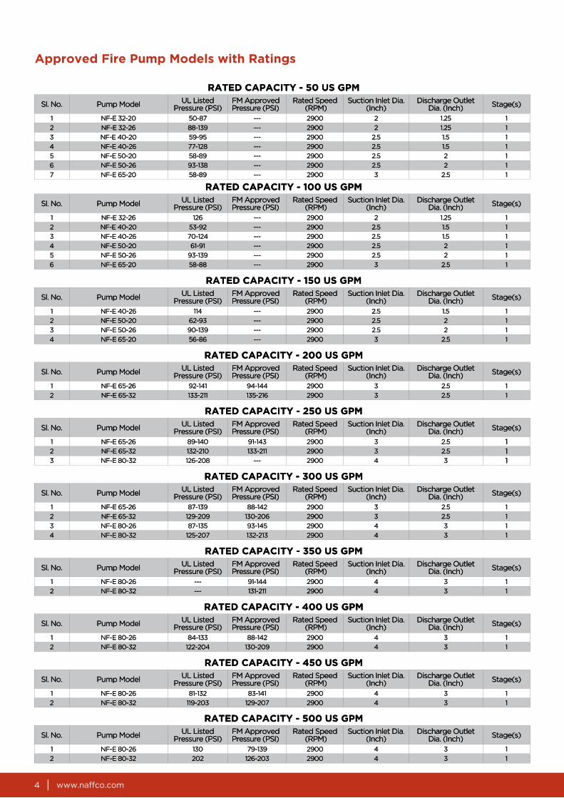
Approved Fire Pump Models with Ratings
RATED CAPACITY - 50 US GPM
Sl. No. Pump Model UL ListedPressure (PSI)
FM ApprovedPressure (PSI)
Rated Speed (RPM)
Suction Inlet Dia. (Inch)
Discharge Outlet Dia. (Inch) Stage(s)
1 NF-E 32-20 50-87 --- 2900 2 1.25 1
2 NF-E 32-26 88-139 --- 2900 2 1.25 1
3 NF-E 40-20 59-95 --- 2900 2.5 1.5 1
4 NF-E 40-26 77-128 --- 2900 2.5 1.5 1
5 NF-E 50-20 58-89 --- 2900 2.5 2 1
6 NF-E 50-26 93-138 --- 2900 2.5 2 1
7 NF-E 65-20 58-89 --- 2900 3 2.5 1
RATED CAPACITY - 100 US GPM
Sl. No. Pump Model UL ListedPressure (PSI)
FM ApprovedPressure (PSI)
Rated Speed (RPM)
Suction Inlet Dia. (Inch)
Discharge Outlet Dia. (Inch) Stage(s)
1 NF-E 32-26 126 --- 2900 2 1.25 1
2 NF-E 40-20 53-92 --- 2900 2.5 1.5 1
3 NF-E 40-26 70-124 --- 2900 2.5 1.5 1
4 NF-E 50-20 61-91 --- 2900 2.5 2 1
5 NF-E 50-26 93-139 --- 2900 2.5 2 1
6 NF-E 65-20 58-88 --- 2900 3 2.5 1
RATED CAPACITY - 200 US GPM
Sl. No. Pump Model UL ListedPressure (PSI)
FM ApprovedPressure (PSI)
Rated Speed (RPM)
Suction Inlet Dia. (Inch)
Discharge Outlet Dia. (Inch) Stage(s)
1 NF-E 65-26 92-141 94-144 2900 3 2.5 1
2 NF-E 65-32 133-211 135-216 2900 3 2.5 1
RATED CAPACITY - 350 US GPM
Sl. No. Pump Model UL ListedPressure (PSI)
FM ApprovedPressure (PSI)
Rated Speed (RPM)
Suction Inlet Dia. (Inch)
Discharge Outlet Dia. (Inch) Stage(s)
1 NF-E 80-26 --- 91-144 2900 4 3 1
2 NF-E 80-32 --- 131-211 2900 4 3 1
RATED CAPACITY - 400 US GPM
Sl. No. Pump Model UL ListedPressure (PSI)
FM ApprovedPressure (PSI)
Rated Speed (RPM)
Suction Inlet Dia. (Inch)
Discharge Outlet Dia. (Inch) Stage(s)
1 NF-E 80-26 84-133 88-142 2900 4 3 1
2 NF-E 80-32 122-204 130-209 2900 4 3 1
RATED CAPACITY - 250 US GPM
Sl. No. Pump Model UL ListedPressure (PSI)
FM ApprovedPressure (PSI)
Rated Speed (RPM)
Suction Inlet Dia. (Inch)
Discharge Outlet Dia. (Inch) Stage(s)
1 NF-E 65-26 89-140 91-143 2900 3 2.5 12 NF-E 65-32 132-210 133-211 2900 3 2.5 13 NF-E 80-32 126-208 --- 2900 4 3 1
RATED CAPACITY - 300 US GPM
Sl. No. Pump Model UL ListedPressure (PSI)
FM ApprovedPressure (PSI)
Rated Speed (RPM)
Suction Inlet Dia. (Inch)
Discharge Outlet Dia. (Inch) Stage(s)
1 NF-E 65-26 87-139 88-142 2900 3 2.5 1
2 NF-E 65-32 129-209 130-206 2900 3 2.5 1
3 NF-E 80-26 87-135 93-145 2900 4 3 1
4 NF-E 80-32 125-207 132-213 2900 4 3 1
RATED CAPACITY - 150 US GPM
Sl. No. Pump Model UL ListedPressure (PSI)
FM ApprovedPressure (PSI)
Rated Speed (RPM)
Suction Inlet Dia. (Inch)
Discharge Outlet Dia. (Inch) Stage(s)
1 NF-E 40-26 114 --- 2900 2.5 1.5 1
2 NF-E 50-20 62-93 --- 2900 2.5 2 1
3 NF-E 50-26 90-139 --- 2900 2.5 2 1
4 NF-E 65-20 56-86 --- 2900 3 2.5 1
RATED CAPACITY - 450 US GPM
Sl. No. Pump Model UL ListedPressure (PSI)
FM ApprovedPressure (PSI)
Rated Speed (RPM)
Suction Inlet Dia. (Inch)
Discharge Outlet Dia. (Inch) Stage(s)
1 NF-E 80-26 81-132 83-141 2900 4 3 1
2 NF-E 80-32 119-203 129-207 2900 4 3 1
RATED CAPACITY - 500 US GPM
Sl. No. Pump Model UL ListedPressure (PSI)
FM ApprovedPressure (PSI)
Rated Speed (RPM)
Suction Inlet Dia. (Inch)
Discharge Outlet Dia. (Inch) Stage(s)
1 NF-E 80-26 130 79-139 2900 4 3 1
2 NF-E 80-32 202 126-203 2900 4 3 1

www.naffco.com 5
CUT-SECTIONAL VIEW
DESCRIPTION
No. Part Name Material Qty.
1 Casing Cast Iron ASTM A48 Class 40 1
2 Impeller Bronze SAE 40 1
3 Wear ring Bronze SAE 40 1
4 Stuffing Box (Casing Cover) Cast Iron ASTM A48 Class 40 1
5 Gland Packing Graphite Impregnated 4
6 Gland Bronze SAE 40 1
7 Lantern Ring Bronze SAE 40 1
8 Bearing Housing Cast Iron ASTM A48 Class 40 1
9 Shaft Stainless Steel AISI 420 1
10 Shaft Sleeve Stainless Steel AISI 420 1
11 Bearing Bearing Steel 2
12 Foot Support Steel 1
13 “O” Ring Buna N Rubber 1
14 Coupling Key Stainless Steel AISI 420 1
www.naffco.com6
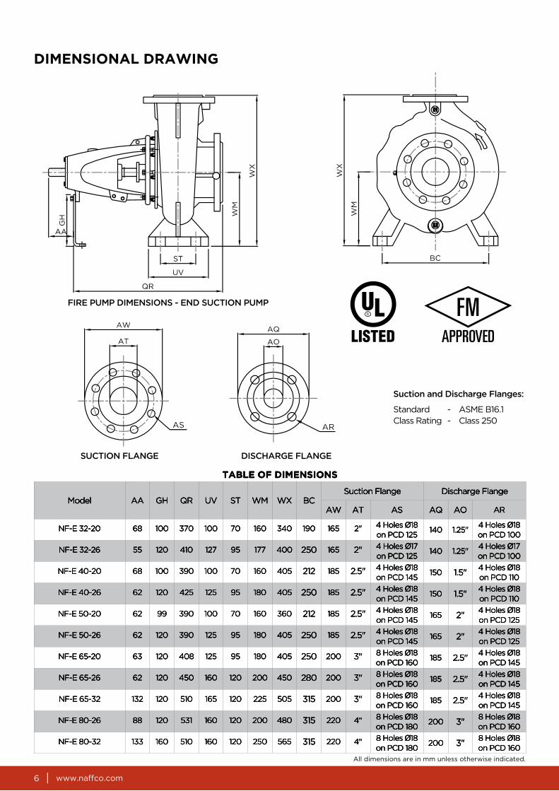
DIMENSIONAL DRAWING
TABLE OF DIMENSIONS
Model AA GH QR UV ST WM WX BCSuction Flange Discharge Flange
AW AT AS AQ AO AR
NF-E 32-20 68 100 370 100 70 160 340 190 165 2" 4 Holes Ø18 on PCD 125
140 1.25"4 Holes Ø18 on PCD 100
NF-E 32-26 55 120 410 127 95 177 400 250 165 2" 4 Holes Ø17 on PCD 125
140 1.25"4 Holes Ø17 on PCD 100
NF-E 40-20 68 100 390 100 70 160 405 212 185 2.5" 4 Holes Ø18 on PCD 145
150 1.5"4 Holes Ø18 on PCD 110
NF-E 40-26 62 120 425 125 95 180 405 250 185 2.5" 4 Holes Ø18 on PCD 145
150 1.5"4 Holes Ø18 on PCD 110
NF-E 50-20 62 99 390 100 70 160 360 212 185 2.5" 4 Holes Ø18 on PCD 145
165 2"4 Holes Ø18 on PCD 125
NF-E 50-26 62 120 390 125 95 180 405 250 185 2.5" 4 Holes Ø18 on PCD 145
165 2"4 Holes Ø18 on PCD 125
NF-E 65-20 63 120 408 125 95 180 405 250 200 3" 8 Holes Ø18 on PCD 160
185 2.5"4 Holes Ø18 on PCD 145
NF-E 65-26 62 120 450 160 120 200 450 280 200 3" 8 Holes Ø18 on PCD 160
185 2.5"4 Holes Ø18 on PCD 145
NF-E 65-32 132 120 510 165 120 225 505 315 200 3" 8 Holes Ø18 on PCD 160
185 2.5"4 Holes Ø18 on PCD 145
NF-E 80-26 88 120 531 160 120 200 480 315 220 4" 8 Holes Ø18 on PCD 180
200 3"8 Holes Ø18 on PCD 160
NF-E 80-32 133 160 510 160 120 250 565 315 220 4" 8 Holes Ø18 on PCD 180
200 3"8 Holes Ø18 on PCD 160
ASME B16.1Class 250
Standard Class Rating
--
www.naffco.com 7
Approved Fire Pump Models with Ratings
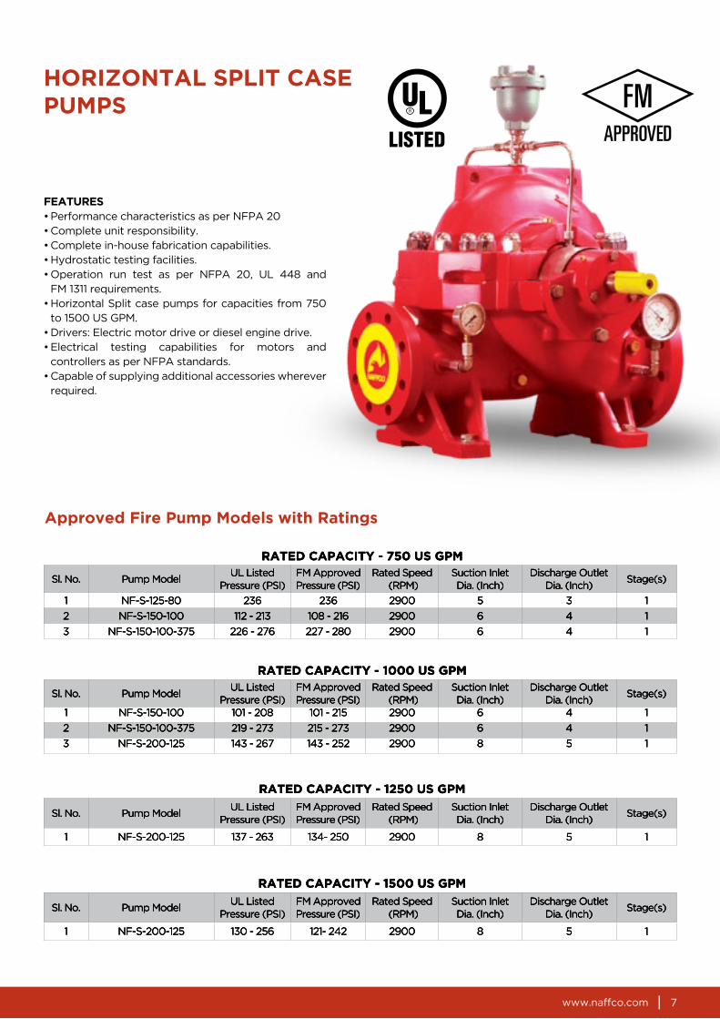
HORIZONTAL SPLIT CASE PUMPS
FEATURES• Performance characteristics as per NFPA 20• Complete unit responsibility.• Complete in-house fabrication capabilities.• Hydrostatic testing facilities.• Operation run test as per NFPA 20, UL 448 and
FM 1311 requirements.• Horizontal Split case pumps for capacities from 750
to 1500 US GPM.• Drivers: Electric motor drive or diesel engine drive.• Electrical testing capabilities for motors and
controllers as per NFPA standards.• Capable of supplying additional accessories wherever
required.
RATED CAPACITY - 750 US GPM
Sl. No. Pump ModelUL Listed
Pressure (PSI)FM ApprovedPressure (PSI)
Rated Speed (RPM)
Suction Inlet Dia. (Inch)
Discharge Outlet Dia. (Inch)
Stage(s)
1 NF-S-125-80 236 236 2900 5 3 1
2 NF-S-150-100 112 - 213 108 - 216 2900 6 4 1
3 NF-S-150-100-375 226 - 276 227 - 280 2900 6 4 1
RATED CAPACITY - 1000 US GPM
Sl. No. Pump ModelUL Listed
Pressure (PSI)FM ApprovedPressure (PSI)
Rated Speed (RPM)
Suction Inlet Dia. (Inch)
Discharge Outlet Dia. (Inch)
Stage(s)
1 NF-S-150-100 101 - 208 101 - 215 2900 6 4 1
2 NF-S-150-100-375 219 - 273 215 - 273 2900 6 4 1
3 NF-S-200-125 143 - 267 143 - 252 2900 8 5 1
RATED CAPACITY - 1250 US GPM
Sl. No. Pump ModelUL Listed
Pressure (PSI)FM ApprovedPressure (PSI)
Rated Speed (RPM)
Suction Inlet Dia. (Inch)
Discharge Outlet Dia. (Inch)
Stage(s)
1 NF-S-200-125 137 - 263 134- 250 2900 8 5 1
RATED CAPACITY - 1500 US GPM
Sl. No. Pump ModelUL Listed
Pressure (PSI)FM ApprovedPressure (PSI)
Rated Speed (RPM)
Suction Inlet Dia. (Inch)
Discharge Outlet Dia. (Inch)
Stage(s)
1 NF-S-200-125 130 - 256 121- 242 2900 8 5 1
www.naffco.com8
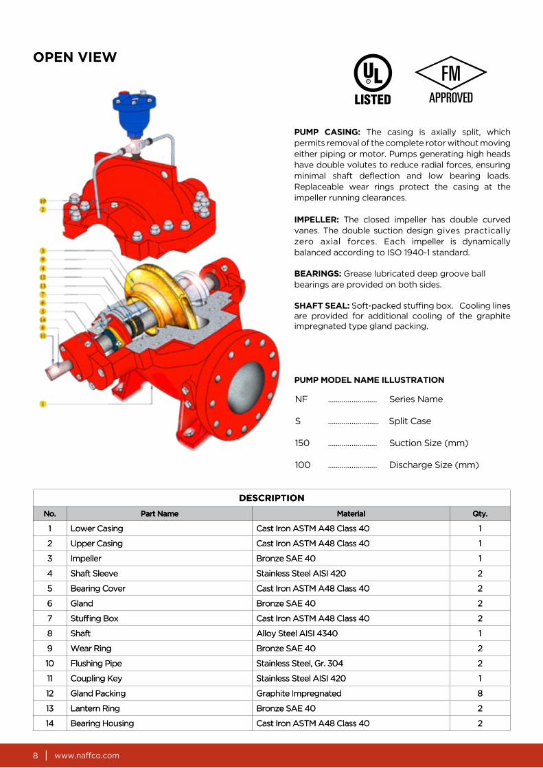
OPEN VIEW
PUMP CASING: The casing is axially split, which permits removal of the complete rotor without moving either piping or motor. Pumps generating high heads have double volutes to reduce radial forces, ensuring minimal shaft deflection and low bearing loads. Replaceable wear rings protect the casing at the impeller running clearances.
IMPELLER: The closed impeller has double curved vanes. The double suction design gives practically zero axial forces. Each impeller is dynamically balanced according to ISO 1940-1 standard.
BEARINGS: Grease lubricated deep groove ballbearings are provided on both sides.
SHAFT SEAL: Soft-packed stuffing box. Cooling lines are provided for additional cooling of the graphite impregnated type gland packing.
NF ......................... Series Name
S .......................... Split Case
150 ......................... Suction Size (mm)
100 ......................... Discharge Size (mm)
PUMP MODEL NAME ILLUSTRATION
DESCRIPTION
No. Part Name Material Qty.
1 Lower Casing Cast Iron ASTM A48 Class 40 1
2 Upper Casing Cast Iron ASTM A48 Class 40 1
3 Impeller Bronze SAE 40 1
4 Shaft Sleeve Stainless Steel AISI 420 2
5 Bearing Cover Cast Iron ASTM A48 Class 40 2
6 Gland Bronze SAE 40 2
7 Stuffing Box Cast Iron ASTM A48 Class 40 2
8 Shaft Alloy Steel AISI 4340 1
9 Wear Ring Bronze SAE 40 2
10 Flushing Pipe Stainless Steel, Gr. 304 2
11 Coupling Key Stainless Steel AISI 420 1
12 Gland Packing Graphite Impregnated 8
13 Lantern Ring Bronze SAE 40 2
14 Bearing Housing Cast Iron ASTM A48 Class 40 2

www.naffco.com 9
DIMENSIONAL DRAWING
NF ......................... Series Name
S .......................... Split Case
150 ......................... Suction Size (mm)
100 ......................... Discharge Size (mm)
ASME B16.1Class 250
Standard Class Rating
--
TABLE OF DIMENSIONS
Model AA AB AC AD AE B A BBSuction Flange Discharge Flange
AW AT AS AQ AO AR
NF-S-125-80 330 330 340 306 315 270 175 280 5"8 holes Ø22
on PCD 235 210 3"
8 holes Ø22
on PCD 168
NF-S-150-100 330 330 400 267 355 270 185 320 6"12 holes Ø22
on PCD 270255 4"
8 holes Ø22
on PCD 200
NF-S-150-100-375 375 375 400 340 355 270 185 320 6"12 holes Ø22
on PCD 270255 4"
8 holes Ø22
on PCD 200
NF-S-200-125 395 370 450 367 400 340 200 380 8"12 holes Ø28
on PCD 330280 5"
8 holes Ø22
on PCD 235

www.naffco.com10
GE
NE
RA
L A
RR
AN
GE
ME
NT
DR
AW
ING
F
OR
FIR
E P
UM
PS
No
.D
esc
rip
tio
n
1Suct
ion P
ress
ure
Gau
ge
2D
isch
arg
e P
ress
ure
Gau
ge
3C
asin
g R
elie
f V
alve
(E
lect
ric
Pum
p)
4A
uto
mat
ic A
ir R
ele
ase V
alve
5N
RV
with 3
/32”
Hole
6B
all V
alve
(Thre
aded
)
www.naffco.com 11
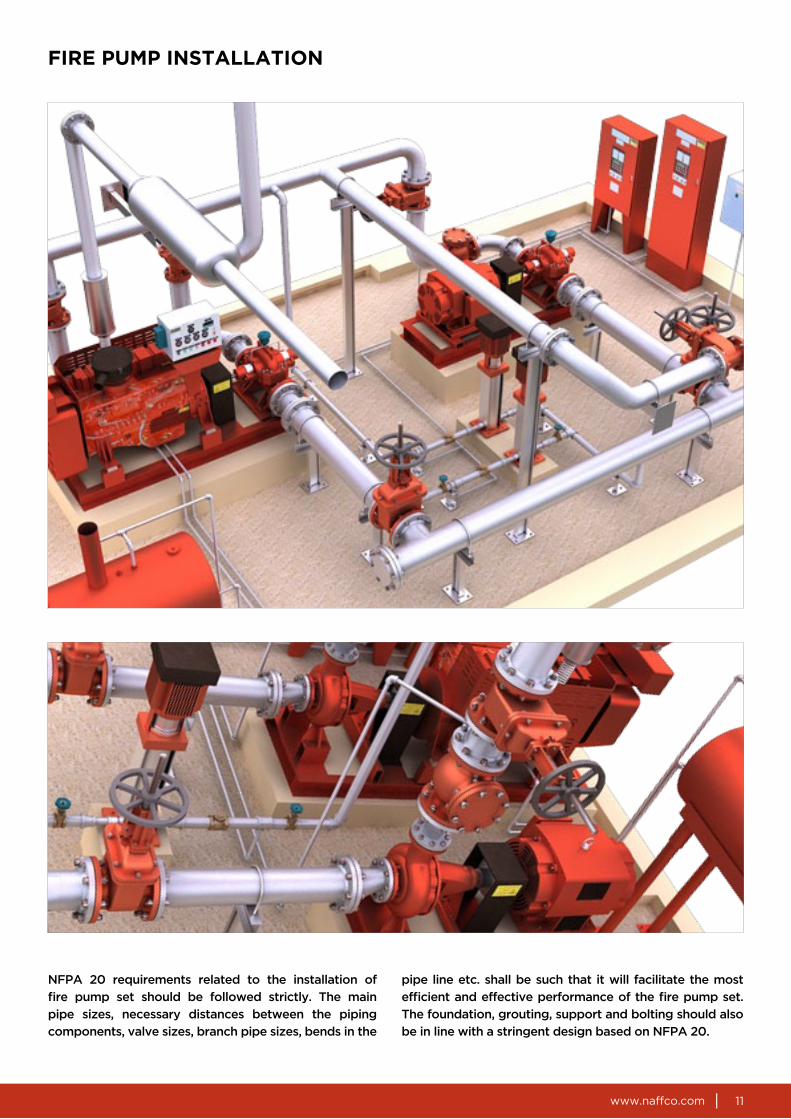
FIRE PUMP INSTALLATION

CAT
.NO
.NF/
ULFP
2900
/01/
15
In line with NAFFCO policy for continuous product development,NAFFCO has the right to change specifications without prior notice.
NAFFCO FZCOWorld HeadquartersDubai, United Arab EmiratesEmail: [email protected]
Serving Over 100 Countries WorldwideeeedededewidewidewidwiddwiddwidwldwrldwrldorldorldWorlWorWorWoWoWos Ws Wes Wes Wes iesriestrietrientrientrintruntuntounounounouCouCoCoCoCoCC0 C0 C00000000011