MV Switchgear for Substation Solutions .0...
40
www.ormazabal.com MV Switchgear for Substation Solutions cpg.0 & cpg.1 Single and double busbar panel type GIS system Up to 40.5 kV IEC Standards Up to 38 kV IEEE Standards Reliable innovation. Personal solutions.
Transcript of MV Switchgear for Substation Solutions .0...

www.ormazabal.com
MV Switchgear for
Substation Solutions
cpg.0 & cpg.1Single and double busbar panel type GIS system
Up to 40.5 kV IEC Standards Up to 38 kV IEEE Standards
Reliable innovation. Personal solutions.

cpg.0 & cpg.1 Single and double busbar panel type GIS system
MV Switchgear for Substation Solutions
The quality of the products designed, manufactured and installed by Ormazabal is backed by the implementation and certification of a quality management system, based on international standard ISO 9001:2008.Our commitment to the environment is reaffirmed with the implementation and certification of an environmental management system as laid down in international standard ISO 14001.In view of the constant evolution in standards and design, the characteristics of the elements contained in this catalogue are subject to change without prior notification.These characteristics, as well as the availability of components, are subject to confirmation by Ormazabal.
Contents
IntroduCtIon _________________________ 1Preface 1
Your Electrical Network 2
Your Business and SSS Applications 2
Our Product Map (SSS & DNS) 3
MaIn features ________________________ 4Safety 4
Reliability 4
Efficiency 5
Sustainability 5
Continuous innovation 5
teChnICal detaIls ______________________ 6Family 6
Technical data 7
Constructive structure 8
desIgn CharaCterIstICs __________________ 9Key components 9
Main compartments 10
Protection & Automation 12
Type of modules __________________________________________14
Other components and accessories 34
Handling 35
Connection between panels 35
handlIng, InstallatIon and after sales _________________________ 35
Inside buildings 36
Inside mobile substations 36
Inside wind turbines and wind farm substations 36
Commissioning and After Sales 37
Recycling and end-of-life 37

cpg.0 & cpg.1 Single and double busbar panel type GIS system
MV Switchgear for Substation Solutions
1
PrefaceMV/MV and HV/MV substations are one of the most critical nodes in any electrical network.
The increasing demand for electricity, and for more power in these substations, requires that MV panels have to guarantee maximum reliability and service continuity for rated current levels.
Following the long years of design, development, manufacturing and commissioning experience in gas insulated switchgear (GIS) in secondary distribution, in 2005 Ormazabal introduced into the world markets the cpg system: High duty, flexible and extensible single and double busbars GIS panels up to 36 kV.
During the recent years cpg has been extended to higher electrical ratings, e.g. up to 2500 A and up to 40.5 kV.
cpg system has already been integrated into several utility, RES, industry and big infrastructure applications. Currently more than 5,000 functional units of this system have been in service in more than 25 countries.
Ormazabal is the leading provider of personalized solutions to electrical utilities, to energy end users as well as renewable energy systems applications based on our own technology.
We encourage the development of the electrical sector concerning the challenges of the future energy needs. We cooperate with the world's leading local, regional and global companies in the electrical sector with a strong commitment to innovation for personal safety, network reliability, energy efficiency and sustainability.
Our highly qualified and focused team of professionals thrilled by innovation have developed our own products and solutions during our more than a century long consolidated history, always by establishing close relationship with our clients towards achieving mutual long term benefits.
Velatia is an international industrial and technological group which operates in the areas of electrical networks, electronics and communication networks as well as in the consulting, security and aviation sectors, where security, efficiency and reliability are valued.
Grupo Ormazabal is now called Velatia. We have combined our forces to transform ourselves into a stronger group. Made up of companies with more than a hundred years of experience and committed to innovation to meet the present and future needs of our customers, wherever they may be.
The solutions of the companies in Velatia seek to make the world a more connected, more sustainable, smarter, better connected, safer, more humane place.
Introduction
Cyberjaya data center (Kuala Lumpur, Malaysia)
Spanish utility substation (Spain)
UNAM: National university of Mexico Mexico D.F. (Mexico)
cpg.0 & cpg.1 Single and double busbar panel type GIS system
MV Switchgear for Substation Solutions
2
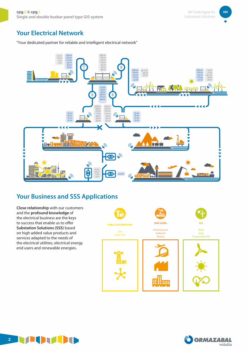
Your Electrical Network"Your dedicated partner for reliable and intelligent electrical network"
Your Business and SSS Applications
Close relationship with our customers and the profound knowledge of the electrical business are the keys to success that enable us to offer Substation Solutions (SSS) based on high added value products and services adapted to the needs of the electrical utilities, electrical energy end users and renewable energies.
PUBLIC DISTRIBUTION
T&DSmart Grid
END USERS
InfrastructuresIndustrialTertiary
RES
WindSolar
Dispatchable RES

cpg.0 & cpg.1 Single and double busbar panel type GIS system
MV Switchgear for Substation Solutions
3
Our Product Map (SSS & DNS)We believe that excellence does not lie solely in offering effective products and services, but also in the ability to respond to individual requirements and demands.
We provide our clients with personalised projects for efficient energy management via Primary and Secondary Distribution equipment and solutions.
Our Business Lines
SSS: Substation Solution for primary distribution
DNS: Distribution Network Solutions for secondary distribution
Our products for your segment
cpg.1 cpg.0 gae1250kmax amccibor transfoorma
Power transformersormacontainer Prefabricated
substationsnvl.cibor
cgm.3 gae ga cgmcosmos [IEC - ANSI/IEEE]
cgmcosmos [HN]
ea
ekorsys family transfoorma Distribution transformers
Protection, automation and control
Oil
ConventionalNon-conventional
transforma.tpc transforma.fine Extended range solutions
CURRENT® family
Low voltage boardAdvanced metering, sensing & analytics, monitoring and
communications
Biodegradable dielectric
liquid
organic
Concrete prefabricated transformer substations (TS) Metallic prefabricated TS CEADS Switching nodes
Underground Walk-in Compact
Concrete enclosure for transformer substations (TS) Metallic enclosure for TS
Photovoltaic substation
Mobile substationUnderground Walk-in Modular
cpg.0 & cpg.1 Single and double busbar panel type GIS system
MV Switchgear for Substation Solutions
4
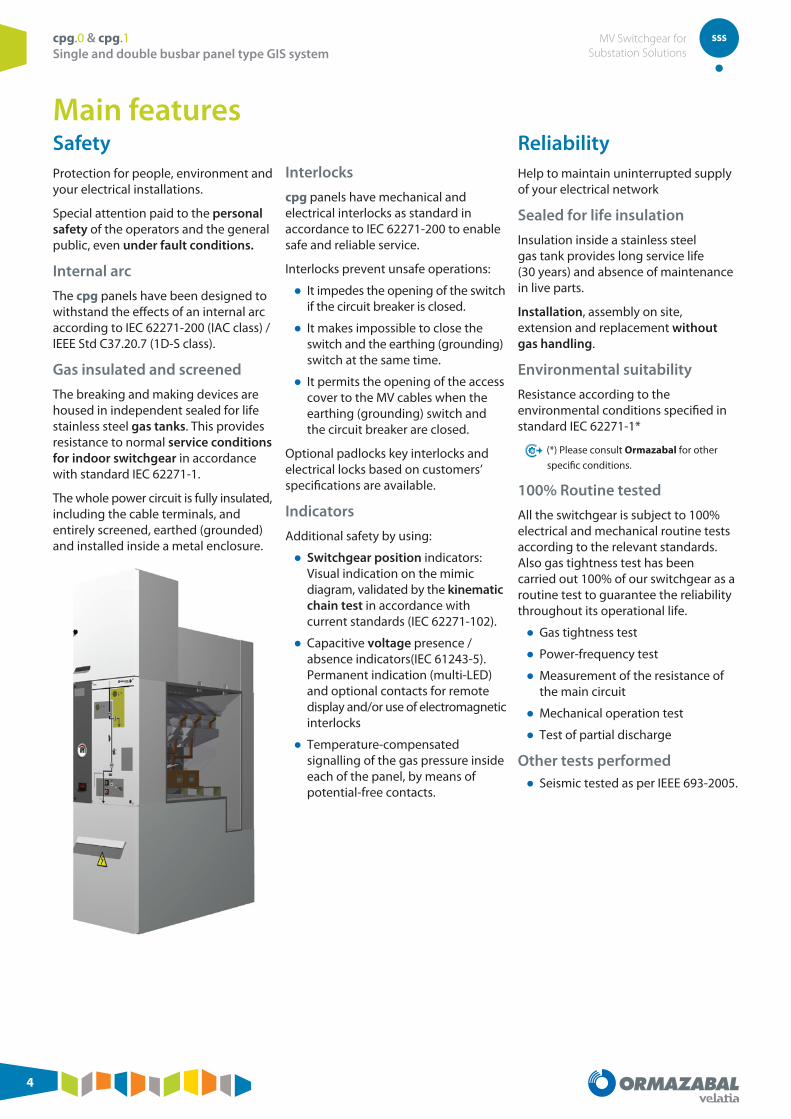
SafetyProtection for people, environment and your electrical installations.
Special attention paid to the personal safety of the operators and the general public, even under fault conditions.
Internal arc
The cpg panels have been designed to withstand the effects of an internal arc according to IEC 62271-200 (IAC class) / IEEE Std C37.20.7 (1D-S class).
Gas insulated and screened
The breaking and making devices are housed in independent sealed for life stainless steel gas tanks. This provides resistance to normal service conditions for indoor switchgear in accordance with standard IEC 62271-1.
The whole power circuit is fully insulated, including the cable terminals, and entirely screened, earthed (grounded) and installed inside a metal enclosure.
Interlocks
cpg panels have mechanical and electrical interlocks as standard in accordance to IEC 62271-200 to enable safe and reliable service.
Interlocks prevent unsafe operations:
● It impedes the opening of the switch if the circuit breaker is closed.
● It makes impossible to close the switch and the earthing (grounding) switch at the same time.
● It permits the opening of the access cover to the MV cables when the earthing (grounding) switch and the circuit breaker are closed.
Optional padlocks key interlocks and electrical locks based on customers’ specifications are available.
Indicators
Additional safety by using:
● Switchgear position indicators: Visual indication on the mimic diagram, validated by the kinematic chain test in accordance with current standards (IEC 62271-102).
● Capacitive voltage presence / absence indicators(IEC 61243-5). Permanent indication (multi-LED) and optional contacts for remote display and/or use of electromagnetic interlocks
● Temperature-compensated signalling of the gas pressure inside each of the panel, by means of potential-free contacts.
ReliabilityHelp to maintain uninterrupted supply of your electrical network
Sealed for life insulation
Insulation inside a stainless steel gas tank provides long service life (30 years) and absence of maintenance in live parts.
Installation, assembly on site, extension and replacement without gas handling.
Environmental suitability
Resistance according to the environmental conditions specified in standard IEC 62271-1*
(*) Please consult Ormazabal for other
specific conditions.
100% Routine tested
All the switchgear is subject to 100% electrical and mechanical routine tests according to the relevant standards. Also gas tightness test has been carried out 100% of our switchgear as a routine test to guarantee the reliability throughout its operational life.
● Gas tightness test
● Power-frequency test
● Measurement of the resistance of the main circuit
● Mechanical operation test
● Test of partial discharge
Other tests performed ● Seismic tested as per IEEE 693-2005.
Main features

cpg.0 & cpg.1 Single and double busbar panel type GIS system
MV Switchgear for Substation Solutions
5
EfficiencyHigh valuable features that make your task easier
Modularity
cpg design is totally modular. It offers flexible diagram configurations, easy extension to both sides without gas handling.
Extensibility and replaceability
Extensibility on both sides allows a fast and economic installation process, in reduced space, not having to move adjacent panels to remove a central one.
Ergonomics
cpg presents the following user-friendly features:
● Front access to install MV cables and fuses
● Easy connection and testing cables
● Simple interface with operators
● Horizontal fuse holders
● Effortless operation of driving mechanisms
● Optimized dimensions
● Safe access to the control and signalling area
● Reliability of connecting the control and signalling circuits via connectors.
SustainabilityContinuous efforts in gas emission reduction
Commitment to the environment:
● Incessant decrease in use of greenhouse gases
● Negligible SF6 emission in manufacturing processes
● Switchgear gas leakage rates reduction
● No SF6 gas use during installation
● Unceasing measures to reduce our environmental footprint
● End-of-life management
● Use of highly recyclable materials
● Constant research investment in alternative materials and own technology
● Reduction of the panel room dimension, due to its frontal access and design without removable switchgear.
Continuous innovationHelp to maintain uninterrupted supply of your electrical network
A focused team of professionals dedicated to innovation leads to a constant offer of new developments and upgrades, such as:
● New ratings up to 2500 A.
● New values up to 40.5 kV
● New and comprehensive protection and automation functions
● Preventive cable fault diagnosis
● Partial discharge (PD) detection for network diagnosis

cpg.0 & cpg.1 Single and double busbar panel type GIS system
MV Switchgear for Substation Solutions
6
Family
cpg.0 Single busbar
v f s
Circuit breaker Fuse protection Disconnector
rb c
Busbar rise Busbar coupling
cpg.1 Single busbar
v1 f1 s1
Circuit breaker Fuse protection Disconnector
c
Longitudinal busbar
coupling
cpg.1 Double busbar
v2 f2 s2
Circuit breaker Fuse protection Disconnector
cl ct
Longitudinal busbar
coupling
Transversal busbar
coupling
Technical details
Applicable electrical standardsIEC
IEC 62271-1 Common specifications for high voltage switchgear and controlgear standards.
IEC 62271-200 Alternating current metal-enclosed switchgear and controlgear for rated voltages above 1 kV and up to and including 52 kV.
IEC 62271-103 Switches for rated voltages above 1 kV up to and including 52 kV.
IEC 62271-102 Alternating current disconnectors and earthing switches.
IEC 62271-105 High voltage alternating current switch-fuse combinations.
IEC 62271-100 High voltage alternating current circuit-breakers.
IEEE / ANSI
IEEE C37.74 IEEE Standard Requirements for Subsurface, Vault, and Pad-Mounted Load-Interrupter Switchgear and Fused Load-Interrupter Switchgear for Alternating Current Systems Up to 38 kV
IEEE C37.20.3 IEEE Standard for Metal-Enclosed Interrupter Switchgear
IEEE 1247 Standard for Interrupter Switches for Alternating Current, Rated Above 1000 Volts
IEEE C37.123 IEEE Guide to Specifications for Gas-Insulated, Electric Power Substation Equipment
IEEE Std C37.20.4 IEEE Standard for Indoor AC Switches (1 kV-38 kV) for Use in Metal-Enclosed Switchgear
IEEE C37.04 IEEE Standard Rating Structure for AC High-Voltage Circuit Breakers
IEEE C37.06 AC High-Voltage Circuit Breakers Rated on a Symmetrical Current Basis- Preferred Ratings and Related Required Capabilities
IEEE Std C37.09 IEEE Standard Test Procedure for AC High-Voltage Circuit Breakers Rated on a Symmetrical Current Basis
IEEE Std C37.20.7 IEEE Guide for Testing Medium-Voltage Metal-Enclosed Switchgear for Internal Arcing Faults

cpg.0 & cpg.1 Single and double busbar panel type GIS system
MV Switchgear for Substation Solutions
7
Technical dataElectrical characteristics IEC ANSI / IEEE
cpg.0 cpg.1 cpg.0 cpg.1
Rated Voltage Ud [kV] 24 36 40.5 24 36 27 38 27 38
Rated frequency fr [Hz] 50 / 60
Rated normal current Ir
Busbars [A] Up to 2500 Up to 1250 Up to 2000 Up to 22503) Up to 21503) Up to 20003)
Outgoing line1) [A] Up to 2500 Up to 1250 1250 Up to 2000 Up to 2250 Up to 1250 Up to 2000
Rated short-time withstand current
with tk = 1 s – 3 s Ik [kA] 25 25 / 31.5 25 25/31.5
Peak value (max) Ip [kA] 65 65 / 80 65 65/85
Rated insulation level
Rated power-frequency withstand voltage [1 min]
Ud [kV] 50 / 60 70 / 80 95 / 118 50 / 60 70 / 80 50 / 66 80 / 88 60 / 66 80 / 88
Rated lightning impulse withstand voltage Up [kV] 125 / 145 170 / 195 185 / 215 125 / 145 170 / 195 125 / 145 170 / 195 125 / 145 170 / 195
Internal arc classification according to IEC 62271-2002) IAC AFL[R] 25 kA 1 s
AFL[R] 25 kA 1 sAFL 31.5 kA 1 s
AFL[R] 25 kA 1 s AFL[R] 25 kA 1 sAFL 31.5 kA 1 s
Degree of protection IP3X / IP65 (Gas tank)
Loss of service continuity category LSC LSC2
Partition class PM
1) Fuse protection panel = 200 A 2) Equivalent to IEEE C37.20.7 for 1D-S 3) For higher values, please consult Ormazabal
Driving mechanism Vacuum circuit breaker Disconnector
cpg.0 cpg.1 cpg.0 cpg.1
Auxiliary circuits
Tripping coil
Rated voltage [V]24 / 48 / 125 Vcc
220 Vac125 Vcc –
Max. consumption [W] 128 300 –
Minimun voltage coil
Rated voltage [V] 24 / 48 / 125 Vcc –
Max. peak current [A] ≤ 9.6 –
Motorised units
Rated voltage [V] 48 Vcc 125 Vcc 125 Vcc 125 Vcc
Avg. consumption [W] 50 50 220 50
Motor operation time [s] 14 10 7 <5 ≤10
Peak current [A] 4.1 1.2 4.1 <5 ≤2
Service conditions IEC ANSI / IEEE
Type of switchgear Indoor
Ambient temperature
Minimum | Maximum -5 °C* | +40 °C* -23 °F* | 104 °F*
Maximum average ambient temperature, measured over a 24-hour period +35 °C 95 °F
Relative humidity
Maximum average relative humidity, measured over a 24-hour period <95 %
Maximum height above sea level 1,000 m* 3,250 feet*
Solar radiation Negligible
Environmental air pollution (dust, salinity, etc.) Acc. to normal service conditions of IEC 62271-1
Vibrations (seismicity) Acc. to standard IEE 693-2005
* For other conditions, please consult Ormazabal.

cpg.0 & cpg.1 Single and double busbar panel type GIS system
MV Switchgear for Substation Solutions
8
Constructive structure
cpg.0
Front view
cpg.1
Front view
Side view
Side view
1. Gas tank/s1.1. Vacuum circuit breaker1.2. Three-position disconnector
(cpg.0) / Disconnectors (cpg.1)
1.3. Earthing switch (cpg.1)1.4. Pressure relief duct
2. Busbar compartment2.1. Main busbars
3. Base: Cable compartment3.1. Bushings3.2. Current transformers3.3. Voltage transformers3.4. Phase segregation assembly3.5. Terminals
4. Low voltage compartment4.1. Protection, control and
signalling devices
5. Operation interface5.1. Circuit-breaker driving
mechanism5.2. Disconnector/s driving
mechanism5.3. Earthing (grounding) switch
mechanism5.4. Pressure switch (cpg.0)5.5. Voltage presence/absence
indicator5.6. Mimic diagram
cpg ANSI / IEEE type

cpg.0 & cpg.1 Single and double busbar panel type GIS system
MV Switchgear for Substation Solutions
9
Key components
Vacuum circuit breaker (VCB)
Circuit-breaker with vacuum breaking technology, compact and with excellent reliability, certified in accordance to IEC 62271-100 standard, including extended electrical endurance (class E2) with rapid reclosing cycle and hence maintenance-free during its whole service life.
Circuit-breaker
cpg.0 cpg.1
Breaking capacity
Short-circuit (asymmetry)
[kA]
25 (Up to 36 kV)
25/31.5 (40.5 kV)
25 / 31.5
DC >20% >45%
No-load cable-charging breaking capacity
[A]31.5 (24 kV)50 (36 kV)
50 (40.5 kV cpg.0)
Capacitor bank breaking capacity
[A] 400
Electrical endurance E2
Reclosing sequence O-0.3”-CO-15”-CO
Mechanical endurance M2
Rated current [A]
Up to 2500 (24 kV)
Up to 1250 (40.5 kV)
Up to 2000 (24-36 kV)
Rated short-time withstand current
[kA / 1 s - 3 s]
25 25 / 31.5
Opening time [ms] <45
Characteristics:
● Vacuum breaking ● Manual operation through push-
button (lockable with a padlock)
● Motor driving mechanism ● Spring loading time <15 seconds
● Operating coils: ● 1 (cpg.0) and 1 (cpg.1) shunt trip
opening coils. 2nd optional coil. ● 1 closing coil ● 1 undervoltage coil (optional)
Disconnector
High duty disconnector designed and developed by Ormazabal.
Disconnector and earthing (grounding) switch:
cpg.0 cpg.1
Mechanical endurance M0 M0
Earthing (grounding) switch
Making capacity [kA]63 (50 Hz) / 65 (60 Hz)
63-80 (50 Hz) / 65-85 (60 Hz)
Electrical endurance E0 E0
Rated current [A]
24 kV: Up to 2500
40.5 kV:Up to 1250
2000 A
Short-time current [kA –1 / 3 s]
25 25
31.5
Characteristics:
● cpg.0-f: 3 positions (connection - disconnection - earthing)
● Independent actuation and levers for the operations: ● Connection - disconnection [motor
driving mechanism option]
● Disconnection – earthing (grounding) [motor driving mechanism option]
Main busbars
The function of the main busbars is to connect panel-to-panel electrically.
They are single-phase arranged and located outside the sealed gas tank. It allows modularity and future extensibility without gas handling on site or moving adjacent panels.
The upper busbar set consists of three separate cylindrical copper conductors with solid and shielded insulation (6 conductors when double busbar.) Every phase is connected using a busbar segment and “T” or “L” shaped connectors.
The whole set is protected against dirt and condensation; in addition, it has a metal cover to protect it against impacts.
The busbars are prepared to withstand thermal and dynamic forces of rated short-time currents (cpg.0: 25 kA / 1 or 3 s and cpg.1 up to 25-31.5 kA / 1 or 3 s) and rated continuous current up to 2500 A.
Design characteristics
cpg.0 & cpg.1 Single and double busbar panel type GIS system
MV Switchgear for Substation Solutions
10
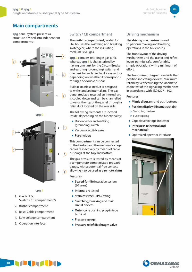
Main compartments
cpg panel system presents a structure divided into independent compartments:
2
1
4
5
3
cpg.0
4
5
3
2
1
cpg.1
1. Gas tank/s: Switch / CB compartment/s
2. Busbar compartment
3. Base: Cable compartment
4. Low voltage compartment
5. Operation interface
Switch / CB compartment
The switch compartment, sealed for life, houses the switching and breaking switchgear, where the insulating medium is SF6 gas.
cpg.0 contains one single gas tank, whereas cpg.1 is characterised by having one tank for the Circuit-Breaker and earthing (grounding) switch and one tank for each feeder disconnectors depending on whether it corresponds to single or double busbar.
Built in stainless steel, it is designed to withstand an internal arc. The gas generated as a result of an internal arc is cooled down and can be channelled towards the top of the panel through a relief duct located on the rear side.
The following elements are located inside, depending on the functionality:
● Disconnector and earthing (grounding)switch.
● Vacuum circuit-breaker.
● Fuse holders
This compartment can be connected to the busbar and the medium voltage cables respectively by means of cable bushings at the top and bottom.
The gas pressure is tested by means of a temperature-compensated pressure gauge, with a potential-free contact, allowing it to be used as a remote alarm.
Features:
● Sealed-for-life insulation system (30 years)
● Internal arc tested
● Stainless steel – IP65 rating
● Switching, breaking and main circuit devices
● Outer-cone bushing plug-in type terminal
● Pressure gauge
● Pressure relief diaphragm valve
Driving mechanism
The driving mechanism is used to perform making and breaking operations in the MV circuits.
The front layout of the driving mechanisms and the use of anti-reflex levers permits safe, comfortable, simple operations with a minimum of effort.
The front mimic diagrams include the position indicating devices. Maximum reliability verified using the kinematic chain test of the signalling mechanism in accordance with IEC 62271-102.
Features:
● Mimic diagram and pushbuttons
● Position display (Kinematic chain) ● Switching devices
● Fuse tripping
● Capacitive voltage indicator
● Interlocks (electrical and mechanical)
● Optimized operator interface

cpg.0 & cpg.1 Single and double busbar panel type GIS system
MV Switchgear for Substation Solutions
11
Busbar compartment
Located in the upper part of the panel, it is used to house the busbar (electrical connection between the Medium Voltage panels).
Each one of the phases that make up the busbar has solid and shielded insulation, earthed (grounded) by means of the compartment's specific earthing bar.
Because of this single-phase arrangement, the panel offers excellent reliability in terms of service continuity.
The installation of a phase segregation assembly using earthed (grounded) metal plates, allows this compartment to withstand internal arcs.
Optionally, toroidal-core current transformers and/or plug-in voltage transformers can be installed in this compartment, without needing metering panels.
Features:
● Single-phase arrangement
● Solid and shielded busbars
● Externaly assembled
● Optional: Toroidal-core current transformers and plug-in voltage transformers
Base
Cable compartment
The cable compartment, located in the lower front section of the panel, has a cover interlocked with the earthing (grounding) switch, thus allowing front access to the Medium Voltage cables.
The external cone-type bushings allow the installation of toroidal-core current transformers on them and the connection of MV insulated cables.
Features:
● Up to 4* reinforced shielded connection terminals (screw-in) per phase.
● Cable bushings up to 2500 A (cpg.0)
● Cable clamps for the medium voltage cables
● Earthing (grounding) bars.
● Effortless connections
● Optional: Toroidal-core current transformers, plug-in voltage transformers and surge arresters.
(*) Up to 6 terminals in cpg.0 (2000/2500 A)
Low voltage compartment
The low voltage compartment placed in the upper part of the panel and independent of the MV compartments, is defined for installing protection relays, as well as metering and control devices.
Features:
● Independent compartment from MV area
● Ready for installing protection relays, control and metering equipment
● Factory assembled and tested according to customer needs
● Standard and compact design for installing Ormazabal’s protection relays and automation, as well as high adaptation capabilities for other manufacturers’ protection relays, control and metering units as well as customers’ provided equipment
● Customized size and design
Attachable low voltage compartments can
be supplied optionally, for the location of
signalling elements and the activation of
motorised functions.

cpg.0 & cpg.1 Single and double busbar panel type GIS system
MV Switchgear for Substation Solutions
12
Protection & Automation cpg switchgear is used a very wide range of areas in power distribution and mostly includes comprehensive protection and control systems to provide the related functions for the application.
cpg is suitable to utilize in substations with conventional protection relays as well as where complex combination of several protection relays and controls systems are required. The devices are installed in the low-voltage compartment of the panels. Indicators and controls are integrated into the front door of the low voltage compartment.
Protection ● Protection functions such as Differential protection Distance protection Overcurrrent time protection Earth fault protection Overload protection Over/under voltage protection Pver/under frequency protection Directional power protection Load unbalance protection Automatic re-starting, etc.
● Substation protection
● Supply to MV customers
● Protection of switching substations and industrial customers
● Generator set protection unit
Automation ● Automation and remote control
● Remote control
● Automatic transfer
● Fault detection
Communication
A wide range of interfaces and protocol structures are available for communication with the control system depending on the device variants used. The connection is made using a data cable or fibre optic cable depending on the system.
ekorsys Family
ekorSYS family is the generic name of all the protection relays, automation, control and communication components and systems that are designed, developed and manufactured by Ormazabal.
The basic products and systems that can be integrated into cpg panels are as follows:
Protection
ekor.rpg
Measurements
● Current: Amperimeter Function
Protection Functions
● Phase overcurrent: 50-51
● Earth overcurrent: 50N-51N
● Ultrasensitive earth leakage protection: 50Ns-51Ns
● Thermometer (external trip): 49T
● Recloser (79)
Communications
● Front port configuration: DB9 RS232
● Rear port remote control RS485 (5kV) –RJ45
● Protocol: MODBUS (RTU)
● Setup and monitoring program ekorsoft (optional)
ekor.rps-tcp
Communications
● Ports: RS-232, RS-485, FOC
● Protocols: MODBUS, PROCOME, IEC-60870-5-101, IEC-60870-5-103, DNP3.0, IEC-61850
Protection ekor.rps-dc and ekor.rps-dd
● Phase overcurrent: (3 x 50/51)
● Earth overcurrent: (50N/51N)
● Current unbalance/ negative sequence current: (46-46FA)
● Breaker failure: (50BF)
● 2nd harmonic restraint
● Ultrasensitive earth overcurrent: (50Ns/51Ns)
● Ultrasensitive earth overcurrent (3 x 67)
● Directional earth fault and sensitive earth fault: (67N), (67Ns)
● Isolated earth directional function: (67NA)
● Voltage restrained overcurrent: (51V)
● Fuse failure
● Thermal image: (49)
Additional features, see next page

cpg.0 & cpg.1 Single and double busbar panel type GIS system
MV Switchgear for Substation Solutions
13
Additional protection ekor.rps-dd
● Maximum frequency / minimum frequency / frequency-derived: (81M / 81m / 81R)
● Directional power: (32)
● Phase overvoltage / phase undervoltage / negative sequence overvoltage (3 x 59 / 3 x 27 / 47)
● Neutral overvoltage: (59N/64)
Control functions
● Three-phase recloser: (79)
● Recloser for single-phase trips due to overcurrent: (79)
● Trip/closure coil supervision: (74)
● Recloser for restart after trip due to frequency trip: (79)
● Synchrocheck: (25)
● Protection status self-diagnosis
Measurements
● Phase, neutral and sensitive neutral currents
● Power factor
● Simple and compound voltages
● Current maximeter
● Energies
● Inverse sequence
● Powers
● Harmonic distortion (THD)
Data acquisition
● Chronological event log
● History log of maximum and minimum measurements
● Chronological fault log
● Oscillography
ekorsys: Automation and remote control
● Remote control ● ekor.uct
● ekor.ccp
● ekor.rci
● Automatic transfer ● ekor.stp
● ekor.ccp
● ekor.rtk
● Fault detection ● ekor.rci
Advanced Meter Management and communication
● ekor.gid
Dispatching center
Software ● ekorsoft
For further information, please refer to
Ormazabal or visit www.ormazabal.com

cpg.0 & cpg.1 Single and double busbar panel type GIS system
MV Switchgear for Substation Solutions
14
Type of modulescpg.0-v
Single busbar circuit-breaker panel
Includes a vacuum circuit-breaker and a three position disconnectorin series with it. Both components are located Both components are located inside the switch compartment.
Electrical characteristics IEC ANSI / IEEE
Rated voltage Ur [kV] 24 36 40.5 27 38
Rated frequency fr [Hz] 50 / 60 60
Rated current
General busbar Ir [A] 1250 / 1600 / 2000 / 2500 1250 1250 / 1600 / 2250** 2150**
Feeder Ir [A]630 / 1250 / 1600 /
2000 / 2500*630 / 1250 1250 / 1600 / 2250* 1250
Rated short-duration power frequency withstand voltage (1 min)
Phase-to-earth (ground) and between phases Ud [kV] 50 70 95 60 80
Across isolating distance Ud [kV] 60 80 118 66 88
Rated lightning impulse withstand voltage
Phase-to-earth (ground) and between phases Up [kV] 125 170 185 125 170
Across isolating distance Up [kV] 145 195 215 145 195
Internal arc classification IAC AFL[R] 25 kA 1 s
Circuit-breaker IEC 62271-100 IEEEC37.20.3Rated short-time withstand current (main circuit)
Value tk = 1 s or 3 s Ik [kA] 25
Peak value Ip [kA] 63 (50 Hz) / 65 (60 Hz) 65
Rated breaking capacity and making capacity
Mainly active current rated breaking capacity I1 [A]630 / 1250 / 1600 /
2000 / 2500*630 / 1250 1250 / 1600 / 2250* 1250
Short-circuit breaking capacity Isc [kA] 25
Capacitive current capacity (50 Hz). Capacitor banks [A] 400
Rated operating sequence
Without reclosing CO-15 s-CO / CO-3 min-CO
With reclosing O-0.3 s-CO-15 s-CO / O-0.3 s-CO-3 min-CO
Circuit-breaker category
Mechanical endurance (operations-class) M2
Electrical endurance (class) E2
Switch IEC 62271-102 IEEE C37.74Rated short-time withstand current (main circuit)
Value tk = 1 s or 3 s Ik [kA] 25
Peak value Ip [kA] 65
Switch Category
Mechanical endurance M1 M0
Cycles of operations (Short-circuit making current)- class E0
Earthing (grounding) Switch IEC 62271-102 IEEE C37.74Rated short-time withstand current (earthing circuit)
Value tk = 1 s or 3 s Ik [kA] 25
Peak value Ip [kA] 63 (50 Hz) / 65 (60 Hz) 65
Main switch making capacity (peak value) Ima [kA] 63 (50Hz) / 65 (60 Hz) 65
Earthing (grounding) Switch Category
Mechanical endurance M1 M0
Cycles of operations (Short-circuit making current)- class E0
* With forced ventilation ** For higher values, please consult Ormazabal
Applications
Main transformer protection, feeder protection, busbar coupling protection, capacitor bank protection and auxiliary services transformer protection.

cpg.0 & cpg.1 Single and double busbar panel type GIS system
MV Switchgear for Substation Solutions
15
Dimensions
[mm]
[in]
Panel structure
Internal arc
F IAC AFL 25 kA 1 s (IEC)
F IAC AFLR 25 kA 1 s (IEC)
Gas tank J Pressure gauge with potential-free
contact
J Voltage presence indicator
F Auxiliary contact
Busbar compartment F Up to 2500 A – 36 kV
F Up to 1250 A – 40.5 kV
F Up to 2250 A – 27 kV
F Up to 2150 A – 38 kV
F Current Transformers
F Voltage Transformers
Driving mechanism
Three-position disconnector
F Disconnector motorization
F Earthing (grounding) switch motorization
Vacuum circuit-breaker
J Motor
J Tripping coil
F 2ndTripping coil
J Closing col
F Undervoltage coil
J Opening/closing push-button blocking
Additional interlocks F Electrical interlocks
F Key lock interlocks
F Pad locks
Cable compartment J Up to 4 cables per phase
F Toroidal-core current transformers
F Plug-in voltage transformer
Low voltage compartment
Panel height
J 2420
F 2245
F Protection, automation, control and signalling devices
J Standard
F Optional
Configuration
IECcpg.0-v
ANSI / IEEEcpg.0-v
ConfigurationWeight
Kg Lbm1) 24 kV 630 A <300 –2) Up to 38 kV ≤ 1600 A
Up to 40.5 kV ≤ 1250 A<850 <1874
3) Up to 27 kV 2000 A <1100 <24254) Up to 36 kV 2500 A
Up to 38 kV 2250 A<1200 <2646

cpg.0 & cpg.1 Single and double busbar panel type GIS system
MV Switchgear for Substation Solutions
16
cpg.0-f
Single busbar fuse protection panel
It has a three-position switch-disconnector (closed/open/earthing-grounding), including fuse protection. The fuses are housed in sealed fuse holders, which in turn are inside the switch compartment, reinforcing the level of insulation.
The three-pole opening switch with combined actuation by fuse blow is optionally motorisable.
Electrical characteristics IEC ANSI / IEEE
Rated voltage Ur [kV] 24 36 40.5 27 38
Rated frequency fr [Hz] 50 / 60 60
Rated current
General busbar Ir [A] 1250 / 1600 / 2000 / 2500 1250 1250 / 1600 / 2250* 1250*
Output to transformer Ir [A] 200
Rated short-duration power frequency withstand voltage (1 min)
Phase-to-earth (ground) and between phases Ud [kV] 50 70 95 60 80
Across isolating distance Ud [kV] 60 80 118 66 88
Rated lightning impulse withstand voltage
Phase-to-earth (ground) and between phases Up [kV] 125 170 125 125 170
Across isolating distance Up [kV] 145 195 145 145 195
Internal arc clasification IAC AFL[R] 25 kA 1 s
Switch-disconnector IEC 62271-103 + IEC 62271-102 IEEE C37.74Rated short-time withstand current (main circuit)
Value tk = 1 s or 3 s Ik [kA] 25
Peak value Ip [kA] 63 (50 Hz) / 65 (60 Hz) 65
Mainly active load-breaking current I1 [A] 630
Main switch making capacity (peak value) Ima [kA] 63 (50 Hz) / 65 (60 Hz) 65
Switch Category
Mechanical endurance M1
Cycles of operations (Short-circuit making current)- class E3 E2
Combined switch-relay take-over current
Breaking Imax acc. TDitransfer >800
Earthing (grounding) Switch IEC 62271-102 IEEE C37.74Rated short-time withstand current (earthing circuit)
Value tk = 1 s or 3 s Ik [kA] 1
Value Ip [kA] 2.5 / 2.6 2.6
Earthing (grounding) switch making capacity (peak value) Ima [kA] 2.5 / 2.6 2.6
Earthing (grounding) Switch Category
Mechanical endurance (manual) M0
Cycles of operations (Short-circuit making current)- class E2
* For higher values, please consult Ormazabal
Applications
Feeder/transformer disconnection, busbar coupling rise and busbar voltage metering.

cpg.0 & cpg.1 Single and double busbar panel type GIS system
MV Switchgear for Substation Solutions
17
Dimensions
[mm]
[in]
Configuration
Panel structure
Internal arc
F IAC AFL 25 kA 1 s (IEC)
F IAC AFLR 25 kA 1 s (IEC)
Gas tank
J Fuses combined with the switch-disconnector
J Pressure gauge with potential-free contact
J Voltage presence indicator
F Auxiliary contact
Busbar compartment
F Up to 2500 A – 36 kV
F Up to 1250 A – 40.5 kV
F Up to 2250 A – 27 kV
F Up to 2150 A – 38 kV
F Current Transformers
F Voltage Transformers
Driving mechanism
Three-position disconnector
F Disconnector motorization
Additional interlocks
F Electrical interlocks
F Key lock interlocks
F Pad locks
Cable compartment
J Up to 4 cables per phase
F Toroidal-core current transformers
F Plug-in voltage transformer
Low voltage compartment
Panel height
J 2420
F 2245
F Protection, automation, control and signalling devices
J Standard
F Optional
ConfigurationWeight
Kg Lbm
<550 <1212
IECcpg.0-f
ANSI / IEEEcpg.0-f

cpg.0 & cpg.1 Single and double busbar panel type GIS system
MV Switchgear for Substation Solutions
18
cpg.0-s
Single busbar Disconnector panel
Includes a three-position disconnector without load breaking capacity.
Electrical characteristics IEC ANSI / IEEE
Rated voltage Ur [kV] 24 36 40.5 27 38
Rated frequency fr [Hz] 50 / 60 60
Rated current
General busbar Ir [A] 1250 / 1600 / 2000 / 2500 1250 1250 / 1600 / 2250** 1250*
Feeder Ir [A] 1250 / 1600 1250 250 / 1600 / 2250 1250
Rated short-duration power frequency withstand voltage (1 min)
Phase-to-earth (ground) and between phases Ud [kV] 50 70 95 60 80
Across isolating distance Ud [kV] 60 80 118 66 88
Rated lightning impulse withstand voltage
Phase-to-earth (ground) and between phases Up [kV] 125 170 185 125 170
Across isolating distance Up [kV] 145 195 215 145 195
Internal arc classification IAC AFL[R] 25 kA 1 s
Switch IEC 62271-102 IEEE C37.74
Rated short-time withstand current (main circuit)
Value tk = 1 s or 3 s Ik [kA] 25
Peak value Ip [kA] 65
Switch Category
Mechanical endurance M1 M0
Cycles of operations (Short-circuit making current)- class E0
Earthing (grounding) Switch IEC 62271-102 IEEE C37.74
Rated short-time withstand current (earthing circuit)
Value tk = 1 s or 3 s Ik [kA] 25
Peak value Ip [kA] 63 (50 Hz) / 65 (60 Hz) 65
Main switch making capacity (peak value) Ima [kA] 63 (50Hz) / 65 (60 Hz) 65
Earthing (grounding) Switch Category
Mechanical endurance M1 M0
Cycles of operations (Short-circuit making current)- class E0
* With forced ventilation ** For higher values, please consult Ormazabal
Applications
Feeder/transformer disconnection, busbar coupling rise and busbar voltage metering.

cpg.0 & cpg.1 Single and double busbar panel type GIS system
MV Switchgear for Substation Solutions
19
Dimensions
[mm]
[in]
Configuration
Panel structure
Internal arc
F IAC AFL 25 kA 1 s (IEC)
F IAC AFLR 25 kA 1 s (IEC)
Gas tank
J Pressure gauge with potential-free contact
J Voltage presence indicator
F Auxiliary contact
Busbar compartment
F Up to 2500 A – 36 kV
F Up to 1250 A – 40.5 kV
F Up to 2250 A – 27 kV
F Up to 2150 A – 38 kV
F Current Transformers
F Voltage Transformers
Driving mechanism
Three-position disconnector
F Disconnector motorization
F Earthing (grounding) switch motorization
Additional interlocks
F Electrical interlocks
F Key lock interlocks
F Pad locks
Cable compartment
J Up to 4 cables per phase
F Toroidal-core current transformers
F Plug-in voltage transformer
Low voltage compartment
Panel height
J 2420
F 2245
F Protection, automation, control and signalling devices
J Standard
F Optional
ConfigurationWeight
Kg Lbm
<550 <1212
IECcpg.0-s
ANSI / IEEEcpg.0-s

cpg.0 & cpg.1 Single and double busbar panel type GIS system
MV Switchgear for Substation Solutions
20
cpg.0-c
Single busbar coupling panel
It includes a vacuum circuit-breaker with two three-position disconnectors in series with it, one upstream and the other downstream from the circuit-breaker.
These elements are located inside the switch compartments.
Electrical characteristics IEC ANSI / IEEE
Rated voltage Ur [kV] 24 36 40.5 27 38
Rated frequency fr [Hz] 50 / 60 50 / 60
Rated current
General busbar Ir [A] 1250 / 1600 / 2000 / 2500 1250 1250 / 1600 / 2250 1250
Rated short-duration power frequency withstand voltage (1 min)
Phase-to-earth (ground) and between phases Ud [kV] 50 70 95 60 80
Across isolating distance Ud [kV] 60 80 118 66 88
Rated lightning impulse withstand voltage
Phase-to-earth (ground) and between phases Up [kV] 125 170 125 125 170
Across isolating distance Up [kV] 145 195 145 145 195
Internal arc classification IAC AFL[R] 25 kA 1 s
Circuit-breaker IEC 62271-100 IEEEC37.20.3Rated short-time withstand current (main circuit)
Value tk = 1 s or 3 s Ik [kA] 25
Peak value Ip [kA] 63 (50 Hz) / 65 (60 Hz) 65
Rated breaking capacity and making capacity
Mainly active current rated breaking capacity I1 [A]630 / 1250 / 1600 /
2000 / 2500*630 / 1250 1250 / 1600 / 2250* 1250
Short-circuit breaking capacity Isc [kA] 25
Rated operating sequence
Without reclosing CO-15 s-CO / CO-3 min-CO
With reclosing O-0.3 s-CO-15 s-CO / O-0.3 s-CO-3 min-CO
Circuit-breaker category
Mechanical endurance (operations-class) M2
Electrical endurance (class) E2
Switch IEC 622713-102 IEEE C37.74Rated short-time withstand current (main circuit)
Value tk = 1 s or 3 s Ik [kA] 25
Peak value Ip [kA] 65
Switch Category
Mechanical endurance M1 M0
Cycles of operations (Short-circuit making current)- class E0
Earthing (grounding) Switch IEC 62271-102 IEEE C37.74Rated short-time withstand current (earthing circuit)
Value tk = 1 s or 3 s Ik [kA] 25
Peak value Ip [kA] 63 (50 Hz) / 65 (60 Hz) 65
Main switch making capacity (peak value) Ima [kA] 63 (50Hz) / 65 (60 Hz) 65
Earthing (grounding) Switch Category
Mechanical endurance M1 M0
Cycles of operations (Short-circuit making current)- class E0
* With forced ventilation
Applications
Longitudinal busbar coupling.

cpg.0 & cpg.1 Single and double busbar panel type GIS system
MV Switchgear for Substation Solutions
21
Dimensions
[mm]
[in]
Configuration
Panel structure
Internal arc
F IAC AFL 25 kA 1 s (IEC)
F IAC AFLR 25 kA 1 s (IEC)
Gas tank J Pressure gauge with potential-free
contact
F Voltage presence indicator
F Auxiliary contact
Busbar compartment F Up to 2500 A – 36 kV
F Up to 1250 A – 40.5 kV
F Up to 2250 A – 27 kV
F Up to 2150 A – 38 kV
F Current Transformers
F Voltage Transformers
Driving mechanism
Three-position disconnector
F Disconnector motorization
F Earthing (grounding) switch motorization
Vacuum circuit-breaker J Motor
J Tripping coil
F 2nd Tripping coil
J Closing col
F Undervoltage coil
J Opening/closing push-button blocking
Additional interlocks: F Electrical interlocks
F Key lock interlocks
F Pad locks
Cable compartment J Lower busbar
F Toroidal-core current transformers
Low voltage compartment
Panel height
J 2420
F 2245
F Protection, automation, control and signalling devices
J Standard
F Optional
ConfigurationWeight
Kg Lbm1) Up to 40.5 kV ≤ 1250 A
Up to 38 kV ≤ 1600 A<1500 <3307
2) Up to 27 kV ≤ 2000 A <2300 <50713) Up to 36 kV ≤ 2500 A
Up to 38 kV ≤ 2250 A<2500 <5512
IECcpg.0-c
ANSI / IEEEcpg.0-c

cpg.0 & cpg.1 Single and double busbar panel type GIS system
MV Switchgear for Substation Solutions
22
cpg.0-rb
Single busbar rise panel
Allows the lateral cable feeder incoming or outgoing for communication with the busbar of the general cubicle assembly and its earthing (grounding).
Electrical characteristics IEC ANSI / IEEE
Rated voltage Ur [kV] 24 36 27 38
Rated frequency fr [Hz] 50 / 60 60
Rated current
General busbar Ir [A] 2500 1250(*) 2250 (*) 1250 (*)
Feeder Ir [A] 1250 / 1600 1250 1250 / 1600 1250
Rated short-duration power frequency withstand voltage (1 min)
Phase-to-earth (ground) and between phases Ud [kV] 50 70 60 80
Rated lightning impulse withstand voltage
Phase-to-earth (ground) and between phases Up [kV] 125 170 125 170
Internal arc classification IAC AFL[R] 25 kA 1 s
* For higher values, please consult Ormazabal
Applications
Busbar lateral feeder.

cpg.0 & cpg.1 Single and double busbar panel type GIS system
MV Switchgear for Substation Solutions
23
Dimensions
[mm]
[in]
Configuration
Panel structure
Internal arc
F IAC AFL 25 kA 1 s (IEC)
F IAC AFLR 25 kA 1 s (IEC)
Gas tank
J Pressure gauge with potential-free contact
F Voltage presence indicator
F Auxiliary contact
Busbar compartment
F Hasta 2500 A – 36 kV
F Hasta 1250 A – 40,5 kV
F Hasta 2250 A – 27 kV
F Hasta 2150 A – 38 kV
F Current Transformers
F Voltage Transformers
Additional interlocks:
F Electrical interlocks
F Key lock interlocks
F Pad locks
Cable compartment
F Toroidal-core current transformers
Low voltage compartment
Panel height
J 2420
F 2245
F Protection, automation, control and signalling devices
J Standard
F Optional
ConfigurationWeight
Kg Lbm
<500 <1102
IECcpg.0-rb
ANSI / IEEEcpg.0-rb

cpg.0 & cpg.1 Single and double busbar panel type GIS system
MV Switchgear for Substation Solutions
24
cpg.1-v
Single (v1) and double (v2) busbar circuit-breaker panel
It includes, in separate compartments, both a circuit-breaker with vacuum breaking technology and an earthing (grounding)switch in series with it, and also feeder disconnectors.
Electrical characteristics IEC (cpg.1-v1 & v2) ANSI/IEEE (cpg.1-v1)
Rated voltage Ur [kV] 24 36 27 38
Rated frequency fr [Hz] 50 / 60 60
Rated current
General busbar Ir [A] 1250 / 1600 / 2000 2000
Feeder Ir [A] 630 / 1250 / 1600 / 2000 2000
Rated short-duration power frequency withstand voltage (1 min)
Phase-to-earth (ground) and between phases Ud [kV] 50 70 60 80
Across isolating distance Ud [kV] 60 80 66 88
Rated lightning impulse withstand voltage
Phase-to-earth (ground) and between phases Up [kV] 125 170 125 170
Across isolating distance Up [kV] 145 195 145 195
Internal arc classification IACAFL[R] 25 kA 1 sAFL 31.5 kA 1 s
Circuit-breaker IEC 62271-100 IEEEC37.20.3Rated short-time withstand current (main circuit)
Value tk = 1 s or 3 s Ik [kA] 25 / 31.5 25/31.5
Peak value Ip [kA]63 / 80 (50 Hz) 65 / 85 (60 Hz)
65 / 85
Rated breaking capacity and making capacity
Mainly active current rated breaking capacity I1 [A] 630 / 1250 / 1600 / 2000 2000
Short-circuit breaking capacity Isc [kA] 25 / 31.5
Capacitive current capacity (50 Hz). Capacitor banks [A] 400
Rated operating sequence
With reclosingO-0.3 s-CO-15 s-CO
O-0.3 s-CO-3 min-CO
Circuit-breaker category
Mechanical endurance (operations-class) M2
Electrical endurance (class) E2
Switch IEC 62271-102 IEEE C37.74Rated short-time withstand current (main circuit)
Value tk = 1 s or 3 s Ik [kA] 25 / 31.5
Peak value Ip [kA]63 / 80 (50 Hz)65 / 85 (60 Hz)
65 / 85
Switch Category
Mechanical endurance M0
Cycles of operations (Short-circuit making current)- class E3
Earthing (grounding) Switch IEC 62271-102 IEEE C37.74Rated short-time withstand current (earthing circuit)
Value tk = 1 s or 3 s Ik [kA] 25/31.5
Peak value Ip [kA]63 / 80 (50 Hz)65 / 85 (60 Hz)
65 / 85
Main switch making capacity (peak value) Ima [kA]63 / 80 (50 Hz)65 / 85 (60 Hz)
65
Earthing (grounding) Switch Category
Mechanical endurance M1 M0
Cycles of operations (Short-circuit making current)- class E0
Applications
Main transformer protection, feeder protection, capacitor bank protection, auxiliary service transformer protection, longitudinal coupling with MV cables.

cpg.0 & cpg.1 Single and double busbar panel type GIS system
MV Switchgear for Substation Solutions
25
Dimensions
[mm]
[in]
Configuration
Panel structure
Internal arc
F IAC AFL 31.5 kA 1 s (IEC)
F IAC AFLR 25 kA 1 s (IEC)
Gas tank
F Voltage presence indicator
Busbar compartment
J Up to 2000 A - 38 kV
F Current Transformers
F Voltage Transformers
Driving mechanism
F Feeder disconnector motorization
F Earthing (grounding) switch motorization
Vacuum circuit-breaker
J Motor
J Tripping coil
F 2nd Tripping coil
J Closing col
F Undervoltage coil
J Opening/closing push-button blocking
Additional interlocks
F Electrical
F Key lock
F Pad locks
Cable compartment
J Up to 4 cables per phase
F Toroidal-core current transformers
F Plug-in voltage transformer
Low voltage compartment
Panel height
J 2720
F Protection, automation, control and signalling devices
J Standard
F Optional
IEC cpg.1-v1 cpg.1-v2
cpg.1-v1
ANSI / IEEE
ConfigurationWeight
Kg Lbm
cpg.1-v1 1100 2425
cpg.1-v2 1400 3086

cpg.0 & cpg.1 Single and double busbar panel type GIS system
MV Switchgear for Substation Solutions
26
cpg.1-f
Single (f1) and double (f2)fuse protection panel
The single busbar variant is equipped with a switchgear compartment with a three-position switch-disconnector (closed / open / earthing), including fuse protection, whereas the double busbar variant is equipped with another two separate switchgear compartments with feeder disconnectors.
The fuses are housed inside sealed fuse holders, these are housed inside the switchgear compartment, and enhanceits insulation level. The combined fuse blow action enables three-pole opening of the switch.
Electrical characteristics IEC (cpg.1-f1 & f2) ANSI/IEEE (cpg.1-f1)
Rated voltage Ur [kV] 24 36 27 38
Rated frequency fr [Hz] 50 / 60 60
Rated current
General busbar Ir [A] 1250 / 1600 / 2000 2000
Output to transformer Ir [A] 200
Rated short-duration power frequency withstand voltage (1 min)
Phase-to-earth (ground) and between phases Ud [kV] 50 70 60 80
Across isolating distance Ud [kV] 60 80 66 88
Rated lightning impulse withstand voltage
Phase-to-earth (ground) and between phases Up [kV] 125 170 125 170
Across isolating distance Up [kV] 145 195 145 195
Internal arc classification IACAFL[R] 25 kA 1 sAFL 31.5 kA 1 s
Switch-disconnector IEC 62271-103 IEEE C37.74Rated short-time withstand current (main circuit)
Value tk = 1 s or 3 s Ik [kA] 25 / 31.5
Peak value Ip [kA]63 / 80 (50 Hz) 65 / 85 (60 Hz)
65 / 85
Mainly active load breaking capacity I1 [A] 630
Main switch making capacity (peak value) Ima [kA]63 / 80 (50 Hz) 65 / 85 (60 Hz)
65 / 85
Switch-disconnector Category
Mechanical endurance M1
Cycles of operations (Short-circuit making current)- class E3
Combined switch-relay take-overcurrent
Breaking Imaxacc.TD itransfer >800
Earthing (grounding) Switch IEC 62271-102 IEEE C37.74Rated short-time withstand current (earthing circuit)
Value tk = 1 s or 3 s Ik [kA] 1/3
Peak value Ip [kA] 2.5 2.6
Main switch making capacity (peak value) Ima [kA] 2.5/7.5
Earthing (grounding) Switch Category
Mechanical endurance M0
Cycles of operations (Short-circuit making current)- class E3 E2
Applications
Auxiliary service transformer protection.

cpg.0 & cpg.1 Single and double busbar panel type GIS system
MV Switchgear for Substation Solutions
27
Dimensions
[mm]
[in]
Configuration
Panel structure
Internal arc
F IAC AFL 31.5 kA 1 s (IEC)
F IAC AFLR 25 kA 1 s (IEC)
Gas tank
J Fuses combined with the switch-disconnector
F Voltage presence indicator
F Visual inspection device
Busbar compartment
J Up to 2000 A – 38 kV
F Current Transformers
F Voltage Transformers
Driving mechanism
F Feeder disconnector motorization
F Earthing (grounding) switch motorization
Additional interlocks
F Electrical
F Key lock
F Pad locks
Cable compartment
J Up to 4 cables per phase
F Toroidal-core current transformers
F Plug-in voltage transformer
Low voltage compartment
Panel height
J 2720
F Protection, automation, control and signalling devices
J Standard
F Optional
IEC cpg.1-f1 cpg.1-f2
cpg.1-f1ANSI / IEEE
ConfigurationWeight
Kg Lbm
cpg.1-f1 1000 2425
cpg.1-f2 1300 2866

cpg.0 & cpg.1 Single and double busbar panel type GIS system
MV Switchgear for Substation Solutions
28
cpg.1-s
Single (s1) and double (s2)disconnector panel
It incorporates feeder disconnectors and earthing (grounding)switches, located in separate compartments.
Electrical characteristics IEC (cpg.1-s1 & s2) ANSI/IEEE (cpg.1-s1)
Rated voltage Ur [kV] 24 36 27 38
Rated frequency fr [Hz] 50 / 60 60
Rated current
General busbar and cubicle interconnection Ir [A] 1250 / 1600 / 2000 2000
Feeder Ir [A] 630 / 1250 / 1600 / 2000 2000
Rated short-duration power frequency withstand voltage (1 min)
phase-to-earth (ground) and between phases Ud [kV] 50 70 60 80
Across isolating distance Ud [kV] 60 80 66 88
Rated lightning impulse withstand voltage
phase-to-earth (ground) and between phases Up [kV] 125 170 125 170
Across isolating distance Up [kV] 145 195 145 195
Internal arc classification IACAFL[R] 25 kA 1 sAFL 31.5 kA 1 s
Switch IEC 62271-102 IEEE C37.74Rated short-time withstand current (main circuit)
Value tk = 1 s or 3 s Ik [kA] 25 / 31.5
Peak value Ip [kA]63 / 80 (50 Hz)65 / 85 (60 Hz)
65 / 85
Switch Category
Mechanical endurance M0
Cycles of operations (Short-circuit making current)- class E3
Earthing (grounding) Switch IEC 62271-102 IEEE C37.74Rated short-time withstand current (earthing circuit)
Value tk = 1 s or 3 s Ik [kA] 25/31.5
Peak value Ip [kA]63 / 80 (50 Hz)65 / 85 (60 Hz)
65 / 85
Main switch making capacity (peak value) Ima [kA]63 / 80 (50 Hz)65 / 85 (60 Hz)
65
Earthing (grounding) Switch Category
Mechanical endurance M1 M0
Cycles of operations (Short-circuit making current)- class E0
Applications
Longitudinal busbar coupling with MV cables.busbar voltage metering with disconnection of the voltage transformers.

cpg.0 & cpg.1 Single and double busbar panel type GIS system
MV Switchgear for Substation Solutions
29
Dimensions
[mm]
[in]
Configuration
Panel structure
Internal arc
F IAC AFL 31.5 kA 1 s (IEC)
F IAC AFLR 25 kA 1 s (IEC)
Gas tank
F Voltage presence indicator
Busbar compartment
J Up to 2000 A – 38 kV
F Current Transformers
F Voltage Transformers
Driving mechanism
F Feeder disconnector motorization
F Earthing (grounding) switch motorization
Additional interlocks
F Electrical
F Key lock
F Pad locks
Cable compartment
J cpg.1-s1: Up to 4 cables per phase
J cpg.1-s2: Up to 3+3 cables per phase
Low voltage compartment
Panel height
J 2720
F Protection, automation, control and signalling devices
J Standard
F Optional
IECcpg.1-s1 cpg.1-s2
cpg.1-s1
ANSI / IEEE
ConfigurationWeight
Kg Lbm
cpg.1-s1 1000 2425
cpg.1-s2 1200 2645

cpg.0 & cpg.1 Single and double busbar panel type GIS system
MV Switchgear for Substation Solutions
30
cpg.1-c / cpg.1-cl
Longitudinal single (c) and double (cl) busbar coupling panelIncludes the following components for each busbar in separate compartments: A vacuum circuit-breaker and the earthing (grounding) switches in series with it in a switchgear compartment and two feeder disconnectors in their corresponding compartments.
Electrical characteristics IEC (cpg.1-c & cl) ANSI/IEEE (cpg.1-c*)
Rated voltage Ur [kV] 24 36 27 38
Rated frequency fr [Hz] 50 / 60 60
Rated current
General busbar Ir [A] 1250 / 1600 / 2000 2000
Feeder Ir [A] 630 / 1250 / 1600 / 2000 2000
Rated short-duration power frequency withstand voltage (1 min)
Phase-to-earth (ground) and between phases Ud [kV] 50 70 60 80
Across isolating distance Ud [kV] 60 80 66 88
Rated lightning impulse withstand voltage
Phase-to-earth (ground) and between phases Up [kV] 125 170 125 170
Across isolating distance Up [kV] 145 195 145 195
Internal arc classification IACAFL[R] 25 kA 1 sAFL 31.5 kA 1 s
Circuit-breaker IEC 62271-100 IEEEC37.20.3Rated short-time withstand current (main circuit)
Value tk = 1 s or 3 s Ik [kA] 25 / 31.5
Peak value Ip [kA]63 / 80 (50 Hz) 65 / 85 (60 Hz)
65 / 85
Rated breaking capacity and making capacity
Mainly active current rated breaking capacity I1 [A] 630 / 1250 / 1600 / 2000 2000
Short-circuit breaking capacity Isc [kA] 25 / 31.5
Rated operating sequence
With reclosingO-0,3 s-CO-15 s-CO
O-0,3 s-CO-3 min-CO
Circuit-breaker category
Mechanical endurance (operations-class) M2
Electrical endurance (class) E2
Switch IEC 62271-102 IEEE C37.74Rated short-time withstand current (main circuit)
Value tk = 1 s or 3 s Ik [kA] 25 / 31.5
Peak value Ip [kA]63 / 80 (50 Hz)65 / 85 (60 Hz)
65 / 85
Switch Category
Mechanical endurance M0
Cycles of operations (Short-circuit making current)- class E3
Earthing (grounding) Switch IEC 62271-102 IEEE C37.74Rated short-time withstand current (earthing circuit)
Value tk = 1 s or 3 s Ik [kA] 25/31.5
Peak value Ip [kA]63 / 80 (50 Hz)65 / 85 (60 Hz)
65 / 85
Main switch making capacity (peak value) Ima [kA]63 / 80 (50 Hz)65 / 85 (60 Hz)
65
Earthing (grounding) Switch Category
Mechanical endurance M1 M0
Cycles of operations (Short-circuit making current)- class E0
* For ANSI/IEEE cpg.1-c type there are two variants: compact type “c” and modular type “m”
Applications Longitudinal busbar coupling.

cpg.0 & cpg.1 Single and double busbar panel type GIS system
MV Switchgear for Substation Solutions
31
Dimensions
[mm]
[in]
Configuration
Panel structure
Internal arc
F IAC AFL 31.5 kA 1 s (IEC)
F IAC AFLR 25 kA 1 s (IEC)
Gas tank
F Voltage presence indicator
Busbar compartment
J Up to 2000 A – 38 kV
F Current Transformers
F Voltage Transformers
Driving mechanism
F Feeder disconnector motorization
F Earthing (grounding) switch motorization
Additional interlocks
F Electrical
F Key lock
F Pad locks
Low voltage compartment
Panel height
J 2720
F Protection, automation, control and signalling devices
Options
IEC ANSI/IEEE cpg.1-cl cpg.1-c (m type)
J Standard
F Optional
IEC
ANSI / IEEE
ConfigurationWeight
Kg Lbm
cpg.1-ccpg.1-c (c type)
1400 3086
cpg.1-c (m type)cpg.1-cl
2800 6172
cpg.1-c (c type)
cpg.1-c

cpg.0 & cpg.1 Single and double busbar panel type GIS system
MV Switchgear for Substation Solutions
32
cpg.1-ct
Transversal busbar coupling panelIncludes the following components in separate switchgearcompartments:
A vacuum circuit-breaker and two earthing (grounding) switches inseries with it in the switchgear compartment, and feederdisconnectors in its corresponding compartments.
Electrical characteristics IEC (cpg.1-ct) ANSI/IEEE (cpg.1-ct)
Rated voltage Ur [kV] 24 36
Rated frequency fr [Hz] 50 / 60
Rated current
General busbar and cubicle interconnection Ir [A] 1250 / 1600 / 2000
Rated short-duration power frequency withstand voltage (1 min)
Phase-to-earth (ground) and between phases Ud [kV] 50 70
Across isolating distance Ud [kV] 60 80
Rated lightning impulse withstand voltage
Phase-to-earth (ground) and between phases Up [kV] 125 170
Across isolating distance Up [kV] 145 195
Internal arc classification IACAFL[R] 25 kA 1 sAFL 31.5 kA 1 s
Circuit-breaker IEC 62271-100 Rated short-time withstand current (main circuit)
Value tk = 1 s or 3 s Ik [kA] 25 / 31.5 25 / 31.5
Peak value Ip [kA]63 / 80 (50 Hz) 65 / 85 (60 Hz)
Rated breaking capacity and making capacity
Mainly active current rated breaking capacity I1 [A] 1250 / 1600 / 2000
Short-circuit breaking capacity Isc [kA] 25 / 31.5
Rated operating sequence
Without reclosingCO-15 s-CO
CO-3 min-CO
With reclosingO-0.3 s-CO-15 s-CO
O-0.3 s-CO-3 min-CO
Circuit-breaker category
Mechanical endurance (operations-class) M2
Electrical endurance (class) E2
Switch IEC 62271-102 Rated short-time withstand current (main circuit)
Value tk = 1 s or 3 s Ik [kA] 25 / 31.5
Peak value Ip [kA]63 / 80 (50 Hz)65 / 85 (60 Hz)
Switch Category
Mechanical endurance M0
Cycles of operations (Short-circuit making current)- class E3
Earthing (grounding) Switch IEC 62271-102 IEEE C37.74Rated short-time withstand current (earthing circuit)
Value tk = 1 s or 3 s Ik [kA] 25/31.5
Peak value Ip [kA]63 / 80 (50 Hz)65 / 85 (60 Hz)
65 / 85
Main switch making capacity (peak value) Ima [kA]63 / 80 (50 Hz)65 / 85 (60 Hz)
65
Earthing (grounding) Switch Category
Mechanical endurance M1 M0
Cycles of operations (Short-circuit making current)- class E0
Applications Transversal busbar coupling.

cpg.0 & cpg.1 Single and double busbar panel type GIS system
MV Switchgear for Substation Solutions
33
Dimensions
[mm]
[in]
Configuration
Panel structure
Internal arc
F IAC AFL 31.5 kA 1 s (IEC)
F IAC AFLR 25 kA 1 s (IEC)
Gas tank
F Voltage presence indicator
Busbar compartment
J Up to 2000 A – 38 kV
F Current Transformers
F Voltage Transformers
Driving mechanism
F Feeder disconnector motorization
F Earthing (grounding) switch motorization
Additional interlocks
F Electrical
F Key lock
F Pad locks
Low voltage compartment
Panel height
J 2720
F Protection, automation, control and signalling devices
J Standard
F Optional
ConfigurationWeight
Kg Lbm
cpg.1-ct 2200 4850
IECcpg.1-ct

cpg.0 & cpg.1 Single and double busbar panel type GIS system
MV Switchgear for Substation Solutions
34
Other components and accessories
Indicators
Voltage presence indicator
Each panel includes a voltage presence/absence detector with permanent light indication and an optional free auxiliary contact for remote display of the corresponding indication.
The indicator, with fixed installation, has been designed according to standard IEC 61243-5 and VDE 0682 Part 415.
Pressure switch
The gas pressure in cpg.0 panels is tested by means of a temperature-compensated pressure gauge, with a potential-free contact, allowing it to be used as a remote alarm.
Optionally in cpg.1, pressure switches for each gas tank can be installed.
cpg.0
cpg.1
Cable connectors
Features:
● For single-core or three core cables.
● For dry cable or impregnated cable.
● Shielded
● Elbow
● Up to 4 screw-in terminals per phase (6 for cpg.0 2000 / 2500 A)
CTs and VTs
Current transformers
Transformers designed by Ormazabal whose main characteristics are:
● Toroidal type
● Encapsulated
● Installed outside the switch compartment, upstream of the medium voltage connectors
● Protected against environmental conditions
● Simple assembly and free of errors during installation (earths)
Installation:
● Busbar compartment and/or cable compartment
Voltage transformers
Characteristics:
● Plug-in type
● Single-phase
● Insulated
● Shieled
● Inductive operation
● Installed outside the switch compartment
● Protected against environmental conditions
Installation:
● Busbar compartment and/or cable compartment
HRC Fuses
Protection against short circuits in the Medium Voltage network is made by means of the fuse protection functions.
The fuse holder tubes reach a uniform temperature all along the tube when they are placed horizontally inside the gas tank. When the cover is closed, they are fully sealed against floods and external pollution.
Features:
● Horizontal fuse holders
● Front access
● Phase-independent compartments
● Protected within the gas tank
● Insulation and sealing against external agents (pollution, temperature changes, adverse weather conditions, including floods)
● Internal interlocks for a safe access to the fuse holder area
Please, consult Ormazabal for further
information about fuse selection

cpg.0 & cpg.1 Single and double busbar panel type GIS system
MV Switchgear for Substation Solutions
35
Spare parts
Metal enclosure
● Lateral cover
● cpg.1 Front door
Operating levers
Fuse protection
● Fuse holder carriage
Handling ● Reduced size and weight make easier manipulation and installation tasks
● Safe panel delivery: ● Upright position on a pallet, wrapped
in protective plastic with polystyrene corner pieces
● Handling methods: ● Lifting: Forklift truck or hand-operated
pallet jack Alternative method: rollers underneath
● Raising: Slings & lifting beams
For handling and installation instructions
request the corresponding manuals to
Ormazabal.
Connection between panelsThe interconnection between panels is external to the switch compartment and is made with busbars with solid and shielded insulation, designed to allow uninstalling a functional unit without having to move the adjacent units and without gas handling.
Phase segregation between busbars
Phase segregation between cables
Handling, installation and after sales

cpg.0 & cpg.1 Single and double busbar panel type GIS system
MV Switchgear for Substation Solutions
36
Inside buildings ● Easy handling with pallet jack.
● Reduced dimensions and minimum space required for its location, due to its careful design and use of SF6 gas as insulating medium.
● Modularity and extensibility on both sides, allowing a fast and economic installation process, in reduced space and without using gas on site, not having to move adjacent panels to remove a central panel.
● Reduction of the panel room dimension, due to its frontal access and design without removable switchgear, and not requiring a rear access space.
● Optimisation of installation and civil work costs due to its reduced dimensions and little need of operation space.
The minimum distances [mm] (inch) recommended for a correct installation, once placed in their final location, are:
For cpg.0:
* Not required with pressure relief duct. ** According to Annex A of standard IEC 62271-200 (Cable trench depth depending on cable bend radius)
For cpg.1
* Not needed with pressure relief duct. ** Removal: >2004. *** In accordance with Appendix A of standard IEC 62271-200 (Cable trench depth depending on cable bend radius).
For other dimensions, please consult
Ormazabal.
Inside mobile substationscpg panels can also be installed inside mobile substations.
Inside wind turbines and wind farm substationscpg panels can also be installed inside wind turbines and wind farm substations.

cpg.0 & cpg.1 Single and double busbar panel type GIS system
MV Switchgear for Substation Solutions
37
Commissioning and After Sales
Services
Technical assistance
FAT Pick-up & delivery
Supervision & installation
Commissioning Training
Warranty Inspection & maintenance
Spare part
Repair Retrofitting Recycling
Engineering Procurement EPCM
Recycling and end-of-lifeThe Ormazabal production centres have introduced the corresponding environmental management systems, conforming to the requirements of the international ISO 14001 standard and endorsed by the Environmental Management certificate among others.
cpg system cubicles have been designed and manufactured in accordance with the requirements of international IEC and IEEE standards.
By design, and depending on the models, they have a sealed compartment with SF6 which allows full operation of the equipment throughout its service life (IEC 62271-200).
At the end of the product life cycle, the SF6 gas content must not be released into the atmosphere. It is recovered and treated for reuse, in accordance with the instructions given in standards IEC 62271-303, IEC 60480 and the CIGRE 117 guide. Ormazabal will provide the additional information required to carry out this task correctly, out of respect for the safety of individuals and that of the environment.

CA-110-EN-1501
www.ormazabal.com