Energy Australia Chamber Substation indoor switchgear/media/Files/Network/Documents/NS and... ·...
36
1 Energy Australia Chamber Substation indoor switchgear installation,operation and maintenance instructions version 1.6 / February 2009
Transcript of Energy Australia Chamber Substation indoor switchgear/media/Files/Network/Documents/NS and... ·...

1
Energy Australia Chamber Substation indoor switchgear installation,operation and maintenance instructions version 1.6 / February 2009

2
Details of revision Version Comment Date 1.0 First Draft Issue May 2006
1.1 Includes
comments and corrections from customer
July 2006
1.2 Includes additional comments from customer
August 2006
1.3 Information on securing SA Neutral earthing cable added
August 2006
1.4 Design changes incorporated
April 2007
1.5 EA Comments August 2007 1.6 Details of
Busway Chamber added
February 2009
contents
3
Page
GENERAL DESCRIPTION 4 Introduction 4 Weights and dimensions 4 Lifting instructions 5
INSTALLATION 7 Installation of panels 7 Removal of lifting lugs 7 Connection of panels 7 Fitting of main busbars 8 Fitting of Earth bar 10 Main cable connection 10 Fitting of Busbar Ventilation Roof 11 Fitting of Busway Top Chamber 12 Fitting of End Plates 14 Fitting of Surge arrester end panel 15 Auxiliary wiring ducts 17 Kit contents 18 Surge arrester end panel kit (EEAABB) 20
OPERATION 21 Operation of circuit breaker 21 Test point access 28
ARCHITECTURE 29 Circuit breaker incoming panels 29 Customer Cable Supply panels 30 1600A Fused Distributor panel 31 Customer Busbar Supply panels 32 Bus-section panel 33 Fused Distributor panel 34
MAINTENANCE 35 routine maintenance 35 general maintenance 36

General description
4
General description Introduction These instructions cover all operations concerning handling, installation, operation and maintenance of the Chamber Substation panels for Energy Australia. The range comprises:- • 3000A Incoming Type 1 & 2 • 2000A Incoming Type 1 & 2 • 3000A Bus-section • 3000A Customer supply – switch –
cable Types 1 & 2 • 3000A Customer supply – circuit
breaker – cable Types 1 & 2 • 3000A Customer supply – switch –
busbar Types 1 & 2
• 3000A Customer supply – circuit breaker – busbar Types 1 & 2
• 3000A Customer supply – link – busbar
• 1600A distributor panel • Fused distributor panel
Weights and dimensions
unit(s) Standard Fused distributor Bus-section W x H x D W x H x D W x H x D average dimensions (mm)
650 x 1943 x 779 650 x 1943 x 779 950 x 1943 x 779
With busbar ventilation chamber fitted
650 x 2243 x 779 650 x 2243 x 779 950 x 2243 x 779
average weight (kg) 650 430 890 (packed) Maximum weight (kg)* 720 450 910 (packed) * Maximum weight includes for a single freestanding unit that includes all available options.
storage
5
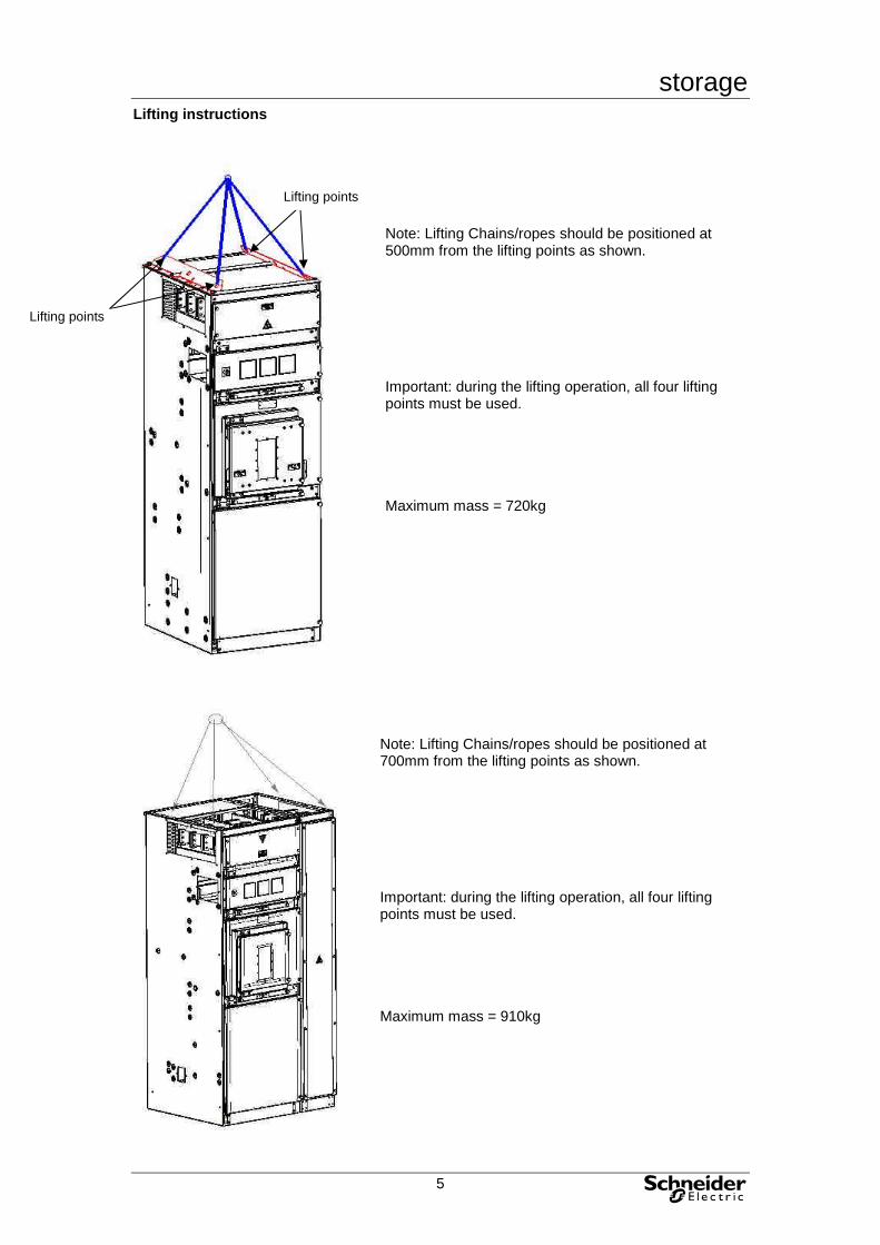
Lifting instructions
Note: Lifting Chains/ropes should be positioned at 500mm from the lifting points as shown. Important: during the lifting operation, all four lifting points must be used. Maximum mass = 720kg
Note: Lifting Chains/ropes should be positioned at 700mm from the lifting points as shown. Important: during the lifting operation, all four lifting points must be used. Maximum mass = 910kg
Lifting points
Lifting points

storage
6
Storage The equipment is suitable for indoor use only. It is therefore
necessary to protect the equipment from the environment before and during erection/commissioning. Should the busbar chamber or cable box become exposed to the elements, they should be thoroughly cleaned prior to energising.
Offloading All units are offloaded using the lifting lugs that are fitted to
the units as standard and should be offloaded using an overhead crane (see diagrams on previous page.).
Storage These units are designed for indoor use only and must not be left outdoors. They should be stored in a warm, dry switchroom and protected against dust and debris.
Ancillary kits The ancillary kits (cubicle jointing kit, cubicle end plate kit) are either supplied loose with each unit, fastened to the panel, or secured in the cable box.
storage
7
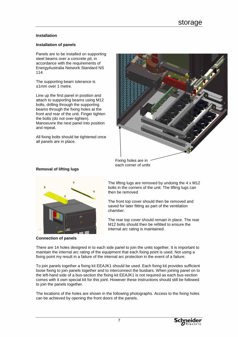
Installation Installation of panels Panels are to be installed on supporting steel beams over a concrete pit, in accordance with the requirements of EnergyAustralia Network Standard NS 114. The supporting beam tolerance is ±1mm over 1 metre. Line up the first panel in position and attach to supporting beams using M12 bolts, drilling through the supporting beams through the fixing holes at the front and rear of the unit. Finger tighten the bolts (do not over-tighten). Manoeuvre the next panel into position and repeat. All fixing bolts should be tightened once all panels are in place. Removal of lifting lugs
The lifting lugs are removed by undoing the 4 x M12 bolts in the corners of the unit. The lifting lugs can then be removed The front top cover should then be removed and saved for later fitting as part of the ventilation chamber. The rear top cover should remain in place. The rear M12 bolts should then be refitted to ensure the internal arc rating is maintained.
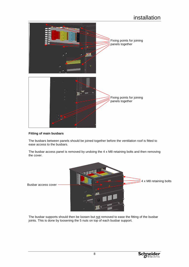
Connection of panels There are 14 holes designed in to each side panel to join the units together. It is important to maintain the internal arc rating of the equipment that each fixing point is used. Not using a fixing point my result in a failure of the internal arc protection in the event of a failure. To join panels together a fixing kit EEAJK1 should be used. Each fixing kit provides sufficient loose fixing to join panels together and to interconnect the busbars. When joining panel on to the left-hand side of a bus-section the fixing kit EEAJK1 is not required as each bus-section comes with it own special kit for this joint. However these instructions should still be followed to join the panels together. The locations of the holes are shown in the following photographs. Access to the fixing holes can be achieved by opening the front doors of the panels.
Fixing holes are in each corner of units
installation
8
Fitting of main busbars The busbars between panels should be joined together before the ventilation roof is fitted to ease access to the busbars. The busbar access panel is removed by undoing the 4 x M8 retaining bolts and then removing the cover.
The busbar supports should then be loosen but not removed to ease the fitting of the busbar joints. This is done by loosening the 5 nuts on top of each busbar support.
Fixing points for joining panels together
Fixing points for joining panels together
4 x M8 retaining bolts Busbar access cover

installation
9
The busbar links and nuts and bolts required can be found as part of kit EEAJK1 The links should be fitted as shown (towards the front) to each busbar in turn starting with the busbar farthest from the front. The M10 x 60 bolts should be fitted with the head towards the front of the panel. Each bolt head and nut should have a belville washer fitted as shown bellow.
The bolts should be tightened using a torque wrench to 46Nm to ensure a good electrical connection. The busbar access panel is re-fitted by reversing the process used to remove it.
installation
10
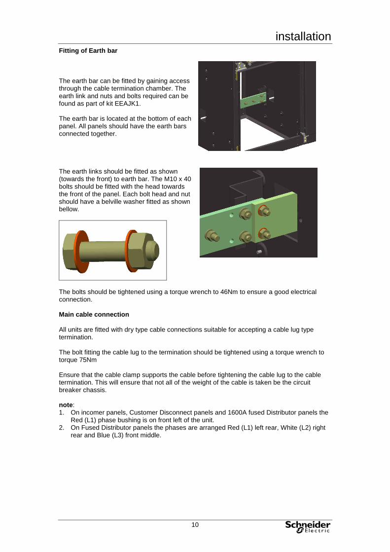
Fitting of Earth bar The earth bar can be fitted by gaining access through the cable termination chamber. The earth link and nuts and bolts required can be found as part of kit EEAJK1. The earth bar is located at the bottom of each panel. All panels should have the earth bars connected together. The earth links should be fitted as shown (towards the front) to earth bar. The M10 x 40 bolts should be fitted with the head towards the front of the panel. Each bolt head and nut should have a belville washer fitted as shown bellow.
The bolts should be tightened using a torque wrench to 46Nm to ensure a good electrical connection. Main cable connection All units are fitted with dry type cable connections suitable for accepting a cable lug type termination. The bolt fitting the cable lug to the termination should be tightened using a torque wrench to torque 75Nm Ensure that the cable clamp supports the cable before tightening the cable lug to the cable termination. This will ensure that not all of the weight of the cable is taken be the circuit breaker chassis. note: 1. On incomer panels, Customer Disconnect panels and 1600A fused Distributor panels the
Red (L1) phase bushing is on front left of the unit. 2. On Fused Distributor panels the phases are arranged Red (L1) left rear, White (L2) right
rear and Blue (L3) front middle.

installation
11
Fitting of Busbar Ventilation Roof The Busbar Ventilation top cover is supplied already fitted to the unit, this will have been removed while removing the lifting lugs and should not be used. The Busbar Ventilation roof is supplied un-assembled. The ventilation roof comprises of two sides, a front panel, a rear-ventilated panel and a roof. The components, including all the M12 bolts, M8 bolts, earthing washers, c form washers and spring washers, required to assemble the roof are supplied as part of the main panel. The sides should be fitted first ensuring that the earthing washer is fitted. Procedure should be repeated for other side. The rear-ventilated panel should then be fitted, earthing washers should be used in two locations, one per bolt. The front cover should also be fitted with earthing washers is a similar location. The roof should then be fitted. Two earthing washers should also be fitted. note: When fitting Earthing Washers they should be fitted with the serrated edge to the panel to ensure they are able to make a good electrical connection.
Earthing washer should be fitted here
Earthing washers should be fitted here
Earthing washers should be fitted here
Serrated edge of Earthing washer

installation
12
Fitting of Busway Top Chamber The Outgoing Busway Top Chamber is supplied un-assembled. The Busway Top Chamber comprises of two sides, a front panel, a rear-ventilated panel, a top cover, a bottom plate and the copper connections. The components, including all the M12 bolts, M8 bolts, earthing washers, c form washers and spring washers, required to assemble the roof are supplied as part of the main panel. The bottom plate should be fitted first ensuring that the earthing washer is fitted. The copper connection should then be fitted before the sides to allow full access to the connections. The copper connections are made up of three individual components. All three should be fitted to all phases and neutral. The sides to the chamber should then be fitted ensuring that the earthing washes are fitted.
Earthing washers should be fitted here
X 4

installation
13
The top chamber cover should then be fitted. Two earthing washers should be fitted, The front and rear-ventilated panel should then be fitted, earthing washers should be used in two locations, one per bolt.
Earthing washers should be fitted here
Earthing washers should be fitted here

installation
14
Fitting of End Plates The end plates should be fitted to the panels that are on either end of the substation. There are three end plates to be fitted, one for the busbar aperture, one for the earth bar aperture and one for the auxiliary wiring aperture. The busbar endplate is made up of two parts, the polycarbonate plate should be sandwiched between the panel and the steel plate on the outside. The polycarbonate end plate must be fitted to ensure the internal arc rating of the panel is maintained. All M8 bolts, washers, spring washers and nuts required are provided as part of the EEAEP1 kit. When fixing the Busbar endplate, the Earth bar endplate and the auxiliary end plate one of the fixing used should be fitted with earthing washers on both the inside of the panel and on the outside of the endplate.
Busbar end plate should be fitted here
Auxiliary wiring end plate should be fitted here
Earth bar end plate should be fitted here

installation
15
Fitting of Surge arrester end panel The surge arrester end panel can be fitted to either the left hand or right hand side. The end panel kit (EEAABB) is supplied normal built to be fitted to the right hand side and will need to be re-assembled if it is required to fit the unit to the left hand side. The surge arresters are supplied as a part of the EEAABB kit. To fit the surge arrester panel the cover first need to be removed. This is done by removing the 10 x M8 bolts. If the surge arrester needs to be fitted to the left hand side then the fuse fittings should be removed and refitted the opposite way up. The busbar extensions should then be fitted using the M10 x 60mm bolts fitted in the same way as the busbar jointing kit is fitted (see page 8) and tighten using a torque wrench to a torque of 46Nm. Once main housing for the surge arresters should then be fitted to the panel using the 6 x M8 bolts provided. The surge arrester should then be fitted as shown in the picture using cable to connect the surge arresters to the relevant busbar extension. The panel covers then need to be refitted, as the panel with the fuses is fitted the cable from the fuses should also be fitted to the relevent busbar extension so as to give the correct phase indication. A semitransparent model of the surge arrester panel is shown so as to indicate were to fit the cable lugs to allow for correct operation.
installation
16
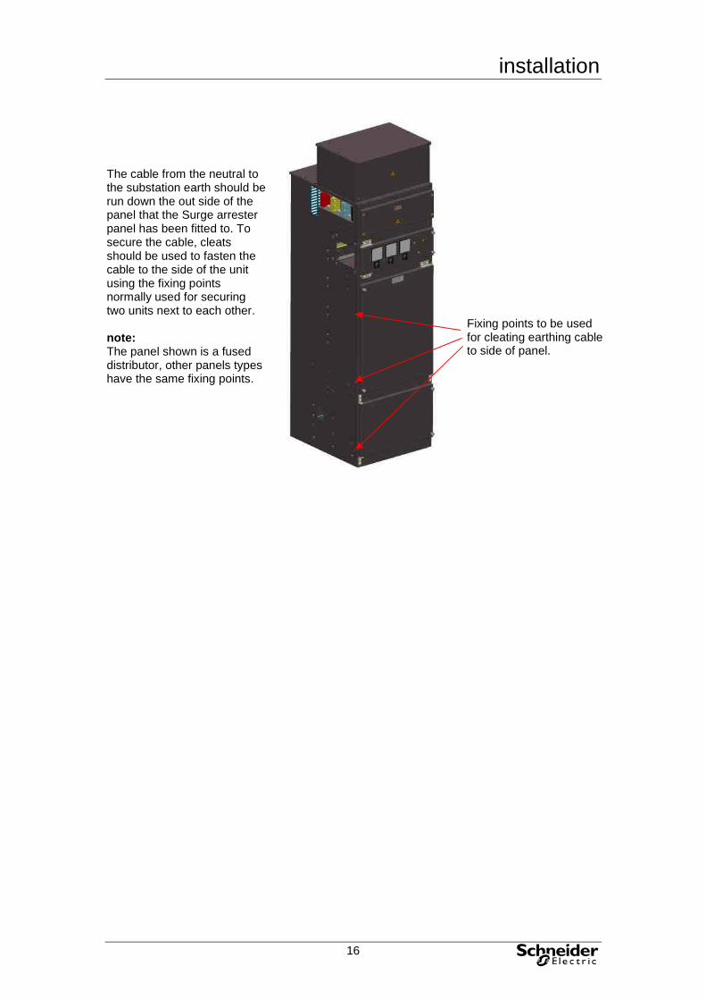
The cable from the neutral to the substation earth should be run down the out side of the panel that the Surge arrester panel has been fitted to. To secure the cable, cleats should be used to fasten the cable to the side of the unit using the fixing points normally used for securing two units next to each other. note: The panel shown is a fused distributor, other panels types have the same fixing points.
Fixing points to be used for cleating earthing cable to side of panel.

installation
17
Auxiliary wiring ducts Two cable ducts are provided on all panels except the bus-section panels. There is a cable duct on each side of the panels that allows auxiliary wiring to be routed from the cable box to the auxiliary wiring panel. Auxiliary wiring for bus-sections should be routed through the panels that are situated on either side of the units and passed through the auxiliary wiring aperture. The auxiliary wiring should be pulled up to the auxiliary wiring panel from the cable box by using a draw wire.
Auxiliary wiring duct shown on right hand side of panel, left hand side duct similar.

installation
18
Kit contents Below is a list of the contents of each optional kit. Cubicle jointing kit (EEAJK1) The following is included in this kit :
8 busbar links
1 earth link
24 M10 x 60 Hex HD bolts
4 M10 x 40 Hex HD bolts
56 M10 Belville washers 41260430
28 M10 Full Nuts
14 M8 x 20 Hex HD bolts
28 M8 B form washers
14 M8 spring washers
14 M8 Full nuts

installation
19
Cubicle end plate kit (EEAEP1) The following is included in this kit :
1 polycarbonate busbar end plate
1 steel busbar end plate
1 steel LV auxiliary end plate
1 steel earth end plate
6 M8 x 30 Hex HD bolts
4 M8 x 20 Hex HD bolts
6 M8 earthing washers
8 M8 form B washers
10 M8 spring washers
10 M8 Full nuts 41200080
operation
20
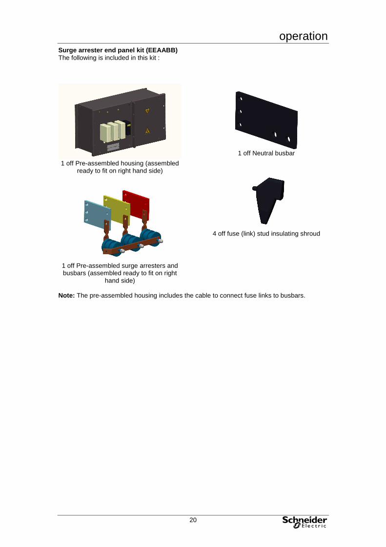
Surge arrester end panel kit (EEAABB) The following is included in this kit :
1 off Pre-assembled housing (assembled
ready to fit on right hand side)
1 off Pre-assembled surge arresters and busbars (assembled ready to fit on right
hand side)
1 off Neutral busbar
4 off fuse (link) stud insulating shroud
Note: The pre-assembled housing includes the cable to connect fuse links to busbars.

operation
21
Operation Due to the fact that the panels have an internal arc rating the normal operating procedures for the Masterpact NW should not be followed. The following instructions should be used when operating the Masterpact to ensure that the internal arc rating of the switchboard is maintained. Warning The doors must be closed and the knurled screws fully tightened to maintain the
internal arc fault capability. Operation of circuit breaker The Masterpact indications can be seen through the window on the front of the panel. The open and close operations of the circuit breaker are done using the open and close levers on the front panel. understanding the controls and indications

operation
22
charging the circuit breaker The springs in the circuit breaker operating mechanism must be charged to store the energy required to close the main contacts. The springs may be charged manually using the charging handle or the optional MCH gear motor. Manual charging: To charge the circuit breaker the front access panel must first be opened. Pull the handle down seven times until you hear a "clack".
Do not close or open the Masterpack with the front access panel open. Automatic charging: If the MCH gear motor is installed, the spring is automatically recharged after each closing. closing the circuit breaker Closing (i.e. turning the circuit ON) is possible only if the circuit breaker is "ready to close". The prerequisites are the following: • device open (OFF) • springs charged • no opening order present. If the circuit breaker is not "ready to close" when the order is given, stop the order and start again when the circuit breaker is "ready to close". With the front access panel closed push the ON lever (right hand side lever), the circuit breaker should close immediately. opening the circuit breaker With the front access panel closed push the OFF lever (Left hand side lever), the circuit breaker should open immediately.

operation
23
resetting after a fault trip If the circuit breaker is not equipped with the automatic reset option then the breaker must be reset manually. This is done by opening the front access panel and pressing the reset button, which is located at the top right hand corner of the Masterpact circuit breaker.
identifying the circuit breaker position in the chassis The indicator on the front signals the position of the circuit breaker in the chassis.
• “connected” position
• “test” position

operation
24
• “disconnected” position
Due to the fact that a plug-in control lead is used the only differnce between the circuit breaker being in the “test” position or the “disconnected” position is that the circuit breaker can be withdrawn when in the “disconnected” position. The plug-in control lead can be removed with the circuit breaker is in the “disconnected” position but it is easier to remove the plug-in control lead when the circuit breaker is in the racked out position (see below on how to rack out the circuit breaker). racking Prerequisites To connect and disconnect Masterpact, the crank must be used. The locking systems, padlocks and the racking interlock all inhibit use of the crank. Withdrawing the circuit breaker from the "connected" to "test" position, then to "disconnected" position The circuit breaker is in "connected" position.
The circuit breaker is in "test" position. Remove the crank or continue to "disconnected" position.
The circuit breaker is in "test" position.
The circuit breaker is in "disconnected" position.

operation
25
removing the rails Press the release tabs and pull the rails out.
To put the rails back in, press the release tabs and push the rails in.
inserting Masterpact Position the circuit breaker on the rails. Check that it rests on all four supports.
Open the circuit breaker.
While the circuit breaker is still in the racked out position the plug-in control lead should then be plugged into the circuit breaker. Push the circuit breaker into the chassis, taking care not to push on the control unit.

operation
26
Racking the circuit breaker from the "disconnected" to "test" position, then to "connected" position The device is in "disconnected" position
The device is in "test" position. Remove the crank or continue to "connected" position.
The device is in "test" position.
The device is in "connected" position.
Padlocking or position indication on the front
Locking Pull out the left-hand tab to lock the top shutter.
Insert a padlock (shackle 5 to 8 mm).
operation
27
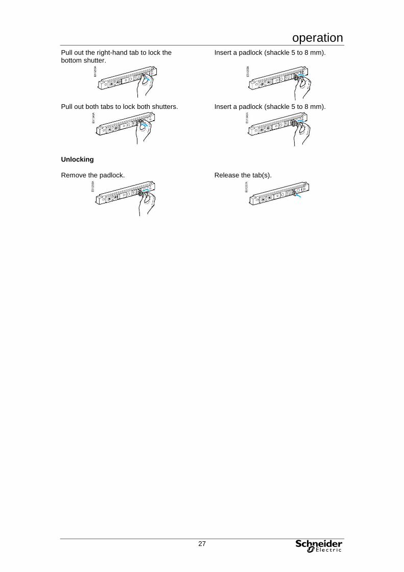
Pull out the right-hand tab to lock the bottom shutter.
Insert a padlock (shackle 5 to 8 mm).
Pull out both tabs to lock both shutters.
Insert a padlock (shackle 5 to 8 mm).
Unlocking Remove the padlock.
Release the tab(s).
operation
28
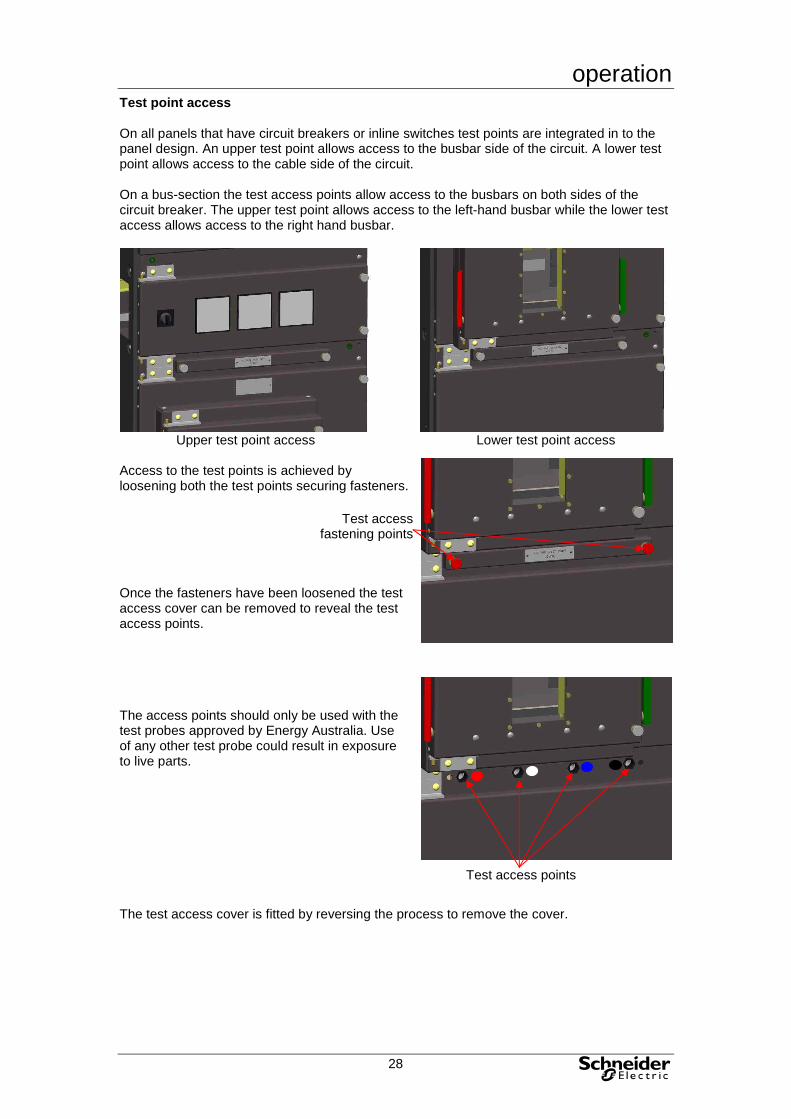
Test point access On all panels that have circuit breakers or inline switches test points are integrated in to the panel design. An upper test point allows access to the busbar side of the circuit. A lower test point allows access to the cable side of the circuit. On a bus-section the test access points allow access to the busbars on both sides of the circuit breaker. The upper test point allows access to the left-hand busbar while the lower test access allows access to the right hand busbar.
Upper test point access
Lower test point access
Access to the test points is achieved by loosening both the test points securing fasteners. Once the fasteners have been loosened the test access cover can be removed to reveal the test access points. The access points should only be used with the test probes approved by Energy Australia. Use of any other test probe could result in exposure to live parts. The test access cover is fitted by reversing the process to remove the cover.
Test access fastening points
Test access points
architecture
29
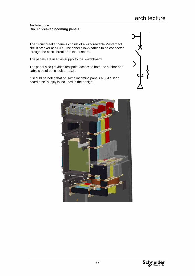
Architecture Circuit breaker incoming panels The circuit breaker panels consist of a withdrawable Masterpact circuit breaker and CTs. The panel allows cables to be connected through the circuit breaker to the busbars. The panels are used as supply to the switchboard. The panel also provides test point access to both the busbar and cable side of the circuit breaker. It should be noted that on some incoming panels a 63A “Dead board fuse” supply is included in the design.
architecture
30
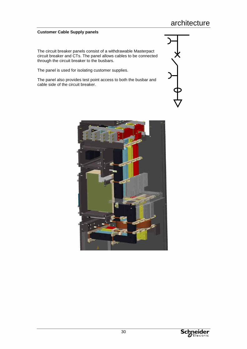
Customer Cable Supply panels The circuit breaker panels consist of a withdrawable Masterpact circuit breaker and CTs. The panel allows cables to be connected through the circuit breaker to the busbars. The panel is used for isolating customer supplies. The panel also provides test point access to both the busbar and cable side of the circuit breaker.

architecture
31
1600A Fused Distributor panel The 1600A Fused Distributor panel consist of a withdrawable Masterpact circuit breaker and large fuses in series. The panel allows outgoing cables to be connected through the circuit breaker and fuses to the busbars. The panel can be fitted with 1600A, 1200A or 1000A fuses. The panel also provides test point access to both the busbar and cable side of the fuses.

architecture
32
Customer Busbar Supply panels The Busbar Supply panel provides a direct busbar connection to the busbars with out any form overload or short circuit of protection. The panel does provide CT in the out going circuit. The panel also provides test point access.

architecture
33
Bus-section panel The Bus-section panel consist of a withdrawable Masterpact circuit breaker and indication CT. The panel allows the busbar to be sectioned in to separate isolated parts or to be part of the same circuit. The panel also provides test point access to both the busbar and cable side of the circuit breaker.
architecture
34
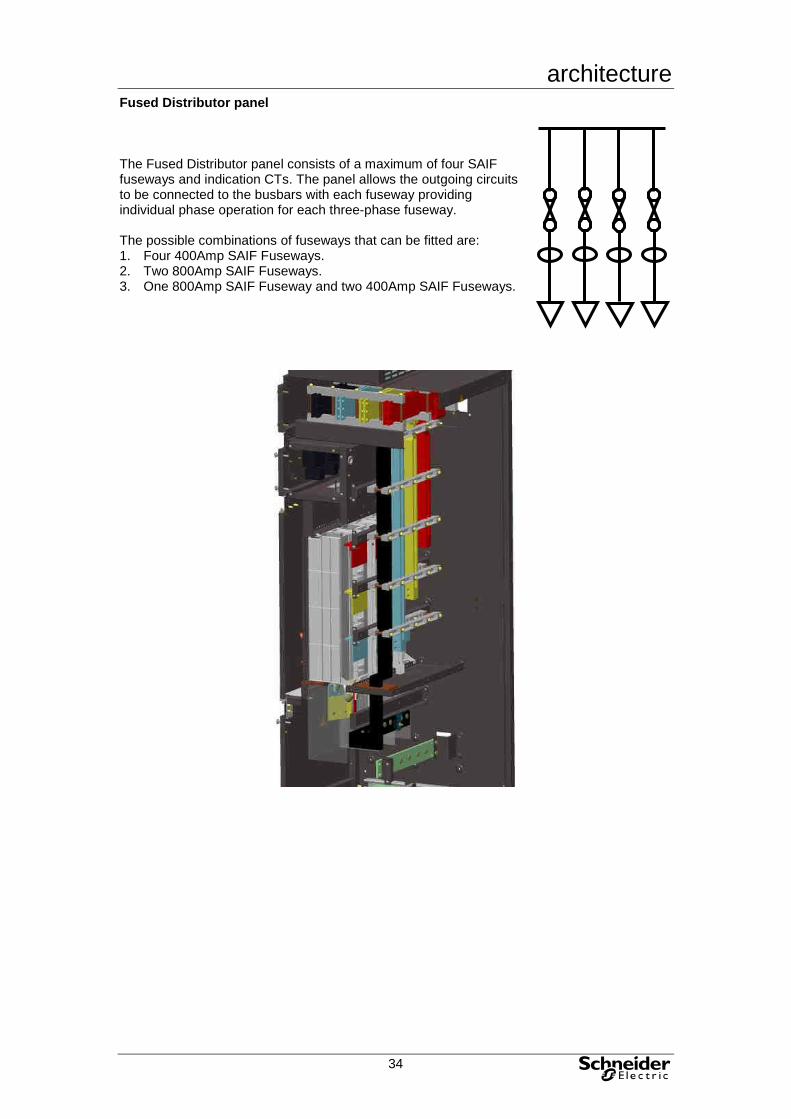
Fused Distributor panel The Fused Distributor panel consists of a maximum of four SAIF fuseways and indication CTs. The panel allows the outgoing circuits to be connected to the busbars with each fuseway providing individual phase operation for each three-phase fuseway. The possible combinations of fuseways that can be fitted are: 1. Four 400Amp SAIF Fuseways. 2. Two 800Amp SAIF Fuseways. 3. One 800Amp SAIF Fuseway and two 400Amp SAIF Fuseways.

maintenance
35
Maintenance routine maintenance recommendations
Routine maintenance will depend on the conditions to which the unit is subjected and to the relevant local codes and practice. Periodic inspection of the
substation and equipment will be necessary to establish the conditions to which the units are subjected.
Periodic inspections required Interval Operations each year • open and close the device locally and remotely,
successively using the various auxiliaries • test the operating sequences • test the control unit using v see the user manual
the mini test kit of the control unit every two years or when the control-unit maintenance indicator reaches 100
• check the arc chutes • check the main contacts • check the tightness of connections • check the disconnecting-contact clusters
Parts requiring replacement, depending on the number of operating cycles The following parts must be replaced periodically to lengthen the service life of the device (maximum number of operating cycles).
Part Intervening entity arc chutes • user main contacts • inspection: user
• replacement: Schneider After Sales Support MCH gear motor • user mechanical interlocks • user connecting-rod springs • Schneider After Sales Support MX/MN/XF • user
Part replacement must be programmed on the basis of the data below, listing the service life of the various parts in numbers of O/C cycles at the rated current. Number of O/C cycles at the rated current Type of circuit breaker
Maximum service life
Service life of various parts
Arc chutes Main contacts Connecting-rod springs, MCH
MX/XF releases
NW08 to NW16 types N1/H1/H2
25000 10000 10000 12500 12500
NW08 to NW16 type L1
25000 3000 10000 12500 12500
NW20 types H1/H2
20000 440 V: 8000 690 V: 6000
440 V: 8000 690 V: 6000
10000 12500
NW20 to NW25 type H3
20000 2000 440 V: 8000 690 V: 6000
10000 12500
NW20 type L1
20000 3000 10000 10000 12500
NW25 to NW40 types H1/H2
20000 440 V: 5000 690 V: 2500
440 V: 5000 690 V: 2500
10000 12500
NW32 to NW40 type H3
20000 1250 440 V: 5000 690 V: 2500
10000 12500
NW40b to NW63 types H1/H2
10000 1500 1500 5000 12500

maintenance
36
general maintenance housing Check all external fixings, labels and earth connections are present and tight. Check inside the cable compartment, busbar system and auxiliary terminal compartment for heavy deposits of dust, ingress of water or contamination by animal or plant life. Clean the units thoroughly and touch up paint work as necessary.