MULTIPLEX COMMUNICATION – MULTIPLEX COMMUNICATION SYSTEM MP–1 MULTIPLEX...
17
MULTIPLEX COMMUNICATION – MULTIPLEX COMMUNICATION SYSTEM MP–1 MP MULTIPLEX COMMUNICATION SYSTEM PRECAUTION 1. DISCONNECT AND RECONNECT CABLE OF NEGATIVE BATTERY TERMINAL NOTICE: When disconnecting the cable from the negative (-) battery terminal, initialize the following systems after the cable is reconnected. (a) Before performing electronic work, disconnect the cable from the negative (-) battery terminal in order to prevent it from shorting and burning out. (b) Before disconnecting and reconnecting the battery cable, turn the ignition switch OFF and the headlight dimmer switch OFF. Then loosen the terminal nut completely. Do not damage the cable or terminal. (c) When the battery cable is disconnected, the clock and radio settings and stored DTCs are erased. Therefore, before disconnecting the battery cable, make a notes of them. System Name See procedure METER / GAUGE SYSTEM See page ME-10 Negative (-) Battery Terminal Cable D033496E01
Transcript of MULTIPLEX COMMUNICATION – MULTIPLEX COMMUNICATION SYSTEM MP–1 MULTIPLEX...
MULTIPLEX COMMUNICATION – MULTIPLEX COMMUNICATION SYSTEM MP–1
P
MMULTIPLEX COMMUNICATION SYSTEMPRECAUTION1. DISCONNECT AND RECONNECT CABLE OF
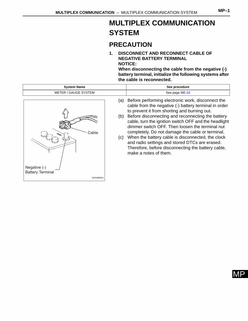
NEGATIVE BATTERY TERMINALNOTICE:When disconnecting the cable from the negative (-) battery terminal, initialize the following systems after the cable is reconnected.
(a) Before performing electronic work, disconnect the cable from the negative (-) battery terminal in order to prevent it from shorting and burning out.
(b) Before disconnecting and reconnecting the battery cable, turn the ignition switch OFF and the headlight dimmer switch OFF. Then loosen the terminal nut completely. Do not damage the cable or terminal.
(c) When the battery cable is disconnected, the clock and radio settings and stored DTCs are erased. Therefore, before disconnecting the battery cable, make a notes of them.
System Name See procedure
METER / GAUGE SYSTEM See page ME-10
Negative (-)
Battery Terminal
Cable
D033496E01
MP–2 MULTIPLEX COMMUNICATION – MULTIPLEX COMMUNICATION SYSTEM
MP
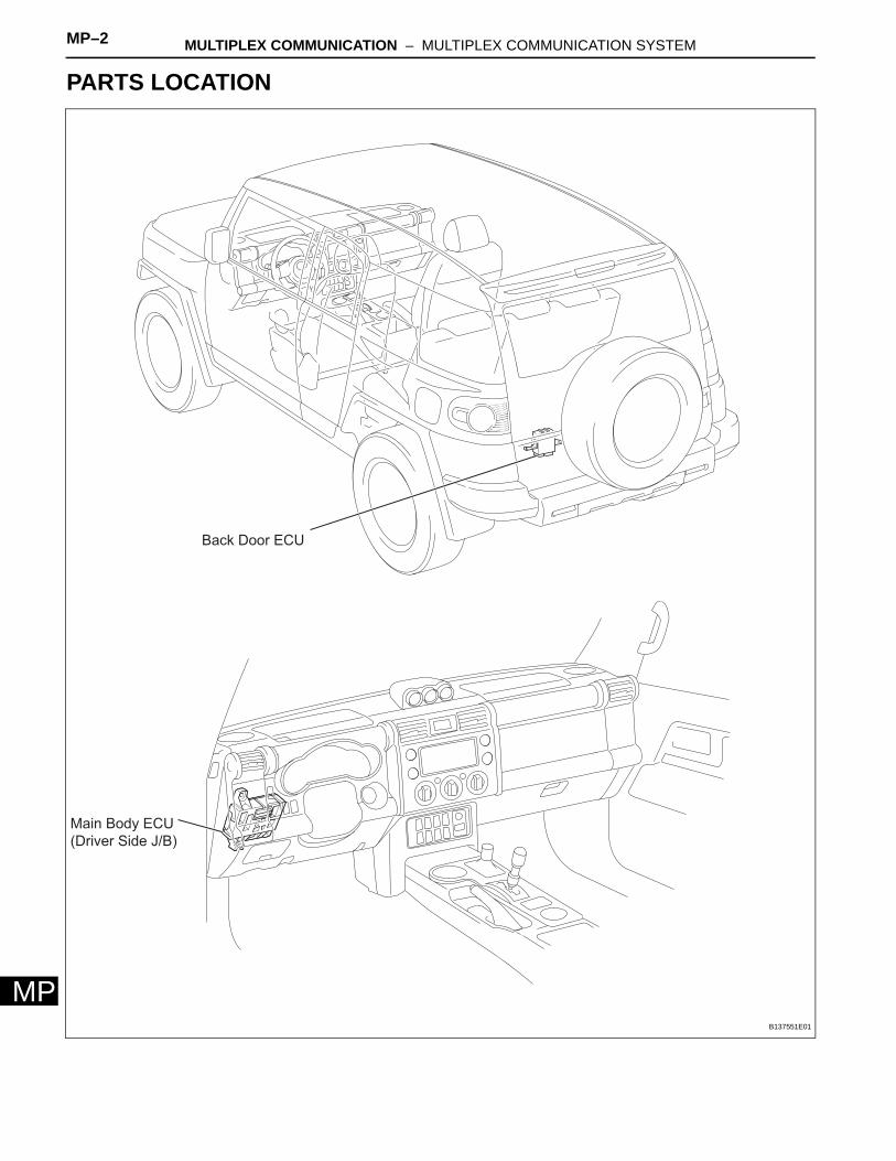
PARTS LOCATION
Main Body ECU
(Driver Side J/B)
Back Door ECU
B137551E01
MULTIPLEX COMMUNICATION – MULTIPLEX COMMUNICATION SYSTEM MP–3
P
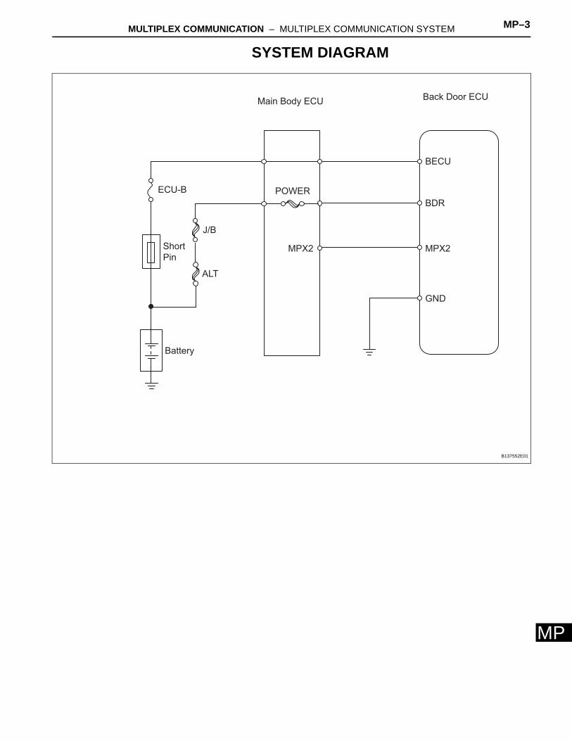
MSYSTEM DIAGRAM
POWER
Back Door ECUMain Body ECU
J/B
ALT
Short
Pin
ECU-B
Battery
BDR
BECU
GND
MPX2 MPX2
B137552E01
MP–4 MULTIPLEX COMMUNICATION – MULTIPLEX COMMUNICATION SYSTEM
MP
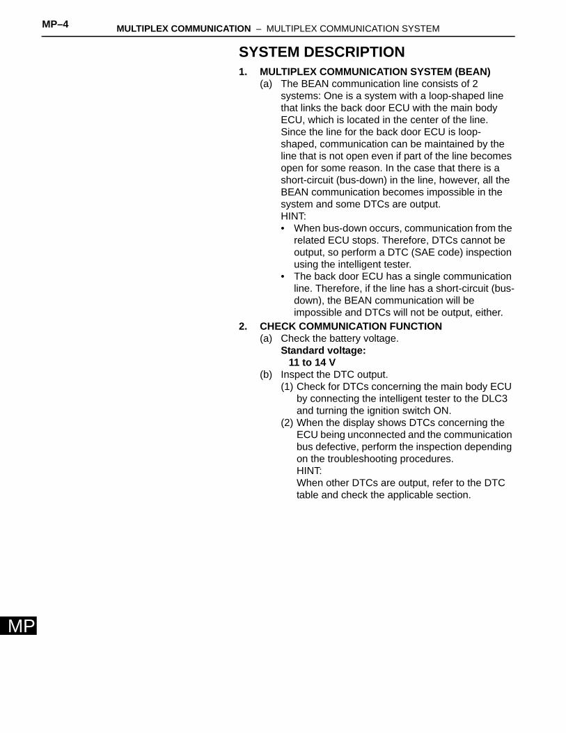
SYSTEM DESCRIPTION1. MULTIPLEX COMMUNICATION SYSTEM (BEAN)
(a) The BEAN communication line consists of 2 systems: One is a system with a loop-shaped line that links the back door ECU with the main body ECU, which is located in the center of the line.Since the line for the back door ECU is loop-shaped, communication can be maintained by the line that is not open even if part of the line becomes open for some reason. In the case that there is a short-circuit (bus-down) in the line, however, all the BEAN communication becomes impossible in the system and some DTCs are output.HINT:• When bus-down occurs, communication from the
related ECU stops. Therefore, DTCs cannot be output, so perform a DTC (SAE code) inspection using the intelligent tester.
• The back door ECU has a single communication line. Therefore, if the line has a short-circuit (bus-down), the BEAN communication will be impossible and DTCs will not be output, either.
2. CHECK COMMUNICATION FUNCTION(a) Check the battery voltage.
Standard voltage:11 to 14 V
(b) Inspect the DTC output.(1) Check for DTCs concerning the main body ECU
by connecting the intelligent tester to the DLC3 and turning the ignition switch ON.
(2) When the display shows DTCs concerning the ECU being unconnected and the communication bus defective, perform the inspection depending on the troubleshooting procedures.HINT:When other DTCs are output, refer to the DTC table and check the applicable section.
MULTIPLEX COMMUNICATION – MULTIPLEX COMMUNICATION SYSTEM MP–5
P
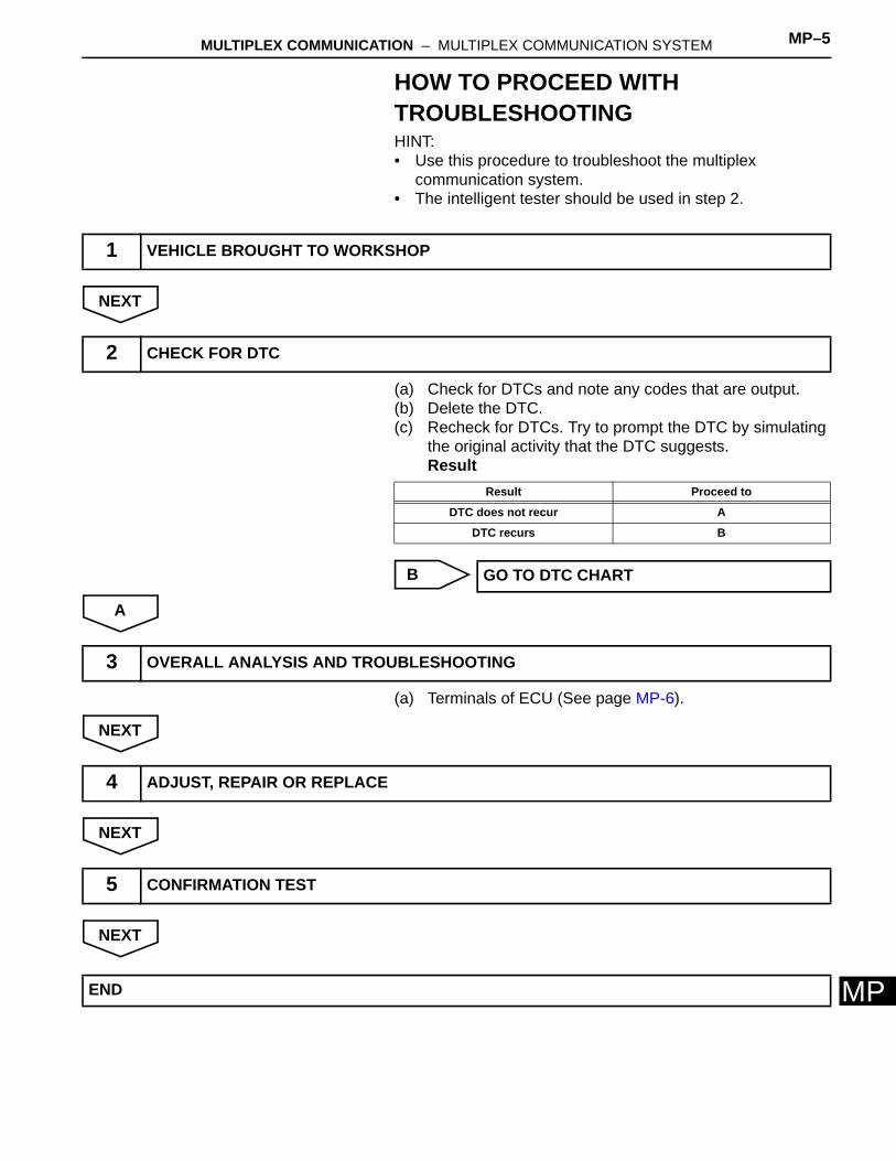
MHOW TO PROCEED WITH TROUBLESHOOTINGHINT:• Use this procedure to troubleshoot the multiplex
communication system.• The intelligent tester should be used in step 2.
NEXT
(a) Check for DTCs and note any codes that are output.(b) Delete the DTC.(c) Recheck for DTCs. Try to prompt the DTC by simulating
the original activity that the DTC suggests.Result
B
A
(a) Terminals of ECU (See page MP-6).
NEXT
NEXT
NEXT
1 VEHICLE BROUGHT TO WORKSHOP
2 CHECK FOR DTC
Result Proceed to
DTC does not recur A
DTC recurs B
GO TO DTC CHART
3 OVERALL ANALYSIS AND TROUBLESHOOTING
4 ADJUST, REPAIR OR REPLACE
5 CONFIRMATION TEST
END
MP–6 MULTIPLEX COMMUNICATION – MULTIPLEX COMMUNICATION SYSTEM
MP
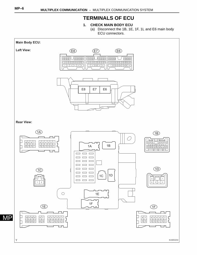
TERMINALS OF ECU1. CHECK MAIN BODY ECU
(a) Disconnect the 1B, 1E, 1F, 1L and E6 main body ECU connectors.
123456
111213141516
78910
17181920
123456
91011121314
78
1516
123456
1314
78
151617181920
910
2122
1112
2324
12345
678910111213
106 9565 844 733 622 511 4
16
3
15
2
14
1
13 2212
30291817 282726252423
2111 2010 199 181787171615141312111098 16151413
24
7
232221262524
1211
2023 1921201918 22
12
34561 2
E6
1A 1B
1D
1F1E
1C
E7E8
E6
1A 1B
1D
1F
1E
1C
E7E8
Main Body ECU:
Left View:
Rear View:
B136051E02
MULTIPLEX COMMUNICATION – MULTIPLEX COMMUNICATION SYSTEM MP–7
P
M12
4 3
1 2 3 4 5 6 7 8
9 10 11 12 13 14 15 16
1
17
2
18
3
19
4
20
5
21
6
22
7
23
8
24
9
25
10
26
11
27
12
28
13
29
14
30
15
31
16
32
1
17
2
18
3
19
4
20
5
21
6
22
7
23
8
24
9
25
10
26
11
27
12
28
13
29
14
30
15
31
16
32
1
2
3
4
1
13
2
14
3
15
4
16
5
17
6
18 19 20
7 9
21
10
22
11
23
12
24
1 2 3 4 5 6 8
1G
1L1K
1J1H
1G
1H
1L
1J
1K
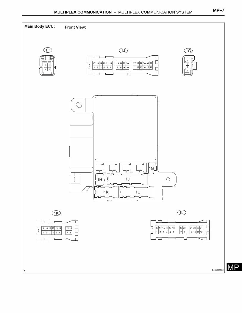
Main Body ECU: Front View:
B136052E02
MP–8 MULTIPLEX COMMUNICATION – MULTIPLEX COMMUNICATION SYSTEM
MP
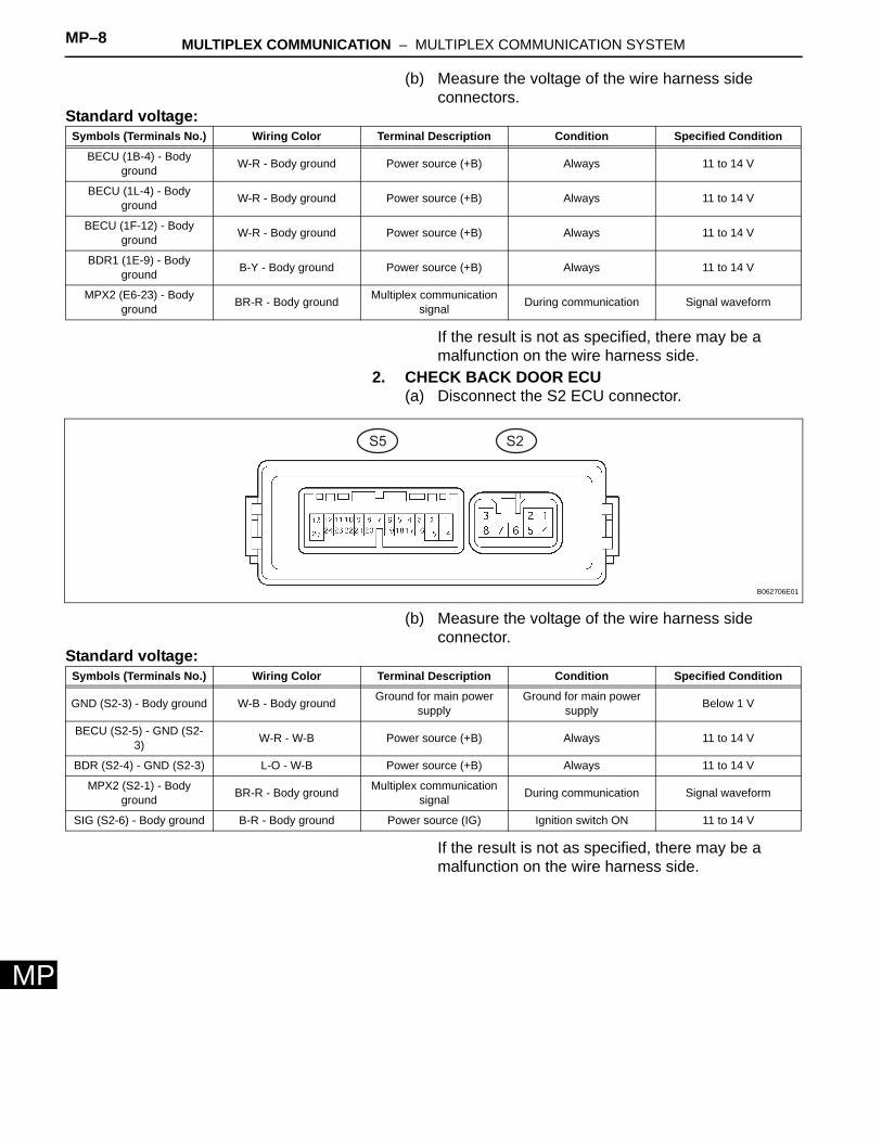
(b) Measure the voltage of the wire harness side connectors.
Standard voltage:
If the result is not as specified, there may be a malfunction on the wire harness side.
2. CHECK BACK DOOR ECU(a) Disconnect the S2 ECU connector.
(b) Measure the voltage of the wire harness side connector.
Standard voltage:
If the result is not as specified, there may be a malfunction on the wire harness side.
Symbols (Terminals No.) Wiring Color Terminal Description Condition Specified Condition
BECU (1B-4) - Body ground W-R - Body ground Power source (+B) Always 11 to 14 V
BECU (1L-4) - Body ground W-R - Body ground Power source (+B) Always 11 to 14 V
BECU (1F-12) - Body ground W-R - Body ground Power source (+B) Always 11 to 14 V
BDR1 (1E-9) - Body ground B-Y - Body ground Power source (+B) Always 11 to 14 V
MPX2 (E6-23) - Body ground BR-R - Body ground Multiplex communication
signal During communication Signal waveform
S2S5
B062706E01
Symbols (Terminals No.) Wiring Color Terminal Description Condition Specified Condition
GND (S2-3) - Body ground W-B - Body ground Ground for main power supply
Ground for main power supply Below 1 V
BECU (S2-5) - GND (S2-3) W-R - W-B Power source (+B) Always 11 to 14 V
BDR (S2-4) - GND (S2-3) L-O - W-B Power source (+B) Always 11 to 14 V
MPX2 (S2-1) - Body ground BR-R - Body ground Multiplex communication
signal During communication Signal waveform
SIG (S2-6) - Body ground B-R - Body ground Power source (IG) Ignition switch ON 11 to 14 V

MULTIPLEX COMMUNICATION – MULTIPLEX COMMUNICATION SYSTEM MP–9
P
MDIAGNOSIS SYSTEM1. DESCRIPTION
(a) The main body ECU controls the functions of the multiplex communication system on the vehicle. Data of the multiplex communication system and the Diagnostic Trouble Codes (DTC) can be read through the Data Link Connector 3 (DLC3) of the vehicle.
2. CHECK DLC3(a) The ECU uses ISO 15765-4 for communication.
The terminal arrangement of the DLC3 complies with ISO 15031-3 and matches the ISO 15765-4 format.
CAUTION:*: Before measuring the resistance, leave the vehicle as is for at least 1 minute and do not operate the ignition switch, any other switches or the doors.If the result is not as specified, the DLC3 may have a malfunction. Repair or replace the harness and connector.
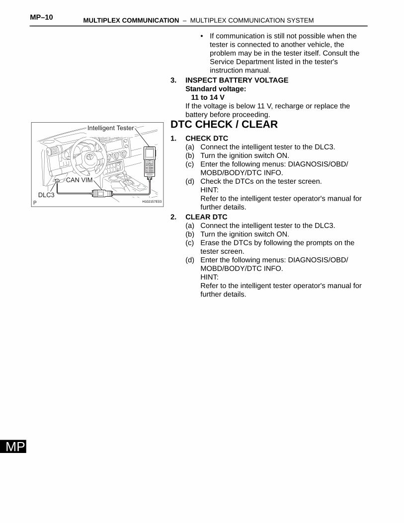
(b) Intelligent testerHINT:Connect the cable of the intelligent tester to the CAN VIM, connect the CAN VIM to the DLC3, turn the ignition switch ON and attempt to use the tester. If the display indicates that a communication error has occurred, there is a problem either with the vehicle or with the tester.• If communication is normal when the tester is
connected to another vehicle, inspect the DLC3 of the original vehicle.
CG SG
BAT
SILCANH
CANLH100769E16
Symbols (Terminal No.) Terminal Description Condition Specified Condition
SIL (7) - SG (5) Bus "+" line During transmission Pulse generation
CG (4) - Body ground Chassis ground Always Below 1 Ω
SG (5) - Body ground Signal ground Always Below 1 Ω
BAT (16) - Body ground Battery positive Always 11 to 14 V
CANH (6) - CANL (14) HIGH-level CAN bus line Ignition switch OFF* 54 to 69 Ω
CANH (6) - CG (4) HIGH-level CAN bus line Ignition switch OFF* 200 Ω or more
CANL (14) - CG (4) LOW-level CAN bus line Ignition switch OFF* 200 Ω or more
CANH (6) - BAT (16) HIGH-level CAN bus line Ignition switch OFF* 6 kΩ or more
CANL (14) - BAT (16) LOW-level CAN bus line Ignition switch OFF* 6 kΩ or more
Intelligent Tester
DLC3
CAN VIM
H102157E03
MP–10 MULTIPLEX COMMUNICATION – MULTIPLEX COMMUNICATION SYSTEM
MP
• If communication is still not possible when the tester is connected to another vehicle, the problem may be in the tester itself. Consult the Service Department listed in the tester's instruction manual.
3. INSPECT BATTERY VOLTAGEStandard voltage:
11 to 14 VIf the voltage is below 11 V, recharge or replace the battery before proceeding.
DTC CHECK / CLEAR1. CHECK DTC
(a) Connect the intelligent tester to the DLC3.(b) Turn the ignition switch ON.(c) Enter the following menus: DIAGNOSIS/OBD/
MOBD/BODY/DTC INFO.(d) Check the DTCs on the tester screen.
HINT:Refer to the intelligent tester operator's manual for further details.
2. CLEAR DTC(a) Connect the intelligent tester to the DLC3.(b) Turn the ignition switch ON.(c) Erase the DTCs by following the prompts on the
tester screen.(d) Enter the following menus: DIAGNOSIS/OBD/
MOBD/BODY/DTC INFO.HINT:Refer to the intelligent tester operator's manual for further details.
Intelligent Tester
DLC3
CAN VIM
H102157E03
MULTIPLEX COMMUNICATION – MULTIPLEX COMMUNICATION SYSTEM MP–11
P
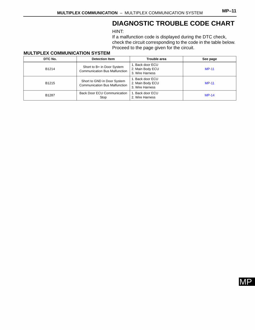
MDIAGNOSTIC TROUBLE CODE CHARTHINT:If a malfunction code is displayed during the DTC check, check the circuit corresponding to the code in the table below. Proceed to the page given for the circuit.
MULTIPLEX COMMUNICATION SYSTEMDTC No. Detection Item Trouble area See page
B1214 Short to B+ in Door System Communication Bus Malfunction
1. Back door ECU 2. Main Body ECU 3. Wire Harness
MP-11
B1215 Short to GND in Door System Communication Bus Malfunction
1. Back door ECU 2. Main Body ECU 3. Wire Harness
MP-11
B1287 Back Door ECU Communication Stop
1. Back door ECU 2. Wire Harness MP-14
MP–12 MULTIPLEX COMMUNICATION – MULTIPLEX COMMUNICATION SYSTEM
MP
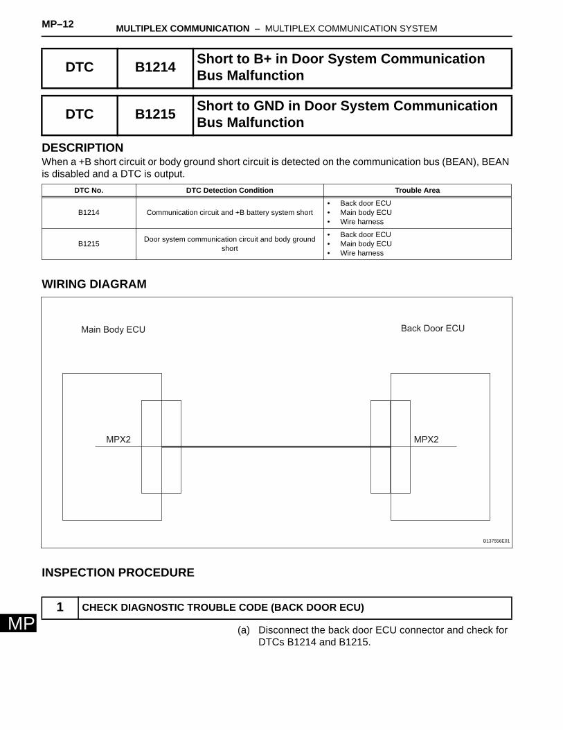
DESCRIPTIONWhen a +B short circuit or body ground short circuit is detected on the communication bus (BEAN), BEAN is disabled and a DTC is output.
WIRING DIAGRAM
INSPECTION PROCEDURE
(a) Disconnect the back door ECU connector and check for DTCs B1214 and B1215.
DTC B1214 Short to B+ in Door System Communication Bus Malfunction
DTC B1215 Short to GND in Door System Communication Bus Malfunction
DTC No. DTC Detection Condition Trouble Area
B1214 Communication circuit and +B battery system short• Back door ECU• Main body ECU• Wire harness
B1215 Door system communication circuit and body ground short
• Back door ECU• Main body ECU• Wire harness
1 CHECK DIAGNOSTIC TROUBLE CODE (BACK DOOR ECU)
Main Body ECU Back Door ECU
MPX2 MPX2
B137556E01
MULTIPLEX COMMUNICATION – MULTIPLEX COMMUNICATION SYSTEM MP–13
P
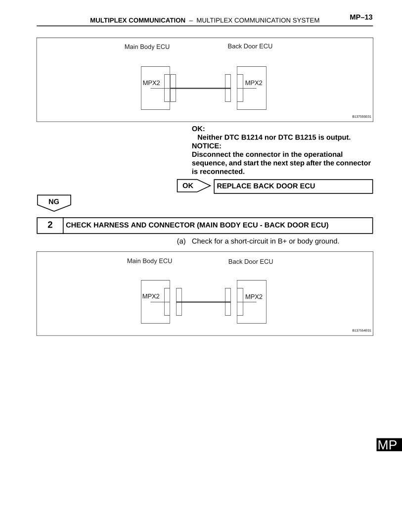
MOK:Neither DTC B1214 nor DTC B1215 is output.
NOTICE:Disconnect the connector in the operational sequence, and start the next step after the connector is reconnected.
OK
NG
(a) Check for a short-circuit in B+ or body ground.
Main Body ECU Back Door ECU
MPX2 MPX2
B137555E01
REPLACE BACK DOOR ECU
2 CHECK HARNESS AND CONNECTOR (MAIN BODY ECU - BACK DOOR ECU)
Main Body ECU Back Door ECU
MPX2 MPX2
B137554E01
MP–14 MULTIPLEX COMMUNICATION – MULTIPLEX COMMUNICATION SYSTEM
MP
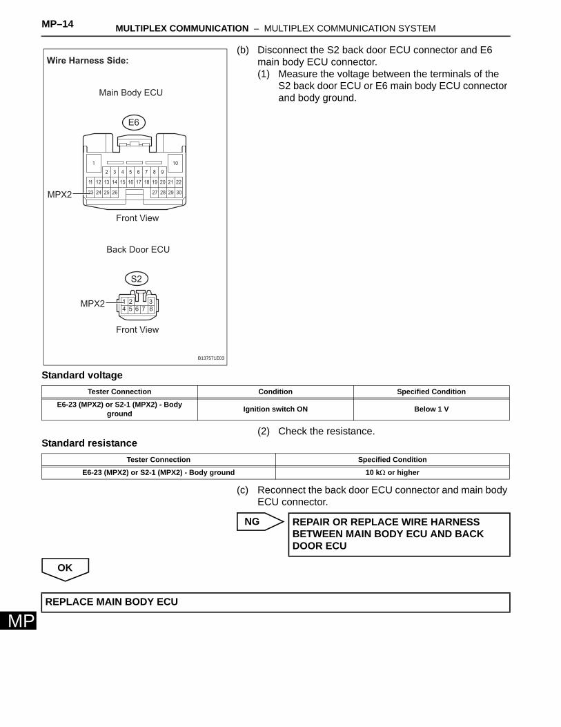
(b) Disconnect the S2 back door ECU connector and E6 main body ECU connector.(1) Measure the voltage between the terminals of the
S2 back door ECU or E6 main body ECU connector and body ground.
Standard voltage
(2) Check the resistance.Standard resistance
(c) Reconnect the back door ECU connector and main body ECU connector.
NG
OK
23
22
26
18
10
25
13 14 16 17 19 2011 12 15
24 27 302928
21
1
2 3 4 5 6 7 8 9
18765432
Wire Harness Side:
Back Door ECU
Main Body ECU
S2
E6
MPX2
MPX2
Front View
Front View
B137571E03
Tester Connection Condition Specified Condition
E6-23 (MPX2) or S2-1 (MPX2) - Body ground Ignition switch ON Below 1 V
Tester Connection Specified Condition
E6-23 (MPX2) or S2-1 (MPX2) - Body ground 10 kΩ or higher
REPAIR OR REPLACE WIRE HARNESS BETWEEN MAIN BODY ECU AND BACK DOOR ECU
REPLACE MAIN BODY ECU
MULTIPLEX COMMUNICATION – MULTIPLEX COMMUNICATION SYSTEM MP–15
P
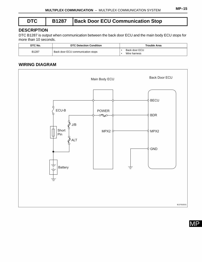
MDESCRIPTIONDTC B1287 is output when communication between the back door ECU and the main body ECU stops for more than 10 seconds.
WIRING DIAGRAM
DTC B1287 Back Door ECU Communication Stop
DTC No. DTC Detection Condition Trouble Area
B1287 Back door ECU communication stops • Back door ECU• Wire harness
POWER
Back Door ECUMain Body ECU
J/B
ALT
Short
Pin
ECU-B
Battery
BDR
BECU
GND
MPX2 MPX2
B137552E01
MP–16 MULTIPLEX COMMUNICATION – MULTIPLEX COMMUNICATION SYSTEM
MP
INSPECTION PROCEDURE
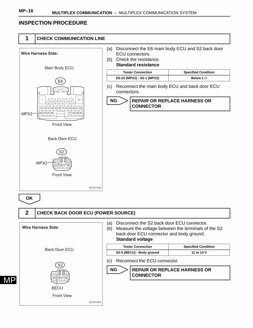
(a) Disconnect the E6 main body ECU and S2 back door ECU connectors.
(b) Check the resistance.Standard resistance
(c) Reconnect the main body ECU and back door ECU connectors.
NG
OK
(a) Disconnect the S2 back door ECU connector.(b) Measure the voltage between the terminals of the S2
back door ECU connector and body ground.Standard voltage
(c) Reconnect the ECU connector.
NG
1 CHECK COMMUNICATION LINE
23
22
26
18
10
25
13 14 16 17 19 2011 12 15
24 27 302928
21
1
2 3 4 5 6 7 8 9
18765432
Wire Harness Side:
Back Door ECU
Main Body ECU
S2
E6
MPX2
MPX2
Front View
Front View
B137571E03
Tester Connection Specified Condition
E6-23 (MPX2) - S2-1 (MPX2) Below 1 Ω
REPAIR OR REPLACE HARNESS OR CONNECTOR
2 CHECK BACK DOOR ECU (POWER SOURCE)
18765432
Wire Harness Side:
Back Door ECU
BECU
S2
Front View
B137572E01
Tester Connection Specified Condition
S2-5 (BECU) - Body ground 11 to 14 V
REPAIR OR REPLACE HARNESS OR CONNECTOR
MULTIPLEX COMMUNICATION – MULTIPLEX COMMUNICATION SYSTEM MP–17
P
MOK
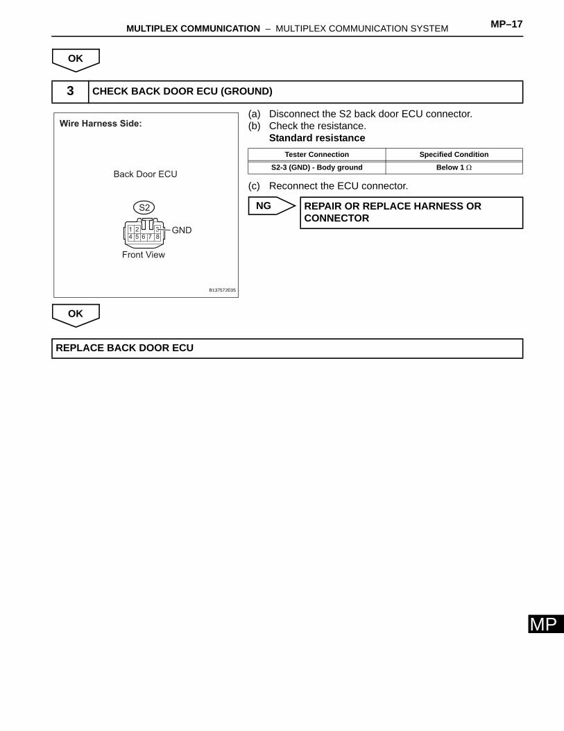
(a) Disconnect the S2 back door ECU connector.(b) Check the resistance.
Standard resistance
(c) Reconnect the ECU connector.
NG
OK
3 CHECK BACK DOOR ECU (GROUND)
18765432
Wire Harness Side:
Back Door ECU
GND
S2
Front View
B137572E05
Tester Connection Specified Condition
S2-3 (GND) - Body ground Below 1 Ω
REPAIR OR REPLACE HARNESS OR CONNECTOR
REPLACE BACK DOOR ECU