Multiplex Beverage Systems Multiplex Beverage …€¦ · Groupe Pompe de Surpresseur d™Eau ........
44
Multiplex Beverage Systems Operations Manual Multiplex Company, Inc. 250 Old Ballwin Road w St. Louis, Missouri 63021-4800 Tel: 636.256.7777 w Fax: 636.527.4313 e-mail: [email protected] w www.multiplex-beverage.com In accordance with our policy of continuous product development and improvement, this information is subject to change at any time without notice. Printed in The United States of America EI902005 Issued August 1999 Multiplex Beverage Systems Operations Manual for Model MV2000 Beverage System
Transcript of Multiplex Beverage Systems Multiplex Beverage …€¦ · Groupe Pompe de Surpresseur d™Eau ........

Mul
tipl
ex B
ever
age
Syst
ems
Ope
rati
ons
Man
ual
Multiplex Company, Inc.250 Old Ballwin Road w St. Louis, Missouri 63021-4800
Tel: 636.256.7777 w Fax: 636.527.4313 e-mail: [email protected] w www.multiplex-beverage.com
In accordance with our policy of continuous product development andimprovement, this information is subject to change at any time without notice.
Printed in The United States of America EI902005
Issued August 1999
Multiplex Beverage SystemsOperations Manual for
Model MV2000Beverage System


EI902005 Table of Contents Issued (TFB/BT/BM/KAZ) 08/18/99
Multiplex Company, Inc. Beverage Systems Operations Manual
Table of Contents
English Section ...................................................................................................................... 1Caution: To Avoid Serious Injury ................................................................................................................. 2Introduction ................................................................................................................................................ 3
Unpacking the support stand and its components ..................................................................................... 3Setting-up the support stand ..................................................................................................................... 3
Mounting the Standard Accessories ............................................................................................................. 4Accumulator Tank Kit .............................................................................................................................. 4CO2 Control Panel ................................................................................................................................... 4Water Filter Package ................................................................................................................................ 4CO2 Tank Bracket .................................................................................................................................... 4
Procedure for mounting the refrigeration unit to the support stand ............................................................. .. 5Mounting the optional accessories ............................................................................................................... 5
Water Booster Pump Assembly ................................................................................................................ 5Air Compressor Assembly ........................................................................................................................ 6Accessories Switch Box ............................................................................................................................ 6
Procedure for connecting the water supply to the equipment package ......................................................... 7How to connect the CO2 (Air) supply to the equipment package .................................................................. 7Connecting the refrigeration unit�s supply conduits ...................................................................................... 8
Routing the syrup supply conduit and connecting it to the pumps ............................................................. 8Connecting the Recirculating Conduit ...................................................................................................... 8Loading the Bag-In-Box Syrup Supply ....................................................................................................... 8
Starting the system up ................................................................................................................................. 8Model MV2000 Water Circuit Diagram ....................................................................................................... 9
French Section .................................................................................................................... 11Avertissement : Pour éviter de graves accidents ......................................................................................... 12Introduction .............................................................................................................................................. 13
Déballage du Comptoir et de ses composants ......................................................................................... 13Installation du Comptoir ......................................................................................................................... 13
Montage des Accessoires Standard ............................................................................................................ 14Kit du Réservoir d�Emmagasinage ........................................................................................................... 14Panneau de Commande de CO2 ............................................................................................................. 14Dispositif de Filtration d�Eau .................................................................................................................. 14Support de Réservoir de CO2 ................................................................................................................. 14
Procédure de montage du dispositif de réfrigération sur le Comptoir .......................................................... 15Montage des accessoires optionnels ............................................................................................. ............. 15
Groupe Pompe de Surpresseur d�Eau .............................................................................................. ....... 15Groupe Compresseur d�Air ....................................................................................................... ............. 16Boîtier de Commande des Accessoires ............................................................................................ ....... 16
Procédure de raccordement de l�alimentation d�eau à l�équipement .......................................................... 17Comment brancher l�alimentation (d�air) de CO2 à l�équipement ............................................................... 17Branchement des conduites d�alimentation du dispositif de réfrigération .................................................... 18
Installation et raccordement aux pompes de la conduite d�alimentation de sirop ..................................... 18Branchement de la Conduite de Recirculation ........................................................................................ 18Chargement de l�alimentation en Sirop des cubitainers ........................................................................... 18
Mise en route du système .......................................................................................................................... 18Schéma de Circuit de l�Eau du Modèle MV2000 ........................................................................................ 19

EI902005 Table of Contents Issued (TFB/BT/BM/KAZ) 08/18/99
Multiplex Company, Inc. Beverage Systems Operations Manual
Table of Contents (continued)
Italian Section ..................................................................................................................... 21Attenzione: per evitare lesioni gravi .......................................................................................................... 22Introduzione ............................................................................................................................................. 23
Disimballaggio del banco di supporto e dei suoi componenti ................................................................. 23Allestimento del banco di supporto ........................................................................................................ 23
Montaggio degli accessori standard ........................................................................................................... 24Kit di montaggio serbatoio di accumulo ................................................................................................. 24Pannello di controllo CO2 ...................................................................................................................... 24Unità filtrante per l�acqua....................................................................................................................... 24Supporto per serbatoio CO2 ................................................................................................................... 24
Procedura per il montaggio dell�unità di refrigerazione sul banco di supporto ............................................ 25Montaggio degli accessori supplementari ........................................................................................ .......... 25
Gruppo pompa di sovralimentazione acqua ........................................................................................ ... 25Gruppo compressore d�aria ...................................................................................................... .............. 26Scatola interruttori supplementari ............................................................................................. .............. 26
Procedura per il collegamento d�alimentazione idrica all�apparecchio ....................................................... 27Come collegare l�alimentazione di CO2 (aria) all�apparecchio .................................................................... 27Collegamento delle condutture di alimentazione dell�unità di refrigerazione ............................................. 28
Definizione della conduttura di alimentazione dello sciroppo e suo collegamento alle pompe................ 28Collegamento delle condutture di ricircolo ............................................................................................. 28Caricamento del rifornimento dello sciroppo alle Bag-in-Box .................................................................. 28
Avviamento del sistema ............................................................................................................................ 28Schema idrico Modello MV2000 ............................................................................................................... 29
German Section .................................................................................................................. 31Warnhinweise: zur Vermeidung schwerwiegender Verletzungen .............................................................. 32Einführung ................................................................................................................................................ 33
Auspacken des Trägergestells und seiner Teile ....................................................................................... 33Aufstellen des Trägerständers ................................................................................................................. 33
Einbau des Standard-Zubehörs................................................................................................................... 33Tankbehälterset ..................................................................................................................................... 33CO2 �Kontrolltafel ................................................................................................................................. 34Wasserfilterpaket ................................................................................................................................... 34CO2 �Flaschenhalter .............................................................................................................................. 34
Verfahren zum Einbau des Kühlgeräts am Trägergestell ............................................................................. 35Einbau des wahlweisen Zubehörs .............................................................................................................. 35
Aufbau der Wasser-Druckaufbaupumpe ................................................................................................. 35Luftkompressor ...................................................................................................................................... 36Zubehör-Schaltkasten ............................................................................................................................. 36
Verfahren zum Anschluß des Wasserzulaufs zum Gerätesystem(siehe Wasserzulaufdiagramm) .................................................................................................................. 36Anschluß der CO2 (Luft)-Zuleitung an die Gerätegruppe ............................................................................ 37Anschluß der Versorgungsleitungen der Kühlvorrichtung ........................................................................... 38
Anschluß der Umlaufleitung .................................................................................................................. 38Beschickung der �Bag-In-Box�-Sirupversorgungsleitung ........................................................................... 38
Einschalten des Geräts .............................................................................................................................. 38Wasserkreislauf-Diagramm Typ MV2000 ................................................................................................... 39

Multiplex Beverage SystemsOperations Manual for
Model MV2000Beverage System
English Section
Multiplex Company, Inc. Beverage Systems Operations Manual
EI902005 Page 2 Issued (TFB/BT/BM/KAZ) 08/18/99(English Section)
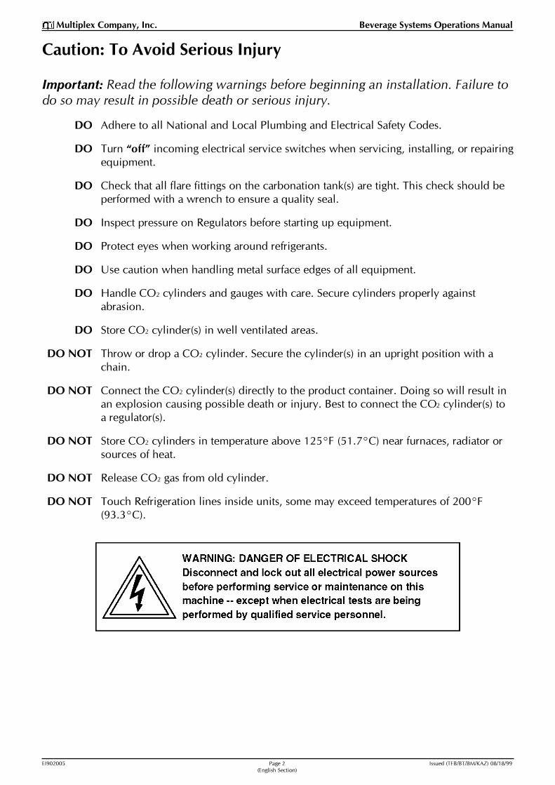
Caution: To Avoid Serious Injury
Important: Read the following warnings before beginning an installation. Failure todo so may result in possible death or serious injury.
DO Adhere to all National and Local Plumbing and Electrical Safety Codes.
DO Turn �off� incoming electrical service switches when servicing, installing, or repairingequipment.
DO Check that all flare fittings on the carbonation tank(s) are tight. This check should beperformed with a wrench to ensure a quality seal.
DO Inspect pressure on Regulators before starting up equipment.
DO Protect eyes when working around refrigerants.
DO Use caution when handling metal surface edges of all equipment.
DO Handle CO2 cylinders and gauges with care. Secure cylinders properly againstabrasion.
DO Store CO2 cylinder(s) in well ventilated areas.
DO NOT Throw or drop a CO2 cylinder. Secure the cylinder(s) in an upright position with achain.
DO NOT Connect the CO2 cylinder(s) directly to the product container. Doing so will result inan explosion causing possible death or injury. Best to connect the CO2 cylinder(s) toa regulator(s).
DO NOT Store CO2 cylinders in temperature above 125°F (51.7°C) near furnaces, radiator orsources of heat.
DO NOT Release CO2 gas from old cylinder.
DO NOT Touch Refrigeration lines inside units, some may exceed temperatures of 200°F(93.3°C).

EI902005 Page 3 Issued (TFB/BT/BM/KAZ) 08/18/99(English Section)
Multiplex Company, Inc. Beverage Systems Operations Manual
IntroductionThe Multiplex MV2000 Beverage System is a compact rackstorage system. This rack system provides storage for eight(8) Bag-In-Box complete with Beverage Pumps andChange-over Valves. The other standard components pro-vided with this stand include a Water Accumulator Tankand a CO2 Supply Control Panel. The Water AccumulatorTank maintains a constant water pressure to the system.The CO2 Supply Control Panel provides a regulated CO2
supply to the Beverage Pumps as well as to the Soda Fac-tory.
The accessories for the MV2000 Beverage System includean Air Compressor, a Water Booster Pump, a Water FilterPackage, and a CO2 Tank Bracket. This Stand is designed tomount most of the components directly to the stand. Theaccessories may be mounted to a wall if the store layoutrequires.
Unpacking the support stand and its components1. Carefully remove the packaging material from the stand
Be careful not to discard any components when dis-posing of the carton.
2. Remove all of the components packed inside the stand(Drip Pan, Accumulator Tank Kit, CO2 Control Panel,Water Booster, and all of the installation hardware).
3. Remove the upper Bag-In-Box rack from the inside ofthe lower stand (refer to figure 1). Remove the lowershelf.
Setting-up the support stand1. Place the upper rack on top of the lower stand. Align
the slots on both the Stand and Rack.
2. Locate the four (4) 1/4"-20 x 3/4" Hex Head screw andLocking Nuts supplied in the bag of hardware. Bolt theUpper Rack to the Lower Stand with the bolts and nuts.
Note: Do not tighten until the rack and stand are aligned.
3. Locate the upper rack with the back side of the rackand stand flush. Tighten the bolts.
4. Position the Drip Pan in between the side channels ofthe lower stand.
5. Roll the Roll-out Tray away from the support stand. Todo so, pull the rod on each side of the tray�s front untila threaded hole is visible just behind the front legs oneach side (refer to figure 1).
6. Locate the two (2) 1/4"-20 x 1 1/2" Long Bolts, 1/4"-20nuts, and split lock washers. Thread one (1) nut ontoeach bolt, then insert a bolt each into the threaded holes.The bolts should stop the tray�s forward motion (referto figure 1, Detail A).
7. Place the assembled stand into the desired location.Level the stand by adjusting the feet�s level bolts lo-cated on all four (4) legs. Replace the lower shelf to it�soriginal location.
8. The stand is now ready to install the Multiplex Refrig-eration Unit and any standard accessories.
Support Stand Set-up
Figure 1
Un-packing the Support Stand
Lower Stand
Refrigeration UnitRoll-out Tray
Upper Rack forBag-In-Box Storage
Lower Shelf
1/4"-20 x 7/8"Hex Headscrew
1/4"-20 Stainless SteelLocking Nuts
Drip PanUpper Rack
Note: Secure the top rack to thelower stand with four (4) HexHead screws and Locking Nuts.
Lower Stand
Refrigeration UnitRoll-out Tray
Detail A: Tray Stop
1 1/2"Long Bolt
HexNut
LockWasher
Lower Stand Leg
Roll-out Tray

Multiplex Company, Inc. Beverage Systems Operations Manual
EI902005 Page 4 Issued (TFB/BT/BM/KAZ) 08/18/99(English Section)
Water Accumulator Tank Kit
Figure 2
Mounting the Standard AccessoriesAccumulator Tank Kit (refer to figure 2)1. Locate the kit packaged with the stand. Remove all of
the components from the carton. Locate the fitting as-sembly and thread the fitting onto the tank.
Note: Use thread sealant to avoid leaks.
2. Identify the four (4) mounting holes located on the topof the Upper Rack.
3. Mount the four (4) straps using the four (4) #10-32 screwsand nuts supplied in the kit.
4. Place the Accumulator Tank with the fittings facing therear of the stand and towards the side in which thefilter will be mounted to. Form the straps to match theradius of the tank.
5. Bolt the two (2) strap sets together using the two (2)1/4"-20 screws and nuts (refer to figure 2).
CO2 Control Panel (refer to figure 3)The CO2 Control Panel may be mounted on either side ofthe stand or on the wall adjacent to the stand (not shown).
1. Locate the CO2 Control Panel also packed with the standand remove all components from the carton.
2. Determine on the stand the location of the Filter Pack-age and the CO2 Control Panel.
3. Locate the two (2) mounting holes on the side of thetop of the Rack.
4. Mount the CO2 Control Panel using these two (2) holeswith the two (2) 1/4"-20 x 3/4" Long Screws and 1/4"-20nuts provided with the stand installation kit.
5. Locate the lower hold-down Angle and two (2)#10-32 x 1/2" Long Screws.
6. Attach the Angle to the backside of the Panel withscrews from the front side.
Note: Rotate the gauges so they are visible from the front.Turn gauges clockwise to tighten the threads to avoid anyleaks.
Water Filter Package (refer to figure 3)1. Remove the Filter Package from the carton and locate
the mounting hardware.
Note: Mount the Filter Package on either the right or leftside of the stand. However, the left side is the recommendedside.
2. Locate the mounting slots on the lower stand legs. In-sert the 1/4"-20 x 7/8" Long Screws from the inside of theleg. Attach the 1/4"-20 Cap Nuts on the outside.
Note: Do not tighten these bolts completely (refer to fig-ure 3).
3. Position the Filter Panel on the bolts through the key-hole slots on the panel. Tighten the nuts completely.
CO2 Tank Bracket1. Unpack the kit. Identify the Tank bracket and the mount-
ing hardware supplied with the kit. (The optional mount-ing brackets supplied with the kit are not used for theMV2000 Stand.)
2. Determine the side for the CO2 tanks. Identify the slotson the upper rack for mounting.
Note: The tank bracket will clear the Filter Package so thetank(s) may be on the same side as the Filter Package.
3. Attach the bracket to the legs of the stand with the1/2"-20 x 1/2" Hex Head Bolts and 1/4"-20 Cap Nuts.
Note: Insert Bolts from the inside of the leg and use theCap Nut on the outside of the leg. This must be done so theremovable shelf can be removed.
4. Tighten all nuts completely.
Upper RackTop Plate
Thread fitting assembly onto the tank. Direct thefittings towards the location of the Water Filter.
#10-32 Mounting Screws and Nuts(four [4] required)
Tank Strap Hold Down(forms to the tank�s diameter)

EI902005 Page 5 Issued (TFB/BT/BM/KAZ) 08/18/99(English Section)
Multiplex Company, Inc. Beverage Systems Operations Manual
Figure 3
CO2 Control Panel Mounting with Rack Style Water Filter Package
Procedure for mounting the refrigerationunit to the support stand (refer to figure 4)1. Roll the Unit Tray out and block the front wheels while
placing the Refrigeration Unit onto the tray.
2. Place the unit on the tray towards the front and all theway to the right (refer to figure 4).
3. From under the tray, align the two (2) holes up with thebolt holes of the unit. Bolt the unit down using the boltsupplied with the Refrigeration Unit installation kit.
4. Complete the remaining installation as stated in theinstallation instructions provided with the unit.
Note: Additional instructions for routing the supply linesare covered later in this publication. When connecting theunit to the incoming power source, note that the unit willneed to be able to move forward approximately 30". Whenthe remote condenser unit is used, a minimum of two (2)24" diameter coils must be used at the rear of the refrig-eration unit to also allow it to be rolled out.
Mounting the optional accessoriesNote: All accessories may not be required for all installa-tions.
Water Booster Pump Assembly (refer to figure 5)The Multiplex Model WBK10 Water Booster mounts onthe top right side of the upper rack.
1. Remove the Water Booster Pump from the carton.
2. Locate the mounting bracket supplied with the BoosterAssembly. Attach the bracket to the rear of the top withraised lip towards the back of the stand. Fasten it withtwo (2) 1/4"-20 x 3/4" Long Screws and 1/4"-20 nuts pro-vided with the stand installation kit (refer to figure 5,Detail A).
3. Place the Water Booster Pump Assembly on the topover the bracket. Slide the assembly forward to allowthe rear of the panel to slip under the mounting bracket.
4. Attach the front of the panel to the top with two (2)1/4"-20 x 3/4" Long Screws and 1/4"-20 nuts provided withthe stand installation kit.
AngleCO2 Control PanelMounting Bracket
CO2 ControlPanel
Mounting Screwsand Nuts
(supplied with theSupport Stand)
Water FilterSystem
Mounting Screwsand Nuts
(supplied with theSupport Stand)
Figure 3A
Mounting Screwsand Nuts
(supplied with theSupport Stand)
CO2 Tank HoldDown Bracket

Multiplex Company, Inc. Beverage Systems Operations Manual
EI902005 Page 6 Issued (TFB/BT/BM/KAZ) 08/18/99(English Section)
Figure 5
Water Booster Pump Assembly
Mounting the Refrigeration Unit to the Support Stand
Figure 4
Air Compressor Assembly (refer to figure 5)The Air Compressor mounts to the top of the upper rack onthe left side.
1. Remove the Air Compressor from the carton and re-move the assembly from the shipping board.
2. Locate the four (4) mounting holes in the top and posi-tion the Air Compressor in place. Attach the Air Com-pressor using the hardware suppled with the Air Com-pressor.
3. Make the electrical connections to the compressor perthe instructions provided with the Air Compressor.
Accessories Switch Box (refer to figure 5)1. Locate the Switch Control Box and the two (2) mount-
ing screws.
2. Mount the Control Box with the switches facing towardthe front with the two (2) mounting screws from thebottom side of the top.
3. Refer to figure 6 �Accessory Switch Control Box Wir-ing Diagram� for component wiring connections.
Block Wheels(prevents tray from rollingwhile placing unit on tray) Unit Mounting Bolts
(supplied with unit)
Refrigeration Unit
Detail A
Use these mounting holes
OptionalAir Compressor
Water BoosterMounting Screws
and Nuts(supplied with the
Water Booster)
Water BoosterMounting Bracket(supplied with the
Water Booster)(refer to Detail A)
Top Plate of the UpperBag-In-Box Rack
Model WBK10Water Booster System
Switch Control BoxMounting Screws
(supplied with Control Box)
Accessories SwitchControl Box

EI902005 Page 7 Issued (TFB/BT/BM/KAZ) 08/18/99(English Section)
Multiplex Company, Inc. Beverage Systems Operations Manual
Figure 6
Accessory Switch Control Box Wiring Diagram
Procedure for connecting the watersupply to the equipment package(refer to the Water Circuit Diagram)1. Identify the Main Water Supply. The supply should com-
ply with all local plumbing codes and be equipped witha Manual Shut-off Valve.
2. Locate the 1/2" ID blue poly tubing supplied with theFilter Package.
3. Connect one (1) end of the tube to the Water Supplyand the other end to the Filter Package Inlet per thefilter installation instructions.
3. Route another piece of tubing out of the Filter PackageOutlet to the Accumulator Tank up the side of the standand over the top to the tank.
Note: If the optional Booster Pump is required, connect itbetween the Course Filter and the Fine Filter. Refer to theBooster Pump installation instructions for the correct con-nection method.
4. Route all tubing up the side of the stand and over thetop to the Booster Pump.
5. Connect the tube per the installation instructions pro-vided with the Filter Package. Route another piece oftubing from the Accumulator tank to the Water Regula-tor located on the CO2 Control Panel.
6. Connect the tube per the installation instructions sup-plied with the CO2 Control Panel.
7. Locate the Inlet water line supplied on the Refrigera-tion Unit. Route the line out the conduit opening andup to the CO2 Control Panel Water supply to the Re-frigeration unit.
Note: Loop the line towards the unit tray to allow the unitto moved in and out for service.
8. Connect the line per the installation instructions pro-vided with the Refrigeration Unit.
How to connect the CO2 (Air) supply tothe equipment package1. Identify the CO2 Supply source. Route a line to the CO2
Control Panel and connect it to the manifold on theCO2 Control Panel per the installation instructions.
Note: If CO2 Tank Kit is required, attach the RegulatorManifold Assembly to the tank(s). Route the line to the CO2
Control Panel per the installation instructions.
2. If the Optional Air Compressor Kit is required, routethe outlet line from the Air Compressor through theCO2 Control Panel and connect per the Installation in-structions.
3. Uncoil the line located on the last pump on the Bag-In-Box Pump Panel.
Connect theCO2 Alarm here
Connect theAir Compressor here
Air Compressor CO2 Alarm Water Booster
220 VAC, 50 Hz
Multiplex Company, Inc. Beverage Systems Operations Manual
EI902005 Page 8 Issued (TFB/BT/BM/KAZ) 08/18/99(English Section)
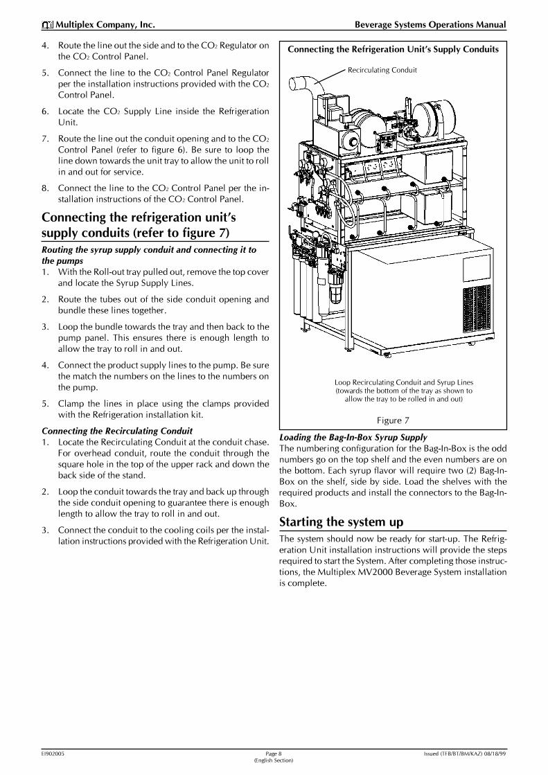
Connecting the Refrigeration Unit�s Supply Conduits
Figure 7
4. Route the line out the side and to the CO2 Regulator onthe CO2 Control Panel.
5. Connect the line to the CO2 Control Panel Regulatorper the installation instructions provided with the CO2
Control Panel.
6. Locate the CO2 Supply Line inside the RefrigerationUnit.
7. Route the line out the conduit opening and to the CO2
Control Panel (refer to figure 6). Be sure to loop theline down towards the unit tray to allow the unit to rollin and out for service.
8. Connect the line to the CO2 Control Panel per the in-stallation instructions of the CO2 Control Panel.
Connecting the refrigeration unit�ssupply conduits (refer to figure 7)Routing the syrup supply conduit and connecting it tothe pumps1. With the Roll-out tray pulled out, remove the top cover
and locate the Syrup Supply Lines.
2. Route the tubes out of the side conduit opening andbundle these lines together.
3. Loop the bundle towards the tray and then back to thepump panel. This ensures there is enough length toallow the tray to roll in and out.
4. Connect the product supply lines to the pump. Be surethe match the numbers on the lines to the numbers onthe pump.
5. Clamp the lines in place using the clamps providedwith the Refrigeration installation kit.
Connecting the Recirculating Conduit1. Locate the Recirculating Conduit at the conduit chase.
For overhead conduit, route the conduit through thesquare hole in the top of the upper rack and down theback side of the stand.
2. Loop the conduit towards the tray and back up throughthe side conduit opening to guarantee there is enoughlength to allow the tray to roll in and out.
3. Connect the conduit to the cooling coils per the instal-lation instructions provided with the Refrigeration Unit.
Loading the Bag-In-Box Syrup SupplyThe numbering configuration for the Bag-In-Box is the oddnumbers go on the top shelf and the even numbers are onthe bottom. Each syrup flavor will require two (2) Bag-In-Box on the shelf, side by side. Load the shelves with therequired products and install the connectors to the Bag-In-Box.
Starting the system upThe system should now be ready for start-up. The Refrig-eration Unit installation instructions will provide the stepsrequired to start the System. After completing those instruc-tions, the Multiplex MV2000 Beverage System installationis complete.
Recirculating Conduit
Loop Recirculating Conduit and Syrup Lines(towards the bottom of the tray as shown to
allow the tray to be rolled in and out)

EI902005 Page 9 Issued (TFB/BT/BM/KAZ) 08/18/99(English Section)
Multiplex Company, Inc. Beverage Systems Operations Manual
Model MV2000 Water Circuit Diagram


Instructions de Montage pour Appareil deBoissons Multiplex pour le
Distributeur de BoissonsModèle MV2000
French Section

EI902005 Page 12 Issued (TFB/BT/BM/KAZ) 08/18/99(French Section)
Multiplex Company, Inc. Beverage Systems Operations Manual
Avertissement : Pour éviter de graves accidents
Important : Lisez les avertissements suivants avant de débuter l�installation afind�éviter tout risque d�accident grave ou de danger de mort.
RESPECTEZ tous les Codes de Sécurité de Plomberie et Electriques,Nationaux et Locaux.
PLACEZ tous les interrupteurs électriques sur la position « arrêt » pendantl�entretien, l�installation et la réparation de l�appareil.
VERIFIEZ que tous les raccords coniques sur le (les) réservoir (s) decarbonatation sont bien étanches. Utilisez une clé lors ducontrôle pour obtenir des joints de bonne qualité.
CONTROLEZ la pression des Régulateurs avant la mise en route de l�appareil.
PROTEGEZ-VOUS les yeux lorsque vous travaillez à proximité des réfrigérants.
SOYEZ TOUJOURS PRUDENT lorsque vous manipulez les bords des surfaces métalliques del�appareil.
MANIPULEZ les bouteilles de CO2 et les indicateurs avec soin. Protégez lesbouteilles contre l�abrasion.
STOCKEZ la (les) bouteille (s) de CO2 dans des endroits bien ventilés.
NE JETEZ PAS et ne pas laissez tomber une bouteille de CO2. Maintenez la (les)bouteille (s) en position debout à l�aide d�une chaîne.
NE RACCORDEZ PAS la (les) bouteille (s) de CO2 directement au récipient de produit.Cela peut provoquer une explosion et tuer ou blesser quelqu�un.La (les) bouteille (s) doivent d�abord être raccordées à un (des)régulateur (s).
NE STOCKEZ PAS les bouteilles de CO2 près de fourneaux, de radiateurs ou desources de chaleur où la température est supérieure à 125°F(51,7° C).
NE TENTEZ PAS DE VIDER le gaz CO2 d�une bouteille usagée.
NE TOUCHEZ PAS les Conduites de Réfrigération situées à l�intérieur des unités.Leur température peut parfois dépasser 200°F (93,3°C).

EI902005 Page 13 Issued (TFB/BT/BM/KAZ) 08/18/99(French Section)
Multiplex Company, Inc. Beverage Systems Operations Manual
Montage Du Comptoir
Figure 1
Déballage du ComptoirIntroductionLe Distributeur de Boissons Multiplex MV2000 est unsystème de stockage compact en rack. Ce système en rackpermet de stocker huit (8) cubitainers avec les Pompes àBoissons et les Vannes d�Inversion. Les autres composantsstandard fournis avec ce Comptoir sont notamment unRéservoir d�Emmagasinage d�Eau et un Panneau deCommande d�Alimentation en CO2. Le Réservoird�Emmagasinage d�Eau maintient une pression d�eauconstante dans le système. Le Panneau de Commanded�Alimentation en CO2 régule l�alimentation en CO2 desPompes à Boissons et de la Fabrique de Soude.
Le Distributeur de Boissons MV2000 est fourni avec unCompresseur d�Air, une Pompe de Surpresseur d�Eau, unDispositif de Filtration d�Eau et un Support de Réservoir deCO2. La plupart des composants peuvent être montésdirectement sur le Comptoir. Les accessoires peuvent êtreinstallés sur un mur si la disposition du magasin l�exige.
Déballage du Comptoir et de ses composants1. Retirez soigneusement les matériaux d�emballage du
Comptoir. Vérifiez qu�aucun composant n�a été oubliédans le carton avant de le jeter.
2. Retirez tous les composants emballés à l�intérieur duComptoir (Collecteur de Condensat, Kit du Réservoird�Emmagasinage, Panneau de Commande de CO2,Surpresseur d�Eau et tous les éléments de montage).
3. Retirez le rack supérieur de Cubitainers de l�intérieurdu Comptoir inférieur (voir figure 1). Retirez l�étagèreinférieure.
Installation du Comptoir1. Placez le rack supérieur sur le Comptoir inférieur.
Utilisez les fentes pour les aligner.
2. Repérez les quatre (4) Vis à Tête Hexagonale et Ecrousde Blocage 1/4"-20 x 3/4" fournis dans le sac de visserie.Fixez le Rack Supérieur sur le Comptoir Inférieur à l�aidedes boulons et des écrous.
Remarque: Ne serrez pas avant d�avoir aligné le Rack et leComptoir.
3. Repérez l�endroit où l�arrière du Rack supérieur et leComptoir se touchent. Serrez les boulons.
4. Installez le Collecteur de Condensat entre les profiléslatéraux du Comptoir inférieur.
5. Sortez le Plateau Roulant du Comptoir. Pour cela, tirezsur la tige située de chaque côté de l�avant du plateaujusqu�à ce qu�un trou taraudé apparaisse juste derrièreles pieds avant de chaque côté (voir figure 1).
6. Repérez les deux (2) Grands Boulons 1/4"-20 x 1 1/2",les écrous 1/4"-20 et les rondelles de blocage fendues.Installez un (1) écrou sur chaque boulon, puisintroduisez les boulons dans les trous taraudés. Lesboulons doivent stopper le mouvement en avant duplateau (voir figure 1, Détail A).
Vis à tête hexagonale1/4"-20 x 7/8"
Ecrous de blocage 1/4"-20en Acier Inoxydable
Collecteur deCondensatRack Supérieur
Remarque: Fixez le racksupérieur sur le Comptoirinférieur à l�aide des quatre(4) Vis à tête hexagonale etEcrous de blocage.
Comptoir Inférieur
Plateau Roulant duDispositif de Réfrigération
Détail A: Arrêt du Plateau
GrandBoulon 1 1/2"
Ecrouhexagonal
RondelleFrein
Pied du Comptoir Inférieur
Plateau Roulant
Comptoir Inférieur
Plateau Roulant duDispositif deRéfrigération
Rack Supérieurpour Stockage des
Cubitainers
EtagèreInférieure
7. Installez le Comptoir assemblé à l�endroit souhaité.Réglez la hauteur du Comptoir à l�aide des boulons deréglage situés sur les quatre (4) pieds. Réinstallezl�étagère inférieure dans sa position d�origine.
8. Le Dispositif de Réfrigération Multiplex et lesaccessoires standard peuvent à présent être installés surle Comptoir.

EI902005 Page 14 Issued (TFB/BT/BM/KAZ) 08/18/99(French Section)
Multiplex Company, Inc. Beverage Systems Operations Manual
kit du Réservoir d�Emmagasinage d�Eau
Figure 2
Montage des Accessoires StandardKit du Réservoir d�Emmagasinage (voir figure 2)1. Repérez le kit emballé avec le Comptoir. Retirez tous
les composants du carton. Repérez les éléments demontage et installez-les sur le réservoir.
Remarque: Utilisez du mastic d�étanchéité pour éviter lesfuites.
2. Repérez les quatre (4) trous de montage sur le dessusdu Rack Supérieur.
3. Installez les quatre (4) sangles à l�aide des quatre (4) viset écrous #10-32 fournis avec le kit.
4. Installez le Réservoir d�Emmagasinage avec les fixationsface à l�arrière du Comptoir et du côté où le filtre serainstallé. Réglez les sangles en fonction de la positiondu réservoir.
5. Vissez les deux (2) jeux de sangles ensemble à l�aidedes deux (2) vis et écrous 1/4"-20 (voir figure 2).
Panneau de Commande de CO2 (voir figure 3)Le Panneau de Commande de CO2 peut être monté d�uncôté ou de l�autre du Comptoir ou sur le mur adjacent auComptoir (non représenté).
1. Repérez le Panneau de Commande de CO2 égalementemballé avec le Comptoir et retirez tous les composantsdu carton.
2. Déterminez sur le Comptoir l�emplacement duDispositif de Filtration et du Panneau de Commandede CO2.
3. Repérez les deux (2) trous de montage en haut du Rack,sur le côté.
4. Installez le Panneau de Commande de CO2 en utilisantces deux (2) trous et à l�aide des deux (2) Grandes Vis1/4"-20 x 3/4" et des écrous 1/4"-20 fournis dans le kit demontage du Comptoir.
5. Repérez l�Angle de retenue inférieur et deux (2) GrandesVis #10-32 x 1/2".
6. Fixez l�Angle à l�arrière du Panneau à l�aide des vis dela face avant.
Remarque: Tournez les indicateurs de façon à ce qu�ilssoient visibles de l�avant. Tournez-les dans le sens horairepour serrer les filetages et empêcher les fuites.
Dispositif de Filtration d�Eau (voir figure 3)1. Retirez le Dispositif de Filtration du carton et repérez
les éléments de montage.
Remarque : Vous pouvez installer le Dispositif de Filtra-tion sur le côté droit ou gauche du Comptoir. Il est toutefoisconseillé de choisir le côté gauche.
2. Repérez les fentes de montage sur les pieds du Comptoirinférieur. Introduisez les Grandes Vis 1/4"-20 x 7/8" àl�intérieur du pied. Fixez les Ecrous Borgnes 1/4"-20 àl�extérieur.
Remarque: Ne serrez pas complètement ces boulons (voirfigure 3).
3. Positionnez le Panneau Filtrant sur les boulons à l�aidedes fentes en trou de serrure du panneau. Serrez lesécrous complètement.
Support de Réservoir de CO2
1. Déballez le kit. Repérez le Support de Réservoir et leséléments de montage livrés avec le kit. (Les supportsde montage optionnels fournis avec le kit ne sont pasutilisés avec le Comptoir MV2000.)
2. Déterminez de quel côté seront placés les Réservoirsde CO2. Repérez les fentes de montage sur le Racksupérieur.
Remarque: Le support du réservoir cachera le Dispositif deFiltration ; le (les) réservoir(s) peut (peuvent) donc être dumême côté que le Dispositif de Filtration.
Plaque Supérieure duRack Supérieur
Installez les éléments de montage sur le réservoir.Orientez les fixationsvers l�emplacement du Filtre d�Eau.
Vis et Ecrous de Montage #10-32(quatre [4])
Butée d�ancrage de Sangle du réservoir(forme le diamètre du réservoir)

EI902005 Page 15 Issued (TFB/BT/BM/KAZ) 08/18/99(French Section)
Multiplex Company, Inc. Beverage Systems Operations Manual
Figure 3
Montage du Panneau de Commande de CO2 avec Dispositif de Filtration d�Eau en Rack
3. Fixez le support sur les pieds du Comptoir à l�aide desBoulons à Tête Hexagonale 1/2"-20 x 1/2" et des EcrousBorgnes 1/4"-20.
Remarque: Introduisez les Boulons à l�intérieur du pied etutilisez un Ecrou Borgne à l�extérieur du pied. Cela permetde retirer l�étagère amovible.
4. Serrez complètement tous les écrous.
Procédure de montage du dispositif deréfrigération sur le Comptoir(voir figure 4)1. Sortez le Bloc Plateau et bloquez les roues avant pen-
dant que vous installez le Dispositif de Réfrigérationsur le plateau.
2. Placez le dispositif sur le plateau, vers l�avant et à droite(voir figure 4).
3. Alignez les deux (2) trous sous le plateau avec les trousde boulon du dispositif. Fixez le dispositif à l�aide desboulons fournis dans le kit de montage du Dispositif deréfrigération.
4. Terminez l�installation conformément aux instructionsde montage fournies avec le dispositif.
Remarque : Des instructions supplémentaires concernantl�installation des conduites d�alimentation sont fournies plusloin. Pour pouvoir être raccordé à une source d�alimentationélectrique, le dispositif devra pouvoir s�avancer d�environ30". Si le groupe compresseur-condensateur séparé estutilisé, au moins deux (2) bobines de diamètre 24" serontégalement nécessaires à l�arrière du dispositif deréfrigération pour pouvoir l�avancer.
Montage des accessoires optionnelsRemarque: Tous les accessoires ne seront peut-être pas né-cessaires pour l�installation.
Groupe Pompe de Surpresseur d�Eau (voir figure 5)Le Surpresseur d�Eau Multiplex Modèle WBK10 s�installesur le côté supérieur droit du Rack supérieur.
1. Retirez la Pompe de Surpresseur d�Eau du carton.
2. Repérez le support de montage fourni avec le Groupede Surpression. Fixez le support en haut à l�arrière, avecla lèvre remontée tournée vers l�arrière du Comptoir.Fixez-le à l�aide de deux (2) Grandes Vis 1/4"-20 x 3/4"et des écrous 1/4"-20 fournis avec le kit de montage duComptoir (voir figure 5, Détail A).
AngleCO2 Control PanelMounting Bracket
Panneau deCommande de CO2
Vis et Ecrous deMontage
(fournis avec leComptoir)
Système deFiltration d�Eau
Vis et Ecrous deMontage
(fournis avec leComptoir)
Figure 3A
Vis et Ecrous deMontage
(fournis avec leComptoir)
CO2 Tank HoldDown Bracket
EI902005 Page 16 Issued (TFB/BT/BM/KAZ) 08/18/99(French Section)
Multiplex Company, Inc. Beverage Systems Operations Manual
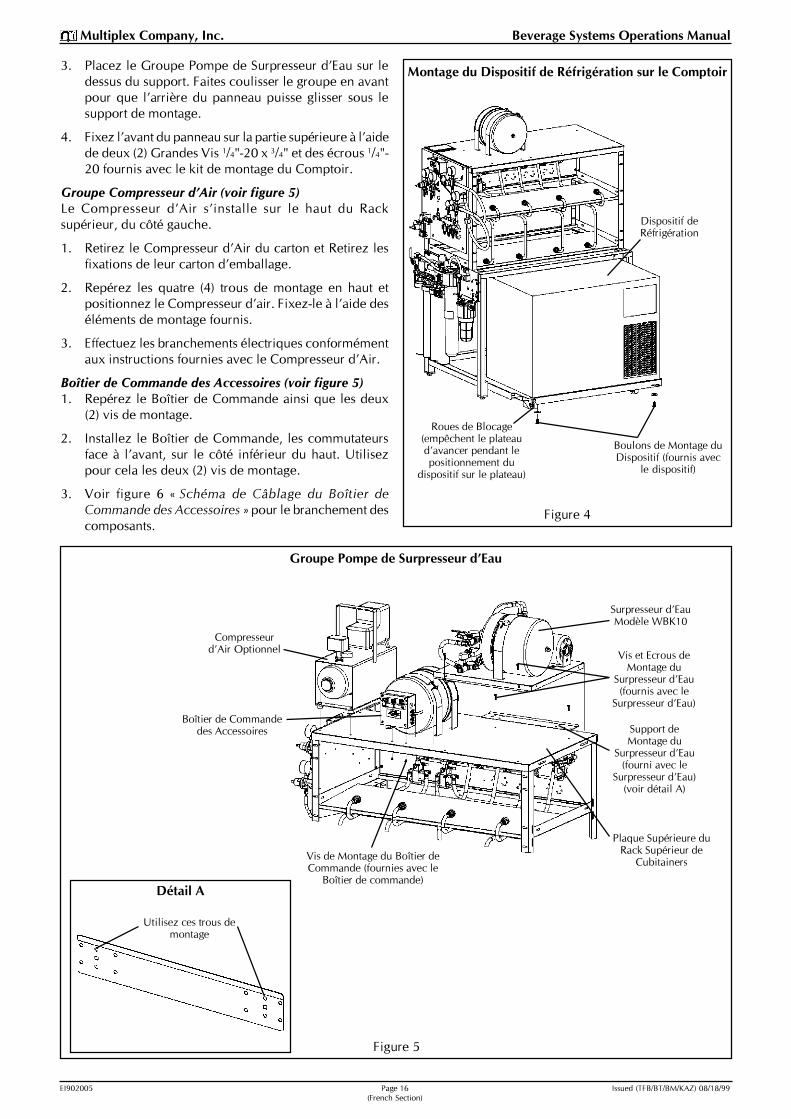
Montage du Dispositif de Réfrigération sur le Comptoir
Figure 4
Figure 5
Groupe Pompe de Surpresseur d�Eau
3. Placez le Groupe Pompe de Surpresseur d�Eau sur ledessus du support. Faites coulisser le groupe en avantpour que l�arrière du panneau puisse glisser sous lesupport de montage.
4. Fixez l�avant du panneau sur la partie supérieure à l�aidede deux (2) Grandes Vis 1/4"-20 x 3/4" et des écrous 1/4"-20 fournis avec le kit de montage du Comptoir.
Groupe Compresseur d�Air (voir figure 5)Le Compresseur d�Air s�installe sur le haut du Racksupérieur, du côté gauche.
1. Retirez le Compresseur d�Air du carton et Retirez lesfixations de leur carton d�emballage.
2. Repérez les quatre (4) trous de montage en haut etpositionnez le Compresseur d�air. Fixez-le à l�aide deséléments de montage fournis.
3. Effectuez les branchements électriques conformémentaux instructions fournies avec le Compresseur d�Air.
Boîtier de Commande des Accessoires (voir figure 5)1. Repérez le Boîtier de Commande ainsi que les deux
(2) vis de montage.
2. Installez le Boîtier de Commande, les commutateursface à l�avant, sur le côté inférieur du haut. Utilisezpour cela les deux (2) vis de montage.
3. Voir figure 6 « Schéma de Câblage du Boîtier deCommande des Accessoires » pour le branchement descomposants.
Roues de Blocage(empêchent le plateaud�avancer pendant lepositionnement du
dispositif sur le plateau)
Boulons de Montage duDispositif (fournis avec
le dispositif)
Dispositif deRéfrigération
Détail A
Utilisez ces trous demontage
Compresseurd�Air Optionnel Vis et Ecrous de
Montage duSurpresseur d�Eau(fournis avec le
Surpresseur d�Eau)
Support deMontage du
Surpresseur d�Eau(fourni avec le
Surpresseur d�Eau)(voir détail A)
Plaque Supérieure duRack Supérieur de
Cubitainers
Surpresseur d�EauModèle WBK10
Vis de Montage du Boîtier deCommande (fournies avec le
Boîtier de commande)
Boîtier de Commandedes Accessoires
EI902005 Page 17 Issued (TFB/BT/BM/KAZ) 08/18/99(French Section)
Multiplex Company, Inc. Beverage Systems Operations Manual
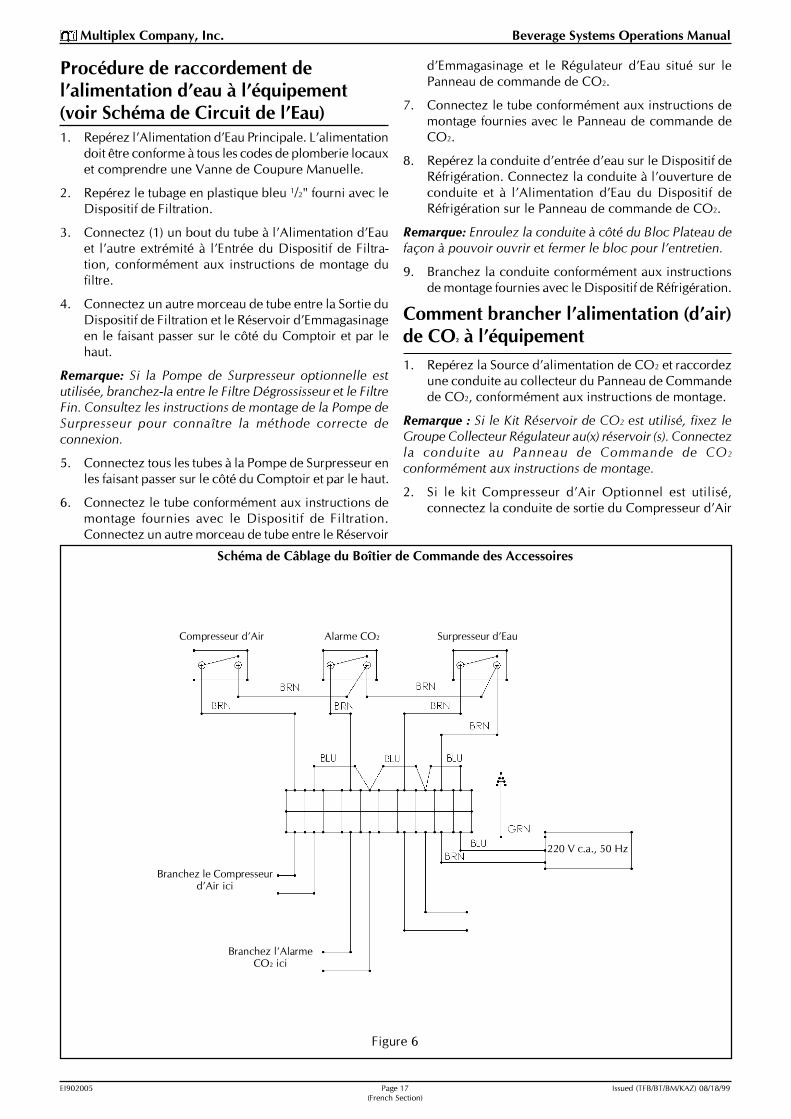
Figure 6
Schéma de Câblage du Boîtier de Commande des Accessoires
Branchez l�AlarmeCO2 ici
Branchez le Compresseurd�Air ici
Compresseur d�Air Alarme CO2 Surpresseur d�Eau
220 V c.a., 50 Hz
Procédure de raccordement del�alimentation d�eau à l�équipement(voir Schéma de Circuit de l�Eau)1. Repérez l�Alimentation d�Eau Principale. L�alimentation
doit être conforme à tous les codes de plomberie locauxet comprendre une Vanne de Coupure Manuelle.
2. Repérez le tubage en plastique bleu 1/2" fourni avec leDispositif de Filtration.
3. Connectez (1) un bout du tube à l�Alimentation d�Eauet l�autre extrémité à l�Entrée du Dispositif de Filtra-tion, conformément aux instructions de montage dufiltre.
4. Connectez un autre morceau de tube entre la Sortie duDispositif de Filtration et le Réservoir d�Emmagasinageen le faisant passer sur le côté du Comptoir et par lehaut.
Remarque: Si la Pompe de Surpresseur optionnelle estutilisée, branchez-la entre le Filtre Dégrossisseur et le FiltreFin. Consultez les instructions de montage de la Pompe deSurpresseur pour connaître la méthode correcte deconnexion.
5. Connectez tous les tubes à la Pompe de Surpresseur enles faisant passer sur le côté du Comptoir et par le haut.
6. Connectez le tube conformément aux instructions demontage fournies avec le Dispositif de Filtration.Connectez un autre morceau de tube entre le Réservoir
d�Emmagasinage et le Régulateur d�Eau situé sur lePanneau de commande de CO2.
7. Connectez le tube conformément aux instructions demontage fournies avec le Panneau de commande deCO2.
8. Repérez la conduite d�entrée d�eau sur le Dispositif deRéfrigération. Connectez la conduite à l�ouverture deconduite et à l�Alimentation d�Eau du Dispositif deRéfrigération sur le Panneau de commande de CO2.
Remarque: Enroulez la conduite à côté du Bloc Plateau defaçon à pouvoir ouvrir et fermer le bloc pour l�entretien.
9. Branchez la conduite conformément aux instructionsde montage fournies avec le Dispositif de Réfrigération.
Comment brancher l�alimentation (d�air)de CO2 à l�équipement1. Repérez la Source d�alimentation de CO2 et raccordez
une conduite au collecteur du Panneau de Commandede CO2, conformément aux instructions de montage.
Remarque : Si le Kit Réservoir de CO2 est utilisé, fixez leGroupe Collecteur Régulateur au(x) réservoir (s). Connectezla conduite au Panneau de Commande de CO2
conformément aux instructions de montage.
2. Si le kit Compresseur d�Air Optionnel est utilisé,connectez la conduite de sortie du Compresseur d�Air

EI902005 Page 18 Issued (TFB/BT/BM/KAZ) 08/18/99(French Section)
Multiplex Company, Inc. Beverage Systems Operations Manual
Branchement des Conduites d�Alimentation duDispositif de Réfrigération
Figure 7
dans le Panneau de Commande de CO2 conformémentaux instructions de montage.
3. Déroulez la conduite située sur la dernière pompe duPanneau de Pompes de Cubitainers.
4. Branchez la conduite sur le Régulateur de CO2 duPanneau de commande de CO2, en passant sur le côté.
5. Effectuez le branchement de la conduite sur leRégulateur du Panneau de commande de CO2
conformément aux instructions de montage fourniesavec le Panneau de commande de CO2.
6. Repérez la Conduite d�Alimentation de CO2 à l�intérieurdu Dispositif de Réfrigération.
7. Connectez la conduite à l�ouverture de conduite et auPanneau de Commande de CO2 (voir figure 6). Veillezà bien enrouler la conduite à côté du bloc plateau pourque ce dernier puisse être ouvert et refermé pourl�entretien.
8. Effectuez le raccordement de la conduite sur le Panneaude Commande de CO2 conformément aux instructionsde montage du Panneau de Commande de CO2.
Branchement des conduitesd�alimentation du dispositif deréfrigération (voir figure 7)Installation et raccordement aux pompes de la conduited�alimentation de sirop1. Ouvrez le plateau roulant puis retirez le couvercle
supérieur et repérez les Conduites d�Alimentation deSirop.
2. Connectez les tubes à l�ouverture de conduite latéralepuis attachez-les ensemble.
3. Enroulez-les à côté du plateau et du panneau despompes pour que la longueur soit suffisante pour ouvriret refermer le plateau.
4. Connectez les conduites d�alimentation de produit à lapompe. Veillez à bien respecter les numéros indiquéssur les conduites et sur la pompe.
5. Fixez les conduites à l�aide des fixations fournies dansle kit de montage de Réfrigération.
Branchement de la Conduite de Recirculation1. Repérez la Conduite de Recirculation sur le châssis de
conduite. Les conduites en hauteur doivent passer dansle trou carré en haut du Rack supérieur et descendreau dos du Comptoir.
2. Enroulez la conduite à côté du plateau et de l�ouverturede conduite latérale de façon à disposer d�une longueursuffisante pour ouvrir et fermer le plateau.
3. Connectez la conduite aux serpentins derefroidissement, conformément aux instructions demontage fournies avec le Dispositif de Réfrigération.
Chargement de l�alimentation en Sirop des cubitainersLe système de numérotation des cubitainers est le suivant :les numéros impairs vont sur l�étagère supérieure, lesnuméros pairs vont en bas. Il devra y avoir deux (2)Cubitainers côte à côte sur l�étagère pour chaque arôme desirop. Remplissez les étagères avec les produits souhaitéset installez les connecteurs des Cubitainers.
Mise en route du systèmeLe système est maintenant prêt à l�emploi. Les instructionsde montage du Dispositif de Réfrigération décrivent lesétapes à suivre pour la mise en route du Système. Une foisces instructions mises en pratique, l�installation duDistributeur de Boissons MV2000 Multiplex est terminée.
Conduite de Recirculation
Enroulez la Conduite de Recirculation et lesConduites de Sirop (à côté du plateau,
comme indiqué, pour permettre l�ouvertureet la fermeture du plateau)

EI902005 Page 19 Issued (TFB/BT/BM/KAZ) 08/18/99(French Section)
Multiplex Company, Inc. Beverage Systems Operations Manual
Schéma de Circuit de l�Eau du Modèle MV2000


Istruzioni per l�installazione di un distributoredi bevande Multiplex
Sistema di distribuzionebevande Modello MV2000
Italian Section
EI902005 Page 22 Issued (TFB/BT/BM/KAZ) 08/18/99(Italian Section)
Multiplex Company, Inc. Beverage Systems Operations Manual
Attenzione: per evitare lesioni gravi
Importante: Leggere le seguenti avvertenze prima di procedere con l�installazione.La mancata osservanza potrebbe portare a rischio di morte o di gravi lesioni.
DA FARE Rispettare tutte le normative nazionali e locali riguardo la sicurezza idraulica edelettrica.
DA FARE Mettere in posizione �off� (spento) tutti gli interruttori di servizio elettrici in entratamentre si eseguono lavori si assistenza, installazione o riparazione sull�apparecchio.
DA FARE Controllare che tutti gli innesti sul /sui serbatoio/i di carbonatazione siano a tenuta.Questo controllo va eseguito con l�aiuto di una chiave inglese, per garantire unavalida sigillatura.
DA FARE Verificare la pressione sui Regolatori prima di avviare l�apparecchio .
DA FARE Proteggere gli occhi mentre si eseguono lavori in prossimità di refrigeranti.
DA FARE Usare cautela quando si maneggiano i bordi delle superfici di metallodell�apparecchio.
DA FARE Maneggiare con cura le bombole e gli indicatori di livello di CO2. Assicurare
adeguatamente le bombole contro le abrasioni.
DA FARE Riporre le bombole di CO2 in zone ben ventilate.
NON Rovesciare o far cadere una bombola di CO2. Bloccare la bombola (bombole) in
posizione verticale per mezzo di una catena.
NON Collegare direttamente la/le bombola/e di CO2 al contenitore del prodotto. Tale
operazione porterebbe ad un�esplosione che potrebbe causare morti o feriti. E� piùopportuno collegare la/le bombola/e di CO
2 ad un regolatore (regolatori).
NON Riporre le bombole di CO2 in presenza di temperature superiori ai 125°F (51.7°C),
vicino a caldaie, caloriferi o fonti di calore.
NON Far fuoriuscire l�anidride carbonica da vecchie bombole.
NON Toccare le linee di refrigerazione all�interno degli apparecchi, alcune potrebberoavere temperature superiori ai 200°F (93.3°C).

EI902005 Page 23 Issued (TFB/BT/BM/KAZ) 08/18/99(Italian Section)
Multiplex Company, Inc. Beverage Systems Operations Manual
Allestimento banco di supporto
Figura 1
Disimballaggio del banco di supportoIntroduzioneIl Sistema di distribuzione bevande Multiplex MV2000 èun sistema compatto di distribuzione da banco. Il sistema èin grado di contenere fino a otto (8) Bag-in-Box complete dipompe di distribuzione bevande e valvole di conversione.Gli altri componenti standard forniti con il bancocomprendono un serbatoio di accumulo per l�acqua ed unpannello di controllo alimentazione CO2. Il serbatoio diaccumulo dell�acqua mantiene costante la pressionedell�acqua nel sistema. Il pannello di controlloalimentazione CO2.alimenta sia le pompe di distribuzionebevande sia l�unità di produzione della soda.
Gli accessori per il Sistema di distribuzione bevandeMV2000 comprendono un compressore d�aria, una pompadi sovralimentazione acqua, un�unità filtrante per l�acquaed un supporto per il serbatoio di CO2. Il banco è progettatoin modo da poter montare la maggior parte dei componentidirettamente sul banco stesso. Gli accessori possono esseremontati su di una parete se la configurazione lo richiede.
Disimballaggio del banco di supporto e dei suoicomponenti1. Rimuovere attentamente il materiale di imballaggio dal
banco. Prestare attenzione a non eliminare nessuno deicomponenti nel gettare via il cartone.
2. Togliere tutti i componenti imballati all�interno delbanco (cassetto raccoglicocce, kit di montaggioserbatoio di accumulo, pannello di controllo CO2,sovralimentatore dell�acqua, e tutti gli attrezzi perl�installazione).
3. Estrarre il supporto superiore con le Bag-in-Boxdall�interno del banco inferiore (vedi figura 1). Togliereil ripiano inferiore.
Allestimento del banco di supporto1. Posizionare il supporto superiore sopra il banco
inferiore. Allineare i fori del banco e del supporto.
2. Posizionare le quattro(4) viti esagonali 1/4"-20 x 3/4" e idadi di fissaggio forniti nella borsa degli attrezzi.Avvitare il supporto superiore al banco inferiore conbulloni e dadi.
Attenzione: Non chiudere completamente finché supportoe banco non sono allineati.
3. Mettere in posizione il supporto superiore con il latoposteriore e lo scarico del banco. Fissare i bulloni.
4. Collocare il cassetto raccogligocce tra i canali lateralidel supporto inferiore.
5. Estrarre il carrello estraibile dal banco di supporto. Perfare questo, tirare le aste su entrambi i lati della parteanteriore del carrello, fino a quando non è visibile unforo filettato appena dietro le gambe anteriori, suentrambi i lati (vedi figura 1).
6. Posizionare i due (2) bulloni lunghi 1/4"-20 x 1 1/2", idadi 1/4"-20, e le rondelle di fissaggio aperte. Avvitareun (1) dado su ogni bullone, quindi inserire un bullonein ogni foro filettato. I bulloni dovrebbero servire adarrestare il movimento in avanti del carrello (vedi figura1, particolare A).
7. Mettere il banco così montato nella posizionedesiderata. Mettere a livello il banco regolando i bulloniposti su tutte e quattro (4) le gambe. Riporre il ripianoinferiore nella sua posizione iniziale.
8. Il banco è ora pronto per l�installazione dell�unità direfrigerazione Multiplex e di tutti gli accessori standard.
Viti esagonali1/4"-20 x 7/8"
Dadi di bloccaggio inacciaio inossidabile 1/4" 20
Cassettoraccogli gocce
Supportosuperiore
Attenzione: fissare il supportosuperiore al banco inferiorecon quattro (4) viti esagonali edadi di bloccaggio.
Banco inferiore
Carrello estraibile perunità di refrigerazione
Particolare A: arresto carrello
Bullonelungo 1 1/2"
Dadoesagonale
Rondelle difissaggio
Gamba bancoinferiore
Carrello estraibile
Banco inferiore
Carrello estraibile per unitàdi refrigerazione
Supporto superioreper l�allineamento
di Bag-in-Box
Ripianoinferiore

EI902005 Page 24 Issued (TFB/BT/BM/KAZ) 08/18/99(Italian Section)
Multiplex Company, Inc. Beverage Systems Operations Manual
Kit serbatoio di accumulo acqua
Figura 2
Montaggio degli accessori standardKit di montaggio serbatoio di accumulo (vedi figura 2)1. Individuare il kit di montaggio imballato insieme al
banco. Togliere tutti i componenti dal cartone. Indivi-duare il gruppo di innesti ed avvitarli sul serbatoio.
Attenzione: Utilizzare del sigillante per filetti per evitareperdite.
2. Identificare i quattro (4) fori di montaggio posti sopra ilsupporto superiore.
3. Montare le quattro (4) staffe usando le quattro (4) viti#10-32 e i bulloni forniti con il kit.
4. Posizionare il serbatoio di accumulo con gli innestirivolti verso il retro del banco e verso il lato su cuiverrà montato il filtro. Disporre le staffe in modo checoincidano con il raggio del serbatoio.
5. Fissare insieme i due (2) gruppi di staffe usando le due(2) viti 1/4"-20 e i dadi (vedi figura 2).
Pannello di controllo CO2 (vedi figura 3)Il pannello di controllo CO2 può essere montato sia sulbanco, sia sulla parete adiacente il banco (variante nonillustrata).
1. Individuare il pannello di controllo CO2 fornito con ilbanco e togliere tutti i componenti dal cartone.
2. Definire sul banco la posizione per l�unità filtrante eper il pannello di controllo CO2.
3. Individuare i due (2) fori di montaggio sul lato superioredel supporto.
4. Montare il pannello di controllo CO2 usando questidue (2) fori per le due (2) viti 1/4"-20 x 3/4" e i dadi1/4"-20 forniti con il kit di installazione del banco.
5. Individuare il cantonale di fissaggio inferiore e due (2)viti lunghe #10-32 x 1/2".
6. Fissare il cantonale sul lato posteriore del pannello permezzo di viti passate dal lato anteriore.
Attenzione: Ruotare gli indicatori di livello in modo chesiano visibili dal davanti. Girare gli indicatori in senso orarioper chiuderli ed evitare qualsiasi perdita.
Unità filtrante per l�acqua (vedi figura 3)1. Togliere l�unità filtrante dal cartone e individuare gli
attrezzi per il montaggio.
Attenzione: L�unità filtrante può essere montata a sceltasul lato destro o su quello sinistro del banco. In ogni caso,si consiglia il lato sinistro.
2. Individuare i fori di montaggio sulle gambe del bancoinferiore. Inserite le viti lunghe 1/4"-20 x 7/8" dall�internodelle gambe. Avvitare i dadi ciechi 1/4"-20 all�esterno.
Attenzione: Non chiudere completamente questi bulloni(vedi figura 3).
3. Posizionare il pannello del filtro sui bulloni per mezzodei fori a serratura sul pannello. Chiuderecompletamente i dadi.
Supporto per serbatoio CO2
1. Disimballare il kit. Identificare il supporto per serbatoioe gli attrezzi di montaggio forniti con il kit. (I supportidi montaggio supplementari forniti con il kit non sonousati per il Banco MV2000.)
2. Determinare il lato per il serbatoio CO2. Identificare ifori per il montaggio sul supporto superiore.
Attenzione: Il supporto per il serbatoio lascia spazio perl�unità filtrante, in modo che il /i serbatoio/i possono esseresullo stesso lato su cui si trova l�unità filtrante..
3. Fissare il supporto alle gambe del banco con i bulloniesagonali 1/2"-20 x 1/2" e con i dadi ciechi 1/4"-20.
Attenzione: Inserire i bulloni dall�interno della gamba efissare i dadi ciechi all�esterno. Questo va fatto in modo dapoter rimuovere il ripiano estraibile.
4. Chiudere completamente tutti i dadi.
Piano superioresupporto superiore
Gruppo innesti filettati per il serbatoio. Direzionare gliinnesti verso la postazione del filtro per l�acqua.
Viti e dadi di montaggio #10-32(ne occorrono quattro (4) )
Staffa di fissaggio serbatoio(conforme al diametro serbatoio)

EI902005 Page 25 Issued (TFB/BT/BM/KAZ) 08/18/99(Italian Section)
Multiplex Company, Inc. Beverage Systems Operations Manual
Figura 3
Pannello di controllo CO2 montaggio con unità filtrante dell�acqua conforme al banco
Procedura per il montaggio dell�unità direfrigerazione sul banco di supporto(vedi figura 4)1. Estrarre il carrello dell�unità e bloccare le ruote anteriori
mentre viene posizionata l�unità di refrigerazione sulcarrello.
2. Posizionare l�unità sul carrello verso il lato anteriore eil più possibile a destra (vedi figura 4).
3. Da sotto il carrello, allineare i due (2) fori con i fori peri bulloni sull�unità. Avvitare l�unità al carrello usando ibulloni forniti con il kit di installazione dell�unità direfrigerazione.
4. Completare le restanti procedure di installazione comeindicato nelle istruzioni di installazione fornite conl�unità.
Attenzione: Ulteriori informazioni su come tracciare le lineedi alimentazione sono fornite più avanti in questo manuale.Quando si collega l�unità alla fonte di energia in entrata,prestare attenzione al fatto che l�unità dovrà potersi spostarein avanti di circa 30". Se si utilizza l�unità di condensazioneremota, occorre usare almeno due (2) serpentine da 24�
di diametro sul retro dell�unità di refrigerazione, per farein modo che la si possa estrarre.
Montaggio degli accessori supplementariAttenzione: Tutti questi accessori possono non esserenecessari per tutte le installazioni.
Gruppo pompa di sovralimentazione acqua(vedi figura 5)Il sovralimentatore d�acqua modello Multiplex WBK10viene montato in alto sul lato destro del supporto superiore.
1. Togliere la pompa di sovralimentazione acqua dalcartone.
2. Individuare il supporto di montaggio fornito con ilgruppo di sovralimentazione. Fissare il supporto al retrodella parte superiore con il bordo sollevato verso il retrodel banco. Fissarlo con due (2) viti lunghe 1/4"-20 x 3/4"e i dadi 1/4"-20 forniti con il kit di installazione del banco(vedi figura 5, particolare A).
3. Posizionare il gruppo pompa di sovralimentazioneacqua in alto sopra il supporto. Spingere in avanti ilgruppo per fare in modo che il retro del pannello siinfili sotto il supporto di montaggio.
AngleCO2 Control PanelMounting Bracket
Pannello dicontrollo CO2
Viti e dadi dimontaggio (forniti conil banco di supporto)
Sistema filtrantedell�acqua
Viti e dadi dimontaggio (forniti conil banco di supporto)
Figura 3A
Viti e dadi dimontaggio (forniti
con il banco disupporto)
CO2 Tank HoldDown Bracket

EI902005 Page 26 Issued (TFB/BT/BM/KAZ) 08/18/99(Italian Section)
Multiplex Company, Inc. Beverage Systems Operations Manual
Montaggio dell�unità di refrigerazione sul banco disupporto
Figura 4
Figura 5
Gruppo pompa di sovralimentazione acqua
4. Fissare la parte anteriore del pannello alla parte altacon due (2) viti lunghe 1/4"-20 x 3/4" e dadi 1/4"-20forniti con il kit di installazione del banco.
Gruppo compressore d�aria (vedi figura 5)Il compressore d�aria viene montato sopra il supportosuperiore, sul lato sinistro.
1. Togliere il compressore d�aria dal cartone e togliere ilgruppo dallo scatolone di consegna.
2. Individuare i quattro (4) fori di montaggio sulla partesuperiore e mettere in posizione il compressore d�aria.Fissare il compressore d�aria utilizzando gli attrezziforniti con il compressore d�aria stesso.
3. Realizzare i collegamenti elettrici al compressore comeindicato nelle istruzioni fornite con il compressored�aria.
Scatola interruttori supplementari (vedi figura 5)1. Posizionare la scatola di controllo interruttori sulle due
(2) viti di montaggio.
2. Montare la scatola di controllo con gli interruttori rivoltiverso il lato frontale, per mezzo delle due (2) viti infilatedal lato inferiore della parte superiore.
3. Fare riferimento alla figura 6 �Schema elettrico dellascatola di controllo interruttori supplementari� per icollegamenti elettrici dei componenti.
Bloccaggio ruote(evita che il carrello si spostimentre si posiziona l�unità) Bulloni di montaggio unità
(forniti con l�unità)
Unità direfrigerazione
Particolare A
Utilizzare questi fori dimontaggio
Compressore d�ariasupplementare
Viti e dadi di montaggiosovralimentatore acqua
(forniti consovralimentatore acqua)
Supporto dimontaggio
sovralimentatoreacqua (fornito consovralimentatore
acqua)(vedi particolare A)
Ripiano superioredel supporto
Bag-in-Box superiore
Sistema disovralimentazione acqua
modello WBK10
Viti di montaggio scatola dicontrollo interruttori
(fornite con scatola di controllo)
Scatola di controllointerruttori supplementari
EI902005 Page 27 Issued (TFB/BT/BM/KAZ) 08/18/99(Italian Section)
Multiplex Company, Inc. Beverage Systems Operations Manual
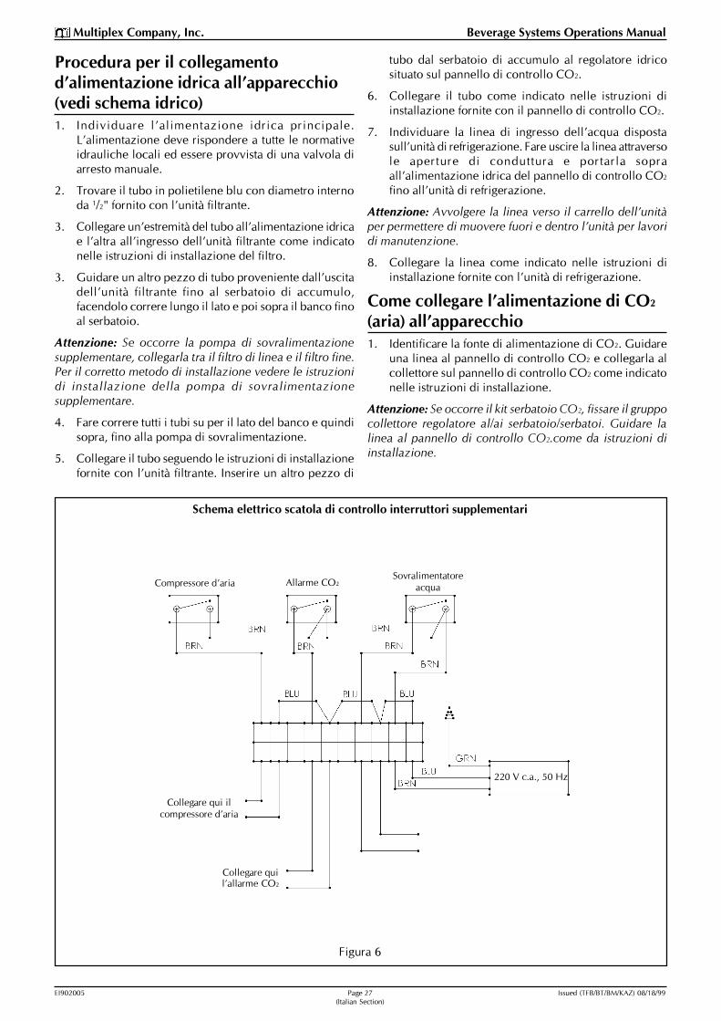
Figura 6
Schema elettrico scatola di controllo interruttori supplementari
Procedura per il collegamentod�alimentazione idrica all�apparecchio(vedi schema idrico)1. Individuare l�alimentazione idrica principale.
L�alimentazione deve rispondere a tutte le normativeidrauliche locali ed essere provvista di una valvola diarresto manuale.
2. Trovare il tubo in polietilene blu con diametro internoda 1/2" fornito con l�unità filtrante.
3. Collegare un�estremità del tubo all�alimentazione idricae l�altra all�ingresso dell�unità filtrante come indicatonelle istruzioni di installazione del filtro.
3. Guidare un altro pezzo di tubo proveniente dall�uscitadell�unità filtrante fino al serbatoio di accumulo,facendolo correre lungo il lato e poi sopra il banco finoal serbatoio.
Attenzione: Se occorre la pompa di sovralimentazionesupplementare, collegarla tra il filtro di linea e il filtro fine.Per il corretto metodo di installazione vedere le istruzionidi installazione della pompa di sovralimentazionesupplementare.
4. Fare correre tutti i tubi su per il lato del banco e quindisopra, fino alla pompa di sovralimentazione.
5. Collegare il tubo seguendo le istruzioni di installazionefornite con l�unità filtrante. Inserire un altro pezzo di
tubo dal serbatoio di accumulo al regolatore idricosituato sul pannello di controllo CO2.
6. Collegare il tubo come indicato nelle istruzioni diinstallazione fornite con il pannello di controllo CO2.
7. Individuare la linea di ingresso dell�acqua dispostasull�unità di refrigerazione. Fare uscire la linea attraversole aperture di conduttura e portarla sopraall�alimentazione idrica del pannello di controllo CO2
fino all�unità di refrigerazione.
Attenzione: Avvolgere la linea verso il carrello dell�unitàper permettere di muovere fuori e dentro l�unità per lavoridi manutenzione.
8. Collegare la linea come indicato nelle istruzioni diinstallazione fornite con l�unità di refrigerazione.
Come collegare l�alimentazione di CO2
(aria) all�apparecchio1. Identificare la fonte di alimentazione di CO2. Guidare
una linea al pannello di controllo CO2 e collegarla alcollettore sul pannello di controllo CO2 come indicatonelle istruzioni di installazione.
Attenzione: Se occorre il kit serbatoio CO2, fissare il gruppocollettore regolatore al/ai serbatoio/serbatoi. Guidare lalinea al pannello di controllo CO2.come da istruzioni diinstallazione.
Collegare quil�allarme CO2
Collegare qui ilcompressore d�aria
Compressore d�aria Allarme CO2Sovralimentatore
acqua
220 V c.a., 50 Hz

EI902005 Page 28 Issued (TFB/BT/BM/KAZ) 08/18/99(Italian Section)
Multiplex Company, Inc. Beverage Systems Operations Manual
Collegamento delle condutture di alimentazionedell�unità di refrigerazione
Figura 7
2. Se occorre il kit compressore d�aria supplementare,guidare la linea in uscita dal compressore d�ariaattraverso il pannello di controllo CO2 come indicatonelle istruzioni di installazione.
3. Svolgere la linea situata sull�ultima pompa sul pannellopompa Bag-in-Box.
4. Fare correre la linea sul lato e quindi fino al regolatoredi CO2 sul pannello di controllo CO2.
5. Collegare la linea al regolatore pannello di controlloCO2 come indicato nelle istruzioni di installazionefornite con il pannello di controllo CO2.
6. Trovare la linea di alimentazione CO2 all�internodell�unità di refrigerazione.
7. Fare uscire la linea dalle aperture di conduttura fino alpannello di controllo CO2 (vedi figura 6). Accertarsi diavvolgere la linea sotto verso il carrello dell�unità perpermettere di muovere fuori e dentro l�unità per lavoridi manutenzione.
8. Collegare la linea al pannello di controllo CO2 secondole istruzioni di installazione del pannello di controlloCO2.
Collegamento delle condutture dialimentazione dell�unità direfrigerazione (vedi figura 7)Definizione della conduttura di alimentazione dellosciroppo e suo collegamento alle pompe1. Dopo aver estratto il carrello, togliere il coperchio e
individuare le linee di alimentazione sciroppo.
2. Portare i tubi all�esterno tramite le aperture diconduttura laterali e legare insieme queste linee.
3. Avvolgere il fascio di linee verso il carrello e quindi dinuovo verso il pannello pompe. Questo assicura checi sia una lunghezza sufficiente per permettere alcarrello di uscire e rientrare.
4. Collegare le linee di alimentazione prodotto allapompa. Accertarsi che i numeri sulle linee coincidanocoi numeri sulla pompa.
5. Bloccare le linee in posizione per mezzo dei morsettiforniti con il kit di installazione del refrigeratore.
Collegamento delle condutture di ricircolo1. Trovare la conduttura di ricircolo con una ricerca della
conduttura. Per una conduttura alta, fare passare laconduttura attraverso il foro quadrato posto sopra ilbanco superiore, e quindi verso il basso lungo il retrodel banco.
2. Avvolgete la conduttura verso il carrello e quindi dinuovo attraverso le aperture di conduttura laterali, perassicurare una lunghezza sufficiente per permettere alcarrello di uscire e rientrare.
3. Collegare la conduttura alle serpentine diraffreddamento come indicato nelle istruzioni diinstallazione fornite con l�unità di refrigerazione.
Caricamento del rifornimento dello sciroppo alle Bag-in-BoxLa configurazione numerica delle Bag-in-Box prevede chei numeri dispari vadano sul ripiano superiore e i numeripari su quello inferiore. Ogni gusto di sciroppo richiededue (2) Bag-in-Box sul ripiano, una accanto all�altra. Caricarei ripiani con i prodotti necessari e installare i collegamenticon le Bag-in-Box.
Avviamento del sistemaOra il sistema dovrebbe essere pronto per essere avviato.Le istruzioni di installazione dell�unità di refrigerazioneindicheranno le procedure necessarie per avviare il sistema.Dopo aver eseguito queste istruzioni, l�installazione delSistema distributore di bevande Multiplex MV2000 ècompletata.
Condotta di ricircolo
Avvolgere la conduttura di ricircolo e lelinee dello sciroppo (verso il fondo del
carrello come indicato, per permettere alcarrello di uscire e rientrare)

EI902005 Page 29 Issued (TFB/BT/BM/KAZ) 08/18/99(Italian Section)
Multiplex Company, Inc. Beverage Systems Operations Manual
Schema idrico Modello MV2000


Einbau-Anweisungen fürMultiplex Getränke-Anlagen
Getränke System ModellMV2000 Edelstahl
German Section

EI902005 Page 32 Issued (TFB/BT/BM/KAZ) 08/18/99 (German Section)
Multiplex Company, Inc. Beverage Systems Operations Manual
Warnhinweise: zur Vermeidung schwerwiegender Verletzungen
Wichtig: Lesen Sie die folgenden Warnhinweise, bevor Sie mit dem Einbaubeginnen. Bei Nichtbeachtung besteht Lebensgefahr oder die Gefahr schwererVerletzungen.
JA Beachten Sie alle nationalen und lokalen gesetzlichen Einbau- undSicherheitsvorschriften.
JA Alle ankommenden elektrischen Bedienungsschalter während der Wartung,Installation oder Reparatur eines Gerätes �aus�schalten.
JA Kontrollieren Sie, ob alle Anschlüsse am/an den Karbonator/ n dicht sind. DiesePrüfung sollte mit einem Mutternschlüssel durchgeführt werden, um einwandfreieDichtigkeit zu gewährleisten.
JA Vor Inbetriebnahme eines Gerätes den Druck an den Druckminderern überprüfen.
JA Augenschutz verwenden, wenn Sie in der Nähe von Kühlmitteln arbeiten.
JA Generell Vorsicht bei allen Geräten bei Arbeiten an Metallkanten.
JA Vorsicht im Umgang mit CO2-Flaschen und �Manometern. Sichern Sie die Flaschensorgfältig gegen Beschädigung.
JA CO2� Flasche/n in gut belüfteten Räumen lagern.
NEIN CO2� Flaschen werfen oder fallenlassen. Stellen Sie sicher, daß der/die Flasche/nmittels Kette senkrecht gelagert wird/werden.
NEIN Den/die CO2� Flasche/n direkt an einen Produktbehälter anschließen. Dies würde zueiner Explosion führen mit möglicher Verletzung oder Todesfolge. Am besten ist es,die/den CO2� Flasche/n an einen/die Druckregler anzuschließen.
NEIN Die CO2� Flaschen bei einer Temperatur von über 125°F (51.7°C) in der Nähe vonÖfen, Heinzstrahlern oder Heizkörpern lagern.
NEIN CO2-Gas aus dem alten Flaschen entweichen lassen.
NEIN Innere Geräte-Kühlleitungen berühren, einige Kühlleitungen können Temperaturenvon 200°F (93.3°C) und darüber erreichen.

EI902005 Page 33 Issued (TFB/BT/BM/KAZ) 08/18/99 (German Section)
Multiplex Company, Inc. Beverage Systems Operations Manual
Trägergestellanordnung
Abbildung 1
Auspacken des Träger-Gestells
Unteres Trägergestell
Kühlgerät Ausziehtablett
Oberes Fach zurLagerung der�Bag-In-Box�
UnteresRegalfach
1/4"-20 x 7/8"Sechsk.kopfmutter
1/4"-20 Edelstahl-Kreuzlochschrauben
TropfpfanneOberes Fach
Anmerkung: Obergestell mitden vier (4) Sechskantkopf-muttern u. Kreuzlochschraubenam Untergestell befestigen.
Untergestell
Kühlgerät Ausziehtablett
Einzelheit A: Tablettsperre
1 1/2" Lang- Bolzen
flacheSechskantmutter
Sicherungsscheibe
Fuß Untergestell
Ausziehtablett
EinführungDas Multiplex Getränkesystem MV2000 ist eine kompak-te Mehrfach-Anlage. Diese Rahmengestellvorrichtung er-möglicht das Stapeln von acht (8) �Bag-In-Box�-Einheiteneinschließlich Getränkepumpen und Umschaltventilen. Alsweitere Standardausrüstung enthält dieses Gestell darüberhinaus einen Wasservorratstank und eine CO2 Kontrollttafel.Der Wasservorratstank garantiert einen konstanten Wasser-druck der Anlage. Die CO2 -Kontrolltafel garantiert einegeregelte Kohlendioxid-Beschickung der Getränkepumpenund dem Karbonator.
Das Getränkesystem MV2000 schließt als Zubehör einenLuftkompressor, eine Wasserdruckerhöhungspumpe, einWasserfilterpaket und einen CO2 -Flaschenhalter ein. Die-ses Gestell ist so konstruiert, daß die meisten Teile direktam Gestell angebracht sind. Das Zubehör kann an der Wandinstalliert werden, wenn das Restaurantlayout dies erfor-dert oder zulässt.
Auspacken des Trägergestells und seiner Teile1. Verpackungsmaterial sorgfältig vom Gestell entfernen.
Prüfen Sie, ob der Karton wirklich leer ist, bevor Sieihn entsorgen.
2. Nehmen Sie alle verpackten Teile aus dem Gestell her-aus (Tropfpfanne, Vorratsbehälter-Set, CO2-Kontrolltafel,Wasserdruckerhöhungspumpe sowie sämtlichesInstallations- Material.
3. Oberes �Bag-In-Box�-Rack innen im unteren Gestellentfernen (siehe Abbildung 1). Das untere Regal ent-fernen.
Aufstellen des Trägerständers1. Oberes Rack oben auf den unteren Träger setzen. Schlit-
ze des Trägers und Racks ausrichten.
2. Die im Hardware-Beutel mitgelieferten vier (4) 1/4"-20x 3/4" Sechskantkopfschrauben und Sicherungsmutternzurechtlegen. Mit den Bolzen und Muttern das obereGestell (Rack) mit dem unteren Träger verschrauben.
Anmerkung: Erst festziehen, wenn Gestell und Träger ineine Linie gebracht sind.
3. Das obere Gestell mit der Rückseite des Gestells unddes Trägers bündig ausrichten. Bolzen festziehen.
4. Tropfschale innerhalb der Seitenkanäle des unterenTrägers positionieren.
5. Den ausziehbaren Wagen aus dem Trägergestell zie-hen. Hierzu die Stange an jeder Seite vorn am Wagenziehen, bis ein Einschraubloch auf jeder Seite direkthinter den Vorderbeinen erscheint (siehe Abbildung 1).
6. Die beiden (2) 1/4"-20 x 1 1/2" Lang-Bolzen und die1/4"-20 Muttern zur Hand nehmen, und dieGegenmuttern aufschieben. Eine (1) Mutter auf jedenBolzen aufschrauben, dann jeweils einen Bolzen in dieEinschraublöcher schrauben (siehe Abbildung 1, Ein-zelheit A).
7. Das montierte Gestell an die gewünschte Stelle brin-gen. Gestell mittels Ausrichtbolzen an den Füßen anallen vier (4) Beinen ausrichten. Das untere Gestellwieder an seinen ursprünglichen Platz bringen.
8. Nun ist das Gestell fertig zum Einbau des Multiplex-Kühlgerätes und dem Standardzubehör.
Einbau des Standard-ZubehörsTankbehälterset (siehe Abbildung 2)1. Das zusammen mit dem Gestell verpackte Set zur Hand
nehmen. Alle Teile aus dem Karton entfernen.Montageanordndung zur Hand nehmen und Armaturauf den Tank schrauben.
Anmerkung: Dichtmittel beim Einschrauben verwenden,um Undichtigkeiten zu vermeiden.
2. Die vier (4) oben am oberen Rack vorgesehenenMontagelöcher bestimmen.
3. Die vier (4) Bügel unter Verwendung der vier (4) mitdem Set mitgelieferten Schrauben und Muttern #10-32montieren.

EI902005 Page 34 Issued (TFB/BT/BM/KAZ) 08/18/99 (German Section)
Multiplex Company, Inc. Beverage Systems Operations Manual
Oberes RackDeckplatte
Gewindegarniturteile an Behälter schrauben.Fittings in Richtung Wasserfiltersitz führen.
#10-32 Befestigungsschrauben und Muttern(erforderl.:vier [4])
Behälter-Haltestreifen (ent-sprechenddes/der Behälterdurchmesser)
4. Den Vorratsbehälter so positionieren, daß die Anschluß-stücke zur Rückseite des Gestells und zu der Seite, anwelcher der Filter eingebaut werden soll, ausgerichtetsind. Bügel so formen, daß sie dem Radius des Behäl-ters entsprechen.
5. Die beiden (2) Bügelsets unter Verwendung der bei-den (2) 1/4"-20 Schrauben und Muttern zusammen-schrauben (siehe Abbildung 2).
CO2 �Kontrolltafel (siehe Abbildung 3)Die CO2 �Kontrolltafel kann auf jeder Seite des Gestellsoder auch an der Wand in der Nähe des Gestells (ohneAbbildung) montiert werden.
1. Machen Sie die ebenfalls zusammen mit dem Gestellverpackte CO2 �Kontrolltafel ausfindig und entfernenSie alle Teile aus dem Karton.
2. Sitz des Filterpakets und der CO2 �Kontrolltafel amGestell bestimmen.
3. Die beiden (2) Montagelöcher auf der Oberseite desoberen Racks ermitteln.
4. Die CO2 �Kontrolltafel unter Verwendung der beiden(2) Öffnungen mit den beiden (2) 1/4"-20 x 3/4" Lang-Schrauben und zusammen mit dem Einbauset des Ge-stells gelieferten 1/4"-20 Muttern montieren.
5. Unteren Arretierwinkel und die beiden (2) #10-32 x 1/2" Lang-Schrauben feststellen.
6. Winkel an der Rückseite der Platte mit den Schraubender Vorderseite befestigen.
Anmerkung: Manometer drehen, daß sie von vorn sichtbarsind. Manometer im Uhrzeigersinn drehen, um die Gewin-de festzuziehen, um Undichtigkeiten zu vermeiden..
Wasserfilterpaket (siehe Abbildung 3)1. Filterpaket aus dem Karton nehmen und das
Installations-Material zur Hand nehmen.
Anmerkung: Filterpaket entweder rechts oder links amGestell montieren. Vorzugsweise jedoch an der linken Sei-te.
2. Die Montageöffnungen an den Füßen des unteren Ge-stells feststellen machen. Die 1/4"-20 x 7/8" Lang-schrauben an der Innenseite des Fußes einsetzen. Die1/4"-20 Überwurfmuttern außen befestigen.
Anmerkung: Diese Schrauben nicht vollständig anziehen(siehe Abbildung 3).
3. Filterplatte an den Schrauben durch die Lochöffnungenan der Platte in die richtige Stellung bringen. DieMuttern fest anziehen.
CO2 �Flaschenhalter1. Set auspacken. Machen Sie die mit dem Set gelieferten
Flaschenhalter und Installationsmaterial ausfindig. (Diemit dem Set als Option mitgelieferten Montagebügelfinden keine Verwendung beim Gestell MV2000.)
2. Bestimmen Sie die Seite für die CO2-Behälter. MachenSie die Öffnungen am oberen Rack für die Montageausfindig.
Anmerkung: Der Falschenhalter wird das Filterpaket frei-geben, deshalb kann/können der/die Behälter auf der glei-chen Seite wie das Filterpaket sein
3. Halter an den Beinen des Gestells mittels der1/2"-20 x 1/2" Sechskantkopfschrauben und 1/4"-20 Über-wurfmuttern befestigen.
Anmerkung: Schrauben an der Innenseite der Beine ein-setzen und Überwurfmutter außen am Ständerbein verwen-den. So ausführen, daß das ausziehbare Fach entfernt wer-den kann.
4. Alle Muttern fest anziehen.
Wasservorratsbehälter-Set
Abbildung 2

EI902005 Page 35 Issued (TFB/BT/BM/KAZ) 08/18/99 (German Section)
Multiplex Company, Inc. Beverage Systems Operations Manual
AngleCO2 Control PanelMounting Bracket
CO2 �Schalttafel
Befestigungsschraubenund Muttern
(Lieferung zusammenmit Trägergestell
Wasserfilteraggregat
Befestigungsschrauben undMuttern (Lieferung
zusammen mit Trägergestell
Verfahren zum Einbau des Kühlgerätsam Trägergestell (siehe Abbildung 4)1. Gerätewagen ausrollen und Vorderräder während des
Aufstellens des Kühlgeräts auf dem Wagen blockieren.
2. Gerät nach vorn hin und immer nach rechts auf denWagen stellen. (siehe Abbildung 4).
3. Die beiden (2) Öffnungen unter dem Wagen mit denÖffnungen des Geräts für die Schrauben ausrichten.Gerät unter Verwendung des für das Kühlgeräte-Ein-bauset mitgelieferten Bolzens verschrauben.
4. Weitere Einbauschritte gemäß Anweisung in der für dasGerät beigefügten Einbauanweisungen.
Anmerkung: Weitere Anweisungen zur Führung der Ver-sorgungsleitungen werden an späterer Stelle in dieser Pu-blikation behandelt. Beachten Sie beim Anschluß des Ge-räts an die eingehende Stromquelle, daß sich das Gerät umzirka 30 Zoll nach vorne bewegen können muß . Wird dieFernkondensator-Anlage verwendet, müssen mindestenszwei (2) von 24" Durchmesser Leitungen der Rückseitedes Kühlgeräts verwendet werden, damit auch dieses Teilausgerollt werden kann.
Einbau des wahlweisen ZubehörsAnmerkung: Sämtliches Zubehör wird möglicherweise nichtfür alle Einbauten benötigt.
Aufbau der Wasser-Druckaufbaupumpe(siehe Abbildung 5)Die Multiplex Wasserdruckaufbaupumpe, Typ WBK10,wird an der oberen rechten Seite des oberen Racks ange-bracht.
1. Nehmen Sie die Wasser-Druckerhöhungspumpe ausdem Karton.
2. Nehmen Sie den mit der Pumpe gelieferten Montage-bügel zur Hand. Befestigen Sie den Bügel an der Rück-seite oben mit aufgestellter Lippe gegen die Rückseitedes Gestells. Befestigen Sie ihn mittels der beiden (2)mit dem als Installationsset für das Gestell mitgeliefer-ten 1/4"-20 x 3/4" Langschrauben und 1/4"-20 Muttern(siehe Abbildung 5, Einzelheit A).
3. Setzen Sie die Wasserpumpe auf das obere Teil überder Konsole. Schieben Sie das Aggregat nach vorn, sodaß die Rückseite der Platte unter den Befestigungs-bügel gleiten kann.
4. Befestigen Sie die Vorderseite der Platte mit den bei-den (2) zusammen mit dem Einbauset für das Gestellgelieferten 1/4"-20 x 3/4" Langschrauben und 1/4"-20Muttern.
Abbildung 3A
Befestigungsschraubenund Muttern
(Lieferung zusammenmit Trägergestell
CO2 Tank HoldDown Bracket
Abbildung 3
CO2 �Schalttafelbefestigung mit Rack-Wasserfilterpaket

EI902005 Page 36 Issued (TFB/BT/BM/KAZ) 08/18/99 (German Section)
Multiplex Company, Inc. Beverage Systems Operations Manual
Abbildung 5
Wasserzusatzpumpenaggregat
Einzelheit A
diese Einbauöffnungenverwenden
Luftkompressor (siehe Abbildung 5)Der Luftkompressor wird am Oberteil des oberen Gestellsauf der linken Seite befestigt.
1. Luftkompressor aus dem Karton nehmen und Aggregataus der Verpackung nehmen.
2. Die vier (4) Montageöffnungen im Oberteil ausfindigmachen und den Luftkompressor in Position bringen.Luftkompressor unter Verwendung der zusammen mitdem Luftkompressor gelieferten Installations Materialbefestigen.
3. Die elektrischen Anschlüsse nach den dem Luftkom-pressor beigefügten Anweisungen vornehmen.
Zubehör-Schaltkasten (siehe Abbildung 5)1. Schaltkasten und die beiden (2) Befestigungsschrauben
ausfindig machen.
2. Schaltkasten so installieren, daß die Schalter mit denbeiden (2) Befestigungsschrauben der Unterseite desOberteils zur Vorderseite zeigen.
3. Siehe Abbildung 6 �Zubehör Schaltplan des Schaltka-sten bezüglich der Drahtverbindungen der Einzeltei-le.
Verfahren zum Anschluß desWasserzulaufs zum Gerätesystem(siehe Wasserzulaufdiagramm)1. Machen Sie den Hauptwasserzulauf ausfindig. Der
Zulauf muß allen lokalen Installationsvorschriften ent-sprechen und mit einem manuellen Abschaltventil aus-gerüstet sein.
2. Nehmen Sie den zusammen mit der Filtergruppe ge-lieferten blauen Polyschlauch von 1/2" Innendurch-messer zur Hand.
2. Schließen Sie ein (1) Ende des Schlauchs an den Wasser-zulauf und das andere Ende an den Filtersystemeinlaßgemäß Filtereinbauanweisungen.
3. Führen Sie ein anderes Schlauchstück vom Filtersystem-auslaß heraus zum Sammelbehälter seitlich am Gestellentlang nach oben und führen Sie es über das Oberteildes Behälters.
Anmerkung: Wird die Option der Druckerhöhungspumpegewünscht, so schließen sie sie zwischen Vorfilter und Fein-filter an. Siehe Einbauanweisungen für die Druckerhöhungs-pumpe bezüglich des korrekten Anschlußverfahrens.
4. Führen Sie alle Schläuche am Gestell entlang seitlichnach oben und über das Oberteil der Druckerhöhungs-pumpe .
Blockierräder (verhindert Rollendes Tabletts während d. Aufbaus
der Baugruppe auf d. Tablett)
Befestigungsschrauben(Lieferung zus. mit
Aggregat)
Kühlaggregat
Einbau des Kühlaggregats am Trägerständer
Abbildung 4
Option Luft- KompressorBefestigungsschraubenund �muttern Wasser-
Aufladegebläse(Lieferung mit dem
Wasser-Aufladegebläse)
BefestigungswinkelWasser-Aufladegebläse
(Lieferung mit demWasser-
Aufladegebläse) (sieheEinzelheit A)
Deckplatte des oberen�Bag-In-Box�-Racks
Wasser-Aufladegebläsegruppe
Typ WBK10
BefestigungsschraubenSchaltkasten (Lieferung zus.
mit Schaltkasten)
Zubehör Schaltkasten

EI902005 Page 37 Issued (TFB/BT/BM/KAZ) 08/18/99 (German Section)
Multiplex Company, Inc. Beverage Systems Operations Manual
5. Schließen Sie den Schlauch gemäß den zusammen mitdem Filtersystem gelieferten Einbauanweisungen an.Legen Sie ein anderes Schlauchstück vom Behältertankzum Wasserdruckregler an der CO2-Schalttafel.
6. Verbinden Sie den Schlauch gemäß den zusammen mitdem Filtersystem gelieferten Einbauanweisungen.
7. Machen Sie die am Kühlgerät vorhandene Einlaß-wasserleitung ausfindig. Führen Sie die Leitung Zu-leitungsöffnung heraus und nach oben zur CO2-Schalt-tafel des Wasserzulaufs zum Kühlgerät.
Anmerkung: Schleifen Sie die Leitung in Richtung Geräte-wagen, so daß das Gerät zum Service hin und herbewegtwerden kann.
8. Schließen Sie die Leitung gemäß den dem Kühlgerätbeigefügten Einbauanweisungen an.
Anschluß der CO2 (Luft)-Zuleitung andie Gerätegruppe1. Machen Sie die CO2-Versorgungsstelle ausfindig. Füh-
ren Sie eine Leitung zur CO2 -Kontroltafel und schlie-ßen Sie sie an gemäß Einbauanweisung an dieSammelleitung (das Ansaugrohr) an der CO2 -Kontrolltafel an.
Anmerkung: Wird die CO2 �Kontrolltafel-Set gewünscht,
so befestigen Sie den CO2 Hochdruckschlauch an dem/denBehälter/n. Führen Sie die Leitung gemäß Einbauan-weisungen zur CO2 �Kontrolltafel.
2. Sofern die Option des Luftkompressorsets gewünschtwird, führen Sie die Auslaßleitung vom Luftkompres-sor durch die CO2 �Kontrolltafel und schließen Sie siegemäß Einbauanweisung an.
3. Entspulen Sie die sich an der letzten Pumpe an der �Bag-in-Box�-Pumpentafel befindliche Leitung.
4. Führen Sie die Leitung seitlich heraus zur CO2 -Druck-verteilung an der CO2 �KontrolltafelSchalttafel.
5. Verbinden Sie die Leitung gemäß der zusammen mitder CO2 �Kontrolltafeltafel gelieferten Einbauanweisungmit dem Regler der CO2 �Kontrolltafeltafel.
6. Machen Sie die CO2 �Versorgungsleitung im Kühlgerätausfindig
7. Führen Sie die Leitung aus der Zuleitungsöffnung her-aus zur CO2 �Kontrolltafel (siehe Abbildung 6). Verge-wissern Sie sich, daß die Leitung eine Schleife nachunten in Richtung Wagen bildet, so daß das Teil zumService ein- und ausgefahren werden kann.
8. Schließen Sie die Leitung gemäß den für die CO2 �Kontrolltafel mitgelieferten Einbauanweisungen an dieCO2�Kontrolltafel an.
CO2 -Alarm hieranschließen
Luftkompressor hieranschließen
Luftkompressor CO2 -Alarm Wassergebläse(pumpe)
220 VAC, 50 Hz
Abbildung 6
Schaltplan Zubehör Schaltkasten

EI902005 Page 38 Issued (TFB/BT/BM/KAZ) 08/18/99 (German Section)
Multiplex Company, Inc. Beverage Systems Operations Manual
Anschluß der Versorgungsleitungen des Kühlgeräts
Abbildung 7
Anschluß der Versorgungsleitungen derKühlvorrichtung (siehe Abbildung 7)Verlegen der Sirup-Versorgungsleitung und deren Anschlußan die Pumpen
1. Bei ausgefahrenem Auszieh-Wagen obere Abdeckungentfernen und die Sirup-Versorgungsleitungen bestim-men.
2. Leitungen aus den seitlichen Leitungsöffnungen heraus-führen und bündeln.
3. Bündel in einer Schleife zum Wagen und dann zurückzur Pumpentafel führen. Somit ist genügend Länge vor-handen, damit der wagen ein- und ausgefahren wer-den kann.
4. Schließen Sie die Versorgungsleitungen für das Produktan die Pumpe an. Vergewissern Sie sich, daß die Zif-fern auf den Leitungen den Ziffern auf der Pumpe ent-sprechen.
5. Klemmen Sie die Leitungen unter Verwendung der mitdem Installations-Material gelieferten Klemmen fest.
Anschluß der Umlaufleitung1. Bestimmen Sie die Umlaufleitung am Leitungsrahmen.
Bei Freileitungsrohrleitungen führen Sie die Leitungdurch die viereckige Öffnung im Oberteil des oberenRacks und dann an der Rückseite des Gestells nachunten.
2. Schleifen Sie die Leitung zum Wagen hin und zurücknach oben durch die seitliche Leitungsöffnung, um eineausreichende Länge zum Ein- und Ausfahren des Wa-gens sicherzustellen.
3. Verbinden Sie die Leitung zu den Kühlschlangen an-hand der zusammen mit dem Kühlaggregat geliefertenEinbauanweisungen.
Beschickung der �Bag-In-Box�-SirupversorgungsleitungDie Ziffernanordnung für die �Bag-In-Box� sieht vor, daßdie ungeraden Zahlen zum oberen Fach gehen und diegeraden Zahlen sich am Unterteil befinden. Jeder Sirup-geschmack erfordert zwei (2) �Bag-In-Box�-Einheiten neben-einander im Regal. Stellen Sie die erforderlichen Produktein die Regale und montieren Sie die Verbindunsleitungenzur �Bag-In-Box�.
Einschalten des GerätsDas Gerät sollte jetzt startbereit sein. Die Einbauan-weisungen der Kühlvorrichtung erläutern die notwendigenSchritte zur Inbetriebnahme des Geräts. Nach Durchfüh-rung dieser Einbauanweisungen zur Inbetriebnahme ist dasMultiplex Getränkesystem MV2000 vollständig.
Umlaufleitung
Umlaufleitung und Sirupleitungen schleifen (zumBoden des Tabletts hin, wie dargestellt, damit das
Tablett ein- und ausgefahrent werden kann)

EI902005 Page 39 Issued (TFB/BT/BM/KAZ) 08/18/99 (German Section)
Multiplex Company, Inc. Beverage Systems Operations Manual
Wasserkreislauf-Diagramm Typ MV2000

Multiplex Company, Inc.250 Old Ballwin Road w St. Louis, Missouri 63021-4800 Tel: 636.256.7777 w Fax: 636.527.4313 e-mail: [email protected] w www.multiplex-beverage.com
In accordance with our policy of continuous product development andimprovement, this information is subject to change at any time without notice.
Printed in The United States of America EI902005Issued August 1999