Multiple Stiffened Cold-Formed Steel Profiles for Cylindrical Vault Roofing Systems
24
Journal of Constructional Steel Research 57 (2001) 831–854 www.elsevier.com/locate/jcsr Multiple stiffened cold-formed steel profiles for cylindrical vault roofing systems Stefano Caramelli, Pietro Croce, Walter Salvatore * Department of Structural Engineering, University of Pisa, Via Diotisalvi 2, 56126 Pisa, Italy Received 28 November 2000; received in revised form 11 May 2001; accepted 18 May 2001 Abstract Cold-formed steel structures have been experiencing a considerable increase in both the civil and industrial building sectors. The introduction of new types of high strength and/or multiple stiffened profiles, as a consequence of improved production techniques, has encour- aged the development of innovative applications and structural systems. The consequent need for simple, yet reliable calculation methods of such structures, in turn, has engendered new studies directed at characterizing their failure mechanisms, post-critical behaviour and instability phenomena. This paper provides an illustration and in-depth discussion of the results of a wide-ranging numerical–experimental analysis conducted on multiple stiffened, cold-formed profiles within the framework of the development of an innovative structural application for fabricating indus- trial cylindrical vault roofing. 2001 Elsevier Science Ltd. All rights reserved. Keywords: Cold-formed steel structure; Multiple intermediate stiffeners; Experimental tests; Non-linear analysis 1. Introduction In recent years, cold-formed steel structures, with the development of innovative structural applications in both civil and industrial construction [1], have been experi- encing a considerable increase due mainly to improvements in the mechanical charac- teristics of the steel and advances in the production technologies. In the design of roof flooring and joists, in particular, the elevated mechanical * Corresponding author. E-mail address: [email protected] (W. Salvatore). 0143-974X/01/$ - see front matter 2001 Elsevier Science Ltd. All rights reserved. PII:S0143-974X(01)00018-9
-
Upload
tiago-lopes -
Category
Documents
-
view
19 -
download
0
Transcript of Multiple Stiffened Cold-Formed Steel Profiles for Cylindrical Vault Roofing Systems

Journal of Constructional Steel Research 57 (2001) 831–854www.elsevier.com/locate/jcsr
Multiple stiffened cold-formed steel profiles forcylindrical vault roofing systems
Stefano Caramelli, Pietro Croce, Walter Salvatore*
Department of Structural Engineering, University of Pisa, Via Diotisalvi 2, 56126 Pisa, Italy
Received 28 November 2000; received in revised form 11 May 2001; accepted 18 May 2001
Abstract
Cold-formed steel structures have been experiencing a considerable increase in both thecivil and industrial building sectors. The introduction of new types of high strength and/ormultiple stiffened profiles, as a consequence of improved production techniques, has encour-aged the development of innovative applications and structural systems.
The consequent need for simple, yet reliable calculation methods of such structures, in turn,has engendered new studies directed at characterizing their failure mechanisms, post-criticalbehaviour and instability phenomena.
This paper provides an illustration and in-depth discussion of the results of a wide-rangingnumerical–experimental analysis conducted on multiple stiffened, cold-formed profiles withinthe framework of the development of an innovative structural application for fabricating indus-trial cylindrical vault roofing. 2001 Elsevier Science Ltd. All rights reserved.
Keywords: Cold-formed steel structure; Multiple intermediate stiffeners; Experimental tests; Non-linearanalysis
1. Introduction
In recent years, cold-formed steel structures, with the development of innovativestructural applications in both civil and industrial construction [1], have been experi-encing a considerable increase due mainly to improvements in the mechanical charac-teristics of the steel and advances in the production technologies.
In the design of roof flooring and joists, in particular, the elevated mechanical
* Corresponding author.E-mail address: [email protected] (W. Salvatore).
0143-974X/01/$ - see front matter 2001 Elsevier Science Ltd. All rights reserved.PII: S0143 -974X(01)00018-9
832 S. Caramelli et al. / Journal of Constructional Steel Research 57 (2001) 831–854
Fig. 1. Vault arch roofing using cold-formed steel profiles, transverse view.
performances of such profiles and the consequent ability to achieve greater spansfavour the adoption of new constructive systems.
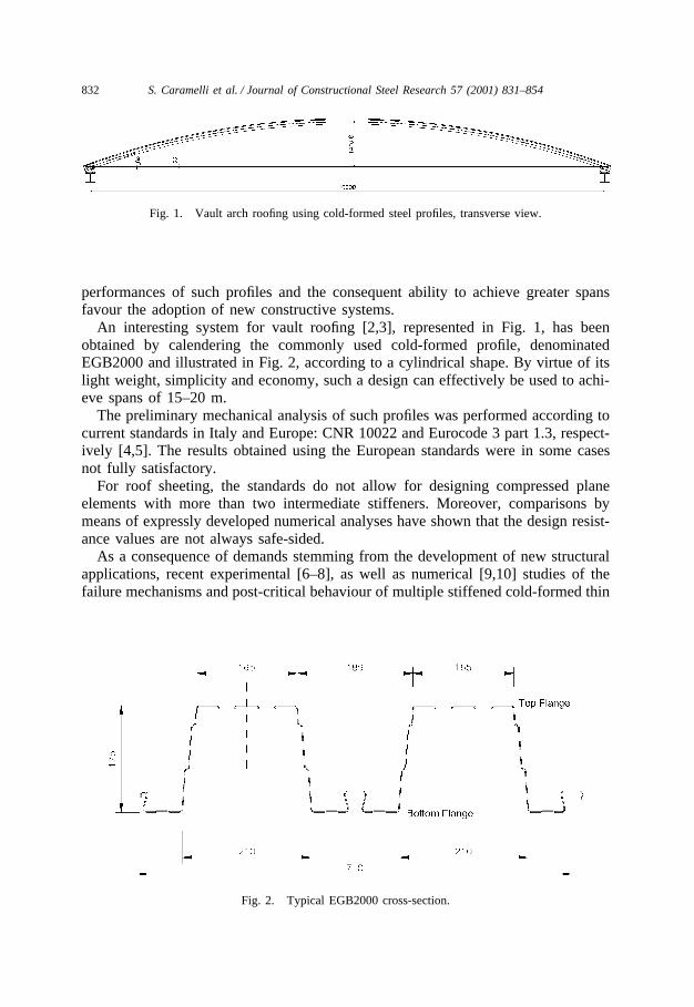
An interesting system for vault roofing [2,3], represented in Fig. 1, has beenobtained by calendering the commonly used cold-formed profile, denominatedEGB2000 and illustrated in Fig. 2, according to a cylindrical shape. By virtue of itslight weight, simplicity and economy, such a design can effectively be used to achi-eve spans of 15–20 m.
The preliminary mechanical analysis of such profiles was performed according tocurrent standards in Italy and Europe: CNR 10022 and Eurocode 3 part 1.3, respect-ively [4,5]. The results obtained using the European standards were in some casesnot fully satisfactory.
For roof sheeting, the standards do not allow for designing compressed planeelements with more than two intermediate stiffeners. Moreover, comparisons bymeans of expressly developed numerical analyses have shown that the design resist-ance values are not always safe-sided.
As a consequence of demands stemming from the development of new structuralapplications, recent experimental [6–8], as well as numerical [9,10] studies of thefailure mechanisms and post-critical behaviour of multiple stiffened cold-formed thin
Fig. 2. Typical EGB2000 cross-section.

833S. Caramelli et al. / Journal of Constructional Steel Research 57 (2001) 831–854
profiles revealed the limits of current design regulations and the inadequacy of theverification methods set forth by governing standards [11,12].
A more detailed study of the mechanical behaviour of such profiles was thereforecalled for in order to determine, by recognizing the fundamental parameters govern-ing their structural response, new, suitable models on which to base the developmentof a general design methodology for the entire structural system.
Application of the EGB2000 profile to cylindrical vault roofing according to thescheme in Fig. 1 requires knowing the profile’s strength and structural response toabsolutely general load stresses, whether they be simple compression, pure bendingor combined bending and compression. Thus, it was necessary to carry out wideranging numerical and experimental investigations to deduce all the necessary infor-mation regarding the profile’s mechanical behaviour.
The experimental tests were aimed at determining the resistance domain of theprofile’s section and identifying its collapse mechanisms (linked mainly to phenom-ena of overall and local stability). The influence of the various parameters in playwas subsequently analysed by numerical non-linear analyses.
By comparing the results of such investigations with those obtainable by appli-cation of current design standards, it was possible to garner useful indications, notonly regarding the structural applications in question, but also for possible develop-ment of a new generalized calculation model.
Fig. 3. Effective area, St 355 steel grade, t=0.8 mm, pure compression. t is the profile thickness, tred isthe reduced thickness, c=tred/t.

834 S. Caramelli et al. / Journal of Constructional Steel Research 57 (2001) 831–854
Fig. 4. Effective area, St 355 steel grade, t=0.8 mm, pure bending. t is the profile thickness, tred is thereduced thickness, c=tred/t.
Table 1EGB2000 resistance values evaluated by using Eurocode 3 part 1.3
Steel grade Thickness (mm) Nt.rd (daN/m) Nc.rd (daN/m) Mc.rd (daN cm/m)
St235 0.8 35,596 24,159 111,5731.0 46,009 33,079 150,5411.2 55,666 42,033 190,0181.5 70,150 55,764 253,770
St275 0.8 41,655 26,748 122,1801.0 53,961 36,863 165,7441.2 65,208 47,010 209,5441.5 82,362 62,658 280,529
St355 0.8 53,772 31,308 141,6111.0 69,109 43,732 193,0261.2 83,385 56,040 243,8561.5 105,083 75,079 326,804

835S. Caramelli et al. / Journal of Constructional Steel Research 57 (2001) 831–854
Fig. 5. Mesh of the finite element model.
Fig. 6. Restraints.

836 S. Caramelli et al. / Journal of Constructional Steel Research 57 (2001) 831–854
Fig. 7. Stress–strain bilinear law.
Fig. 8. Shape of the first buckling mode.

837S. Caramelli et al. / Journal of Constructional Steel Research 57 (2001) 831–854
Fig. 9. Y-displacement of node number 3368 (Fig. 5) versus applied load; comparison between numericalresults and resistance values from standard evaluation.
Fig. 10. Test apparatus for compression test and combined compression and bending tests (uniformbending moment). (a) Compression test; (b) combined compression and bending test: uniform bendingmoment.

838 S. Caramelli et al. / Journal of Constructional Steel Research 57 (2001) 831–854
Fig. 11. Pure compression test.
2. Resistance of the EGB2000 profile by using Eurocode 3 part 1.3
The structural design of thin cold-formed profiles must take into account thephenomena of local and overall stability. Current standards generally model the post-critical behaviour of the compressed elements through a fictitious reduction of theirwidth and/or thickness. Local instability of plane compressed elements are taken intoaccount by the definition of the effective width, while a reduced thickness must beevaluated to consider the flexural instability of the stiffeners.
Eurocode 3 part 1.3 allows calculating the effective properties of compressedelements bearing up to a maximum of two intermediate stiffeners through an iterat-ive procedure.
Applying such a procedure to the EGB2000 profile yields considerably reducedeffective surface areas. In the upper flange, where two of the four stiffeners must

839S. Caramelli et al. / Journal of Constructional Steel Research 57 (2001) 831–854
Fig. 12. Bending–compression test.
Fig. 13. Test apparatus for bending test and combined compression and bending tests (bending momentvarying according to a linear law).

840 S. Caramelli et al. / Journal of Constructional Steel Research 57 (2001) 831–854
Fig. 14. Bending–compression test.
be neglected, the phenomenon becomes particularly significant, as highlighted inFigs. 3 and 4 relative to a 0.8 mm thick profile subjected to pure compression andsimple bending, respectively. Table 1 shows the design resistance values for tensileloads, compressive loads and bending moment, obtained by applying Eurocode 3part 1.3 to EGB2000 sheeting, with varying thickness and steel grades.
In order to check the applicability of the current standards, a numerical analysiswas developed by means of ADINA 7.4. One metre long profiles were modelledusing SHELL elements of the ADINA library, as represented in Fig. 5.
Each section was fixed at its ends, thereby also preventing it from warping, whilethe two lateral edges were considered to be restrained in the plane of the covering(see Fig. 6). Incremental non-linear elastic–plastic analysis was performed by apply-ing an increasing displacement in the Z direction at the Z=L section. The bilinearstress–strain law illustrated in Fig. 7 was adopted, in accordance with Eurocode 3part 1 recommendations. An initial crookedness, shaped as the first instability mode(Fig. 8), was introduced in the model. The maximum value of out of straightnesswas conventionally fixed at 1/1000 of the height of the profile (1 mm).
Despite a considerable reduction in the effective cross section area, the resistancevalues obtained by application of the Eurocode, if compared with the results of

841S. Caramelli et al. / Journal of Constructional Steel Research 57 (2001) 831–854
Table 2Failure loads of experimental tests
Test no. Axial force (kN) Bending moment(kN mm)
Compression test 1 �173.6 02 �161.3 03 �163.1 04 �170.9 0
Bending/compression tests (load in 5 �90.0 8100correspondence with top flange, uniformbending moment)
6 �89.2 80287 �83.9 7551
Bending/compression tests (load in 8 �90.1 �7568correspondence with bottom flange, uniformbending moment)
9 �89.2 �749310 �88.3 �7417
Bending/compression tests (linearly varying 11 �20.0 �15,120bending moment)
12 �30.0 �14,59513 �40.0 �14,595
Bending tests (linearly varying bending 14 0.0 �17,430moment)
15 0.0 +14,700
Fig. 15. Measured stress–strain law of the steel.

842 S. Caramelli et al. / Journal of Constructional Steel Research 57 (2001) 831–854
Fig. 16. Compression test.
numerical analysis, are not always safe-sided. By way of example, Fig. 9 presentsa comparison of the results for different steel grades obtained by numerical analysisfor 1.2 mm thick profiles and the resistance values resulting from applying the stan-dard guidelines. It is evident that the values relative to application of the Eurocodeare not wholly satisfactory.
Further investigation was therefore necessary in order to evaluate the profile’smechanical resistance.
3. The experimental analyses
The experimental analyses were designed to determine the resistance domain ofthe profile section and to study its collapse mechanism. Compression, combined

843S. Caramelli et al. / Journal of Constructional Steel Research 57 (2001) 831–854
Fig. 17. Bending–compression test (uniform bending moment, load applied to top flange).
compression–bending and pure bending tests were executed on pin-ended 1.2 mmthick EGB2000 profiles made from Fe E 280 G steel (EN 10147).
Two different test schemes were foreseen. The first was used to perform purecompression tests, Fig. 10(a), and combined compression–bending tests, Fig. 10(b),in which a uniform bending moment was obtained by applying an increasing verticaldisplacement, parallel to the profile axis, alternatively in correspondence of top orbottom flanges of the profiles. Pinned-end conditions were obtained by a steel hemi-cylinder bolted to a steel plate. A reinforced concrete head, connected to the steelplate, prevented warping of the profile end sections. Figs. 11 and 12 represent acompression test and a combined compression–bending test, respectively.
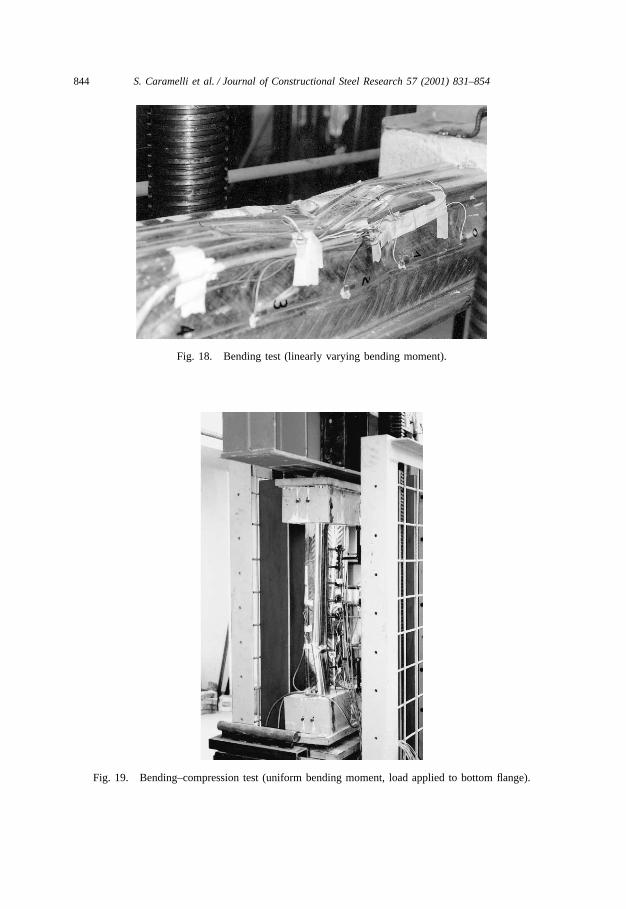
In the second series, pure bending tests and combined bending–compression testswere performed according to the scheme shown in Fig. 13. An increasing displace-ment was applied at the mid-span profile by a vertical hydraulic jack with an electro-hydraulic servo system; in the combined bending–compression tests, another hori-
844 S. Caramelli et al. / Journal of Constructional Steel Research 57 (2001) 831–854
Fig. 18. Bending test (linearly varying bending moment).
Fig. 19. Bending–compression test (uniform bending moment, load applied to bottom flange).

845S. Caramelli et al. / Journal of Constructional Steel Research 57 (2001) 831–854
Fig. 20. Applied load versus strain curves in correspondence with compressed flange, compression testno. 1.
Fig. 21. Deformed shape of the profile axis, test no. 1.

846 S. Caramelli et al. / Journal of Constructional Steel Research 57 (2001) 831–854
Fig. 22. Mode shape I.
Fig. 23. Test results, M–N domain.
zontal jack maintained a constant axial force. Fig. 14 shows the apparatus designedfor such tests, while Table 2summarises all the test results.
Furthermore, pure tension tests were performed on reduced dimension specimensin order to determine the steel’s stress–strain curve. This curve, quite typical of cold-

847S. Caramelli et al. / Journal of Constructional Steel Research 57 (2001) 831–854
Fig. 24. Numerical analysis, restraint and loading condition.
formed steels and in good agreement with Fe E 280 G steel behaviour, is presentedin Fig. 15.
From the test results it was possible to garner important indications about thecollapse mechanisms and post-critical behaviours of the profiles and to define theirresistance domain.
After the local instability phenomena that progressively affects the plane elements(reducing the effective area), collapse comes about suddenly due to overall instabilityof the compressed flange or webs. Interaction between local and overall instabilityphenomena contributes to the failure of the structural element. In the post-criticalphase the profile exhibits a rather good ductility until the buckling of the lateralstiffening elements or the extremities (flange-web fillet and stiffened lips), at whichtime a sudden fall in the applied load occurs.
Figs. 16–19 illustrate some of the post-critical mechanisms revealed through the
848 S. Caramelli et al. / Journal of Constructional Steel Research 57 (2001) 831–854
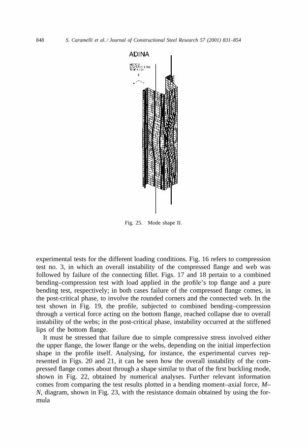
Fig. 25. Mode shape II.
experimental tests for the different loading conditions. Fig. 16 refers to compressiontest no. 3, in which an overall instability of the compressed flange and web wasfollowed by failure of the connecting fillet. Figs. 17 and 18 pertain to a combinedbending–compression test with load applied in the profile’s top flange and a purebending test, respectively; in both cases failure of the compressed flange comes, inthe post-critical phase, to involve the rounded corners and the connected web. In thetest shown in Fig. 19, the profile, subjected to combined bending–compressionthrough a vertical force acting on the bottom flange, reached collapse due to overallinstability of the webs; in the post-critical phase, instability occurred at the stiffenedlips of the bottom flange.
It must be stressed that failure due to simple compressive stress involved eitherthe upper flange, the lower flange or the webs, depending on the initial imperfectionshape in the profile itself. Analysing, for instance, the experimental curves rep-resented in Figs. 20 and 21, it can be seen how the overall instability of the com-pressed flange comes about through a shape similar to that of the first buckling mode,shown in Fig. 22, obtained by numerical analyses. Further relevant informationcomes from comparing the test results plotted in a bending moment–axial force, M–N, diagram, shown in Fig. 23, with the resistance domain obtained by using the for-mula

849S. Caramelli et al. / Journal of Constructional Steel Research 57 (2001) 831–854
Fig. 26. Mode shape III.
NNRd
�M
MRd
�1 (1)
Here, NRd is the pure compression strength and MRd is the bending resistance, bothevaluated by taking into account the effective properties of the profile section andassuming the yield stress equals the nominal values, fy=280 and fy=355 N/mm2.
The design values for the profiles, mainly for high values of the axial force, arenot always safe-sided with respect to the experimental results, confirming the resultsobtained by the first numerical analysis.
4. Numerical analyses
In order to study in detail the phenomena observed during the compression tests,we set up a new, more refined, numerical model able to reproduce the mechanicalbehaviour, as well as the loading conditions and constraints of the tested profile. InFig. 24 the loading and restraint conditions introduced in the model are represented.
Elastic buckling analyses and elastic–plastic non-linear analyses were performed.In the non-linear analysis, in particular, the actual stress–strain law resulting from

850 S. Caramelli et al. / Journal of Constructional Steel Research 57 (2001) 831–854
the experimental tests (Fig. 14) was considered as well as the presence of residualstresses and an initial out of straightness.
Concerning the residual stresses, the membrane stresses were supposed to be onaverage nil, while bending stresses were assumed to follow a linear law through thethickness of the profile, with a maximum of 30% of the yield stress [13,14]. Themaximum out of straightness was assumed to be equal to 0.11 mm [13], imposingthe patterns of the first three mode shapes obtained by the linear buckling analyses,shown in Figs. 22, 25 and 26.
From the results of the numerical analyses, which are in good agreement withthose obtained by the experimental tests, it was possible to draw some further indi-cations. When it is assumed that the initial imperfection follows the shape of oneof the first two buckling modes, collapse essentially involves the top flange of theprofile (collapse shapes I and II, Figs. 27 and 28). Alternatively, if the third shapeis used, the bottom flange also buckles (collapse shape III, Fig. 29). The mechanicalbehaviour of the profile is therefore strongly influenced by the shape and size of theinitial imperfection. Ultimate load, however, as can be deduced from the curves inFig. 30, does not undergo much variation for the different cases.
Useful information on the collapse mechanism can be obtained by plotting, foreach load increment, the normal stress in the transversal section of the profile where
Fig. 27. Collapse shape I.

851S. Caramelli et al. / Journal of Constructional Steel Research 57 (2001) 831–854
Fig. 28. Collapse shape II.
failure occurs. The stresses resulting from the first analysis for the inner and outerfaces of the top flange are shown in Figs. 31 and 32, respectively.
It should be noted that local and overall instability phenomena interact with eachother in determining the profile’s failure, although the four intermediate stiffenersremain effective. In the post-critical phase, however, the two outermost intermediatestiffeners become unstable, bringing about a further reduction in the profile’s load-bearing capacity.
5. Conclusions
A new application for multiple stiffened cold-formed profiles to cylindrical vaultroofing required verification through the methods provided in the current standards.Application of such methods revealed some limitations to their validity.
As Eurocode 3 part 1.3 does not provide for more than two stiffeners per planeelement of the profile, it is not applicable to elements with more complex shapes;in any case, design methods are often based on long and rather “unmanageable”iterative procedures.

852 S. Caramelli et al. / Journal of Constructional Steel Research 57 (2001) 831–854
Fig. 29. Collapse shape III.
Fig. 30. Applied force versus vertical displacement (Z=1000 mm), numerical analyses.

853S. Caramelli et al. / Journal of Constructional Steel Research 57 (2001) 831–854
Fig. 31. Normal stress z–z on top flange’s outer side.
Fig. 32. Normal stress z–z on top flange’s inner side.
Numerical analysis of the profile has moreover revealed that application of themethods foreseen in Eurocode 3 part 1.3 may, in this specific case, lead to resistancevalues that do not guarantee an adequate safety margin.
In performing the design study, we therefore felt compelled to undertake an in-depth theoretical and experimental investigation of the mechanical characteristics ofthe profile used in order to determine its resistance domain, essential to its applicationin current design, as well as other salient information regarding its structuralresponse.
Although the presence of a greater number of intermediate stiffeners increases theprofile’s resistance, it also complicates its mechanical performance. Local instability

854 S. Caramelli et al. / Journal of Constructional Steel Research 57 (2001) 831–854
is accompanied by phenomena of overall instability and distortion, which interactwith each other and together govern the collapse mechanisms and post-critical behav-iour. Development of the different instability phenomena is, in turn, strongly influ-enced by the size and extent of any initial geometrical imperfections.
In general, the results obtained reflect the well-known complexity of the mechan-ical behaviour of cold-formed profiles. Their widespread application, however, pre-supposes the availability of design and verification methods that are at once simpleand reliable. To determine such profiles’ characteristic mechanical parameters andthe general laws governing their behaviour, further study is needed. To this end, thepresent study together with others already underway [7–10], represents a first contri-bution.
Clearly, methods based on determination of the effective width are, in general, noteasy to use and sometimes not reliable. Thus, new, more direct and understandableapproaches need to be developed [11,12], which allow for effectively representingthe essence of the physical phenomena and mechanics in play.
References
[1] Davies JM. Recent research advances in cold-formed steel structures. J Construct Steel Res2000;55:267–88.
[2] Caramelli S, Croce P, Salvatore W. Cylindrical vault roofing using arched corrugated sheeting —numerical analyses. In: Proceedings of XVII Congresso C.T.A., Oct 3–5; Napoli (Italy), 1999.
[3] Catalani L, Cecconi A, Ristori F. Vault shaped roofing using arched corrugated sheeting — standardcomparison and structural design. In: Proceedings of XVII Congresso C.T.A., Oct 3–5; Napoli(Italy), 1999.
[4] CNR 10022/85. Profilati di acciaio formati a freddo, Istruzioni per l’ impiego nelle costruzioni. In:Bollettino Ufficiale (Norme Tecniche), A. XXII, N. 126 [in Italian].
[5] ENV 1993-1.3. Eurocode 3 part 1.3. Supplementary rules for cold formed thin gauge members andsheeting. CEN, European Committee for Standardization.
[6] Weng S, Pekoz T. Compression tests of cold-formed steel columns. J Struct Engng, ASCE1990;116(5):1230–46.
[7] Kwon YB, Hancock GJ. Tests of cold-formed channels with local and distortional buckling. J StructEngng, ASCE 1992;118(7):1786–803.
[8] Papazian RP, Schuster RM, Sommerstein M. Multiple stiffened deck profiles. In: Proceedings of12th International Specialty Conference on Cold-Formed Steel Structures, 1994.
[9] Schafer B. Cold-formed steel behaviour and design: analytical and numerical modelling of elementsand members with longitudinal stiffeners. Dissertation in partial fulfilment of the requirements forthe PhD Degree, Cornell University; 1997.
[10] Schafer B, Pekoz T. Cold-formed steel stiffened elements with multiple longitudinal intermediatestiffeners. J Struct Engng, ASCE 1998;124(10):1175–81.
[11] Schafer BW, Pekoz T. The behaviour and design of longitudinally stiffened thin-walled compressionelements. Thin-Walled Struct J 1997;27(1):65–78.
[12] Schafer B, Pekoz T. Direct strength prediction of cold-formed steel members using numerical elasticbuckling solutions. In: Fourteenth International Specialty Conference on Cold-Formed Steel Struc-tures, Oct 15–16; St Louis (MO), 1998.
[13] Schafer BW, Pekoz T. Computational modelling of cold-formed steel: characterizing geometricimperfections and residual stresses. J Construct Steel Res 1998;47:193–210.
[14] Rondal J. Residual stresses in cold-rolled profiles. Construct Bldg Mater 1987;1(3):150–64.