MULTIPHASE FLUID FLOW MODELLING OF FURNACE … · used to inform boundary conditions in multiphase...
10
12th International Conference on CFD in Oil & Gas, Metallurgical and Process Industries SINTEF, Trondheim, Norway May 30th – June 1st 2017 CFD 2017 521 MULTIPHASE FLUID FLOW MODELLING OF FURNACE TAPHOLES Quinn G. REYNOLDS 1* , Markus W. ERWEE 1 ** 1 MINTEK Pyrometallurgy Division, Randburg, Johannesburg, 2125, SOUTH AFRICA * E-mail: [email protected] ** E-mail: [email protected] ABSTRACT Pyrometallurgical furnaces of many varieties make use of tapholes in order to facilitate the removal of molten process material from inside the vessel. Correct understanding and operation of the taphole is essential for optimal performance of such furnaces. The present work makes use of computational fluid dynamics models generated using the OpenFOAM ® framework in order to study flow behaviour in the taphole system. Single-phase large-eddy simulation models are used to quantify the discharge rate and laminar-turbulent transitions as a function of parameters such as height of material inside the furnace vessel, taphole geometry, and fluid properties. The results are used to inform boundary conditions in multiphase fluid flow models used for prediction of the qualitative behaviour of the free surface in the launder and tapping ladle for selected cases. Keywords: CFD, Pyrometallurgy, Tapholes, Furnace. NOMENCLATURE Greek Symbols Mass density, [kg/m 3 ]. Dynamic viscosity, [kg/m.s]. Latin Symbols D Diameter of taphole, [m]. L Length of taphole [m]. P Pressure, [Pa]. u Velocity, [m/s]. Dimensionless NRe Reynolds number. NL Geometry ratio. NT NEu.√NRe. NEu Euler number. KL Discharge coefficient. INTRODUCTION Many important commodities such as iron and steel, aluminium, ferro-alloys, and precious metals are produced in part using pyrometallurgical furnaces (Jones et al., 2006). The majority of these units make use of tapholes, specially-designed openings in the furnace wall, in order to remove the molten process products from the furnace (Nelson et al., 2016). Depending on the commodity being produced, the furnace may use a single taphole for all material, or separate tapholes for different phases such as slag and metal. Tapholes are typically located in a taphole assembly, a section of the furnace sidewall designed for this purpose. The taphole assembly may consist of several cylindrical or rectangular inserts made of copper, graphite, or refractory material through which the taphole itself runs, mounted within a steel frame which provides structural support and a contact point for water cooling (McDougall, 2014). Figure 1: Tapping in operation on a DC furnace pilot plant, (l) and (m) slag, (r) metal (images courtesy Mintek) After the taphole is opened by lancing or drilling, molten material drains out of the vessel due to differences in hydrostatic pressure (see Figure 1). The rate of drainage is primarily determined by a combination of the inlet geometry and the length of the taphole channel, as well as the physical and thermochemical properties of the material passing through the taphole. Characterisation of the flow behaviour inside the taphole channel is challenging due to the wide variation in physical properties of the fluid phases encountered in furnaces; metals and sulphide mattes tend to be high-density and low-viscosity, while oxide slags are the opposite. Transitions between turbulent and laminar flow may occur during a tap or even within the taphole itself, especially for higher-viscosity materials; such transitions affect not only the discharge rate of material through the taphole but also the mechanical forces on the taphole
Transcript of MULTIPHASE FLUID FLOW MODELLING OF FURNACE … · used to inform boundary conditions in multiphase...

12th International Conference on CFD in Oil & Gas, Metallurgical and Process Industries
SINTEF, Trondheim, Norway
May 30th – June 1st 2017
CFD 2017
521
MULTIPHASE FLUID FLOW MODELLING OF FURNACE TAPHOLES
Quinn G. REYNOLDS1* , Markus W. ERWEE1**
1 MINTEK Pyrometallurgy Division, Randburg, Johannesburg, 2125, SOUTH AFRICA
* E-mail: [email protected] ** E-mail: [email protected]
ABSTRACT
Pyrometallurgical furnaces of many varieties make use of
tapholes in order to facilitate the removal of molten
process material from inside the vessel. Correct
understanding and operation of the taphole is essential for
optimal performance of such furnaces.
The present work makes use of computational fluid
dynamics models generated using the OpenFOAM®
framework in order to study flow behaviour in the
taphole system. Single-phase large-eddy simulation
models are used to quantify the discharge rate and
laminar-turbulent transitions as a function of parameters
such as height of material inside the furnace vessel,
taphole geometry, and fluid properties. The results are
used to inform boundary conditions in multiphase fluid
flow models used for prediction of the qualitative
behaviour of the free surface in the launder and tapping
ladle for selected cases.
Keywords: CFD, Pyrometallurgy, Tapholes, Furnace.
NOMENCLATURE
Greek Symbols
Mass density, [kg/m3].
Dynamic viscosity, [kg/m.s].
Latin Symbols
D Diameter of taphole, [m].
L Length of taphole [m].
P Pressure, [Pa].
u Velocity, [m/s].
Dimensionless
NRe Reynolds number.
NL Geometry ratio.
NT NEu.√NRe.
NEu Euler number.
KL Discharge coefficient.
INTRODUCTION
Many important commodities such as iron and steel,
aluminium, ferro-alloys, and precious metals are
produced in part using pyrometallurgical furnaces (Jones
et al., 2006). The majority of these units make use of
tapholes, specially-designed openings in the furnace
wall, in order to remove the molten process products
from the furnace (Nelson et al., 2016). Depending on the
commodity being produced, the furnace may use a single
taphole for all material, or separate tapholes for different
phases such as slag and metal. Tapholes are typically
located in a taphole assembly, a section of the furnace
sidewall designed for this purpose. The taphole assembly
may consist of several cylindrical or rectangular inserts
made of copper, graphite, or refractory material through
which the taphole itself runs, mounted within a steel
frame which provides structural support and a contact
point for water cooling (McDougall, 2014).
Figure 1: Tapping in operation on a DC furnace pilot plant, (l)
and (m) slag, (r) metal (images courtesy Mintek)
After the taphole is opened by lancing or drilling, molten
material drains out of the vessel due to differences in
hydrostatic pressure (see Figure 1). The rate of drainage
is primarily determined by a combination of the inlet
geometry and the length of the taphole channel, as well
as the physical and thermochemical properties of the
material passing through the taphole. Characterisation of
the flow behaviour inside the taphole channel is
challenging due to the wide variation in physical
properties of the fluid phases encountered in furnaces;
metals and sulphide mattes tend to be high-density and
low-viscosity, while oxide slags are the opposite.
Transitions between turbulent and laminar flow may
occur during a tap or even within the taphole itself,
especially for higher-viscosity materials; such transitions
affect not only the discharge rate of material through the
taphole but also the mechanical forces on the taphole

Q.G. Reynolds and M.W. Erwee
522
surfaces which contribute to erosion and wear, and may
be exacerbated by gas entrainment during tapping (He et
al., 2002).
Upon exiting the taphole, the molten material passes
through an open channel (the tapping launder) and into a
steel or refractory-lined container vessel (the tapping
ladle). The launder and ladle system is a multiphase free
surface flow problem, behaviour of the fluid flow is
highly dependent on the physical properties of the
material being tapped. In practice launders may be angled
both vertically and horizontally in order to reach tapping
ladles located below, ladles may be positioned
incorrectly, and wear on the lining of the launder may
change its shape form the original design. As a result,
substantial splashing and intermixing of the molten phase
with the surrounding air may occur. Although this is
undesirable in the case of reduction smelting or high-
purity product requirements, the degree of contact
between the air and the molten product is generally small
and can be further mitigated by careful launder and ladle
design and operation (Leong et al., 2006).
To date, much research has been conducted in the field
of computational modelling of taphole flow behaviour
using advanced modelling techniques (e.g.
(Kadkhodabeigi et al., 2011) and (Shao et al., 2013)).
However, due to the high resource demands of accurate
computational fluid dynamics modelling, there is
generally a strong focus on specific design problems or
process parameters, using computational fluid dynamics
as a post hoc design analysis or failure forensics tool. In
the present work, the intention is to use computational
modelling as a virtual experimentation platform in order
to gain insight into the behaviour of taphole systems at a
more generalised and simplified level.
FLOW THROUGH THE TAPHOLE – THEORY AND DIMENSIONAL CONSIDERATIONS
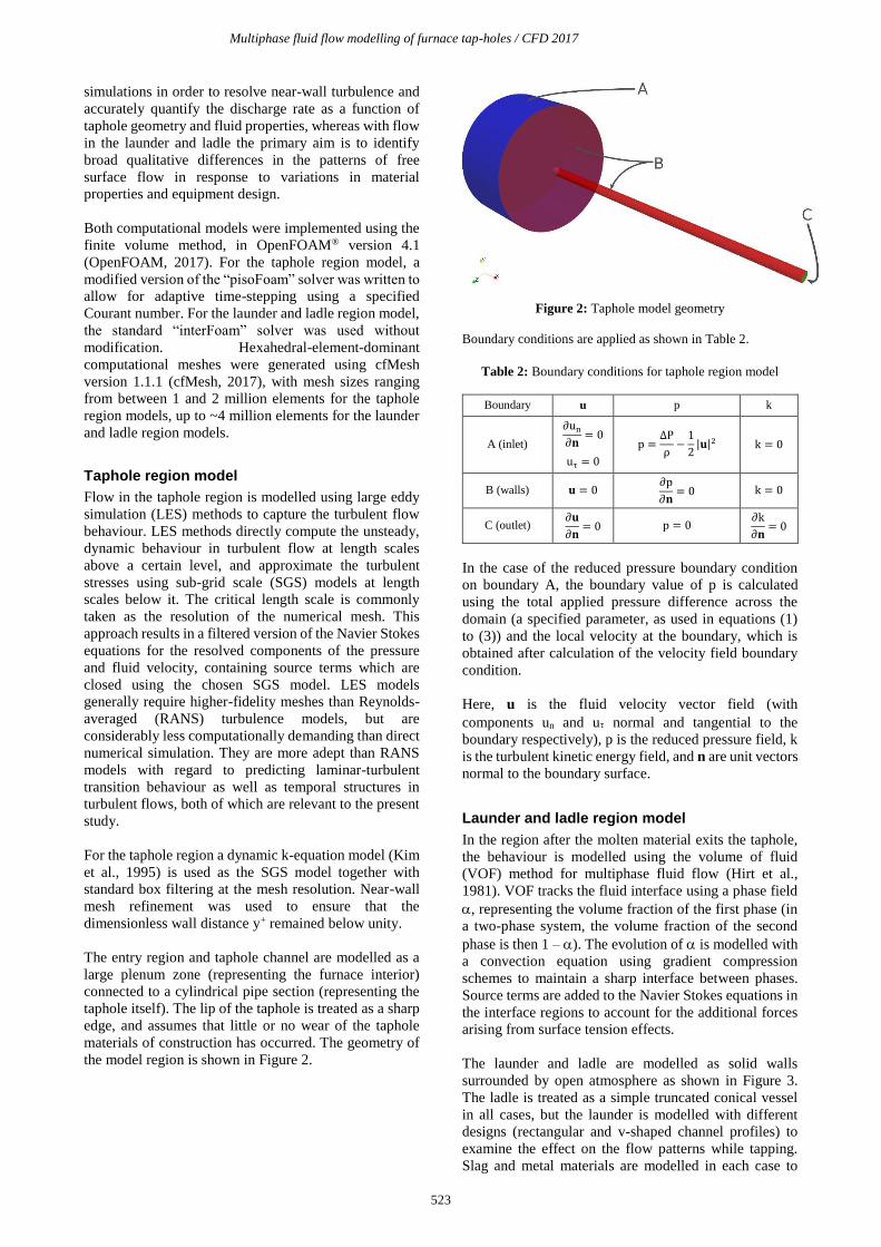
For the taphole region geometry as described in Figure 2,
it is instructive to consider initially a simple theoretical
expression for the fluid flow into and through the taphole.
Similar work has been performed elsewhere (e.g.
(Guthrie, 1992) using the Bernoulli equation to relate the
imposed pressure differential across the taphole to the
flowrate of material through it. This approach results in:
ΔP =ρu2
2+ PP + PE (1)
Where P is the pressure difference between the furnace
interior and exterior as a result of static head of molten
material and any additional forces, is the fluid density,
u is the bulk average velocity of fluid in the taphole, and
PP and PE are the irreversible pressure losses due to
viscous flow inside the taphole channel and friction in the
taphole entry geometry respectively. Bulk velocity of the
fluid in the furnace interior is assumed to be close to zero.
If fully-developed laminar flow in the taphole channel is
assumed, (1) may be written as:
ΔP =32μLu
D2+ (1 + KL)
ρu2
2 (2)
where is the fluid viscosity, L and D are the taphole
length and diameter respectively, and KL is the discharge
coefficient for a given entry geometry (0.5 for sharp-
edged pipe entries, reducing to negligible values for well-
rounded inlets resulting from advanced taphole wear).
Rearranging (2) in terms of dimensionless quantities
yields:
NT2 =
1 + KL
2NRe
2 + 32NLNRe (3)
Here, NRe is the Reynolds number, NL is a simple
geometry ratio, and NT is the product of the Reynolds
number and the square root of the Euler number. By the
principles of dimensional analysis only these three
groups are needed to completely define the problem
regardless of the flow regime; their definitions are shown
in Table 1.
Table 1: Dimensionless groups used to characterise
taphole flow
NRe NL NT
Duρ
μ
L
D D√ρΔP
μ
This particular set of dimensionless groups is preferred
since only one (NRe) is dependent on the fluid velocity,
which is often a poorly-known quantity in tapping
operations. This allows tapping velocity to be represented
explicitly as a function of the taphole design, the
properties of the fluid being tapped, and the applied
pressure.
MODEL DEVELOPMENT
In order to model different aspects of the behaviour of
taphole systems most effectively, several simplifications
were made.
Although the effect of heat transfer and phase change on
the molten material being tapped is an important aspect
of the taphole’s behaviour, this study focuses only on
flow in order to isolate behaviour related to fluid
dynamics. Coupled heat transfer models will be
considered at a later stage but are not within the scope of
the present work.
In addition, the taphole system was divided into two
separate computational models – one covering the single-
phase flow from the furnace interior to the exit point of
the taphole, and another covering the multiphase flow
from the taphole exit through the launder and into the
ladle. The rationale for this approach as opposed to a
single unified model is that different research questions
are posed in the different regions – in flow through the
taphole, it is desirable to perform high fidelity
Multiphase fluid flow modelling of furnace tap-holes / CFD 2017
523
simulations in order to resolve near-wall turbulence and
accurately quantify the discharge rate as a function of
taphole geometry and fluid properties, whereas with flow
in the launder and ladle the primary aim is to identify
broad qualitative differences in the patterns of free
surface flow in response to variations in material
properties and equipment design.
Both computational models were implemented using the
finite volume method, in OpenFOAM® version 4.1
(OpenFOAM, 2017). For the taphole region model, a
modified version of the “pisoFoam” solver was written to
allow for adaptive time-stepping using a specified
Courant number. For the launder and ladle region model,
the standard “interFoam” solver was used without
modification. Hexahedral-element-dominant
computational meshes were generated using cfMesh
version 1.1.1 (cfMesh, 2017), with mesh sizes ranging
from between 1 and 2 million elements for the taphole
region models, up to ~4 million elements for the launder
and ladle region models.
Taphole region model
Flow in the taphole region is modelled using large eddy
simulation (LES) methods to capture the turbulent flow
behaviour. LES methods directly compute the unsteady,
dynamic behaviour in turbulent flow at length scales
above a certain level, and approximate the turbulent
stresses using sub-grid scale (SGS) models at length
scales below it. The critical length scale is commonly
taken as the resolution of the numerical mesh. This
approach results in a filtered version of the Navier Stokes
equations for the resolved components of the pressure
and fluid velocity, containing source terms which are
closed using the chosen SGS model. LES models
generally require higher-fidelity meshes than Reynolds-
averaged (RANS) turbulence models, but are
considerably less computationally demanding than direct
numerical simulation. They are more adept than RANS
models with regard to predicting laminar-turbulent
transition behaviour as well as temporal structures in
turbulent flows, both of which are relevant to the present
study.
For the taphole region a dynamic k-equation model (Kim
et al., 1995) is used as the SGS model together with
standard box filtering at the mesh resolution. Near-wall
mesh refinement was used to ensure that the
dimensionless wall distance y+ remained below unity.
The entry region and taphole channel are modelled as a
large plenum zone (representing the furnace interior)
connected to a cylindrical pipe section (representing the
taphole itself). The lip of the taphole is treated as a sharp
edge, and assumes that little or no wear of the taphole
materials of construction has occurred. The geometry of
the model region is shown in Figure 2.
Figure 2: Taphole model geometry
Boundary conditions are applied as shown in Table 2.
Table 2: Boundary conditions for taphole region model
Boundary u p k
A (inlet)
∂un
∂𝐧= 0
uτ = 0
p =ΔP
ρ−
1
2|𝐮|2 k = 0
B (walls) 𝐮 = 0 ∂p
∂𝐧= 0 k = 0
C (outlet) ∂𝐮
∂𝐧= 0 p = 0
∂k
∂𝐧= 0
In the case of the reduced pressure boundary condition
on boundary A, the boundary value of p is calculated
using the total applied pressure difference across the
domain (a specified parameter, as used in equations (1)
to (3)) and the local velocity at the boundary, which is
obtained after calculation of the velocity field boundary
condition.
Here, u is the fluid velocity vector field (with
components un and u normal and tangential to the
boundary respectively), p is the reduced pressure field, k
is the turbulent kinetic energy field, and n are unit vectors
normal to the boundary surface.
Launder and ladle region model
In the region after the molten material exits the taphole,
the behaviour is modelled using the volume of fluid
(VOF) method for multiphase fluid flow (Hirt et al.,
1981). VOF tracks the fluid interface using a phase field
, representing the volume fraction of the first phase (in
a two-phase system, the volume fraction of the second
phase is then 1 – ). The evolution of is modelled with
a convection equation using gradient compression
schemes to maintain a sharp interface between phases.
Source terms are added to the Navier Stokes equations in
the interface regions to account for the additional forces
arising from surface tension effects.
The launder and ladle are modelled as solid walls
surrounded by open atmosphere as shown in Figure 3.
The ladle is treated as a simple truncated conical vessel
in all cases, but the launder is modelled with different
designs (rectangular and v-shaped channel profiles) to
examine the effect on the flow patterns while tapping.
Slag and metal materials are modelled in each case to

Q.G. Reynolds and M.W. Erwee
524
examine the effect of the physical properties of the
molten phase on the behaviour of the system. A range of
taphole exit velocities is considered based on results
obtained from the taphole region model. Static mesh
refinement is performed in each case by running an initial
simulation at low resolution, and using the resulting
phase field to refine the mesh to higher resolution in areas
where the gas-liquid interface is present. Boundary
conditions used are shown in Table 3.
Figure 3: Geometry of launder and ladle models
Table 3: Boundary conditions for ladle and
launder region model
Boundary u P
D (inlet) 𝐮 = 𝐮0 ∂P
∂𝐧= 0 α = 1
E, F, G (walls)
𝐮 = 0 ∂P
∂𝐧= 0
∂α
∂𝐧= 0
H
(atmosphere)
{
∂un
∂𝐧= 0, uτ = 0
∂𝐮
∂𝐧= 0
{P = P0 −
1
2ρ|𝐮|2
P = P0
{α = 0
∂α
∂𝐧= 0
In the case of the absolute pressure boundary condition
on boundary H, the boundary value of P is calculated
using the specified total atmospheric pressure and the
local velocity at the boundary, which is obtained after
calculation of the velocity field boundary condition.
Here, P is the absolute pressure field, and P0 is
atmospheric pressure in the region around the launder
and ladle. represents the volume fraction of molten
material. At the atmosphere boundary F, it is possible for
fluid to flow both into and out of the domain – for each
field, the first expression is used in the case of inflow, the
second in the case of outflow.
Model parameters
The viscosities, densities and surface tension values of
slags, mattes and metals vary with both composition and
temperature. These properties are often difficult to
measure, due to the extreme temperatures at which these
phases are molten. A detailed summary of the viscosity
and density values for various commodity smelting
operations in given in (Nelson et al., 2016). For iron and
steel production, ferroalloys such as ferrochromium and
ferromanganese, the viscosity of the metal phase at
temperature varies between 0.004 and 0.007 Pa.s. For
mattes (e.g. from copper and nickel smelting operations),
the values can be higher – varying from 0.003 to 0.05 Pa.s
The viscosity of slags from these operations varies
between 0.1 to 1.5 Pa.s across operations, except for
copper smelting where the slag viscosity values are as
low as 0.03 Pa.s. Notably, the viscosity of slags in any
operation can increase dramatically when solids
precipitate from the melt.
Density values vary from 5500 to 7500 kg/m³ for ferrous-
based processes, typically 4200-4500 kg/m³ for mattes.
Slag density values vary between 2600-3200 kg/m³ for
most slags, except for, for example copper and nickel
process slags, which generally slightly higher densities,
roughly 3500 – 4000 kg/m³.
The surface tension values for metals and slags in
pyrometallurgical processes are quite high (when
compared to common fluids). These values vary across
commodities, but is roughly 0.5 N/m for most common
slags, mattes and metals (Tanaka et al., 2014).
In terms of the physical design and operation parameters
of the taphole region, typical lengths and diameters for
slag, metal, and matte tapholes have been reported in
several sources, for example (Nelson et al., 2016), (van
Beek et al., 2014), and (Nolet, 2014). A summary of the
industrial data is shown in Table 4. Although the internal
furnace pressure in the case of certain processes such as
blast furnaces can be extremely high (up to 5 bar (Nelson
et al., 2016)), in open-bath smelting furnaces the primary
source of the pressure is most often the head of molten
material above the level of the taphole. Typical values
across several different processes are reported in (Nelson
et al., 2016) and summarised in Table 5.
Table 4: Geometry parameters for industrial furnace tapholes
Material Taphole diameter Taphole length
Slag 0.04 – 0.1 m < 1.3 m
Matte 0.04 – 0.1 m 1 – 1.5 m
Metal 0.04 – 0.07 m 1 – 1.5 m
Table 5: Head of molten material above tapholes for slag and
metal/matte systems
Material Above slag
taphole
Above metal/matte
taphole
Slag 0.2 – 1 m 0.4 – 2 m
Metal/matte - 0.15 – 0.6 m
In order to demonstrate the use of the multiphase flow
model of the launder and ladle region, dimensions based
on pilot-scale DC furnace equipment in use at Mintek
were selected. Two different launder cross sections, a
square channel profile and a v-shaped channel profile,
were studied at different flowrates of slag and metal
material to determine their impact on the flow pattern into
the ladle. Dimensions of the model system are shown in
Table 6.

Multiphase fluid flow modelling of furnace tap-holes / CFD 2017
525
Table 6: Geometry parameters for launder and ladle models
Parameter Value Parameter Value
Taphole
diameter 0.03 m Ladle diameter 1 m
Launder
length 0.4 m Ladle height 0.75 m
Launder
width 0.2 m
Launder height
above ladle 0.2 m
Launder
inclination 5
RESULTS AND DISCUSSION
Taphole region models
In order to study a broad range of typical taphole
conditions and designs representative of most electric
smelting processes, a set of simulations was executed to
cover the ranges 500 < NT < 500000, and 10 < NL < 50.
This was achieved in the computational model by fixing
taphole diameter (0.02 m), fluid density (7000 kg/m3),
and applied pressure (89286 Pa), and calculating the
required taphole length and fluid viscosity in each case
based on the desired values of NT and NL using the
expressions in Table 1.
Once the initial conditions had decayed sufficiently
(typically after 1 s of simulation time), a time- and area-
averaged velocity at the taphole outlet was computed and
used to calculate NRe. The laminar or turbulent nature of
the flow was assessed using the relative variability in
time of the velocity field at the outlet – this was
calculated by finding the difference between the
minimum and maximum velocity values at the taphole
centreline over the final 0.2 s of simulation time divided
by the average outlet velocity over the same time period.
A total of 32 separate cases were simulated using the
sharp-edged entry geometry shown in Figure 2, each
taking between 10 and 20 hours of wall time on 16 Intel
Xeon CPUs.
For model validation purposes, the simulation results
were compared to the predictions of equation (3) in the
laminar flow region. This is shown in Figure 4. The
agreement in both qualitative trends and values is fairly
good, with the computational model under-predicting
slightly relative to (3). This is expected since (3) assumes
that the flow in the taphole is fully developed along its
entire length, whereas in reality there will be an entrance
length over which the wall boundary layer expands
before full Hagen-Poisiuelle flow is reached. In this entry
region, the wall shear forces are higher and will therefore
restrict the flow to a greater degree, resulting in lower
flowrates than those predicted by (3).
Figure 4: Model validation against equation (3)
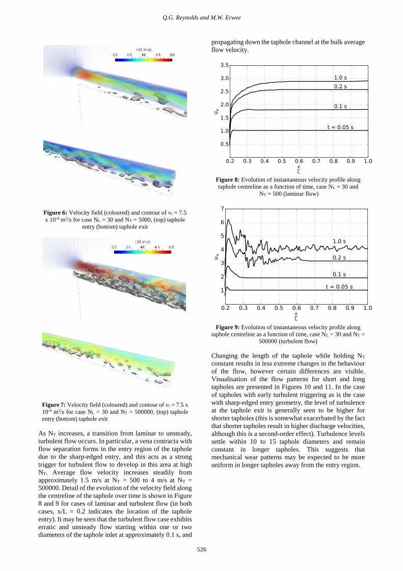
Visualisations of the instantaneous flow patterns in and
around the taphole are presented in Figures 5 to 7, for
cases in which the value of NL was fixed at 30 and the
value of NT was changed. All visualisations are shown at
the end of the simulation, time = 1 s. The upper section
of each image shows the velocity profile through the 3D
volume, and the lower section shows a contour plot of
turbulent viscosity t.
Figure 5: Velocity field (coloured) and contour of t = 7.5 x
10-6 m2/s for case NL = 30 and NT = 500, (top) taphole entry
(bottom) taphole exit
Q.G. Reynolds and M.W. Erwee
526
Figure 6: Velocity field (coloured) and contour of t = 7.5
x 10-6 m2/s for case NL = 30 and NT = 5000, (top) taphole
entry (bottom) taphole exit
Figure 7: Velocity field (coloured) and contour of t = 7.5 x
10-6 m2/s for case NL = 30 and NT = 500000, (top) taphole
entry (bottom) taphole exit
As NT increases, a transition from laminar to unsteady,
turbulent flow occurs. In particular, a vena contracta with
flow separation forms in the entry region of the taphole
due to the sharp-edged entry, and this acts as a strong
trigger for turbulent flow to develop in this area at high
NT. Average flow velocity increases steadily from
approximately 1.5 m/s at NT = 500 to 4 m/s at NT =
500000. Detail of the evolution of the velocity field along
the centreline of the taphole over time is shown in Figure
8 and 9 for cases of laminar and turbulent flow (in both
cases, x/L = 0.2 indicates the location of the taphole
entry). It may be seen that the turbulent flow case exhibits
erratic and unsteady flow starting within one or two
diameters of the taphole inlet at approximately 0.1 s, and
propagating down the taphole channel at the bulk average
flow velocity.
Figure 8: Evolution of instantaneous velocity profile along
taphole centreline as a function of time, case NL = 30 and
NT = 500 (laminar flow)
Figure 9: Evolution of instantaneous velocity profile along
taphole centreline as a function of time, case NL = 30 and NT =
500000 (turbulent flow)
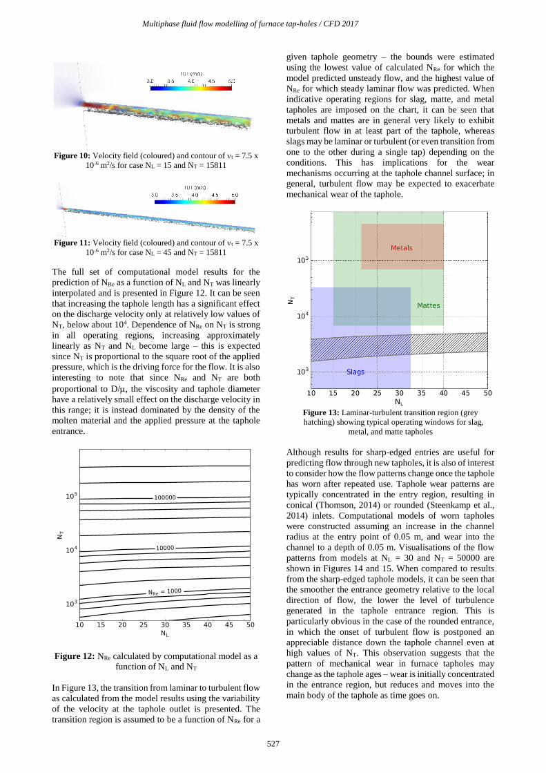
Changing the length of the taphole while holding NT
constant results in less extreme changes in the behaviour
of the flow, however certain differences are visible.
Visualisation of the flow patterns for short and long
tapholes are presented in Figures 10 and 11. In the case
of tapholes with early turbulent triggering as is the case
with sharp-edged entry geometry, the level of turbulence
at the taphole exit is generally seen to be higher for
shorter tapholes (this is somewhat exacerbated by the fact
that shorter tapholes result in higher discharge velocities,
although this is a second-order effect). Turbulence levels
settle within 10 to 15 taphole diameters and remain
constant in longer tapholes. This suggests that
mechanical wear patterns may be expected to be more
uniform in longer tapholes away from the entry region.
Multiphase fluid flow modelling of furnace tap-holes / CFD 2017
527
Figure 10: Velocity field (coloured) and contour of t = 7.5 x
10-6 m2/s for case NL = 15 and NT = 15811
Figure 11: Velocity field (coloured) and contour of t = 7.5 x
10-6 m2/s for case NL = 45 and NT = 15811
The full set of computational model results for the
prediction of NRe as a function of NL and NT was linearly
interpolated and is presented in Figure 12. It can be seen
that increasing the taphole length has a significant effect
on the discharge velocity only at relatively low values of
NT, below about 104. Dependence of NRe on NT is strong
in all operating regions, increasing approximately
linearly as NT and NL become large – this is expected
since NT is proportional to the square root of the applied
pressure, which is the driving force for the flow. It is also
interesting to note that since NRe and NT are both
proportional to D/, the viscosity and taphole diameter
have a relatively small effect on the discharge velocity in
this range; it is instead dominated by the density of the
molten material and the applied pressure at the taphole
entrance.
Figure 12: NRe calculated by computational model as a
function of NL and NT
In Figure 13, the transition from laminar to turbulent flow
as calculated from the model results using the variability
of the velocity at the taphole outlet is presented. The
transition region is assumed to be a function of NRe for a
given taphole geometry – the bounds were estimated
using the lowest value of calculated NRe for which the
model predicted unsteady flow, and the highest value of
NRe for which steady laminar flow was predicted. When
indicative operating regions for slag, matte, and metal
tapholes are imposed on the chart, it can be seen that
metals and mattes are in general very likely to exhibit
turbulent flow in at least part of the taphole, whereas
slags may be laminar or turbulent (or even transition from
one to the other during a single tap) depending on the
conditions. This has implications for the wear
mechanisms occurring at the taphole channel surface; in
general, turbulent flow may be expected to exacerbate
mechanical wear of the taphole.
Figure 13: Laminar-turbulent transition region (grey
hatching) showing typical operating windows for slag,
metal, and matte tapholes
Although results for sharp-edged entries are useful for
predicting flow through new tapholes, it is also of interest
to consider how the flow patterns change once the taphole
has worn after repeated use. Taphole wear patterns are
typically concentrated in the entry region, resulting in
conical (Thomson, 2014) or rounded (Steenkamp et al.,
2014) inlets. Computational models of worn tapholes
were constructed assuming an increase in the channel
radius at the entry point of 0.05 m, and wear into the
channel to a depth of 0.05 m. Visualisations of the flow
patterns from models at NL = 30 and NT = 50000 are
shown in Figures 14 and 15. When compared to results
from the sharp-edged taphole models, it can be seen that
the smoother the entrance geometry relative to the local
direction of flow, the lower the level of turbulence
generated in the taphole entrance region. This is
particularly obvious in the case of the rounded entrance,
in which the onset of turbulent flow is postponed an
appreciable distance down the taphole channel even at
high values of NT. This observation suggests that the
pattern of mechanical wear in furnace tapholes may
change as the taphole ages – wear is initially concentrated
in the entrance region, but reduces and moves into the
main body of the taphole as time goes on.

Q.G. Reynolds and M.W. Erwee
528
Figure 14: Velocity field (coloured) and contour of
t = 7.5 x 10⁻⁶ m2/s for case NL = 30 and NT = 50000
with conical entrance, (top) taphole entry (bottom)
taphole exit
Figure 15: Velocity field (coloured) and contour of
t = 7.5 x 10⁻⁶ m2/s for case NL = 30 and NT = 50000
with rounded entrance, (bottom) taphole entry (top)
taphole exit
Although there are considerable qualitative differences in
the flow patterns and turbulence onset, the quantitative
differences in flow velocity are relatively small for
different entry configurations. Figure 16 shows a
comparison of the sharp-edged entry results with those
from conical and rounded entry models.
Figure 16: NRe calculated by computational model as a
function of NT at NL = 30, for different entry geometries
It can be seen that the tapping velocities match within 10-
20 % across a wide range of NT for all geometries tested,
although more comprehensive study is recommended to
verify this result.
Ladle and launder region models
The results from the taphole region model determine
appropriate ranges on the taphole exit velocity, which is
required as an input boundary condition for the launder
and ladle region model – in the case of a pilot-scale
furnace as modelled here, exit velocities between 1 and 3
m/s were applied. For the liquid phase being tapped, both
slag ( = 0.1 Pa.s, = 2500 kg/m3) and metal ( = 0.005
Pa.s, = 7000 kg/m3) materials were used. For the
surrounding gas phase, the properties of air were used.
Results comparing different materials and flowrates for
the rectangular launder design are shown in Figures 17 to
20, in all cases at time 4 s after taphole opening. The
contour of = 0.1 is used to show the liquid surface, and
coloured according to the local velocity field.

Multiphase fluid flow modelling of furnace tap-holes / CFD 2017
529
Figure 17: Rectangular
profile launder,
slag tapping at 1 m/s
Figure 18: Rectangular
profile launder,
slag tapping at 3 m/s
Figure 19: Rectangular
launder profile,
metal tapping at 1 m/s
Figure 20: Rectangular
launder profile,
metal tapping at 3 m/s
At low flowrates, the tapping stream is generally well
contained within the launder channel with minimal
splashing before exiting into the ladle. At high flowrates
(typical of when the taphole is newly opened) it is clear
that this particular launder design is too short – the
tapping stream catches the edge of the launder and
spreads the tapped material out into a fan shape as it
enters the ladle. This would not be an optimal
configuration for tapping metal, as the increased surface
area may result in undesirable re-oxidation of the
material by the surrounding air as it enters the ladle.
Comparing different materials, it can be seen that in the
case of metal the flow tends to separate out into smaller
droplets and streams than in the case of slag; it is likely
that this is related to the lower viscosity of molten metals.
The flow patterns at low tapping velocities are
particularly different, due to the development of open-
channel flow patterns in the launder in addition to the
free-surface flow as the material exits into the ladle.
Results comparing a simple variation on the launder
design are shown in Figures 21 to 24. Flow behaviour at
a fixed tapping velocity (2 m/s) is shown in all cases, with
visualisations performed at 4 s after the taphole was
opened. The contour of = 0.1 is used to show the liquid
surface, and coloured according to the local velocity
field.
Figure 21: Rectangular
launder profile,
slag tapping at 2 m/s
Figure 22: V-shaped
launder profile,
slag tapping at 2 m/s
Figure 23: Rectangular
launder profile,
metal tapping at 2 m/s
Figure 24: V-shaped
launder profile,
metal tapping at 2 m/s
Changing the cross-sectional shape of the launder has a
significant impact on the shape and structure of the flow
regardless of the material being tapped. In the case of the
v-shaped launder, the channel flow is kept contained in a
narrower cross-section as it traverses the launder,
resulting in a more contained stream flowing into the
ladle. This results in less break-up of the stream into
droplets, keeping the surface area exposed to air lower.
The intense, directed flow of the stream into the ladle
may however cause high localised heat transfer and
mechanical wear of the ladle lining – this would have to
be managed carefully to avoid premature ladle failure.
CONCLUSIONS
Characterisation of the flow behaviour in furnace taphole
systems is a complex subject. Due to the practical
challenges associated with handling of molten materials
at high temperatures, computational modelling can be
used very effectively as a complement to experimental
work in this area. Development of preliminary
computational models of the fluid flow behaviour both
inside the taphole and after the material exits it have been
successful, and study of a range of operating parameters
and designs was conducted.
The taphole region models demonstrated that for typical
material properties and taphole geometries, the nature of
the flow inside the taphole can be expected to be
turbulent for metals and mattes, but may be laminar or
turbulent for slags depending on conditions.
Quantification of the taphole exit velocities in terms of
dimensionless parameters was obtained, with
dependence of NRe on NT being much stronger than on
NL. The effect of taphole entrance geometry on
turbulence onset and flow patterns in the taphole channel
was found to be appreciable, however, the exit velocities
were not particularly sensitive to this change.

Q.G. Reynolds and M.W. Erwee
530
The results from the taphole region model were used as
boundary conditions for multiphase flow models of the
launder and ladle outside the furnace. The scope of this
work was limited to comparing the flow behaviour in a
simple design at pilot-plant furnace scale. It was found
that differences in flow patterns between slag and metal
were exaggerated at low tapping velocities, with metal
flows tending to break up into smaller droplets and
streams. Launder channel shape also had a large effect on
the nature of the free surface flow between the launder
and the ladle, suggesting that proper launder design and
maintenance is critical for repeatable tapping flow
behaviour.
This work is intended to be a preliminary starting point
for computational modelling of taphole flow behaviour,
and as such, there is considerable scope for further
research in this area. In the taphole region, more detailed
studies of fluid dynamics in the taphole channel using
LES or direct numerical simulation models which
include the effect of taphole wear on geometry and
surface roughness would be of value. In the launder and
ladle region, evolution of the model into a virtual
prototype capable of comparative performance testing of
various designs is anticipated. In all cases the impact of
coupling additional phenomena (in particular heat
transfer and phase change) to the flow model should be
investigated further, and ultimately integrated into the
thermal design of the taphole assembly.
ACKNOWLEDGEMENTS
This paper is published by permission of Mintek. The
CSIR Centre for High Performance Computing provided
computational resources for execution of all modelling
work. The authors gratefully acknowledge useful
interactions with Lloyd Nelson and Rodney Hundermark
(Anglo American plc), and Joalet Steenkamp (Mintek).
REFERENCES
JONES, R.T. and CURR, T.R. (2006). “Pyrometallurgy at
Mintek”, Proc. SAIMM Southern African Pyrometallurgy 2006,
Johannesburg, South Africa, p 127.
NELSON, L.R. and HUNDERMARK, R.J. (2016). “’The tap-
hole’ – key to furnace performance”, J. SAIMM, 116(5), p 465.
MCDOUGALL, I. (2014). “Water cooled tap-hole blocks”,
Proc. SAIMM Furnace Tapping Conference 2014,
Muldersdrift, South Africa, p 183.
HE, Q., ZULLI, P., TANZIL, F., LEE, B., DUNNING, J., and
EVANS, G. (2002). “Flow characteristics of a blast furnace
taphole stream and its effects on trough refractory wear”, ISIJ,
42(3), p 235.
LEONG, B. and JOUBERT, H. (2006). “Innovative and safe
copper launder design”, Proc. SAIMM Southern African
Pyrometallurgy 2006, Johannesburg, South Africa, p 385.
KADKHODABEIGI, M., TVEIT, H., and JOHANSEN, S.T.
(2011). “Modelling the tapping process in submerged arc
furnaces used in high silicon alloys production”, ISIJ, 51(2), p
193.
SHAO, L. and SAXEN, H. (2013). “A simulation study of two-
liquid flow in the taphole of the blast furnace”, ISIJ, 53(6), p
988.
GUTHRIE, R.I.L. (1992). “Engineering in process metallurgy”,
Oxford University Press, Oxford, United Kingdom.
OpenFOAM (2017). https://www.openfoam.org/, accessed
10/02/2017.
cfMesh (2017). http://cfmesh.com/, accessed 10/02/2017.
KIM, W.-W. and MENON, S. (1995). “A new dynamic one-
equation subgrid-scale model for large eddy simulations”, Proc.
AIAA 33rd Aerospace Sciences Meeting and Exhibit, Reno NV,
USA, paper 1995-0356.
HIRT, C.W. and NICHOLS, B.D. (1981). "Volume of fluid
(VOF) method for the dynamics of free boundaries", J. Comput.
Phys., 39(1), p 201.
TANAKA, T. and SCHELLER, P.R. “Interfacial Phenomena in
High Temperature Metallurgy”, Chapter 1 in Treatise on
Process Metallurgy Volume 2: Process Phenomena, edited by
Seetharaman, S., McLean, A., Guthrie, R. and Sridhar, S.,
Elsevier, 2014, pp.46-50.
VAN BEEK, W.S.B., GOFF, T.J., NEL, P.E., and REX, E.
(2014). “An overview of the design, operation, and
maintenance practices relating to tap-hole management of a
PGM smelting furnace”, Proc. SAIMM Furnace Tapping
Conference 2014, Muldersdrift, South Africa, p 113.
NOLET, I. (2014). “Tapping of PGM-Ni mattes: an industry
survey”, Proc. SAIMM Furnace Tapping Conference 2014,
Muldersdrift, South Africa, p 223.
THOMSON, L. (2014). “Monitoring, repair, and safety
practices for electric furnace matte tapping”, Proc. SAIMM
Furnace Tapping Conference 2014, Muldersdrift, South Africa,
p 87.
STEENKAMP, J.D, GOUS, J.P., PISTORIUS, P.C.,
TANGSTAD, M., and ZIETSMAN, J.H. (2014). “Wear
analysis of a tap-hole from a SiMn production furnace”, Proc.
SAIMM Furnace Tapping Conference 2014, Muldersdrift,
South Africa, p 51.