Multiphase Flow and Heat Transfer - IIT Patnasudheer/ME546/11 Multiphase Flow - Flow Regimes.… ·...
42
Transcript of Multiphase Flow and Heat Transfer - IIT Patnasudheer/ME546/11 Multiphase Flow - Flow Regimes.… ·...
Two Phase Flow
Reference:
S. Mostafa Ghiaasiaan, Two-Phase Flow, Boiling and Condensation,
Cambridge University Press.
http://dx.doi.org/10.1017/CBO9780511619410
Two Phase Flow - Introduction
• Two phase flows are commonly found in ordinary life and in
industrial processes
• Gas-liquid flow also occurs in boiling and condensation
operations
• Inside pipelines which carry oil or gas alone, but which actually
carry a mixture of oil and gas.
Two Phase Flow – How They Differs
Single phase flow
Laminar, transition, and turbulent
When the flow regime changes from laminar to turbulent
the personality of the fluid completely changes
the phenomena governing the transport processes change
Two phase flow
Similar situation
However, there is a multitude of flow regimes
The behavior of a gas–liquid mixture depends strongly on the
flow regimes.
Methods for predicting the major flow regimes are required,
for the modeling and analysis of two-phase flow systems
Two Phase Flow Patterns
Morphological variations
1. Δρ between phases. Respond differently to gravity and
centrifugal forces
2. The deformability of the gas-liquid interphase that often
results in incessant coalescence and breakup processes
3. Surface tension forces, maintains one phase dispersal
Two Phase Flow Patterns
Morphological variations
1. Δρ between phases. Respond differently to gravity and
centrifugal forces
2. The deformability of the gas-liquid interphase that often
results in incessant coalescence and breakup processes
3. Surface tension forces, maintains one phase dispersal
Flow regimes and their ranges of occurrence are sensitive to
• fluid properties, system configuration/and orientation, size
scale of the system, occurrence of phase change, etc.
• Most widely used: steady-state and adiabatic air-water and
steam-water in uniform-cross-section long vertical pipes, or
large vertical rod bundles with uniform inlet conditions
Basic Definitions
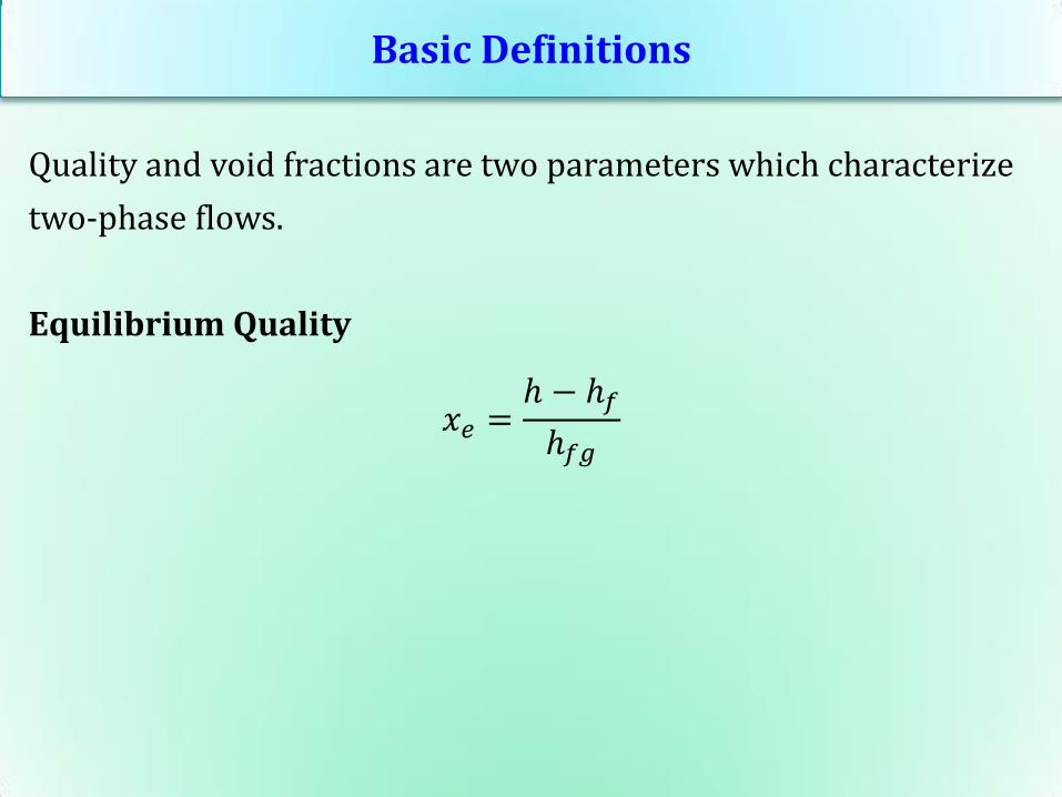
Quality and void fractions are two parameters which characterize
two-phase flows.
Equilibrium Quality
𝑥𝑒 =ℎ − ℎ𝑓
ℎ𝑓𝑔
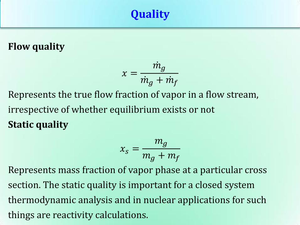
Quality
Flow quality
𝑥 =𝑚 𝑔
𝑚 𝑔 +𝑚 𝑓
Represents the true flow fraction of vapor in a flow stream,
irrespective of whether equilibrium exists or not
Static quality
𝑥𝑠 =𝑚𝑔
𝑚𝑔 +𝑚𝑓
Represents mass fraction of vapor phase at a particular cross
section. The static quality is important for a closed system
thermodynamic analysis and in nuclear applications for such
things are reactivity calculations.
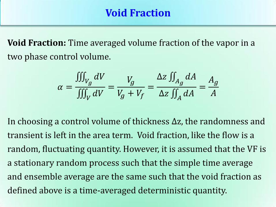
Void Fraction
Void Fraction: Time averaged volume fraction of the vapor in a
two phase control volume.
𝛼 = 𝑑𝑉
𝑉𝑔
𝑑𝑉𝑉
=𝑉𝑔
𝑉𝑔 + 𝑉𝑓=Δ𝑧 𝑑𝐴
𝐴𝑔
Δ𝑧 𝑑𝐴𝐴
=𝐴𝑔
𝐴
In choosing a control volume of thickness Δz, the randomness and
transient is left in the area term. Void fraction, like the flow is a
random, fluctuating quantity. However, it is assumed that the VF is
a stationary random process such that the simple time average
and ensemble average are the same such that the void fraction as
defined above is a time-averaged deterministic quantity.
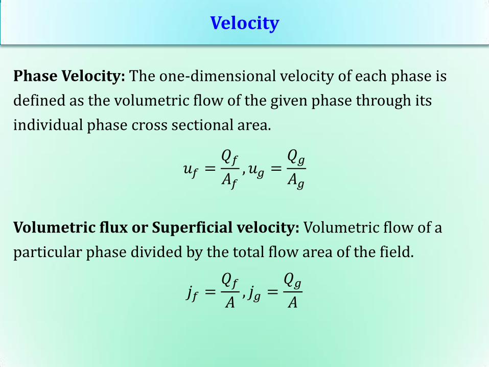
Velocity
Phase Velocity: The one-dimensional velocity of each phase is
defined as the volumetric flow of the given phase through its
individual phase cross sectional area.
𝑢𝑓 =𝑄𝑓𝐴𝑓
, 𝑢𝑔 =𝑄𝑔
𝐴𝑔
Volumetric flux or Superficial velocity: Volumetric flow of a
particular phase divided by the total flow area of the field.
𝑗𝑓 =𝑄𝑓𝐴, 𝑗𝑔 =
𝑄𝑔
𝐴
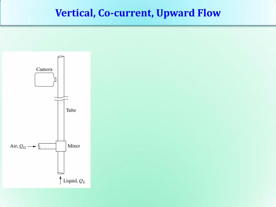
Vertical, Co-current, Upward Flow
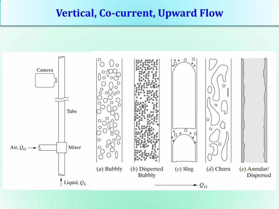
Vertical, Co-current, Upward Flow
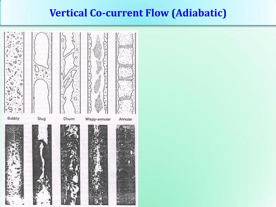
Vertical Co-current Flow (Adiabatic)
Vertical Co-current Flow (Adiabatic)
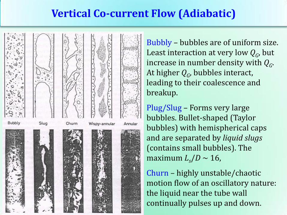
Bubbly – bubbles are of uniform size. Least interaction at very low QG, but increase in number density with QG. At higher QG, bubbles interact, leading to their coalescence and breakup.
Plug/Slug – Forms very large bubbles. Bullet-shaped (Taylor bubbles) with hemispherical caps and are separated by liquid slugs (contains small bubbles). The maximum Ls/D ~ 16,
Churn – highly unstable/chaotic motion flow of an oscillatory nature: the liquid near the tube wall continually pulses up and down.

Vertical Co-current Flow (Adiabatic)
Wispy annular - The liquid in the film is aerated by small gas bubbles and the entrained liquid phase appears as large droplets which have agglomerated into long irregular filaments or wisps.
Annular – liquid travels partly as an annular film on the walls of the tube and partly as small drops distributed in the gas which flows in the center of the tube
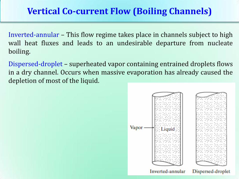
Vertical Co-current Flow (Boiling Channels)
Inverted-annular – This flow regime takes place in channels subject to high wall heat fluxes and leads to an undesirable departure from nucleate boiling.
Dispersed-droplet – superheated vapor containing entrained droplets flows in a dry channel. Occurs when massive evaporation has already caused the depletion of most of the liquid.
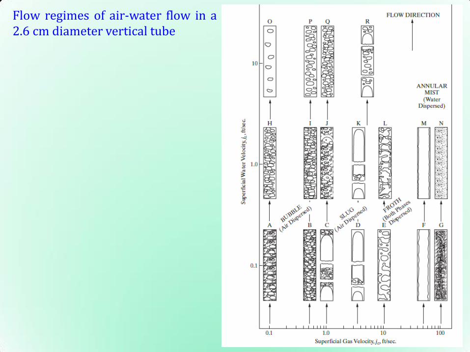
Flow regimes of air-water flow in a 2.6 cm diameter vertical tube
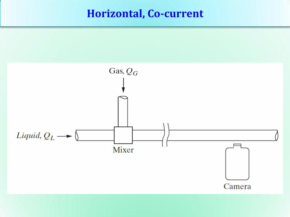
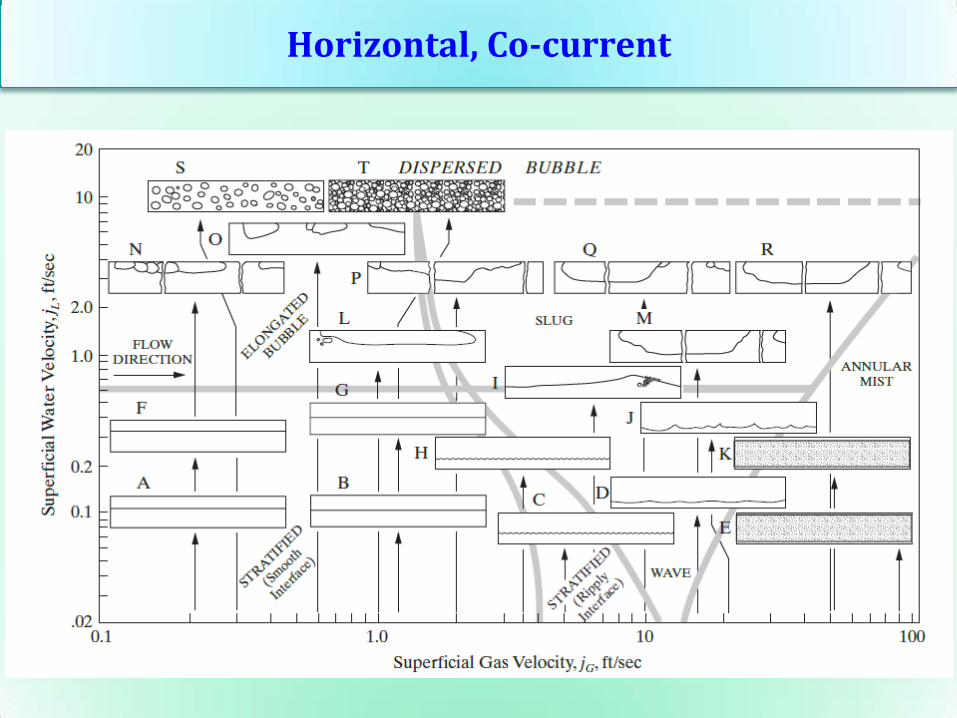
Horizontal, Co-current
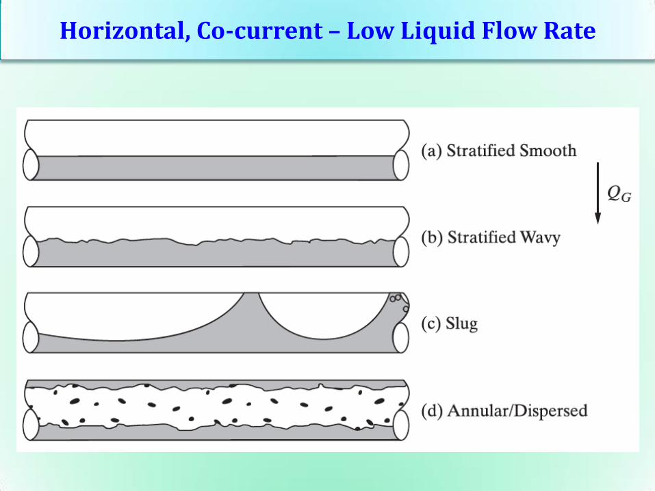
Horizontal, Co-current – Low Liquid Flow Rate

Horizontal, Co-current – High Liquid Flow Rate
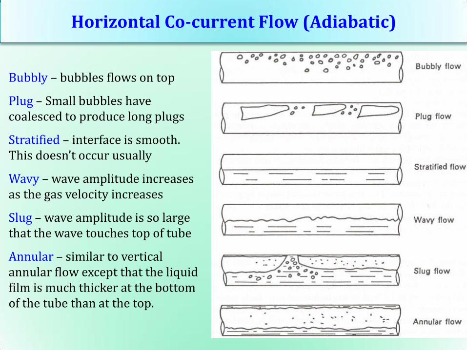
Horizontal Co-current Flow (Adiabatic)
Bubbly – bubbles flows on top
Plug – Small bubbles have coalesced to produce long plugs
Stratified – interface is smooth. This doesn’t occur usually
Wavy – wave amplitude increases as the gas velocity increases
Slug – wave amplitude is so large that the wave touches top of tube
Annular – similar to vertical annular flow except that the liquid film is much thicker at the bottom of the tube than at the top.
Horizontal, Co-current
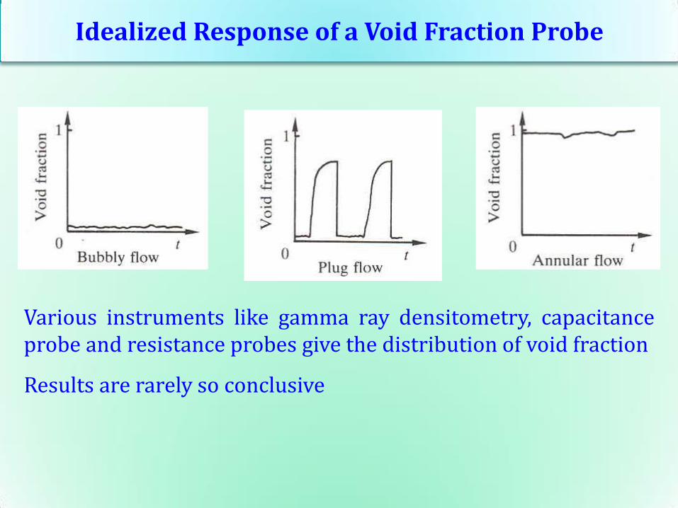
Idealized Response of a Void Fraction Probe
Various instruments like gamma ray densitometry, capacitance probe and resistance probes give the distribution of void fraction
Results are rarely so conclusive

Summary
1. Flow regimes and conditions depends on
• geometry: size, shape, aspect ratio of channel, flow
disturbances
• liquid properties: σ, μ, ρl/ρg
Summary
1. Flow regimes and conditions depends on
• geometry: size, shape, aspect ratio of channel, flow
disturbances
• liquid properties: σ, μ, ρl/ρg
2. Basic regimes occur in all system configurations.
Summary
1. Flow regimes and conditions depends on
• geometry: size, shape, aspect ratio of channel, flow
disturbances
• liquid properties: σ, μ, ρl/ρg
2. Basic regimes occur in all system configurations.
3. There could be multitude of subtle flow regimes.
Summary
1. Flow regimes and conditions depends on
• geometry: size, shape, aspect ratio of channel, flow
disturbances
• liquid properties: σ, μ, ρl/ρg
2. Basic regimes occur in all system configurations.
3. There could be multitude of subtle flow regimes.
4. The regime change boundaries are generally difficult to define
due to the occurrence of extensive “transitional” regimes
5. Bubbly, plug/slug, churn, annular flows also occur in
minichannels (100 μm ≤ D ≤ 1 mm)
6. Regimes in phase change are significantly different from
adiabatic
Flow Pattern Maps
Flow pattern maps are 2D graphs to separate the space into areas
corresponding to the various flow patterns
Hewitt and Roberts Map – Vertical upflow in a tube
Baker Map – Horizontal flow
Taitel and Dukler Map – Horizontal flow
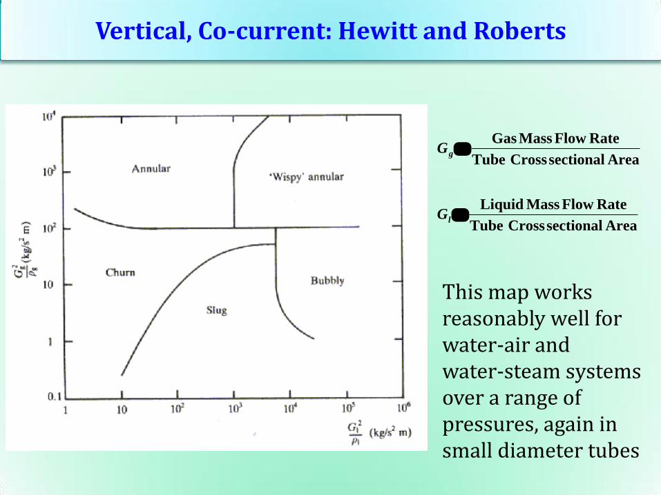
Vertical, Co-current: Hewitt and Roberts
AreasectionalCrossTube
RateFlowMassGasgG
AreasectionalCrossTube
RateFlowMassLiquidlG
This map works reasonably well for water-air and water-steam systems over a range of pressures, again in small diameter tubes
Baker’s Map (1954) - Modified Scott (1963)
• One of the earliest flow pattern maps for horizontal adiabatic
flow
• Developed based on air-water data
• Identifies stratified, plug, slug, wavy, annular, bubbly flow
patterns
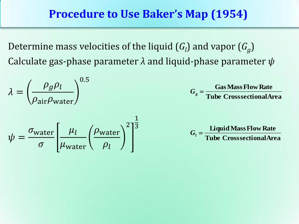
Procedure to Use Baker’s Map (1954)
Determine mass velocities of the liquid (Gl) and vapor (Gg)
Calculate gas-phase parameter λ and liquid-phase parameter ψ
𝜆 =𝜌𝑔𝜌𝑙
𝜌air𝜌water
0.5
𝜓 =𝜎water
𝜎
𝜇𝑙𝜇water
𝜌water
𝜌𝑙
213
AreasectionalCrossTube
RateFlowMassGasgG
AreasectionalCrossTube
RateFlowMassLiquidlG
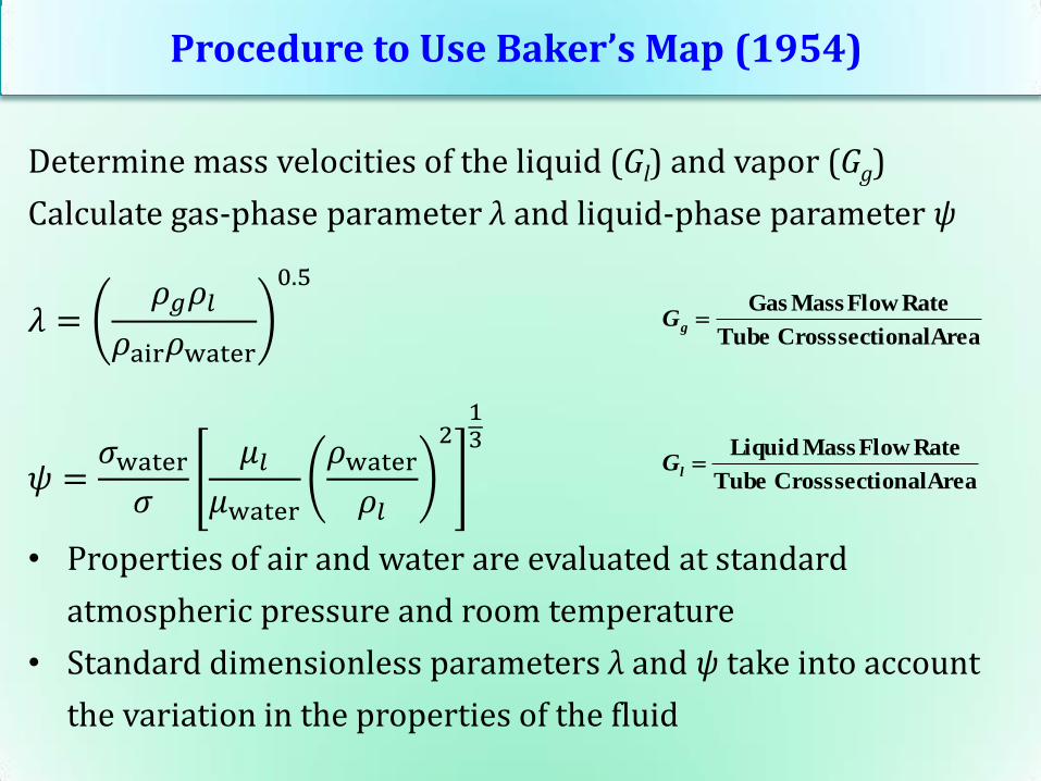
Procedure to Use Baker’s Map (1954)
Determine mass velocities of the liquid (Gl) and vapor (Gg)
Calculate gas-phase parameter λ and liquid-phase parameter ψ
𝜆 =𝜌𝑔𝜌𝑙
𝜌air𝜌water
0.5
𝜓 =𝜎water
𝜎
𝜇𝑙𝜇water
𝜌water
𝜌𝑙
213
• Properties of air and water are evaluated at standard
atmospheric pressure and room temperature
• Standard dimensionless parameters λ and ψ take into account
the variation in the properties of the fluid
AreasectionalCrossTube
RateFlowMassGasgG
AreasectionalCrossTube
RateFlowMassLiquidlG

Horizontal, Co-current: Baker (1954)
Works for R12 in 8 mm diameter horizontal tube
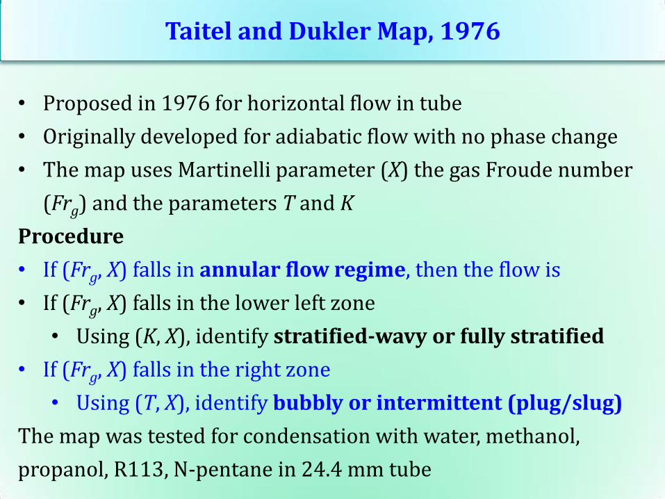
Taitel and Dukler Map, 1976
• Proposed in 1976 for horizontal flow in tube
• Originally developed for adiabatic flow with no phase change
• The map uses Martinelli parameter (Xtt) the gas Froude number
(FrG) and the parameters T and K
Procedure
Taitel and Dukler Map, 1976
• Proposed in 1976 for horizontal flow in tube
• Originally developed for adiabatic flow with no phase change
• The map uses Martinelli parameter (X) the gas Froude number
(Frg) and the parameters T and K
Procedure
• If (Frg, X) falls in annular flow regime, then the flow is
• If (Frg, X) falls in the lower left zone
• Using (K, X), identify stratified-wavy or fully stratified
• If (Frg, X) falls in the right zone
• Using (T, X), identify bubbly or intermittent (plug/slug)
The map was tested for condensation with water, methanol,
propanol, R113, N-pentane in 24.4 mm tube
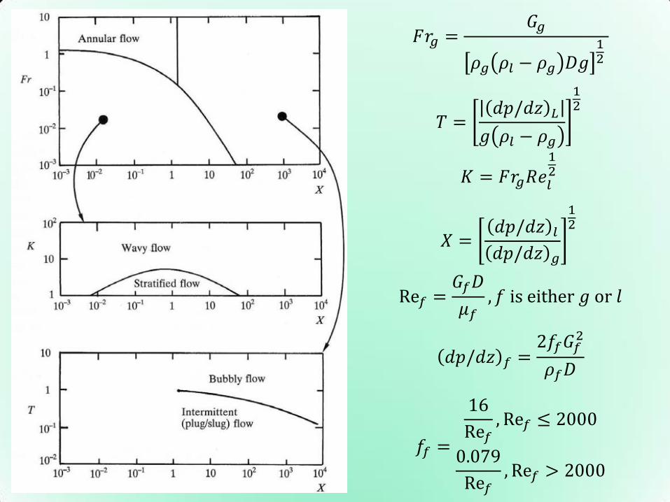
𝐹𝑟𝑔 =𝐺𝑔
𝜌𝑔 𝜌𝑙 − 𝜌𝑔 𝐷𝑔12
𝑇 =𝑑𝑝/𝑑𝑧 𝐿
𝑔 𝜌𝑙 − 𝜌𝑔
12
𝐾 = 𝐹𝑟𝑔𝑅𝑒𝑙
12
𝑋 =𝑑𝑝/𝑑𝑧 𝑙
𝑑𝑝/𝑑𝑧 𝑔
12
Re𝑓 =𝐺𝑓𝐷
𝜇𝑓, 𝑓 is either 𝑔 or 𝑙
𝑑𝑝/𝑑𝑧 𝑓 =2𝑓𝑓𝐺𝑓
2
𝜌𝑓𝐷
𝑓𝑓 =
16
Re𝑓, Re𝑓 ≤ 2000
0.079
Re𝑓, Re𝑓 > 2000
Problem: Flow Pattern in Vertical and Horizontal
Find the flow pattern when 4 kg/s of steam-water mixture of
quality 20% at 20 bar flows in a 0.1 m circular tube.
ρl = 850 kg/m3, ρg = 10 kg/m3, μl = 128×10-6 Pa s, μg = 16×10-6 Pa s
Problem: Flow Pattern in Vertical and Horizontal
Find the flow pattern when 4 kg/s of steam-water mixture of
quality 20% at 20 bar flows in a 0.1 m circular tube.
ρl = 850 kg/m3, ρg = 10 kg/m3, μl = 128×10-6 Pa s, μg = 16×10-6 Pa s
Quality, 𝑥 =𝐺𝑔
𝐺
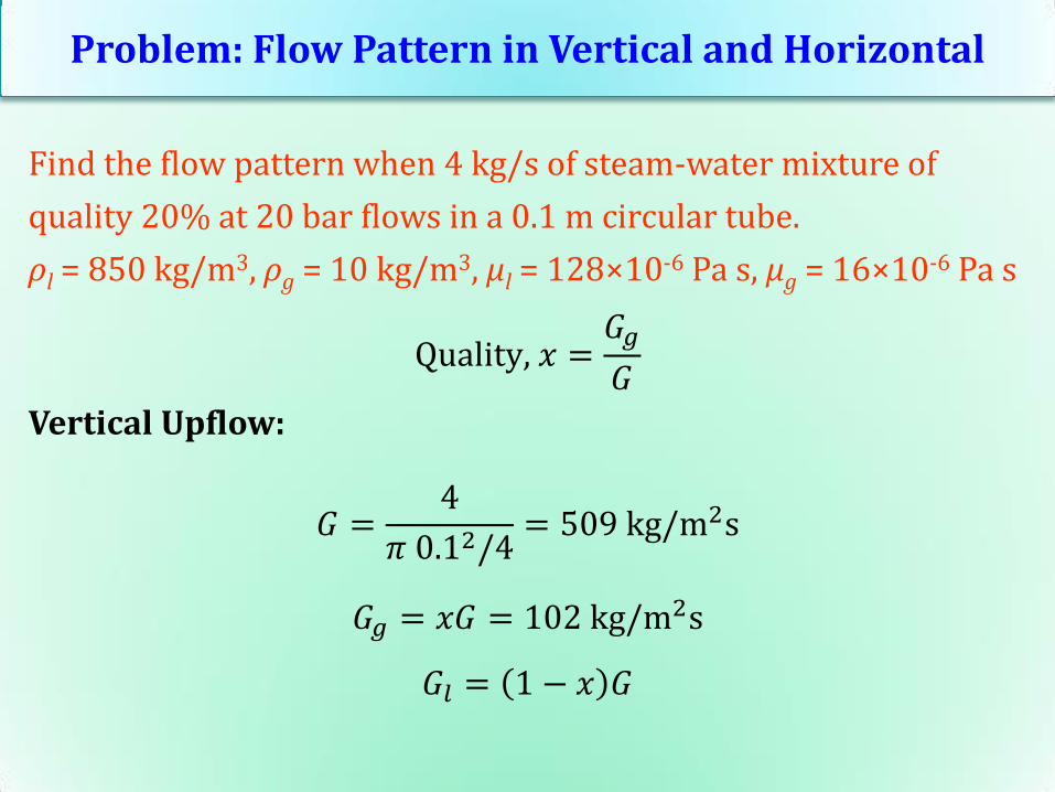
Problem: Flow Pattern in Vertical and Horizontal
Find the flow pattern when 4 kg/s of steam-water mixture of
quality 20% at 20 bar flows in a 0.1 m circular tube.
ρl = 850 kg/m3, ρg = 10 kg/m3, μl = 128×10-6 Pa s, μg = 16×10-6 Pa s
Quality, 𝑥 =𝐺𝑔
𝐺
Vertical Upflow:
𝐺 =4
𝜋 0.12/4= 509 kg/m2s
𝐺𝑔 = 𝑥𝐺 = 102 kg/m2s
𝐺𝑙 = 1 − 𝑥 𝐺

Problem: Flow Pattern in Vertical and Horizontal
Find the flow pattern when 4 kg/s of steam-water mixture of
quality 20% at 20 bar flows in a 0.1 m circular tube.
ρl = 850 kg/m3, ρg = 10 kg/m3, μl = 128×10-6 Pa s, μg = 16×10-6 Pa s
Quality, 𝑥 =𝐺𝑔
𝐺
Horizontal flow:
𝐺 =4
𝜋 0.12/4= 509 kg/m2s
𝐺𝑔 = 𝑥𝐺 = 102 kg/m2s
𝐺𝑙 = 1 − 𝑥 𝐺