Multimedia Hardware. 2 Overview Printer technology Scanning and digital cameras Display devices...
39
Multimedia Hardware
-
Upload
constance-griffith -
Category
Documents
-
view
215 -
download
2
Transcript of Multimedia Hardware. 2 Overview Printer technology Scanning and digital cameras Display devices...
Multimedia Hardware
2
Overview
• Printer technology
• Scanning and digital cameras
• Display devices
• Other peripherals
Printer Technology
4
The Technologies
• Dot matrix• Inkjet• Solid ink• Laser• Colour laser• Thermal wax transfer• Dye sublimation
5
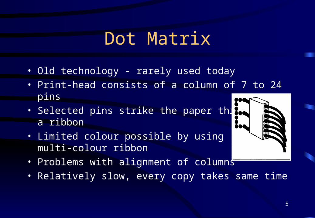
Dot Matrix
• Old technology - rarely used today• Print-head consists of a column of 7 to 24 pins• Selected pins strike the paper through
a ribbon• Limited colour possible by using
multi-colour ribbon• Problems with alignment of columns• Relatively slow, every copy takes same time
6
Inkjet
• Sprays a stream of CMYK ink through a set of fine nozzles mounted in a disposable cartridge.
• Heat sometimes applied to aid the ink’s drying.• Ink tends to bleed into ordinary paper.• Special paper often used - adds to the expense.• Resolutions of up to 1440dpi possible.• Capital cost low, running costs high.• Solid ink variations are now on the market.
7
Laser
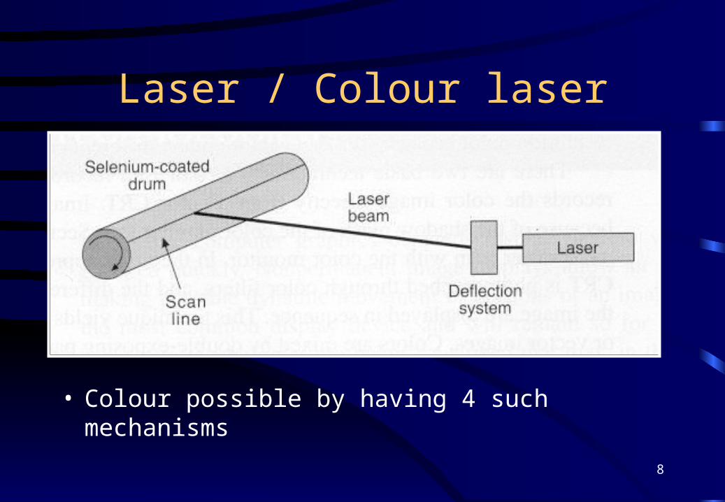
• Xerographic process• Charge transfer• Image on drum by laser• Toner• Heat to fix image• Resolutions up to 1200dpi possible• Higher capital cost, lower running cost
8
Laser / Colour laser
• Colour possible by having 4 such mechanisms
9
Thermal Wax Transfer
• Roll of plastic film coated with pigment-impregnated wax• Roll alternates page-sized panels of CMYK• Print head has thousands of heating elements which melt
the wax and transfer it to the paper• Glossy appearance to prints & vivid colours• Excellent results for OHP transparencies• Fixed running cost per sheet
10
Dye Sublimation
• Similar to thermal wax transfer - CMYK roll• Differs in method of colour transfer to paper
– inks are opaque and make a solid dot– dyes are transparent and merely tint the print media– (varied) heat changes the solid dye directly into a gas– immediate absorption by the polyester coating of the
print medium, producing a small coloured dot– dyes can mix, so no dithering is required– photographic quality results
Scanning & Digital Cameras
12
Sampling
• Like sound, scanning and digital cameras are further areas where an analogue signal is being sampled.
• How does the Nyquist Sampling Theory apply?– for frequency read resolution– typically, some detail is lost => what is acceptable?– for example, to record detail of 0.1mm, sample at
0.05mm (look at dpi details on scanner)
13
Scanners
• Detects light bounced back from document, at given colour depth and sample resolution
• Document type => colour depth / resolution– text bi-level, i.e. black & white– b&w drawing 256 grey levels, higher resolution– b&w photo 256 grey levels, lower resolution– colour drawing 256 colours, higher resolution– colour photo 256 colours, lower resolution– full colour photo 16.7M colours, lower resolution
14
Beware the file size!
A4 page scanned as colour photographpage size is approximately 81/3” x 112/3”
typical resolution is 150dpi (dots per inch)
81/3 x 150 x 112/3 x 150 = 2,187,500dots
colour depth typically 256 colours => 1 byte per dot
so, final file size is 2,187,500 / (1024 x 1024) = 2.1MB
15
Consider the output path
• Screen resolution is typically 75-72dpi• Inkjet printers are typically 360-720dpi• Laser printers are typically 300-600dpi
BUT…• beware of dithering which reduces effective
resolution
16
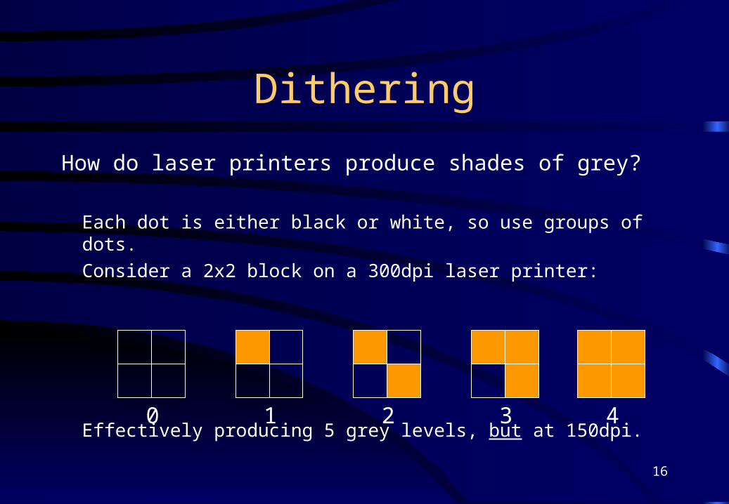
Dithering
How do laser printers produce shades of grey?
Each dot is either black or white, so use groups of dots.
Consider a 2x2 block on a 300dpi laser printer:
Effectively producing 5 grey levels, but at 150dpi.0 1 2 3 4
17
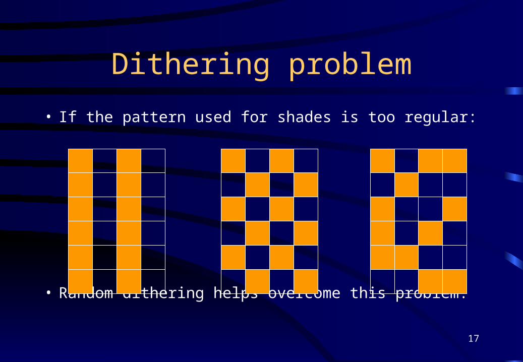
• If the pattern used for shades is too regular:
• Random dithering helps overcome this problem.
Dithering problem
18
Digital Cameras
• Television cameras generally use the vidicon image-sensing tube– similar to a CRT in construction– light at the faceplate causes electrons to flow thru– this is detected and generates the video signal
• Solid-state sensor arrays are now taking over– CCD (the charge-coupled device)
19
CCD
• Single chip manufactured on light-sensitive crystalline silicon
• A rectangular array of photo-detector sites• Light falling on a site causes loss of charge• When the site is ‘inspected’, the current needed
to re-charge it is proportional to the amount of light which has fallen on it - i.e. a grey level.
Display Devices et al
21
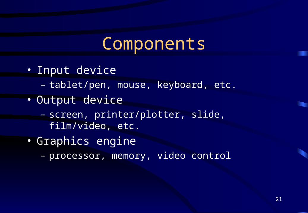
Components• Input device
– tablet/pen, mouse, keyboard, etc.
• Output device– screen, printer/plotter, slide, film/video, etc.
• Graphics engine– processor, memory, video control
22
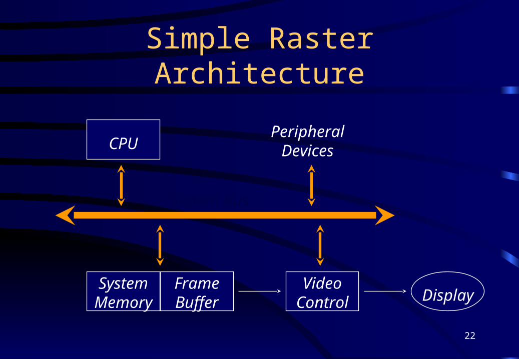
Simple Raster Architecture
CPU
SystemMemory
FrameBuffer
VideoControl Display
System Bus
PeripheralDevices
23
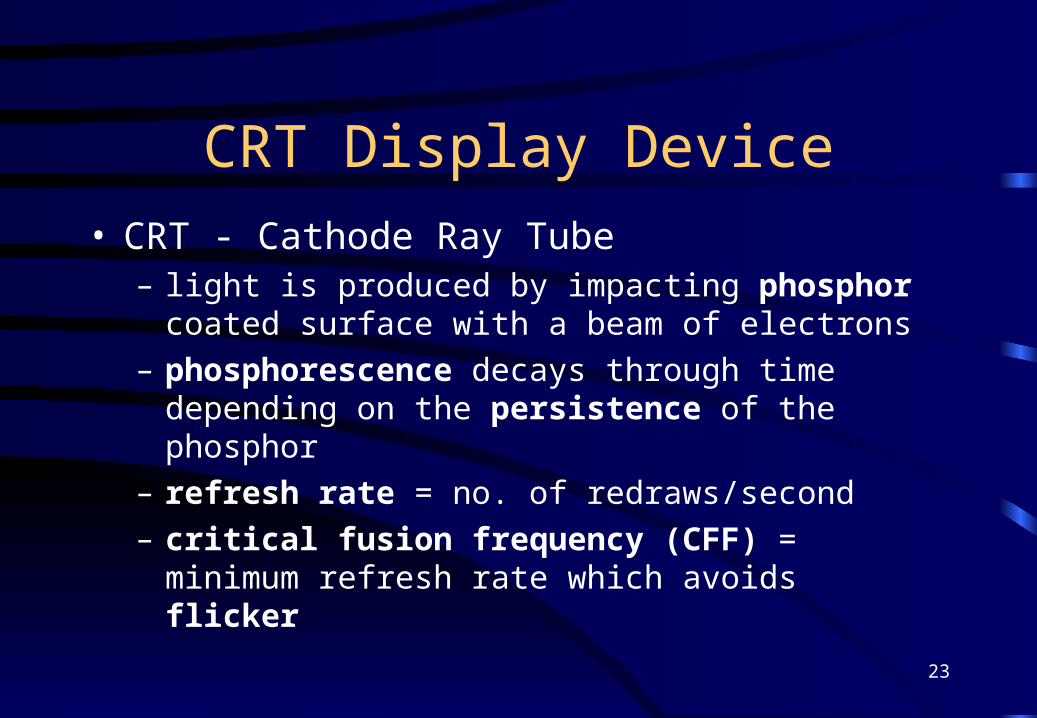
CRT Display Device• CRT - Cathode Ray Tube
– light is produced by impacting phosphor coated surface with a beam of electrons
– phosphorescence decays through time depending on the persistence of the phosphor
– refresh rate = no. of redraws/second– critical fusion frequency (CFF) = minimum refresh
rate which avoids flicker

24
Monochrome CRT Schematic
Evacuated tube
Electron gun
Focus mechanism
Horizontal & verticaldeflection plates
Phosphor coatedsurface
Electron beam
Phosphorescence
25
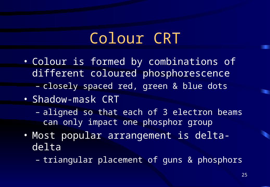
Colour CRT• Colour is formed by combinations of different
coloured phosphorescence– closely spaced red, green & blue dots
• Shadow-mask CRT– aligned so that each of 3 electron beams can only
impact one phosphor group
• Most popular arrangement is delta-delta– triangular placement of guns & phosphors
26
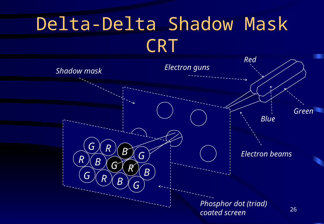
Delta-Delta Shadow Mask CRT
R B
G RR
RB
B
B
G
GG
Electron gunsShadow mask
Phosphor dot (triad)coated screen
Green
Red
Blue
Electron beamsG
27
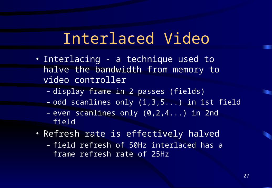
Interlaced Video• Interlacing - a technique used to halve the
bandwidth from memory to video controller– display frame in 2 passes (fields)– odd scanlines only (1,3,5...) in 1st field– even scanlines only (0,2,4...) in 2nd field
• Refresh rate is effectively halved– field refresh of 50Hz interlaced has a frame
refresh rate of 25Hz
28
Video Cards
• Issues to consider in specifying a video card– resolutions supported )– colour depth )- related– interlacing / non-interlacing)– size & type of the on-board memory, e.g. 8MB SGRAM
(static graphics RAM)– double-buffering– hardware acceleration, e.g. 3D-AGP– bus interface, e.g. PCI
29
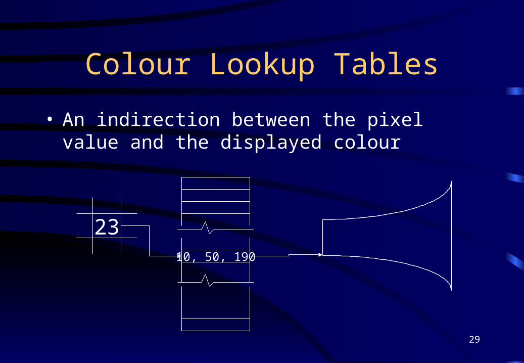
Colour Lookup Tables
• An indirection between the pixel value and the displayed colour
2310, 50, 190
30
Palette
• n-bit pixel => 2n simultaneous colour palette– also means 2n entries in the CLUT
• CLUT permits wider choice of colours for this palette depending on the number of output bits– n output bits also implies 2n potential colours
• Example: 8-bit pixel & 24-bit output– 256 simultaneous colours drawn from 16.7 million
31
Output bits
The combination of output bits has important
implications; examples:24-bits, 8 for each of RGB => max of 256 grey levels
8-bits, 3 for R, 3 for G, 2 for B => max of 4 grey levelsalso non-linear 256 colour scale (more yellows)
9-bits, 3 for each of RGB => max of 8 grey levelsbut now a linear scale of 512 colours
Sections of the CLUT are sometimes reserved.

Other Peripherals
33
DVD
• Digital Versatile Disk– high capacity replacement for CD-ROM– capacity of 5 GB per side– equates to ~130 minutes of MPEG-2 video + sound– high quality video (slightly better than S-VHS)– Dolby Digital 5.1 soundtrack (also surround sound)– multiple soundtracks possible (e.g. languages)– movies often region coded, e.g. 1=USA, 2=Europe
• New Formats– HD DVD, capacity 15GB per side– Blu Ray, capacity 25GB per side
34
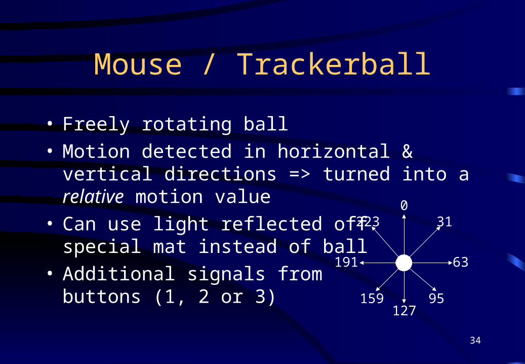
Mouse / Trackerball
• Freely rotating ball• Motion detected in horizontal & vertical directions
=> turned into a relative motion value• Can use light reflected off
special mat instead of ball• Additional signals from
buttons (1, 2 or 3)
031
63
95127
159
191
223
35
Digitising Tablet
• Flat bed of a fine grid of horizontal and vertical wires
• User has a puck, often with cross-hairs & buttons• Puck has a coil of wire which sets up a field• Field induces a current in horizontal/vertical wires,
depending on actual position (x,y) co-ord.• Accuracy down to .001” - height possible also
36
Light Pens
• The apparent ability to draw on the screen• Pen detects the CRT beam as it passes by• Timing determines the pen’s position on screen• Software does the drawing / selecting etc.• Pen can be radio-linked for cordless operation
• Alternative: use a stylus and touch sensitivity...
37
Touch Sensitive Screens
• Two main systems:– two membranes with slight separation, pushed together by the
finger and/or stylus• hard to get fine resolution unless using a stylus
• prone to physical damage, wear, dirt
– grid of light beams criss-cross the screen, finger breaks the beams vertically and horizontally
• more robust
• screen tends to get dirty from use
• Tablet PCs– Hand writing recognition
38
Voice Input & Output
• Voice input coming of age• Low cost systems now in common use
– ViaVoice, SpeakEasy, etc.
• Strong need to train systems for several hours• Training unnecessary for limited applications• Voice output less of a problem
– similar idea to wave tables / samples
39
The Future
• Voice driven input– is it always appropriate?
• Gesture recognition– necessary for greater recognition accuracy?
• Larger output displays– desktop sized?
• Faster communications connections– software on a vendor server; licence to use for time