Multi-Point Inline Extensometer Installation Manual · movement behavior of soil, rock, and...
27
EXM0097I All efforts have been made to ensure the accuracy and completeness of the information contained in this document. RST Instruments Ltd reserves the right to change the information at any time and assumes no liability for its accuracy. Copyright © 2019. RST Instruments Ltd. All rights reserved. Document Number: EXM0097I Release Date: September 16, 2019 Multi-Point Inline Extensometer Installation Manual
Transcript of Multi-Point Inline Extensometer Installation Manual · movement behavior of soil, rock, and...

EXM0097I
All efforts have been made to ensure the accuracy and completeness of the information contained in this document. RST Instruments Ltd reserves the right to change the information at any time and assumes no liability for its accuracy. Copyright © 2019. RST Instruments Ltd. All rights reserved.
Document Number: EXM0097I
Release Date: September 16, 2019
Multi-Point Inline Extensometer Installation
Manual

Multi-Point Inline Extensometer Installation Manual
EXM0097I RST Instruments Ltd. i
REVISION HISTORY
Rev. Revision History Date Prepared By Approved By
A Initial Release. 2013-Feb-20
B Updated images, materials, instructions. 2014-Sep-16
C Updated description, tools, warnings, instructions.
2014-Oct-02
D Minor updates. 2014-Oct-02
E New pictures, updated formatting. 2015-Oct-05
F Content editing. 2015-Oct-06
G Updated formatting, pictures, spider anchors added.
2018-Jan-15
H Instructions about safety cable, tremie pipes and trigger pin release added.
2019-Feb-04 MP TW
I Operation and Temperature Correction section added
2019-Sep-16 MP QR

Multi-Point Inline Extensometer Installation Manual
EXM0097I RST Instruments Ltd. ii
TABLE OF CONTENTS
1 INTRODUCTION ............................................................................................................ 1
1.1 Components ..................................................................................................... 1
2 SAFETY ...................................................................................................................... 3
3 TOOLS AND COMPONENTS ........................................................................................... 3
3.1 Installation Tools ............................................................................................... 3
3.2 Components for Inline Extensometer Assembly with Groutable Anchors .......... 4
3.3 Components for Inline Extensometer Assembly with Groutable Spider Anchors ......................................................................................................................... 4
4 INSTALLATION PROCEDURE ......................................................................................... 6
4.1 Important Considerations .................................................................................. 6
4.2 Downhole Installation ........................................................................................ 6
4.3 Preparation ....................................................................................................... 7
4.4 General Assembly ........................................................................................... 11
4.5 Final Steps ...................................................................................................... 19
4.5.1 Optional Temporary Surface Anchor ..................................................... 19
4.5.2 Groutable Anchor .................................................................................. 20
4.5.3 Groutable Spider Anchor ....................................................................... 20
4.6 Horizontal and Up-Hole Installations ............................................................... 20
5 CONNECTING TO A READOUT OR DATA LOGGER ......................................................... 21
6 OPERATION .............................................................................................................. 21
6.1 Temperature Correction .................................................................................. 21
7 SERVICE AND REPAIR ................................................................................................ 23

Multi-Point Inline Extensometer Installation Manual
EXM0097I RST Instruments Ltd. iii
LIST OF FIGURES
Figure 1-1 Multi-point inline extensometer with groutable anchors ............................................. 2
Figure 3-1 Groutable anchor ...................................................................................................... 4
Figure 3-2 Groutable spider anchor ............................................................................................ 5
Figure 3-3 Groutable spider anchor, bottom view ....................................................................... 5
Figure 3-4 Trigger pin in place ................................................................................................... 6
Figure 4-1 Telescopic set line .................................................................................................... 8
Figure 4-2 Sections layout.......................................................................................................... 9
Figure 4-3 Multi-point inline extensometer with groutable spider anchor .................................. 10
Figure 4-4 Attaching the bottom groutable anchor to the extensometer rod ............................. 11
Figure 4-5 Extensometer rod connection to groutable anchor .................................................. 12
Figure 4-6 PVC sheath connection to groutable anchor ........................................................... 12
Figure 4-7 Safety cable attached to the bottom groutable spider anchor .................................. 12
Figure 4-8 Anchor spring details............................................................................................... 14
Figure 4-9 Telescopic set line .................................................................................................. 15
Figure 4-10 Pushing the ½” PVC sheath into the telescopic coupling ....................................... 16
Figure 4-11 Swivel connection ................................................................................................. 16
Figure 4-12 Tightening the swivel nut ....................................................................................... 17
Figure 4-13 Center Rod Swivel Connection ............................................................................. 18
Figure 4-14 Extensometer head mounting bar ......................................................................... 19
LIST OF TABLES
Table 6-1 Temperature correction factor .................................................................................. 22
LIST OF EQUATIONS
Equation 1 Actual deformation ................................................................................................. 21
Equation 2 Linear displacement ............................................................................................... 21
Equation 3 Temperature correction factor ................................................................................ 22

Multi-Point Inline Extensometer Installation Manual
EXM0097I RST Instruments Ltd. 1
1 INTRODUCTION
Multi-point inline extensometers are used to determine the stability and relative movement behavior of soil, rock, and concrete structures. An inline extensometer with multiple anchor points can be used to determine relative movements between set anchor points within a single borehole.
Measurement sensors in multi-point inline extensometers are vibrating wire displacement transducers which provide extremely stable and accurate output which can be temperature corrected.
Typical applications of the multi-point inline extensometers include measurements of:
• Ground movements around tunnels.
• Deformations of dam abutments and foundations.
• Ground movement behind retaining walls, sheet piling, slurry walls, etc.
• Ground movements in the walls of open pit mines.
• Deformation of concrete piles (tell-tales).
• Deformation in the walls and roofs of underground openings.
• Subsidence above tunnels and mine openings.
• Settlement and heave of foundations due to loading.
1.1 COMPONENTS
Each inline extensometer assembly comes with the following components. Ensure all components are present prior to installation:
• Sensor assembly (anchors built in) – equal to the number of points to be monitored.
• Bottom anchor.
• Surface installation anchor bar (optional).
• Extension rods and sheathes –supplied in either imperial or metric unit lengths as required (typically 1m, 2m, 3m, 5ft or 10ft, but custom length can be provided to meet specific anchor location objectives).
• Sensor cable – sufficient length to run from each sensor to the borehole collar for connecting the sensors to the readout equipment or datalogger.
• Cable sheathing (for groutable borehole only) - sufficient length to run from each sensor to the borehole collar to prevent the grout from bonding to the cable.

Multi-Point Inline Extensometer Installation Manual
EXM0097I RST Instruments Ltd. 2
• Safety cable – 3/32” 7x7 braided stainless steel. Although optional, the use of the safety cable during installation is highly recommended.
FIGURE 1-1 MULTI-POINT INLINE EXTENSOMETER WITH GROUTABLE ANCHORS

Multi-Point Inline Extensometer Installation Manual
EXM0097I RST Instruments Ltd. Page 3
2 SAFETY
Normal safety precautions should be followed and proper personal protective equipment (PPE) should be worn when working in the field with this equipment, including safety glasses and gloves.
Grout, Loctite, PVC solvent and PVC cement may cause irritation if they come into direct contact with eyes and skin. It is important to wear PPE to prevent direct contact. Refer to the product’s MSDS for specific information and first aid procedures should contact occur.
3 TOOLS AND COMPONENTS
Multi-point inline extensometers are typically installed within a borehole using groutable or groutable spider anchors. Grout backfill provides a bond connection between the instrument end anchor points and the borehole walls. Typical installations will only have instrument cables exiting from the borehole collar which will be connected to a remote data logger or readout unit. Care must be taken to protect the instrument cables from damage.
3.1 INSTALLATION TOOLS
The following tools are required for installation of an inline extensometer assembly:
• Thread locker (Loctite #242).
• Hex Allen key set (imperial).
• PVC solvent.
• PVC cement.
• PVC electrical tape – ¾" rolls, multiple.
• Wrench set (imperial) – specifically ½" and 9/16" are required.
• Rigid tremie piping – ¾”.
• Philips screwdriver.
• Flathead screwdriver.
• Release lines for spider leg trigger pins (for spider leg anchors).
• Grout pump (for groutable anchors).
• Grout (appropriate for the type of soil) (for groutable anchors).
• VW Readout (VW2106) or FlexDaq datalogger.
Multi-Point Inline Extensometer Installation Manual
EXM0097I RST Instruments Ltd. Page 4
3.2 COMPONENTS FOR INLINE EXTENSOMETER ASSEMBLY WITH
GROUTABLE ANCHORS
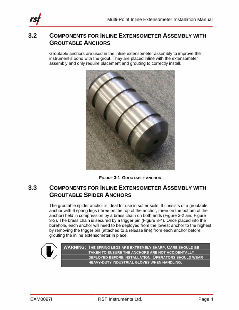
Groutable anchors are used in the inline extensometer assembly to improve the instrument’s bond with the grout. They are placed inline with the extensometer assembly and only require placement and grouting to correctly install.
FIGURE 3-1 GROUTABLE ANCHOR
3.3 COMPONENTS FOR INLINE EXTENSOMETER ASSEMBLY WITH
GROUTABLE SPIDER ANCHORS
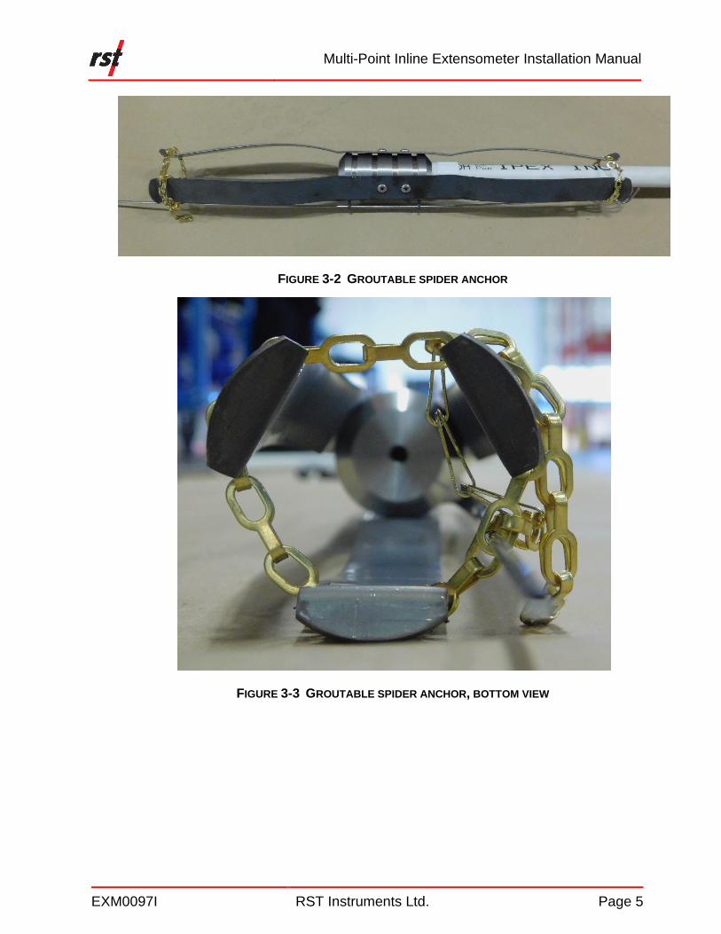
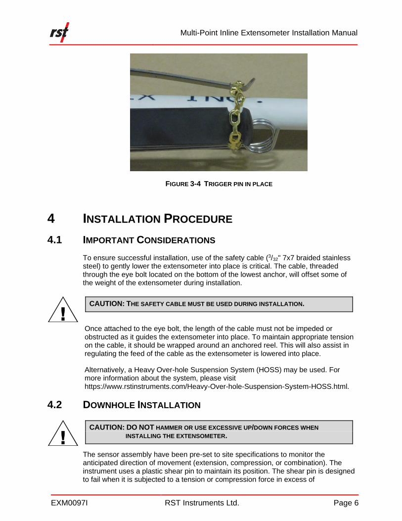
The groutable spider anchor is ideal for use in softer soils. It consists of a groutable anchor with 6 spring legs (three on the top of the anchor, three on the bottom of the anchor) held in compression by a brass chain on both ends (Figure 3-2 and Figure 3-3). The brass chain is secured by a trigger pin (Figure 3-4). Once placed into the borehole, each anchor will need to be deployed from the lowest anchor to the highest by removing the trigger pin (attached to a release line) from each anchor before grouting the inline extensometer in place.
WARNING: THE SPRING LEGS ARE EXTREMELY SHARP. CARE SHOULD BE
TAKEN TO ENSURE THE ANCHORS ARE NOT ACCIDENTALLY
DEPLOYED BEFORE INSTALLATION. OPERATORS SHOULD WEAR
HEAVY-DUTY INDUSTRIAL GLOVES WHEN HANDLING.
Multi-Point Inline Extensometer Installation Manual
EXM0097I RST Instruments Ltd. Page 5
FIGURE 3-2 GROUTABLE SPIDER ANCHOR
FIGURE 3-3 GROUTABLE SPIDER ANCHOR, BOTTOM VIEW
Multi-Point Inline Extensometer Installation Manual
EXM0097I RST Instruments Ltd. Page 6
FIGURE 3-4 TRIGGER PIN IN PLACE
4 INSTALLATION PROCEDURE
4.1 IMPORTANT CONSIDERATIONS
To ensure successful installation, use of the safety cable (3/32" 7x7 braided stainless steel) to gently lower the extensometer into place is critical. The cable, threaded through the eye bolt located on the bottom of the lowest anchor, will offset some of the weight of the extensometer during installation.
CAUTION: THE SAFETY CABLE MUST BE USED DURING INSTALLATION.
Once attached to the eye bolt, the length of the cable must not be impeded or obstructed as it guides the extensometer into place. To maintain appropriate tension on the cable, it should be wrapped around an anchored reel. This will also assist in regulating the feed of the cable as the extensometer is lowered into place.
Alternatively, a Heavy Over-hole Suspension System (HOSS) may be used. For more information about the system, please visit https://www.rstinstruments.com/Heavy-Over-hole-Suspension-System-HOSS.html.
4.2 DOWNHOLE INSTALLATION
CAUTION: DO NOT HAMMER OR USE EXCESSIVE UP/DOWN FORCES WHEN
INSTALLING THE EXTENSOMETER.
The sensor assembly have been pre-set to site specifications to monitor the anticipated direction of movement (extension, compression, or combination). The instrument uses a plastic shear pin to maintain its position. The shear pin is designed to fail when it is subjected to a tension or compression force in excess of

Multi-Point Inline Extensometer Installation Manual
EXM0097I RST Instruments Ltd. Page 7
approximately 200 lbs (91 kg). It is therefore very important to not exceed this force when installing the instrumentation and to use the safety cable to off set the weight of the instrument during installation.
CAUTION: DO NOT EXCEED 200 LB OF FORCE WHEN INSTALLING THE
EXTENSOMETER.
4.3 PREPARATION
1 Drill the borehole to the desired depth, which should be a minimum of approximately 3 feet (1 meter deeper) than the bottom anchor depth. The width of the borehole will depend on the type of anchor used.
2 The depth, of the borehole, should be confirmed by bottom sounding immediately prior to installing the instrumentation, to ensure that a blockage has not occurred and that the full depth of the borehole is available for use.
3 Prepare an installation design plan which will confirm the required instrument components and their target depths. This design plan will indicate:
• the location and position of each sensor anchor;
• the number of extensions (standard imperial, metric or custom lengths) required for the planned installation.
4 Layout all of the required installation components, side by side, in the order that they will be installed into the borehole, from the bottom of the borehole to the top.
5 Number all components sequentially, starting with “1” for the bottom anchor, with a felt tip marker. Ensure that number is visible on both the top and bottom ends of each component. Double check everything against the installation design plan to ensure all components and locations are correct.
6 If there is no set line on the telescopic extension sheath on the extension kit, one will need to be drawn on prior to installation to avoid over extension or compression. Use the following method to draw a set line on the extension sheath:
A Remove the telescopic extension sheath from the extension sheath coupling.
B Using a felt-tipped marker, draw the set line 8 ⅛” (206mm) from the end of the extension sheath that goes into the extension sheath coupling.
NOTE: IF EXCESSIVE WALL CAVING IS ANTICIPATED, THE BOREHOLE MAY NEED TO BE
EXTENDED.

Multi-Point Inline Extensometer Installation Manual
EXM0097I RST Instruments Ltd. Page 8
FIGURE 4-1 TELESCOPIC SET LINE
C Insert the telescopic extension sheath back into the extension sheath coupling to the set line.
D Use electrical tape to secure the telescopic extension sheath and coupling into place and prevent it from moving during the rest of the installation process.
7 Carefully verify all of the components required for the installation are present and note all serial numbers and tag numbers on the installation design plan. Refer to Figures 3-1 and 3-2.
8 Check each VW sensor to ensure that no damage occurred during shipping. Make sure that the shear pin is holding and in place (i.e. it should not be possible to pull the shaft on the sensor out or push it farther in). Use the VW readout to confirm that the readings prior to installation are consistent with the supplied calibration sheets.

Multi-Point Inline Extensometer Installation Manual
EXM0097I RST Instruments Ltd. Page 9
FIGURE 4-2 SECTIONS LAYOUT

Multi-Point Inline Extensometer Installation Manual
EXM0097I RST Instruments Ltd. Page 10
FIGURE 4-3 MULTI-POINT INLINE EXTENSOMETER WITH GROUTABLE SPIDER ANCHOR
Multi-Point Inline Extensometer Installation Manual
EXM0097I RST Instruments Ltd. Page 11
4.4 GENERAL ASSEMBLY
The following section outlines the steps necessary for a successful assembly and installation of a multi-point inline extensometer assembly.
CAUTION: DO NOT ROTATE THE EXTENSOMETER ROD DURING INSTALLATION. ONLY THE EXTENSION RODS NOT CONNECTED TO THE SENSOR ABOVE
CAN BE ROTATED WHEN CARRYING OUT THE INSTALLATION
PROCEDURE. EXCESSIVE ROTATION, IN EITHER CLOCKWISE OR
COUNTER-CLOCKWISE DIRECTIONS WILL DAMAGE THE VW
DISPLACEMENT SENSORS.
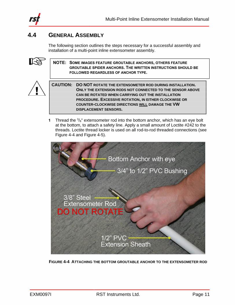
1 Thread the 3/8" extensometer rod into the bottom anchor, which has an eye bolt at the bottom, to attach a safety line. Apply a small amount of Loctite #242 to the threads. Loctite thread locker is used on all rod-to-rod threaded connections (see Figure 4-4 and Figure 4-5).
FIGURE 4-4 ATTACHING THE BOTTOM GROUTABLE ANCHOR TO THE EXTENSOMETER ROD
NOTE: SOME IMAGES FEATURE GROUTABLE ANCHORS, OTHERS FEATURE
GROUTABLE SPIDER ANCHORS. THE WRITTEN INSTRUCTIONS SHOULD BE
FOLLOWED REGARDLESS OF ANCHOR TYPE.

Multi-Point Inline Extensometer Installation Manual
EXM0097I RST Instruments Ltd. Page 12
FIGURE 4-5 EXTENSOMETER ROD CONNECTION TO GROUTABLE ANCHOR
2 Slide the ½" PVC sheath over the 3/8" extensometer rod installed in the previous step and glue into the reducer bushing at the top the bottom anchor (Figure 4-6).
FIGURE 4-6 PVC SHEATH CONNECTION TO GROUTABLE ANCHOR
3 Attach a safety cable to the eye bolt on bottom anchor using the quick link on the end of the cable (Figure 4-7).
FIGURE 4-7 SAFETY CABLE ATTACHED TO THE BOTTOM GROUTABLE SPIDER ANCHOR

Multi-Point Inline Extensometer Installation Manual
EXM0097I RST Instruments Ltd. Page 13
4 If the stainless-steel safety cable is to be abandoned in the hole, it can be clamped directly onto the eye. If the cable is to be recovered prior to grouting, feed the cable through the eyebolt and secure at the top of the borehole. Feed the other end of the cable into the borehole, making a continuous loop, when lowering the extensometer assembly into the borehole. When the line is no longer required for lowering the instrument, it can be released on one side and pulled back to the surface.
5 If spider anchors are used in the assembly,
a Attach a trigger release line to the trigger pin on each anchor, leaving enough slack in the line for it to exit the borehole without any tension on the line (Figure 4-8). Each trigger release line should be numbered for easy identification after the extensometer is installed.
b Maintain some slack in the release line(s) while lowering the extensometer system into the borehole to prevent premature release of the anchor spring legs. Make sure the free end of the release line is secured to prevent it from falling into the borehole.
NOTE: ALTERNATIVELY, DIFFERENT COLOURED LINES MAY BE USED TO FACILITATE
IDENTIFICATION.
NOTE: A HOSS OR REEL WILL BE VERY USEFUL IN MAINTAINING TENSION IN THE
SAFETY CABLE.

Multi-Point Inline Extensometer Installation Manual
EXM0097I RST Instruments Ltd. Page 14
FIGURE 4-8 ANCHOR SPRING DETAILS
6 Attach the tremie pipe or grout line to the bottom anchor.
CAUTION: THE TREMIE PIPE WILL RUN THE LENGTH OF THE EXTENSOMETER
ASSEMBLY. ENSURE THAT THE PIPE IS TAPED TO THE ASSEMBLY EVERY
FEW METERS AND, IF USING GROUTABLE SPIDER ANCHORS, DOES NOT
INTERFERE WITH THE RELEASE OF THE SPRING LEGS.
NOTE: THE TREMIE PIPE MAY ALSO BE USED TO HELP OFFSET THE WEIGHT OF THE
EXTENSOMETER ASSEMBLY.
Multi-Point Inline Extensometer Installation Manual
EXM0097I RST Instruments Ltd. Page 15
7 Lower the bottom anchor into the borehole and hold it in place until the next section is ready to be installed.
CAUTION: KEEP TENSION ON THE SAFETY CABLE THROUGH THE ENTIRE
INSTALLATION TO PREVENT THE WEIGHT OF THE EXTENSOMETER
ASSEMBLY DAMAGING THE SENSORS.
8 Slide a PVC sheath extension over the next length of 3/8" extension rod, with the telescopic coupling opposite to the threaded end of the rod. Thread the 3/8" extension rod onto the previously installed extensometer rod, holding back the PVC sheath extension.
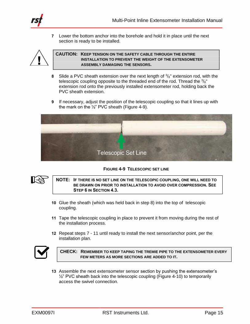
9 If necessary, adjust the position of the telescopic coupling so that it lines up with the mark on the ½” PVC sheath (Figure 4-9).
FIGURE 4-9 TELESCOPIC SET LINE
10 Glue the sheath (which was held back in step 8) into the top of telescopic coupling.
11 Tape the telescopic coupling in place to prevent it from moving during the rest of the installation process.
12 Repeat steps 7 - 11 until ready to install the next sensor/anchor point, per the installation plan.
13 Assemble the next extensometer sensor section by pushing the extensometer’s ½” PVC sheath back into the telescopic coupling (Figure 4-10) to temporarily access the swivel connection.
NOTE: IF THERE IS NO SET LINE ON THE TELESCOPIC COUPLING, ONE WILL NEED TO
BE DRAWN ON PRIOR TO INSTALLATION TO AVOID OVER COMPRESSION. SEE
STEP 6 IN SECTION 4.3.
CHECK: REMEMBER TO KEEP TAPING THE TREMIE PIPE TO THE EXTENSOMETER EVERY
FEW METERS AS MORE SECTIONS ARE ADDED TO IT.
Multi-Point Inline Extensometer Installation Manual
EXM0097I RST Instruments Ltd. Page 16
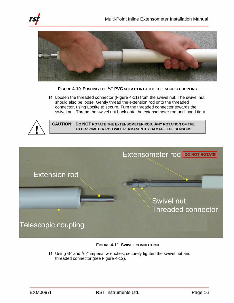
FIGURE 4-10 PUSHING THE ½” PVC SHEATH INTO THE TELESCOPIC COUPLING
14 Loosen the threaded connector (Figure 4-11) from the swivel nut. The swivel nut should also be loose. Gently thread the extension rod onto the threaded connector, using Loctite to secure. Turn the threaded connector towards the swivel nut. Thread the swivel nut back onto the extensometer rod until hand tight.
CAUTION: DO NOT ROTATE THE EXTENSOMETER ROD. ANY ROTATION OF THE
EXTENSOMETER ROD WILL PERMANENTLY DAMAGE THE SENSORS.
FIGURE 4-11 SWIVEL CONNECTION
15 Using ½" and 9/16" imperial wrenches, securely tighten the swivel nut and threaded connector (see Figure 4-12).

Multi-Point Inline Extensometer Installation Manual
EXM0097I RST Instruments Ltd. Page 17
FIGURE 4-12 TIGHTENING THE SWIVEL NUT
CAUTION: TAKE CARE AND DO NOT ROTATE THE EXTENSOMETER ROD. ANY
ROTATION OF THE EXTENSOMETER ROD WILL PERMANENTLY DAMAGE
THE SENSORS.
16 Gently pull down on the ½" PVC sheath from the extensometer and glue it into the telescopic coupling’s bushing at the top of extension’s telescopic coupler using PVC solvent cement.
Multi-Point Inline Extensometer Installation Manual
EXM0097I RST Instruments Ltd. Page 18
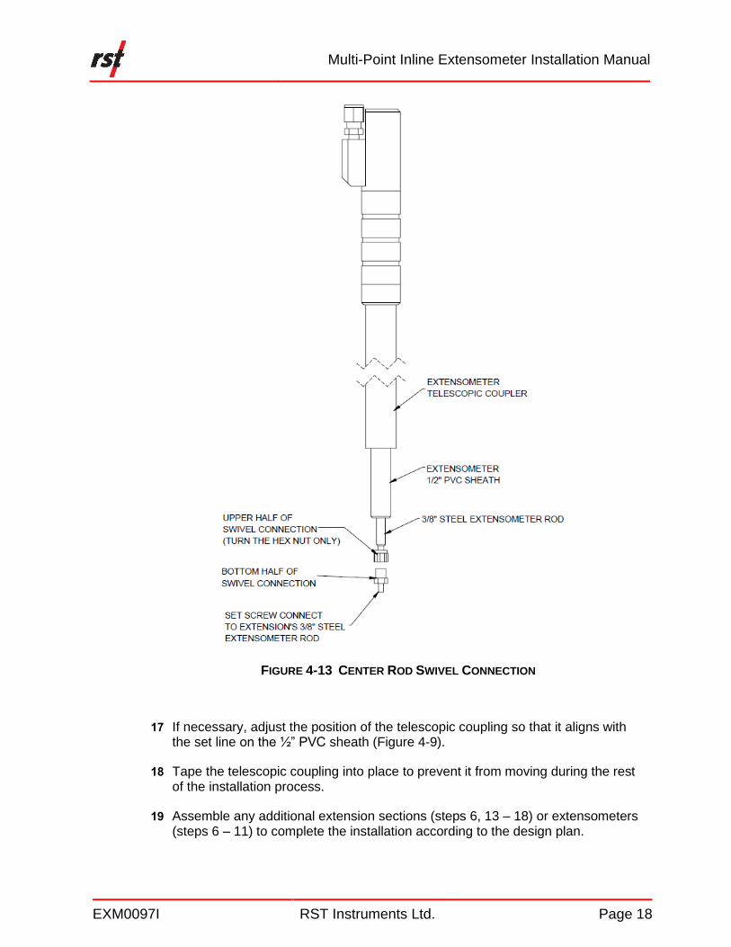
FIGURE 4-13 CENTER ROD SWIVEL CONNECTION
17 If necessary, adjust the position of the telescopic coupling so that it aligns with the set line on the ½” PVC sheath (Figure 4-9).
18 Tape the telescopic coupling into place to prevent it from moving during the rest of the installation process.
19 Assemble any additional extension sections (steps 6, 13 – 18) or extensometers (steps 6 – 11) to complete the installation according to the design plan.
Multi-Point Inline Extensometer Installation Manual
EXM0097I RST Instruments Ltd. Page 19
CAUTION: DO NOT ROTATE THE RODS IN RELATION TO THE SENSOR DURING
INSTALLATION.
CAUTION: ONCE ALL SECTIONS OF THE EXTENSOMETER HAVE BEEN ADDED AND THE
ASSEMBLY IS IN THE BOREHOLE, CONTINUE TO HOLD THE EXTENSOMETER
IN PLACE UNTIL THE GROUT HAS BEEN ADDED.
4.5 FINAL STEPS
The steps to complete the installation of an inline extensometer depends on the types of anchors used. The following sections detail the final steps for both groutable anchors and groutable spider anchors.
4.5.1 Optional Temporary Surface Anchor
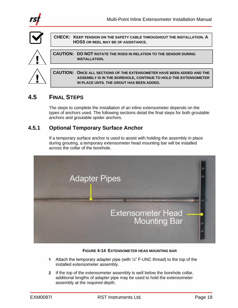
If a temporary surface anchor is used to assist with holding the assembly in place during grouting, a temporary extensometer head mounting bar will be installed across the collar of the borehole.
FIGURE 4-14 EXTENSOMETER HEAD MOUNTING BAR
1 Attach the temporary adapter pipe (with ¼” F-UNC thread) to the top of the installed extensometer assembly.
2 If the top of the extensometer assembly is well below the borehole collar, additional lengths of adapter pipe may be used to hold the extensometer assembly at the required depth.
CHECK: KEEP TENSION ON THE SAFETY CABLE THROUGHOUT THE INSTALLATION. A
HOSS OR REEL MAY BE OF ASSISTANCE.
Multi-Point Inline Extensometer Installation Manual
EXM0097I RST Instruments Ltd. Page 20
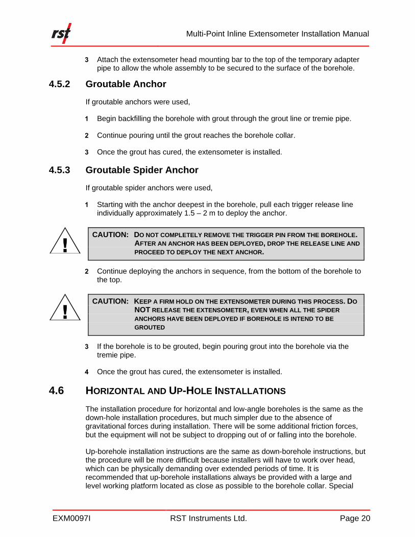
3 Attach the extensometer head mounting bar to the top of the temporary adapter pipe to allow the whole assembly to be secured to the surface of the borehole.
4.5.2 Groutable Anchor
If groutable anchors were used,
1 Begin backfilling the borehole with grout through the grout line or tremie pipe.
2 Continue pouring until the grout reaches the borehole collar.
3 Once the grout has cured, the extensometer is installed.
4.5.3 Groutable Spider Anchor
If groutable spider anchors were used,
1 Starting with the anchor deepest in the borehole, pull each trigger release line individually approximately 1.5 – 2 m to deploy the anchor.
CAUTION: DO NOT COMPLETELY REMOVE THE TRIGGER PIN FROM THE BOREHOLE. AFTER AN ANCHOR HAS BEEN DEPLOYED, DROP THE RELEASE LINE AND
PROCEED TO DEPLOY THE NEXT ANCHOR.
2 Continue deploying the anchors in sequence, from the bottom of the borehole to the top.
CAUTION: KEEP A FIRM HOLD ON THE EXTENSOMETER DURING THIS PROCESS. DO
NOT RELEASE THE EXTENSOMETER, EVEN WHEN ALL THE SPIDER
ANCHORS HAVE BEEN DEPLOYED IF BOREHOLE IS INTEND TO BE
GROUTED
3 If the borehole is to be grouted, begin pouring grout into the borehole via the tremie pipe.
4 Once the grout has cured, the extensometer is installed.
4.6 HORIZONTAL AND UP-HOLE INSTALLATIONS
The installation procedure for horizontal and low-angle boreholes is the same as the down-hole installation procedures, but much simpler due to the absence of gravitational forces during installation. There will be some additional friction forces, but the equipment will not be subject to dropping out of or falling into the borehole.
Up-borehole installation instructions are the same as down-borehole instructions, but the procedure will be more difficult because installers will have to work over head, which can be physically demanding over extended periods of time. It is recommended that up-borehole installations always be provided with a large and level working platform located as close as possible to the borehole collar. Special
Multi-Point Inline Extensometer Installation Manual
EXM0097I RST Instruments Ltd. Page 21
tools will be required to provide interim holding and support of the assembly during installation. Blocking and anchor points for sling attachment can be very useful.
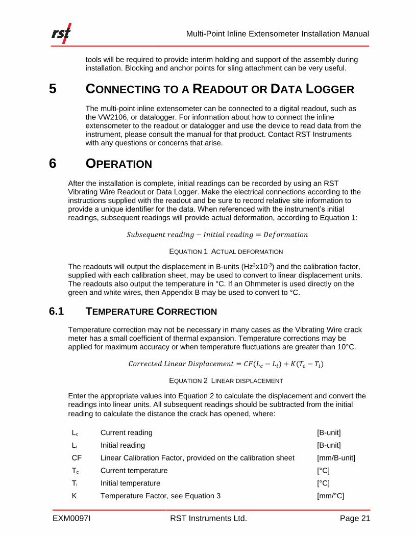
5 CONNECTING TO A READOUT OR DATA LOGGER
The multi-point inline extensometer can be connected to a digital readout, such as the VW2106, or datalogger. For information about how to connect the inline extensometer to the readout or datalogger and use the device to read data from the instrument, please consult the manual for that product. Contact RST Instruments with any questions or concerns that arise.
6 OPERATION
After the installation is complete, initial readings can be recorded by using an RST Vibrating Wire Readout or Data Logger. Make the electrical connections according to the instructions supplied with the readout and be sure to record relative site information to provide a unique identifier for the data. When referenced with the instrument’s initial readings, subsequent readings will provide actual deformation, according to Equation 1:
𝑆𝑢𝑏𝑠𝑒𝑞𝑢𝑒𝑛𝑡 𝑟𝑒𝑎𝑑𝑖𝑛𝑔 − 𝐼𝑛𝑖𝑡𝑖𝑎𝑙 𝑟𝑒𝑎𝑑𝑖𝑛𝑔 = 𝐷𝑒𝑓𝑜𝑟𝑚𝑎𝑡𝑖𝑜𝑛
EQUATION 1 ACTUAL DEFORMATION
The readouts will output the displacement in B-units (Hz2x10-3) and the calibration factor, supplied with each calibration sheet, may be used to convert to linear displacement units. The readouts also output the temperature in °C. If an Ohmmeter is used directly on the green and white wires, then Appendix B may be used to convert to °C.
6.1 TEMPERATURE CORRECTION
Temperature correction may not be necessary in many cases as the Vibrating Wire crack meter has a small coefficient of thermal expansion. Temperature corrections may be applied for maximum accuracy or when temperature fluctuations are greater than 10°C.
𝐶𝑜𝑟𝑟𝑒𝑐𝑡𝑒𝑑 𝐿𝑖𝑛𝑒𝑎𝑟 𝐷𝑖𝑠𝑝𝑙𝑎𝑐𝑒𝑚𝑒𝑛𝑡 = 𝐶𝐹(𝐿𝑐 − 𝐿𝑖) + 𝐾(𝑇𝑐 − 𝑇𝑖)
EQUATION 2 LINEAR DISPLACEMENT
Enter the appropriate values into Equation 2 to calculate the displacement and convert the readings into linear units. All subsequent readings should be subtracted from the initial
reading to calculate the distance the crack has opened, where:
Lc Current reading [B-unit]
Li Initial reading [B-unit]
CF Linear Calibration Factor, provided on the calibration sheet [mm/B-unit]
Tc Current temperature [°C]
Ti Initial temperature [°C]
K Temperature Factor, see Equation 3 [mm/°C]
Multi-Point Inline Extensometer Installation Manual
EXM0097I RST Instruments Ltd. Page 22
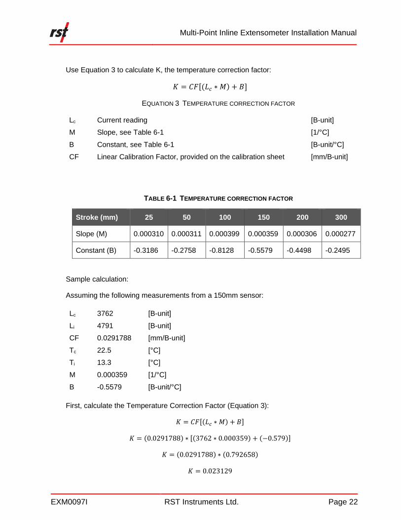
Use Equation 3 to calculate K, the temperature correction factor:
𝐾 = 𝐶𝐹[(𝐿𝑐 ∗ 𝑀) + 𝐵]
EQUATION 3 TEMPERATURE CORRECTION FACTOR
Lc Current reading [B-unit]
M Slope, see Table 6-1 [1/°C]
B Constant, see Table 6-1 [B-unit/°C]
CF Linear Calibration Factor, provided on the calibration sheet [mm/B-unit]
TABLE 6-1 TEMPERATURE CORRECTION FACTOR
Stroke (mm) 25 50 100 150 200 300
Slope (M) 0.000310 0.000311 0.000399 0.000359 0.000306 0.000277
Constant (B) -0.3186 -0.2758 -0.8128 -0.5579 -0.4498 -0.2495
Sample calculation:
Assuming the following measurements from a 150mm sensor:
Lc 3762 [B-unit]
Li 4791 [B-unit]
CF 0.0291788 [mm/B-unit]
Tc 22.5 [°C]
Ti 13.3 [°C]
M 0.000359 [1/°C]
B -0.5579 [B-unit/°C]
First, calculate the Temperature Correction Factor (Equation 3):
𝐾 = 𝐶𝐹[(𝐿𝑐 ∗ 𝑀) + 𝐵]
𝐾 = (0.0291788) ∗ [(3762 ∗ 0.000359) + (−0.579)]
𝐾 = (0.0291788) ∗ (0.792658)
𝐾 = 0.023129
Multi-Point Inline Extensometer Installation Manual
EXM0097I RST Instruments Ltd. Page 23
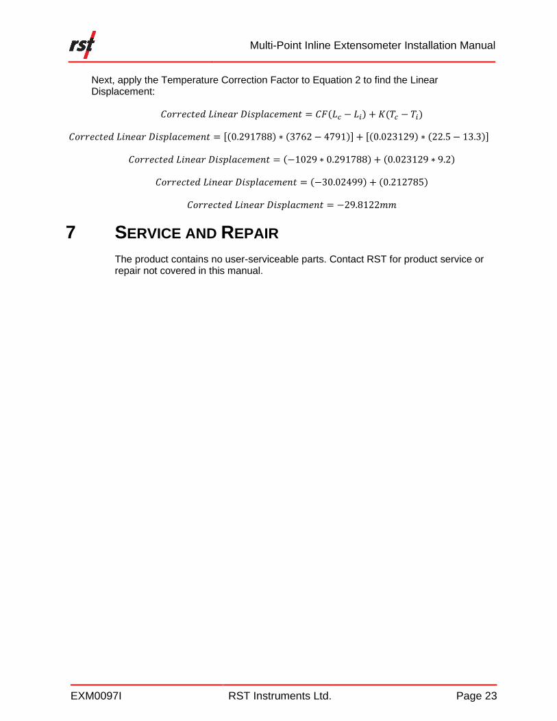
Next, apply the Temperature Correction Factor to Equation 2 to find the Linear Displacement:
𝐶𝑜𝑟𝑟𝑒𝑐𝑡𝑒𝑑 𝐿𝑖𝑛𝑒𝑎𝑟 𝐷𝑖𝑠𝑝𝑙𝑎𝑐𝑒𝑚𝑒𝑛𝑡 = 𝐶𝐹(𝐿𝑐 − 𝐿𝑖) + 𝐾(𝑇𝑐 − 𝑇𝑖)
𝐶𝑜𝑟𝑟𝑒𝑐𝑡𝑒𝑑 𝐿𝑖𝑛𝑒𝑎𝑟 𝐷𝑖𝑠𝑝𝑙𝑎𝑐𝑒𝑚𝑒𝑛𝑡 = [(0.291788) ∗ (3762 − 4791)] + [(0.023129) ∗ (22.5 − 13.3)]
𝐶𝑜𝑟𝑟𝑒𝑐𝑡𝑒𝑑 𝐿𝑖𝑛𝑒𝑎𝑟 𝐷𝑖𝑠𝑝𝑙𝑎𝑐𝑒𝑚𝑒𝑛𝑡 = (−1029 ∗ 0.291788) + (0.023129 ∗ 9.2)
𝐶𝑜𝑟𝑟𝑒𝑐𝑡𝑒𝑑 𝐿𝑖𝑛𝑒𝑎𝑟 𝐷𝑖𝑠𝑝𝑙𝑎𝑐𝑒𝑚𝑒𝑛𝑡 = (−30.02499) + (0.212785)
𝐶𝑜𝑟𝑟𝑒𝑐𝑡𝑒𝑑 𝐿𝑖𝑛𝑒𝑎𝑟 𝐷𝑖𝑠𝑝𝑙𝑎𝑐𝑚𝑒𝑛𝑡 = −29.8122𝑚𝑚
7 SERVICE AND REPAIR
The product contains no user-serviceable parts. Contact RST for product service or repair not covered in this manual.