2017 ChinaJoy展后报告5 / 40 士及技术开发人员等群体,形成了全球规模最大的数字化泛娱乐跨界融合、泛娱乐全生态产业交流和展示的服务平

Release Date: September, 2, 2004
Revision: 1.00
Preliminary Information
Documents Number:
For factory calibration and final test ATE Test Tool V2.1.0
MTK PRODUCTION LINE TEST TOOL
MediaTek

Application Note Preliminary Information For MTK atedemo Project
MediaTek Confidential Revision 0.06–May 5, 2004 Page: 2 of 64 © 2004 MediaTek Inc.
The information contained in this document can be modified without notice
Revision History
Revision Date Author Comments 0.01 6/01/2004 Ben Huang First release 0.02 9/2/2004 Ben Huang Add software design 1.00 11/10/2004 Ben Huang Add the description about ATE Tool V2.1.0
Application Note Preliminary Information For MTK atedemo Project
MediaTek Confidential Revision 0.06–May 5, 2004 Page: 3 of 64 © 2004 MediaTek Inc.
The information contained in this document can be modified without notice
Table of contents
Revision History .................................................................................................................................................... 2 Abstract .................................................................................................................................................................. 5 1 Introduction .................................................................................................................................................. 6
1.1 Overview.................................................................................................................................................. 6 1.2 Environment requirement ........................................................................................................................ 7
2 Installation .................................................................................................................................................... 8 3 Test system Setup ..................................................................................................................................... 12
3.1 System setup for CMU200 test platform................................................................................................ 12 3.2 System setup for Agilent 8960 test platform .......................................................................................... 13
4 Configuring a ATE Implementation .......................................................................................................... 14 4.1 Setup INI file introduction....................................................................................................................... 14
4.1.1 [Reset RF Function Group] section ................................................................................................. 14 4.1.2 [System Setting] section.................................................................................................................. 14 4.1.3 [Call Setup Configuration] section ................................................................................................... 16 4.1.4 [Signalling Measurement] section.................................................................................................... 18 4.1.5 [Calibration Setup] section .............................................................................................................. 22 4.1.6 [IMEI] section................................................................................................................................... 25 4.1.7 [Final Test TX Check] section.......................................................................................................... 25 4.1.8 [Barcode] section............................................................................................................................. 26 4.1.9 [Report Option] section.................................................................................................................... 27 4.1.10 [Error Code] section ........................................................................................................................ 27 4.1.11 [GSM xxx] section ........................................................................................................................... 29
4.2 ATE user interface introduction ............................................................................................................. 31 4.2.1 ATE Getting Start ............................................................................................................................ 32 4.2.2 Report & System setting.................................................................................................................. 32 4.2.3 Final test setting .............................................................................................................................. 33 4.2.4 Test Sequence Editor Getting Start................................................................................................. 34
4.3 ATE tool functions compare with META tool.......................................................................................... 37 4.4 Result and Test Report Format ............................................................................................................. 38
4.4.1 Test Status Display ......................................................................................................................... 38 4.4.2 Test report format............................................................................................................................ 39
5 GSM Testing Items for ATE tool ............................................................................................................... 40 5.1 GSM Standard Testing Items (For R&S CMU200 example).................................................................. 40
5.1.1 Location update test ........................................................................................................................ 40 5.1.2 TX measurement............................................................................................................................. 40 5.1.3 RX measurement ............................................................................................................................ 43
6 Test Setting major constraints check list ................................................................................................ 44 6.1 Final Test Constraints............................................................................................................................ 44 6.2 Calibration Test Constraints .................................................................................................................. 45 6.3 Combined Test Constraints ................................................................................................................... 45 6.4 Other Test Constraints........................................................................................................................... 45
7 ATE Design Specification.......................................................................................................................... 46 7.1 ATE software design introduction .......................................................................................................... 46 7.2 ATE project structure ............................................................................................................................. 48
7.2.1 ATE source code structure.............................................................................................................. 48
Application Note Preliminary Information For MTK atedemo Project
MediaTek Confidential Revision 0.06–May 5, 2004 Page: 4 of 64 © 2004 MediaTek Inc.
The information contained in this document can be modified without notice
7.2.2 Calibration test source code structure ............................................................................................. 50 7.2.3 Final source code structure ............................................................................................................. 52 7.2.4 INI file structure ............................................................................................................................... 54
7.3 Calibration Function Call........................................................................................................................ 55 7.3.1 META initial function code............................................................................................................... 55 7.3.2 AFC calibration source code structure ............................................................................................ 55 7.3.3 Pathloss calibration source code structure...................................................................................... 56 7.3.4 APC calibration source code structure ............................................................................................ 57 7.3.5 APC check calibration source code structure.................................................................................. 59 7.3.6 ADC calibration source code structure ............................................................................................ 59
7.4 Final test function call ............................................................................................................................ 61 7.4.1 ATE can approach GSM/GPRS complete test functions................................................................. 61 7.4.2 The ATE test sequence source code structure................................................................................ 61 7.4.3 Parallel test module......................................................................................................................... 63
Figures Index ....................................................................................................................................................... 64

Application Note Preliminary Information For MTK atedemo Project
MediaTek Confidential Revision 0.06–May 5, 2004 Page: 5 of 64 © 2004 MediaTek Inc.
The information contained in this document can be modified without notice
Abstract
This program is use to the production line auto test software, ATE can control the following instrument, such as R&S CMU200, Agilent 8960, and power supply include R&S NGSM, Agilnt 663xx serial, It can test all important items for the MTK GSM chipset calibration (including GSM, DCS, PCS triple band), the detail items include the AFC calibration, pathloss calibration, APC calibration, ADC calibration, and the others is the final test, the most of important GSM standard test include in this ATE program, such as average power, peak power, power vs time, spectrum due to Modulation, spectrum due to switching, RX level, RX quality, Class II, Class Ib, Phase error peak, phase error RMS, frequency error …etc.
The ATE design concept is easy to use and modify that based on a simple development environment, so the program syntax here is ANSI C, and the user interface is a big screen for test status display, because the ATE is used in the production line, we used the National Instrument Labwindows/CVI7.0 to develop this program, because the CVI is a professional development environment for auto test system design, and for the control instrument, we used the separate driver to control instrument, and almost all functions in this driver, for this reason, we can add the advance testing items easily . This paper separate seven chapters, chapter 1 discusses the production line requirement of our customer and ATE tool can approach status, chapter 2 discusses how to install the program, chapter 3 discusses how to setup the test environment, chapter 4 discusses that how to use the ATE tool and configuring a ATE implementation, chapter 5 discusses the GSM testing items, chapter 6 is about setting constraints, chapter 7 discusses about how to design ATE program and important functions in the program, chapter 7 is the ATE design document that will tell you how to modify the source code and integrate the MTK calibration into your test platform.
Application Note Preliminary Information For MTK atedemo Project
MediaTek Confidential Revision 0.06–May 5, 2004 Page: 6 of 64 © 2004 MediaTek Inc.
The information contained in this document can be modified without notice
1 Introduction
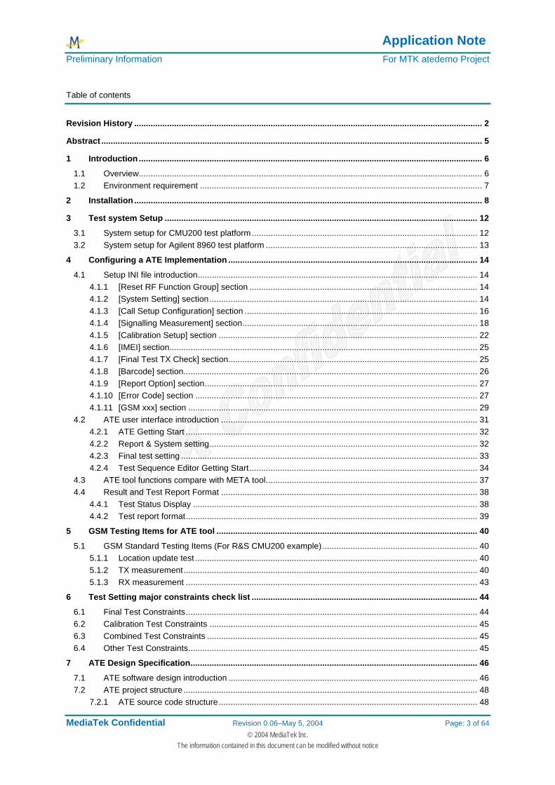
1.1 Overview MTK ate (Media Tek automatic test environment) This program is used in the production line test, So the user interface is force on the easy to use, there are some parameter s can be set on the user interface, when do the test, usually production line require three type test stations, such as : 1. Final test station(Cable line) or Wireless test station(Air link) 2. Calibration test station 3. Combined mode test station For this reason, ATE can enable for test station that above mentioned, If customer need to establish production line directly, just do some setting, a lot of setting is using the read ini file concept, this is a very convenient for the user, if want to do some modify the test parameter, don’t need to modify the source code, just change the setting of the INI file, the ATE tool can do the calibration test in the META mode and final test in the normal mode. The following chart is showing the real production line, you can understand the ATE tool application.
Figure 1 MTK Production line test solution
Application Note Preliminary Information For MTK atedemo Project
MediaTek Confidential Revision 0.06–May 5, 2004 Page: 7 of 64 © 2004 MediaTek Inc.
The information contained in this document can be modified without notice
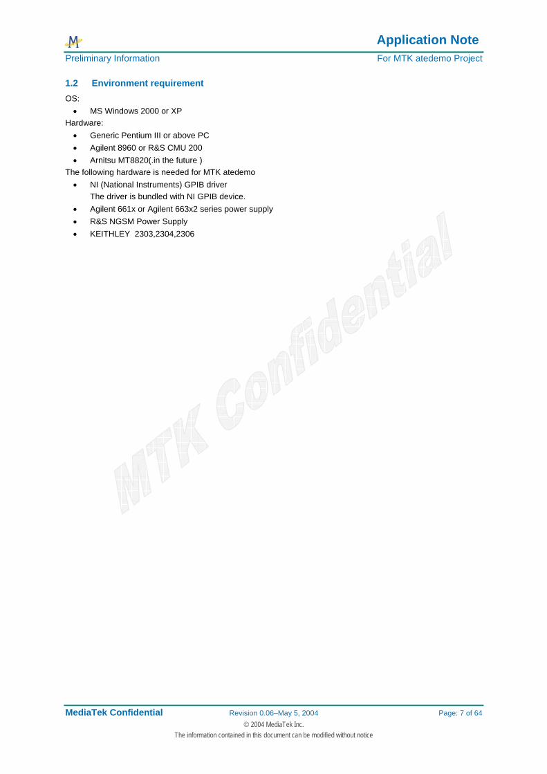
1.2 Environment requirement OS: • MS Windows 2000 or XP
Hardware: • Generic Pentium III or above PC • Agilent 8960 or R&S CMU 200 • Arnitsu MT8820(.in the future )
The following hardware is needed for MTK atedemo • NI (National Instruments) GPIB driver
The driver is bundled with NI GPIB device. • Agilent 661x or Agilent 663x2 series power supply • R&S NGSM Power Supply • KEITHLEY 2303,2304,2306
Application Note Preliminary Information For MTK atedemo Project
MediaTek Confidential Revision 0.06–May 5, 2004 Page: 8 of 64 © 2004 MediaTek Inc.
The information contained in this document can be modified without notice
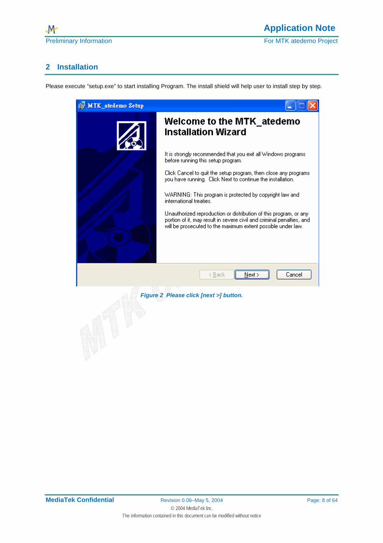
2 Installation
Please execute “setup.exe” to start installing Program. The install shield will help user to install step by step.
Figure 2 Please click [next >] button.

Application Note Preliminary Information For MTK atedemo Project
MediaTek Confidential Revision 0.06–May 5, 2004 Page: 9 of 64 © 2004 MediaTek Inc.
The information contained in this document can be modified without notice
Figure 3 Please select a directory to install and then click [next >] button.
The ATE Program will be installed at C:\Program Files\MTK_atedemo\. The install shield will help user to install step by step, and please remember to add the folder into C:\Program Files\MTK_atedemo\ for restore the test report , please remember to copy the chipset database file into your folder like BPLGUInfoCustom, The test report will put into the place that you specify location, and if you do the calibration test , program need to read database file first,.
Figure 4 The files in the MTK_atedemo folder.
You can add some folder that put into the special file like BPLGUInfoCustom
Application Note Preliminary Information For MTK atedemo Project
MediaTek Confidential Revision 0.06–May 5, 2004 Page: 10 of 64 © 2004 MediaTek Inc.
The information contained in this document can be modified without notice
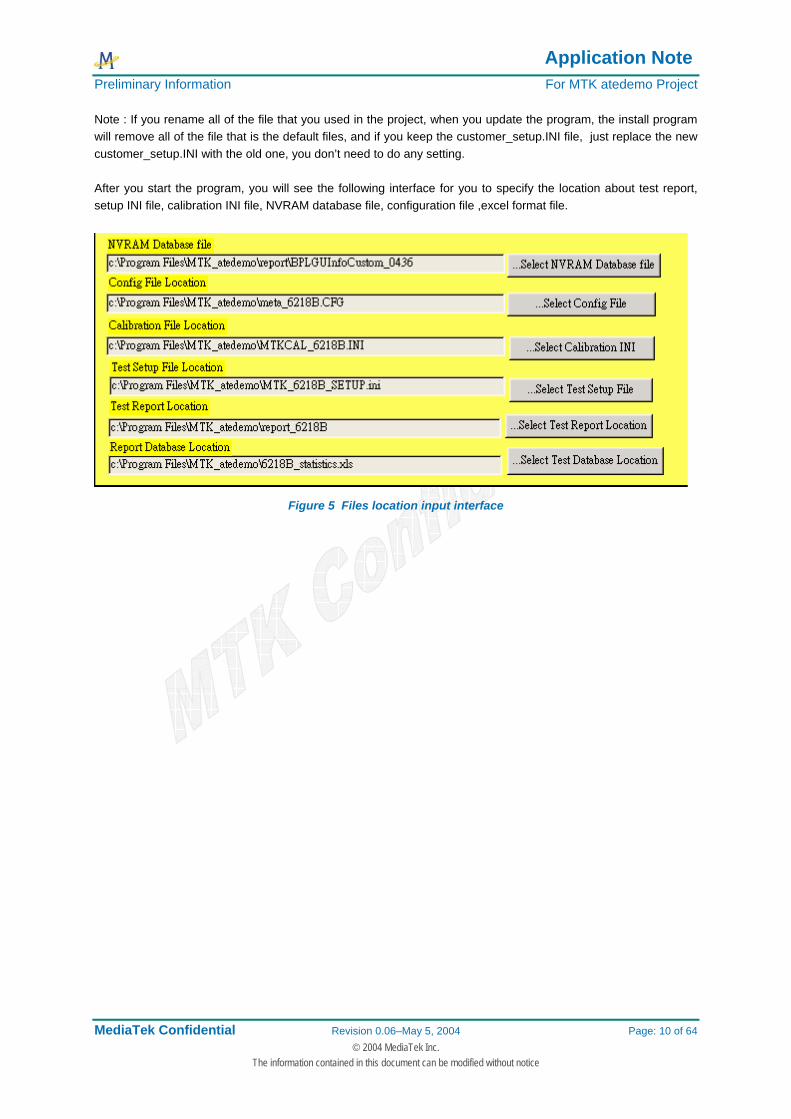
Note : If you rename all of the file that you used in the project, when you update the program, the install program will remove all of the file that is the default files, and if you keep the customer_setup.INI file, just replace the new customer_setup.INI with the old one, you don’t need to do any setting.
After you start the program, you will see the following interface for you to specify the location about test report, setup INI file, calibration INI file, NVRAM database file, configuration file ,excel format file.
Figure 5 Files location input interface
Application Note Preliminary Information For MTK atedemo Project
MediaTek Confidential Revision 0.06–May 5, 2004 Page: 11 of 64 © 2004 MediaTek Inc.
The information contained in this document can be modified without notice
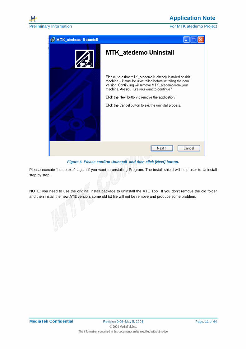
Figure 6 Please confirm Uninstall and then click [Next] button.
Please execute “setup.exe” again if you want to unstalling Program. The install shield will help user to Uninstall step by step. NOTE: you need to use the original install package to uninstall the ATE Tool, If you don’t remove the old folder and then install the new ATE version, some old txt file will not be remove and produce some problem.

Application Note Preliminary Information For MTK atedemo Project
MediaTek Confidential Revision 0.06–May 5, 2004 Page: 12 of 64 © 2004 MediaTek Inc.
The information contained in this document can be modified without notice
3 Test system Setup
3.1 System setup for CMU200 test platform
Agilent 663xx
CMU200 Power Supply Cable
RF Cable (Inner Cable)
Figure 7 CMU Test Enviroment.
Note: For the CMU200, some of the application will use the port of RF1 or RF2, (If you have CMU option about B99,you can select RF1/RF2 switch), we recommend that you can use the RF2, because RF1 is used for high power detect, the accuracy maybe not enough when you read the general GSM power, for the cable loss compensate, you can see it define in the setup INI file, the following example is show how to setup GSM cable loss in the setup INI file. This application is used for CNU200 test platform. For example: [Signalling Measurement] GSM Output Loss = 0.6 GSM Input Loss = 0.6
NOTE: precondition is Wireless Test = 0
Test Fixture
RF Cable (Outside Cable)
NI GPIB Cable
RS232 Cable
NI GPIB Cable
Application Note Preliminary Information For MTK atedemo Project
MediaTek Confidential Revision 0.06–May 5, 2004 Page: 13 of 64 © 2004 MediaTek Inc.
The information contained in this document can be modified without notice
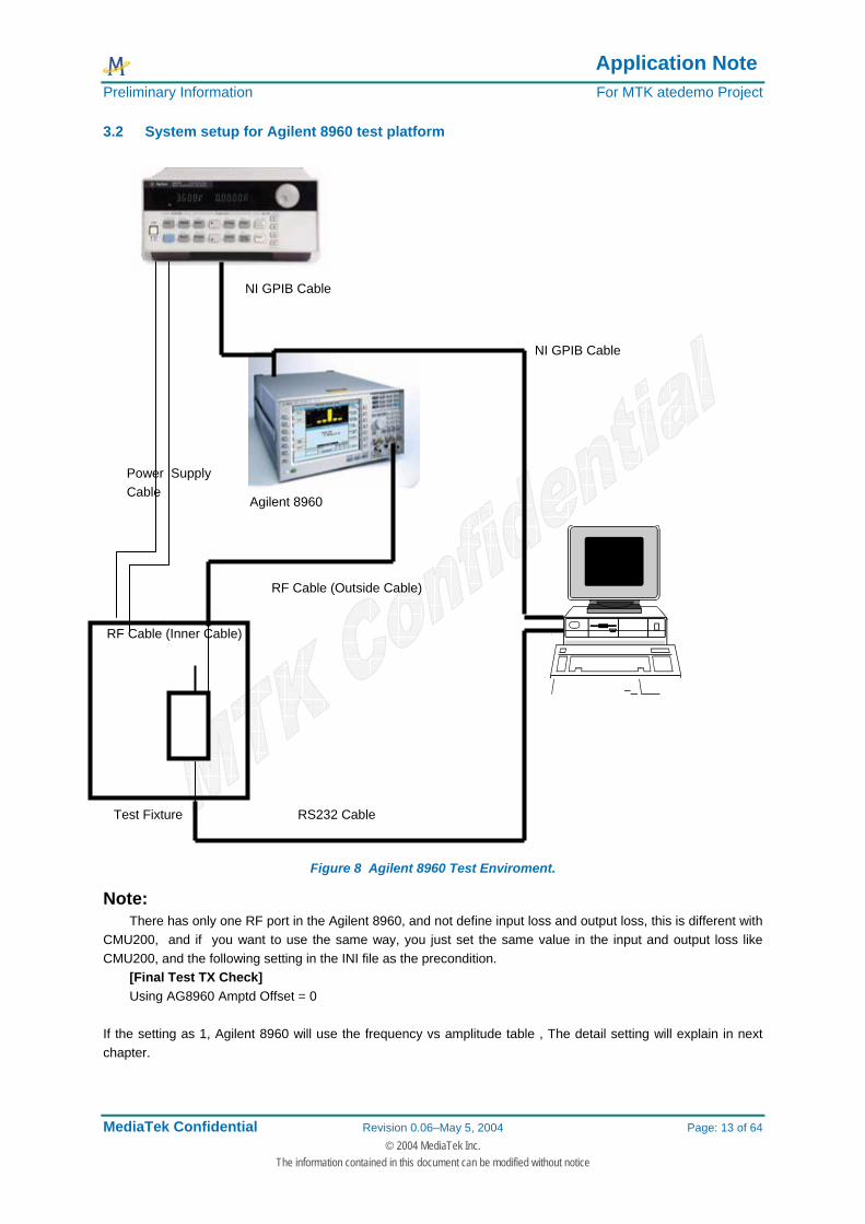
3.2 System setup for Agilent 8960 test platform
Agilent 8960
RF Cable (Inner Cable)
Figure 8 Agilent 8960 Test Enviroment.
Note: There has only one RF port in the Agilent 8960, and not define input loss and output loss, this is different with
CMU200, and if you want to use the same way, you just set the same value in the input and output loss like CMU200, and the following setting in the INI file as the precondition.
[Final Test TX Check] Using AG8960 Amptd Offset = 0
If the setting as 1, Agilent 8960 will use the frequency vs amplitude table , The detail setting will explain in next chapter.
Test Fixture
RF Cable (Outside Cable)
NI GPIB Cable
RS232 Cable
NI GPIB Cable
Power Supply Cable
Application Note Preliminary Information For MTK atedemo Project
MediaTek Confidential Revision 0.06–May 5, 2004 Page: 14 of 64 © 2004 MediaTek Inc.
The information contained in this document can be modified without notice
4 Configuring a ATE Implementation
4.1 Setup INI file introduction
4.1.1 [Reset RF Function Group] section
The following items are defined in the setup INI file. GSM900 Sig = 1 GSM1800 Sig = 1 GSM1900 Sig = 1 GSM900 NSig = 1 GSM1800 NSig = 1 GSM1900 NSig = 1
The general setting as 1,that means the program will reset the instrument before configuring, set 1 is to do and set 0 is skip, generally, we just define all of the items as 1 , this setting is used for CMU200 only, because each function group is the different handles of the CMU200 .
4.1.2 [System Setting] section
The following items are defined in the setup INI file.
External Reference Clock = 0 This item is used the CMU200 reference clock output to synchronize other CMU200 if your setting as 1, The
default value as 0, and CMU200 usually use the internal clock to test target
CMU Base GPIB Address = 20 This define the CMU Base GPIB address, before you want to remote the CMU200, just make sure that the
CMU200 base GPIB address is equal to the setting NOTE: Agilent 8960 GPIB address is define in the CFG file
Instrument = "CMU200" This item define which instrument in your system, of course, the setting is “CMU2000” for CMU200 remote
control , and if the setting is “AG8960” for Agilent 8960 remote control.
Power Supply Address = GPIB0::5::INSTR This item define the power supply GPIB address, you can see the define “GPIB0::5::INSTR”, that means the
GPIB board is the first GPIB card and address is 5, if your power supply is R&S NGSM, please notice the GPIB address define like “GPIB::16::INSTR”, a little different with the normal power supply setting. If your power supply is agilent 663xx serial, the setting is “Power Supply Address = GPIB0::5::INSTR”
If your power supply is keithley 2303,2304, the setting is “Power Supply Address = 5” If your power supply is keithley 2306, the setting is “Power Supply Address = GPIB0::5::INSTR”
CMU RF Port = 2 This item define the RF port of CMU200, generally we used the RF2 for cable link test, as you can see
setting as 2 , That measurement RF port is RF2, and if the setting as 1, CMU RF port is RF1.
Debug Mode = 2

Application Note Preliminary Information For MTK atedemo Project
MediaTek Confidential Revision 0.06–May 5, 2004 Page: 15 of 64 © 2004 MediaTek Inc.
The information contained in this document can be modified without notice
This item general define as 2, other value is different saturation depend on your application or PC status
Test Mode = 0 Setting as 0 that means you need to initial the instrument by yourself, and if the setting as 1, the program will
automatic initialized when do the final test, setting as 2 that the program will initialize when do the calibration test automatically, set ting as 3 that the program will initialize in the combined mode test automatically.
FDM database file = "c:\\Program Files\\MTK_atedemo\\report\\BPLGUInfoCustom"
This define the NVRAM database location, before you want to do the calibration test, please make sure that you are using the right NVRAM database, if you are not, you can see some fail and show the META error on the display of test information and display error code panel.
Calibration file = "c:\\Program Files\\MTK_atedemo\\MTKCAL_6205B.INI"
This file define the calibration default value and you must be select the file location, the program will read the file before the calibration test, this INI file is almost the well define file for MTK solution.
Config file = "c:\\Program Files\\MTK_atedemo\\meta_6205B.CFG"
This file defines the calibration setting, CFG file that include the calibration channel, maximum and minimum value for check limit,
Report file path = "c:\\Program Files\\MTK_atedemo\\report_6218B" We can define the location that the place where the test report will be stored
Database file = "c:\\Program Files\\MTK_atedemo\\Report_Statistics\\6218B_statistics.xls" This excel file is used for statistic the test result, you can define the location that the file is exist, it work with
excel 2000 and your OS is Windows 2000
IMSI = "001010123456789" IMSI number that is defined in the test SIM card, so if different test SIM card, please notice that you must be
key in the correct number before you want to do the final test.
POWER ON AFTER CHANGE = 1 For the Combined mode test, if the instrument change to different system is too slow, it should be set as 1.
Stability Count = 1 If the setting as 1, this is normal condition, and if you want to do the loop test or stability test, you can set the
value more than 1, If your “Bar code get type when calibration “ as Scan barcode and stability more than 1, the Barcode scan input box will show without push start to test button.
Check Testfixture = 0
If your setting as 1, the ATE Tool will control TESCOM test fixture automatically
Fixture COM port = 1 Test fixture COM port setting
System Cable Loss Calibration = 0 If the setting as 1, when you do the final test, ATE Tool will adjust the cable loss automatically, and please note that this functions can work in the Wireless Test = 1, it will use the input loss or output loss under [GSM 1] section.(just for CMU200 only)
System Input Calibration = 1 If the setting as 1, it means enable the System Input Calibration
Application Note Preliminary Information For MTK atedemo Project
MediaTek Confidential Revision 0.06–May 5, 2004 Page: 16 of 64 © 2004 MediaTek Inc.
The information contained in this document can be modified without notice
System Output Calibration = 1
If the setting as 1, it means enable the System Output Calibration
4.1.3 [Call Setup Configuration] section
Setup Network = 1
If setting as 1,that means the call setup is GSM system, and if the setting as 2, that means the call setup is DCS system and if the setting as 3, that means the call setup is PCS system. Normal case we will define in the GSM system when establish the call.
GSM Call Setup Channel = 1 GSM BCCH Channel = 32 DCS Call Setup Channel = 512 DCS BCCH Channel = 700 PCS Call Setup Channel = 512 PCS BCCH Channel = 700 GSM850 Call Setup Channel = 128 GSM850 BCCH Channel = 128
Note: GSM850 is only for CMU200 only now, and just to do GSM 850 final test Above items is define the call setup channel, if the define is established in the GSM system, the established
call of TCH is channel 1 if the GSM Call Setup Channel setting as 1
BCCH RF LEVEL = -60 BS TCH LEVEL = -80.5
Above items is define the downlink power.
Triple Band = 0 If the setting as 1, the final test will do the PCS band measurement, our solution has dual band mode and
PCS band mode, please make sure that the RS232 cable must be connect with target, because it must be send the AT command to change the target into the PCS band after dual band test, when enter into PCS band success and then ATE tool can do the PCS band final test.
DCS Band = 1
If the setting as 1 ,that means to enable DCS band final test GSM Band = 1
If the setting as 1 ,that means to enable GSM band final test
GSM850 Band = 0 If the setting as 1 ,that means to enable GSM850 band final test
GPRS TEST = 0 If the setting as 1,the final test will do the GPRS test after dual band test, GPRS test require the correct
setting, right setting will establish the GPRS connection, and then ATE can do the GPRS test. The following items are defined the GPRS test downlink slot, setting as 1 that means is selected and 0 is not selected. All of this setting are used with the CMU200 test platform
MSlot0 Downlink = 0

Application Note Preliminary Information For MTK atedemo Project
MediaTek Confidential Revision 0.06–May 5, 2004 Page: 17 of 64 © 2004 MediaTek Inc.
The information contained in this document can be modified without notice
MSlot1 Downlink = 0 MSlot2 Downlink = 0 MSlot3 Downlink = 1 MSlot4 Downlink = 0 MSlot5 Downlink = 0 MSlot6 Downlink = 0 MSlot7 Downlink = 0
The following items are defined in the GPRS test, these are uplink slots, setting as 1 is selected and 0 is not selected. All of this setting is used with the CMU200 test platform
MSlot0 Uplink = 0 MSlot1 Uplink = 0 MSlot2 Uplink = 0 MSlot3 Uplink = 1 MSlot4 Uplink = 0 MSlot5 Uplink = 0 MSlot6 Uplink = 0 MSlot7 Uplink = 0
MSlot0 Relative Level = 0 MSlot1 Relative Level = 0 MSlot2 Relative Level = 6 MSlot3 Relative Level = 0 MSlot4 Relative Level = 6 MSlot5 Relative Level = 6 MSlot6 Relative Level = 0 MSlot7 Relative Level = 0
The following items are defined in the GPRS test, these are output power of uplink slots, and all of this setting is used with the CMU200 test platform
MSlot0 Gamma = 3 MSlot1 Gamma = 3 MSlot2 Gamma = 3 MSlot3 Gamma = 3 MSlot4 Gamma = 3 MSlot5 Gamma = 3 MSlot6 Gamma = 3 MSlot7 Gamma = 3
BLER Reference Level = -85 Individual Level BLERS0 = 0 Individual Level BLERS1 = 0 Individual Level BLERS2 = -2.000000000000001 Individual Level BLERS3 = -10 Individual Level BLERS4 = 0 Individual Level BLERS5 = 0 Individual Level BLERS6 = 0
Application Note Preliminary Information For MTK atedemo Project
MediaTek Confidential Revision 0.06–May 5, 2004 Page: 18 of 64 © 2004 MediaTek Inc.
The information contained in this document can be modified without notice
Individual Level BLERS7 = 0 RLC Blocks = 1000
4.1.4 [Signalling Measurement] section
Power Measment Burst = 10
Define how many bursts power to be measurement
Average Burst Power = 1 To do the average burst power measurement
Peak Burst Power = 1 To do the peak burst power measurement
PVT Match = 1 To do the power vs time check
Timing Error = 1 To de the timing advance measurement
Modulation Measment Burst = 10 Define how many bursts for the modulation measurement
Phase Error Peak = 1 To do the phase error peak measurement
Phase Error RMS = 1 To do the phase error RMS measurement
Frequency Error = 1 To do the frequency error measurement
ORFS MOD Burst = 10 Define how many bursts for the spectrum due to modulation measurement
Spectrum Modulation = 1
To do the spectrum due to modulation measurement
ORFS Switch Burst = 10 Define how many bursts for the spectrum due to switching measurement
Spectrum Switch = 1 To do the spectrum due to switching measurement
Rx Quality = 0
Application Note Preliminary Information For MTK atedemo Project
MediaTek Confidential Revision 0.06–May 5, 2004 Page: 19 of 64 © 2004 MediaTek Inc.
The information contained in this document can be modified without notice
To do the receiver quality measurement
RX Level = 0 To do the receiver level measurement
RFER = 0 To do the RFER measurement, For the CMU200, it will use Class II measurement with codec ,the same as
Agilent 8960
BBB = 1 To do the burst by burst BER measuremen(CMU200 Fast BER measurement)t, it will use Class II
measurement with codec ,the same as Agilent 8960(Fast BER measurement)
GSM Rx Meas Level = -100 Define the measurement level for GSM BER test
DCS Rx Meas Level = -100 Define the measurement level for DCS BER test
PCS Rx Meas Level = -100 Define the measurement level for PCS BER test
Rx RFER Burst = 128
Define how many bursts for RFER measurement, generally, the value as 128, this setting is equal to 10000 bits measurement (about 78 bits * 128 burst).
NOTE: If the setting as 128 with CMU200, equal to Agilent 8960 as 10000bit
Rx BBB Burst = 88 Define how many bursts for Burst-By-Burst test, generally, the value setting as 88, this setting is equal to
10000 bites measurement (about 114 bits * 88 burst). NOTE: If the setting as 88 with CMU200, equal to Agilent 8960 as 10000bit
GSM Output Loss = 0.6 This setting define the GSM output cable loss for the GSM signaling measurement with CMU200 only
GSM Input Loss = 0.6 This setting define the GSM input cable loss for the GSM signaling measurement with CMU200 only
DCS Out Loss = 1.2 This setting define the DCS output cable loss for the DCS signaling measurement with CMU200 only
DCS Inp Loss = 1.2 This setting define the DCS input cable loss for the DCS signaling measurement with CMU200 only
PCS Out Loss = 1.3 This setting define the PCS output cable loss for the PCS signaling measurement with CMU200 only
PCS Inp Loss = 1.3 This setting define the PCS input cable loss for the PCS signaling measurement with CMU200 only
Application Note Preliminary Information For MTK atedemo Project
MediaTek Confidential Revision 0.06–May 5, 2004 Page: 20 of 64 © 2004 MediaTek Inc.
The information contained in this document can be modified without notice
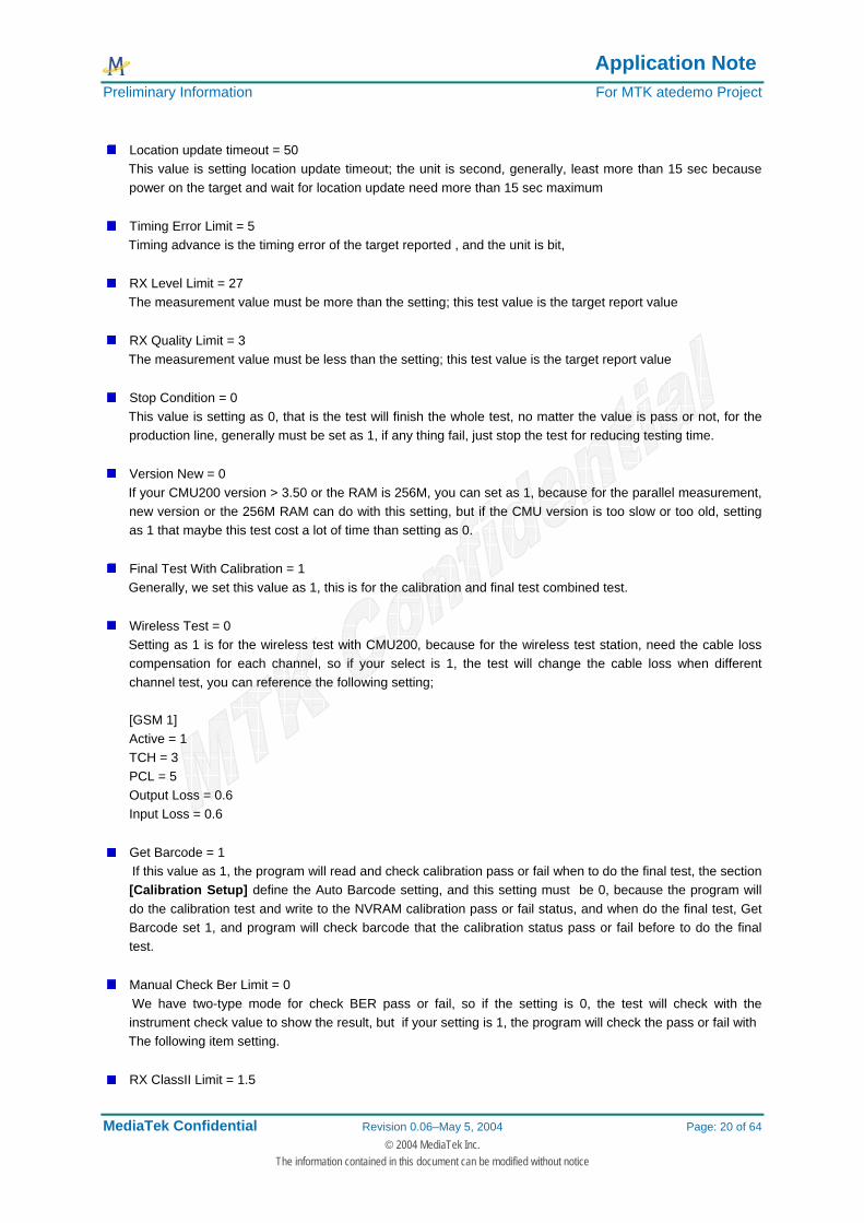
Location update timeout = 50
This value is setting location update timeout; the unit is second, generally, least more than 15 sec because power on the target and wait for location update need more than 15 sec maximum
Timing Error Limit = 5
Timing advance is the timing error of the target reported , and the unit is bit,
RX Level Limit = 27 The measurement value must be more than the setting; this test value is the target report value
RX Quality Limit = 3 The measurement value must be less than the setting; this test value is the target report value
Stop Condition = 0 This value is setting as 0, that is the test will finish the whole test, no matter the value is pass or not, for the
production line, generally must be set as 1, if any thing fail, just stop the test for reducing testing time.
Version New = 0 If your CMU200 version > 3.50 or the RAM is 256M, you can set as 1, because for the parallel measurement,
new version or the 256M RAM can do with this setting, but if the CMU version is too slow or too old, setting as 1 that maybe this test cost a lot of time than setting as 0.
Final Test With Calibration = 1
Generally, we set this value as 1, this is for the calibration and final test combined test.
Wireless Test = 0 Setting as 1 is for the wireless test with CMU200, because for the wireless test station, need the cable loss
compensation for each channel, so if your select is 1, the test will change the cable loss when different channel test, you can reference the following setting;
[GSM 1] Active = 1 TCH = 3 PCL = 5 Output Loss = 0.6 Input Loss = 0.6
Get Barcode = 1
If this value as 1, the program will read and check calibration pass or fail when to do the final test, the section [Calibration Setup] define the Auto Barcode setting, and this setting must be 0, because the program will do the calibration test and write to the NVRAM calibration pass or fail status, and when do the final test, Get Barcode set 1, and program will check barcode that the calibration status pass or fail before to do the final test.
Manual Check Ber Limit = 0
We have two-type mode for check BER pass or fail, so if the setting is 0, the test will check with the instrument check value to show the result, but if your setting is 1, the program will check the pass or fail with
The following item setting.
RX ClassII Limit = 1.5

Application Note Preliminary Information For MTK atedemo Project
MediaTek Confidential Revision 0.06–May 5, 2004 Page: 21 of 64 © 2004 MediaTek Inc.
The information contained in this document can be modified without notice
This setting is working when the above setting(Manual Check Ber Limit) is 1, the program will check pass or fail with this item’s setting
RX ClassIb Limit = 1.5 This setting is working when the above setting(Manual Check Ber Limit) is 1, the program will check pass or
fail with this item’s setting
Default Test Items = 1 For the final test, the program provide two type test mode, if the Default Test Items is 1, the test items will
following the above items that define in the [Signalling Measurement] section, and if your setting is 0, the test items will following the [GSM xx] section define items to do the measurement, on other words, if user need to do the final test with different items when do the different channel, just setting this to 0.
Test Fixture = 1
Generally, this setting is 1, and when do the final test, there is not message display to show that tell you open the target, and if yours setting is 1, popup message will hit you to open on your target.
Code Scheme = 3
This setting is for the GPRS coding scheme setting. Generally the value is 1 to 4.
Check BarCode Delay = 15.0 When do the final test, if your application is need to check calibration status first, and need to read the
barcode, this setting is wait for the target power on, because if you want to get barcode by AT command stability, you need wait some times for target power on.
GPRS TEST MODE = 1
The setting 1 is for BLER test with CMU200 and Agilent 8960, The setting 2 1i for test mode B for CMU200 and TYPE B for Agilent 8960
Handover Delay Time = 0.5 This setting is the delay time of the handover, some target maybe need wait for some time to transfer do the
handover
BER MEAS MODE = 0 This setting 0 is used for single shot measurement with CMU200, and the setting 1 is used for continue
measurement, if your setting is 1, the following item define the delay time for continue measurement.
BER Continuous Meas Delay = 1.5 define the measurement delay time when do the BER continue measurement.
Mobile Repore RxQ Delay = 1.5 Receiver quality report by the target, and if you want to get the correct value, you must be wait for your
target return the correct value, the generally delay time is 1.5 sec
TX Limit Check by Tester = 1 If the setting is 1, the limit check will use the [Final Test TX Check] that define in your setup INI file,
generally, the setting is 1, because if your limit is by test equipment, maybe the instrument will have the wrong value, so check the limit that your define is the batter way.

Application Note Preliminary Information For MTK atedemo Project
MediaTek Confidential Revision 0.06–May 5, 2004 Page: 22 of 64 © 2004 MediaTek Inc.
The information contained in this document can be modified without notice
Write pass status to Target = 0 This function will enable in the future, but now not yet.
MT Call = 0 If the setting as 0, it means ATE Tool will use the MO(Mobile original call) , this setting is Mobile will call to
the instrument until connect to the equipment. So, this setting need the RS232 cable to send the AT Command like “ATD112;”, If the setting as 1, that means the instrument will call to the Mobile, the mode can work without TEST SIM, but please note the IMSI number is correctly or it can’t location update success
GSM850 Rx Meas Level = -100
This function work precondition is the “default testing items” as 1, ATE will use this value to measurement the BER
6218B Normal Baud Rate = 115200
You can define the chip baud rate by yourself, generally, the 6218B chip baud rate as 115200
6205B Normal Baud Rate = 57600 You can define the chip baud rate by yourself, generally, the 6205B chip baud rate as 115200
RX Level Limit MAX = 31 You can define the RX level max limit
4.1.5 [Calibration Setup] section
GSMN OUT LOSS = 0.6 This setting is used for CMU200 GSM nonsignaling measurement cable loss
GSMN INP LOSS = 0.6 This setting is used for CMU200 GSM nonsignaling measurement cable loss, and if your test equipment is
Agilent 8960, It will set the amplitude to the Agilent, but you must be set the Using AG8960 Amptd Offset is 0 in the [Final Test TX Check] section.
DCSN OUT LOSS = 1.2
This setting is used for CMU200 DCS nonsignaling measurement cable loss
DCSN INP LOSS = 1.2 This setting is used for CMU200 DCS nonsignaling measurement cable loss, and if your test equipment is
Agilent 8960, It will set the amplitude to the Agilent, but you must be set the Using AG8960 Amptd Offset is 0 in the [Final Test TX Check] section.
COM PORT = 4
The COM port setting value is 1 to 8
Check IMEI = 0 This is IMEI check sum, this function is for feature if have customer requirement.
Auto Barcode = 0 The setting 1 is the system generate barcode automatically, and the start value define in the [Barcode]
section like the following example [Barcode]

Application Note Preliminary Information For MTK atedemo Project
MediaTek Confidential Revision 0.06–May 5, 2004 Page: 23 of 64 © 2004 MediaTek Inc.
The information contained in this document can be modified without notice
Barcode = "0007" Barcode Step = 1
The barcode will add the step value when each test, please note that if your setting is like the following
example: Barcode = "S4716A0007 10"
This is used when Auto Barcode is 0, when do the calibration or combined mode test, system will add
pass or fail status in char[60] and char[61]. 11 is calibration not yet 10 is calibration is pass
01 is calibration is fail If the setting is Auto Barcode = 0, the barcode number will like the following example: 0721030022 It means the report has been generated date 07/21 and the test station is 03, 0022 is that the means 22
times measurement Barcode number is the test report name.
Auto Barcode Step = 1 The bar code number increase step when your application is Auto barcode =1
ADC Calibration = 0 The setting 0 is calibration without ADC calibration, and the program do not control power supply, so if the
user don’t have the power supply that programmable, the user can set the value to 0, it means that control power supply manually, and if your setting is 1, the calibration will test with ADC calibration.
AG8960 GSM = 0
The setting 0 is means your Agilent 8960 is GSM/GPRS combined mode, like the version is 1968A, or if the setting as1, your Agilent 8960 is the GSM mode only like 1960A.
Power Supply Type = 0
The setting 0 is for the Agilent 663xx power supply and 1 is for R&S NGSM
Frequency Bank with PCS = 0 This means to do the PCS band calibration
BB Chip Type = "6205B" The setting is “6205B” for 6205B chipset The setting is “6218B” for 6218B chipset
CO GSM900 = 70 Read the calibration GSM channel from CFG file
CO DCS1800 = 700 Read the calibration DCS channel from CFG file
Application Note Preliminary Information For MTK atedemo Project
MediaTek Confidential Revision 0.06–May 5, 2004 Page: 24 of 64 © 2004 MediaTek Inc.
The information contained in this document can be modified without notice
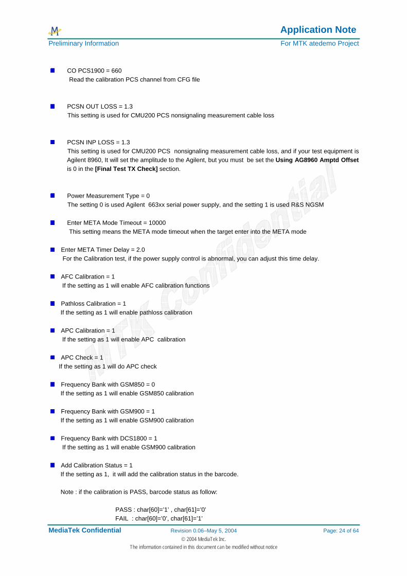
CO PCS1900 = 660
Read the calibration PCS channel from CFG file
PCSN OUT LOSS = 1.3 This setting is used for CMU200 PCS nonsignaling measurement cable loss
PCSN INP LOSS = 1.3 This setting is used for CMU200 PCS nonsignaling measurement cable loss, and if your test equipment is
Agilent 8960, It will set the amplitude to the Agilent, but you must be set the Using AG8960 Amptd Offset is 0 in the [Final Test TX Check] section.
Power Measurement Type = 0 The setting 0 is used Agilent 663xx serial power supply, and the setting 1 is used R&S NGSM
Enter META Mode Timeout = 10000 This setting means the META mode timeout when the target enter into the META mode
Enter META Timer Delay = 2.0 For the Calibration test, if the power supply control is abnormal, you can adjust this time delay.
AFC Calibration = 1 If the setting as 1 will enable AFC calibration functions
Pathloss Calibration = 1 If the setting as 1 will enable pathloss calibration
APC Calibration = 1 If the setting as 1 will enable APC calibration
APC Check = 1 If the setting as 1 will do APC check
Frequency Bank with GSM850 = 0 If the setting as 1 will enable GSM850 calibration
Frequency Bank with GSM900 = 1 If the setting as 1 will enable GSM900 calibration
Frequency Bank with DCS1800 = 1 If the setting as 1 will enable GSM900 calibration
Add Calibration Status = 1 If the setting as 1, it will add the calibration status in the barcode. Note : if the calibration is PASS, barcode status as follow: PASS : char[60]=’1’ , char[61]=’0’ FAIL : char[60]=’0’, char[61]=’1’
Application Note Preliminary Information For MTK atedemo Project
MediaTek Confidential Revision 0.06–May 5, 2004 Page: 25 of 64 © 2004 MediaTek Inc.
The information contained in this document can be modified without notice
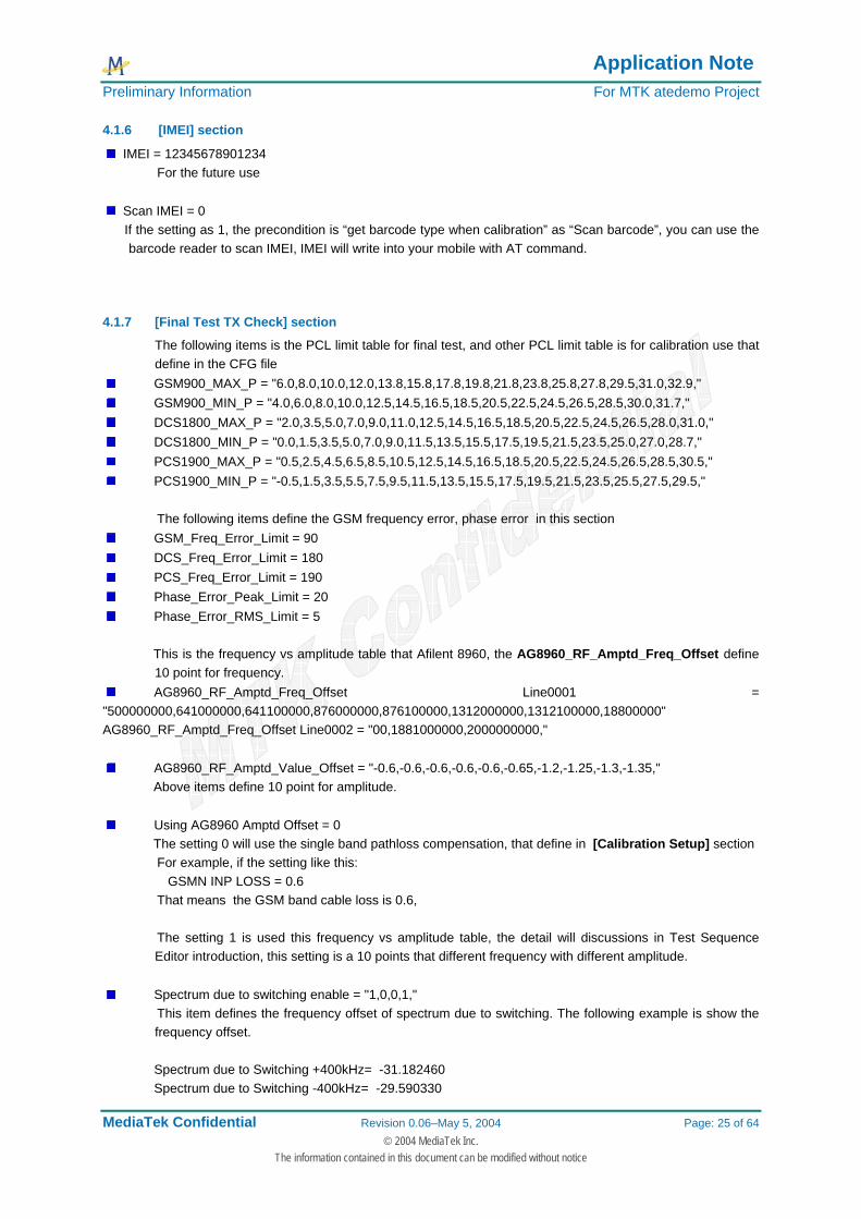
4.1.6 [IMEI] section
IMEI = 12345678901234 For the future use
Scan IMEI = 0 If the setting as 1, the precondition is “get barcode type when calibration” as “Scan barcode”, you can use the
barcode reader to scan IMEI, IMEI will write into your mobile with AT command.
4.1.7 [Final Test TX Check] section
The following items is the PCL limit table for final test, and other PCL limit table is for calibration use that define in the CFG file
GSM900_MAX_P = "6.0,8.0,10.0,12.0,13.8,15.8,17.8,19.8,21.8,23.8,25.8,27.8,29.5,31.0,32.9," GSM900_MIN_P = "4.0,6.0,8.0,10.0,12.5,14.5,16.5,18.5,20.5,22.5,24.5,26.5,28.5,30.0,31.7," DCS1800_MAX_P = "2.0,3.5,5.0,7.0,9.0,11.0,12.5,14.5,16.5,18.5,20.5,22.5,24.5,26.5,28.0,31.0," DCS1800_MIN_P = "0.0,1.5,3.5,5.0,7.0,9.0,11.5,13.5,15.5,17.5,19.5,21.5,23.5,25.0,27.0,28.7," PCS1900_MAX_P = "0.5,2.5,4.5,6.5,8.5,10.5,12.5,14.5,16.5,18.5,20.5,22.5,24.5,26.5,28.5,30.5," PCS1900_MIN_P = "-0.5,1.5,3.5,5.5,7.5,9.5,11.5,13.5,15.5,17.5,19.5,21.5,23.5,25.5,27.5,29.5,"
The following items define the GSM frequency error, phase error in this section
GSM_Freq_Error_Limit = 90 DCS_Freq_Error_Limit = 180 PCS_Freq_Error_Limit = 190 Phase_Error_Peak_Limit = 20 Phase_Error_RMS_Limit = 5
This is the frequency vs amplitude table that Afilent 8960, the AG8960_RF_Amptd_Freq_Offset define
10 point for frequency. AG8960_RF_Amptd_Freq_Offset Line0001 =
"500000000,641000000,641100000,876000000,876100000,1312000000,1312100000,18800000" AG8960_RF_Amptd_Freq_Offset Line0002 = "00,1881000000,2000000000,"
AG8960_RF_Amptd_Value_Offset = "-0.6,-0.6,-0.6,-0.6,-0.6,-0.65,-1.2,-1.25,-1.3,-1.35," Above items define 10 point for amplitude.
Using AG8960 Amptd Offset = 0 The setting 0 will use the single band pathloss compensation, that define in [Calibration Setup] section For example, if the setting like this:
GSMN INP LOSS = 0.6 That means the GSM band cable loss is 0.6, The setting 1 is used this frequency vs amplitude table, the detail will discussions in Test Sequence
Editor introduction, this setting is a 10 points that different frequency with different amplitude.
Spectrum due to switching enable = "1,0,0,1," This item defines the frequency offset of spectrum due to switching. The following example is show the
frequency offset. Spectrum due to Switching +400kHz= -31.182460 Spectrum due to Switching -400kHz= -29.590330

Application Note Preliminary Information For MTK atedemo Project
MediaTek Confidential Revision 0.06–May 5, 2004 Page: 26 of 64 © 2004 MediaTek Inc.
The information contained in this document can be modified without notice
Spectrum due to Switching +600kHz= -35.207820 Spectrum due to Switching -600kHz= -32.279390 Spectrum due to Switching +1.2MkHz= -34.092160 Spectrum due to Switching -1.2MkHz= -38.503780 Spectrum due to Switching +1.8MHz= -43.583010 Spectrum due to Switching -1.8MHz= -46.116880 If your define is “1,0,0,1,”, that means to do the +/- 400k and +/-1.8M frequency offset measurement.
Spectrum due to modulation enable = "0,0,0,1,0,0,0,0,0,0,1," This item defines the frequency offset of spectrum due to modulation. The following example is show the
frequency offset. Spectrum due to Modulation +100kHz= -8.557312 Spectrum due to Modulation -100kHz= -8.777496 Spectrum due to Modulation +200kHz= -34.214780 Spectrum due to Modulation -200kHz= -34.015660 Spectrum due to Modulation +250kHz= -39.874850 Spectrum due to Modulation -250kHz= -38.849580 Spectrum due to Modulation +400kHz= -61.613100 Spectrum due to Modulation -400kHz= -62.010590 Spectrum due to Modulation +600kHz= -66.382050 Spectrum due to Modulation -600kHz= -66.253600 Spectrum due to Modulation +800kHz= -66.471500 Spectrum due to Modulation -800kHz= -67.809330 Spectrum due to Modulation +1MHz= -68.384120 Spectrum due to Modulation -1MHz= -68.194400 Spectrum due to Modulation +1.2MHz= -69.887570 Spectrum due to Modulation -1.2MHz= -71.136630 Spectrum due to Modulation +1.4MHz= -73.157710 Spectrum due to Modulation -1.4MkHz= -72.516720 Spectrum due to Modulation +1.6MHz= -74.163570 Spectrum due to Modulation -1.6MHz= -76.117770 Spectrum due to Modulation +1.8MHz= -76.022610 Spectrum due to Modulation -1.8MHz= -78.223210 If your define is "0,0,0,1,0,0,0,0,0,0,1,", that means to do the +/400k and +/-1.8M frequency offset
measurement. Spectrum due to switch limit = "-10.0,-10.0,-21.0,-21.0,-21.0,-21.0,-24.0,-24.0,"
Define the spectrum due to switching limit value.
Spectrum due to modulation limit Line0001 = "0.5,0.5,-30.0,-30.0,-33.0,-33.0,-55.0,-55.0,-60.0,-60.0,-60.0,-60.0,-60.0,-60.0,"
Spectrum due to modulation limit Line0002 = "-60.0,-60.0,-60.0,-60.0,-60.0,-60.0,-60.0,-60.0," Define the spectrum due to modulation limit value.
4.1.8 [Barcode] section
Barcode = "S4716A0007 00"
Define the start value of Barcode, If your setting is “0001”, and your setting is Auto Barcode as 1, the test report will add barcode step automatically, but if your setting is Auto Barcode as 0, when do the calibration

Application Note Preliminary Information For MTK atedemo Project
MediaTek Confidential Revision 0.06–May 5, 2004 Page: 27 of 64 © 2004 MediaTek Inc.
The information contained in this document can be modified without notice
test, the barcode will read from target and write to the target NVRAM with calibration test status after calibration test.
Barcode Step = 1
No function define
Barcode Limit = "MT012345678901234569" This function is filter the unwanted barcode value, you can use this to check barcode station have been
write barcode or not
4.1.9 [Report Option] section
Part Number = "MTK_6205B" Batch = "02" Revision = "W04.24" Serial Number = "000001"
These items information will copy to the test report, if your setting is Auto Barcode, the Batch name will add into filename,
4.1.10 [Error Code] section
The following items define the call setup error status, such as if your target can’t location update success, or make a call fail, even when call drop, the following error code will show on the Test Information and Display Error Code of ATE program user interface.
Lacation update Fail = 101 MT Call Fail = 102 Call Drop = 103
The following items define the final test status
Average Burst Power Fail = 104 Peak Burst Power Fail = 105 PVT Match Fail = 106 Timing Error Fail = 107 Phase Error Peak Fail = 108 Phase Error RMS Fail = 109 Frequency Error Fail = 110 Spectrum due to Modulation Fail = 111 Spectrum due to Switching Fail = 112 Rx Quality Fail = 113 Rx Level Fail = 114 BER Fail = 115
The following items define the META DLL error code.
METAAPP_GET_AVAILABLE_HANDLE_FAIL = 201 METAAPP_OPEN_UART_FAIL = 202 METAAPP_CLOSE_UART_FAIL = 203 METAAPP_BOOT_FAIL = 204 METAAPP_BOOT_STOP_FAIL = 205 METAAPP_INIT_FAIL = 206 METAAPP_WAIT_FOR_TARGET_READY_FAIL = 207 METAAPP_COMM_SET_BAUD_RATE_FAIL = 208

Application Note Preliminary Information For MTK atedemo Project
MediaTek Confidential Revision 0.06–May 5, 2004 Page: 28 of 64 © 2004 MediaTek Inc.
The information contained in this document can be modified without notice
METAAPP_COMM_START_FAIL = 209 METAAPP_COMM_STOP_FAIL = 210 METAAPP_CONNECT_WITH_TARGET_FAIL = 211 METAAPP_DISCONNECT_WITH_TARGET_FAIL = 212 METAAPP_RF_SELECT_BAND_FAIL = 213 METAAPP_RF_SELECT_BAND_CNF_FAIL = 214 METAAPP_RF_AFC_MEASURE_FAIL = 215 METAAPP_RF_AFC_MEASURE_CNF_FAIL = 216 METAAPP_RF_AFC_SET_DAC_VALUE_FAIL = 217 METAAPP_RF_AFC_SET_DAC_VALUE_CNF_FAIL = 218 METAAPP_RF_PM_FAIL = 219 METAAPP_RF_NB_TX_FAIL = 220 METAAPP_RF_NB_TX_CNF_FAIL = 221 METAAPP_RF_SET_APC_LEVEL_DAC_FAIL = 222 METAAPP_RF_SET_APC_LEVEL_DAC_CNF_FAIL = 223 METAAPP_RF_STOP_FAIL = 224 METAAPP_RF_STOP_CNF_FAIL = 225 METAAPP_NVRAM_INIT_FAIL = 226 METAAPP_NVRAM_AFC_SLOPE_INVALID_FAIL = 227 METAAPP_NVRAM_AGC_PATHLOSS_LEN_FAIL = 228 METAAPP_NVRAM_GET_REC_LEN_FAIL = 229 METAAPP_NVRAM_GET_RAMPTABLE_LEN_FAIL = 230 METAAPP_NVRAM_COMPOSE_AGC_PATHLOSS_FAIL = 231 METAAPP_NVRAM_DECOMPOSE_AGC_PATHLOSS_FAIL = 232 METAAPP_NVRAM_COMPOSE_RAMPTABLE_FAIL = 233 METAAPP_NVRAM_DECOMPOSE_RAMPTABLE_FAIL = 234 METAAPP_NVRAM_SET_REC_FIELD_VALUE_FAIL = 235 METAAPP_NVRAM_GET_REC_FIELD_VALUE_FAIL = 236 METAAPP_NVRAM_COMPOSE_ADC_CAL_TABLE_FAIL = 237 METAAPP_NVRAM_DECOMPOSE_ADC_CAL_TABLE_FAIL = 238 METAAPP_NVRAM_COMPOSE_BARCODE_FAIL = 239 METAAPP_NVRAM_DECOMPOSE_BARCODE_FAIL = 240 METAAPP_NVRAM_COMPOSE_IMEI_FAIL = 241 METAAPP_NVRAM_DECOMPOSE_IMEI_FAIL = 242 METAAPP_NVRAM_WRITE_FAIL = 243 METAAPP_NVRAM_WRITE_CNF_FAIL = 244 METAAPP_NVRAM_READ_FAIL = 245 METAAPP_NVRAM_READ_CNF_FAIL = 246 METAAPP_FILE_READ_FAIL = 247 METAAPP_FILE_WRITE_FAIL = 248 METAAPP_IMEI_CALCULATE_CD_FAIL = 249 METAAPP_ADC_READ_FROM_NVRAM_CNF_FAIL = 250 METAAPP_ADC_MEASURE_FAIL = 251 METAAPP_ADC_MEASURE_CNF_FAIL = 252 METAAPP_TIMEOUT_FAIL = 253
The following items define the calibration test status.
AFC Calibration Fail = 254 Pathloss Calibration Fail = 255 APC Calibration Fail = 256

Application Note Preliminary Information For MTK atedemo Project
MediaTek Confidential Revision 0.06–May 5, 2004 Page: 29 of 64 © 2004 MediaTek Inc.
The information contained in this document can be modified without notice
ADC Calibration Fail = 257 Above the error code of these items , user can define the core name by their self,
4.1.11 [GSM xxx] section
This section define the test channel, like the following example, this case define one GSM test channel and one DCS test channel, if you want to increase a GSM test channel, you can add a new [GSM xx] section, xx means that you can define any thing depend on you, but “GSM “ is the strand define, ATE program will scan “GSM “, if scan one “GSM “, the program will do GSM test channel, for the DCS test is the same way, you can add a section “[DCS xx]”, the program will know to do the DCS test. Note: section name must be like : “GSM” + empty space (“GSM “), not “GSM” or “GSMxx”. [GSM 1] Active = 1 TCH = 3 -------------------------- Define TCH channel PCL = 5 -------------------------- Define PCL level Output Loss = 1.6 -------------------------- Define cable loss when use the wireless test function
or system calibration Input Loss = 0.3 Average Burst Power = 1 -------------------------- enable average power measurement Peak Burst Power = 1 -------------------------- enable peak power measurement PVT Match = 1 -------------------------- enable power vs time match or not Timing Error = 1 -------------------------- enable timing advance measurement Phase Error Peak = 1 -------------------------- enable phase error peak measurement Phase Error RMS = 1 -------------------------- enable phase error RMS measurement Frequency Error = 1 -------------------------- enable frequency error measurement Spectrum Modulation = 1 -------------------------- enable spectrum due to modulation measurement Spectrum Switch = 1 -------------------------- enable spectrum due to switching measurement Rx Quality = 1 -------------------------- enable RX quality measurement RX Level = 1 -------------------------- enable RX level measurement RFER = 0 -------------------------- enable RFER measurement BBB = 1 -------------------------- enable BBB measurement Gold Sample Average Power = 32.2 -------------------------- system calibration will reference this value to set
the input loss Gold Sample Rx Level = 29 -------------------------- system calibration will reference this value to set The output loss BER measurement level = -104 -------------------------- BER measurement level BS TCH level = -77 -------------------------- Define the RX level measurement level RX Level Max Limit = 35 -------------------------- Define the RX level max limit value RX Level Min Limit = 27 -------------------------- Define the RX level min limit value NOTE: Above items work precondition is “Default testing items” as 0, ATE Tool will reference this setting to do the test. [DCS 1] Active = 1 TCH = 62 PCL = 10
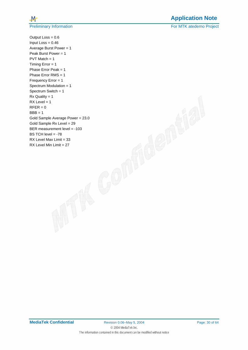
Application Note Preliminary Information For MTK atedemo Project
MediaTek Confidential Revision 0.06–May 5, 2004 Page: 30 of 64 © 2004 MediaTek Inc.
The information contained in this document can be modified without notice
Output Loss = 0.6 Input Loss = 0.46 Average Burst Power = 1 Peak Burst Power = 1 PVT Match = 1 Timing Error = 1 Phase Error Peak = 1 Phase Error RMS = 1 Frequency Error = 1 Spectrum Modulation = 1 Spectrum Switch = 1 Rx Quality = 1 RX Level = 1 RFER = 0 BBB = 1 Gold Sample Average Power = 23.0 Gold Sample Rx Level = 29 BER measurement level = -103 BS TCH level = -78 RX Level Max Limit = 33 RX Level Min Limit = 27

Application Note Preliminary Information For MTK atedemo Project
MediaTek Confidential Revision 0.06–May 5, 2004 Page: 31 of 64 © 2004 MediaTek Inc.
The information contained in this document can be modified without notice
4.2 ATE user interface introduction The following introduction is main test system display panel, the design concept is for easy to use, because this program is used for production line test, not R&D, so we need a simple panel, the important items of this panel, as you can see the figure this item such as: error code display, test item dynamic display, big screen Pass or Fail, and one button solution, test progress bar, view test report button, logging into excel auto or manual, terminate button, select test mode and initial, barcode display and test information, these are the important feature to the production line test.
Figure 9 Main Test Panel
Application Note Preliminary Information For MTK atedemo Project
MediaTek Confidential Revision 0.06–May 5, 2004 Page: 32 of 64 © 2004 MediaTek Inc.
The information contained in this document can be modified without notice
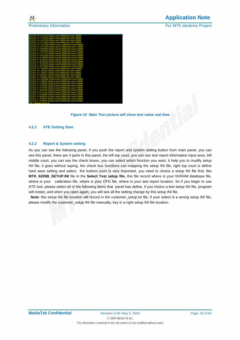
Figure 10 Main Test picture will show test value real time
4.2.1 ATE Getting Start
4.2.2 Report & System setting
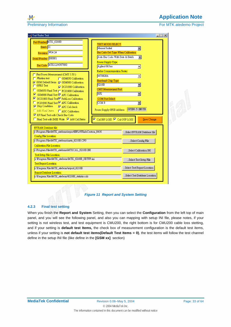
As you can see the following panel, if you push the report and system setting button from main panel, you can see this panel, there are 4 parts in this panel, the left top court, you can see test report information input area, left middle court, you can see the check boxes, you can select which function you want, it help you to modify setup INI file, it goes without saying, the check box functions can mapping the setup INI file, right top court is define hard ware setting and select, the bottom court is very important, you need to choice a setup INI file first, like MTK_6205B_SETUP.INI file in the Select Test setup file, this file record where is your NVRAM database file, where is your calibration file, where is your CFG file, where is your test report location, So if you begin to use ATE tool, please select all of the following items that panel has define, if you choice a test setup INI file, program will restart, and when you open again, you will see all the setting change by this setup INI file. Note: this setup INI file location will record in the customer_setup.txt file, if your select is a wrong setup INI file, please modify the customer_setup INI file manually, key in a right setup INI file location.
Application Note Preliminary Information For MTK atedemo Project
MediaTek Confidential Revision 0.06–May 5, 2004 Page: 33 of 64 © 2004 MediaTek Inc.
The information contained in this document can be modified without notice
Figure 11 Report and System Setting
4.2.3 Final test setting
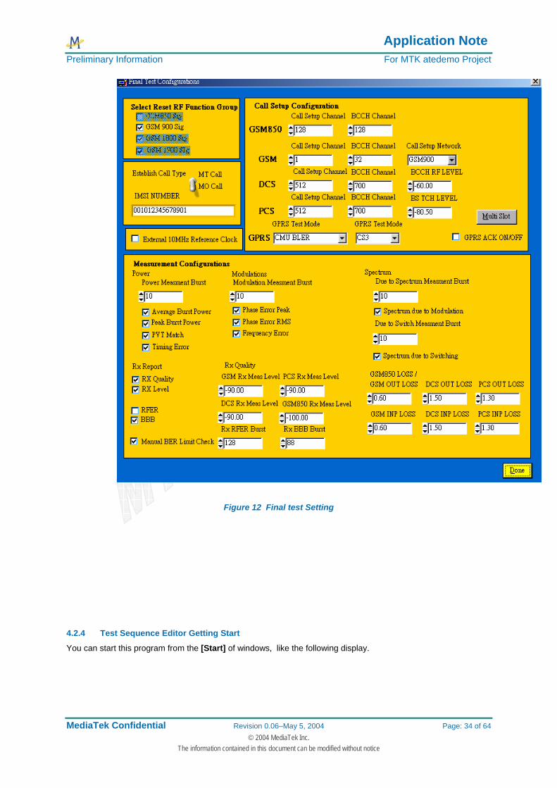
When you finish the Report and System Setting, then you can select the Configuration from the left top of main panel, and you will see the following panel, and also you can mapping with setup INI file, please notes, if your setting is not wireless test, and test equipment is CMU200, the right bottom is for CMU200 cable loss stetting, and if your setting is default test Items, the check box of measurement configuration is the default test items, unless if your setting is not default test items(Default Test Items = 0), the test items will follow the test channel define in the setup INI file (like define in the [GSM xx] section)
Application Note Preliminary Information For MTK atedemo Project
MediaTek Confidential Revision 0.06–May 5, 2004 Page: 34 of 64 © 2004 MediaTek Inc.
The information contained in this document can be modified without notice
Figure 12 Final test Setting
4.2.4 Test Sequence Editor Getting Start
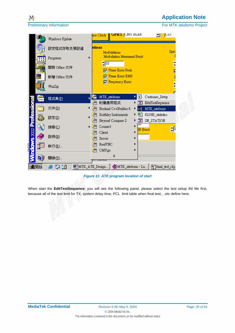
You can start this program from the [Start] of windows, like the following display.
Application Note Preliminary Information For MTK atedemo Project
MediaTek Confidential Revision 0.06–May 5, 2004 Page: 35 of 64 © 2004 MediaTek Inc.
The information contained in this document can be modified without notice
Figure 13 ATE program location of start
When start the EditTestSequence, you will see the following panel, please select the test setup INI file first, because all of the test limit for TX, system delay time, PCL limit table when final test,…etc define here.

Application Note Preliminary Information For MTK atedemo Project
MediaTek Confidential Revision 0.06–May 5, 2004 Page: 36 of 64 © 2004 MediaTek Inc.
The information contained in this document can be modified without notice
Figure 14 Configure Final test parameter panel.
Application Note Preliminary Information For MTK atedemo Project
MediaTek Confidential Revision 0.06–May 5, 2004 Page: 37 of 64 © 2004 MediaTek Inc.
The information contained in this document can be modified without notice
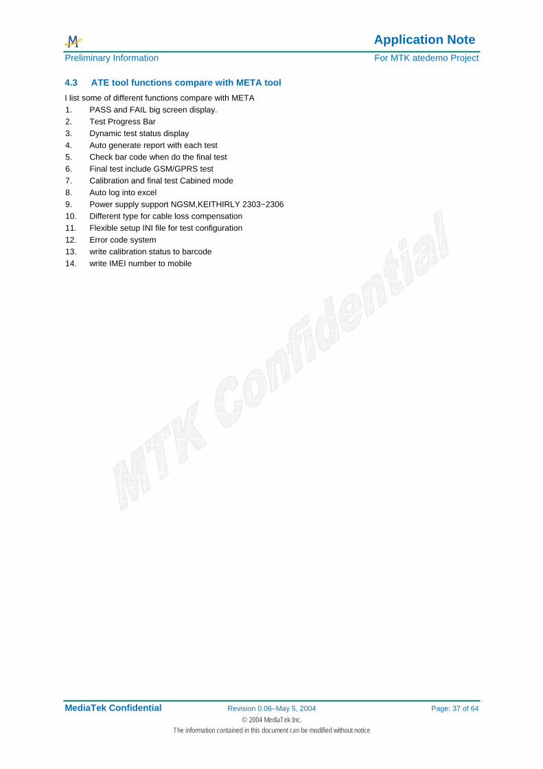
4.3 ATE tool functions compare with META tool I list some of different functions compare with META 1. PASS and FAIL big screen display. 2. Test Progress Bar 3. Dynamic test status display 4. Auto generate report with each test 5. Check bar code when do the final test 6. Final test include GSM/GPRS test 7. Calibration and final test Cabined mode 8. Auto log into excel 9. Power supply support NGSM,KEITHIRLY 2303~2306 10. Different type for cable loss compensation 11. Flexible setup INI file for test configuration 12. Error code system 13. write calibration status to barcode 14. write IMEI number to mobile
Application Note Preliminary Information For MTK atedemo Project
MediaTek Confidential Revision 0.06–May 5, 2004 Page: 38 of 64 © 2004 MediaTek Inc.
The information contained in this document can be modified without notice
4.4 Result and Test Report Format
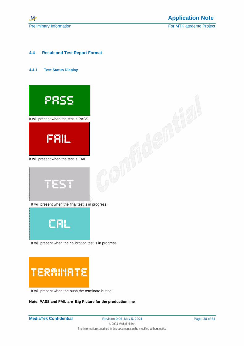
4.4.1 Test Status Display
It will present when the test is PASS
It will present when the test is FAIL
It will present when the final test is in progress
It will present when the calibration test is in progress
It will present when the push the terminate button Note: PASS and FAIL are Big Picture for the production line
Application Note Preliminary Information For MTK atedemo Project
MediaTek Confidential Revision 0.06–May 5, 2004 Page: 39 of 64 © 2004 MediaTek Inc.
The information contained in this document can be modified without notice
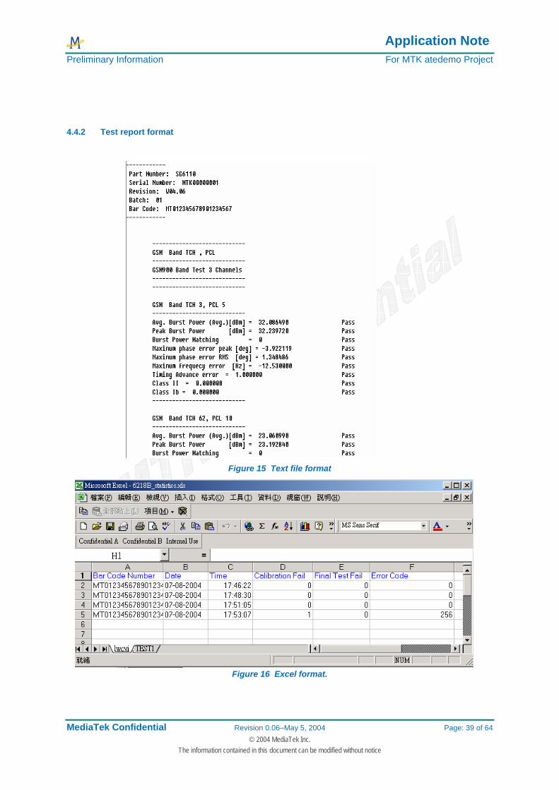
4.4.2 Test report format
Figure 15 Text file format
Figure 16 Excel format.
Application Note Preliminary Information For MTK atedemo Project
MediaTek Confidential Revision 0.06–May 5, 2004 Page: 40 of 64 © 2004 MediaTek Inc.
The information contained in this document can be modified without notice
5 GSM Testing Items for ATE tool
5.1 GSM Standard Testing Items (For R&S CMU200 example) The following items are GSM standard-testing items, the target must be enter into normal mode for signaling measurement.
5.1.1 Location update test
When do the location update, CMU200 BS will generate BCCH for communication with target, the target must be power on after SON, otherwise the location update will be fail.
Figure 17 R&S CMU200 Call Established Flow chart
NOTE: Please make sure that the target has test SIM card before test
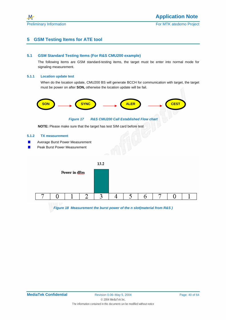
5.1.2 TX measurement
Average Burst Power Measurement Peak Burst Power Measurement
Figure 18 Measurement the burst power of the n slot(material from R&S )
SON SYNC ALER CEST
Application Note Preliminary Information For MTK atedemo Project
MediaTek Confidential Revision 0.06–May 5, 2004 Page: 41 of 64 © 2004 MediaTek Inc.
The information contained in this document can be modified without notice
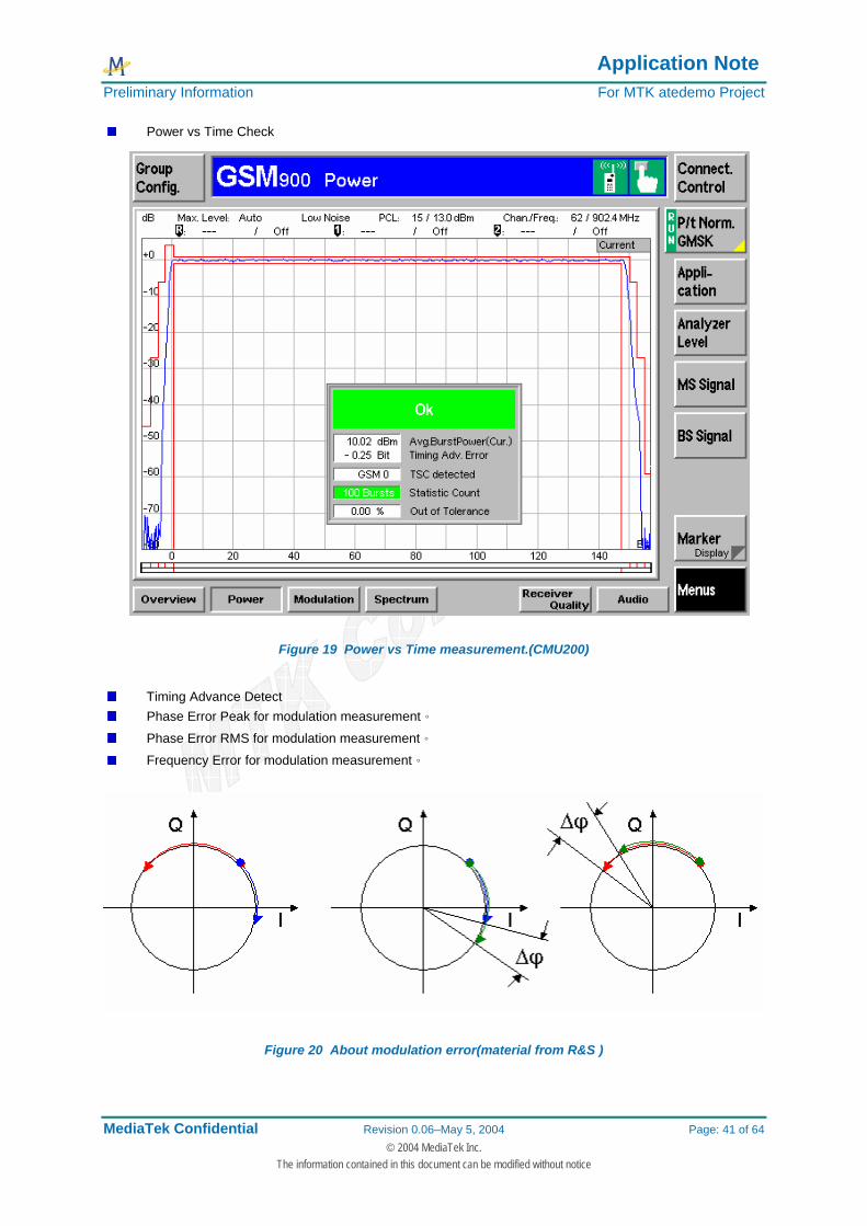
Power vs Time Check
Figure 19 Power vs Time measurement.(CMU200)
Timing Advance Detect Phase Error Peak for modulation measurement。
Phase Error RMS for modulation measurement。
Frequency Error for modulation measurement。
Figure 20 About modulation error(material from R&S )
Application Note Preliminary Information For MTK atedemo Project
MediaTek Confidential Revision 0.06–May 5, 2004 Page: 42 of 64 © 2004 MediaTek Inc.
The information contained in this document can be modified without notice
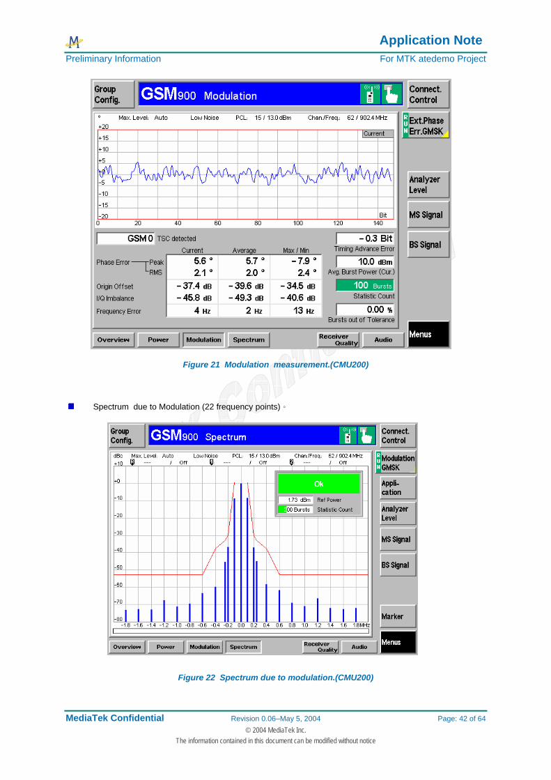
Figure 21 Modulation measurement.(CMU200)
Spectrum due to Modulation (22 frequency points)。
Figure 22 Spectrum due to modulation.(CMU200)
Application Note Preliminary Information For MTK atedemo Project
MediaTek Confidential Revision 0.06–May 5, 2004 Page: 43 of 64 © 2004 MediaTek Inc.
The information contained in this document can be modified without notice
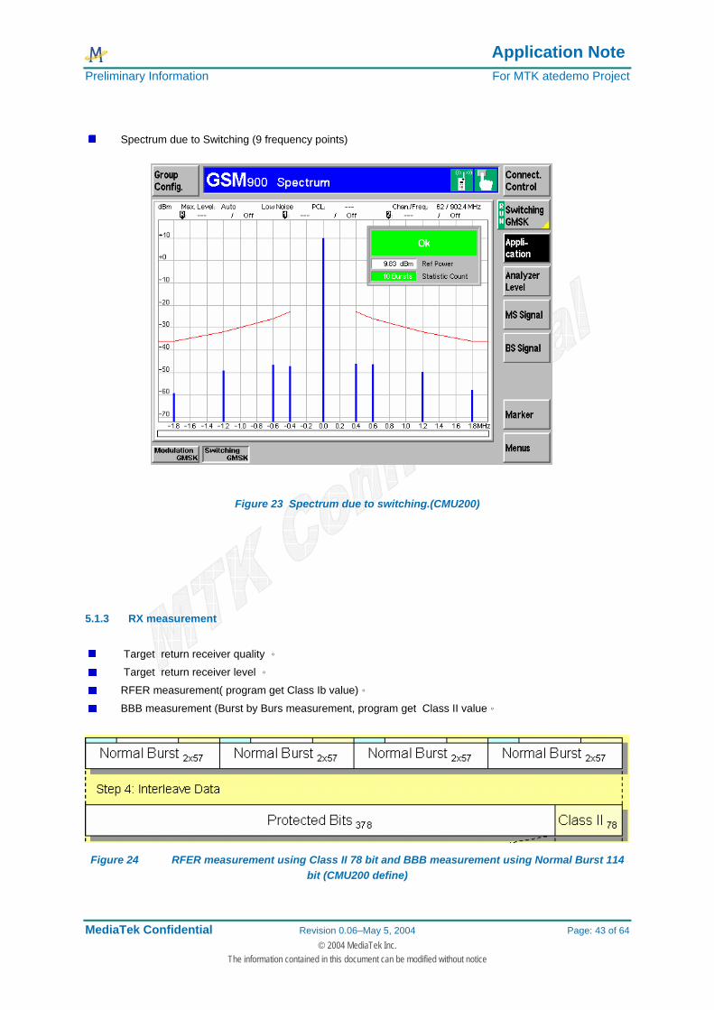
Spectrum due to Switching (9 frequency points)
Figure 23 Spectrum due to switching.(CMU200)
5.1.3 RX measurement
Target return receiver quality 。
Target return receiver level 。
RFER measurement( program get Class Ib value)。
BBB measurement (Burst by Burs measurement, program get Class II value。
Figure 24 RFER measurement using Class II 78 bit and BBB measurement using Normal Burst 114 bit (CMU200 define)
Application Note Preliminary Information For MTK atedemo Project
MediaTek Confidential Revision 0.06–May 5, 2004 Page: 44 of 64 © 2004 MediaTek Inc.
The information contained in this document can be modified without notice
6 Test Setting major constraints check list
This section is discussions about some import setting must be correct before your test, and will impact the manner in which the software is to be tested or implemented are noted here. First of all, please make sure the instrument status, ATE tool can control the following equipment:
Agilent 8960 with GSM only mode and GSM/GPRS mode CMU200 with version 3.10~3.52 Agilent 663x2 series power supply. R&S NGSM power supply Keithely 2303,2304,2306
NOTE: If program start fail , Please make sure that the TXT file is complete, please backup the setup file, CFG
file, customer_setup.txt file , customer_setup file will specify which path to find your setup INI file, If your PC system location is D, please change the setting in the customer setup file and setup INI file path location
Please notice the TEXT format, you muse be comply like following example, empty space is not allow: Right way: GSM850_WANTED_P = 5.5,7.5,9.5,11.5,13.5,15.5,17.5,19.5,21.5,23.5,25.5,27.5,29.5,31.5,32.7,
Wrong way: GSM850_WANTED_P = 5.5 ,7.5 ,9.5 ,11.5,13.5 ,15.5,17.5 ,19.5,21.5,23.5,25.5,27.5,29.5,31.5,32.7,
NOTE: If your test result PASS or FAIL judge is not correct, please make your limit value setting is correctly ,
TX Limit Check by Tester = 1 ,it means the result will judged by Setup INI file define, including PCL power
max limit or min limit, modulation limit, spectrum due to modulation limit, spectrum due to switch limit all
define in the setup INI file, But if your setting as 0, the result will judged by instrument define.
BER and RX Level limit is define depend on “Default testing items = 1 or 0 “, If the “Default testing items “ as 1, Limit define in the [Signalling Measurement] section, If the setting as 0 , limit define following [GSM xx] section
NOTE: there are two way to define the cable loss, one is define in the [Signalling Measurement] section or [Calibration Setup], another is define in the [Final Test TX Check] section, please make sure Using AG8960 Amptd Offset = 1 if your instrument is using agilent 8960 , but if your instrument is CMU200, please make sure “Wireless Test = 1” , the cable loss is define in the [GSM xx] sections
NOTE:Power supply control will follow ADC Calibration = 1 setting, if you do not select this, you should turn on power supply by yourself.
6.1 Final Test Constraints Note1: CMU200 or Agilent 8960 Initial fail problem
Please make sure that instruments are exist,GPIB cable is connected, and GPIB address is correct, Agilent 8960 GPIB address define in the CFG file, and CMU200 define in the setup INI file.。
Please make sure that the radiocommunication tester select is correct.。
Note2: Program start Lock situation If your setting(Test Mode = ) is not 0,please wait for instrument initialized, or you need to push the Initial Final Test button,
Note3: Target GSM connect fail problem Please enter into the Report & system button, and setting the cable loss, and IMSI number, make sure that the IMSI is comply whit you test SIM card number if your setting is using MT Call,
Application Note Preliminary Information For MTK atedemo Project
MediaTek Confidential Revision 0.06–May 5, 2004 Page: 45 of 64 © 2004 MediaTek Inc.
The information contained in this document can be modified without notice
Also need to check test SIM has put into the target.,or If your setting is MO Call, please make sure that your download can send AT command( you can try this with Hyper terminal).
Note4: Scan IMEI problem If the Scan IMEI setting as 1,and “get barcode type when calibration” as “Barcode scan” ,ATE will send AT Command to write IMEI number to target,please make sure the rs232 cable is correct
Note5: VIEW test report fail problem Test report location must be have the exist folder and right path.
Note6: If the measurement is fail, but ATE Tool show PASS problem Please make sure that the Stop Condition as selected or nit.
Note7: Final test always fail problem Please make sure that there have big capacitor in the test fixture, because if not, some mobile will
produce low battery shut down status
6.2 Calibration Test Constraints Note1: META Boot Fail or sync with target fail
Make sure the NVRAM database is right or not, and CFG file,calibration INI file is right or not., COM Port setting is very important, If your target still can not enter into META mode, Please make sure your target can work with META Tool
Note2: First calibration fail or control power supply fail problem Please make sure that the setting in the setup INI file,” Enter META Timer Delay= 2.0” ,you can do some modify this delay time for this problem
Note3: Agilent 8960 calibration fail in APC situation
If your Agilent 8960 as GSM mode only, please make sure that the AG8960 GSM as 1 Note4: Auto barcode problem
If Auto Barcode setting as 1,please make sure that the Barcode = "0001", If you select add calibration status, please note the char[60],char[61], It will put character into these buffer.
Note5: ADC Calibration fail problem
If ADC calibration as selected, the power supply is requirement and ATE will do the battery calibration. The battery channel define in the CFG file, please make sure the setting is correct or not
6.3 Combined Test Constraints Note1:Final test always fail problem
Please make sure that if ADC select or not, if the setting ADC Calibration = 1, power supply will control by ATE Tool, If the setting as 0, you should control by yourself, after calibration, you should power on mobile again
6.4 Other Test Constraints

Application Note Preliminary Information For MTK atedemo Project
MediaTek Confidential Revision 0.06–May 5, 2004 Page: 46 of 64 © 2004 MediaTek Inc.
The information contained in this document can be modified without notice
7 ATE Design Specification
This section provides an overview of the entire ATE design concept, and describes all data, architectural, interface and component level design for the ATE.
7.1 ATE software design introduction Note: This manual starts with the assumption that the reader is familiar with “National Instruments Labwindows CVI 7.0, If user need to get familiar with this platforms, please contact with National Instrument. To establish links between instrument and target, it is possible to use the original driver functions for CVI, For R&S CMU200; we load the function panel of rscmu200.fp、 rscmuk2g.fp, For R&S power supply, load the function panel of rsngsm.fp, For Agilent 8960, load the function panel age1960.fp, For Agilent power supply, load the hp663x2.fp. above all is the instrument control driver, and for the target, ATE project need to link brom.dll、META_DLL.dll、META_APP.dll to the communication with the target when to do the calibration test. This method has however certain advantages, for example: When a Agilent hp663x2 Power Supply must be set-up in a CVI source code, the following function provided by the Agilent, ATE project can call to the hp663x2.fp, then select the initialize function and you will see the following panel.
Figure 25 LabWindows/CVI function panel

Application Note Preliminary Information For MTK atedemo Project
MediaTek Confidential Revision 0.06–May 5, 2004 Page: 47 of 64 © 2004 MediaTek Inc.
The information contained in this document can be modified without notice
If the GPIB address of this instrument need to be changed, the 1’st parameter in the function must be modified as well, The GPIB_ADDR_PSU is “GPIB0::5::INSTR”, that means the GPIB address is 5,and if want to change the GPIB address to 6, just set the variable of GPIB_ADDR_PSU is “GPIB0::6::INSTR” in the mtk_adedemo_V1.c that is the main code of this project. Implementing ATE specifies a lot of settings in one “Setup.INI files” with text format. This allows easy modification with a text editor. So ATE program using the read and write INI method, you can see inifile.fp in the project for this application. Finally, the ATE project software design concept is base on easy to modify, complete function call… etc.
Application Note Preliminary Information For MTK atedemo Project
MediaTek Confidential Revision 0.06–May 5, 2004 Page: 48 of 64 © 2004 MediaTek Inc.
The information contained in this document can be modified without notice
7.2 ATE project structure
7.2.1 ATE source code structure
ATE tool can be separated with three part of test, including calibration test, final test, and combined mode test, So if you want to check the source code for each test mode, you can reference the MTK_atedemo.uir file directly and view the control callback by CVI. To do that and reference the following chart to understand the whole source code structure, I believe it is simple to understand the ATE source code structure. The red line is meaning of the loop test. Some important functions listed in the following examples: The following function is the very import function in the ATE source code
Function name: int CVICALLBACK RunSequence(int panel, int control, int event, void *callbackData, int eventData1, int eventData2) ;
This function is used to run the final test of the ATE program, you can see the check bar code function first,
and you can see the GSM_Autotest() function, GSM_Autotest()function is the used to test GSM standard with CMU200 and GSM_Autotest_AG() is used to test with Agilent 8960.
As you can see the function OutputResults(), this function is the report generate function, the program will
copy the test report by this function, and generate a text file when call to this function.
Function name: int CVICALLBACK Loop(int panel, int control, int event, void *callbackData, int eventData1, int eventData2) ;
This function is used to run the combined test of calibration and final test, you can see the power supply
control first, Calibration () function can do the whole calibration test, ATE program call this function to do the this test, and control the power supply after calibration,program let the target enter into normal mode, and then call to the GSM_Autotest_AG() or GSM_Autotest() to do the final test.
Function name: int CVICALLBACK RunCalSequence (int panel, int control, int event,
void *callbackData, int eventData1, int eventData2) This function is include calibration test sequence, and the following functions are the major functions in calibration: 1. Cal_wrt_to_flash (); 2. AFC_Calibration (); 3. Path_Loss_Calibration (); 4. APC_Calibration (); 5. APC_Cal_PCL_Check(); 6. ADC_CAL();
Above these functions are in the calibration purpose, the detail will explain in the following sections.
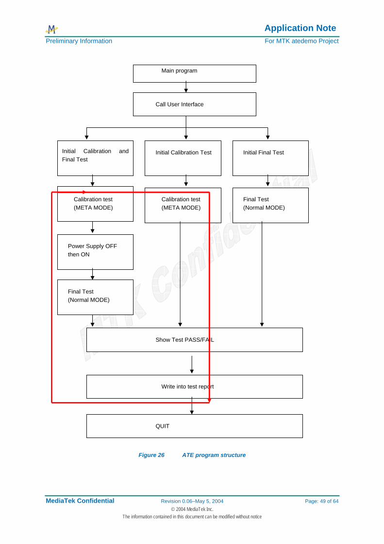
Figure 24 is the chart of ATE main function structure, It goes without saying that the you can see the three way of test.
Application Note Preliminary Information For MTK atedemo Project
MediaTek Confidential Revision 0.06–May 5, 2004 Page: 49 of 64 © 2004 MediaTek Inc.
The information contained in this document can be modified without notice
Figure 26 ATE program structure
Initial Calibration and Final Test
Main program
Call User Interface
Initial Calibration Test Initial Final Test
Calibration test (META MODE)
Final Test (Normal MODE)
Calibration test (META MODE)
Final Test (Normal MODE)
Power Supply OFF then ON
Show Test PASS/FAIL
Write into test report
QUIT

Application Note Preliminary Information For MTK atedemo Project
MediaTek Confidential Revision 0.06–May 5, 2004 Page: 50 of 64 © 2004 MediaTek Inc.
The information contained in this document can be modified without notice
7.2.2 Calibration test source code structure
Please take a look at the following chart, as you can see, there are three dll files to do the communication with target, ATE main program call these dll functions to control the target to enter into META mode. When do the calibration test, it must be initial the NVRAM first, and this is at the first time to start the program. So it needs the NVRAM database file that the right binary file for your target.
When you do the calibration test, you need to input the target default parameters, the calibration ini is a text file that is define the target default parameters, so we need to let the program read from this file before calibration test, and the CFG file define that which channel you want to calibration, which is the start value of the calibration, What is the limit value maximum and minimum, CFG file define the configure parameters when you to do the calibration. Figure 25 tell you how to do the calibration test in your program, you must be call these three dll to do the calibration test, and also need to prepare the NVRAM database file 、calibration INI file, CFG file before the calibration test.
Figure 27 Calibration software structure
As you can see the example for CFG file and calibration INI file, As you can see the following content of INI file, this is for APC calibration example, APC default DAC value define in the calibration INI file, you can see the section of [GSM900 level, ramp]. You can see the TX PCL DAC value from PCL5 to PCL19, dc offset, power ramp, The value in this file is the well define value, So must of our customer just need to read from this file before calibration test.
Calibration test
META_APP.dll
META.dll
Brom.dll
Target
Calibration INI file
Meta_6205B/meta_6218B CFG file
NVRAM Database file
Agilent 8960 /CMU200 & Power Supply control program code
Application Note Preliminary Information For MTK atedemo Project
MediaTek Confidential Revision 0.06–May 5, 2004 Page: 51 of 64 © 2004 MediaTek Inc.
The information contained in this document can be modified without notice
when you to do the calibration test, your wanted power define in the CFG file, the maximum and Minimum limit also in this file, our APC calibration is used middle channel calibration, So if you want to calibration 5dBm at PCL5, limit check is define in the CFG file, and when you to do the adjust power, you can see the recursive time, after APC calibration, you will check each PCL limit, is also define here too. You can reference the following text content. The following items are defined in the calibration INI file [GSM900 level, ramp] APC dc offset=115 TX power level=68,78,90,104,123,145,168,197,238,282,340,420,500,600,710,710 profile 0 ramp up=0,0,0,0,0,0,2,4,8,26,65,143,228,255,255,255 profile 0 ramp down=255,255,239,197,138,78,32,10,0,0,0,0,0,0,0,0 profile 1 ramp up=0,0,0,0,0,0,2,4,8,26,65,143,225,255,255,255 The following items are defined in the CFG file [C0 for each Bank] arfcn_C0_GSM = 70 [TX PCL table] GSM900_CAL_PCL = 17,12,5, GSM900_PCL = 19,18,17,16,15,14,13,12,11,10,9,8,7,6,5, GSM900_CHECK_PCL = 19,18,17,16,15,14,13,12,11,10,9,8,7,6,5, GSM900_MAX_P = 6,8,10,12,13.8,15.8,17.8,19.8,21.8,23.8,25.8,27.8,29.5,31,32.8, GSM900_WANTED_P = 5,7,9,11,13,15,17,19,21,23,25,27,29,30.5,32.2, GSM900_MIN_P = 4,6,8,10,12.5,14.5,16.5,18.5,20.5,22.5,24.5,26.5,28.5,30,31.7 GSM900_C = 3,3,3,3,4,4,6,6,8,8,12,12,15,15,35,40, GSM900_CORRECTION = -0.3,0,0.2,0.3,0.4,0.2,0.1,0,0,0,0,0,0,0,0, Recursive Times=10 APC Delta=0.1

Application Note Preliminary Information For MTK atedemo Project
MediaTek Confidential Revision 0.06–May 5, 2004 Page: 52 of 64 © 2004 MediaTek Inc.
The information contained in this document can be modified without notice
7.2.3 Final source code structure
For the final test, all of the important parameters are defined in the setup INI file, like the following example mention about. the program will read setup INI file when you to do the final test, setup INI file define the System Setting, Call Setup Configuration, Final Test TX Check, Barcode, Report Option, Error Code, and test sequence depend on your define. For control instrument that as you can see in instrument function panel file, full control functions in the function panel file of CVI, this is a very good advantage for feature to add test functions.
Figure 28 Final test software structure
You can see this chart (figure 26), you can see the test sequence engine that has to do the final test, and which channel need to be test is defined in the setup INI file, you can see the following example text to understand that just add a test section, and you can increase a test channel, [GSM 1] Active = 1 TCH = 3 PCL = 5 Output Loss = 7.5 Input Loss = 7.5 Average Burst Power = 1 Peak Burst Power = 1 PVT Match = 1 Timing Error = 1 Phase Error Peak = 1 Phase Error RMS = 1 Frequency Error = 1 Spectrum Modulation = 0 Spectrum Switch = 0 Rx Quality = 0 RX Level = 0 RFER = 0 BBB = 1 [GSM 2] ……..
Final Test Start
SETUP INI file Test Sequence Engine
Generator test report
Login to Excel
Application Note Preliminary Information For MTK atedemo Project
MediaTek Confidential Revision 0.06–May 5, 2004 Page: 53 of 64 © 2004 MediaTek Inc.
The information contained in this document can be modified without notice
……… Let us take a look at see the section of [Signalling Measurement], you can define the power measurement like this : Average Burst Power = 1 It means that your define for the average burst power measurement item, It means that you can define the measurement burst for statistic Power Measment Burst = 10 The following section is error code define [Error Code] Lacation update Fail = 101 MT Call Fail = 102 Call Drop = 103 It goes without saying that you can define the error code by yourself About the how to implement in the code, you can use the following functions to get value from setup INI file: Ini_GetPointerToRawString (g_myInifile,"Error Code","METAAPP_GET_AVAILABLE_HANDLE_FAIL", &test_err_code); strcpy(META_ErrCode_Msg,"METAAPP_GET_AVAILABLE_HANDLE_FAIL=>"); strcat(META_ErrCode_Msg,test_err_code); You can use the Ini_GetPointerToRawString function of CVI that you can reference in the inifile.fp, this function can read a raw string from the specify file, you can specify the section name and the item, and then you will get the value.

Application Note Preliminary Information For MTK atedemo Project
MediaTek Confidential Revision 0.06–May 5, 2004 Page: 54 of 64 © 2004 MediaTek Inc.
The information contained in this document can be modified without notice
7.2.4 INI file structure
Please take a look at this chart, as you can see that you can choice by the different way, custom setup text file define what is your setup ini file, and your setup file will tell the system where is the NVRAM database, where is your calibration CFG file, where is your calibration ini file, where is the test report location, it goes without saying that you can define your application for different station, different model, just change different setup ini file, the test system will prepare for different application test. This way provides very flexible application, text file that you can modify easy with text editor, You can see a simple example in Figure 25 ,
Figure 29 Final test software structure
ATE tool program Customer_Setup.txt Setup_QA.ini
Application 1
Setup_BT.ini Application 2
NVRAM Database1 6205B
NVRAM Database2 6218B
Calibration_ 6205_default.ini
Calibration_6218_default.ini
Meta_6205B.CFG
Meta_6218B.CFG
MTK12345.txt
20040803010001.txt
6205B.xsl

Application Note Preliminary Information For MTK atedemo Project
MediaTek Confidential Revision 0.06–May 5, 2004 Page: 55 of 64 © 2004 MediaTek Inc.
The information contained in this document can be modified without notice
7.3 Calibration Function Call This chapter introduces the basic concepts of calibration interactions using the META_APP DLL.. It also describes calibration procedure, the important structures of ATE, and the useful functions.
7.3.1 META initial function code
When we need to do the calibration test, we need to use the following functions from META_APP.dll to control target. This function is used to initial the NVRAM. We must do it first For example: The following function is define a variable of NVRAM location char tempFileNameDB[MAX_PATHNAME_LEN]
= "C:\\ProgramFiles\\MTK_atedemo\\report\\ BPLGUInfoCustom"; you can see that we just need to input the NVRAM database location in the METAAPP_NVRAM_Init function, and if meta_app_result is zero, that we can know the NVRAM initial is OK. meta_app_result = METAAPP_NVRAM_Init(tempFileNameDB );
7.3.2 AFC calibration source code structure
For AFC calibration stage, we need to use the following functions from META_APP.dll to control the target. meta_app_result=METAAPP_getAFCSlopeAndOffset(meta_handle,band,arfcn, (short)afc_dac1,
(short)afc_dac2,40,(short)afc_num, 5000, &AfcSlopeOffsetValid,&us_Default_value, &f_Slope);
meta_app_result=METAAPP_writeAFCtoNVRAM(meta_handle,us_Default_value, f_Slope, 5000 );
meta_app_result=METAAPP_SetAfcDacValue(meta_handle, us_Default_value, 5000);

Application Note Preliminary Information For MTK atedemo Project
MediaTek Confidential Revision 0.06–May 5, 2004 Page: 56 of 64 © 2004 MediaTek Inc.
The information contained in this document can be modified without notice
7.3.3 Pathloss calibration source code structure
The following chart is show the path loss calibration loop, we need to get the DSP returned power and calculate the compensation of loss
AgcPathLoss.agcPathLoss[2][i].gain_offset= ((dl_pwr-(p_power/8.0))*8.0)+ AgcPathLoss.agcPathLoss[2][i].gain_offset;
Figure 30 Pathloss calibration structure
For pathloss calibration stage, we need to use the following functions from META_APP.dll to control the target. meta_app_result= METAAPP_readAgcFromFile(meta_handle, tempFileNameCal,&AgcPathLoss); meta_app_result= METAAPP_writeAgcToNVRAM(meta_handle, &AgcPathLoss, 5000);
meta_app_result=METAAPP_PM(meta_handle,band, dcs_rx_loss_tch[i], num_of_meas, gain, num_of_fram, 5000,&p_power,&pm_dev, &usedgain);
meta_app_result= METAAPP_writeAgcToNVRAM(meta_handle, &AgcPathLoss, 5000);
Set GSM TCH and output power
DSP measurement Power
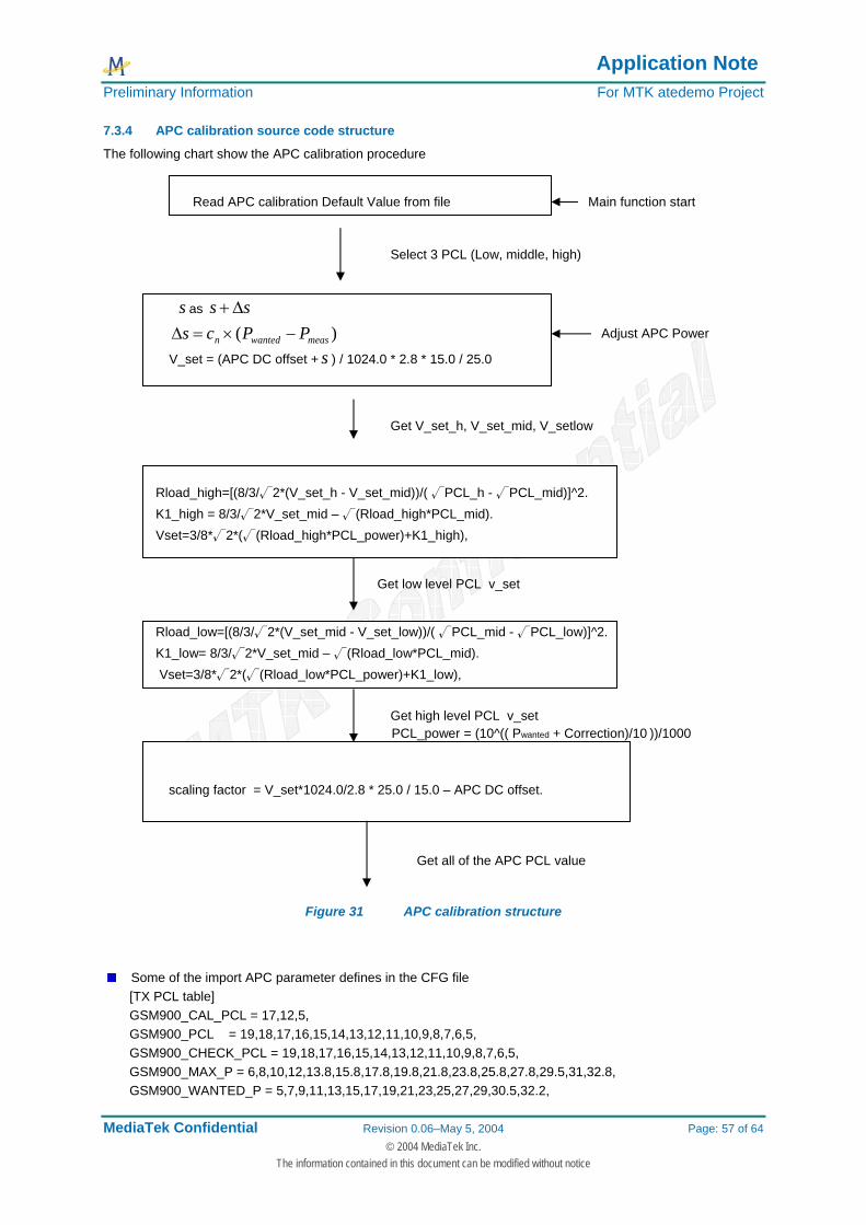
Application Note Preliminary Information For MTK atedemo Project
MediaTek Confidential Revision 0.06–May 5, 2004 Page: 57 of 64 © 2004 MediaTek Inc.
The information contained in this document can be modified without notice
7.3.4 APC calibration source code structure
The following chart show the APC calibration procedure
s as ss Δ+
)( measwantedn PPcs −×=Δ
V_set = (APC DC offset + s ) / 1024.0 * 2.8 * 15.0 / 25.0
Rload_high=[(8/3/√2*(V_set_h - V_set_mid))/( √PCL_h - √PCL_mid)]^2. K1_high = 8/3/√2*V_set_mid – √(Rload_high*PCL_mid). Vset=3/8*√2*(√(Rload_high*PCL_power)+K1_high),
Rload_low=[(8/3/√2*(V_set_mid - V_set_low))/( √PCL_mid - √PCL_low)]^2. K1_low= 8/3/√2*V_set_mid – √(Rload_low*PCL_mid). Vset=3/8*√2*(√(Rload_low*PCL_power)+K1_low),
PCL_power = (10^(( Pwanted + Correction)/10 ))/1000
scaling factor = V_set*1024.0/2.8 * 25.0 / 15.0 – APC DC offset.
Figure 31 APC calibration structure
Some of the import APC parameter defines in the CFG file [TX PCL table] GSM900_CAL_PCL = 17,12,5, GSM900_PCL = 19,18,17,16,15,14,13,12,11,10,9,8,7,6,5, GSM900_CHECK_PCL = 19,18,17,16,15,14,13,12,11,10,9,8,7,6,5, GSM900_MAX_P = 6,8,10,12,13.8,15.8,17.8,19.8,21.8,23.8,25.8,27.8,29.5,31,32.8, GSM900_WANTED_P = 5,7,9,11,13,15,17,19,21,23,25,27,29,30.5,32.2,
Read APC calibration Default Value from file Main function start
Select 3 PCL (Low, middle, high)
Adjust APC Power
Get V_set_h, V_set_mid, V_setlow
Get low level PCL v_set
Get high level PCL v_set
Get all of the APC PCL value

Application Note Preliminary Information For MTK atedemo Project
MediaTek Confidential Revision 0.06–May 5, 2004 Page: 58 of 64 © 2004 MediaTek Inc.
The information contained in this document can be modified without notice
GSM900_MIN_P = 4,6,8,10,12.5,14.5,16.5,18.5,20.5,22.5,24.5,26.5,28.5,30,31.7 GSM900_C = 3,3,3,3,4,4,6,6,8,8,12,12,15,15,35,40, GSM900_CORRECTION = -0.3,0,0.2,0.3,0.4,0.2,0.1,0,0,0,0,0,0,0,0,
TSC=5 Recursive Times=10 APC Delta=0.1
Some of the imports APC parameter defines in the INI file [GSM900 level, ramp] APC dc offset=115 TX power level=68,78,90,104,123,145,168,197,238,282,340,420,500,600,710,710
For this stage, we need to use the following functions from META_APP.dll to control target.
meta_app_result=METAAPP_RF_NB_TX(meta_handle,0,gsm_co_ch,tsc, PCL, 200, us_Default_value, 5000); Use this function to enable a TX PCL power meta_app_result=METAAPP_RF_STOP(meta_handle,5000); Use this function to disable a TX PCL power
meta_app_result=METAAPP_RF_ApcSetLevelDac(meta_handle,2,PCL, s, 5000); Use this function to set DAC value vs PCL to target, we use this function to adjust APC power here. meta_app_result=METAAPP_writeAPCtoNVRAM(meta_handle,0,115,&ApcProfile[0],5000); Use this function to write APC value to NVRAM, ApcProfile[0] is APC structure, we use this function to write to NVRAM.
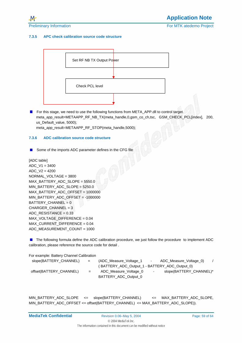
Application Note Preliminary Information For MTK atedemo Project
MediaTek Confidential Revision 0.06–May 5, 2004 Page: 59 of 64 © 2004 MediaTek Inc.
The information contained in this document can be modified without notice
7.3.5 APC check calibration source code structure
For this stage, we need to use the following functions from META_APP.dll to control target. meta_app_result=METAAPP_RF_NB_TX(meta_handle,0,gsm_co_ch,tsc, GSM_CHECK_PCL[index], 200, us_Default_value, 5000); meta_app_result=METAAPP_RF_STOP(meta_handle,5000);
7.3.6 ADC calibration source code structure
Some of the imports ADC parameter defines in the CFG file
[ADC table] ADC_V1 = 3400 ADC_V2 = 4200 NORMAL_VOLTAGE = 3800 MAX_BATTERY_ADC_SLOPE = 5550.0 MIN_BATTERY_ADC_SLOPE = 5250.0 MAX_BATTERY_ADC_OFFSET = 1000000 MIN_BATTERY_ADC_OFFSET = -1000000 BATTERY_CHANNEL = 0 CHARGER_CHANNEL = 3 ADC_RESISTANCE = 0.33 MAX_VOLTAGE_DIFFERENCE = 0.04 MAX_CURRENT_DIFFERENCE = 0.04 ADC_MEASUREMENT_COUNT = 1000
The following formula define the ADC calibration procedure, we just follow the procedure to implement ADC calibration, please reference the source code for detail . For example: Battery Channel Calibration slope(BATTERY_CHANNEL) = (ADC_Measure_Voltage_1 - ADC_Measure_Voltage_0) /
( BATTERY_ADC_Output_1 - BATTERY_ADC_Output_0) offset(BATTERY_CHANNEL) = ADC_Measure_Voltage_0 - slope(BATTERY_CHANNEL)*
BATTERY_ADC_Output_0 MIN_BATTERY_ADC_SLOPE <= slope(BATTERY_CHANNEL) <= MAX_BATTERY_ADC_SLOPE, MIN_BATTERY_ADC_OFFSET <= offset(BATTERY_CHANNEL) <= MAX_BATTERY_ADC_SLOPE)).
Set RF NB TX Output Power
Check PCL level
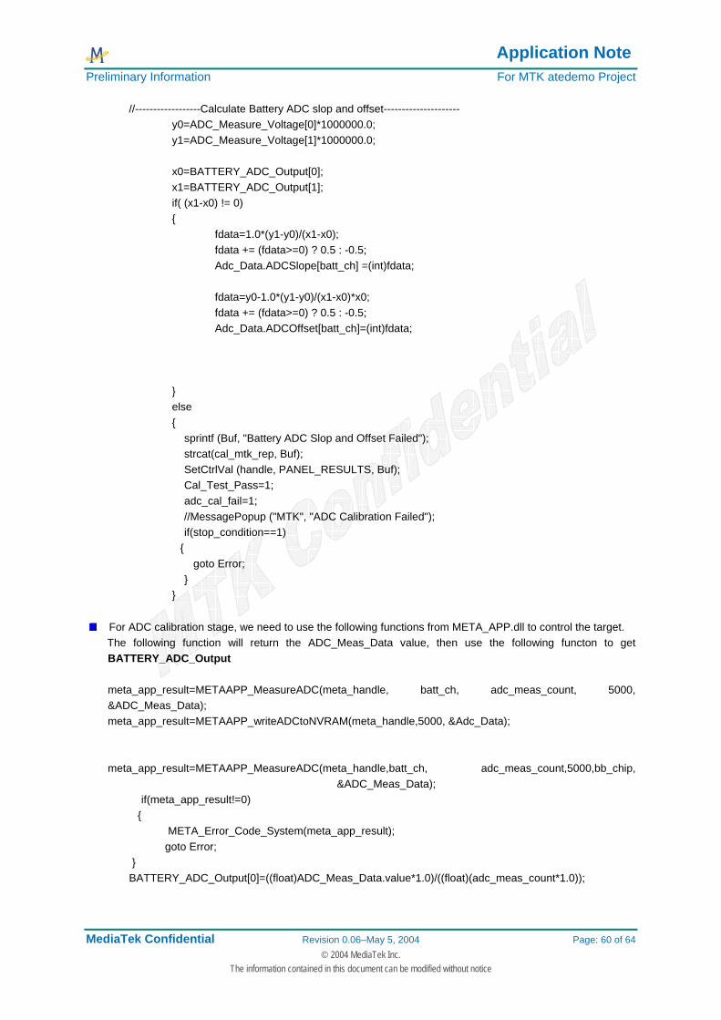
Application Note Preliminary Information For MTK atedemo Project
MediaTek Confidential Revision 0.06–May 5, 2004 Page: 60 of 64 © 2004 MediaTek Inc.
The information contained in this document can be modified without notice
//------------------Calculate Battery ADC slop and offset--------------------- y0=ADC_Measure_Voltage[0]*1000000.0; y1=ADC_Measure_Voltage[1]*1000000.0; x0=BATTERY_ADC_Output[0]; x1=BATTERY_ADC_Output[1]; if( (x1-x0) != 0) { fdata=1.0*(y1-y0)/(x1-x0); fdata += (fdata>=0) ? 0.5 : -0.5; Adc_Data.ADCSlope[batt_ch] =(int)fdata; fdata=y0-1.0*(y1-y0)/(x1-x0)*x0; fdata += (fdata>=0) ? 0.5 : -0.5; Adc_Data.ADCOffset[batt_ch]=(int)fdata; } else { sprintf (Buf, "Battery ADC Slop and Offset Failed"); strcat(cal_mtk_rep, Buf); SetCtrlVal (handle, PANEL_RESULTS, Buf); Cal_Test_Pass=1; adc_cal_fail=1; //MessagePopup ("MTK", "ADC Calibration Failed"); if(stop_condition==1) { goto Error; } }
For ADC calibration stage, we need to use the following functions from META_APP.dll to control the target. The following function will return the ADC_Meas_Data value, then use the following functon to get
BATTERY_ADC_Output
meta_app_result=METAAPP_MeasureADC(meta_handle, batt_ch, adc_meas_count, 5000, &ADC_Meas_Data); meta_app_result=METAAPP_writeADCtoNVRAM(meta_handle,5000, &Adc_Data);
meta_app_result=METAAPP_MeasureADC(meta_handle,batt_ch, adc_meas_count,5000,bb_chip, &ADC_Meas_Data);
if(meta_app_result!=0) { META_Error_Code_System(meta_app_result); goto Error; } BATTERY_ADC_Output[0]=((float)ADC_Meas_Data.value*1.0)/((float)(adc_meas_count*1.0));
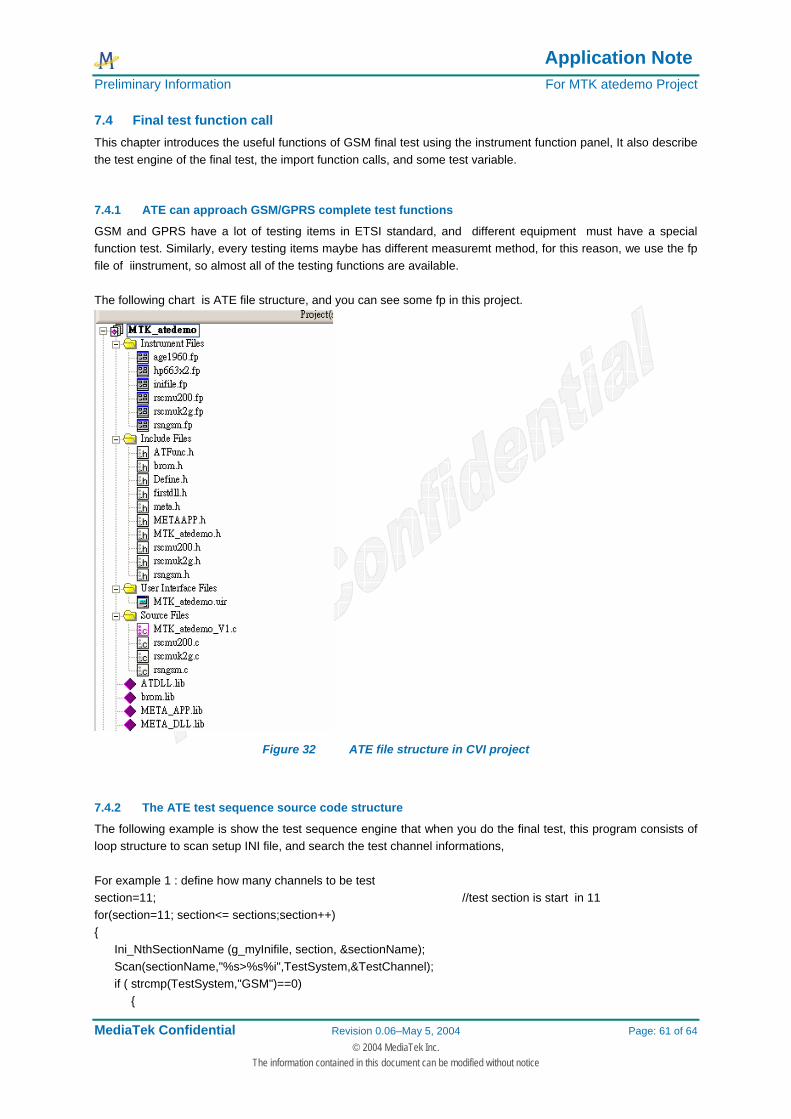
Application Note Preliminary Information For MTK atedemo Project
MediaTek Confidential Revision 0.06–May 5, 2004 Page: 61 of 64 © 2004 MediaTek Inc.
The information contained in this document can be modified without notice
7.4 Final test function call This chapter introduces the useful functions of GSM final test using the instrument function panel, It also describe the test engine of the final test, the import function calls, and some test variable.
7.4.1 ATE can approach GSM/GPRS complete test functions
GSM and GPRS have a lot of testing items in ETSI standard, and different equipment must have a special function test. Similarly, every testing items maybe has different measuremt method, for this reason, we use the fp file of iinstrument, so almost all of the testing functions are available. The following chart is ATE file structure, and you can see some fp in this project.
Figure 32 ATE file structure in CVI project
7.4.2 The ATE test sequence source code structure
The following example is show the test sequence engine that when you do the final test, this program consists of loop structure to scan setup INI file, and search the test channel informations, For example 1 : define how many channels to be test section=11; //test section is start in 11 for(section=11; section<= sections;section++) { Ini_NthSectionName (g_myInifile, section, §ionName); Scan(sectionName,"%s>%s%i",TestSystem,&TestChannel); if ( strcmp(TestSystem,"GSM")==0) {
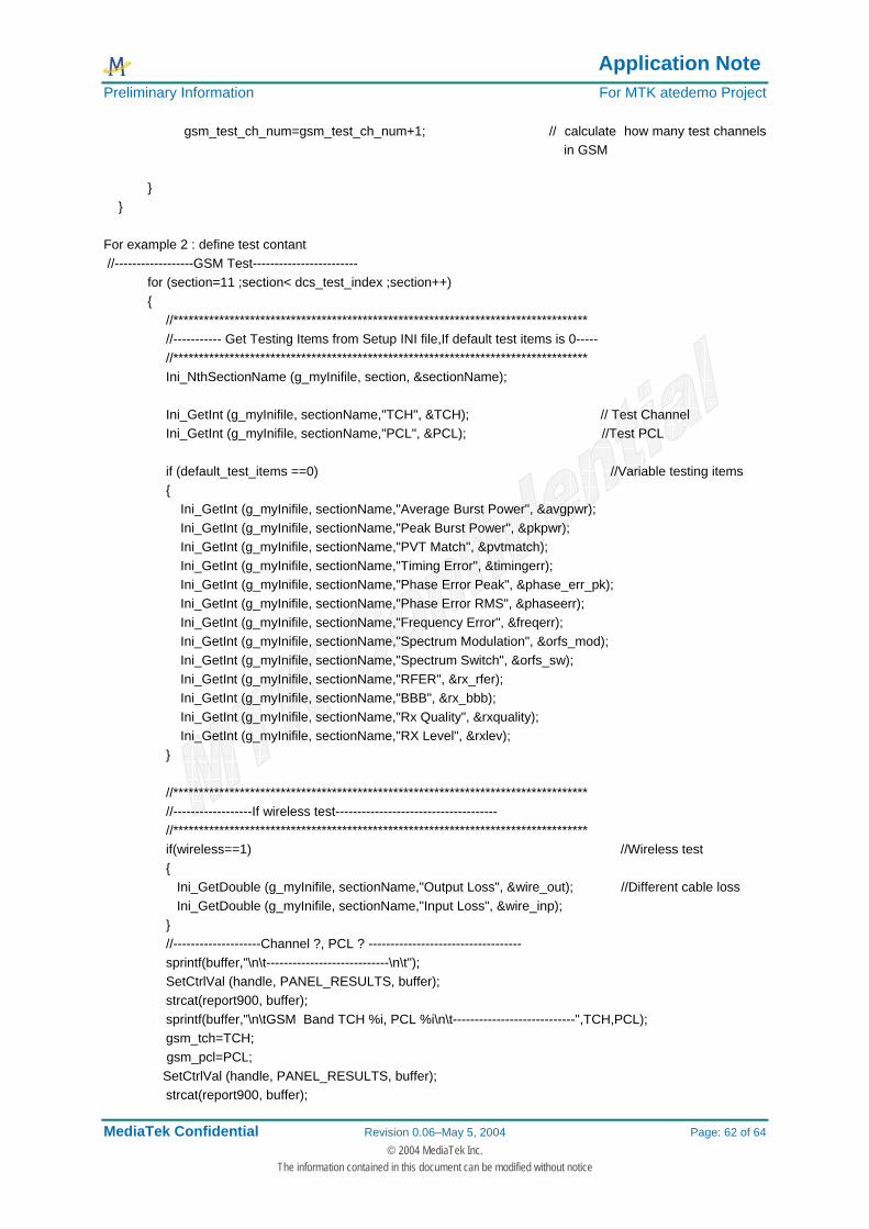
Application Note Preliminary Information For MTK atedemo Project
MediaTek Confidential Revision 0.06–May 5, 2004 Page: 62 of 64 © 2004 MediaTek Inc.
The information contained in this document can be modified without notice
gsm_test_ch_num=gsm_test_ch_num+1; // calculate how many test channels in GSM
} } For example 2 : define test contant //------------------GSM Test------------------------ for (section=11 ;section< dcs_test_index ;section++) { //********************************************************************************* //----------- Get Testing Items from Setup INI file,If default test items is 0----- //********************************************************************************* Ini_NthSectionName (g_myInifile, section, §ionName); Ini_GetInt (g_myInifile, sectionName,"TCH", &TCH); // Test Channel Ini_GetInt (g_myInifile, sectionName,"PCL", &PCL); //Test PCL if (default_test_items ==0) //Variable testing items { Ini_GetInt (g_myInifile, sectionName,"Average Burst Power", &avgpwr); Ini_GetInt (g_myInifile, sectionName,"Peak Burst Power", &pkpwr); Ini_GetInt (g_myInifile, sectionName,"PVT Match", &pvtmatch); Ini_GetInt (g_myInifile, sectionName,"Timing Error", &timingerr); Ini_GetInt (g_myInifile, sectionName,"Phase Error Peak", &phase_err_pk); Ini_GetInt (g_myInifile, sectionName,"Phase Error RMS", &phaseerr); Ini_GetInt (g_myInifile, sectionName,"Frequency Error", &freqerr); Ini_GetInt (g_myInifile, sectionName,"Spectrum Modulation", &orfs_mod); Ini_GetInt (g_myInifile, sectionName,"Spectrum Switch", &orfs_sw); Ini_GetInt (g_myInifile, sectionName,"RFER", &rx_rfer); Ini_GetInt (g_myInifile, sectionName,"BBB", &rx_bbb); Ini_GetInt (g_myInifile, sectionName,"Rx Quality", &rxquality); Ini_GetInt (g_myInifile, sectionName,"RX Level", &rxlev); } //********************************************************************************* //------------------If wireless test------------------------------------- //********************************************************************************* if(wireless==1) //Wireless test { Ini_GetDouble (g_myInifile, sectionName,"Output Loss", &wire_out); //Different cable loss Ini_GetDouble (g_myInifile, sectionName,"Input Loss", &wire_inp); } //--------------------Channel ?, PCL ? ----------------------------------- sprintf(buffer,"\n\t----------------------------\n\t"); SetCtrlVal (handle, PANEL_RESULTS, buffer); strcat(report900, buffer); sprintf(buffer,"\n\tGSM Band TCH %i, PCL %i\n\t----------------------------",TCH,PCL); gsm_tch=TCH; gsm_pcl=PCL; SetCtrlVal (handle, PANEL_RESULTS, buffer); strcat(report900, buffer);
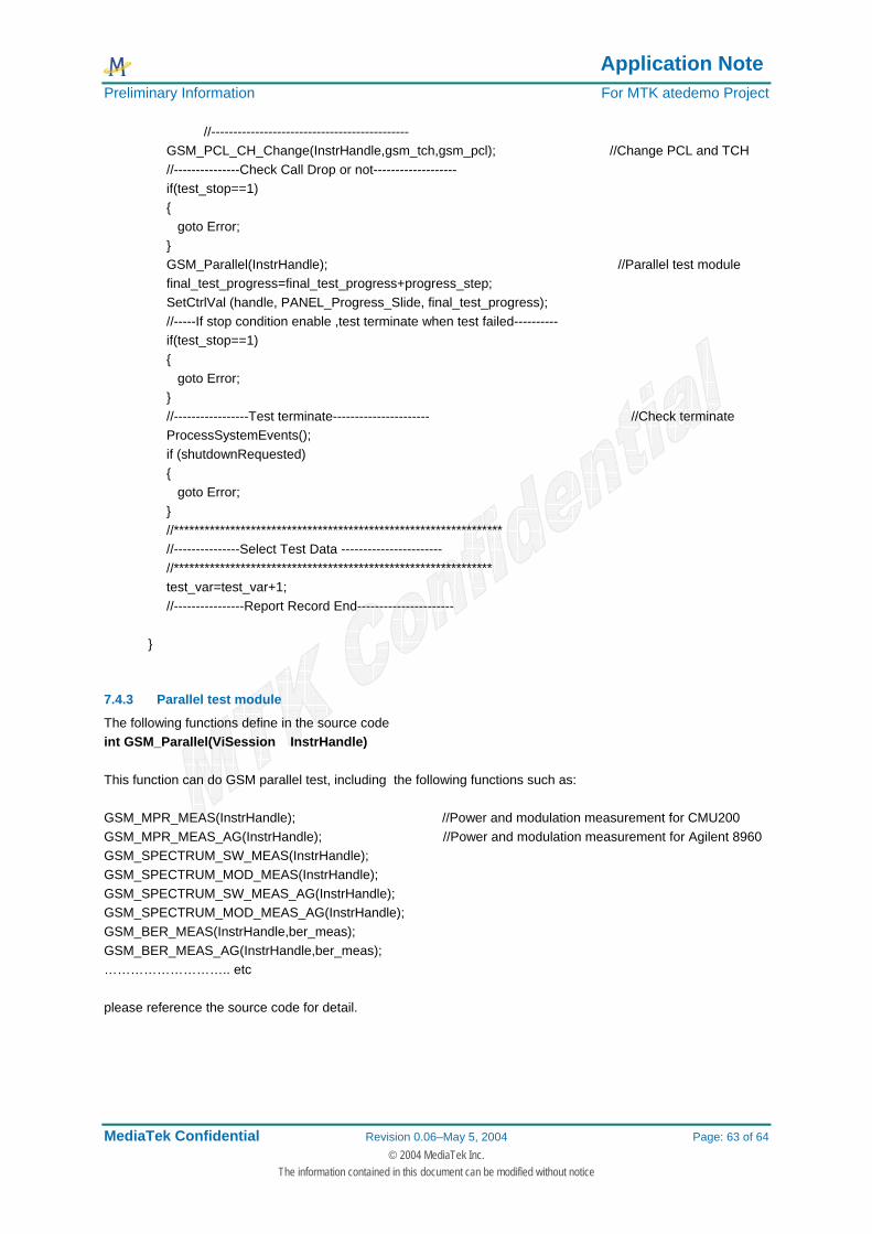
Application Note Preliminary Information For MTK atedemo Project
MediaTek Confidential Revision 0.06–May 5, 2004 Page: 63 of 64 © 2004 MediaTek Inc.
The information contained in this document can be modified without notice
//--------------------------------------------- GSM_PCL_CH_Change(InstrHandle,gsm_tch,gsm_pcl); //Change PCL and TCH //---------------Check Call Drop or not------------------- if(test_stop==1) { goto Error; } GSM_Parallel(InstrHandle); //Parallel test module final_test_progress=final_test_progress+progress_step; SetCtrlVal (handle, PANEL_Progress_Slide, final_test_progress); //-----If stop condition enable ,test terminate when test failed---------- if(test_stop==1) { goto Error; } //-----------------Test terminate---------------------- //Check terminate ProcessSystemEvents(); if (shutdownRequested) { goto Error; } //**************************************************************** //---------------Select Test Data ----------------------- //************************************************************** test_var=test_var+1; //----------------Report Record End---------------------- }
7.4.3 Parallel test module
The following functions define in the source code int GSM_Parallel(ViSession InstrHandle) This function can do GSM parallel test, including the following functions such as: GSM_MPR_MEAS(InstrHandle); //Power and modulation measurement for CMU200 GSM_MPR_MEAS_AG(InstrHandle); //Power and modulation measurement for Agilent 8960 GSM_SPECTRUM_SW_MEAS(InstrHandle); GSM_SPECTRUM_MOD_MEAS(InstrHandle); GSM_SPECTRUM_SW_MEAS_AG(InstrHandle); GSM_SPECTRUM_MOD_MEAS_AG(InstrHandle); GSM_BER_MEAS(InstrHandle,ber_meas); GSM_BER_MEAS_AG(InstrHandle,ber_meas); ……………………….. etc please reference the source code for detail.
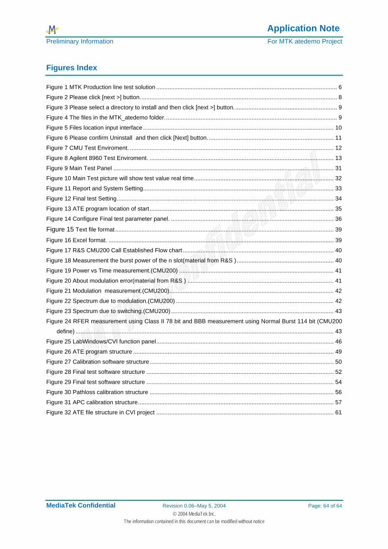
Application Note Preliminary Information For MTK atedemo Project
MediaTek Confidential Revision 0.06–May 5, 2004 Page: 64 of 64 © 2004 MediaTek Inc.
The information contained in this document can be modified without notice
Figures Index
Figure 1 MTK Production line test solution .............................................................................................................. 6 Figure 2 Please click [next >] button........................................................................................................................ 8 Figure 3 Please select a directory to install and then click [next >] button............................................................... 9 Figure 4 The files in the MTK_atedemo folder......................................................................................................... 9 Figure 5 Files location input interface .................................................................................................................... 10 Figure 6 Please confirm Uninstall and then click [Next] button. ............................................................................ 11 Figure 7 CMU Test Enviroment. ............................................................................................................................ 12 Figure 8 Agilent 8960 Test Enviroment. ................................................................................................................ 13 Figure 9 Main Test Panel ...................................................................................................................................... 31 Figure 10 Main Test picture will show test value real time..................................................................................... 32 Figure 11 Report and System Setting.................................................................................................................... 33 Figure 12 Final test Setting.................................................................................................................................... 34 Figure 13 ATE program location of start ................................................................................................................ 35 Figure 14 Configure Final test parameter panel. ................................................................................................... 36 Figure 15 Text file format ..................................................................................................................................... 39 Figure 16 Excel format. ......................................................................................................................................... 39 Figure 17 R&S CMU200 Call Established Flow chart............................................................................................ 40 Figure 18 Measurement the burst power of the n slot(material from R&S ) ........................................................... 40 Figure 19 Power vs Time measurement.(CMU200) .............................................................................................. 41 Figure 20 About modulation error(material from R&S ) ......................................................................................... 41 Figure 21 Modulation measurement.(CMU200).................................................................................................... 42 Figure 22 Spectrum due to modulation.(CMU200) ................................................................................................ 42 Figure 23 Spectrum due to switching.(CMU200) ................................................................................................... 43 Figure 24 RFER measurement using Class II 78 bit and BBB measurement using Normal Burst 114 bit (CMU200
define) ............................................................................................................................................................. 43 Figure 25 LabWindows/CVI function panel............................................................................................................ 46 Figure 26 ATE program structure .......................................................................................................................... 49 Figure 27 Calibration software structure................................................................................................................ 50 Figure 28 Final test software structure .................................................................................................................. 52 Figure 29 Final test software structure .................................................................................................................. 54 Figure 30 Pathloss calibration structure ................................................................................................................ 56 Figure 31 APC calibration structure....................................................................................................................... 57 Figure 32 ATE file structure in CVI project ............................................................................................................ 61