
MSIP: A Protocol for E cient Hando s of Real-time Multimedia
46
MSIP: A Protocol for Efficient Handoffs of Real-time Multimedia Sessions in Mobile Wireless Scenarios Dissertation submitted in partial fulfillment of the requirements for the degree of Master of Technology by Ranjeeth Kumar A Roll No: 02329018 under the guidance of Prof. Sridhar Iyer Kanwal Rekhi School of Information Technology Indian Institute of Technology, Bombay Mumbai - 400076. 2003
Transcript of MSIP: A Protocol for E cient Hando s of Real-time Multimedia

MSIP: A Protocol for Efficient Handoffs of
Real-time Multimedia Sessions in Mobile
Wireless Scenarios
Dissertation
submitted in partial fulfillment of the requirements
for the degree of
Master of Technology
by
Ranjeeth Kumar A
Roll No: 02329018
under the guidance of
Prof. Sridhar Iyer
Kanwal Rekhi School of Information Technology
Indian Institute of Technology, Bombay
Mumbai - 400076.
2003

ii

Dedicated to
my Family, Thoops,
my Friends
and
All the Orphans in this world

Dissertation Approval Sheet
This is to certify that the dissertation titled
MSIP: A Protocol for Efficient Handoffs of Real-time Multimedia Sessions
in Mobile Wireless Scenarios
By
Ranjeeth Kumar A
(02329018)
is approved for the degree of Master of Technology.
Prof. Sridhar Iyer
(Guide)
Internal Examiner
External Examiner
Chairperson
Date :
v
Abstract
The support for IP mobility has become very important with the increasing growth
of mobile applications. One of the key challenges for the deployment of such wireless
Internet infrastructure is to efficiently manage user mobility. Mobility is handled by
Mobile IP (at the network layer) and Session Initiation Protocol (at the application
layer). The main aim of these schemes is to provide seamless connectivity for ongoing
communications, that is, to keep the handoff latency delay as less as possible. The
delay constraint becomes even more crucial for real-time applications. The Mobile IP
scheme has drawbacks like triangular routing, longer delays and the need for tunneling
management. SIP solves many of the problems in Mobile IP, but it involves the time
consuming process of obtaining a new IP address from the DHCP server.
In this report, we propose a hybrid scheme, MSIP, that is the integration of Mobile
IP and SIP. MSIP reduces the handoff delay for real time applications. It avoids the
need for tunneling the packets through out the handoff period and the communication
need not be hung up till a new IP is given by the DHCP server. Thus MSIP gives better
performance than Mobile IP ans SIP, for real-time applications.

vi
Acknowledgments
I express my sincere gratitude towards my guide Prof. Sridhar Iyer for his constant
help, encouragement and inspiration through out the project work. Without his invalu-
able guidance, this work would never have been a successful one. I would also like to
thank the members of the Mobile Computing Research Group at KReSIT, namely Ashish
Shinde, Srinath Perur, Raghu, Vijay Rajsinghani, Nitin Salodkar, Vijaya Kumar, Sayed
Imranali, Kiran Diwakar, Kalyan Rao, and Kalpesh Patel for their valuable suggestions
and helpful discussions. I would also like to thank all my friends at KReSIT, for their
support and encouragement.
Ranjeeth Kumar A
IIT Bombay
July 09, 2004

Contents
Abstract v
Acknowledgments vi
List of Figures ix
Abbreviations ix
1 Introduction 1
1.1 Introduction to Wireless Networks . . . . . . . . . . . . . . . . . . . . . 1
1.2 Challenges of Mobility in Wireless Networks . . . . . . . . . . . . . . . . 1
1.2.1 IP and Routing . . . . . . . . . . . . . . . . . . . . . . . . . . . . 1
1.2.2 Delay Issues . . . . . . . . . . . . . . . . . . . . . . . . . . . . . . 2
1.3 Related Work . . . . . . . . . . . . . . . . . . . . . . . . . . . . . . . . . 2
1.4 Thesis Objective and Scope . . . . . . . . . . . . . . . . . . . . . . . . . 3
1.5 Thesis Outline . . . . . . . . . . . . . . . . . . . . . . . . . . . . . . . . 3
2 Mobile IP 5
2.1 Overview . . . . . . . . . . . . . . . . . . . . . . . . . . . . . . . . . . . 5
2.1.1 Main Functions in Mobile IP . . . . . . . . . . . . . . . . . . . . 6
2.2 How Mobile IP Works . . . . . . . . . . . . . . . . . . . . . . . . . . . . 6
2.3 Problems with Mobile IP . . . . . . . . . . . . . . . . . . . . . . . . . . 7
2.4 Summary . . . . . . . . . . . . . . . . . . . . . . . . . . . . . . . . . . . 8
3 Session Initiation Protocol : SIP 9
3.1 Overview . . . . . . . . . . . . . . . . . . . . . . . . . . . . . . . . . . . 9
3.2 How SIP Works . . . . . . . . . . . . . . . . . . . . . . . . . . . . . . . . 11
3.2.1 SIP with Proxy Server . . . . . . . . . . . . . . . . . . . . . . . . 11
vii
viii CONTENTS
3.2.2 SIP with Redirect Server . . . . . . . . . . . . . . . . . . . . . . 12
3.3 Problems with SIP . . . . . . . . . . . . . . . . . . . . . . . . . . . . . . 14
3.4 Summary . . . . . . . . . . . . . . . . . . . . . . . . . . . . . . . . . . . 14
4 Motivation for MSIP 15
4.1 Motivation . . . . . . . . . . . . . . . . . . . . . . . . . . . . . . . . . . 15
4.2 Problem Statement . . . . . . . . . . . . . . . . . . . . . . . . . . . . . . 16
5 MSIP Proposed Solution 17
5.1 Overview . . . . . . . . . . . . . . . . . . . . . . . . . . . . . . . . . . . 17
5.2 How MSIP Works . . . . . . . . . . . . . . . . . . . . . . . . . . . . . . 17
5.3 Advantages . . . . . . . . . . . . . . . . . . . . . . . . . . . . . . . . . . 19
5.4 Summary . . . . . . . . . . . . . . . . . . . . . . . . . . . . . . . . . . . 20
6 MSIP Implementation in NS 21
6.1 Node Architecture in NS . . . . . . . . . . . . . . . . . . . . . . . . . . . 21
6.1.1 Mobile IP . . . . . . . . . . . . . . . . . . . . . . . . . . . . . . . 21
6.1.2 Session Initiation Protocol . . . . . . . . . . . . . . . . . . . . . . 22
6.2 MSIP Node Architecture . . . . . . . . . . . . . . . . . . . . . . . . . . . 23
7 Simulation and Results 27
7.1 Simulation SetUp . . . . . . . . . . . . . . . . . . . . . . . . . . . . . . . 27
7.1.1 Aim of the experiments . . . . . . . . . . . . . . . . . . . . . . . 27
7.2 Scenario and Results . . . . . . . . . . . . . . . . . . . . . . . . . . . . . 28
7.3 Analysis on Results . . . . . . . . . . . . . . . . . . . . . . . . . . . . . . 29
8 Future Work and Conclusions 31
Bibliography 33
List of Figures
2.1 Working of Mobile IP . . . . . . . . . . . . . . . . . . . . . . . . . . . . 7
3.1 Working of SIP . . . . . . . . . . . . . . . . . . . . . . . . . . . . . . . . 10
3.2 SIP in presence of a Proxy Server . . . . . . . . . . . . . . . . . . . . . . 11
3.3 SIP in presence of a Redirect Server . . . . . . . . . . . . . . . . . . . . 13
3.4 Delay involved in DHCP . . . . . . . . . . . . . . . . . . . . . . . . . . . 14
5.1 Working of MSIP . . . . . . . . . . . . . . . . . . . . . . . . . . . . . . . 18
5.2 Message flow during a Handoff . . . . . . . . . . . . . . . . . . . . . . . 19
6.1 Node Architecture in Mobile IP . . . . . . . . . . . . . . . . . . . . . . . 21
6.2 SIP in Protocol Stack . . . . . . . . . . . . . . . . . . . . . . . . . . . . 22
6.3 DHCP implementation in NS . . . . . . . . . . . . . . . . . . . . . . . . 24
6.4 MSIP in NS . . . . . . . . . . . . . . . . . . . . . . . . . . . . . . . . . . 25
7.1 Simple Topology . . . . . . . . . . . . . . . . . . . . . . . . . . . . . . . 28
7.2 Delay in MIP Vs MSIP . . . . . . . . . . . . . . . . . . . . . . . . . . . 29
7.3 Disruption Time vs. Delay . . . . . . . . . . . . . . . . . . . . . . . . . . 30
ix

x LIST OF FIGURES

Abbreviations
MN Mobile Node
CN Correspondent Node
MIP Mobile IP
SIP Session Initiation Protocol
MA Mobility Agent
HMA Home Mobility Agent
FMA Foreign Mobility Agent
DHCP Dynamic Host Configuration Protocol
BS Base Station
MH Mobile Host
CoA Care of Address
DAD Duplicate Address Detection
xi

LIST OF FIGURES
xii
Chapter 1
Introduction
1.1 Introduction to Wireless Networks
In recent times, the wireless networks have become very popular. With the ever in-
creasing use of mobile devices, the demand for host mobility and support for various
mobile applications is also growing considerably. Wireless LANs are being deployed on
airports, conferences, etc. People have started using portable laptops to access Internet
and other resources using wireless networks while moving. For any mobile node, if it
wants to take full advantage of this mobility provided, the mobile node should be able
to move to any point in the network and still retain all its ongoing communications.
1.2 Challenges of Mobility in Wireless Networks
Multihop wireless networks are faced by challenges not present in the wired networks.
Mobility of stations in wireless networks gives rise to issues like route changes, link
failures, and need for change of IP addresses. These reasons require changes at various
layers of protocol stack.
1.2.1 IP and Routing
The stations in wireless network do not remain in the same subnet due to mobility; hence
either their IP addresses need to be changed and/or the packets should be forwarded to
them. These requirements have lead to development of mobile IP[1] where the addresses
are assigned to mobile hosts dynamically and the packets are appropriately forwarded
to them. Session Initiation Protocol[6] handles mobility at the application layer. In
1

Chapter 1. Introduction
SIP, the node, when moves to a foreign domain, gets a new IP address from the DHCP
server, and resumes its communication at the new IP address.
1.2.2 Delay Issues
The cell handoff delay is the period of time between the moment at which the mobile
node detects the subnet change, and the time at which it receives the first packet of
its ongoing communication in the new subnet. Existing mobility protocols have mainly
been designed for network, and application layers, and the majority of studies refer to
the inherent mobility support provided by the wireless network. The primary design
goal of any scheme, that handles mobility, is to keep the handoff delay as less as possi-
ble. If the applications are real-time then this constraint on delay becomes even more
crucial, as the real time applications are highly delay-sensitive. Schemes like Mobile IP
and SIP exist that handle mobility at network and application layers respectively, but
there are several issues that are yet to be resolved in these schemes. The problem with
the Mobile IP scheme is the very famous triangular routing problem, and also that all
the packets need to be tunneled through the home agent, to the foreign agent and then
to the mobile node, leading to much longer delays[1][5] . The problem with SIP is that
after the the mobile node moves to a new subnet, it should contact a DHCP server to
get a new IP[6] , and then inform the other communicating party about its new IP. The
process of getting a new IP from the DHCP server is quite time consuming.
1.3 Related Work
Several schemes have been proposed to handle mobility in IP networks and voice appli-
cations. One such scheme is Mobile Voice Over IP, an application-level protocol [8]to
support terminal mobility in real-time applications such as voice over IP, on a wireless
local area network. Its implementation is based on the ITU-T H.323 protocol bound-
aries in the network. Mobile Voice over IP (MVOIP), provides a mechanism to maintain
a VOIP call even as the underlying network addresses of the hosts engaged in the call
need to change.
2
1.4 Thesis Objective and Scope
1.4 Thesis Objective and Scope
This work aims at improving the performance for real-time applications, in terms of
delay, by using MSIP, a combination of network and application layer mobility manage-
ment models. MSIP reduces the signaling load and provides fast handoff for ongoing
conversations. The main focus of this work is to present the design and architecture
of MSIP. The implementation of MSIP in Network Simulator NS-2 is presented, and
simulation results are discussed. The scope of this work is limited to IPV4 networks,
not to IPV6. This is due to inclusion of Route Optimization in IPV6, which avoids the
longer delays due to triangular routing.
1.5 Thesis Outline
The rest of the thesis is outlined in this section. In Second chapter, Mobile IP scheme
is discussed in detail. The working of Mobile IP, and problems of using it for real-time
applications are also discussed there. Third chapter discusses the operation of Session
Initiation Protocol, and describes the drawbacks in SIP. In chapter four, the motivation
for MSIP to improve the handoff delay is explained. Fifth chapter explains the design
and working of MSIP in detail. Sixth chapter describes the MSIP implementation in
NS. The simulation set up and results are discussed in chapter seven. Finally, thesis
ends with the conclusion and the scope for the future work in chapter eight.
3

Chapter 1. Introduction
4
Chapter 2
Mobile IP
2.1 Overview
Mobile IP is a transparent solution that handles mobility at the network layer. This
scheme was designed to solve the mobility problem by allowing the mobile node to
use two IP addresses: a fixed home address and a care-of address that changes at
each new point of attachment. This solution is transparent because, when two nodes
communicate with each other and one of them moves to a new subnet, then the other
node is completely unaware of this mobility, and it continues its communication as if
nothing has happened. In Mobile IP, it is assumed that every mobile node (MN) has its
home network, and a statically allocated IP address on its home network. In Mobile IP,
the support for mobility is provided by adding IP tunneling to IP routing. The Mobile
IP architecture mainly consists of
1. Mobile Nodes (MN)
2. Correspondent Nodes (CN) : The CN participates in communication with the MN.
The CN can be either fixed or a mobile node.
3. Home Agents (HA) : The default router on the home network, HA stores the
current locations of all the mobile nodes in its network. It intercepts the packets
from CN and tunnels them to the current location of the mobile node.
4. foreign Agents (FA) : The default router on the foreign network, FA receives the
tunneled packets from HA and forwards them to the MN in its network.
5
Chapter 2. Mobile IP
2.1.1 Main Functions in Mobile IP
Mobile IP consists of three main functions[13],
1. Mobile agent discovery: When a mobile node is away from home, it wants to find
agents so it does not lose access to the Internet. There are two ways of finding
agents. The first is by selecting an agent from among those periodically advertised,
and the second is by sending out a periodic solicitation until it receives a response
from a mobility agent. The mobile node thus gets its care-of-address which may
be dynamically assigned or associated with its foreign agent.
2. Registration with home agent: The mobile node registers its care-of-address
with its home agent in order to obtain service. The registration process can be
performed directly from the mobile node, or relayed by the foreign agent to the
home agent, depending on whether the care-of-address was dynamically assigned
or associated with its foreign agent. Note that simultaneous registrations with
multiple care-of-addresses is possible.
3. Packet delivery using IP tunneling: This is the period after the registration
process and before the service time expiration, provided that the mobile node
stays in the service area. During this period, the mobile node gets forwarded
packets from its foreign agent which were originally sent from the mobile node’s
home agent. Tunneling is the method used to forward the message from home
agent to foreign agent and finally to mobile node.
2.2 How Mobile IP Works
The Home agents and the foreign agents will broadcast agent advertisements in their
subnets. The mobile node detects that it has moved to a new subnet, when it hears the
advertisement from an agent which is not its HA. Then it sends a registration request
to its HA through FA with a care-of-address(CoA), which is generally the address of
the foreign agent itself. The HA then replies either accepting or denying that request.
The CN will be completely unaware of this mobility and will transmit the packets to
the mobile nodes home address. The HA will intercept these packets and performs the
IP-in-IP encapsulation and tunnels them to the CoA of the mobile node (FA). The FA
then decapsulates the packets and forwards them to the mobile node.
6

2.3 Problems with Mobile IP
Figure 2.1: Working of Mobile IP
2.3 Problems with Mobile IP
The famous problem with Mobile IP is triangular routing. All the packets from CN to
MN, should take the longer path from CN to HA, from HA to FA, and then from FA to
MN, whereas the packets from MN to CN, go directly to CN. One solution was proposed
to solve this problem, Route Optimization.
Route Optimization : Route optimization solves the triangular routing problem
by using binding updates to inform the correspondent host about the current IP address.
However, route optimization has several drawbacks[6] :
1. Route optimization requires changes in the IP stack of the correspondent host,
since it must be able to encapsulate IP packets, and store care-of addresses of the
foreign agent or mobile host.
2. Only the home agent may send binding updates to correspondent hosts. This
means that there will be an extra delay before the correspondent host finds out
where to send the packets, during which the old foreign agent must forward the
packets to the correct location.
3. The mobile host needs to rely on the old foreign agent forwarding packets to its
new foreign agent until the correspondent host has got the binding update. There
is no requirement saying that the foreign agent must do so.
7

Chapter 2. Mobile IP
Because of the requirements that are put on the correspondent hosts, it cannot be
expected that route optimization will be widely employed in a near future. Moreover,
the home and foreign agent can become bottlenecks since they must handle the tunnels
for a possibly large number of mobile hosts.
2.4 Summary
Mobile IP provides transparent mobility which is needed to keep TCP connections alive
when the user is moving. This is because, Mobile IP does not require the change of
IP address with the change in point of attachment of the node, thus Mobile IP is the
right choice for such applications. This scheme is not suitable for real-time applications
because of long tunneling delays.
8

Chapter 3
Session Initiation Protocol : SIP
3.1 Overview
The Session Initiation Protocol (SIP) is the application-layer solution to handle mobility.
This protocol is used for establishing and tearing down multimedia sessions[6]. SIP is
a control-signaling protocol and has been standardized by IETF for the invitation to
multicast conferences and Internet telephone calls.
There are certain functions or characteristics that a signaling protocol should be
capable of performing. They are
1. User Location function
2. Session or call establishment function
3. Session negotiation function
4. Call Participant Management function
5. Feature Invocation
In SIP, every user is addressed using an email-like address ”user@host”, where user
is a user name or phone number and host is a domain name or numerical address. The
SIP architecture consists of Registrar, User Agents, Proxy Server, Redirect Server.
The session is active when the first INVITE Request is issued and the call is estab-
lished. The session terminates when a BYE Request is issued. It also supports mobility
using proxy or redirecting servers to reach the Callee. SIP is also independent of trans-
port protocol. SIP is a client-server protocol where the client generates the SIP Request
messages while the server receives the messages and send responses. There are three
9

Chapter 3. Session Initiation Protocol : SIP
Figure 3.1: Working of SIP
kinds of servers in use with SIP. They are namely the Proxy servers, Redirect Servers
and the User Agent Servers (UAS). When a Proxy Server receives a Request message, it
acts like a hop server or a router and forwards the Request message to the next Proxy
Server or the User Agent Server at the receiving end-system. As for a Redirect Server,
when it receives a Request message, it returns an IP address of the Callee’s User Agent
Sever so that the Caller, which is a client, would have to resend his/ her request to the
UAS.
SIP Methods
1. Register Every user will register itself with the Registrar. In turn Registrar binds a
permanent address to the current location. These registrations are not permanent,
these will expire after certain period of time thus requiring periodic registrations.
2. Invite This method is generally invoked at the beginning of a communication.
Session description messages will be exchanged during this period. This function
could also be invoked when the state of the session has changed or has to be
changed.
3. Options Returns users capabilities to the requester.
4. ACK This is only used during the session initiation process, at the end of three
way handshake process.
10

3.2 How SIP Works
5. Cancel Terminates an incomplete session.
6. BYE Closes an open session.
The working of SIP in presence of proxy and redirect servers is explained in the
figure 3.2.
3.2 How SIP Works
3.2.1 SIP with Proxy Server
Figure 3.2: SIP in presence of a Proxy Server
The above figure shows the working of SIP in the presence of a proxy server. The
steps are as follows:
1. SIP Client at Caller A site tries to translate the domain abc.com to an IP address
where the server can be found. Once this is complete, Caller A issues the INVITE
request.
2. Caller A, also known as the User Agent Client (UAC), creates a session with an
INVITE request for Callee B, sip:[email protected]. This request is forwarded to the
11

Chapter 3. Session Initiation Protocol : SIP
SIP Proxy Server of B. This proxy server at B s site looks for Callee B at the
abc.com domain in its Location Server, usually a DNS. The Location Server or
DNS then returns the reply that Callee B is known locally.
3. The Proxy Server then re forwards the request message to Callee B, the host
location which is also the User Agent Server (UAS).
4. Callee B accepts the request and a response is returned through the Proxy Server,
and sends 200 message, which means OK.
5. The Proxy Server then forwards the message to Caller A to indicate that the
request is a success.
6. Caller A or UAC, returns an ACK message to the Proxy Server for the UAS of
Callee B to mean that Caller A acknowledges the last response from Callee B.
7. Finally, this forwarded message reaches Callee B or the UAS. Once this ACK is
received, the call is ready to begin. The call will only end when a BYE request is
issued, which is then followed by the 200 OK message and finally the ACK message
back for 200 OK.
3.2.2 SIP with Redirect Server
The above figure 3.3 shows the working of SIP in the presence of a Redirect server. The
steps followed are :
1. Caller A, creates a session with an INVITE request for Callee B, sip:[email protected].
This request is forwarded to the SIP Redirect Server of B.
2. This redirect server at B s site looks for Callee B at the abc.com domain in its
Location Server, usually a DNS.
3. The Location Server or DNS then returns the reply that Callee B is logged in as
BDomain.abc.com. The redirect server knows this through a static configuration,
database entry or dynamic binding set up by Callee B with a SIP REGISTER
message.
4. Caller A or UAC sends an ACK message to the Redirect Server that it received
its response message.
12
3.2 How SIP Works
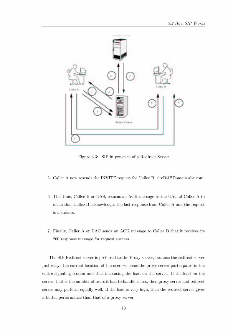
Figure 3.3: SIP in presence of a Redirect Server
5. Caller A now resends the INVITE request for Callee B, sip:[email protected].
6. This time, Callee B or UAS, returns an ACK message to the UAC of Caller A to
mean that Callee B acknowledges the last response from Caller A and the request
is a success.
7. Finally, Caller A or UAC sends an ACK message to Callee B that it receives its
200 response message for request success.
The SIP Redirect server is preferred to the Proxy server, because the redirect server
just relays the current location of the user, whereas the proxy server participates in the
entire signaling session and thus increasing the load on the server. If the load on the
server, that is the number of users it had to handle is less, then proxy server and redirect
server may perform equally well. If the load is very high, then the redirect server gives
a better performance than that of a proxy server.
13

Chapter 3. Session Initiation Protocol : SIP
3.3 Problems with SIP
1. SIP is not preferred for TCP applications.
2. The process of getting a new IP from the DHCP server involves a significant
amount of delay (typically 1-2 sec). The messages involved in this process is
explained in the figure 3.4.
Figure 3.4: Delay involved in DHCP
3. The communication resumes more quickly in Mobile IP than SIP. In Mobile IP, this
communication starts as soon as the mobile node hears the Agent advertisement
in the new subnet, which is not the case with SIP.
3.4 Summary
Session Initiation Protocol solves many of the problems of Mobile IP, like triangular
routing, longer tunneling delays. The performance of SIP also depends on the DHCP
implementation. The delay involved in obtaining IP address from DHCP server is the
main bottle neck in the working of SIP. So, in DHCP implementation if the duplicate
address resolution DAD is done in the background after assigning the IP address to the
node, the performance improves a lot.
14
Chapter 4
Motivation for MSIP
4.1 Motivation
The real-time applications are highly delay-sensitive. In order to support mobility for
such applications, the main challenge would be to provide seamless connectivity for the
ongoing communications, with as lesser delay as possible. The motivation for MSIP is
to reduce the long delay problems associated with the existing schemes, Mobile IP and
SIP and improve th performance for real-time applications. These problems are
1. In Mobile IP all the packets for the entire session, the period in which the mobile
node (MN) is in foreign network, should travel through the longer path that from
correspondent node (CN) to home agent (HA) then to foreign agent (FA) and then
to MN, thus resulting in longer delays, not desirable for real time applications.
2. In SIP, the process of obtaining a new IP address from the DHCP server, when a
handoff occurs, involves lot of delay.
In spite of the above mentioned problems associated with Mobile IP and SIP, these
schemes have certain advantages over each other. In Mobile IP, after the node moves
to the new subnet, the communication resumes more quickly. This is because, the
agents will broadcast the advertisements periodically with available CoA’s. As soon
as the mobile node listens this advertisement it sends a registration to its home agent
and restarts the communication. In SIP, the packets need not be tunneled through the
longer path after the handoff, but can be sent directly to the node’s new location. The
main aim of MSIP is to reduce the handoff delay for real time applications by integrating
these good features from both Mobile IP and SIP. In this new scheme we introduce a
15
Chapter 4. Motivation for MSIP
agent called Mobility Agent which is an integration of SIP Redirect Server and Mobile
IP Home Agent.
4.2 Problem Statement
The real-time applications are highly delay sensitive. The handoff latency should be as
less as possible for such applications. Existing schemes Mobile IP and SIP have delay
problems in them, explained in the above paragraph. The main aim of this work is to
reduce the handoff disruption time and give better performance than Mobile IP and
SIP, for real-time applications.
16
Chapter 5
MSIP Proposed Solution
5.1 Overview
In this report, we propose MSIP, an integrated scheme, combination of Mobile IP and
SIP, that results in a very less handoff latency time. This combination of network and
application layer mobility management models reduces the signaling load and provides
fast handoff for ongoing conversations.
5.2 How MSIP Works
If the Correspondent Node(CN) wants to communicate with the Mobile node(MN), they
start the communication using the SIP call establishment mechanism. If the MN moves
to a new subnet, with the session being still active, then, the MN switches to Mobile
IP scheme and receives the packets in the new subnet with tunneling being done by its
Home Mobility Agent. The tunneling is required only until the MN receives a new IP
address from the DHCP server in the new subnet. As soon as the MN gets the new
IP, it sends the SIP REINVITE message, with the same Call-ID, to CN informing it
about its new IP. From then on, tunneling is stopped, and the packets will be sent to
the current location of the MN directly.
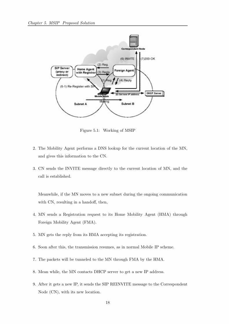
The detailed working of our new scheme is explained in figure 5.1
If Correspondent Node (CN) wants to communicate with Mobile Node (MN), then
1. CN sends an INVITE message to the Mobility Agent (MA) in MN’s home domain.
17
Chapter 5. MSIP Proposed Solution
Figure 5.1: Working of MSIP
2. The Mobility Agent performs a DNS lookup for the current location of the MN,
and gives this information to the CN.
3. CN sends the INVITE message directly to the current location of MN, and the
call is established.
Meanwhile, if the MN moves to a new subnet during the ongoing communication
with CN, resulting in a handoff, then,
4. MN sends a Registration request to its Home Mobility Agent (HMA) through
Foreign Mobility Agent (FMA).
5. MN gets the reply from its HMA accepting its registration.
6. Soon after this, the transmission resumes, as in normal Mobile IP scheme.
7. The packets will be tunneled to the MN through FMA by the HMA.
8. Mean while, the MN contacts DHCP server to get a new IP address.
9. After it gets a new IP, it sends the SIP REINVITE message to the Correspondent
Node (CN), with its new location.
18

5.3 Advantages
10. From then on, the packets will be sent directly to the MNs new current location
without tunneling.
11. The MN sends a SIP RE-REGISTER message to its HMA, so that any new con-
nections in future can be correctly redirected to the MN s current location.
The messages involved in the handoff process are given in figure 5.2 .
Figure 5.2: Message flow during a Handoff
5.3 Advantages
Our scheme, MSIP, overcomes the above mentioned problems associated with Mobile IP
and SIP. The communication resumes as soon as the node hears the agent advertisement
in the foreign network as it happens in Mobile IP, without waiting until the node obtains
the new IP address from the DHCP server asin SIP scheme. Also, the packets need not
be tunneled through the longer path, for the entire session as in Mobile IP.
19

Chapter 5. MSIP Proposed Solution
5.4 Summary
The gain in performance when MSIP is used, also depends on the DHCP implementation.
MSIP gives better performance for real-time applications. But still, for long-lived TCP
connections like Telnet, FTP, Mobile IP is preferred as it doesn’t involve the need for
change in IP addresses, with change in point of attachment.
20

Chapter 6
MSIP Implementation in NS
6.1 Node Architecture in NS
6.1.1 Mobile IP
Figure 6.1: Node Architecture in Mobile IP
21
Chapter 6. MSIP Implementation in NS
The HA and FA nodes are defined as MobileNode/MIPBS having a registering agent
(regagent ) that sends beacon out to the mobile nodes, sets up encapsulator and decap-
sulator, as required and replies to solicitations from MHs. The MH nodes are defined as
MobileNode/MIPMH which too have a regagent that receives and responds to beacons
and sends out solicitations to HA or FAs. The MobileNode/MIPMH node is very similar
to this except for the fact that it doesn’t have any encapsulator or decapsulator.
The MobileNode/MIPBS node routinely broadcasts beacon or advertisement mes-
sages out to MHs. A solicitation from a mobile node generates an ad that is send directly
to the requesting MH. The address of the base-station sending out beacon is heard by
MH and is used as the COA (care-of-address) of the MH. Thus as the MH moves from
its native to foreign domains, its COA changes. Upon receiving reg request (as reply to
ads) from a mobile host the base-station checks to see if it is the HA for the MH. If not,
it sets up its decapsulator and forwards the reg request towards the HA of the MH. In
case the base-station is the HA for the requesting MH but the COA doesn’t match its
own, it sets up an encapsulator and sends reg-request-reply back to the COA (address
of the FA) who has forwarded the reg request to it. so now all packets destined to the
MH reaching the HA would be tunneled through the encapsulator which encapsulates
the IP packet header with a IPinIP header, now destined to the COA instead of MH.
The FA s decapsulator receives this packet, removes the encapsulation and sends it to
the MH. If the COA matches that of the HA, it just removes the encapsulator it might
have set up (when its mobile host was roaming into foreign networks) and sends the
reply directly back to the MH, as the MH have now returned to its native domain.
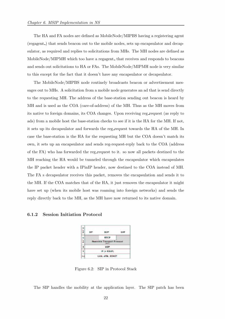
6.1.2 Session Initiation Protocol
Figure 6.2: SIP in Protocol Stack
The SIP handles the mobility at the application layer. The SIP patch has been
22
6.2 MSIP Node Architecture
downloaded from the National Institute of Standards Technology website. The patch
is applied on the NS2.1b9a version. The downloaded SIP patch was for wired scenario,
and mobility was not supported. In order to support mobility, DHCP agent had to be
included in NS. DHCP Agent would be responsible for allotting new IP addresses, when
requested for, to the mobile nodes roaming in the foreign domains. The pseudo code for
DHCP implementation is given in figure 6.3.
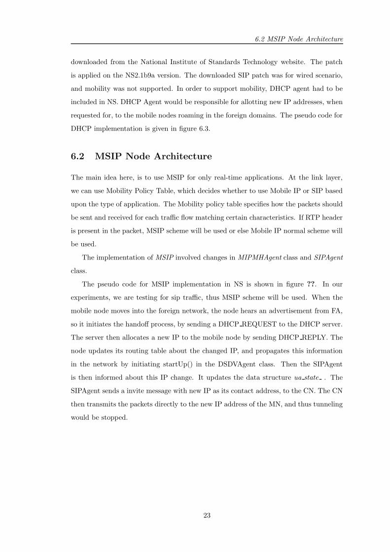
6.2 MSIP Node Architecture
The main idea here, is to use MSIP for only real-time applications. At the link layer,
we can use Mobility Policy Table, which decides whether to use Mobile IP or SIP based
upon the type of application. The Mobility policy table specifies how the packets should
be sent and received for each traffic flow matching certain characteristics. If RTP header
is present in the packet, MSIP scheme will be used or else Mobile IP normal scheme will
be used.
The implementation of MSIP involved changes in MIPMHAgent class and SIPAgent
class.
The pseudo code for MSIP implementation in NS is shown in figure ??. In our
experiments, we are testing for sip traffic, thus MSIP scheme will be used. When the
mobile node moves into the foreign network, the node hears an advertisement from FA,
so it initiates the handoff process, by sending a DHCP REQUEST to the DHCP server.
The server then allocates a new IP to the mobile node by sending DHCP REPLY. The
node updates its routing table about the changed IP, and propagates this information
in the network by initiating startUp() in the DSDVAgent class. Then the SIPAgent
is then informed about this IP change. It updates the data structure ua state . The
SIPAgent sends a invite message with new IP as its contact address, to the CN. The CN
then transmits the packets directly to the new IP address of the MN, and thus tunneling
would be stopped.
23

Chapter 6. MSIP Implementation in NS
MIPMHAgent::recv(Packet* p, Handler *h)
{
hdr_mip *miph = hdr_mip::access(p);
hdr_ip* iph = hdr_ip::access(p);
if (miph->type ==MIPT_ADS) {
if(iph->saddr() != ha_) {
miph->type = DHCP_REQUEST;
iph->daddr() = DHCP_Server;
send(p, 0);
}
}
if(miph->type == DHCP_REPLY) {
Change myNode_Addr = new_IP;
update_My_RouteTable();
// Propagate the change of IP in the network
DSDVAgent->startUp();
}
}
DHCPAgent::recv(Packet *p, Handler *h)
{
hdr_mip *miph = hdr_mip::access(p);
hdr_ip* iph = hdr_ip::access(p);
if(pkt->type == DHCP_REQUEST) {
//Allocate a new IP address
new_IP = allocate_NewIP();
miph->type = DHCP_REPLY;
send(p,0);
}
}
Figure 6.3: DHCP implementation in NS
24
6.2 MSIP Node Architecture
MIPMHAgent::recv(Packet* p, Handler *h)
{
hdr_mip *miph = hdr_mip::access(p);
hdr_ip* iph = hdr_ip::access(p);
if (miph->type ==MIPT_ADS) {
if(iph->saddr() != ha_) {
miph->type = DHCP_REQUEST;
iph->daddr() = DHCP_Server;
send(p, 0);
informSIPAgent(new_IP);
}
}
if(miph->type == DHCP_REPLY) {
Change myNode_Addr = new_IP;
update_My_RouteTable();
// Propogate the change of IP in the network
DSDVAgent->startUp();
}
}
SIPAgent::informSIPAgent(new_IP) {
// Change the Agent\’s node address in the
// data structure maintained by SIP Agent
ua_state_.caller_location.node_ = miph->newDHCPAddress;
((SIPAgent*) node_->SIP_AGENT)->addr()=miph->newDHCPAddress;
node_->address_ = miph->newDHCPAddress;
addr()=miph->newDHCPAddress;
sendInviteToCN(newIP);
}
Figure 6.4: MSIP in NS
25

Chapter 6. MSIP Implementation in NS
26

Chapter 7
Simulation and Results
7.1 Simulation SetUp
This chapter explains the simulation of MSIP. The simulations are done using the public
domain simulator NS-2. The SIP patch[9] has been applied on the NS2.19ba version.
The main aim of the experiments is to measure the handoff latency time and compare
with the existing schemes. The following are the assumptions that were made during
the simulation.
1. The DHCP delay, time taken for obtaining the a new IP address from the DHCP
server, is taken as 1.76 sec. This value is taken after practically measuring the
DHCP delay on the subnet of our department, KReSIT, IIT Bombay.
2. The DHCP server is present on the base station node itself.
3. The authentication delays are not considered in our simulations.
4. The transmission range of the nodes is 250m.
5. Mobile IPV4 is used.
7.1.1 Aim of the experiments
The main aim of the simulation is to measure the handoff disruption time. To compare
the performance of MSIP for real time applications with Mobile IP and SIP, in terms of
1. The time taken for the first packet to reach the destination after the handoff,
27
Chapter 7. Simulation and Results
HMA
FMA
1
2
3
4
5
8
9
10
W1
W0
W2
6 7
Figure 7.1: Simple Topology
2. The overall throughput, that is the number of packets transmitted in a given
amount of time.
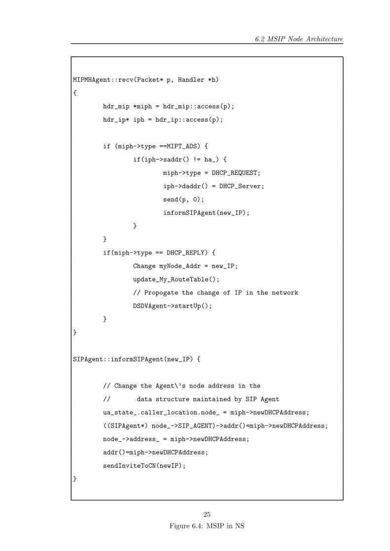
7.2 Scenario and Results
In the scenario taken for the simulation, all the nodes are placed in an area of size,
670m x 670m There are 3 domains, the home domain, the foreign domain and the wired
domain. There is 5 wireless nodes each, in the home and the foreign domain. The nodes
are numbered 1, 2, 3, 4, 5, 6, 7, 8, 9, and 10 The hierarchical addressing is switched
on. There are 3 wired nodes as well in this topology namely W0, W1 and W2, to
resemble the real life situation where the network is a combination of both wired and
wireless nodes. The topology is shown in the figure 7.1 .
In this scenario, the Home Mobility agent is on the node HMA which acts as both
Mobile IPs home agent and SIPs redirect server. One sip agent is on node 1 in the home
domain, and other sip agent is on the node 6. Here RTP traffic is set up on the SIP
connection, with a packet size of 500 bytes. The mobile node 1 moves to the foreign
28
7.3 Analysis on Results
0
500000
1e+06
1.5e+06
2e+06
2.5e+06
3e+06
0 5 10 15 20 25 30 35 40 45
Cum
ulat
ive
Thr
ough
put (
bits
/s)
Time
Handoff Disruption Time in MSIP
MSIPMobileIP
Figure 7.2: Delay in MIP Vs MSIP
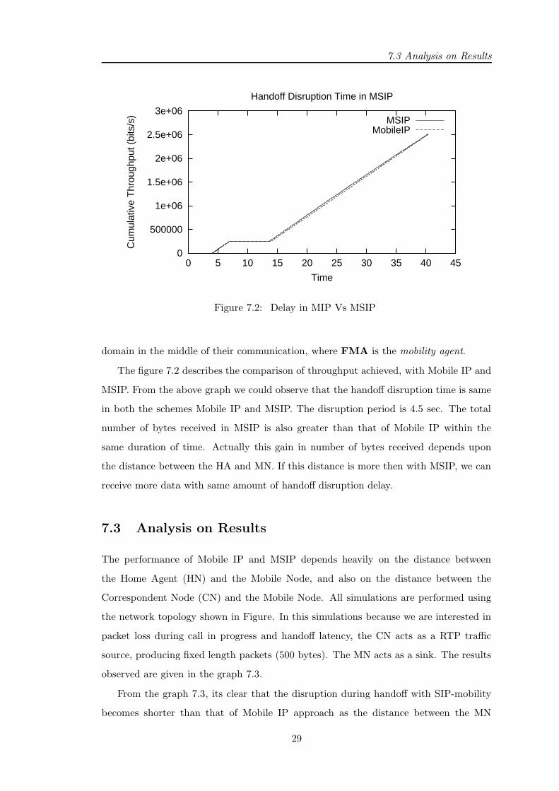
domain in the middle of their communication, where FMA is the mobility agent.
The figure 7.2 describes the comparison of throughput achieved, with Mobile IP and
MSIP. From the above graph we could observe that the handoff disruption time is same
in both the schemes Mobile IP and MSIP. The disruption period is 4.5 sec. The total
number of bytes received in MSIP is also greater than that of Mobile IP within the
same duration of time. Actually this gain in number of bytes received depends upon
the distance between the HA and MN. If this distance is more then with MSIP, we can
receive more data with same amount of handoff disruption delay.
7.3 Analysis on Results
The performance of Mobile IP and MSIP depends heavily on the distance between
the Home Agent (HN) and the Mobile Node, and also on the distance between the
Correspondent Node (CN) and the Mobile Node. All simulations are performed using
the network topology shown in Figure. In this simulations because we are interested in
packet loss during call in progress and handoff latency, the CN acts as a RTP traffic
source, producing fixed length packets (500 bytes). The MN acts as a sink. The results
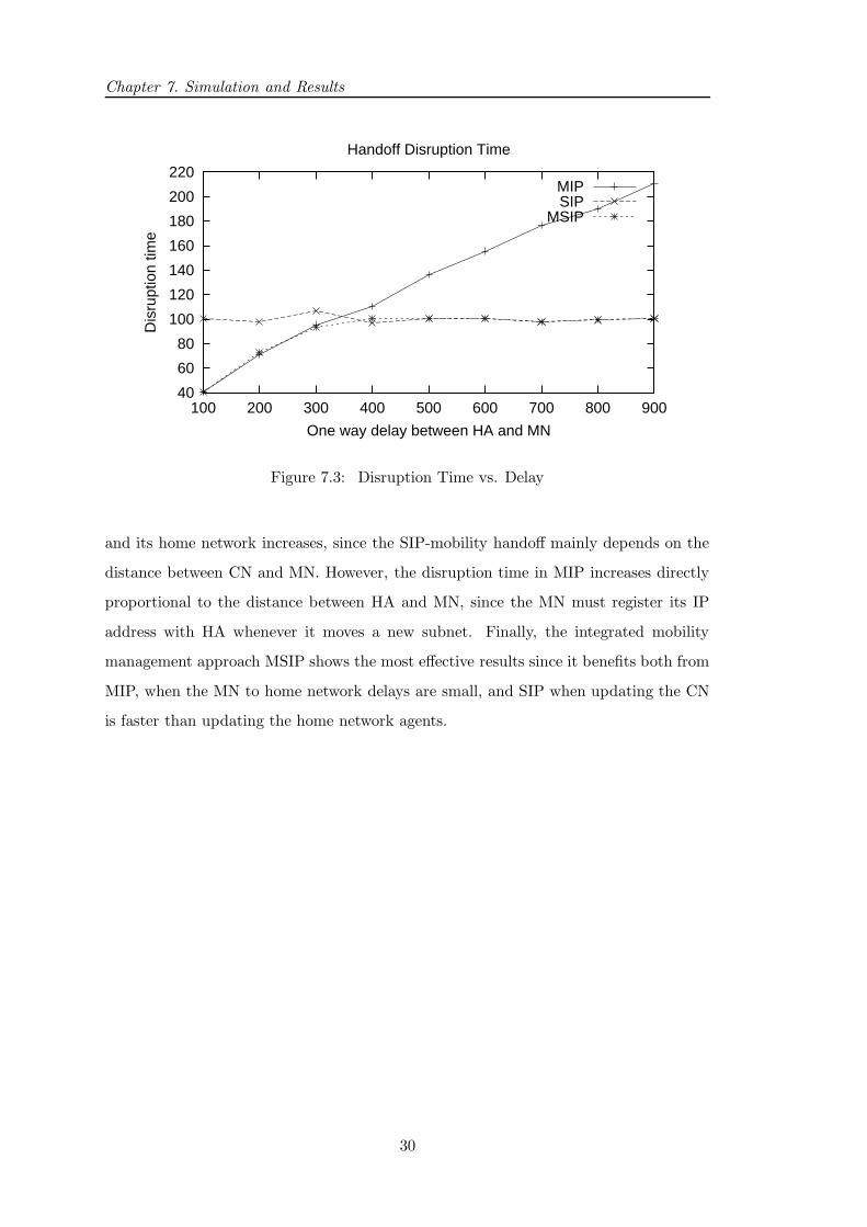
observed are given in the graph 7.3.
From the graph 7.3, its clear that the disruption during handoff with SIP-mobility
becomes shorter than that of Mobile IP approach as the distance between the MN
29
Chapter 7. Simulation and Results
40
60
80
100
120
140
160
180
200
220
100 200 300 400 500 600 700 800 900
Dis
rupt
ion
time
One way delay between HA and MN
Handoff Disruption Time
MIPSIP
MSIP
Figure 7.3: Disruption Time vs. Delay
and its home network increases, since the SIP-mobility handoff mainly depends on the
distance between CN and MN. However, the disruption time in MIP increases directly
proportional to the distance between HA and MN, since the MN must register its IP
address with HA whenever it moves a new subnet. Finally, the integrated mobility
management approach MSIP shows the most effective results since it benefits both from
MIP, when the MN to home network delays are small, and SIP when updating the CN
is faster than updating the home network agents.
30
Chapter 8
Future Work and Conclusions
MSIP performs better than Mobile IP and SIP. The better performance here means
a lesser handoff delay. In our hybrid scheme it takes lesser time, for the first packet
(after the handoff), of the ongoing communication, to reach the MN. There are some
issues yet to be resolved in this scheme, like authentication. Experiments need to be
done, to measure these authentication delays, required for exchange of extra control
messages (Extra, because, in our scheme, control messages of both Mobile IP and SIP
are involved).
The delay involved in obtaining a new IP address from a DHCP server mainly depends on
its implementation. The duration of the hand-off period would be significantly reduced
if the mobile host could immediately begin using the new IP address while verifying in
the background that it is not in use by any other host. In addition, the accuracy and
speed of determining when handoff is necessary could be increased
31

Chapter 8. Future Work and Conclusions
32
Bibliography
[1] C. Perkins, Network Working Group, RFC 3220: IP Mobility Support for IPv4,
http://www.ietf.org/rfc/rfc3220.txt.
[2] D. B. Johnson and Charles Perkins, ”Route Optimization in Mobile IP”, Internet
Draft, Internet Engineering Task Force, 1996.
[3] Charles Perkins, ”IP encapsulation within IP”, Request for Comments (Proposed
Standard) 2003, Internet Engineering Task Force , 1996.
[4] Amir Mahajan Ben, ”Route Optimizations In Mobile IP”, cite-
seer.ist.psu.edu/570186.html
[5] Jon-Olov Vatn, ”Long Random Wait Times for Getting a Care-of Address are a Dan-
ger to Mobile Multimedia”, International Workshop on Mobile Multimedia Commu-
nications, ”MoMuC 99”, November 1999.
[6] Elin Wedlund and Henning Schulzrinne, ”Mobility Support Using SIP”, ”WOW-
MOM”, 1999.
[7] M. Handley and H. Schulzrinne and E. Schooler, ”SIP: Session initiation protocol”,
Internet Draft, Internet Engineering Task Force, July 1997. Work in progress., 1997.
[8] G. Ayorkor Mills-Tettey and David Kotz, ”Mobile Voice over IP (MVOIP): An
Application-Level Protocol”, citeseer.ist.psu.edu/571001.html
[9] http://dns.antd.nist.gov/proj/iptel/
[10] Xinhua Zhao and Claude Castelluccia and Mary Baker, ”Flexible Net-
work Support for Mobility”, Mobile Computing and Networking, 1998, cite-
seer.ist.psu.edu/zhao98flexible.html
33
BIBLIOGRAPHY
[11] S. Giordano, M. Mancino, A. Martucci and S. Niccolini, ”Managing Multimedia
Traffic in IP Integrated over Differentiated Services: SIP dynamic signaling inter-
working”, 36th Annual Hawaii International Conference on System Sciences, 2003.
[12] A. Dutta, F. Vakil, J.-C. Chen, M. Tauil, S. Baba, N. Nakajima, H. Schulzrinne,
”Application Layer Mobility Management Scheme for Wireless Internet”, 3G Wire-
less 2001, May 2001, pp. 7.
[13] Nilanjan Banerjee, Wei Wu, Sajal K. Das, Spencer Dawkins and Jogen Pathak,
”Mobility Support in Wireless Internet”, IEEE Wireless Communications, 2003,
October 2003.
[14] Charles E. Perkins, Pravin Bhagwat, Highly dynamic Destination-Sequenced
Distance-Vector routing (DSDV) for mobile computers, ACM SIGCOMM Computer
Communication Review, v.24 n.4, p.234-244, Oct. 1994.
[15] The VINT project, NS notes and documentation, editors: Kevin Fall and Kan-
nan Varadhan, http://www.isi.edu/nsnam/ns.
34