MSHA Handbook Series - Mine Safety and Health … Handbook Series U.S. Department of Labor Mine...
81
MSHA Handbook Series U.S. Department of Labor Mine Safety and Health Administration Coal Mine Safety and Health December 2013 Handbook Number PH13-V-4 ROOF CONTROL PLAN APPROVAL AND REVIEW PROCEDURES
-
Upload
duongkhuong -
Category
Documents
-
view
230 -
download
0
Transcript of MSHA Handbook Series - Mine Safety and Health … Handbook Series U.S. Department of Labor Mine...
MSHA Handbook Series U.S. Department of Labor
Mine Safety and Health Administration
Coal Mine Safety and Health
December 2013
Handbook Number PH13-V-4
ROOF CONTROL PLAN APPROVAL
AND REVIEW PROCEDURES
PREFACE
This handbook establishes guidelines and procedures for CMS&H personnel to follow when
evaluating and processing roof control plans and/or roof control plan revisions. The guidelines
and instructions in this handbook address procedural, administrative, and technical aspects of
plan reviews, and are intended to serve as organizational and technical aids for roof control Plan
Reviewers. Guidance for conducting inspection activity can be found in the CMS&H General
Inspection Procedures Handbook.
Kevin G. Stricklin Date
Administrator for
Coal Mine Safety and Health
Handbook Number PH13-V-4
ROOF CONTROL PLAN APPROVAL and REVIEW PROCEDURES
Table of Contents
Chapter 1Introduction
A. Purpose and General Requirements of Roof Control Plans 3
B. Authority 3
C. Responsibility 3
Chapter 2Management System Controls 4
Chapter 3Plan Reviews 7
Chapter 4Reviews of Plan Revisions 10
Chapter 5Quarterly Reviews 11
Chapter 6Six Month Reviews 12
APPENDICES
A. Roof Control Sample Standard Operating Procedures(SOP) with Plan Transmittal Sheet
B. Checklists for Use in Plan Reviews
C. Approval of Complex and/or Non-Typical Roof Control Plans and Revisions (Addendums)
D. Guidelines for Conducting Pillar Stability Analyses
E. Precautions for the Use of the National Institute for Occupational Safety and Health
(NIOSH) Pillar Analysis Computer Programs
F. General Guidelines for the Use of Numerical Modeling to Evaluate Ground Control Aspects
of Proposed Coal Mining Plans
G. Pillar Recovery Design, Technologies, and Procedures in Roof Control Plan Reviews
H. Guidelines for Geotechnical Assessments Prior to Retreat Mining
I. Guidelines for Evaluating a Mine’s Historical Record (roof falls, injuries, bursts, accident
reports, citations, and past review forms)
J. Underground Inspections For Onsite Roof Control Plan Approvals and Plan Review
K. Tensioned Cable Bolts
L. Best Practices for Turning Crosscuts with Remote Controlled Continuous Mining Machines
M. Use of Mobile Roof Support (MRS) Units for Retreat Mining
N. Essential Elements of a Roof Fall Accident Investigation
O. Protecting Miners from Hazards Related to Rib Falls
ROOF CONTROL PLAN APPROVAL CHAPTER 1 AND REVIEW PROCEDURES
December 2013 - 1 -
Chapter 1
INTRODUCTION
A. Purpose and General Requirements of Roof Control Plans
A sound roof control plan is essential for controlling the roof, face and ribs, including coal or
rock bursts in underground coal mines. Each mine operator is required by 30 CFR 75.220 (a) (1)
to develop and follow a roof control plan, approved by the Mine Safety and Health
Administration (MSHA) District Manager, that is suitable to the prevailing geological
conditions, and the mining system to be used at the mine. Additional measures must be taken to
protect persons if unusual hazards exist. Section 75.220 (a) (2) requires that an operator must
submit a proposed plan and any revisions to the District Manager in writing. Under section
75.220 (c), no proposed roof control plan or revision to a roof control plan shall be implemented
before it is approved by the District Manager.
A good roof control plan includes information and criteria that supervisors and miners need to be
aware of to maintain effective roof control in their working environment. Section 75.221
specifies information that must be included in each roof control plan. Section 75.222 sets forth
the criteria that must be considered on a mine-by-mine basis in the formulation and approval of
plans and revisions. Additional measures may be required by the District Manager to suit the
particular conditions at the mine.
B. Authority
Title 30 CFR 75.220 – 75.223.
C. Responsibility
Only the District Manager or those designated as acting in the District Manager’s absence have
the authority to approve or disapprove roof control plans.
D. Directives Affected
This handbook incorporates and supersedes the following MSHA Directives:
1. Program Information Bulletin No. P10-23 Precautions for the Use of the Analysis of
Retreat Mining Pillar Stability (ARMPS) Computer Program, Dated 12/27/2010
2. Program Information Bulletin No. P09-03 General Guidelines for the Use of Numerical
Modeling to Evaluate Ground Control Aspects of Proposed Coal Mining Plans, Dated
3/16/2009
3. Procedure Instruction Letter No. I12-V-02 Pillar Recovery Design, Technologies, and
Procedures in Roof Control Plan Reviews, Dated 2/16/2012
4. Procedure Instruction Letter I12-V-15 Tensioned Cable Bolts, Dated 5/7/2012
5. Program Information Bulletin No. P11-33 Best Practices for Turning Crosscuts with
Remote Controlled Continuous Mining Machines, Dated 5/6/2011
ROOF CONTROL PLAN APPROVAL CHAPTER 1 AND REVIEW PROCEDURES
December 2013 - 2 -
6. Program Information Bulletin No. P11-30 Use of Mobile Roof Support (MRS) Units for
Retreat Mining, Dated 4/27/2011
7. Program Information Bulletin No. P11-29 Protecting Miners from Hazards Related to Rib
Falls, Dated 4/21/2011
ROOF CONTROL PLAN APPROVAL CHAPTER 2 AND REVIEW PROCEDURES
December 2013 - 3 -
Chapter 2
MANAGEMENT SYSTEM CONTROLS
A proposed roof control plan, and any revisions to the plan, must be submitted in writing to the
District Manager. All requests for approval of roof control plans and/or revisions should be
submitted to the District Office. A District Manager that desires an arrangement for mine
operators to submit plans to other locations, e.g., a Coal Mine Safety and Health Field Office,
should obtain approval for these other locations from the Administrator of Coal Mine Safety and
Health.
A Mine Plan Approval System (MPAS) is in place in each MSHA District Office. This system
is a database application that tracks plan approvals and reviews. Each District Office should log
all plan submittals into the MPAS and assign a tracking number to the plan. Other data that must
be entered into the system include the date a plan was received and the mine identification
number.
Each MSHA District Office should use the MPAS to track an operator’s response to a District
Manager’s request for plan revisions, and to identify overdue responses.
A plan request should be handled efficiently with an effort to complete the process in a time
period of 45 calendar days. If more than 45 days is required, then the reasons for the extra time
should be documented in the comments section on the plan transmittal sheet.
When MSHA formally requests additional information from a mine operator in order to make a
decision, the request date for the additional information should be recorded in the MPAS. If the
operator fails to respond to this request, MSHA should ask the operator to withdraw the plan via
letter, e-mail or fax and the withdrawal action should be documented in the MPAS. If the
operator refuses or does not respond in a timely manner, the plan should be disapproved and a
letter sent to the mine operator explaining the rationale for the decision. If the mine operator
withdraws its plan and submits a new plan, the new plan should be documented in the MPAS.
Only those persons designated by the Roof Control Supervisor, Assistant District Manager
(ADM) or District Manager may contact the operator for additional information.
The progress of the plan and/or revision through the approval process should be coordinated by
the ADM following the district’s Standard Operating Procedure (SOP) and Plan Transmittal
Sheet. A sample SOP, together with the Plan Transmittal Sheet, is provided in Appendix A. The
content of the District Roof Control SOPs must conform to the elements provided in the sample
SOP and should not contain any policies or procedures. After the submittal has been entered into
the MPAS and a tracking number has been assigned, the following sequence of events should
occur. It is recognized that many changes or revisions are proposed that address specific
portions of the approved plan. Therefore, all the following steps may not be necessary in all
situations. The ADM may expedite the review process where the nature of the revision warrants
in that case.
ROOF CONTROL PLAN APPROVAL CHAPTER 2 AND REVIEW PROCEDURES
December 2013 - 4 -
1. The original submittal and Plan Transmittal Sheet should be given to the Roof Control
Supervisor. He/she assigns the plan to the Plan Reviewer.
2. After receiving the plan and/or revision from the Roof Control Supervisor, the Reviewer
conducts a thorough review in accordance with the Chapters 3-6 of the MSHA Roof
Control Plan Approval and Review Handbook.
3. The Reviewer uses the Plan Transmittal Sheet to document the plan coordination and
review, together with his or her recommendations and any relevant comments. The
Reviewer then returns the review to the Roof Control Supervisor.
4. The Roof Control Supervisor documents his or her recommendations, along with any
relevant comments, on the Plan Transmittal Sheet, and then forwards the plan to the
ADM.
5. The ADM documents his or her recommendations, along with any relevant comments, on
the Plan Transmittal Sheet, and forwards the plan to the District Manager.
The District Manager must notify the operator in writing whether the proposed plan is approved
or denied.
1. If the District Manager approves the proposed plan or revision, written notification is sent
to the operator stating that the roof control plan is approved.
2. If the District Manager determines that the proposed plan or revision is not suitable to the
prevailing geological conditions or the system of mining to be used at the mine, written
notification is sent to the operator that (1) addresses the deficiencies of the proposed plan
or revision for which approval is denied; (2) provides the operator an opportunity to
discuss with the District Manager the problems identified and potential solutions; and (3)
sets a reasonable time for the operator to submit any revised plan provisions, if needed.
If the deficiencies are corrected, approval correspondence is prepared. If provision(s)
cannot be approved, MSHA procedures established in the Program Policy Manual,
Volume V, V.G-4 apply.
Once the District Manager signs the approval or denial letter, the complete plan (submittal), and
the approval or denial letter, are mailed to the mine operator.
The date the review was completed and the date the District Manager signed the letter of
approval or denial is entered into the MPAS.
One copy of the completed approved plan and/or revision (with approval letter) is sent to the
MSHA Coal Mine Safety and Health Field Office and placed in the Uniform Mine File. This
copy should be sent at the same time that the approval letter is sent to the operator. If
appropriate, copies of the approved plan (with approval letter) should also be sent to the
appropriate state agency and the miners’ representative. Copies of denied or withdrawn plans
are not required to be sent to the field office. If a plan is withdrawn by the operator, that fact
should be documented in the MPAS.
One copy of the completed approved plan with the approval letter should be retained at the
District Office. This file should also include all documentation of the plan reviews and
ROOF CONTROL PLAN APPROVAL CHAPTER 2 AND REVIEW PROCEDURES
December 2013 - 5 -
evaluations (including MSHA Form 2000-204 (if applicable), checklists, drawings, sketches,
correspondence between the operators and Plan Reviewers, etc.) that support the decision to
approve the plan. This file should be retained by the District for at least as long as the plan is in
effect. Documentation for plans for which approval is denied or for plans that are withdrawn by
the operator is not required to be retained.
In accordance with Section 75.223 (d), MSHA must review all roof control plans every six
months. The date on which the initial plan is approved becomes the date of record for that plan.
The first six month review must be completed within six months of the date of record for the
plan. All subsequent six month reviews are completed within six months of the date of the last
completed review. If the operator revises and resubmits a previously approved plan, and the
resubmittal is approved, then the new approval date becomes the date of record for the plan.
ROOF CONTROL PLAN APPROVAL CHAPTER 3 AND REVIEW PROCEDURES
December 2013 - 6 -
Chapter 3
PLAN REVIEWS
While responding promptly to each request for a roof control plan approval is important, review
quality and thoroughness are essential. MSHA has established explicit criteria and guidance for
assessing the quality of, and potential safety risk associated with, proposed plans. Districts are
required to document the basis for their conclusion that approved plans will provide effective
roof control.
The Roof Control Supervisor or Specialist will review the plan as follows:
1. In considering whether to approve a proposed plan, the Reviewer must determine
whether the plan is consistent with all relevant, mandatory provisions of the Mine Act
and MSHA’s standards and regulations.
2. If the operator is resubmitting a previously approved plan, then the Reviewer should
ensure that it maintains at least the same level of protection for the miners as the
previously approved plan. Any significant additions, deletions, or changes must be
noted.
3. The Reviewer determines that all required information has been submitted.
4. The Reviewer contacts the assigned CMI and/or Field Office Supervisor to
solicit comments on the appropriateness of the plan. The Reviewer documents
any comments by the CMI and Field Office Supervisor on the Plan Transmittal
Sheet.
5. The Reviewer considers written comments from the representatives of miners and
documents whether comments were received on the Plan Transmittal Sheet.
6. If the mine operator submits written correspondence (including e-mail), it should be
printed and retained with the official file. Significant interactions, such as meetings with
the operators, should also be documented.
7. If the plan under review is for an existing mine, the Reviewer checks the mine
files for information relating to plan adequacy including roof fall history, injury
experience, accident reports, , citations, and plan review (MSHA Form 2000-
204) forms from the mine. Appendix I contains guidance for evaluating a
mine’s historical record.
8. Based on the type of plan submittal and the complexity of the mine, the Reviewer
determines whether MSHA’s Directorate of Technical Support (Technical Support) Roof
Control Division’s assistance with the review of the plan is warranted. Appendix C,
“Approval of Complex and/or Non-Typical Roof Control Plans and Addendums,” is used
to assist in determining which plans should be forwarded to Technical Support.
ROOF CONTROL PLAN APPROVAL CHAPTER 3 AND REVIEW PROCEDURES
December 2013 - 7 -
When a plan submittal, or any portion thereof, is forwarded by the District Office to
Technical Support for assistance with the review, the District Office records the
transmittal in the comments section of the MPAS district level data entry screen. This
record should include the date and pertinent information regarding the plan that was sent
to Technical Support as well as the date and summary of the Technical Support
recommendations.
9. If Technical Support’s assistance is not requested with a plan, then the Reviewer uses
Analysis of Retreat Mining Pillar Stability (ARMPS), Analysis of Longwall Pillar
Stability (ALPS), Analysis of Multiple Seam Stability (AMSS) or other applicable
software for development and/or retreat pillar stability analysis. Critical input parameters
and calculations sent by an operator are verified by the Roof Control Specialist (or
Reviewer) as part of the review. The necessary input parameters (depth of cover,
projected pillar centers, mining heights, interburden thicknesses, etc.) may be obtained
from the 30 CFR 75.372 ventilation map, the 30 CFR 75.1200 mine map, or other
documented sources. If necessary, the District Manager should exercise his authority
under 30 CFR 75.1203 to require an operator to furnish a current 30 CFR 75.1200 mine
map with depth of cover contours (or surface topography and seam elevation contours).
Appendix D contains guidance for conducting pillar stability analyses. If MSHA’s
evaluation shows that the stability factors calculated do not meet or exceed the design
criteria in the appropriate NIOSH software program listed in Appendix E, “Precautions
for the Use of the National Institute for Occupational Safety and Health (NIOSH) Pillar
Analysis Computer Programs,” or do not meet or exceed minimum safety criteria for
other computer models used, see Appendix F, “General Guidelines for the Use of
Numerical Modeling to Evaluate Ground Control Aspects of Proposed Coal Mining
Plans” then the proposed roof control plan is forwarded to Technical Support for
assistance in accordance with Appendix C.
10. The Reviewer communicates with other plan approval groups concerning common issues
in a plan. The Reviewer consults with the Ventilation Group and reviews overlay and
underlay maps of coal mine workings above and below projected mining. The Reviewer
should pay particular attention to evaluating the possible presence of impounded water
above projected mining. If the Reviewer determines that such impoundments may exist,
a permit may be required in accordance with 30 CFR 1716-2.
11. MSHA has created roof control plan checklists to assist the Reviewer in reviewing plans,
and to document the rationale supporting plan approvals. MSHA’s mandatory standards,
interpretive guidance, safety precautions and best practices are included in the checklists.
The checklists are not intended to be a “one size fits all” approach because roof control
plans are developed and revised on a mine-by-mine basis considering the prevailing
geological conditions and the mining system to be used at the mine. Consequently, not
all items on the checklists are always applicable for each and every mine. If an item on
any of the checklists is not applicable during a review, the Reviewer should mark the
item “N/A.” The checklists are contained in Appendix B. Other Appendices provide
additional information that can aid the Reviewer in determining which checklist items
may be appropriate on a mine-by-mine basis. Specifically, retreat mining is addressed in
ROOF CONTROL PLAN APPROVAL CHAPTER 3 AND REVIEW PROCEDURES
December 2013 - 8 -
Appendices G and H, mobile roof supports are addressed in Appendix M, rib control is
addressed in Appendix O, turning crosscuts is addressed in Appendix L, and tensioned
cable bolts are addressed in Appendix K.
12. If applicable, the Specialist, Roof Control Supervisor, Field Office Supervisor, Coal Mine
Inspector (CMI) or Technical Support conducts a limited inspection of the mine and
evaluates the suitability of the plan to the roof and rib conditions. The results of the
evaluation should be discussed with the operator and any miners' representatives.
Guidance for conducting underground inspections for a roof control plan approval or
review is contained in Appendix J.
13. The Roof Control Group determines whether an on-site evaluation should be conducted
at a new highwall and/or pre-existing highwall that is developed as a portal area for new
underground mine openings.
14. The Reviewer should evaluate all plan requests for making extended cuts with remote
controlled continuous mining machines in accordance with MSHA PIL “Procedures for
Evaluation of Requests to Make Extended Cuts With Remote Controlled Continuous
Mining Machines,” available at http://www.msha.gov/regs/complian/PILS/2012/PIL12-
V-11.asp.
Upon completion of the review, the Reviewer makes a recommendation as to whether the
plan should be approved, and marks the appropriate box on the Plan Transmittal Sheet.
Following his or her review, the Roof Control Supervisor and the ADM review the Plan
Reviewer’s recommendation, and note their own recommendations on the Transmittal Sheet.
ROOF CONTROL PLAN APPROVAL CHAPTER 4 AND REVIEW PROCEDURES
December 2013 - 9 -
Chapter 4
REVIEWS OF PLAN REVISIONS
The procedures for reviewing plan revisions (addendums) are similar to those for reviewing
plans. The key difference is that most proposed plan revisions only address specific portions of
the approved plan. Therefore, some steps in Chapter 3 may be unnecessary in some situations.
In particular, depending on the nature of the revision only some of the checklists may be
appropriate (Chapter 3, section 11). The Roof Control Supervisor should make the
determination as to which checklists should be used for each revision.
A revision of the roof control plan is not necessarily required each time that equipment is added.
However, a revision is necessary when there is a significant change to the mining system.
Significant changes include the addition of a roof bolter with a different roof bolt installation
pattern or a different type of Automated Temporary Roof Support (ATRS) system, new mining
equipment that would require a change to the depth of an extended cut or pillar lift depth (e.g.,
center drive shuttle car or continuous mining machine (CM) with deck), a change from shuttle
cars to continuous haulage, or adding a roof bolter with rib bolting capability.
In accordance with 30 CFR 75.220 (a) (2), when revisions are proposed, only the revised pages
need to be submitted unless otherwise specified by the District Manager. When the number of
revisions to an approved plan makes it difficult to determine the operative provisions of the plan,
the District Manager should notify the operator in writing to submit a revised plan that clearly
sets forth all previously approved revisions and any proposed revisions, and deletes those
provisions that are no longer applicable.
ROOF CONTROL PLAN APPROVAL CHAPTER 5 AND REVIEW PROCEDURES
December 2013 - 10 -
Chapter 5
QUARTERLY REVIEWS
Reviews of the roof control plans should be completed every quarter by a CMI to ensure that
the plans are suitable to current geological conditions and mining systems in the mine. The
CMI should use the MSHA Form 2000-204 to document the results of these reviews. If the
CMI indicates a deficiency on the MSHA Form 2000-204, then the form should be sent to the
District Roof Control Supervisor for evaluation.
After receiving the MSHA Form 2000-204, the District Roof Control Supervisor should
determine if a roof control plan deficiency exists. If a deficiency is determined, the District Roof
Control Supervisor should require the plan to be revised to address the deficiency.
The Roof Control Group should prepare correspondence for the District Manager’s signature that
(1) identifies the deficiencies of the plan; (2) provides the operator an opportunity to discuss with
the District Manager the problems identified and potential solutions; and (3) sets a reasonable
time for the operator to submit any revised plan provisions, if needed. If the deficiencies are
corrected, approval correspondence must be prepared. If provision(s) cannot be approved,
MSHA procedures established in the Program Policy Manual, Volume V, V.G-4 apply.
The District Roof Control Supervisor should notify the CMI who identified the deficiency and
the Field Office Supervisor of the corrective action taken and of the applicable plan changes, by
either memo or e-mail. If the District Roof Control supervisor determines that no deficiency
exists, he or she should notify CMI and Field Office Supervisor by memo or by e-mail. In either
case, a copy of the memo or e-mail should be attached to the MSHA Form 2000-204 and
included in the Uniform Mine File.
ROOF CONTROL PLAN APPROVAL CHAPTER 6 AND REVIEW PROCEDURES
December 2013 - 11 -
Chapter 6
SIX MONTH REVIEWS
In accordance with 30 CFR 75.223, the roof control plan must be reviewed every six months by
an Authorized Representative of the Secretary (AR). This requirement ensures that approved
plans are still appropriate for the mine and continue to provide an adequate system of roof
control and are revised as conditions warrant.
When the number of revisions (addendums) to the plan makes it difficult to determine the
operative provisions of the plan, the District Manager should notify the operator in writing to
submit a revised plan that incorporates all revisions in an orderly manner, and deletes those
provisions that are no longer applicable.
The regular CMI may conduct the six month reviews of the less complex or typical plans in the
District with assistance provided by the Roof Control Specialist as needed. A Roof Control
Specialist should conduct the six month reviews of the more complex or non-typical plans in the
District. Refer to Appendix C for additional guidance on complex or non-typical plans and
addendums. The following are the basic steps in the six month review:
Prior to the underground inspection, the following items should be reviewed by either the CMI or
the Roof Control Specialist:
Detailed historical record of safety conditions at the mine including roof fall
accident data, roof control citations, roof and rib fall injuries, roof falls, and coal
or rock outbursts for at least the prior six months (see Appendix I).
Previous MSHA Form 2000-204 comments.
The Reviewer communicates with other plan approval groups concerning common issues in a
plan. The Reviewer consults with the ventilation group reviewing overlay and underlay maps of
coal mine workings above and below projected mining. The Reviewer should ensure that the
possible presence of impounded water above projected mining are evaluated. If the Reviewer
determines that such impoundments may exist, a permit may be required in accordance with 30
CFR 75.1716-2.
The Reviewer should also evaluate mining projections using ARMPS, ALPS, AMSS, or other
applicable software for development and/or retreat pillar stability analysis. Appendix D contains
guidance on conducting pillar stability analyses. Critical input parameters and calculations sent
by an operator should be verified by the Reviewer. The necessary input parameters (depth of
cover, projected pillar centers, mining heights, interburden thicknesses, etc.) may be obtained
from the 30 CFR 75.372 ventilation map, the 30 CFR 75.1200 mine map, or other documented
sources. If necessary, the District Manager should exercise his or her authority under 30 CFR
75.1203 to require operators to furnish a current 30 CFR 75.1200 mine map with depth of cover
contours (or surface topography and seam elevation contours).
ROOF CONTROL PLAN APPROVAL CHAPTER 6 AND REVIEW PROCEDURES
December 2013 - 12 -
If MSHA’s evaluation shows that the stability factors calculated do not meet or exceed the
design criteria listed in the appropriate NIOSH software program listed in Appendix E,
“Precautions for the Use of the NIOSH Pillar Analysis Computer Programs”, or do not meet or
exceed minimum safety criteria for other computer models used, then the proposed mining
should be considered as “complex or non-typical” and the process described in Appendix C,
“Approval of Complex and/or Non-Typical Roof Control Plans and Addendums” should be
followed. If MSHA conducted a pillar stability analysis concurrently with the review of the
ventilation plan at any time during the six months prior to the roof control plan review, then the
Plan Reviewer may make the determination that it is not necessary to conduct another analysis,
but in every case the results of the pillar stability analysis should be documented.
If necessary, the Specialist, Roof Control Supervisor, Field Office Supervisor, CMI, or Technical
Support conducts a limited inspection of the mine and evaluates the roof and rib conditions. The
results of the evaluation should be discussed with the operator and any miners'
representatives. Guidance for conducting underground inspections for a roof control plan
approval or review is contained in Appendix J. The Roof Control Group should contact the
assigned CMI and/or Field Office Supervisor to solicit comments on the appropriateness of the
plan.
Following the inspection, a Plan Review form (MSHA Form 2000-204) should be completed by
the Authorized Representative of the Secretary or Roof Control Specialist who is conducting the
six month review. A brief narrative describing the adequacy or any deficiencies of the plan
should be included on the MSHA Form 2000-204. If the MSHA Form 2000-204 indicates a
deficiency or needed change, the form should be sent to the District Roof Control Supervisor for
evaluation.
For mines in a non-producing status, the CMI’s review, as recorded on MSHA Form 2000-204
may be used for computer input and review in the MPAS.
After completion of the six month review, if deficiencies in the plan are identified, the Roof
Control Supervisor or Specialist must prepare correspondence for the District Manager’s
signature that (1) informs the operator of the findings of the review and the need for revisions to
the approved plan; (2) provides an opportunity to discuss with the District Manager the
problems identified and potential solutions; and (3) sets a reasonable time for the operator to
submit any revised plan provisions, if needed. If the corrections will result in significant changes
to the plan, then the procedures in Chapter 4 on plan revisions apply. If the deficiencies are
corrected, approval correspondence must be prepared. If provision(s) cannot be approved,
MSHA procedures established in the Program Policy Manual, Volume V, V.G-4 apply. A copy
of the deficiency letter and subsequent approval letter must be sent to the appropriate field office
and be included in the uniform mine file.
ROOF CONTROL PLAN APPROVAL APPENDIX A AND REVIEW PROCEDURES
December 2013 - 13 -
APPENDIX A
ROOF CONTROL SAMPLE STANDARD OPERATING PROCEDURES
WITH PLAN TRANSMITTAL SHEET
When any roof control plan and/or revision (addendum) of a roof control plan is received in the
District Office, (List title of person in the district who will complete this task) will log it into
the Mine Plan Approval System (MPAS) and assign a tracking number to the plan.
(List title of person in the district who will complete this task) will attach a Plan Transmittal
Sheet to the plan and complete all applicable sections.
(List title of person in the district who will complete this task) forwards the original plan and
Plan Transmittal Sheet to the Roof Control Supervisor.
Roof Control Supervisor assigns the plan and/or revision to the Plan Reviewer.
The Reviewer conducts a thorough review of plan in accordance with the Chapters 3-6 of the
MSHA Roof Control Plan Approval and Review Handbook.
The Reviewer uses the Plan Transmittal Sheet to document the plan coordination and review,
together with his or her recommendations and any relevant comments and then returns the
review to the Roof Control Supervisor.
The Roof Control Supervisor documents his or her recommendations, along with any relevant
comments, on the Plan Transmittal Sheet, and then forwards the plan to the Assistant District
Manager for Technical Services (ADM).
The ADM documents his or her recommendations, along with any relevant comments, on the
Plan Transmittal Sheet, and forwards the plan to the District Manager.
The District Manager must notify the operator in writing whether the proposed plan is approved
or denied. The notification will be conducted in accordance with the MSHA Roof Control Plan
Approval and Review Handbook.
Once the District Manager has signed the approval or denial letter, the complete plan (submittal),
and the approval or denial letter, are mailed to the mine operator by (List title of person in the
district who will complete this task).
The date the review was completed and the date the District Manager signed the letter of
approval or denial is entered into the MPAS by (List title of person in the district who will
complete this task).
One copy of the completed approved plan (with approval letter) is sent to the MSHA Coal Mine
Safety and Health Field Office at the same time that the plan is sent to the mine operator by (List
title of person in the district who will complete this task) and placed in the Uniform Mine File by
ROOF CONTROL PLAN APPROVAL APPENDIX A AND REVIEW PROCEDURES
December 2013 - 14 -
(List title of person in the district who will complete this task). If appropriate, copies of the
approved plan (with approval letter) should also be sent to the appropriate state agency and the
miners’ representative by (List title of person in the district who will complete this task). Copies
of denied or withdrawn plans are not required to be sent to the Field Office. If a plan is
withdrawn by the operator, that fact should be documented in the MPAS.
One copy of the completed approved plan and/or revision with the approval letter should be
retained at the District Office. This file should also include all documentation of the plan
reviews and evaluations (including MSHA Form 2000-204 (if applicable)), checklists, drawings,
sketches, correspondence between the coal operators and Plan Reviewers, etc.) that support the
decision to approve the plan. This file should be retained by the District for at least as long as
the plan is in effect. Documentation for plans for which approval is denied or for plans that are
withdrawn by the operator is not required to be retained.
Note: It is recognized that many changes or revisions are proposed that address specific portions
of the approved plan. Therefore, not all the above steps may be necessary in all situations. The
ADM may expedite the review process as necessary.
ROOF CONTROL PLAN APPROVAL APPENDIX A AND REVIEW PROCEDURES
December 2013 - 15 -
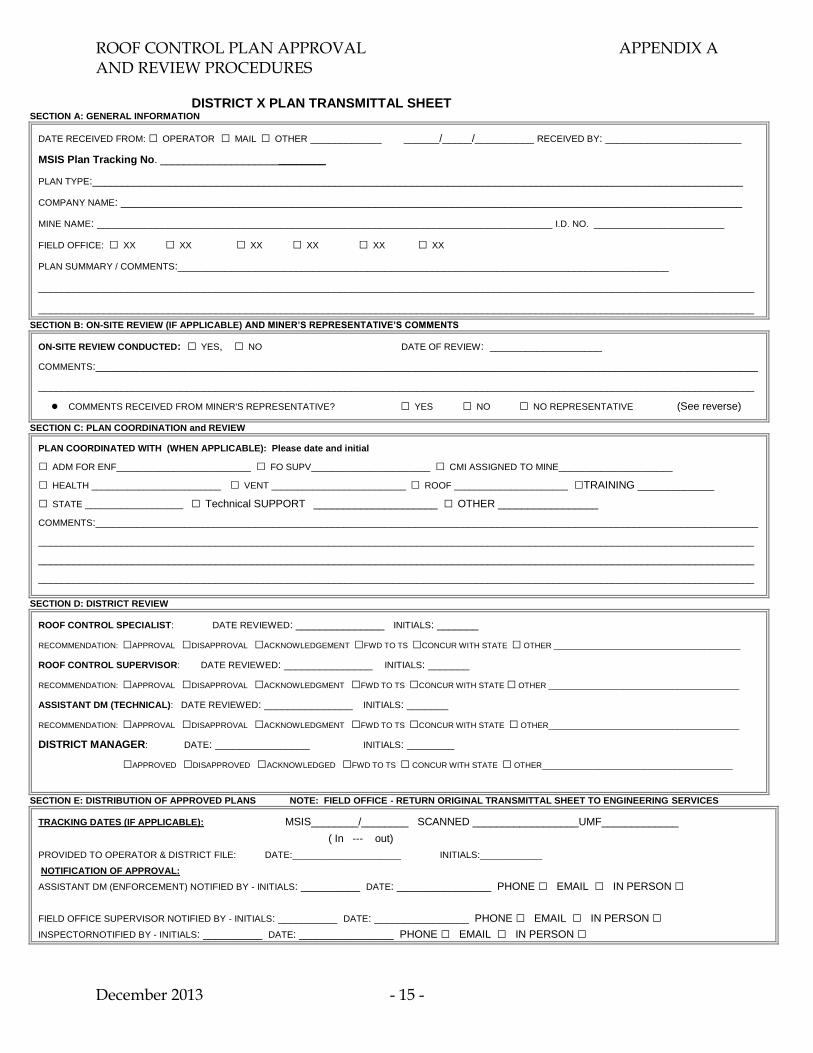
DISTRICT X PLAN TRANSMITTAL SHEET SECTION A: GENERAL INFORMATION
DATE RECEIVED FROM: □ OPERATOR □ MAIL □ OTHER ____________ ______/_____/__________ RECEIVED BY: _______________________
MSIS Plan Tracking No. ____________________________
PLAN TYPE:______________________________________________________________________________________________________________
COMPANY NAME: _________________________________________________________________________________________________________
MINE NAME: _____________________________________________________________________________ I.D. NO. ______________________
FIELD OFFICE: □ XX □ XX □ XX □ XX □ XX □ XX
PLAN SUMMARY / COMMENTS:___________________________________________________________________________________
_________________________________________________________________________________________________________________________
_________________________________________________________________________________________________________________________
SECTION B: ON-SITE REVIEW (IF APPLICABLE) AND MINER’S REPRESENTATIVE’S COMMENTS
ON-SITE REVIEW CONDUCTED: □ YES, □ NO DATE OF REVIEW: ___________________
COMMENTS:________________________________________________________________________________________________________________
_________________________________________________________________________________________________________________________
COMMENTS RECEIVED FROM MINER'S REPRESENTATIVE? □ YES □ NO □ NO REPRESENTATIVE (See reverse)
SECTION C: PLAN COORDINATION and REVIEW
PLAN COORDINATED WITH (WHEN APPLICABLE): Please date and initial
□ ADM FOR ENF__________________________ □ FO SUPV_______________________ □ CMI ASSIGNED TO MINE______________________
□ HEALTH _________________________ □ VENT __________________________ □ ROOF ______________________ □TRAINING _____________
□ STATE ___________________ □ Technical SUPPORT _____________________ □ OTHER _________________
COMMENTS:________________________________________________________________________________________________________________
_________________________________________________________________________________________________________________________
_________________________________________________________________________________________________________________________
_________________________________________________________________________________________________________________________
SECTION D: DISTRICT REVIEW
ROOF CONTROL SPECIALIST: DATE REVIEWED: _______________ INITIALS: _______
RECOMMENDATION: □APPROVAL □DISAPPROVAL □ACKNOWLEDGEMENT □FWD TO TS □CONCUR WITH STATE □ OTHER __________________________________________
ROOF CONTROL SUPERVISOR: DATE REVIEWED: _______________ INITIALS: _______
RECOMMENDATION: □APPROVAL □DISAPPROVAL □ACKNOWLEDGMENT □FWD TO TS □CONCUR WITH STATE □ OTHER ___________________________________________
ASSISTANT DM (TECHNICAL): DATE REVIEWED: _______________ INITIALS: _______
RECOMMENDATION: □APPROVAL □DISAPPROVAL □ACKNOWLEDGMENT □FWD TO TS □CONCUR WITH STATE □ OTHER___________________________________________
DISTRICT MANAGER: DATE: ________________ INITIALS: ________
□APPROVED □DISAPPROVED □ACKNOWLEDGED □FWD TO TS □ CONCUR WITH STATE □ OTHER___________________________________________
SECTION E: DISTRIBUTION OF APPROVED PLANS NOTE: FIELD OFFICE - RETURN ORIGINAL TRANSMITTAL SHEET TO ENGINEERING SERVICES
TRACKING DATES (IF APPLICABLE): MSIS________/________ SCANNED __________________UMF_____________
( In --- out)
PROVIDED TO OPERATOR & DISTRICT FILE: DATE:_____________________ INITIALS:____________
NOTIFICATION OF APPROVAL:
ASSISTANT DM (ENFORCEMENT) NOTIFIED BY - INITIALS: __________ DATE: ________________ PHONE □ EMAIL □ IN PERSON □
FIELD OFFICE SUPERVISOR NOTIFIED BY - INITIALS: __________ DATE: ________________ PHONE □ EMAIL □ IN PERSON □
INSPECTORNOTIFIED BY - INITIALS: __________ DATE: ________________ PHONE □ EMAIL □ IN PERSON □
ROOF CONTROL PLAN APPROVAL APPENDIX A AND REVIEW PROCEDURES
December 2013 - 16 -
COMMENTS: _________________________________________________________________________________________________________
_________________________________________________________________________________________________________
_________________________________________________________________________________________________________
_________________________________________________________________________________________________________
_________________________________________________________________________________________________________
_________________________________________________________________________________________________________
_________________________________________________________________________________________________________
_________________________________________________________________________________________________________
_________________________________________________________________________________________________________
_________________________________________________________________________________________________________
_________________________________________________________________________________________________________
_________________________________________________________________________________________________________
_________________________________________________________________________________________________________
_________________________________________________________________________________________________________
_________________________________________________________________________________________________________
_________________________________________________________________________________________________________
_________________________________________________________________________________________________________
_________________________________________________________________________________________________________
_________________________________________________________________________________________________________
_________________________________________________________________________________________________________
_________________________________________________________________________________________________________
_________________________________________________________________________________________________________
_________________________________________________________________________________________________________
_________________________________________________________________________________________________________
_________________________________________________________________________________________________________
_________________________________________________________________________________________________________
_________________________________________________________________________________________________________
_________________________________________________________________________________________________________
ROOF CONTROL PLAN APPROVAL APPENDIX B AND REVIEW PROCEDURES
December 2013 - 17 -
APPENDIX B
CHECKLISTS FOR USE IN PLAN REVIEWS
Roof Control Plan Review Preliminary Items (For six-month reviews and reviews of
resubmittals of previously approved plans)
New Mine Openings
General Plan Information
Mine Layout
General Roof Support
Tensioned Roof Bolts
Resin Grouted Roof Bolts
Supplemental Support
Mining Equipment
Extended Cuts
Pillar Retreat Mining
Mine-Specific Mobile Roof Support Units
Longwall Mining
ROOF CONTROL PLAN APPROVAL APPENDIX B AND REVIEW PROCEDURES
December 2013 - 18 -
ROOF CONTROL PLAN REVIEW PRELIMINARY ITEMS (For six-month reviews and reviews of resubmittals of previously approved
plans):
Review the detailed historical record of safety conditions at the mine for at least the prior six
months, including:
Accident data,
Roof control citations,
Roof and rib injuries, and
Non-injury roof falls and bursts.
Review comments made on previous MSHA Forms 2000-204.
Review comments from field personnel.
(If comments/recommendations from the field personnel will not be incorporated, notify that
person(s) of your reasoning for not incorporating the comments/recommendations.)

ROOF CONTROL PLAN APPROVAL APPENDIX B AND REVIEW PROCEDURES
December 2013 - 19 -
NEW MINE OPENINGS AND PUNCHOUTS
Mandatory Standards
30 CFR 75.221 (a) states that the following information shall be in each roof control
plan.
(11) The roof control plan shall include a description of the method of protecting
persons-
(i) From falling material at drift openings; and
(ii) When mining approaches within 150 feet of an outcrop.
The following items should be addressed in the roof control plan on a mine by-mine basis:
An on-site evaluation should be conducted at a new drift or slope mine by a roof control
specialist to evaluate the highwall and determine a minimum roof control plan for
development.
Prior to a punchout, an on-site evaluation should be conducted by a CMI or Roof Control
Specialist to evaluate the highwall.
The initial development plan should apply to at least the first 150 feet of development
from the highwall, and any subsequent time that mining approaches within 150 ft of the outcrop. It
should consist of the following at a minimum:
Roof bolt type and minimum length
Maximum roof bolt spacing
Maximum crosscut and entry widths
Minimum crosscut and entry centers
The roof control plan should address the following items on a mine-by-mine basis. An
evaluation should consist of determining whether the criteria is needed at a specific mine.
All unstable material shall be removed from the highwall above intended mine openings
and areas between openings where miners travel or are required to perform work.
A substantially constructed canopy shall be installed at all intended drift or slope
openings before penetrating the coal seam from a highwall. Canopies shall also be
installed at any other drift or slope openings in highwalls prior to being used by workers
to enter or exit the mine. The canopy shall be substantially constructed and extend from
the highwall for a distance which will provide for adequate protection from falling
highwall material.
ROOF CONTROL PLAN APPROVAL APPENDIX B AND REVIEW PROCEDURES
December 2013 - 20 -
GENERAL INFORMATION FOR PLAN REVIEW Mandatory Standards
30 CFR 75.221 (a) states that the following information shall be in each roof control
plan.
(1) The name and address of the company.
(2) The name, address, mine identification number and location of the mine.
(3) The name and title of the company official responsible for the plan.
(4) A typical columnar section of the mine strata which shall—
(i) Show the name and the thickness of the coalbed to be mined and any
persistent partings;
(ii) Identify the type and show the thickness of each stratum up
to and including the main roof above the coalbed and for
distance of at least 10 feet below the coalbed;
(iii) Indicate the maximum cover over the area to be mined.
30 CFR 75.221 (b) Each drawing submitted with a roof control plan shall
contain a legend explaining all symbols used and shall specify the scale of the
drawing which shall not be less than 5 feet to the inch or more than 20 feet to the
inch.
30 CFR 75.221 (c) All roof control plan information, including drawings,
shall be submitted on 8½ by 11 inch paper, or paper folded to this size.
Note: Keep the plan as concise and simple as possible by eliminating all unnecessary
material - especially material that restates the regulations. Note: The pages in the plan must be numbered sequentially.
(Note: Regarding Section 75.221(a) (4) (ii) where possible, a geologic log from an exploration
borehole located near the active mining area should be provided)
ROOF CONTROL PLAN APPROVAL APPENDIX B AND REVIEW PROCEDURES
December 2013 - 21 -
MINE LAYOUT
Mandatory Standards
30 CFR 75.203 (a) provides that “[p]illar dimensions shall be compatible with effective
control of the roof, face and ribs and coal or rock bursts.”
30 CFR 75.221 (a) (8) provides that the plan shall contain “[d]rawings indicating the
planned width of openings, [and] size of pillars….”
30 CFR 75.222 (b) (3) and (4) (i) and (ii) state that “[a]ny opening that is more than 20
feet wide should be supported by a combination of roof bolts and conventional supports”
and that “[p]osts should be installed to limit each roadway to 16 feet wide where straight
and 18 feet wide where curved; and a row of posts should be set for each 5 feet of space
between the roadway posts and the ribs.”
30 CFR 75.222 (b) (5) states that “[o]penings should never be more than 30 feet wide.”
(Section 75.221(a)(8) which requires drawings indicating the method of pillar recovery
and the sequence of mining pillars is discussed in another checklist included in this
Appendix.)
The following items should be addressed in the roof control plan on a mine by-mine basis:
Pillar dimensions should be specific dimensions instead of ranges. For example, specify
"Pillar dimensions in mains and submains will be 80 feet wide by 120 feet long" instead
of "Pillar width = 50 to 120 feet and pillar length = 80 to 140 feet." Mines that do use a
range of pillar sizes should incorporate a pillar stability factor. For example, “pillar
dimensions will be such that the calculated ARMPS stability factors will meet NIOSH
criteria at all times.”
A brief description of the pillar design analysis method used, including design software
version (release number).
The listing or identification of pillar stability factors or safety factors for the analysis
method used.
(Note: The pillar dimensions should either (1) meet or exceed the generally accepted or
recommended design criteria for the analysis method used, or (2) meet mine-specific
design criteria that are supported by sufficient documentation and mining history.)
A brief description of the barrier design analysis used, and the barrier pillar stability
factor or safety factor for the analysis method used.
ROOF CONTROL PLAN APPROVAL APPENDIX B AND REVIEW PROCEDURES
December 2013 - 22 -
Request Technical Support assistance when applicable. See Appendix C, “Approval of
Complex and/or Non-Typical Roof Control Plans and Addendums” for guidance.
Compare the material pertaining to mine layout and mining methods with the material in
the ventilation plan. For example, compare depth of cut, typical box cut mining
sequence, mining projections, etc.
The plan should specify the maximum depth of cut.
The plan should specify the typical mining height.
Check the projected mining in relation to overlying and underlying workings. If a
multiple seam interaction is possible, then an analysis should be provided.
Check the projected mining in relation to overlying bodies of water. If the body of water is
sufficiently large to constitute a hazard to miners, notify the operator that a permit is
required in accordance with 30 CFR 75.1716-2. The application for a permit must be filed
with the District Manager and must contain the information specified in 30 CFR 75.1716-3.
Borehole drilling plans may be required if mining will approach workings in the same
seam in accordance with 30 CFR 75.388, or within 50 feet of overlying or underlying
seams.
ROOF CONTROL PLAN APPROVAL APPENDIX B AND REVIEW PROCEDURES
December 2013 - 23 -
ROOF SUPPORT
Mandatory Standards
75.221 (a) provides that the following information shall be included in each
roof control plan.
(5) A description and drawings of the sequence of installation and
spacing of supports for each method of mining used
(9) A list of all support materials required to be used in the roof, face
and rib control system, including, if roof bolts are to be installed
(i) The length, diameter, grade and type of anchorage unit to be
used;
(ii) The drill hole size to be used.
30 CFR 75.222 (e) states that” [o]penings that create an intersection should be
permanently supported or at least one row of temporary supports should be installed on
not more than 5-foot centers across the opening before any other work or travel in the
intersection.”
30 CFR 75.222 (c), regarding installation of roof support using mining machines
with integral roof bolters, states that:
(1) Before an intersection or pillar split is started, roof bolts should be
installed on at least 5-foot centers where the work is performed, and
(2) Where the roof is supported by only two roof bolts crosswise,
openings should not be more than 16 feet wide.
(Note: The roof support material must be compatible with the roof strata.
Remember that 30 CFR 75.204 (f) (1) requires that tensioned roof bolts that
provide support by creating a beam of laminated strata shall be at least 30 inches
long, and tensioned roof bolts that provide support by suspending the roof from
the overlying stronger strata shall be long enough to anchor at least 12 inches
into the stronger strata.)
ROOF CONTROL PLAN APPROVAL APPENDIX B AND REVIEW PROCEDURES
December 2013 - 24 -
The following items should be addressed in the roof control plan on a mine by-mine basis:
The bolting sequence should not place roof bolter operators under unsupported roof or
with their backs turned to unsupported roof.
Areas should be bolted within 24 hours after mining - especially if the roof is
laminated, unconsolidated material.
Places should not remain unbolted over weekends or over any other periods of 2
days or more, regardless of the roof strata.
In accordance with 30 CFR 75.203 (c), specify the amount of support necessary in an
entry before a crosscut can be mined. (Full support is preferred.)
Rib support should be specified in the plan when necessary to protect persons from falls
of rib resulting from the prevailing geologic conditions at the mine. For example, when
the mining height exceeds 7 ft. and the depth of cover exceeds 700 ft rib support should
be considered.
Rib support should be specified in the plan when the accident and injury experience at the
mine indicates that it is necessary.
ROOF CONTROL PLAN APPROVAL APPENDIX B AND REVIEW PROCEDURES
December 2013 - 25 -
TENSIONED ROOF BOLTS
Mandatory Standards
30 CFR 75.221 (a) (9) (iii) provides that the roof control plan shall include “[t]the
installed torque or tension range for tensioned roof bolts.”
(30 CFR 75.204 (f) (3) requires that the specified torque or tension range
“shall maintain the integrity of the support system and shall not exceed the
yield point of the roof bolt nor anchorage capacity of the strata.”
(30 CFR 75.222 (b) (2) states that “[w]hen tensioned roof bolts are used as a
means of roof support, the torque or tension range should be capable of
supporting roof bolt loads of at least 50 percent of either the yield point of the
bolt or anchorage capacity of the strata, whichever is less.”
(Note: Machine-mounted pressure gages may be used to verify installed bolt
tension where the use of torque wrenches is not feasible (such as for
mechanically anchored, resin-assisted bolts) or where the use of a torque
wrench exposes the worker to hazards (such as extremely high places).
However, because the use of pressure gages introduces another variable in
monitoring bolt tension, where a manual torque reading can be safely
obtained, the use of a torque wrench is encouraged.)
(Note: If a pressure gage is used, the relationship between installed torque and
bolter hydraulic pressure should be verified on a weekly basis and a record of
this calibration maintained.)
(Note: For mechanically anchored, resin-assisted bolts, at the beginning of
each shift, each bolter operator should install a bolt without resin (out of
pattern) and verify the torque with a torque wrench.)
30 CFR 75.221 (a) (10) provides that “[w]hen mechanically anchored tensioned roof
bolts are used, the roof control plan shall include the intervals at which test holes will be
drilled.”
(Note: The intervals should be evaluated based on depth of cut and roof strata.)
(Note: The depth of the test holes does not have to be specified. However, if it
is, then 30 CFR 75.204 (f) (2) requires that the depth be “at least 12 inches
above the anchorage horizon of the mechanically anchored tensioned bolts
being used.”)

ROOF CONTROL PLAN APPROVAL APPENDIX B AND REVIEW PROCEDURES
December 2013 - 26 -
(Note: The requirement for test holes for mechanically anchored tensioned bolts also
applies to mechanically-anchored, resin-assisted bolts. Since the mechanical anchor
is the primary anchorage device (and the resin is just assisting or preventing system
bleed-off), the information obtained from the test hole is necessary to ensure proper
performance of these bolts.)
ROOF CONTROL PLAN APPROVAL APPENDIX B AND REVIEW PROCEDURES
December 2013 - 27 -
RESIN GROUTED ROOF BOLTS
The roof control plan should address the following items on a mine-by-mine basis. An
evaluation should consist of determining whether the criteria is needed at a specific mine.
Resin-grouted rods shall be installed in accordance with the manufacturer’s
recommendations. Such recommendations shall not be in conflict with the following
requirements:
(1) All resin bolts shall be installed with approved bearing plates installed and
maintained firmly against the mine roof and roof bolting machine operators
shall wear adequate eye protection while installing the bolts.
(2) Resin packages shall be stored in accordance with the manufacturer’s
recommendations and shall not be used if the manufacturer’s recommended
shelf life is exceeded. Broken or deteriorated cartridges shall not be permitted
to accumulate in the mine.
(3) The different types or makes of resin shall only be used in accordance with the
manufacturer’s recommendations.
(4) All fully grouted non-tensioned roof bolts shall be fully grouted. If a return
of resin grout cannot be observed by the roof bolting crew, one roof bolt without
a plate shall be installed to allow the passage of a device that can touch the resin
grout in the drilled hole to determine the amount the resin bolt has been grouted.
For the bolt to be considered fully grouted, resin must be encountered within a
distance no greater than 1 inch for each foot of bolt length (i.e., for an 8-ft bolt,
then the resin should be encountered within 8 inches of the roof line). If the
bolt is not considered fully grouted, then additional resin shall be added during
the normal bolting cycle to accomplish a fully grouted installation. This test
need only be conducted in each working place where a visible resin grout return
cannot be observed and corrective measures apply only to the working places
where the condition exists.
ROOF CONTROL PLAN APPROVAL APPENDIX B AND REVIEW PROCEDURES
December 2013 - 28 -
SUPPLEMENTAL SUPPORTS
Mandatory Standards
Mandatory Standard 30 CFR 75.221 (a) (7) provides that the roof control plan shall
include that “[w]hen tunnel liners or arches are to be used for roof support, the roof
control plan shall include specifications and installation procedures for the liners or
arches.”
Mandatory Standard 30 CFR 75.221 (a) (12) requires that the roof control plan shall
include “[a] description of the roof and rib support necessary for the refuge alternatives.”
The roof control plan should address the following items on a mine-by-mine basis. An
evaluation should consist of determining whether the criteria is needed at a specific mine.
Where loose material is being taken down in previously supported areas, a minimum of
two temporary supports shall be installed between the person and the loose material
not to exceed 5 feet between the person and the loose material unless such work can be
accomplished from an area supported adequately by permanent supports.
All posts (except breaker posts), shall be installed with a wooden cap block, plank or
crossbar between the post and the mine roof.
When adverse roof conditions are encountered such as horsebacks, slickensided slip
formations, clay veins, kettle bottoms, surface cracks, mud seams or a similar type of
adverse roof condition is found to exist in the mine roof, supplemental roof supports
shall be installed in addition to the primary support, as appropriate in the affected area,
to adequately support the roof.
Where damaged roof bolts are being replaced or additional support is being installed
in isolated instances without the use of an ATRS system, a minimum of two
temporary supports shall be installed in a manner that will best protect the miners
replacing the supports.
Where overhead crossbars, beams, or similar roof supports, are installed along haulage
roadways they shall be provided with a means to prevent the support from falling in
the event the supporting legs become dislodged.
In the event of a continuous mining machine malfunction or breakdown that
requires anyone to go inby permanent roof support to correct the condition, the
unsupported area, where practical, shall be supported with roof bolts and the
remaining unsupported roof in the working place shall be supported with temporary
supports set on 4-foot maximum centers lengthwise and crosswise where miners are
present. If cribs are necessary, temporary supports shall be installed before
constructing the cribs. Any work shall be performed under the direct supervision of a
certified foreman. Temporary roof support shall be removed by remote means.

ROOF CONTROL PLAN APPROVAL APPENDIX B AND REVIEW PROCEDURES
December 2013 - 29 -
If polyurethane grout will be used, appropriate safety and health precautions should be
included in the roof control plan.
ROOF CONTROL PLAN APPROVAL APPENDIX B AND REVIEW PROCEDURES
December 2013 - 30 -
MINING EQUIPMENT
Mandatory Standards
30 CFR 75.221 (a) (6) requires that “[w]hen an ATRS system is used, the maximum
distance that an ATRS system is to be set beyond the last row of permanent support.”
(Note that in accordance with PIL No. I12-V-11 pertaining to Procedures for Evaluation
of Requests to Make Extended Cuts With Remote Controlled Continuous Mining
Machines, this measurement is made from the last fully completed row of undisturbed
roof bolts.)
In addition, the following items should be addressed in the roof control plan on a mine by-
mine basis:
The ATRS system, maintained in proper working condition, is acceptable roof support
during roof-bolting operations provided such supports are placed firmly against the
mine roof, and provided the controls are operated from permanently supported roof
before the roof bolter operator(s) proceed inby permanently supported roof. This does
not apply to roof bolters that meet the provisions of 30 CFR 75.209 (e) (2) (ii).
When the ATRS system will not provide adequate support due to excessive height,
an original equipment manufactured extension may be used. When temporary
supports are used, the maximum cut depth shall be limited so as to effectively control
the roof and no more than 20-foot deep cuts shall be taken for a total distance not to
exceed 40 feet in any entry, room or crosscut before corrective action is taken to
provide an acceptable ATRS system to accommodate this condition.
The roof control plan should address the following items on a mine-by-mine basis. An
evaluation should consist of determining whether the criteria is needed at a specific mine.
When the CM is being trammed anywhere in the mine, other than when cutting or
loading coal, no person shall be allowed along either side of the CM.
At any time the CM is being operated using a remote control unit, the unit shall be
equipped with an emergency stop (E-Stop) switch or panic bar that will de-energize the
CM quickly in the event of an emergency. The emergency stop switch or panic bar shall
be prominent and readily accessible.
The pump motor of the CM shall be de-energized during loading or unloading of the
trailing cable that supplies electrical power to the CM.
When remote systems are being transported or stored in the mine, they shall be secured
or de-energized. No two remote control systems may use the same frequency on the
same section at any one time.
ROOF CONTROL PLAN APPROVAL APPENDIX B AND REVIEW PROCEDURES
December 2013 - 31 -
EXTENDED CUT SAFETY PRECAUTIONS
The roof control plan should address the following items on a mine-by-mine basis. An
evaluation should consist of determining whether the criteria is needed at a specific mine.
For mines with a history of unplanned roof falls or accidents and injuries from roof falls,
the plan shall include a limit of two unsupported extended cuts per Mechanized Mining
Unit (MMU).
The extended cut provisions are a part of the approved Roof Control Plan. The extended
cut provisions should be covered in annual refresher training, and this training should
include all affected miners before beginning extended cuts.
In addition, the following items should be addressed in the roof control plan on a mine-by-mine basis:
The emergency stop (E-Stop) switch or panic bar, located on the remote control box of
the CM, shall be maintained in working order at all times.
During place changing, all persons involved in the move shall be positioned in an area
away from any part of the CM at all times while the CM is being trammed. If an
operator’s compartment is provided and a cab or canopy is required due to the mining
height, then the CM shall be trammed from the compartment.
The CM operator (remote control station) and other persons in the area shall not be
allowed to expose any portion of their bodies inby the second full row of undisturbed
permanent supports during mining.
No person shall be inby the CM operator’s work position while the CM is operating, except for the haulage operator when necessary to load.
In the event of a breakdown of face equipment in an unsupported area, permanent roof
support shall be installed as close to the work area as possible. In addition, temporary
roof support, as defined below, shall be installed for a minimum of two rows inby the
deepest point to be accessed. Any work shall be performed under the direct supervision
of a certified foreman. If cribs are necessary, temporary roof support shall be installed in
the area first. Temporary roof support will be removed by remote means.
Extended cuts will not be allowed to stand un-supported for a period in excess of 24
hours.
A conspicuous reference mark on the CM or some other visual means shall be provided
for the miner to determine when the maximum depth of cut is attained.
An extended cut shall not be taken when mining within 150 feet of the outcrop.
ROOF CONTROL PLAN APPROVAL APPENDIX B AND REVIEW PROCEDURES
December 2013 - 32 -
When the ATRS system is inoperative, roof bolting operations in the working place shall
not begin until the ATRS system is operative.
All openings that create an intersection (20-foot cuts or greater), including headings,
shall be fully supported or have at least two rows of permanent supports (roof bolts)
installed in the opening prior to any work or travel into the intersection. This shall
include starting an additional opening or holing through into an intersection. This does
not prevent passing by the opening to conduct the required preshift and on-shift
examinations.
Before a crosscut is started, the area shall be permanently supported to within 4 feet of
the face or at least two rows of bolts shall be installed inby the proposed crosscut rib line.
The first cut when turning a crosscut shall be limited to a maximum of 24 feet in depth
from the last full row of installed roof bolts.
When subnormal or adverse roof conditions are encountered, the depth of cut shall be
limited to 20 feet or less until roof conditions have improved to a point where extended
cuts may be safely resumed.
A device to actuate the fire suppression system shall be installed on the remote control
panel. In addition, a device shall be installed on the CM that can be used to manually
actuate the fire suppression system from a point outby, under supported roof, or the
system can be actuated remotely from a permanently supported location, with the
actuation device operated by its own power source, independent of the electrical power
provided by the trailing cable.
ROOF CONTROL PLAN APPROVAL APPENDIX B AND REVIEW PROCEDURES
December 2013 - 33 -
RETREAT MINING PRECAUTIONS
Mandatory Standards
30 CFR 75.203 (a) states that”[t]he method of mining shall not expose any person to
hazards caused by … faulty pillar recovery methods.”
30 CFR 75.221 (a) (8) requires that the roof control plan shall contain”[d]rawings indicating
the planned width of openings, size of pillars, method of pillar recovery and the sequence of
mining pillars.”
30 CFR 75.222 (d) provides the following criteria on pillar recovery that shall be
considered on a mine-by-mine basis in the formulation and approval of a roof control plan:
(1) During development, any dimension of a pillar should be at least 20 feet.
(2) Pillar splits and lifts should not be more than 20 feet wide.
(3) Breaker posts should be installed on not more than 4-foot centers.
(4) Roadside-radius (turn) posts, or equivalent support, should be installed on not more
than 4-foot centers leading into each pillar split or lift.
(5) Before full pillar recovery is started in areas where roof bolts are used as the only
means of roof support and openings are more than 16 feet wide, at least one row of posts
should be installed to limit the roadway width to 16 feet. These posts should be-
(i) Extended from the entrance to the split through the intersection outby the pillar in
which the split or lift is being made; and
(ii) Spaced on not more than 5-foot centers.
In addition, the following items should be addressed in the roof control plan on a mine by-
mine basis:
Whether supplemental roof bolts that are longer and stronger than the plan’s primary
support are to be installed in each intersection prior to pillar extraction. If so, the plan
should specify the number of bolts to be installed, their length, and their type and other
characteristics. These supports may be installed during development.
The cut-by-cut pillar extraction sequence should be illustrated in a drawing included in
the roof control plan. The lift sequence should be indicated by numbers which correspond
to individual pillar lifts.
The plan should specify the maximum width of the lifts.
The location of mobile roof supports, timbers, or other roof supports that will be installed
immediately after each lift should be illustrated on a cut-by-cut basis in a drawing
included in the roof control plan.
ROOF CONTROL PLAN APPROVAL APPENDIX B AND REVIEW PROCEDURES
December 2013 - 34 -
Whether the mine site ground conditions warrant limiting access to just one roadway into
the intersection when the last lifts for a pillar are taken.
Whether the mine site ground conditions warrant having supplemental support installed
in the entry and/or crosscut in addition to supplemental support that may be installed in
the intersections.
Pillar recovery at depths exceeding 2,000 ft. may not be appropriate due to the heightened
risk of bursts at such unusual depths. (Additional guidance can be found in Appendix G.)
At depths exceeding 1,000 ft., pillar splitting may be problematic due to the heighted risk
of bursting. (Additional guidance can be found in Appendix G.)
Where retreat mining is proposed and the depth of cover exceeds 1,000 feet, mine
operators should assess areas of high burst likelihood in advance of mining. The
assessments should identify those areas of high burst likelihood based on the depth of
cover, the geological conditions, the potential for multiple seam interactions, and recent
ground control experience. The assessments should be guided by an experienced ground
control professional and should be conducted as mining conditions/experience warrant,
but at least on an annual basis.
The roof control plan should address the following items on a mine-by-mine basis. An
evaluation should consist of determining whether the criteria is needed at a specific mine.
A visible mark shall be placed on the CM to indicate the depth of cut.
The coal ribs shall be marked clearly to indicate the minimum size of the stump not to be
mined. A drawing shall be included showing maximum fender width and minimum size
final stump where applicable.
Prior to retreat mining, a mandatory test hole shall be drilled in each intersection to
determine any separation in the strata. The depth of the hole shall be specified -- i.e., 2
ft. longer than the primary support installed. If the test holes are drilled during
development they must be left open for examination. Such test holes shall be examined
by a certified foreman prior to beginning retreat mining in the pillar(s) immediately inby.
If any separations are detected, additional support such as longer bolts anchored above
the separation, timbers, cribs, or crossbars shall be installed prior to retreat mining.
During retreat mining, a certified person knowledgeable in the retreat mining method
being used shall be present on the working section during coal extraction.
During pillar recovery, no person except haulage equipment operators shall be inby the
continuous mining machine operator while coal is being mined. In addition, all work or
travel in the intersection immediately outby the pillar being mined shall be limited to
those employees necessary to mine the coal and/or install supports. All personnel shall
be positioned outby the active intersection during the last lift.
ROOF CONTROL PLAN APPROVAL APPENDIX B AND REVIEW PROCEDURES
December 2013 - 35 -
Under no circumstances shall anyone travel inby installed breaker posts.
A copy of the current approved roof control plan, including the retreat mining provisions
of the plan, and any supplements shall be maintained on the section.
Prior to any retreat mining, all persons engaged in retreat mining (including new crew
members) shall be trained in the provisions of the approved roof control plan relative to
retreat mining. Training shall be conducted before retreating of a new panel begins.
The operator shall notify the MSHA District Manager 24 hours prior to retreat mining a
new panel.
Preshift and on-shift examinations should include a thorough assessment of geologic
conditions, deteriorating conditions and additional stress resulting from abutment
loading. Any hazards should be reported and either dangered off, or appropriately
supported. Examinations should include at least the 1st and the 2nd rows of pillars
outby the line of pillars being mined.
A roof/rib assessment should be conducted prior to retreat mining, to include
underground mapping of geologic features, existing ground conditions, roof support
installed, and unusual mining dimensions. The assessment should result in a hazard map
that identifies actions to be taken prior to and during retreat mining, such as monitoring
more closely, installing extra support, or skipping pillars. Such an assessment is
particularly important if the proposed pillaring will be conducted in a previously mined
section that was not developed with the intent to perform retreat mining.
The retreat mining provisions of the roof control plan are only valid for mining pillars in
the sequence shown on the drawings that are included in the roof control plan. If panel
configurations differ, such that the sequence in the drawings are no longer applicable,
then an addendum shall be submitted and approved prior to mining that panel. This is
especially important when the panel has a change of direction.
ROOF CONTROL PLAN APPROVAL APPENDIX B AND REVIEW PROCEDURES
December 2013 - 36 -
Mine-Specific Mobile Roof Support Units
The roof control plan should address the following items on a mine-by-mine basis. An
evaluation should consist of determining whether the criteria is needed at a specific mine.
All section personnel shall be trained in the pillar recovery method using mobile roof
support (MRS) units. Only persons who have received the proper task training are
permitted to operate an MRS.
All personnel shall be positioned clear of all pinch points when an MRS unit is being
trammed. Under no circumstances shall anyone be permitted beside or within the
turning radius of the MRS when the unit is being moved.
Onboard manually operated controls or manual overrides shall be "locked out" or
under a bolted-down cover plate to restrict their usage. These controls are for
maintenance and troubleshooting purposes only.
Maintenance should be performed in areas where permanent roof supports are
maintained outby the active pillaring area. If it is necessary to perform maintenance
on a disabled MRS unit in an active pillar area, temporary supports shall be installed
to adequately support the roof in the work area. In outby areas, temporary roof
supports shall be set before pressurizing or depressurizing an MRS unit manually.
MRS units used in lieu of breaker or radius turn posts during mining of pillars shall
be positioned for each cut as indicated on page _____ of the roof control plan. The
position of each MRS unit shall be sequenced with the pillar lift as the lifts are
mined. Some variations in the location of the MRS units may exist due to roof
conditions present during pillar recovery. However, an MRS unit shall be kept as
close as practical to the continuous mining machine during each lift.
While in the active pillaring area, the MRS units shall be operated in pairs, using the
radio remote control. When moving from pillar lift to pillar lift, each MRS shall be
advanced sequentially so that one unit will never be offset more than one-half the
length of its companion unit. At least one unit of each pair shall be pressurized
against the roof at all times. Umbilical remote controls shall not be used in the
active pillaring area.
When setting and lowering an MRS unit, the unit operator shall be positioned in a
safe location, at least 25 feet away from the unit. All other personnel shall be located
outby the MRS operator during these processes and any time the units are moved
between lifts. Miners shall not be allowed to congregate in the area when an MRS
unit is being raised, set, lowered, or cycled.
While pillaring, MRS pressure gages or colored area lights shall be used to monitor
roof loading.
ROOF CONTROL PLAN APPROVAL APPENDIX B AND REVIEW PROCEDURES
December 2013 - 37 -
Gages or lights shall be continually observed to determine if pillaring operations
need to be stopped in a specific lift. Pillaring operations shall cease when the MRS
yield pressure is reached (mining shall cease in that lift and the mobile roof supports
will be moved and set-up for the next lift). The mobile roof supports have a yield
pressure of ___ psi. If either the gages or the colored warning lights are not
operational, then pillaring shall cease immediately until repairs are made.
Upon completion of mining in a given pillar, the MRS units should be moved
sequentially, as set forth in safety precaution No. and as a group if four MRS units
are in use until all the MRS units are between solid coal pillars. The MRS operator
shall be positioned at a remote location outby the active pillaring area intersection
during this move. Once the units are between solid coal pillars, the umbilical remote
may be used for tramming to the next set-up location.
Immediately upon the completion of mining a block, the approaches to the gob will
be supported according to the approved roof control plan.
When using four MRS units, if one of the units positioned inby the CM becomes
inoperative, then one of the two MRS units positioned on the outby end of the pillar
shall be moved inby the CM to provide two MRS units between the CM and the gob
area. The remaining MRS unit on the outby side of the pillar shall be repositioned to
act as a breaker at a location adjacent to the intersection as indicated on page ____.
At this location, a minimum of eight posts or two cribs shall be used in place of the
removed outby unit. The block of coal being mined may be completed in this
manner, after which all four units must be operational before mining the next pillar.
When using two MRS units, if one becomes inoperative, mining shall be
discontinued until the unit is operational or support procedures are used in
accordance with provisions in the approved roof control plan for retreat mining using
timber supports.
MRS cables shall be hung on break away hangers inby the last open crosscut. No
hangers shall be retrieved from the blocks being mined.
Breaker posts may be pushed out with the MRS units to allow positioning when
mining is started on a block. However, before dislodging posts with one MRS unit,
its companion unit must be pressurized against the roof.
When parking an MRS unit for an extended period of time, it shall be positioned
between solid coal pillars outby the active pillaring area. Each unit should remain in
contact with the roof to prevent dynamic loading in the event of a roof fall. However,
just enough set force to contact the roof should be used. The radio remote control
units should be stored in a safe area away from the machines.
Mined heights in excess of the working range of the MRS units must be anticipated
and shall be addressed using Original Equipment Manufacturer (OEM) extensions.
ROOF CONTROL PLAN APPROVAL APPENDIX B AND REVIEW PROCEDURES
December 2013 - 38 -
However, in isolated (unanticipated) cases, when an MRS unit cannot be set firmly
against the roof, extensions meeting the following criteria shall be used to increase
the reach of the MRS units:
The extensions shall not exceed 18 inches in height, and shall be constructed
from a single layer of wood blocks, placed skin-to-skin.
The wood blocks shall be adequately restrained by channel or angle iron tack-
welded to three sides of the MRS roof contact plate and held in place by
chains, straps, or other equivalent means.
Wood extensions as a means of extending the reach of the MRS unit shall
only be used for a maximum of three rows of pillars.
ROOF CONTROL PLAN APPROVAL APPENDIX B AND REVIEW PROCEDURES
December 2013 - 39 -
LONGWALL MINING
Mandatory Standards
30 CFR 75.215 (a) and (b) requires that the roof control plan specify “[t]he methods
that will be used to maintain a safe travelway out of the section through the tailgate side
of the longwall,” and”[t]he procedures that will be followed if a ground failure prevents
travel out of the section through the tailgate side of the longwall.”
30 CFR 75.222 (g) provides the following criteria on longwall mining systems that shall
be considered on a mine-by-mine basis in the formulation and approval of a roof control
plan:
(1) Systematic supplemental support should be installed throughout –
(i) The tailgate entry of the first longwall panel prior to any mining; and
(ii) In the proposed tailgate entry of each subsequent panel in advance of
the frontal abutment stresses of the panel being mined.
(2) Wen a ground failure prevents travel out of the section through the tailgate
side of the longwall section, the roof control plan should address—
(i) Notification of miners that the travelway is blocked;
(ii) Re-instruction of miners regarding escapeways and escape procedures
in the event of an emergency;
(iii) Re-instruction of miners on the availability and use of self-containing
self-rescue devices;
(iv) Monitoring and evaluation of the air entering the longwall section;
(v) Location and effectiveness of the two-way communication systems;
and
(vi) A means of transportation from the section to the main line.
(3) The plan provisions addressed by paragraph (g) (2) should remain in effect
until a travelway is reestablished on the tailgate side of a longwall section.
In addition, the following items should be addressed in the roof control plan on a mine by-
mine basis:
Specify the maximum widths of the setup and recovery rooms.
Specify the support installation sequences and the supplemental supports to be used in the:
• setup room,
• recovery room,
• adjoining crosscuts, and
• notches mined for conveyor drives and other equipment.
ROOF CONTROL PLAN APPROVAL APPENDIX B AND REVIEW PROCEDURES
December 2013 - 40 -
Specify the procedures that will be used during longwall face recovery, including:
• Meshing prior to the recovery point
• Shield recovery
• Safety precautions for wire ropes, slings, chains, fastenings, fittings, and attachments
Specify procedures to be used when a shield cannot be pressurized against the mine roof due
to cavities. It should also specify procedures to be used when a shield cannot be pressurized
against the mine roof due to hydraulic or other problems.
Specify safety precautions for using internal controls to advance and reposition shields.
A geological assessment of the headgate and tailgate entries should be conducted prior to
longwall mining, to include (a) a review of past experience and geological data, and (b)
underground mapping of geologic features, existing ground conditions, roof support installed,
and unusual mining dimensions. The assessment should result in a hazard map that identifies
actions to be taken prior to during longwall mining, such as monitoring more closely or
installing extra support.
ROOF CONTROL PLAN APPROVAL APPENDIX C AND REVIEW PROCEDURES
December 2013 - 41 -
APPENDIX C
APPROVAL OF COMPLEX AND/OR NON-TYPICAL ROOF CONTROL PLANS AND
REVISIONS (ADDENDUMS)
All new roof control plans and revisions that are complex and/or non-typical should be evaluated
to assure that plans provide for adequately designed support systems and pillar dimensions.
Roof control plans or revisions are considered complex or non-typical meet one or more of the
following criteria:
a) Room and pillar retreat mining at overburden depths of 1,000 feet or greater.
b) Design criteria that do not meet or exceed the stability factors calculated using one of the
three NIOSH software programs listed in Appendix E, Precautions for the Use of the
NIOSH Pillar Analysis Computer Programs, or do not meet or exceed minimum safety
criteria for other computer models used.
c) Mines with a history of bounces or bumps, regardless of the amount of overburden cover.
d) Other criteria considered unusual by the District Manager.
For complex and/or non-typical plans or revisions, the mine operator should provide the data and
engineering evaluations conducted to support their determination that systems provide safe work
environments for miners, and that pillar dimensions are compatible with effective control of the
roof, face, and ribs and coal or rock bursts.
The mine operator should submit with any complex and/ or non-typical plan or revision the
following:
a) A risk assessment specific to the particular mining operation that includes depth of
overburden, coal strength, pillar recovery method and development and retreat stability
factors. The risk assessment should contain a statement detailing the basis on which the
operator has determined that the plan is appropriate and suitable to the mining conditions.
b) Where recommendations are made by consulting engineers, the operator should provide
the reports upon which the assertion of adequacy depends and direct the consultants to
cooperate fully with the MSHA Plan Reviewers in verifying their conclusions.
c) Data from currently available tools such as ARMPS, ALPS, AMSS, LaModel,
RocScience, or other applicable software. MSHA may compare the proposed plan
evaluation method against a different evaluation system developed by third parties.
d) Where plans are based in any part on empirical information, the operator should provide
information sufficient to permit field evaluations of the installed systems and verification
of the similarity in mining conditions. Such plans are those using a support system or
pillar dimensions proven to work under similar mining conditions, e.g., similar mining
depth and roof conditions. This information can be included with the operator’s
statement in (a) above that the plan is appropriate and suitable to the mining conditions.
e) A detailed and comprehensive review of technical and engineering data submitted in
support of the proposed plan, and an analysis of potential hazards and other relevant
factors.
ROOF CONTROL PLAN APPROVAL APPENDIX C AND REVIEW PROCEDURES
December 2013 - 42 -
The MSHA Plan Reviewer should first establish that the submitted supporting information is
adequate, given the complexity and severity of the mining environment, and request additional
information if needed. The evaluation should also include previous plan submittals and
approvals, citation history, and roof fall accidents (injury and non-injury). A site visit shall also
be made by District personnel where applicable.
The assistance of MSHA's Technical Support Roof Control Division should be sought and their
recommendations considered in all complex or non-typical plan approvals and revisions.
The District Manager should not approve the proposed plan or revision until the operator has
provided the data and evaluation supporting the proposal and MSHA has completed a confirming
evaluation. MSHA should keep all plan review information as long as the plan is in effect that
explains the rationale behind the approval of plan or revision, including the completed
appropriate checklist evidencing the review with signatures, dates and comments.
When and where site- or mine-specific pillar size and pillar stress loading design tools have
generated reliable design parameters and reliable minimum safety factors, those validated
parameters may be used as a basis for plan approvals for mining under the same or less severe
conditions.
ROOF CONTROL PLAN APPROVAL APPENDIX D AND REVIEW PROCEDURES
December 2013 - 43 -
APPENDIX D
GUIDELINES FOR CONDUCTING PILLAR STABILITY ANALYSES
MSHA’s standard at 30 CFR 75.203 (a) states that “[p]illar dimensions shall be compatible with
effective control of the roof, face and ribs and coal or rock bursts.” To comply with this
standard, the retreat mining portion of the roof control plan submittal should include an
engineering design and supporting analysis. The analysis method is at the discretion of the mine
operator. The pillar recovery sections of roof control plans submitted to MSHA for approval
should include:
• A brief description of the pillar design analysis method used including design software
version (release number).
• The listing or identification of pillar stability factors or safety factors for the analysis
method used.
• A pillar design that meets or exceeds the generally accepted, or recommended design
criteria, for the analysis method used or meets mine-specific design criteria that is supported
by sufficient documentation and mining history.
Pillars whose calculated stability factors do not meet or exceed the design criteria listed in one of
the NIOSH software programs listed in Appendix E, ”Precautions for the Use of the NIOSH
Pillar Analysis Computer Programs,” or that do not meet or exceed minimum safety criteria for
other computer models used, should be considered complex or non-typical. See Appendix C,
“Approval of Complex or Non-Typical Roof Control Plans and Addendums.”
Pillar stability analyses for plan reviews can be either:
Generic, using the maximum depth of cover, typical mining height, and other input
parameters contained within the roof control plan, or
Site-specific, using actual input parameters obtained from mine maps, mining projections,
and/or underground measurements.
Generic analyses are most appropriate for new mines submitting their first roof control plans.
Site-specific analyses should be conducted for base plans submitted for operating mines, six-
month reviews, and addendums involving proposed mining. The discussion below applies
primarily to site specific analyses.
The first step is normally to review the results of analyses submitted by the operator or
conducted by MSHA as part of previous reviews. These analyses can help in the selection of the
most appropriate software and input parameters. Also, when and where previous site specific
pillar stability analyses have generated reliable design parameters and minimum stability factors;
those validated features may be used as a basis for plan approvals for mining under the same or
less severe conditions. For example, if a previous analysis shows that a satisfactory stability
factor was obtained where the depth of cover was greater than it is now, and no other parameters
have changed significantly, then it may not be necessary to conduct a new analysis.
ROOF CONTROL PLAN APPROVAL APPENDIX D AND REVIEW PROCEDURES
December 2013 - 44 -
The next step is to determine which pillar analysis software will be employed. ARMPS is used
most often, because it is applicable to development mining, room and pillar retreat mining, and
many bleeder pillar analyses. The Analysis of Longwall Pillar Stability (ALPS) program is most
appropriate for evaluating the tailgate corner of longwall panels. The Analysis of Multiple Seam
Stability (AMSS) program is suitable for situations involving potential multiple seam
interactions, and it incorporates ARMPS and ALPS evaluations. Detailed instructions for using
these NIOSH programs can be found in the programs’ Help files. If a plan was developed using
other pillar analysis programs, such as LaModel or RocScience, Technical Support’s assistance
should normally be requested.
In determining which mine layouts are to be analyzed, the Reviewer typically looks for the “most
severe” conditions, defined as the conditions that will generate the lowest pillar stability factors.
Often, these will be found under the deepest cover. However, they may also occur where the
mining height is greatest, where smaller pillars are used, or where abutment loads are the
greatest. In the case of multiple seam interactions, the most severe conditions can occur where
the interburden is thinnest, where isolated remnant pillars are present in previously mined seams,
and/or where the active seam has been undermined. Often, the Reviewer should select several
sites to analyze because it may not be immediately evident which condition is the “most severe.”
A critical step is the collection of the input data. The depth of cover is often the most important
parameter. It is normally obtained from a mine map that includes depth of cover contours.
Alternatively, it can be obtained by subtracting the coal seam elevation from the surface
elevation. The Help files included with the NIOSH programs contain further guidance on
determining the depth of cover. Mine maps are also essential for evaluating the ARMPS
loading condition, barrier pillar widths, the type of remnant pillar, gob dimensions, and other
such parameters.
The mining height is also extremely important. Inspectors’ notes can be a very valuable source
of data, since the “total mining height” should be measured at the site of each air reading. Also,
some mine maps contain “coal sections” that provide information on the thicknesses of the coal
and rock layers mined underground. The ARMPS Help file provides guidance determining the
input mining height when rock is mined with the coal. Also, it is normally appropriate to input
the average mining height over the area to be analyzed.
Nominal dimensions for entry centers, crosscut centers, and entry widths are normally used in
the analyses. The nominal entry and crosscut centers are the projected planned mining
dimensions with slight variation expected from the actual mining procedures. The nominal entry
width is the typical initial mining width before rib spall. Nominal dimensions are used so that
the results can be directly compared with the NIOSH case history data bases that were used to
calibrate the programs. In very exceptional cases, it may be appropriate to make adjustments for
excessive rib sloughage or off-center mining. When using NIOSH programs, the default values
for parameters such as the in situ coal strength and the abutment angle should also be employed.
Pillar stability analysis with NIOSH software should be conducted using guidance contained in
the program Help files, the professional literature published by NIOSH and MSHA authors, and
MSHA guidance documents such as Appendix E. In house resources, such as Technical Support
ROOF CONTROL PLAN APPROVAL APPENDIX D AND REVIEW PROCEDURES
December 2013 - 45 -
experts, are also good sources of information. To check that an analysis submitted by an
operator was conducted properly, it may only be necessary to ensure that the proper input data
was employed.
If a pillar stability analysis of mining projections indicates that the calculated stability factors do
not meet or exceed the NIOSH design criteria listed in Appendix E, or do not meet or exceed
minimum safety criteria for other computer models used, then the results of the analysis should
be discussed with the operator. If the operator subsequently proposes changed mining
projections, then those new projections should be analyzed using the procedures just described.
If changes to the mining projections are not subsequently proposed by the operator, then the
procedures described in Appendix C on “Approval of Complex and/or Non-Typical Roof
Control Plans and Addendums,” should be followed.
Documentation of pillar stability analyses should be maintained. This may be accomplished by
printing the output file and including it in the mine file, saving the input file to a network drive,
entering the information into a spreadsheet, or some other method.
ROOF CONTROL PLAN APPROVAL APPENDIX E AND REVIEW PROCEDURES
December 2013 - 46 -
APPENDIX E
PRECAUTIONS FOR THE USE OF THE NATIONAL INSTITUTE FOR OCCUPATIONAL
SAFETY AND HEALTH (NIOSH) PILLAR ANALYSIS COMPUTER PROGRAMS
The National Institute for Occupational Safety and Health (NIOSH) has developed software to
aid in the analysis and design of coal pillars and underground mine layouts. The three NIOSH
software programs discussed here, and the links to obtain them, are:
1. Analysis of Retreat Mining Pillar Stability (ARMPS)
www.cdc.gov/niosh/mining/works/coversheet1813.html
2. Analysis of Longwall Pillar Stability (ALPS)
http://www.cdc.gov/niosh/mining/works/coversheet1807.html
3. Analysis of Multiple Seam Stability (AMSS)
www.cdc.gov/niosh/mining/works/coversheet1808.html
ARMPS, ALPS, and AMSS are easy to use because they require minimal user inputs beyond the
panel geometry and depth of cover. The programs calculate “stability factors” (SF) that can be
compared to NIOSH recommendations or other criteria. The NIOSH SF recommendations were
derived from real world mining experience, using statistical analysis of large databases of
successful and unsuccessful mining case histories. The programs are accompanied by extensive
“help” files that provide guidance for their use. The programs also include other resources,
including technical papers that describe research that resulted in their development. Users of the
programs should periodically check the NIOSH website to ensure that they are using latest
versions.
In many cases, the NIOSH programs are the simplest and most reliable engineering techniques
available for sizing coal pillars. MSHA strongly encourages mine operators to use these
programs to help ensure that pillar dimensions are compatible with effective control of roof, face,
and ribs and coal or rock bursts.
Information for users of all ALPS, ARMPS, and AMSS Coal Strength Input. NIOSH recommends that 900 psi be used for coal strength if comparisons
are to be made with the case history databases and NIOSH recommended stability factors. For
example, the current version of ARMPS will display the following warning if the user selects a
coal strength value other than 900 psi:
The ARMPS case history data base was analyzed with an in situ coal strength of 900 psi.
Stability factors (SF) obtained with a different in situ coal strength may not be
comparable to the suggested stability factor values obtained from NIOSH’s analysis of
the data base. Also, NIOSH research has shown that the reliability of the ARMPS design
method decreases substantially when laboratory coal strengths were used in place of the
default value. For more information, see Help/Resources/In situ strength of coal
[Available in the ARMPS Help file].
ROOF CONTROL PLAN APPROVAL APPENDIX E AND REVIEW PROCEDURES
December 2013 - 47 -
Unit Weight Input. Typical unit weights for coal measure rocks range from about 150 to 170
pounds per cubic foot. An unreasonably low value, e.g. entering coal density rather than rock
density or a typographical error, could result in an underestimate of applied load and,
consequently, inappropriately high stability factors.
The current version of ARMPS will display the following warning if the user selects an
overburden unit weight other than 162 pounds per cubic foot:
The ARMPS case history database was analyzed with an overburden unit weight of 162
pounds per cubic foot. Stability factors obtained with a different overburden unit weight
may not be comparable to the suggested stability factor values obtained from NIOSH’s
analysis of the database.
Entry Height Input. ARMPS users should note that the value entered for entry height is the
mined height of the pillars, which is not necessarily equal to the seam thickness. Some
engineering judgment may be exercised when the mined height contains a significant amount of
rock. If the strength of the mined rock is approximately the same as the coal, then the full mined
height should be entered. Where the rock is significantly stronger than coal, some reduction in
the mined height may be justified. Further details can be found in the ARMPS help file.
Depth of Cover Input. The appropriate depth of cover may be difficult to determine in
mountainous terrain. The most recent NIOSH guidance for calculating the depth of cover is in
the ARMPS help file.
Information for users of ARMPS
Breadth of Active Mining Zone (AMZ) Input. Users should be aware that stability factors
determined using breadth of Active Mining Zone (AMZ) values other than the ARMPS default,
i.e., five times the square root of the overburden, are inconsistent with those in the ARMPS
database. Stability factors determined using a consistent AMZ value other than the default could
be compared to one another to assess relative stability but they should not be compared directly
with those in the ARMPS case history database. Older versions of ARMPS provide no warning
if a breadth of AMZ value other than five times the square root of the overburden is input to the
program.
The current version of ARMPS will display the following warning if the user de-selects the box
titled “Set AMZ automatically”:
The ARMPS case history data base was analyzed with the breadth of the Active Mining
Zone (AMZ) calculated automatically (AMZ = five times the square root of the depth of
cover). Stability factors obtained with a different AMZ may not be comparable to the
suggested stability factor values obtained from NIOSH’s analysis of the data base. For
more information, see Help/Project Input Parameters [Available in the ARMPS Help
file].
ROOF CONTROL PLAN APPROVAL APPENDIX E AND REVIEW PROCEDURES
December 2013 - 48 -
Pressure Arch Factor Input. Users should be aware that stability factors determined using
Pressure Arch Factor (Fpa) values other than the ARMPS default, i.e., 0.28 times the natural log
of the depth-to-panel-width ratio, are inconsistent with those in the ARMPS database. Stability
factors determined using an Fpa value other than the default could be compared to one another
using a consistent Fpa to assess relative stability but they should not be compared directly with
those in the ARMPS case history database. Older versions, prior to version 6, of ARMPS do not
include the pressure arch function.
The current version of ARMPS will display the following warning if the user de-selects the box
titled “Set arch factor automatically”:
The ARMPS case history data base was analyzed with the Pressure Arch Factor
(Fpa) calculated automatically (Fpa=0.28 times the natural log of the depth-to-
panel-width ratio). Stability Factors (SF) obtained with a different Fpa may not be
comparable to the suggested SF values obtained from NIOSH’s analysis of the data
base. For more information, see Help/Project Input Parameters [available in the
ARMPS Help file].
Mining with one active section and two side gobs. Mine operators are discouraged from
employing mine layouts in which pillars will be extracted between two previously worked-out
gob areas. The current version of ARMPS will display the following warning if the user selects
the loading condition “one active section and two side gobs”:
In the ARMPS data base, of the 19 case histories of Active Retreat and Two Side Gobs
under deep cover, only 7 were successful. This extraction sequence should be avoided if
possible.
None of the 12 unsuccessful cases in the NIOSH data base employed adequate barrier pillars. If
a retreat section is located between two side gobs, it is essential that adequate barrier pillars be in
place to protect it from both side gob loadings.
Unusual Mining Situations. Many real-world retreat mining scenarios entail mining
configurations that ARMPS does not directly address. Some examples include pillars that are
left at the mouth of a retreat panel that function as a “composite barrier pillar,” floor being
extracted on retreat which increases the mining height, and more than one row of bleeder pillars
is left in an adjacent, previously mined panel. Some solutions to these and other situations have
been developed by MSHA Technical Support, Roof Control Division, and can be downloaded
from http://icgcm.conferenceacademy.com/papers/detail.aspx?iid=933.
ARMPS Design Criteria. The most recent version of ARMPS includes the design criteria that
are summarized in the tables below. NIOSH recommends a universal minimum ARMPS
production pillar stability factor of 1.5 for all depths, and minimum barrier pillar stability factors
of 1.5 are recommended when the depth exceeds 650 feet. For narrow panels with stronger
barrier pillars, NIOSH suggests that the ARMPS production pillar SF may be somewhat reduced.
ROOF CONTROL PLAN APPROVAL APPENDIX E AND REVIEW PROCEDURES
December 2013 - 49 -
Table 1.Standard ARMPS Design Criteria
Depth of Cover
(ft) Panel Width (ft) ARMPS SF Barrier Pillar SF
<650 Any 1.5 No
Recommendation
>650 Any 1.5 1.5
Table 2.Alternate ARMPS Design Criteria
Depth of Cover (ft) Panel Width (ft) ARMPS SF Barrier Pillar SF
650-1,000 <425 1.5 -(0.20X(H -
650/350)) 2.0
>1,000 <425 1.3 2.0
Site-specific criteria used in lieu of NIOSH's recommendations should be developed cautiously
using multiple case histories with known conditions at a given mine. Back analysis is most
appropriate for mines that have a proven track record of retreat mining. In these cases, proper
examination of individual mine data may demonstrate that stability factors above or below
NIOSH's recommended values are warranted. Proper examination would entail an analysis of
the broad experience at a mine site rather than a focus on isolated case(s) that represent a limited
extreme. Also, it is imperative that back analyses consider barrier pillar stability factors as well
as pillar stability factors, especially at depths greater than 650 ft.
ARMPS criteria should be reevaluated if difficult ground conditions are experienced or if
changes in mining conditions, e.g., geology or roof support type or density, are anticipated.
Back-calculated stability criteria should be used only in conditions that are consistent with the
mine-specific case histories. For example, an ARMPS stability factor developed from retreat
mining experience in routinely developed panels of pillars may be inappropriate for recovery in
older workings, e.g., mains or submains. Often these older workings contain irregularly shaped
pillars that complicate the recovery process and may not be modeled effectively in ARMPS.
Furthermore, the pillars, floor, roof, and roof supports may have suffered deterioration over time,
making older workings unsuitable for pillar recovery. Site-specific stability factors that are less
than the NIOSH recommendations should not be used unless they are determined to be
appropriate for the area to be mined.
Designs using Pressure Arch Factor. Users should be aware that in the deeper mining cases
ARMPS uses a pressure arch algorithm to estimate the design loadings carried by the pillars in
the AMZ. The algorithm was derived from statistical analysis of the ARMPS data base.
ROOF CONTROL PLAN APPROVAL APPENDIX E AND REVIEW PROCEDURES
December 2013 - 50 -
Most of the 645 case histories in the data base were obtained from mines located in UT, CO, VA,
eastern KY, and southern WV. The pressure arch behavior of the overburden in these locations
may differ from that in other mining regions. Users should exercise caution, make conservative
assumptions, and use prudent engineering judgment when applying the pressure arch algorithm
in other mining regions.
The current version of ARMPS will display the following warning if the stability factors are
calculated using a Pressure Arch Factor that is less than 1.0:
The Pressure Arch loading model used in ARMPS v6 was derived from analysis of case
history data from the Western and Central Appalachian coalfields in the US. The
overburden rock in these two coalfields is relatively strong. No research has been
conducted to test the applicability of the pressure arch loading model in other coalfields.
Complicated Panel Geometries. The ARMPS program was developed to accommodate
geometries commonly used in room and pillar retreat mining operations. However, some
complicated geometries cannot be modeled directly. The latest version of ARMPS, version 6,
can account for a row of pillars left to establish a bleeder system adjacent to mined-out panels,
opposite mined-out panels, and in adjacent mined-out panels. Older versions of the software
cannot. Users should exercise caution, make conservative assumptions, and use prudent
engineering judgment in applying ARMPS to geometries that are not standard in the program.
Information for users of ALPS Coal Mine Roof Rating Input. NIOSH developed the Coal Mine Roof Rating (CMRR) to
measure the structural competence of mine roof on a rating scale from 0 to 100. The CMRR
may be calculated from either underground exposures, such as in roof falls, or from logging and
testing exploratory drill core. Details on the CMRR can be found in the CMRR computer
program, available at http://www.cdc.gov/niosh/mining/works/coversheet1812.html. The
ALPS SF values recommended by NIOSH are dependent upon the CMRR input. The ALPS
program shows the recommended ALPS SF for a default CMRR=35. Any changes to the
default CMRR value should be thoroughly justified with geologic and/or engineering data.
Loading Condition. The ALPS output includes calculated SF values for five loading
conditionsdevelopment, headgate, bleeder, tailgate, and isolated. However, ALPS was
developed primarily to help prevent blockages of tailgates. The ALPS data base only contains
case histories of successful and unsuccessful tailgates, and so the NIOSH SF recommendations
only apply to the tailgate loading values. Those values are marked with three asterisks in the
ALPS output.
ARMPS, rather than ALPS, should be used to analyze most other situations involving
development, bleeder, and isolated loadings. ARMPS models of these situations are more
accurate because ARMPS now includes a pressure arch factor in its loading model and ALPS
does not.
ALPS Design Criteria. The ALPS output presents two sets of SF, labeled “Classic ALPS” and
“ALPS(R).” The Classic ALPS analysis modeled the pillars with the original Bieniawski pillar
ROOF CONTROL PLAN APPROVAL APPENDIX E AND REVIEW PROCEDURES
December 2013 - 51 -
strength formula, which assumes that the pillar strength is constant regardless of the pillar’s
length-to-width ratio. The ALPS (R) model used the Mark-Bieniawski formula, which does
consider the effect of pillar length. NIOSH developed recommended values for both from
statistical analyses of ALPS data base. The formulas for calculating the NIOSH recommended
SF values are:
Recommended Classic ALPS SF = 1.76 - 0.014 CMRR
Recommended ALPS SF(R) = 2.00 - 0.016 CMRR
Because the ALPS(R) model is more accurate, in most cases, it is the preferred one to use.
However, mines that have experienced long-term success with square pillars sized according to
the Classic ALPS recommendations may continue to use that formula. In the ALPS program,
the recommended SF values are shown on the Input/Parameters page on the CMRR/Sizing tab.
Supplemental Support Installed in the Tailgate. NIOSH did not provide any explicit guidance
regarding supplemental support with ALPS program. However, most of the successful tailgate
case histories included in the ALPS data base employed a level of supplemental support
equivalent to two rows of wood cribs. Consequently, to be comparable with the ALPS data
base, longwall tailgates should: (1) employ pillars that meet the NIOSH ALPS SF
recommendations, and (2) also install appropriate supplemental support for their mining
conditions.
Information for users of AMSS
Type of Multiple Seam Interaction. NIOSH developed AMSS to help identify the location and
likely severity of the two most common types of interactions, namely (1) undermining, where
stress concentrations caused by previous full extraction in an overlying seam is the primary
concern, and (2) overmining, where previous full extraction in an underlying seam can result in
stress concentrations and rock damage from subsidence. AMSS should not be used to analyze
two other types of multiple seam interaction, namely (3) dynamic interactions that occur
whenever active mining occurs above or beneath open entries that are in use, or (4) ultra-close
interactions that occur when two seams are mined very close together, but no full extraction has
taken place.
Coal Mine Roof Rating (CMRR). In an AMSS evaluation, the roof quality for the active seam,
the seam being mined, is an important input parameter. The default value in the AMSS
program is CMRR=45. Higher values of the CMRR should not be employed unless they can be
thoroughly justified with geologic and/or engineering data.
NIOSH selected the default value of the CMRR because the NIOSH multiple seam data base
contains few cases where the CMRR is less than 45. However, if the actual roof rock is weaker
than CMRR=45, then it is essential that an appropriate lower value of the CMRR be entered into
AMSS to prevent a misleading and non-conservative result.
Identification of Remnant Structures. The multiple seam interactions that AMSS can evaluate
only occur above or below remnant structures in the previously mined seam. A remnant
structure is normally a coal pillar or solid coal that was left adjacent to a worked out gob area.
ROOF CONTROL PLAN APPROVAL APPENDIX E AND REVIEW PROCEDURES
December 2013 - 52 -
Details on identifying remnant structures, and classifying them as either gob-solid boundaries or
isolated remnant pillars, is contained in the AMSS Help file.
Users of AMSS should also be aware that, under some circumstances, remnant structures can be
present without adjacent full extraction. For example, if an area contains a number of
developed pillars that have yielded, they may have shed load in the same manner as a worked
out gob area. If the map of the previously mined seam shows that such an area may exist, the
pillars within it should be evaluated with ARMPS. If low ARMPS SF is calculated, then
yielding should be presumed and the region treated as a gob for the analysis.
AMSS Design Criteria. An AMSS evaluation of a potential multiple seam interaction has two
components. The first is pillar stability. After first adjusting the pillar loads to account for the
multiple seam interaction, AMSS uses either ALPS or ARMPS to determine multiple seam
pillar SF. That SF is then evaluated using the standard NIOSH design criteria for ALPS and
ARMPS. The second component is labeled “Predicted Stability” on the AMSS output page. It
is a color-coded condition that has three levels:
GREEN: A major interaction is unlikely.
YELLOW: A major interaction should be considered likely unless a pattern of
supplemental roof support (cable bolts or equivalent) is installed.
RED: A major interaction should be considered likely even if a pattern of supplemental
roof support is installed.
Users should be aware that the two components are calculated independently of each other, and
both should be considered when evaluating the likelihood of a multiple seam interaction.
ROOF CONTROL PLAN APPROVAL APPENDIX F AND REVIEW PROCEDURES
December 2013 - 53 -
APPENDIX F
GENERAL GUIDELINES FOR THE USE OF NUMERICAL MODELING TO EVALUATE
GROUND CONTROL ASPECTS OF PROPOSED COAL MINING PLANS
Effective mine design has long been recognized as an essential element in establishing safe and
productive mining operations. Over the years, numerous empirical and analytical techniques
(e.g. Analysis of Retreat Mining Pillar Stability (ARMPS) and Analysis of Longwall Pillar
Stability (ALPS) computer programs) have been developed to analyze pillar stability. These
methods can provide a reasonable estimate of pillar strength and stability under specific
conditions and relatively simple mining geometries. In practice, however, situations often arise
where areas of concern contain pillar configurations with varying entry and crosscut orientations
and widths in addition to differing pillar dimensions. Additional factors such as non-uniform
pillar lines, remnant stumps scattered throughout irregularly shaped gobs and multiple seam
mining can further complicate an analysis. In such instances, application of empirical and
analytical methods to evaluate ground stability is difficult. To evaluate mining configurations
and sequences not easily treated by simplified empirical or analytical methods, numerical
modeling methods (i.e., boundary element, finite element) can be employed.
Simulation Process
The following is an eight-step process developed by MSHA, Technical Support, Roof Control
Division for the simulation of underground mining systems.1 While it is specifically directed to
numerical modeling applications, it can also be used in conjunction with empirical or other
analytical methods.
1. Observe Underground Areas - This is an essential first step in solving ground control
problems regardless of the methodology employed. Mine conditions should be
categorized in a number of areas where differing pillar sizes, panel configurations and
overburden levels are found. A deterioration index rating system, discussed below, can
aid in the description of in-mine ground conditions.
2. Estimate Model Parameters - Coal, rock and gob properties must be established
consistent with the requirements of a particular numerical method. Ideally, those
properties will be based on coal and rock tests of the specific mine site. In the absence of
that data, published properties of adjacent or same seam mines can be used. It should be
noted that laboratory values tend to overstate the actual in-situ properties. Consequently,
it is appropriate to apply a reduction factor, based upon specimen size, to the laboratory
values. As an example: strength reduction factors of 1/5 for 2-inch cubes and 1/4 for 3-
inch cubes have been used to estimate in situ coal strength from test data. When no site-
1 Karabin, G.J., and M. A. Evanto. Experience with the Boundary Element method of Numerical Modeling as a Tool
to Resolve Complex Ground Control Problems. Proceedings of the 13th International Conference on Ground
Control in Mining, WV Univ., August 1994, pp. 201-213.
ROOF CONTROL PLAN APPROVAL APPENDIX F AND REVIEW PROCEDURES
December 2013 - 54 -
related data is available, general coal and mine roof rock properties can be used, or the
default values offered in the software, can be employed. Regardless of the source of data,
it cannot be overemphasized that they represent only a first estimate of mine roof and
rock properties that must be validated.
3. Model Observed Areas - The third step of the process involves modeling each of the
areas observed underground. The properties estimated above are tested under various
geometric and overburden conditions to determine their suitability to accurately model
observed areas. Successfully modeling many areas under a variety of different conditions
increases confidence in the properties used.
4. Verify Model Accuracy - This is the most critical step in the entire simulation process.
Each of the areas modeled must be closely examined to ensure that the results correlate
with observed conditions. If reasonable correlations cannot be made, the model must be
recalibrated (material properties adjusted) and the process repeated. It should be noted
that relating the output of numerical models (stress, convergence, etc.) to observed
conditions (pillar sloughing and roof or floor deterioration) is often difficult given the
complexities of the underground environment. The use of a deterioration index rating
system, discussed below, can simplify the task of verifying model accuracy.
5. Establish Threshold Limits - Once the accuracy of the model is verified, threshold
limits delineating acceptable and unacceptable mining conditions must be established to
evaluate the effectiveness of proposed design alternatives. Pillar safety factors, stress, or
convergence levels corresponding to deteriorating ground conditions can be identified.
Other factors such as the extent of pillar yielding or predicted pillar, roof and floor
conditions can also be used.
6. Model New Configurations - Having established an effective model and a means of
evaluating the results of analyses, new mining techniques can be simulated. Generally,
several alternatives are modeled under the conditions expected at the mine location where
the design will be implemented.
7. Evaluate New Configurations - The various alternatives can be evaluated relative to the
threshold limits established. For instance, if specific pillar safety factors, stress, and
convergence values were found to correspond to deteriorating ground conditions, an
alternative that produces levels lower than those values would be desired. However, if
none of the configurations evaluated meet the threshold requirement for stable conditions,
then new alternatives must be developed and analyzed.
8. Implement Best Alternative - Once the best alternative is identified (either meeting the
threshold criteria or providing the most favorable conditions), it can be cautiously
implemented. The level of confidence in achieving a successful design is directly
proportional to the breadth of the evaluation and the degree of correlation noted in the
ROOF CONTROL PLAN APPROVAL APPENDIX F AND REVIEW PROCEDURES
December 2013 - 55 -
model verification process. In any event, conditions should be closely monitored as the
design is implemented, and any deviations from the expected behavior would warrant
reassessing the mining plan and recalibration of the model.
Deterioration Indices
As mentioned previously, the most critical phase of the simulation process is verifying the
accuracy of a model through correlation with actual underground conditions. To aid in the
evaluation of in-mine ground conditions and verification of model accuracy, a set of
deterioration indices should be established to quantify pillar, roof and floor behavior. For
example, observed in-mine locations could be assigned a numerical rating on a scale of 0 - 5 (0
being the best condition and 5 the most severe) in each of the three categories: pillar, roof and
floor. The deterioration index levels should be reasonably well defined to minimize subjectivity
of observations and promote consistency in ratings from site to site and from observer to
observer.
Guidelines for the Boundary Element Method
While the above simulation process and deterioration indices can be applied to numerical
modeling in general, the following topics specifically address the boundary element method
(BEM) of numerical modeling for coal mining applications.
Mining Geometry
An essential step when using the boundary element method is creating a model grid that
duplicates the in-mine geometry. The seam must be broken into elements of a size that allows
the entry, crosscut and pillar dimensions to be accurately reproduced. Seam elements must be
small enough to model details of the mine geometry and produce discernible differences in
performance, yet large enough to allow broad areas of the mine to be included in the simulation.
As a general rule, setting the element size at one-half the entry width has provided acceptable
results in most coal mining applications. A 10-ft. element width (for a 20-ft.-wide entry/crosscut
configuration) should enable a large area to be modeled and yet provides the stress and
convergence detail needed to effectively evaluate conditions. Both larger (1-entry width) and
smaller (1/4-entry width) element sizes can be used for specific applications, but are limited in
application to scenarios where detail (small elements) or influence area (large elements) are
considered critical for the analysis.
A number of other geometric guidelines have been identified that can aid in creating an effective
boundary element model:
To the extent possible, locate model boundaries over solid coal or known stable areas to
reduce the likelihood of erroneous loading conditions (transferred stress from adjacent
yielded areas not propagating into the zone of interest).
ROOF CONTROL PLAN APPROVAL APPENDIX F AND REVIEW PROCEDURES
December 2013 - 56 -
Orient the model such that the primary areas of interest are positioned away from the
model boundaries to minimize end effects.
Known or potential yielding pillars should not contain linear-elastic elements which
could erroneously affect the stress transfer to adjacent areas.
Known or potential yielding pillars should contain an odd number of elements across the
minimum dimension to ensure accurate pillar strength and peak core stress calculations.
Care should be taken when entries or crosscuts are not oriented at 90° angles to ensure
that the effective widths and percent extraction match the actual mine geometry.
Rock Properties
The rock mass properties needed for the non-seam elements in BEM modeling are minimal,
because most BEM simulate the rock mass as linearly elastic material. Initially, it would appear
that treating a complex rock structure in such a simplistic manner would not be appropriate.
However, considering that stresses on pillars within the seam are generated through massive
main roof loading (generally remaining in elastic compression), it is not unreasonable to expect
an effective representation of pillar loading.
One widely used BEM program, LaModel, represents the rock mass as a stack of layers piled
atop one another. The layered formulation in LaModel uses an additional input parameter, layer
thickness, that can be adjusted to allow more flexible and realistic strata behavior. In LaModel,
it is important to recognize the effect of layer thickness. Using thin laminations will result in
roof that tends to sag readily into the mine openings and load the edges of pillars. As a result,
the rock mass is less apt to span across openings or failing pillars and does not transfer load over
a long distance.
Coal Properties
Establishing representative coal properties for a BEM analysis is a critical step in model
formulation. Yielding seam capability is needed to accurately simulate the complex
underground environment where localized coal failure results in the redistribution and
concentration of stress into adjacent areas. The suitability of assigned coal properties can be
assessed by comparing the simulation output to observed pillar conditions. Test models should
include underground areas (varying depths and pillar sizes) where definite observed pillar
behavior can be documented and reflects the differences in depth and pillar size. For instance, if
a model with 8-ft.-wide elements predicts corner yielding, significant sloughing and crushing for
a length of 8 ft. from the pillar corner should be obvious. A similar condition would be expected
along the sides of pillars if perimeter yielding were projected. In general, more observed pillar
deterioration than projected by the model suggests that the coal strength has been overestimated
and less sloughing than predicted indicates it has been underestimated. There are occasions,
however, where the element size itself can contribute to erroneous interpretations. For example,
ROOF CONTROL PLAN APPROVAL APPENDIX F AND REVIEW PROCEDURES
December 2013 - 57 -
a model using 10-ft. elements may indicate elevated stress at the pillar corners, but no yielding.
However, underground observations reveal 4-ft. crushed zones at the pillar corners, suggesting
that the model coal strength has been overestimated. Remodeling the area using 4-ft. elements
(with corresponding recalculation of element properties) may result in the prediction of corner
yielding that would match the in-mine conditions.
When constructing calibration models to verify coal strength, it is essential that:
the element size selected is appropriate to illustrate phenomena (yielding) observed
underground;
element properties are recalculated when element sizes are changed or when different
mining heights are simulated, as smaller elements have lower strength values than larger
ones because of their proximity to the free face, and taller elements are inherently weaker
than shorter ones.
Gob Properties
When numerical models contain large mined areas such as longwall or pillar line gobs, some
mechanism must be employed to simulate caving and stress relief associated with those areas.
Without it, the full weight of the overburden would be transferred to adjacent areas and result in
a significant overestimation of abutment loads. The stress redistribution process is complex and
is comprised of caving, bulking and subsequent compaction of the gob material. As with other
material properties, the suitability of the gob material properties that essentially treat the gob as a
backfill must be verified. The use of a gob material that is too stiff will result in excessive gob
loading and reduced abutment loads. Conversely, a gob material that is too soft will generate
excessive abutment loads and low-gob stress. The modulus of elasticity of the rock mass and
other geometric parameters (panel width, lamination thickness, etc.) can have a significant
impact on gob backfill loading and must be considered. Examining gob backfill stress can
indicate the amount of stress redistribution simulated by the model and can be compared to
known or anticipated cave heights associated with those areas.
ROOF CONTROL PLAN APPROVAL APPENDIX G AND REVIEW PROCEDURES
December 2013 - 58 -
APPENDIX G
PILLAR RECOVERY DESIGN, TECHNOLOGIES, AND PROCEDURES
IN ROOF CONTROL PLAN APPROVALS OR REVIEWS
MSHA’s standard at 30 CFR 75.203 (a) states in part that “[t]he method of mining shall not
expose any person to hazards caused by ... faulty pillar recovery methods.” MSHA Plan
Reviewers should pay particular attention, including examining inputs and other factors used to
support the proposed plan, when pillar recovery provisions of a roof control plan are submitted
under any of the following conditions:
Pillar recovery at depths exceeding 2,000 feet may not be appropriate due to the
heightened risk of bursts at such unusual and extremely deep cover. In most cases, when
an entire pillar is over 2,000 feet deep, careful analysis may determine that the pillar
should be a “Leave Pillar” that should not be retreat mined. When any portion of a pillar
is less than 2,000 feet deep (i.e., any portion of pillar is outside the 2,000 foot depth of
cover contour), and the pillar is judged to have a stability factor or safety factor that
meets design criteria, then in many cases it may be technically sound to allow the pillar to
be recovered by retreat mining following an approved roof control plan.
At depths exceeding 1,000 feet, the practice of pillar splitting may be particularly problematic,
due to the extremely high stresses and burst-prone conditions existing in the core of pillars
adjacent to the gob. Plans including such a proposal should be carefully examined.
Instructions Pertaining to Roof Control Technologies MSHA Plan Reviewers should pay special attention to the following roof control technologies
when evaluating roof control plans or amendments for coal mine room and pillar retreat mining:
Whether the plan leaves an engineered final stump rather than extracting the entire pillar.
The final stump that is not to be mined should be clearly marked on the pillar rib or mine
roof.
For room and pillar retreat mining sections, whether supplemental roof bolts that are
longer and stronger than the mine's primary roof bolting system are to be installed on
advance, particularly in intersections.
Whether the plan calls for mechanized Mobile Roof Support (MRS units), rather than
traditional wood timbers, for the roof-to-floor standing support for the mining of cuts or
lifts into the pillar.
Instructions Pertaining to Pillar Recovery Procedures MSHA Plan Reviewers evaluating roof control plans for coal mine room and pillar retreat
mining should pay particular attention to the following pillar recovery procedures:
ROOF CONTROL PLAN APPROVAL APPENDIX G AND REVIEW PROCEDURES
December 2013 - 59 -
Whether the plan for pillar recovery describes a cut and support sequence that maximizes
ground stability and safety.
Whether the mine site ground conditions warrant limiting access to just one roadway into
the intersection when the last lifts for a pillar are taken.
Whether the mine site ground conditions warrant having supplemental support installed
in the entry and/or crosscut in addition to being installed in the intersections.
Whether the plan describes safe work locations for miners while coal is being mined or
loaded.
Whether the plan incorporates best practices for using MRS units identified in Appendix
M Use of Mobile Roof Supports (MRS) Units for Retreat Mining.
Instructions Pertaining to Communication with the Mine Operator When roof control plans for room and pillar retreat mining are being reviewed for approval,
MSHA should discuss the following items with the mine operator so that the mine operator can
develop a suitable roof control plan:
Preshift and on-shift examinations should include a thorough assessment of geologic
conditions, and hazards should be reported and dangered off, or appropriately supported.
Examinations should include areas outby the pillar line to anticipate geologic conditions
prior to pillar recovery. Roof fall accident studies reveal that in more than one-third of
the fatal incidents, poor conditions were observed in the area before the fatality occurred,
but no action was taken.
Conducting a geologic assessment of the entire panel before retreat mining begins is a
prudent practice. The assessment should identify major roof fractures, which can then be
marked, mapped, and supported. It is good practice to plan to skip lifts or not recover
pillars to leave coal as support to avoid such adverse features.
Test holes are useful to determine if there is roof separation and they can be monitored
during retreat mining to see if conditions worsen.
The pressures and loading rates of MRS units can provide information on roof stability.
Mine-specific trigger points indicating unusually high loads or loading rates can be
identified and procedures developed to respond to loading.
Where retreat mining is proposed and the depth of cover exceeds 1,000 feet, mine
operators should assess areas of high burst likelihood in advance of mining. The
assessments should identify these areas of high burst likelihood based on the depth of
cover, the geological conditions, the potential for multiple seam interactions, and recent
ground control experience. The assessments should be guided by an experienced ground
control professional and should be conducted as mining conditions/experience warrant,
but at least on an annual basis.
ROOF CONTROL PLAN APPROVAL APPENDIX H AND REVIEW PROCEDURES
December 2013 - 60 -
APPENDIX H
GUIDELINES FOR GEOTECHNICAL ASSESSMENTS PRIOR TO RETREAT MINING
Retreat mining, whether longwall or pillar recovery, increases the stress and deformation
experienced by mine openings adjacent to the retreated areas. These changes can result in
instability and roof falls. Roof that is already weak is most likely to become unstable when
affected by retreat mining. A geotechnical assessment can identify the roof that is most at risk so
that precautions can be taken.
The assessment should begin with a review of past experience and available geologic data. The
geotechnical factors associated with roof falls, coal and rock bursts, rib falls, floor heave, and
other problems encountered on previous retreat panels should be noted. Available surface
borehole logs can provide information on the roof rock likely to be encountered, and the possible
presence of sandstone channels, rider seams, transition zones, and other potentially troublesome
features. Mine maps are essential for identifying areas of deeper cover, stream valley influence,
and potential multiple seam interaction.
Underground mapping is the most important part of the geotechnical assessment. The mapping
should not try to record every feature that is observed, but rather should focus on those features
that are most significant to roof control at the mine. The following types of information should
be collected:
Geologic features that could create roof instability during retreat mining, such as major
joints or slips, faults, drag folds, etc..
Current ground conditions including the presence of sagging roof, open fractures,
cutters, excessive rib slough, groundwater inflows, and floor heave.
Roof support installed and any evidence of unusual weight on the supports.
Unusual mining dimensions such as wide intersection diagonals and locations where the
height may exceed the reach of the Mobile Roof Supports.
Test holes should also be checked using a scratch tool (such as a tape measure) or borescope to
locate major cracks and features such as rider seams. It is a good practice to log and record the
crack data, so that any new cracks can be identified when the holes are monitored during retreat
mining.
The assessment creates a hazard map of the area to be retreat mined, whether it is a longwall
headgate or a pillar recovery panel. The hazard map integrates the significant information
obtained from the core logs, mine maps, and underground mapping. It should be presented in a
format that is most useful to the miners that will be using it. The hazard map should also clearly
define the actions to be taken prior to or during retreat mining, such as:
Monitor more closely,
Install extra support, or
Do not mineskip pillars or portions of pillars.
ROOF CONTROL PLAN APPROVAL APPENDIX I AND REVIEW PROCEDURES
December 2013 - 61 -
APPENDIX I
GUIDELINES FOR EVALUATING A MINE’S HISTORICAL RECORD (ROOF FALLS,
INJURIES, BURSTS, ACCIDENT REPORTS, CITATIONS, AND PAST REVIEW FORMS)
The MSHA standard at 30 CFR 75.223 (d) requires that “[t]he roof control plan for each mine
be reviewed every six months by an authorized representative of the Secretary” and that “[t]his
review shall take into consideration any falls of the roof, face and ribs and the adequacy of the
support systems used at the time.”
MSHA’s review should include the following:
Roof Fall Injuries
The number of roof fall injuries at the mine during at least the last six months.
The injury rates (number of roof fall injuries per 200,000 hours worked) for the last two
quarters. The rate is important because a large mine that has had several injuries may
actually be safer than a smaller one with fewer injuries. The injury rate should be
compared to the national and District rates. (Note: It should be noted, however, that
injury rates are less meaningful when small numbers are involved. For example, a very
small mine that experiences one injury in a decade will seem to have a very high rate in
the year when the injury occurs, but it will have a zero rate during the other 9 years.)
The severity of these injuries, including the body part injured and number of days lost.
This information is normally available in the narrative for the accident.
The location in the mine and worker activity. The goal is to determine whether the
injury occurred primarily in the face area or outby, and whether a particular activity (such
as roof bolting) is likely to cause injury.
When the accident and injury experience at the mine indicates that the plan is inadequate,
MSHA’s standard at 30 CFR 75.223 (a) requires that”[r]evisions of the roof control plan shall be
proposed by the operator.”
Research has shown that the vast majority of roof fall injuries are caused by pieces of rock that
fall out from between the bolts. Improved roof skin control is generally the solution. Roof
support devices such as headers, mats, and pizza pans can help, as can various protective devices
that can be fitted to the roof bolting machine. By far, the most effective skin control technique is
to install screen wire mesh when the roof is first bolted.
Rib Fall Injuries
The number of rib fall injuries at the mine during at least the last six months.
The injury rate (number of rib fall injuries per 200,000 hours worked) for at least the
last two quarters.
The severity of these injuries, including the body part injured and number of days lost.
ROOF CONTROL PLAN APPROVAL APPENDIX I AND REVIEW PROCEDURES
December 2013 - 62 -
The location in the mine and worker activity. The goal is to determine whether the rib
injury occurred primarily in the face area or outby, and whether a particular activity (such
as roof bolting) is likely to cause injury.
As discussed in Appendix O, “Protecting Miners from Hazards Related to Rib Falls,” the mines
most at risk are those with greater mining heights operating under deeper cover. Rib bolting on
cycle is by far the most effective rib control technique. Inside-control, walk-through, roof
bolters are also highly desirable.
Non-injury Roof Falls
The number of roof falls at the mine during at least the last six months.
The roof fall rate (number of non-injury roof falls per 200,000 hours worked) for at least
the last two quarters.
The location in the mine where the roof fall occurred (e.g., intersection or straight, face
area or outby, etc).
The age of the roof fall (the length of time between when the area was developed and
when the roof fall occurred.)
A wide variety of strategies are available for reducing the risk of roof falls, including:
Longer, stronger, and/or more closely spaced primary supports.
Increased use of supplemental supports (cable bolts, trusses, standing support).
Narrowed entry widths and reduced intersection diagonals.
Shorter cut depths and reduced time that the roof remains unbolted.
Mine layout changes, particularly entry or panel orientation.
Focused support in areas where specific geologic factors are present.
MSHA’s standard at 30 CFR 50.11 requires each operator to investigate each accident because
the information obtained may prevent future accidents. Under 30 CFR 50.2, an “accident”
includes an unplanned roof fall at or above the anchorage zone in the active workings where roof
bolts are being used. It also includes an unplanned roof or rib fall in active workings that impairs
ventilation or impedes travel. Knowledge of the geology, mining parameters, and roof support
associated with prior unplanned roof falls should be an essential element of any plan to improve
the roof control system at a mine. Appendix N provides guidance on conducting an accident
investigation so that the relevant information is obtained.
The mine map on which roof falls are plotted should also be reviewed. Under 30 CFR 75.223
(b), underground coal mine operators must plot on a mine map each unplanned roof fall and coal
or rock burst that occurs in the “active workings.” (The term “active workings” is defined in 30
CFR 75.2.) Program Policy Letter (PPL) No. P12-V-3, which addresses Reporting of Unplanned
Roof Falls In Accordance With 30 CFR 50.10 (www.msha.gov/regs/complian/ppls/2012/PPL12-
V-03.asp), provides examples of what constitutes “active workings” for the purpose of reporting
a roof fall.
ROOF CONTROL PLAN APPROVAL APPENDIX I AND REVIEW PROCEDURES
December 2013 - 63 -
The history of unplanned roof falls as plotted on the mine map assists mine operators and MSHA
in evaluating the effectiveness of the roof control system and identification of hazardous trends,
preferred orientations, or other common characteristics of the roof falls. This evaluation may be
incomplete unless all known roof falls, both within and outside of “active workings,” are plotted
on the mine map. Accurate plotting of all roof falls may also be highly valuable during a mine
emergency, because rescuers need to be aware of blocked travelways. Therefore, the District
Manager should consider using the authority granted in 30 CFR 75.222 (a) to require, on a mine-
by-mine basis, that all unplanned roof falls, whether they occur in active workings or not, be
investigated and plotted on a mine map. The map should be made available to any
Representative of the Secretary upon request. Maintenance of this map could be required as part
of the approved roof control plan, and failure of the operator to maintain this map could be
considered as a violation of 30 CFR 75.220. The request to the operator should be based on the
site-specific geologic conditions and accident experience at the mine.
Citation History -- violations involving the requirements of 30 CFR, Part 75, Subpart CRoof
Support should be evaluated as follows:
The number of roof/rib control citations at the mine during at least the last six months.
The citation ratenumber of roof/rib control citations per 200,000 hours workedfor
at least the last two quarters, compared to the district and national rates.
The standards most often cited
The issues most often involved in the citationsroof, ribs, support, equipment, etc.
Past Roof Control Inspection and Plan Review Forms (MSHA Form 2000-204): Particularly
close attention should be paid to whether concerns raised in past reviews continue to be
adequately addressed. For example, if past reviews identified rib conditions as a concern and the
mine’s recent history indicates a high rate of rib fall injuries or citations, then changes might be
needed to protect the miners from rib hazards.
A Roof Rib Evaluation (RRE) application has been developed to assist Districts with the
historical review. The RRE application is easily accessed from the MSHA intranet. It is located
at the MSHA Report Center, with the Data Warehouse Production reports. A direct link is
provided below:
http://lakwebdev2/Reports/Pages/Folder.aspx?ItemPath=%2fDW+Production+Reports%2fRoof+
and+Rib+Evaluation&ViewMode=List
Because the RRE application is linked directly to the MSHA Data Warehouse, it will generate
reports using the most recent injury and accident data. While much of the same information is
available on the MSHA Data Retrieval System, the advantages of the RRE application are that it:
Separates the roof-related data from other data, and
Calculates roof/rib injury and accident rates, and provides District and national rates for
quick comparison.
ROOF CONTROL PLAN APPROVAL APPENDIX I AND REVIEW PROCEDURES
December 2013 - 64 -
Five different reports can be generated using the RRE application. The first is a summary that
includes the number and rates of roof fall injuries, rib fall injuries, non-injury roof falls, roof-
related citations, and S&S citations. The other four reports provide narratives obtained from the
7000-1 forms or citations. The default timeframes are 6 months or 2 years for numbers of
incidents and two quarters or eight quarters for rates, because rates must be calculated using the
data for hours worked, which is only available quarterly. The user may also define different time
periods to analyze. The user may also print the results, or export them in a variety of file
formats.
ROOF CONTROL PLAN APPROVAL APPENDIX J AND REVIEW PROCEDURES
December 2013 - 65 -
APPENDIX J
UNDERGROUND INSPECTIONS FOR SIX-MONTH PLAN REVIEWS
A thorough underground safety inspection is normally an essential part of the six-month roof
control plan review. The inspection is designed to evaluate the effectiveness of a proposed or
approved plan, and to ascertain compliance with an approved plan. This inspection may be a
limited inspection (E20) or it may be conducted as part of a regular inspection (E01).
Onsite inspections begin with a pre-inspection conference. Items to be discussed include:
The accident and injury experience at the mine.
The roof control violation history.
Preshift and on-shift examinations.
Roof control plan content and revisions since the last review, if any.
Roof and rib conditions.
Issues with current support systems.
Training issues.
Current mine maps on which roof falls are plotted should be reviewed. In addition, the plan
should be discussed with a representative of the miners.
At least one section that is representative of each of the different mining systems used at the
mine should be inspected, i.e., a CM section on advance and on retreat, a longwall section, etc.
The inspection should focus on those sections known to have adverse roof conditions or a recent
history of roof and rib falls, both injury and non-injury.
The underground inspection should evaluate compliance with MSHA’s standards and with any
approved roof control plan. It should also evaluate the suitability of the plan to the prevailing
geological conditions and the mining method in use. The conditions at critical areas such as
longwall tailgates, pillar retreat sections, and long-term entries are particularly important. The
following items should be checked during underground mine inspections:
Roof conditions and the adequacy of roof support, including skin control.
Rib conditions and the adequacy of rib support.
Opening dimensions, including entry heights, entry widths, and intersection diagonals as
applicable.
Sequence of advance mining.
Sequence of retreat mining and dimensions of final stumps.
Mobile Roof Support operation.
Longwall support system.
Roof bolting pattern.
Supplemental roof support materials.
ATRS and canopies.
The roof bolting operation is a critical part of the inspection. Items to check include:
ROOF CONTROL PLAN APPROVAL APPENDIX J AND REVIEW PROCEDURES
December 2013 - 66 -
Roof bolt assemblies.
Material specifications.
Installation sequence.
Resin bolt installation practice.
Torque on tensioned bolts.
The MSHA CMI should discuss and question miners on current mining activities and conditions,
and ask them questions to determine their understanding of the existing roof control plan
protections. For example, CMIs should ask roof bolt operators whether the mine’s roof control
plan addresses soft layers or cracks while drilling the roof, bolts that don’t anchor properly, or
groundwater dripping or running out of holes during bolt installation and if not, whether they
believe it should. They should also ask miners about the plan’s effectiveness regarding roof skin
control in protecting them from loose rocks.
The MSHA inspector should question the miners to determine whether their training with respect
to the roof control plans is completed and adequate, focusing especially on training involving
retreat mining activities. Guidance on documenting the information from miners during these
discussions can be found in the CMS&H General Inspection Procedures Handbook.
ROOF CONTROL PLAN APPROVAL APPENDIX K AND REVIEW PROCEDURES
December 2013 - 67 -
APPENDIX K
TENSIONED CABLE BOLTS
Tensioned roof bolts have been used successfully to control mine roof since the 1940s.
Tensioned cable bolts represent a unique and somewhat complex approach to this well-
established means of roof control. The key elements of these supports are substantial anchorage,
the ability to be tensioned, the strength of components and the installation of long supports
without couplings.
The ability to maintain tension is an essential component to any partially grouted system used as
required support. MSHA has determined that several factors should be addressed when
considering tensioned cable bolts as a required roof support system. Additional factors may also
need to be considered to address mine specific conditions, such as highly corrosive mine water in
the roof strata. The component tests and demonstration may then require an evaluation of the
measures to be taken to arrest or slow corrosion or to limit the expectations as to the safe, useful
application life of a specific roof support appliance.
Because tensioned cable bolts are not addressed in ASTM F432-95, District Managers shall
evaluate requests for approval of tensioned cable bolts. In determining whether to approve
tensioned cable bolts, the District Manager should base his decision on the demonstration or tests
specified in 30 CFR 75.204(b). These tests or demonstrations may include:
Component Tests: Laboratory tests should be conducted to determine the strength and
compatibility of all of the individual components of the cable bolts. Any components covered by
ASTM F432-95 must meet those specifications. The manufacturer should specify all other
components. Any changes to the original components or additional components added to the
support would warrant additional testing. Once a specific design has been successfully tested, no
further testing should be required unless the quality of the components is suspected of being
inferior.
Installation Procedure: Roof bolter operators should be trained in safe handling and proper
installation techniques. In-mine testing should be conducted to determine if the supports can be
installed safely and reliably. These tests should ensure that the safety of the operator is not
jeopardized during the handling and installation of the tensioned cable bolts.
Pull Tests: Underground pull tests should be completed to determine the anchorage capacity and
displacement characteristics of the support for the anchor length used. If the anchor length or
type is modified, additional anchorage tests should be conducted.
Tension Tests: Underground tests should be conducted to determine the installed load range of
the supports and verify that the tension level can be achieved and maintained as required in 30
CFR 75.204(f). These tests should be done with a load-measuring device that is capable of
indicating the installed load of the support. Any anomalies that occur during the test, e.g.,
spring-back, should be noted in order to determine the effect on the installed load and the ability
to comply with the regulations.
ROOF CONTROL PLAN APPROVAL APPENDIX K AND REVIEW PROCEDURES
December 2013 - 68 -
Test Area: Depending on the District's experience with tensioned cable bolts as required support
and the roof conditions at a specific mine, a test area may be warranted. If deemed necessary, a
test area could be established to demonstrate the effectiveness of the tensioned cable bolts. A
test area can range from an area of the mine where a number of bolts are installed for
observational purposes up to a fully instrumented area monitoring roof sag and bolt loading.
Based on District experience with the test area, the District could then review the tests or
demonstration results of the bolts at the mine for possible inclusion in the mine's roof control
plan. Technical Support will be available to assist in the evaluation of tensioned cable bolts.
MSHA recommends that when tensioned cable bolts are approved as required support, their
specifications should be listed in the approved roof control plan. Some manufacturers have
multiple designs of tensioned cable bolts. Listing the specification in the roof control plan will
eliminate confusion between MSHA and the mine operator regarding the approval of a particular
tensioned cable bolt. The listed specifications should include the following on a mine-by-mine
basis:
Each component of the system should be specified including all dimensions. For
example, if a threaded tube is used, the tube length, tube thread strength, and thread
length should be listed.
A drawing depicting all components used with the system. This drawing should show the
location of each component.
For the cable itself, the plan should have a specification that includes the type of strand,
(e.g., 7-strand epoxy coated), a minimum strength requirement, and the head/housing
should be capable of breaking the cable without failing.
Each cable bolt should have a marking to identify the length, manufacturer, and type of
cable (epoxy, galvanized, etc.).
Minimum resin cartridge length (actual length of the cartridge and not the grouted
length), cartridge diameter and hole diameter should be listed.
The installation procedure and remedial action if a bolt is improperly installed. For
example, if the bolt is not properly tensioned, the head sprung back, or a spinner occurs,
then another bolt should be installed.
Tension range and a method of determining it in order to comply with 30 CFR 75.204 (f)
(4) of the regulations. Also, a procedure should be established to verify this method.
ROOF CONTROL PLAN APPROVAL APPENDIX L AND REVIEW PROCEDURES
December 2013 - 69 -
APPENDIX L
BEST PRACTICES FOR TURNING CROSSCUTS WITH
REMOTE CONTROLLED CONTINUOUS MINING MACHINES
The following best practices have been identified as having the potential to reduce the number of
roof fall accidents when crosscuts are turned with remote controlled continuous mining
machines:
1. Use a notch or niche cut. A notch or niche cut is a shallow, triangular- shaped, initial cut
(a single miner head in width) taken when turning a crosscut. The notch or niche cut is
bolted to provide a buffer between the CM operator and unsupported roof created as the
remainder of the crosscut is mined. If this option is used, it should be approved in the
Roof Control plan.
2. Limit the depth of the first cut when turning a crosscut.
3. Allow the remote controlled CM operator to be positioned up the straight on the inby side
of the intersection.
4. Limit the number of "turned crosscuts," thereby mining most of the crosscuts "head-on."
5. Install additional roof support at the continuous mining machine operator's projected
work location.
6. Use visual indicators such as reflective markers to designate a "no work/travel zone,"
commonly referred to as a "Red Zone."
ROOF CONTROL PLAN APPROVAL APPENDIX M AND REVIEW PROCEDURES
December 2013 - 70 -
APPENDIX M
USE OF MOBILE ROOF SUPPORT (MRS) UNITS FOR RETREAT MINING
MRS units have been used in the mining industry for over 20 years, replacing roadside-radius
(turn) and some breaker posts during pillar recovery. MRS units are stronger than posts and can
be operated remotely. These units provide greater roof support protection and eliminate or
greatly reduce the need for miners to travel close to the pillar line to install posts necessary for
conducting retreat mining. If used properly, the MRS units can provide a safer form of roof
support compared to installing posts during pillar mining. If not used properly, operating the
MRS units and the removal of the units from the active pillaring area can be extremely
hazardous.
The following Best Practices have been identified as having the potential for preventing
accidents, injuries and fatalities when using MRS units as roof support during pillar mining:
Onboard, manually operated controls should be "locked out" or under a "bolted down"
cover plate to restrict their usage to maintenance and troubleshooting purposes only.
Because onboard, manual controls (sometimes referred to as manual overrides) are
intended for maintenance and troubleshooting only, their use should be restricted to an
outby area, between solid coal pillars. To prevent unintended use in an active pillaring
area, these controls should be "locked out" or under a "bolted down" cover plate.
Information on lock-out devices or bolt down cover plates for the manual controls should
be obtained from the MRS manufacturers. Even in an outby area, temporary supports
should be installed before pressurizing or depressurizing the units with the manual
controls. Any material, such as thin pieces of rock, on top of the MRS that poses a fall
hazard should either be removed or secured against movement prior to manual
operation. Also, any roof damage incurred as a result of pressurizing and depressurizing
the MRS unit should be addressed before removal of the temporary supports.
Umbilical remote controls should only be used for tramming the MRS units between
solid coal pillars.
Umbilical remote control requires the operator to physically "plug-in" or retrieve the
pendent control on the MRS unit. This connection should not be made until the MRS has
been moved via the radio remote control into a safe location completely out of the active
intersection following the last lift. Once away from the active pillaring area, the pendent
can be safely plugged in or retrieved and used for tramming the MRS to the next pillaring
location. However, the operator should use sufficient pendent cable length to maintain a
safe operating distance and should never use the umbilically controlled unit to displace
breaker timbers.
When tramming the MRS units, all personnel should be clear of pinch points between the
units and between the units and the rib.
Under no circumstances should anyone, including the MRS operator, be permitted beside
or within the turning radius of the MRS units when they are being moved.
ROOF CONTROL PLAN APPROVAL APPENDIX M AND REVIEW PROCEDURES
December 2013 - 71 -
When setting and lowering the MRS, the operator should be positioned in a safe location,
at least 25 feet away from the units.
A greater distance may be required depending on the MRS working height, immediate
roof conditions, the amount of accumulated debris atop the units, or the lift being mined.
For example, during mining of the last lift the MRS operator should remain out of the
active intersection. During the setting and lowering process, all personnel should be
positioned outby the MRS operator. This includes personnel assisting the MRS operator
by monitoring the pressure gages.
While in the active pillaring area, the MRS units should be operated in pairs, using the
radio remote control.
When moving the mobile roof supports from pillar lift to pillar lift, each MRS should be
advanced sequentially such that one unit will never be offset more than one half the
length of its companion unit. The MRS units should be advanced immediately after each
lift, and should be kept as close as practical to the continuous mining machine during
each lift. Upon completion of mining in a given pillar, the MRS units should be moved
sequentially until they are between solid coal pillars. During this process, at least one
unit will be pressurized against the roof at all times.
While pillaring, MRS pressure gages or colored area lights should be used to monitor
roof loading.
Gages or load indicating lights should be observed to first ensure that the MRS units
have been properly set against the mine roof. (Mine management should determine a
pressure level for setting the MRS units). Gages or lights are to be continually observed
to ascertain if pillaring operations need to be stopped in a specific lift. These gages
should be large enough to allow remote monitoring. Mining should cease in a lift either
at the MRS yield pressure or at some lower level dictated by roof conditions (determined
by mine management). Pillaring operations should also cease if neither the gages nor
lights are operational.
Install the MRS cables with break-away cable hangers so that the cable can be pulled
down remotely.
Use of such devices will prevent personnel exposure to hazardous roof adjacent to the
MRS units. No hangers should be retrieved from the blocks being pillared.
Precautions should be included in the Roof Control Plan for supporting the roof in the
event one of the MRS units becomes inoperative.
Depending on mine-specific circumstances, the roof control plan may permit the
repositioning of one of four units to maintain a pair in the more critical area adjacent to
the gob. For example, if an MRS unit in the straight becomes inoperative, an outby MRS
from the crosscut could replace it. Wood supports may provide an acceptable
replacement for an MRS unit in a breaker setting but should not be used in conjunction
with an MRS unit in a radius turn post application. It is not advisable to simply substitute
wood supports for an MRS and continue the same cut plan/lift sequence.
ROOF CONTROL PLAN APPROVAL APPENDIX M AND REVIEW PROCEDURES
December 2013 - 72 -
When parking the MRS units for an extended period of time, they should be positioned
between solid coal pillars outby the active pillaring area. The units should remain in
contact with the roof to prevent dynamic loading in the event of a roof fall.
Pressurizing the MRS against the roof in areas where personnel will later be working or
traveling may create a hazard by damaging the roof or permanent roof support.
Therefore, in this circumstance, the MRS units should be pressurized with minimal force
(just against the roof). Also, the radio remote control units should be stored in a safe
area away from the machines.
The roof control plan should include a statement that requires the submittal of a plan
when an MRS is disabled or entrapped.
Train miners before using the plan.
ROOF CONTROL PLAN APPROVAL APPENDIX N AND REVIEW PROCEDURES
December 2013 - 73 -
APPENDIX N
ESSENTIAL ELEMENTS OF A ROOF FALL ACCIDENT INVESTIGATION
Roof falls that are reportable under 30 CFR Part 50 are considered accidents, even when there is
no injury. Under 30 CFR50.11 (b), each operator of a mine shall investigate each accident at the
mine, and develop a report of each investigation. MSHA may also conduct an investigation. An
operator may not use Form 7000-1 or an investigation report conducted or prepared by MSHA.
The operator shall submit a copy of any investigation report at MSHA’s request.
30 CFR 50.11 (b) [paragraphs (b) (4) and (5) and (b) (7) and (8)] also lists a number of items that
each report prepared by the operator shall include, of which some of the most significant for a
roof fall accident investigation are:
(4) A description of the site;
(5) An explanation of the accident, including any explanation of the cause of any
accident,
(7) A sketch, where pertinent, including dimensions depicting the occurrence; and
(8) A description of steps taken to prevent a similar occurrence in the future.
MSHA’s standards require an operator to investigate each accident because the information
obtained may prevent future accidents. This is particularly true for accidents consisting of roof
falls. Knowledge of the geology, mining parameters, and roof support associated with prior roof
falls should be an essential element in any plan to improve the roof control system at a mine.
The following are the items that should be included in an accident investigation involving a roof
fall, whether the investigation is conducted by MSHA or by the mine operator:
1. A sketch in plan view, showing:
a. Approximate dimensions of the fall, including intersection diagonals if available,
and
b. Widths of entries leading into the fall.
2. A cross-section sketch, showing the approximate shape and height of the fall.
3. Geologic information, including:
a. Thickness and rock type of the roof beds involved,
b. Noticeable geologic structures such as clay veins, slips, or drag folds
c. Approximate rate of groundwater inflow, if present.
This information may be shown on the sketches.
4. The roof support installed, including:
a. Type, pattern, diameter, and length of the primary roof bolts,
b. Type, pattern, and other characteristics of any supplemental support, and
c. Timing of the installation of any supplemental support.
ROOF CONTROL PLAN APPROVAL APPENDIX N AND REVIEW PROCEDURES
December 2013 - 74 -
5. The sequence of events leading to the fall, if known, and the general condition of the
area. Answers to the following should be provided:
a. Were the roof bolts or standing supports taking weight?
b. Was the roof sagging?
c. Had tension fractures appeared?
d. Were roof cutters, rib spall, or floor heave noted?
e. Was water present, and when was it first noticed?
f. Did anyone witness the failure?
g. What was the duration of failure?
6. Other critical information, including:
a. When the area was developed,
b. Orientations of the headings and the roof fall,
c. Any workings above or below,
d. Depth of cover, and
e. Local topographic features such as stream valleys.
The information listed under item 6 should be available from the mine map(s).
Note that if the fall is to be cleaned up, then items 1-3 are usually best investigated once the fall
cavity is visible.
A sample one-page roof fall accident investigation form is attached as an illustration of how the
information may be collected and presented. Additional pages may be needed to fully document
the conditions relevant to the investigation.
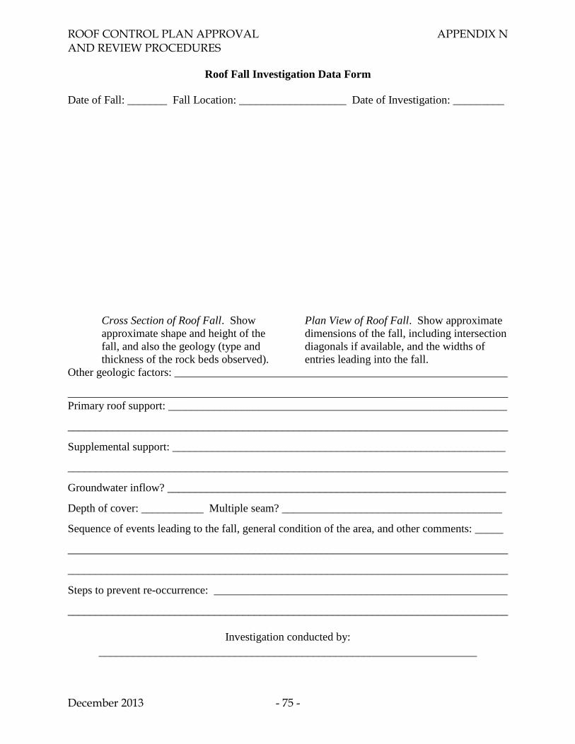
ROOF CONTROL PLAN APPROVAL APPENDIX N AND REVIEW PROCEDURES
December 2013 - 75 -
Roof Fall Investigation Data Form
Date of Fall: _______ Fall Location: ___________________ Date of Investigation: _________
Cross Section of Roof Fall. Show
approximate shape and height of the
fall, and also the geology (type and
thickness of the rock beds observed).
Plan View of Roof Fall. Show approximate
dimensions of the fall, including intersection
diagonals if available, and the widths of
entries leading into the fall.
Other geologic factors: ___________________________________________________________
______________________________________________________________________________
Primary roof support: ____________________________________________________________
______________________________________________________________________________
Supplemental support: ___________________________________________________________
______________________________________________________________________________
Groundwater inflow? ____________________________________________________________
Depth of cover: ___________ Multiple seam? _______________________________________
Sequence of events leading to the fall, general condition of the area, and other comments: _____
______________________________________________________________________________
______________________________________________________________________________
Steps to prevent re-occurrence: ____________________________________________________
______________________________________________________________________________
Investigation conducted by:
___________________________________________________________________
ROOF CONTROL PLAN APPROVAL APPENDIX O AND REVIEW PROCEDURES
December 2013 - 76 -
APPENDIX O
PROTECTING MINERS FROM HAZARDS RELATED TO RIB FALLS
MSHA standards require that “[t]he roof, face, and ribs of areas where persons work or travel
shall be supported or otherwise controlled to protect persons from hazards related to falls of ribs”
(30 CFR 75.202 (a)). The roof control plan, which is developed by the mine operator and
approved by the District Manager, must be “suitable to the prevailing geological conditions and
the mining system to be used at the mine” (30 CFR 75.220 (a) (1)). The mine operator is
required to propose revisions to the roof control plan “[w]hen conditions indicate that the plan is
not suitable for controlling…the ribs….” (30 CFR 75.223 (a) (1)).
The two most significant geologic conditions that contribute to hazards related to falls of ribs are
the seam height and the depth of cover. Analysis of the fatal accident reports from the 23 rib fall
fatalities that occurred during 1995-2010 indicates that 22 (96%) occurred where the mining
height was at least 7 feet and 18 (78%) occurred where the depth of cover was at least 700 feet.
The reports indicate that rock partings (rock layers contained within the coal seam) or rock
brows (rock layers above the coal seam) were present in nearly every instance.
Other conditions that have contributed to rib fall fatalities include:
additional rib stress due to multiple seam interactions or retreat mining,
large slickensides in the coal,
unusually high places prepared for overcasts or belt drives, and
unstable pillar corners.
Another significant factor associated with almost every fatal rib fall during 1995-2010 is that no
rib support had been installed at the accident location.
Rib bolts provide the best protection against rib falls. Since most rib fall incidents occur on the
working section, rib bolts are most effective when they are installed in a consistent pattern while
the roof is being bolted. Where the ribs are highly stressed, the rib bolts can be more closely
spaced and supplemented by additional surface coverage such as straps or mesh. Control of
taller ribs (e.g., 9 feet or higher) may be best achieved if two or more rows of rib bolts are
installed. Rib bolts should always be long enough to anchor securely beyond the disturbed
portion of the rib.
Outside-control, non-walk-through roof bolting machines place the machine operators between
the machine and the rib where they may be exposed to rib hazards. Every one of the roof bolt
operators killed by rib falls during 1995-2010 was operating an outside-control machine. Inside-
control, walk-through roof bolting machines significantly reduce the worker's exposure to
hazardous ribs. These machines also are commonly configured to provide horizontal rib bolt
hole drilling capability. Operators of mines where conditions create rib fall hazards are strongly
encouraged to use inside-control, walk-through roof bolting machines with horizontal rib bolting
capability.
ROOF CONTROL PLAN APPROVAL APPENDIX O AND REVIEW PROCEDURES
December 2013 - 77 -
Where rib bolting is not feasible, the rib fall hazard can be mitigated by other techniques
including roof channels fabricated with angled extensions that buttress the pillar rib, straps or
cables for wrapping the pillar rib, or standing supports. When standing supports are used for rib
control, it is essential that they be secured in such a manner that a hazard is not created should a
support be dislodged.
Mine safety programs and procedures should include methods for preventing, detecting,
reporting, and correcting hazardous conditions related to falls of the roof, face, and ribs. These
conditions can be detected during applicable preshift, supplemental, or on-shift examinations
(refer to Sections 30 CFR 75.360, 75.361 and 75.362). Hazardous conditions found during such
examinations must be corrected immediately or remain posted with a conspicuous danger sign
until corrected, pursuant to 30 CFR 75.363 (a).