Coal mine roadway support system handbook · 2018-04-05 · HSE Health & Safety Executive Coal mine...
76
HSE Health & Safety Executive Coal mine roadway support system handbook Prepared by Rock Mechanics Technology Ltd for the Health and Safety Executive 2004 RESEARCH REPORT 229a
Transcript of Coal mine roadway support system handbook · 2018-04-05 · HSE Health & Safety Executive Coal mine...

HSE Health & Safety
Executive
Coal mine roadway support system handbook
Prepared by Rock Mechanics Technology Ltdfor the Health and Safety Executive 2004
RESEARCH REPORT 229a

HSE Health & Safety
Executive
Coal mine roadway support system handbook
David Bigby BSc (Hons), PhD, MIMMM, CEng Rock Mechanics Technology Ltd
Bretby Business Park Ashby Road
Burton-on-Trent Staffordshire
DE15 0QD
This Handbook contains details of coal mine roadway support systems used in the UK, Germany and France plus some from South Africa, Canada and Australia which have been tested by the authors for their potential application in Europe.
The purpose of this Handbook is to provide a useful reference for European Mining Engineers who wish to obtain unbiased comparative information on the more innovative support systems that have become available in Europe in recent years. As such it does not include details of arch type supports and tends to concentrate on rock reinforcement systems and their related accessories. Where possible the Handbook provides information on the history of application, results of testing and appropriate applications for the various support systems. Also, in most cases it includes photographs of the systems, to help in identification and understanding their construction, and information on how the system’s performance can be properly monitored underground.
This Handbook was compiled by Rock Mechanics Technology Ltd (UK) as part of an HSE funded research Project entitled, “Safe Application of Mine Roadway Support Systems”. This was a three year Project which was completed in December 2002. This Project was part of a larger European Coal and Steel Community funded RTD Project No. 7220-PR 058, entitled “Improved Support Systems for Highly Stressed Roadways”. The larger Project included other partners from the UK, Germany and France who also contributed to the contents of this Handbook. These partners were as follows:
• UK Coal Limited (UK)
• Deutsche Steinkohle AG (Germany)
• Deutsche Montan Technologie GmbH (Germany)
• Houilleres Des Bassins du Centre at du Midi (France)
This report and the work it describes were funded by the Health and Safety Executive (HSE). Its contents, including any opinions and/or conclusions expressed, are those of the authors alone and do not necessarily reflect HSE policy.
HSE BOOKS

© Crown copyright 2004
First published 2004
ISBN 0 7176 2899 X
All rights reserved. No part of this publication may bereproduced, stored in a retrieval system, or transmitted inany form or by any means (electronic, mechanical,photocopying, recording or otherwise) without the priorwritten permission of the copyright owner.
Applications for reproduction should be made in writing to:Licensing Division, Her Majesty's Stationery Office, St Clements House, 2-16 Colegate, Norwich NR3 1BQ or by e-mail to [email protected]
ii

FOREWORD
This Handbook was compiled by Rock Mechanics Technology Ltd (UK) as part of an HSE funded research Project entitled, “Safe Application of Mine Roadway Support Systems”. This was a three year Project which was completed in December 2002. This Project was part of a larger European Coal and Steel Community funded RTD Project No. 7220-PR 058, entitled “Improved Support Systems for Highly Stressed Roadways”. The larger Project included other partners from the UK, Germany and France who also contributed to the contents of this Handbook. These partners were as follows:
x� UK Coal Limited (UK) x� Deutsche Steinkohle AG (Germany) x� Deutsche Montan Technologie GmbH (Germany) x� Houilleres Des Bassins du Centre at du Midi (France)
This Handbook therefore contains details of coal mine roadway support systems used in the UK, Germany and France plus some from South Africa, Canada and Australia which have been tested by the authors for their potential application in Europe.
The purpose of this Handbook is to provide a useful reference for European Mining Engineers who wish to obtain unbiased comparative information on the more innovative support systems that have become available in Europe in recent years. As such it does not include details of arch type supports and tends to concentrate on rock reinforcement systems and their related accessories. Where possible the Handbook provides information on the history of application, results of testing and appropriate applications for the various support systems. Also, in most cases it includes photographs of the systems, to help in identification and understanding their construction, and information on how the system’s performance can be properly monitored underground.
One problem encountered in compiling the Handbook has been that the three European countries involved have different regulations, national standards, acceptance criteria, codes of practice and testing methods for coal mine support systems. Therefore it has not been possible to provide directly comparable test data for each support system. For systems tested and used in the UK and France, the relevant testing methods, regulations and standards etc. have been directly summarised and referred to in the main body of the text. In the case of systems used in Germany, the regulations and testing regimes are described in a set of Appendices to the main text.
We should like to thank the many support system manufacturers for their co-operation and assistance in the preparation of this document. Whilst the authors have made every effort to ensure that the contents of this Handbook are factually correct, we cannot make any guarantee as to the correctness of the information contained herein and cannot accept any liability for the outcome of any decisions based upon the contents of this Handbook.
iii

iv

LIST OF CONTENTS
Page Number
Cover page iTitle page iiAbstract iiForeword iii List of Contents v
Reinforcement Tendon System 1 Rockbolt Systems 1
AT rockbolt system (UK) 1Continuously threaded 22mm high strength steel rockbolt (UK) 4ANCRALL rockbolt, A70-2 class (France) 6Low profile ribbing rockbolt, Fe E40 class (France) 8GW 25 rockbolt (Germany) 10Ribbed rockbolt, type KR (Germany) 11Self boring hollow rockbolts and injection anchors (Germany) 12Flexible rockbolt system (UK, France) 13GRP rib bolts, BS 7861-1:1996 (UK) 16K30-85 fibreglass rockbolt (France) 18GRP rockbolts (Germany) 20
Cablebolt Systems (Untensioned) 22Birdcaged cablebolts (UK) 22Mechanically bulbed cablebolts (also “Slimline” cablebolts) 25(UK)Nutcage cablebolts (UK) 26Flexible cable bolts (Germany) 28Cable bolt (300kN) BWZ (Germany) 30Cable bolt (750kN) Eurometal (Germany) 31Strand bolts (Germany) 32
Cablebolt Systems (Pre-tensioned) 33
Australia)
Australia)
Fabricated tensionable cablebolt system - The Megabolt (UK, 33
Fabricated tensionable cablebolt system - Megastrand (UK, 35
Crest tensionable strand cablebolt system (RSA) 37
Resin and Grout Encapsulants for Use with Reinforcement Systems 39Polyester resin to BS7861-1:1996 for use with AT bolt system 39(UK)LOKSET HS 60 resin (France) 41Cablebolting grout to BS 7861-2:1997 (UK) 42Thixotropic cable bolting grout - HPRG (UK) 44Cable bolting grout in capsule form - CBG capsule grout (UK) 45
Lagging and Surface Coating Systems 46Fosroc Tekflex surface coating (Canada) 46W straps (UK) 47
v

Steel wire mesh panels (UK) 48Flathook lagging (Germany) 49Canopy roof lagging (Germany) 50Hook lagging (Germany) 51Rolled lagging (Germany) 52
Standing Support Systems 53Cribbibng/Packing Systems 53
Link-n-Lock cribs (UK, USA) 53Hercules mat (UK, USA) 55Hardwood chock wood (UK) 57Artificial pillars (Germany) 59
Props 61Propsetter (UK, USA) 61Pink AS (Germany) 62
Appendix 1. Support system testing procedures and standards in 64German coal mines
1. Testing and approval of rockbolts in German coal 65mining2. Testing of lagging systems in Germany 67
vi

Support System Category: Reinforcement Tendon Systems
Sub Category: Rockbolt Systems
Generic name: AT rockbolt system (UK)
p
Nut
9 to 14 itch
Conical seat Domed washer plate
AT Rockbolt
AT Bolt and resin capsule
Brief Description: 22mm diameter high strength steel rockbolt and polyester resin system to British Standard BS 7861-1:1996, used as sole or supplementary support in UK coal mines, and usually referred to as the ‘AT’ rockbolt system.
Manufacturers: Rockbolts-Exchem (UK); Arnall Poland. Resin-Exchem(UK); Fosroc Mining (UK)
Application areas: Reinforcement of roof and sides in roadways driven in the solid. In the UK no rockbolt system is considered suitable for use as sole support in roadways driven close to existing goafs, in cross measures drivages or in advancing longwall gateroads. Typically used for sole support in roof and sides of gate roadways for retreat longwalls. If these are maintained behind the face then sufficient additional standing support is required. Also used as part of mixed support systems with steel arches etc.
General description: The 22mm diameter AT rockbolt with low profile LH thread ribbing is currently the only steel rockbolt used for sole support of roof in UK coal mine roadways.
It is defined in BS 7861-1:1996. The steel is homogeneous with minimum yield strength of 640MPa, and minimum tensile strength of 768MPa and a minimum strain prior to necking of 8%.The rib profile derives from an Australian design and is usually installed in holes drilled with a 27mm diameter rotary rock bit and fully encapsulated in polyester resin.
For UK sole support applications AT bolts are used with high strength polyester resin capsules also meeting the requirements of BS 7861-1:1996 (see separate entry).
AT bolts have an M24 thread at one end and are supplied with a “torque nut” and conical seat already fitted. The torque nut is designed to ensure that it does not rotate relative to the bolt during bolt installation through the resin to the back of the hole, but can be tightened by the drilling machine once the resin has set to a sufficient strength.
1

They can be installed using clockwise rotary hand held and machine mounted pneumatic and hydraulic rockbolting drills. Drills require relatively high thrust to spin the bolt into the hole through resin capsules due to the small annulus between bolt and hole, which is designed to achieve high bond strength and stiffness.
Application history: The AT bolt and resin system was originally developed to British Coal specifications in the late 1980’s, and has been used in the UK since 1990 for sole support of rockbolted roadways (rectangular section). Rockbolts to the same specification have also been produced in Poland since 1997.
Testing results: The UK Deep Mined Coal Industry Advisory Committee (DMCIAC) document entitled, “Guidance on the use of rockbolts to support roadways” (HSE books, 1996) defines underground bond strength requirements for steel rockbolts, measured using a short encapsulation pull test. This requires that, “in general, the average bond strength over 50% of the hole length needs to exceed 130kN for a bond length of 300mm.”
BS7861-1:1996 defines the laboratory axial Double Embedment test as a system type-test for AT bolts and resin. In this 250mm embedment length test the bond stiffness measured between 50 and 150kN must exceed 70kN/mm and the yield bond strength must exceed 200kN. Typical values for bond stiffness and yield bond strength for AT bolts and resin subjected to this test are 84kN/mm and 240kN respectively.
Another laboratory based system type-test used in the UK is the Laboratory Short Encapsulation Pull Test in which the system is pull tested in a hole drilled in a confined sandstone cylinder. For a 160mm embedment length, typical values for bond stiffness (30-70kN) and yield bond strength for AT bolts and resin are 270kN/mm and 147kN respectively.
BS 7861-1:1996 also specifies a system shear test, based on a shear frame used to load a test specimen installed in embedment tubes, with a minimum pass criterion of 250kN. AT bolts and resin subjected to this test have typical shear strength of around 270kN.
Support system design notes: The UK DMCIAC guidance document requires a minimum bolt density of 1 bolt per m2 and a minimum bolt length of 1.8m for roof support. The most common length of AT bolt used in the UK for roof reinforcement is 2.4m. Coupled AT bolts are not used as sole support. Shorter AT bolts are generally used in the ribs. AT bolts for roof and rib reinforcement are usually used in association with W straps and/or wire mesh. The document also describes a design verification procedure based on monitoring rockbolt loads using strain gauged rockbolts and roof movement using sonic extensometers.
The AT bolt is routinely included in roadway support designs using FLAC computer models. Typical load transfer properties employed are taken from the results of short encapsulation pull tests, preferably from the actual site. Monitoring data from strain gauged bolts and sonic extensometers is also used for model validation.
Safety procedures, based on roof movement monitoring using dual height telltales, are also described in the Guidance Document.
2

“Sentinel” AT bolts are available to provide an indication of whether rockbolts are broken in situ. These are based upon measuring electrical continuity. Ultrasonics have also been used successfully to determine in-situ AT bolt integrity. Galvanised AT rockbolts are available for use in corrosion prone areas. Laboratory system tests have shown these to perform as well as standard AT rockbolts.
3

Generic name: Continuously threaded 22mm high strength steel rockbolt (UK)
Brief Description: A nominal 22mm diameter high strength steel rockbolt with a continuous right hand thread along its entire length used in UK coal mines.
Manufacturers: SAT Systems (UK) Ltd (KT Anchor), Exchem (UK) Ltd
Application areas: Reinforcement of roof and sides in solid roadways. In the United Kingdom regularly used for support of the sides of gate roadways for retreat longwall mining. Can be used in conjunctions with steel arches and for remedial repair work, and additional localized support known as “spot bolting”. Recently adopted by UK Coal Ltd for sole support of the roof in UK gateroads with AT resin.
General Description: The continuous threaded rockbolt has been used in UK coal mines for reinforcement of mine sides in rockbolt supported gateroads since 1998, Typical lengths would be as follows for rib support; 1.2, 1.5 and 1.8 metres long. The bolts have recently been successfully trialled for sole support of the roof. Typical roof support lengths are 1.8, 2.1 and 2.4 metres. Longer versions typically 4-5 metres long have been used for long tendon support, particularly in ribs, and for fore poling in gate advances. Variations of the continuously thread bar supplied by SAH Ankertechnick (Germany) are used exclusively in the German Coal Mines, for bolting used in conjunction with resin or cementations grout capsules.
Due to its continuous thread the bar can be endlessly coupled on site if required.
The product conforms to the homogeneous steel requirement of BS7861-1: 1996 with a minimum yield strength in excess of 650 N/mm2, and a tensile strength of 800 N/mm2. The tensile strength at the end of the bolt using a 46mm nut exceeds 30 Tonnes.
The bar and in its nominal 22mm form is installed in holes drilled with a 27mm diameter rotary rock bit and typically encapsulated in polyester resin cartridges conforming to BS7861-1: 1996.
In the UK they are supplied with a 36mm AF Nut together with a conical seat and anti friction washer. Nuts can be supplied with a torque nut break out facility for use with either hand held bolting machines, stopers, or hydraulic bolter machines by using a higher strength torque break out pin.
Testing results: The product has been fully tested by the UK Testing House Rock Mechanics Technology Ltd, based at Bretby, Burton-on-Trent, Staffordshire, by
4

Graham Daws Associates, Ridings, Derbyshire and by the School of Chemical, Environmental and Mining Engineering, at the University of Nottingham.
These test procedures and definitions are contained within BS7861 and the system conforms and in some instances exceed these testing parameters.
The system does not comply with the current version of BS7861 in terms of the rib profile and nut.
5

Generic name: ANCRALL rockbolt, A70-2 class (France)
Brief description: 22 mm diameter steel coupled rockbolt
Manufacturers: Cocentall (FRANCE), (Ancrall department)
Application areas: Reinforcement of roof in solid roadways when resin bond flexibolts cannot be used due to the level of roof fracturing. In France not deemed suitable for use as sole support in roadways driven close to existing goafs or prone to seismic solicitations. In these cases, sufficient additional long cable bolts or/and standing support is required. Also used as part of mixed support systems with steel arches etc.
General description: The ANCRALL coupled rockbolt has been used for support of roof in French coal mine roadways in FRANCE since 1989 (rectangular section at depth superior to 1 000 m).
The steel is homogeneous with a minimum yield strength of 425 MPa, a minimum tensile strength of 710 to 810 MPa, a minimum resilience at 20° C of 30 J and a minimum strain prior to necking of 15 %.
The bolt has an elastic yield of 200 kN and an ultimate failure at 290 kN; in fact, to avoid projection of the bolt in the roadway at failure, it is used with a washer plate designed to fail at 250 kN.
This rockbolt is usually installed in holes drilled with a 43,5 mm diameter rotary rock bit (anchoring shells are available in different shapes designed in function of the roof hardness; in Provence colliery, it is typically used with an ANCRALL head type M24).
They can be installed using clockwise rotary hand held and machine mounted pneumatic and hydraulic rockbolting drills.
Testing results: There is no standard that defines laboratory or in situ tests in French norms. The mine manager defines his own test protocols in function of exploited grounds.
6

Support system design notes: The ANCRALL coupled bolt is routinely included in roadway support designs using UDEC & 3DEC. Typical load transfer properties employed are the same than those provided by the manufacturer. These can be modified according to the results of short encapsulation pull tests at the actual site.
The French guidance document requires a minimum bolt density of 0,5 bolt per m2
(for good quality roofs such as Provence one) and a minimum bolt length of 4 m. ANCRALL coupled bolts for roof are always used in association with wire mesh.
7

Generic name: Low profile ribbing rockbolt, Fe E40 class (France)
Brief description: 20 mm steel rockbolt with low profile ribbing designed for resin or mortar anchoring
Manufacturers: Cocentall, Lenoir et Mernier (France)
Application areas: They are used as first support just behind the front of the roadway drivage and in reinforcement of roof in solid roadways. In France not deemed suitable for use as sole support in roadways driven close to existing goafs or at depths superior to 1000 m. If these cases, sufficient additional standing support and/or long cablebolts are required. Also used as part of mixed support systems with steel arches etc.
General description: These two kinds of steel rockbolts are used for support of roof in French coal mine roadways since 1980 (rectangular section).
They are defined by NF M 81-450:1989. Their characteristics depend on the exploited ground. For Provence hard rocks, the 20 mm diameters bolts have a minimum elastic yield of 130 kN, a minimum ultimate tensile load of 216 kN (the minimum rupture nut load is of 200 kN, the minimum threaded end rupture load is of 200 kN, the minimum yield force of the threaded end is of 125 kN and the minimum elongation at the rupture must be 15 %.
The characteristics of the nut are defined in NF E 25-400 and must be of grade 5.
These bolts are usually installed in holes drilled with a 28mm diameter (for hard rocks) rotary rock bit and fully encapsulated in polyester resin. In France, they are used with WILLICH LOKSET HS 60 cartridge resin capsules (see separate entry).
8
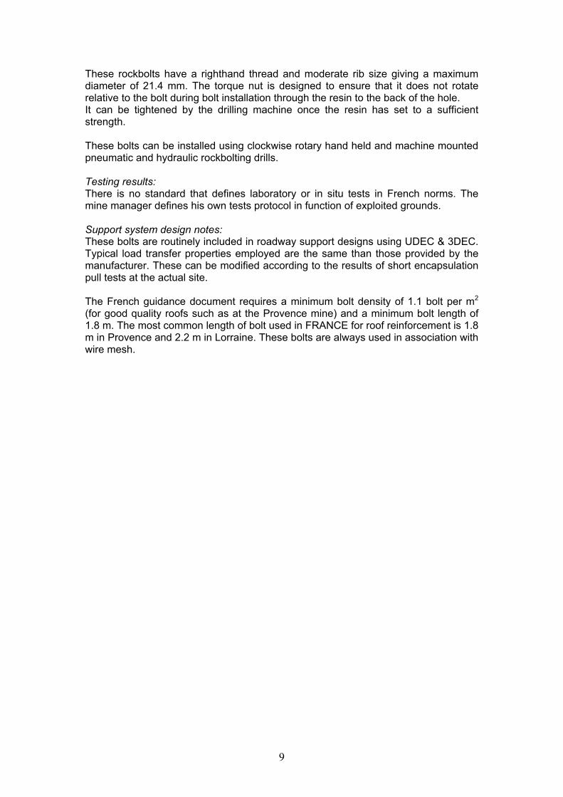
These rockbolts have a righthand thread and moderate rib size giving a maximum diameter of 21.4 mm. The torque nut is designed to ensure that it does not rotate relative to the bolt during bolt installation through the resin to the back of the hole. It can be tightened by the drilling machine once the resin has set to a sufficient strength.
These bolts can be installed using clockwise rotary hand held and machine mounted pneumatic and hydraulic rockbolting drills.
Testing results: There is no standard that defines laboratory or in situ tests in French norms. The mine manager defines his own tests protocol in function of exploited grounds.
Support system design notes: These bolts are routinely included in roadway support designs using UDEC & 3DEC. Typical load transfer properties employed are the same than those provided by the manufacturer. These can be modified according to the results of short encapsulation pull tests at the actual site.
The French guidance document requires a minimum bolt density of 1.1 bolt per m2
(for good quality roofs such as at the Provence mine) and a minimum bolt length of 1.8 m. The most common length of bolt used in FRANCE for roof reinforcement is 1.8 m in Provence and 2.2 m in Lorraine. These bolts are always used in association with wire mesh.
9

Generic name: GW 25 rockbolt (Germany)
Tens
ile lo
ad [k
N]
800
700
600
500
400
300
200
100
0 0 20 40 60 80 100 120 140 160 180 200
Displacement [mm]
Brief description: 25 mm diameter, steel rockbolt with standard thread ribbing (22 mm to 32 mm diameter production range, 25 mm common)
Manufacturers: SAH Ankertechnik GmbH Moers, GermanyBWZ Berg- und Industrietechnik GmbH Bottrop, Germany
Application areas: Reinforcement of roof and sides in roadways. In Germanyoften used for rockbolted roadways and as additional support element forsteel arched roadways.
General description:The GW 25 rockbolt is currently the standard rockbolt for German coal mine roadways.
The steel is homogenous with a minimum yield strength of 450 MPa, a minimum tensile strength of 700 MPa and a minimum strain prior failure (A5)of 20 %. The notch impact work amounts > 40 J according to minimumrequirements of approval.
The rib profile derives from GEWI design and is usually installed in holes of 32 mm and fully encapsulated in polyester resin. The method of filling the resin into the borehole is by cartridges with a diameter of 28 mm.
GW bolts have a GEWI 25 thread for the whole length. The bolt can be installed using hand held rotary machines or mounted pneumatic and hydraulic rockbolting drills.
Testing results: Maximum tensile load > 350 kN Elongation of installed maximum loaded rockbolt: > 55 mm Maximum shear load 90°/displacement: 420 kN/95 mm Maximum shear load 50°/displacement: 430 kN/35 mm
10

Generic name: Ribbed rockbolt, type KR (Germany)
Brief description: 22, 25, 31 mm diameter, steel rockbolt with ribbing
Manufacturers: BWZ Berg- und Industrietechnik GmbH Bottrop, Germany
Application areas: Reinforcement of roof and sides in solid roadways. In Germany also used for rockbolted roadways and as additional support element for steel arched roadways.
General description: The KR rockbolt is currently a standard rockbolt for additional rockbolting in German coal mine roadways supported with steel arches or for rockbolting support.
The steel is homogenous with a minimum yield strength of 450 MPa, a minimum tensile strength of 700 MPa and a minimum strain prior to necking of 20%. Notch impact work t 40 J.
The bolt is usually installed in holes of 32 mm and fully encapsulated in polyester resin. Quality standards requires bolts be used with polyester cartridge resin capsules (diameter 28 mm). In cases of secondary support pre-filled resin or mortar is used for encapsulation.
KR bolts have an metric thread of 100 or 150 mm length at one end of the bolt. The bolt can be installed using hand held rotary machines or mounted pneumatic and hydraulic rockbolting drills.
Testing results: The testing results of this bolt are quite similar to the GW bolt. The technical data for a bolt diameter of 25 mm are: Maximum tensile load 378 kN Elongation of installed maximum loaded rockbolt: 57 mm Maximum shear load 90°/displacement: 420 kN/ 95 mm Maximum shear load 50°/displacement: 437 kN/ 27 mm
11

Generic name: Self boring hollow rockbolts and injection anchors (Germany)
Wiborex type 30/11
Brief description: Self boring rockbolt with a hollow stem and profiled surface structure for injection and bolting.
Manufacturers: CarboTech/ Fosroc (sales and distribution for Wiborex bolt Germany), Ischebeck, Titan Injection Anchor (Germany)
Application areas: Reinforcement of roadways, stabilizing of strata above seam in the face T-junction area, rockbolting in weak and friable rock.
General description: Different sizes and types are available. German coal mines tend to use 30 mm diameter bolts with an internal hole diameter of 16 or 11 mm. For this bolt size a bit with a diameter of 33 mm is used for self drilling.
These systems allow drilling, injection and anchoring in one operation and can be used in many operations including longwall roof reinforcement and advancing support in mines. The Wiborex bolt stem is designed to be used in combination with Wilkit (silcate resin) but practical experience in coal mines using standard mortar or different injection materials has also shown adequate results. The individual mortar should be tested on site.
Testing results: Manufactors declaration (Wiborex system) Maximum tensile load: 320 kN (30/11 type) Yielding point: 260 kN Yield stress: 580 N/mm²
Support system design notes: These systems provide a solution for installation of rock bolts in weakened or friable ground where hole closure prior to bolt installation inhibit the standard rockbolting procedure using resin cartridges.
12

Generic name: Flexible rockbolt system (UK, France)
lexible bolt
embedment length)
20
0 2 4 6
Osborn “Reflex” f
Exchem “FSR” flexible bolt
Typical laboratory pull test results in confined sandstone (250mm
Bond Displacement (mm)
Load
Ton
nes
Flexible bolt / AT resin
Brief description: 23mm diameter high strength steel rope strand rockbolt and polyester resin system installed in 27mm drilled holes and used in conjunction with the AT rockbolt system, as sole support in UK coal mines. Also used as supplementary support with resin or grout encapsulation in UK and France.
Manufacturers: Osborn Strata Products, (UK); Exchem Ltd, (UK).
Application areas: Used in the UK as part of systematic support patterns in conjunction with the AT bolt system in conditions requiring reinforcement beyond the bolted height. In this application the flexible bolt is fully encapsulated with AT resin and installed with the rockbolts at the face of the heading. This application is covered by a DMCIAC guidance document entitled “Supplementary guidance on the use of flexible bolts in reinforcement for coal mines” (HSE Books, 2000).
Flexible bolts are sometimes used as supplementary support or remedial reinforcement with thixotropic grout, or a combination of resin and grout which allows pre-tensioning, (see separate entries for grouts used). In this application the flexible bolt is effectively a cable bolt. They are also used for rib reinforcement, in conjunction with resin or grout.
Remedial applications using only resin are not generally recommended due to the difficulty in achieving full encapsulation, and the risk of losing resin into existing fractures.
General description: Flexible bolts are currently available from two suppliers. The products use different strands, the Osborn product having 7 wires and the Exchem bolt 19, but have the same nominal diameter. They are steel rope strand cables of 23mm diameter and
13

approximately 55 tonnes tensile strength. The outer surface of the strand is profiled by rolling onto it a pattern of indents which results in a bond strength/stiffness similar to the AT rockbolt when used with AT resin in 27mm drilled holes. The development of a super slow version of the AT resin means that flexible bolts can be fully encapsulated in lengths up to 4m or more. A choice of end terminations including barrel and wedge, plain and threaded, is available.
Application history: Used as part of systematic support patterns in UK mines since 1996. The flexible bolt is arguably the most significant long tendon innovation in the UK since the introduction of the birdcaged cable. They are distinguished from plain cable systems previously used with resin capsules in Australia and elsewhere by high bond strength and full encapsulation. A DMCIAC guidance document covering this application was issued in 2000. Use with thixotropic grout as long remedial tendon roof reinforcement is a recent innovation, which allows full encapsulation of lengths up to 6m or more. Flexible bolts are currently being used in this way at two French coal mines.
Installation: Essentially the same as for the AT rockbolt. They can be installed using rotary hand held and machine mounted pneumatic and hydraulic rockbolting drills. Drills require relatively high thrust to spin the bolt into the hole through the resin capsule due to the small annulus between bolt and hole, which is designed to achieve high bond strength and stiffness. The maximum length which can be installed in this way depends on the drill used and the roadway height. Use of super slow resin allows 4m long bolts to be fully encapsulated in a 2.8m high roadway. The bolt, complete with end plate, is manually inserted into the hole and pushed up as far as possible before engaging the bolt in the drill spinning adaptor. The flexible bolt is then held to the roof whilst the resin cures.
Testing results: The ultimate tensile strength of both available types is approximately 550 kN, with yield strengths of around 450kN. The end fitting strengths for the Osborn Strata products version are equal to the cable strength, whilst for the Exchem product a minimum of 400kN is quoted. However end plates normally used will fail at considerably lower loads. The double embedment test used for AT rockbolts (BS 7861-1:1996) has also been used to assess flexible bolts and resin. Typical values for bond stiffness and yield bond strength for flexible bolts and resin are 120 kN/mm and 180 kN respectively.
Another laboratory based system type-test used in the UK is the Laboratory Short Encapsulation Pull Test in which the system is pull tested in a hole drilled in a confined sandstone cylinder. For a 250mm embedment length, typical values for bond stiffness (30-70kN) and yield bond strength for flexible bolts and AT resin are 270kN/mm and 210kN respectively.
Flexible bolts and AT resin have a shear strength of around 370kN when tested using the system shear test specified in BS 7861-1:1996 for AT bolts and resin.
Bond strength results using grout encapsulant vary depending on the grout and hole size used, but are typically significantly lower than for resin.
Support system design notes: UK design requirements for use as part of systematic support patterns in conjunction with the AT bolt system include system performance testing, minimum support pattern requirements and design verification monitoring and routine monitoring.
14

The UK DMCIAC document, “Supplementary Guidance on the use of flexible bolts in reinforcement systems for coal mines” (HSE Books,2000) defines underground bond strength requirements for steel flexible bolts used with rockbolts as sole support, measured using a short encapsulation pull test. This requires that, “the average bond strength should be no less than 130kN for a bond length of 300mm over 50% of the tested horizons.” At least one test undertaken above the rockbolted height also needs to exceed 130kN.
The guidance also stipulates minimum flexible bolt length as 1.8m and the minimum density of AT rockbolting used with flexible bolting as 1/m2, irrespective of the number of flexible bolts installed. Typically flexible bolts are 4m long and between 2 and 4 will be installed per metre of roadway advance where design studies, monitoring or previous experience indicate a requirement.
Design is commonly undertaken using FLAC computer modelling with bolt load transfer properties based on measured bond strengths.
Design verification monitoring is based on the use of sonic extensometers to confirm the position and magnitudes of significant roof strain. Strain gauged flexible bolts are available but have not been used to-date for design purposes.
Routine monitoring makes use of the triple height telltale as described in the guidance, with the top anchor a minimum of 5m above the roof horizon.
Experience of the use of flexible bolts in conjunction with thixotropic grout for remedial roof support is currently limited. It is recommended that coal mine applications at this stage should be subject to detailed monitoring and assessment to confirm support performance.
15

Generic name: GRP Rib bolts, BS 7861-1:1996 (UK)
GRP bolts
Rib side with GRP bolts
Brief description: Cuttable glass reinforced plastic rockbolts meeting BS 7861-1:1996 used as coal mine rib support.
Manufacturers: Weldgrip, (UK), Weidmann, (Switzerland).
Application areas: Used to support coal ribs in UK coal mines, especially using AT polyester resin encapsulant (see separate entry), and in conjunction with the AT rockbolt system. Also commonly used for supplementary reinforcement of coalfaces or immediate seam roof when face support problems occur.
Detailed description: GRP bar is cuttable, non-corrosive and has a high tensile strength. Two manufacturers currently supply GRP bolts meeting BS 7861-1:1996 to UK coal mines. Weldgrip supply the most common type in use in the UK, which is 22mm diameter, the Weidmann bolt used in the UK (K60-25) is 24mm diameter although both are normally installed in holes drilled using a 27mm bit. Both bolts have a surface profile to improve bond strength, that of the Weidmann bolt being of the continuously threaded type. End fittings comprise threaded ends with nut and dome washer or high load cup together with steel or plastic end plates. The use of torque nuts is optional. Where used, BS 7861-1:1996 defines torque nut settings. Can be supplied in any lengths up to 6m. Supplied with anti static coating for use in coal mines. BS 7861-1:1996 defines anti-static and fire resistance requirements.
Installation: Essentially the same as for the AT rockbolt. They can be installed using rotary pneumatic hand held or machine mounted pneumatic and hydraulic rockbolting drills. If using hand held drills to install rib bolts, medium or slow set AT resin is normally used, rather than a fast /slow combination to ease installation. Positive drive nut systems, rather than torque nuts, are often used in combination with handheld drills. Care should be taken during installation not to apply too high a torque to GRP as bolts as this can cause delamination.
Application history: GRP bolts have been used in the UK as coal rib support in conjunction with rockbolt support systems since 1987 and as face support and repair for a similar period. Main technical change since then has been the development of higher strength end
16

fittings. A specification for GRP rib bolts with a minimum diameter of 21.5mm was incorporated into BS 7861 in 1996. The 24mm diameter Weidmann bolt has been used in UK coal mines since 1998 in applications where it’s higher strength parameters are considered appropriate.
Testing results: BS 7861-1:1996 describes a range of tests on GRP bolts. The minimum tensile strength specified is 300kN and for the end fitting 60kN. Current systems have tensile strengths of around 400kN with end nut strength ranging from 75 to 200kN, depending on type. Non metallic plates are also supplied. These have a strength of around 70kN when tested to BS 7861-1:1996.
BS 7861-1:1996 defines the laboratory axial Double Embedment test as a system type-test for GRP bolts and resin. The bond strength must exceed 245kN for a bond length of 900mm. Values of bond strength for GRP bolts and resin subjected to this test range from 260kN (Weldgrip) up to the bolt tensile strength of 380 kN (Weidmann).
Another laboratory based system type-test used in the UK is the Laboratory Short Encapsulation Pull Test in which the system is pull tested in a hole drilled in a confined sandstone cylinder. For the Weldgrip bolt and Weidmann bolts with AT resin at 160mm embedment length, typical values for bond stiffness (25-50kN) are 102kN/mm and 72 kN/mm respectively and typical values for yield bond strength are 87kN. BS 7861-1:1996 also specifies a system shear test, based on a shear frame used to load a test specimen installed in embedment tubes, with a minimum pass criterion of 120 kN. GRP bolts and resin subjected to this test have typical shear strengths of 125kN (Weldgrip) and 145kN (Weidmann).
Support system design notes: GRP bolts are relatively weak in bending, and have a low elongation at fracture and consequently they are not used as sole roof support in European coal mines.
Typical UK coal mine gate road rib bolt patterns utilise 2 or 3 rib bolts per metre on the face side. Usual length is in the range 1.2 to 1.8m. Bond strength and end load capacity are lower than steel bolts and this should be taken into account in design.
Instrumentation and modelling approaches to design are possible. Rib extensometry can be used to confirm design and broken bolts can be detected using ultrasonics. Strain gauged GRP bolts are also available for design purposes.
Longer GRP rib bolts are sometimes used as remedial reinforcement for high deformation ribs, in conjunction with thixotropic grout in larger diameter holes. Hollow tube versions of GRP bars are also available. These can be used in conjunction with grout injection and can be coupled together if required. Corresponding strength parameters are lower than solid bar. Cablebolt and self drilling anchor versions of GRP bolts can also be obtained.
17

Generic name: K30-85 fibreglass rockbolt (France)
Brief description: 22 mm diameter fibreglass rockbolt for resin or cement anchoring
Manufacturer: Weidmann (Germany)
Application areas: Reinforcement of ribsides in solid roadways especially in face gates where the coal will be cut by plough or shearer.
General description: It is usually provided with a washer plate of diameter 200 mm; in Provence conditions, due to the high pressure of the coal on the wire mesh, it is used with a washer plate of 140 mm. This fibreglass bolt has a weight of 0.6 kg/m, its nut weights 50 g and its washer plate weights 210 g.
The fibreglass has a Young’s modulus of 44 GPa, a minimum tensile force of 310 kN.
The bolts have an ultimate tensile load of 310 kN and a minimum bolt head rupture force of 40 kN.
This rockbolt has a nut of 36 mm (SW). The threading is : WAG 27 mm / 150 mm Its extremity has a shape bevelled. The fibreglass bolt is usually installed in holes drilled with a 28 mm diameter rotary rock bit and fully encapsulated in polyester resin. It can be used with Willich LOKSET HS 60 cartridge resin capsules (see separate entry).
The Weidmann rockbolt has a righthand thread. The torque nut is designed to ensure that it does not rotate relative to the bolt during bolt installation through the resin to the back of the hole, but can be tightened by the drilling machine once the resin has set to a sufficient strength.
They can be installed using clockwise rotary hand held and machine mounted pneumatic and hydraulic rockbolting drills.
18

Testing results: There is no standard that define laboratory or in situ tests in French norms. The mine manager define his own tests protocol in function of exploited grounds.
Support system design notes: The Weidmann bolt is routinely included in roadway support designs using UDEC & 3DEC. Typical load transfer properties employed are the same than those provided by the manufacturer. These can be modified according to the results of short encapsulation pull tests at the actual site.
The French guidance document requires a minimum bolt density of 0.66 bolt per m2
and a minimum bolt length of 1.8 m. Weidmann bolts for rib reinforcement are always used in association with wire mesh.
19

Generic name: GRP rockbolts (Germany)
Brief description: Cuttable bolt, manufactured from glassfibre material and supplied in various diameters, surface structures and with rigid or hollow boltstems. The standard form in German coal mines is ribbed with the same profile as GW-steel bolts (left picture)
Manufacturers: Weidmann Plastics Technology Switzerland
Application areas: Reinforcement and temporary support. Often used for stabilising the seam before passage of the longwall face, for temporary support of the heading face and in the area of crosscuts during construction. The bolts’ tensile load capacity give benefits in fixing loosen blocks and the bolts can easily be recovered during the cutting process or blasting. In comparison to steel elements there are no problems in loading and haulage processing of the waste. The range of applications is limited by the deformation of the strata and convergence of the roadway. High amounts of convergence means that axial strata movement and high shear loads on the bolts can destroy the glassfibre material.
General description:These bolts have been used for many different applications in Germany. The standard bolt has a diameter of 25 mm, GW ribbing on the whole length of bolt stem and is used in a length of 2, 2.5 or 3 metres. The standard GW form allows the opportunity of rotary setting with pneumatic or hydraulic rigs.
Testing results: Maximum tensile load rigid bolt: > 378 kN Maximum tensile load hollow bolt: > 250 kN
20

Bolt nut maximum tensile load: 180 kN (steel nut 50 mm) / 100 kN plastic nut 72 mm) Minimum bonding length rigid bolt: < 600 mm (mortar Quickmix 1000-1) Elongation of installed maximum loaded rockbolt: 52 mm Maximum shear load 90°/displacement: 339 kN/119 mm Maximum shear load 50°/displacement: 395 kN/ 35 mm Elongation at breaking point, length 5 x diameter: > 3 % Weight: 0.9 kg/meter
Torsional moment rigid bolt stem >130Nm Torsional moment hollow bolt stem >100 Nm
Support system design notes: This type of bolt is very sensitive to shear load and torsion. So in most applications the bolt is used as an element of reinforcement and not as a support element. For calculations of the required support resistance the bolts are not taken into consideration for the standard Standsicherheitsnachweis. In numerical modeling it is possible to include the GRP bolt’s mechanical characteristics derived form testing results on installed rockbolts. For installation using drill rigs the maximum torsional moment of the bolts must be taken into consideration to avoid damage during setting process.
21

Sub Category: Cablebolt Systems (Untensioned)
Generic name: Birdcaged cablebolts (UK)
embedment pull test method
l i
in
600
400
Load
(kN
)
200
00 30
Single Birdcaged Cablebolt (centre) Axial reinforcement performance determined by the double
Sing e b rdcage and grout
Double birdcaged Cable and grout
Two Dyform strands and grout
Rockbolt and Res
Displacement (mm) 10 20
Single 7 wire Dyform strand (top)
Double Birdcaged Cablebolt (bottom)
Brief description: Steel rope strand cablebolts to BS 7861-2:1997, in which the wires are rewound to form a series of ‘birdcages’ to maximise system bond strength. Used in the UK with cementitious grout encapsulant as a long tendon roof support system. Normally supplied as double birdcaged cables, formed from two seven-wire strands and having nominal tensile strength of 60 tonnes and a nominal cage diameter of 47mm. These are usually installed in 55mm diameter holes in lengths of between 5 and 10m. Single birdcaged cables have a 30 tonne strength and a nominal cage diameter of 35mm and are installed in 43 mm holes.
Manufacturers: Osborn Strata Products, (UK), DSI, (UK).
Application areas: Used as part of systematic roof support patterns or as remedial roof support in conjunction with the AT bolt system in conditions requiring reinforcement beyond the bolted height, such as junctions and other large excavations, and in gateroads prior to face retreat. The cables are fully encapsulated with a suitable cementitious grout such as CBG grout (see separate entry). In the systematic support application they are installed within a specified distance of the face of an advancing roadway or before a specified distance in front of a retreating face line. Alternatively, in the remedial support application, they are installed in response to specified levels of roof movement, either on development or retreat.
Single birdcaged cables are also sometimes used for rib support and double birdcaged cables as supplementary support or remedial reinforcement in roadways supported by steel girders or arches.
General description: Birdcaged cablebolts currently used in UK coal mines, specified in BS 7861-2:1997, are manufactured from dyform strand conforming to BS 5896. This 15.2mm diameter 7 wire strand comprises 6 wires wound round a central king wire and has a nominal UTS of 30 tonnes. Single birdcaged cables are formed by rewinding a strand to form a series of birdcages of maximum diameter approximately 35mm. More commonly, double birdcaged cables are formed by combining two strands to give a cable of 60 tonnes nominal UTS and 47mm approximate maximum diameter. The frequency of
22
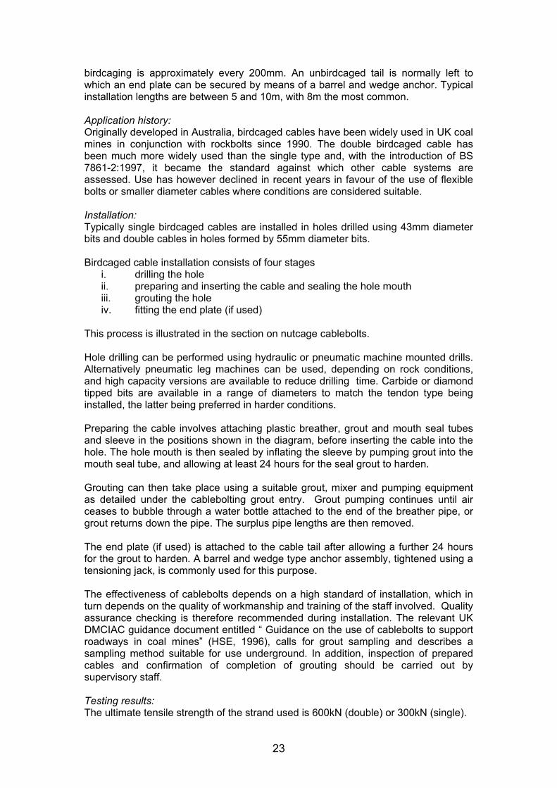
birdcaging is approximately every 200mm. An unbirdcaged tail is normally left to which an end plate can be secured by means of a barrel and wedge anchor. Typical installation lengths are between 5 and 10m, with 8m the most common.
Application history: Originally developed in Australia, birdcaged cables have been widely used in UK coal mines in conjunction with rockbolts since 1990. The double birdcaged cable has been much more widely used than the single type and, with the introduction of BS 7861-2:1997, it became the standard against which other cable systems are assessed. Use has however declined in recent years in favour of the use of flexible bolts or smaller diameter cables where conditions are considered suitable.
Installation: Typically single birdcaged cables are installed in holes drilled using 43mm diameter bits and double cables in holes formed by 55mm diameter bits.
Birdcaged cable installation consists of four stages i. drilling the hole ii. preparing and inserting the cable and sealing the hole mouth iii. grouting the hole iv. fitting the end plate (if used)
This process is illustrated in the section on nutcage cablebolts.
Hole drilling can be performed using hydraulic or pneumatic machine mounted drills. Alternatively pneumatic leg machines can be used, depending on rock conditions, and high capacity versions are available to reduce drilling time. Carbide or diamond tipped bits are available in a range of diameters to match the tendon type being installed, the latter being preferred in harder conditions.
Preparing the cable involves attaching plastic breather, grout and mouth seal tubes and sleeve in the positions shown in the diagram, before inserting the cable into the hole. The hole mouth is then sealed by inflating the sleeve by pumping grout into the mouth seal tube, and allowing at least 24 hours for the seal grout to harden.
Grouting can then take place using a suitable grout, mixer and pumping equipment as detailed under the cablebolting grout entry. Grout pumping continues until air ceases to bubble through a water bottle attached to the end of the breather pipe, or grout returns down the pipe. The surplus pipe lengths are then removed.
The end plate (if used) is attached to the cable tail after allowing a further 24 hours for the grout to harden. A barrel and wedge type anchor assembly, tightened using a tensioning jack, is commonly used for this purpose.
The effectiveness of cablebolts depends on a high standard of installation, which in turn depends on the quality of workmanship and training of the staff involved. Quality assurance checking is therefore recommended during installation. The relevant UK DMCIAC guidance document entitled “ Guidance on the use of cablebolts to support roadways in coal mines” (HSE, 1996), calls for grout sampling and describes a sampling method suitable for use underground. In addition, inspection of prepared cables and confirmation of completion of grouting should be carried out by supervisory staff.
Testing results: The ultimate tensile strength of the strand used is 600kN (double) or 300kN (single).
23

Axial and shear tests have been developed for the birdcaged cable, utilising cable sections installed in steel embedment tubes. These tests are described in BS 7861-2:1997. In the axial double embedment test with a bond length of 900mm, the bond stiffness measured between 200 and 400kN must exceed 100N/mm and the maximum load must exceed 560kN. For SBC the values are halved. The shear test specifies a minimum shear force of 350kN or 200KN respectively. Actual test results show both single and double birdcage cable bolts to comfortably exceed these System Performance requirements
Another laboratory based system type-test used in the UK is the Laboratory Short Encapsulation Pull Test in which the system is pull tested in a hole drilled in a confined sandstone cylinder. For double birdcaged cables in the sandstone used, a 600mm embedment length is sufficient to generate the full cable capacity.
Support system design notes: UK design recommendations are specified in a document issued by the Deep Mined Coal Industry Advisory Committee (DMCIAC), entitled “Guidance on the use of cablebolts to support roadways in coal mines” (HSE, 1996) and include system performance testing, minimum support pattern recommendations and design verification monitoring and routine monitoring.
Minimum length is specified as 8m in roadways less than 5m wide and 10m in other applications unless monitoring and geotechnical information indicates that shorter lengths are appropriate.
It should be noted that testing has shown that an increase in bulb spacing for bulbed cables will result in reduced bond strength and stiffness. Cables with increased bulb spacing may not comply with the system performance requirements of BS 7861-2:1997 and may require a corresponding increase in pattern density to achieve the same level of reinforcement.
Design verification monitoring is normally based on the use of sonic extensometers to confirm the position and magnitudes of significant roof strain.
Cablebolts can be simulated in FLAC computer models.
Routine monitoring makes use of the cablebolting dual height telltale as described in the DMCIAC guidance document with the top anchor a minimum of 1m above the top of the cable and the lower anchor 1m below the top of the cable. These are used in addition to rockbolting dual height telltales to give full information on position and magnitude of roof movement.
24

Generic name: Mechanically bulbed cablebolts (also “Slimline” cablebolts) (UK)
Double Minicage Cablebolt
Brief description: Seven wire die formed strand formed through mechanical axial compression into bulbed profile of approximately 25mm maximum diameter with approximately 160mm spacing of bulbs (6 bulbs per metre). Two strands are utilised to form a double bulbed cablebolt, which is intended to be installed in a 42-45mm drilled hole (see individual manufacturer’s data for exact product specifications).
Manufacturers: Osborn Strata Products (Minicage) (UK); MMTT Ltd (Garford Bulb) (UK).
Application areas: As for birdcaged cables. Single bulbed cables have occasionally been used as rib support, but roof support applications invariably utilise the double bulbed cable.
General description: Smaller diameter alternative to the birdcaged cable with cages of maximum nominal diameter 25mm. For roof support applications the double bulbed cable is usually installed in a 45mm hole. Other details are as for the double birdcage cable.
Application history: The double Minicage cable has been used in the UK since 1997 as an alternative to the double birdcage cable. The Garford Bulb cable has only recently been tested for UK application.
Installation: As for the birdcaged cable with the exception that the double bulbed cable can be installed in a 45mm diameter hole.
Testing results: The ultimate tensile strength of a double bulbed cable is greater than 600kN. Axial double embedment tests for the Minicage to BS 7861-2:1997 (but in 45mm diameter tubes), with a bond length of 900mm, give typical results as follows: maximum loads of 598-604kN with bond stiffness between 200 and 400kN varying from 105-153kN/mm. The shear test to BS 7861-2:1997 gives a typical maximum shear load of 367kN. These results comply with the System Performance requirements of BS 7861-2:1997 for double birdcaged cablebolts. Tests on the Garford bulb product (in 52mm embedment tubes) also show it to comply with the System Performance requirements of BS7861-2:1997 for double birdcaged cablebolts.
Support system design notes: In general as for the birdcaged cable. It should be noted that testing has shown that an increase in bulb spacing for bulbed cables will result in reduced bond strength and stiffness. Cables with increased bulb spacing may not comply with the system performance requirements of BS 7861-2:1997 and may require a corresponding increase in pattern density to achieve the same level of reinforcement.
25
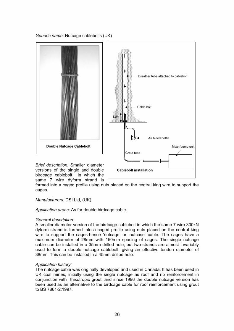
Generic name: Nutcage cablebolts (UK)
Mixer/pump unit
Grout tube
Air bleed bottle
Cable bolt
1.0m
Double Nutcage Cablebolt
Brief description: Smaller diameter
same 7 wire dyform strand is
Breather tube attached to cablebolt
Cablebolt installation versions of the single and double birdcage cablebolt in which the
formed into a caged profile using nuts placed on the central king wire to support the cages.
Manufacturers: DSI Ltd, (UK).
Application areas: As for double birdcage cable.
General description: A smaller diameter version of the birdcage cablebolt in which the same 7 wire 300kN dyform strand is formed into a caged profile using nuts placed on the central king wire to support the cages-hence ‘nutcage’ or ‘nutcase’ cable. The cages have a maximum diameter of 28mm with 150mm spacing of cages. The single nutcage cable can be installed in a 35mm drilled hole, but two strands are almost invariably used to form a double nutcage cablebolt, giving an effective tendon diameter of 38mm. This can be installed in a 45mm drilled hole.
Application history: The nutcage cable was originally developed and used in Canada. It has been used in UK coal mines, initially using the single nutcage as roof and rib reinforcement in conjunction with thixotropic grout, and since 1996 the double nutcage version has been used as an alternative to the birdcage cable for roof reinforcement using grout to BS 7861-2:1997.
26

Installation: As for the birdcaged cable with the exception that smaller diameter holes are required; 35mm (single), 45mm(double).
Testing results: The ultimate tensile strength of the strand used is 600kN (double) or 300kN (single). Axial double embedment tests to BS 7861-2:1997 (in 52mm internal diameter tubes), with a bond length of 900mm, give typical results for double cables with 150mm cage spacing as follows: maximum load 627kN with bond stiffness between 200 and 400kN of 101kN/mm. The shear test to BS 7861-2:1997 gives maximum loads exceeding 350kN. These results comply with the System Performance requirements of BS 7861-2:1997 for double birdcaged cablebolts.
Support system design notes: In general, as for the birdcage cable. It should be noted that testing has shown that an increase in bulb spacing for bulbed cables will result in reduced bond strength and stiffness. Cables with increased bulb spacing may not comply with the system performance requirements of BS 7861-2:1997 and may require a corresponding increase in pattern density to achieve the same level of reinforcement.
27

Generic name: Flexible cable bolts (Germany)
Example cable bolt: Eurometal Example strand bolt
Brief description: Flexible cable bolts of different types and with various diameters (see subsequent pages)
Manufacturers: BWZ, Gummert, SUSPA (Germany), Eurometal, (Poland)
Application areas: Reinforcement of roof in rectangular rockbolted roadways. Additional support of the face side and face entry in arched shaped roadways with steel arches or rockbolting support. In German coal mines these stranded cable bolts have been tested with good results for reinforcement in highly stressed rectangular roadways and they are often installed as additional support for the face entry in combination with props and shield supports.
General description: Flexible cable bolts used in Germany are constructed with various designs (see individual bolt types). They are classified according to a normative description of the cables and their components as follows:
Beam bolt/bundle bolt: Collection of bars (not drilled/twisted) Strand bolt: Bolt stem as a strand constructed with twisted wires Cable bolt: Bolt stem constructed with twisted strands Tensile bolt: Cable- or strand bolt constructed for pre-tension
The classification gives an explicit allocation for the type of construction. The special surface structure of birdcages or multiple birdcages, where used, gives an additional criterion of rockbolt type.
Many different construction types of flexible cable bolts used have been tested in Germany with various materials and numbers and diameters of wire/ strand. As a result the flexible cable bolts are also divided into classes of strength (tensile strength):
200 kN to 300 kN 300 kN to 400 kN 400 kN to 700 kN
Common designs are shown in the photographs above. In most applications the length of bolt used is between 4 metres and 8 metres. They are installed by pre-filling the borehole with mortar or by injection of mortar or resin after inserting the bolt into the borehole. Experience and quality assessment has shown the benefits of the injection method for bolts with a length of more than 4 metres.
In German coal mining, bird cage typed cable bolts are not common. This is due to the testing results for installed flexible, non bulbed cable bolts indicating that they are
28

sufficient for the requirements of planning and design of bolting patterns in current German applications. Tests on installed flexible cable bolts have shown that a grouted length of 600 mm can transfer a load of > 300 kN within a borehole of diameter 3 mm greater than the flexible cable bolt diameter. This is a similar result to standard rigid bolts e.g. GW-type or KR. Taking into consideration this fact, the German industry prefers to adopt systems which achieve the maximum bolt load with a minimum borehole diameter and does not choose to utilise the higher load transfer capabilities of bulbed cable bolts.
Testing results: The testing results are given for the different types in the following sheets.
Support system design notes: In numerical modelling the characteristic of tensile resistance as well as shear resistance and elongation of installed rockbolts are included from the testing results.
For flexible bolts it is important to take account of the minimum bonding length for transmitting the maximum bolt load for different kinds of resin or mortar used.
For the determination of required support density bolts are often considered as an instrument of suspension. Maximum predicted loads from unstable strata and fractured rock must be suspended by flexible bolts with a minimum factor of safety 1.5. It is also usual common to also take into account dynamic loading within the calculation.
29

Generic name: Cable bolt (300 kN) BWZ (Germany)
Zugprüfung: Prüfnummer: 2 (1130)
400
350
300
250
200
150
100
50
0 0 20 40 60 80 100 120 140 160 180 200
Zugweg [mm]
Brief description: Flexible bolts constructed with twisted strands containing wires
Manufacturers: BWZ, Bottrop, Germany Zu
gkra
ft [k
N]
Application areas: See German Flexible Cable Bolts above.
General description:Cable bolt with 4 strands, each containing 4 wires of 3mm diameter. Rockbolt headas aufgepresste Hülse with a metric thread M33. Rockbolt diameter 24 mm
In most applications the length of the bolt is between 4 metres and 8 metres. They are set by pre-filling the borehole with mortar or by injection of mortar or resin after inserting the bolt into the borehole. Experience and quality assessments show thebenefits of the injection method for bolts of more than 4 m length.
Testing results: Maximum tensile load: 338 kN. Elongation of installed maximum loaded rockbolt: 23 mm Minimum bonding length: 1200 mm (Quickmix 1000-1) Tensile load with angled bolthead (45 °): 234 kN Maximum shear load 90°/displacement: 332 kN/105 mm Maximum shear load 50°/displacement: 420 kN/28 mm
Support system design notes: See German Flexible Cable Bolts above.
Zug-Kraft
Max. Tragkraft: 372 [kN] Hersteller: BWZ Zugehöriger Zugweg: [mm] Typ: Seilanker (300 kN)
Mörtel: quickmix 1000-1 Prüfdatum: 21.08.00 Uhrzeit: 10:30 Vermörtelt: 18.08.00 Uhrzeit: 10:15 Bohrlochdurchmesser: 42 [mm] Gebirgerohr 1: Länge: 100 [mm]0 Gebirgerohr 2: Länge: 600 [mm] Eingebaute An l.: 1600 ker [mm] Versuchsaufbau:Minimale Verbundlänge
30

Generic name: Cable bolt (750 kN) Eurometal (Germany)
Brief description: Flexible bolts constructed with twisted strands containing wires
Manufacturers: Eurometal (Poland)
Application areas: See German Flexible Cable Bolts above.
General description: In most applications the length of the bolt is between 4 metres and 8 metres. They are set by pre-filling the borehole with a diameter of 50 mm with mortar or by injection of mortar or resin after inserting the bolt into the borehole. Experience and quality assessments show the benefits of the injection method for bolts of more than 4 m length.
Testing results: Maximum tensile load > 751 kN Minimum bonding length: < 1200 mm Elongation of installed maximum loaded rockbolt: > 32 mm
Support system design notes: See German Flexible Cable Bolts above.
31

Generic name: Strand bolts (Germany)
Example: Suspa strand bolt
(1053)
0 0
[mm]
]
i
i
l
Ei l
luft
] i ]
Zugprüfung: Prüfnummer: 1
100
200
300
400
500
600
20 40 60 80 100 120 140 160 180 200
Zugweg
Zugk
raft
[kN
Zug-Kraft
Hersteller: SUSPA Typ: L tzenanker Mörtel: quickmix 1000-1 Prüfdatum: 02.12.99 Uhrze t: 14:00 Vermörtelt: 25.11.99 Uhrzeit: 16:00 Bohr ochdurchmesser: 42 [mm] Gebirgerohr 1: Länge: 1200 [mm] Gebirgerohr 2: Länge: 1600 [mm]
ngebaute Anker .: 2800 [mm] Versuchsaufbau:
Bemerkungen: Versagen des Ankers durch Bruch in der K
Max. Tragkraft: 389 [kNZugehör ger Zugweg: 52 [mm
Brief description: Strand bolts with various numbers and diameters of strands
Manufacturers: SUSPA (Germany), ACRIL (Australia)
Application areas: See German Flexible Cable Bolts above.
General description: Strand bolt constructed with 7 twisted wires each of 6mm diameter. Installed in boreholes with a diameter of 42 mm. The bolt diameter is 18mm. The rockbolt head construction comprises a thread with a length of 120 mm.
Testing results: Maximum tensile load > 389 kN Minimum bonding length: < 1200 mm (mortar Quickmix 1000-1) Elongation of installed maximum loaded rockbolt: 52 mm Maximum shear load 90°/displacement: 339 kN/119 mm Maximum shear load 50°/displacement: 395 kN/ 35 mm
Support system design notes: See German Flexible Cable Bolts above.
In most tests of suitability this bolt gives quite similar results to the standard BWZ cable bolt (300 kN). The smooth surface structure gives a higher elongation in the tensile test. The higher elongation is not affected by the material characteristics.
32

Sub Category: Cablebolt Systems (Pre-tensioned)
Generic name: Fabricated tensionable cablebolt system – The Megabolt (UK, Australia)
– 2.4m resin/grout encapsulation
Displacement (mm)
0
200
400
600
0 10 20 30
630kN Megabolt
Laboratory pull test pretensioned Megabolt
Initial pre - tension
Load
(kN
)
Manufacturers: Megabolt (Australia). Available in Europe through Megabolt (UK).
Brief description: Fabricated high strength tensionable cablebolt intended for resin anchorage and post grouting. Used in Australia as alternative to the birdcaged cable.
Application areas: Used as an alternative to the birdcaged cable system as part of systematic roof support patterns or as remedial roof support in conjunction with rockbolts. Megabolts are anchored in polyester resin and pre-tensioned to provide immediate support. Subsequent encapsulation with a suitable cementitious grout provides long term support.
General description: Megabolts consist of multiple 70kN high tensile detented steel wires configured in continuous birdcaged lengths with a nominal birdcage spacing of 300mm. Each wire has a forged button head which engages within the threaded bolt head. A grout injection/breather tube runs internally through the length of the bolt to a position just below the length intended for resin anchorage. The head also incorporates a separate grout port and terminates in a hexagonal drive end for installation. A range of diameters and lengths are supplied. A 9 wire 40mm maximum diameter version, for example has a 630kN capacity and is installed in a 45-55mm diameter hole.
33
Installation: After drilling the appropriate diameter hole, using a rock or cablebolting drill, polyester resin capsules are inserted and the bolt pushed into the hole and mounted in the drill chuck using a suitable drive adaptor. The bolt is then spun through the resin and following completion of resin mixing to the supplier’s specification, it is held in place as the resin cures. The bolt can then be tensioned using a quick-acting hollow centre tensioning jack to the desired load (typically 25 tonnes). Post-grouting is normally achieved by grout injection via the grout port, with return via the centre breather pipe confirming full encapsulation.
Application history: Developed in Australia and used in coal mines there since 1997. Now in common use as a substitute for the birdcage cable. Application in the UK to date has been at three mines.
Testing results: Axial double embedment tests in CBG grout to BS 7861-2:1997 (but in 40mm internal diameter tubes), using the 9 wire version with a bond length of 900mm gave a stiffness of 190kN/mm at loads between 150 and 200kN. System stiffness between200 and 400kN was only 30kN/mm untensioned but 182kN/mm when tensioned andgrouted. A maximum load of 617kN was achieved. The shear test to BS 7861-2:1997 gave a maximum load of 420kN.
Another laboratory based system type-test used in the UK is the Laboratory ShortEncapsulation Pull Test in which the system is pull tested in a hole drilled in a confined sandstone cylinder. With 500mm embedment length in a 43mm diameterhole, this test gave peak loads of 428kN in grout and 239kN in resin. Yield bondstrengths at 20kN/mm stiffness were 244kN and 184kN respectively. The strength ofthe end assembly, including plate was 534kN. Tests undertaken with a pre-tensionedMegabolt demonstrated the high effective stiffness obtained below the pretension load.
Support system design notes:Although Megabolts do not comply with the definition of a birdcaged cable used in BS7861-2:1997, this standard and the UK DMCIAC guidance document (HSE, 1996) provide a suitable framework for system performance assessment for application incoal mines. The 9 wire version has a capacity similar to a double birdcaged cable,but the stiffness is lower if not pre-tensioned. The extent to which pre-tensioningenhances tendon performance in practice is uncertain and merits further research.
It should be noted that testing has shown that an increase in bulb spacing for bulbed cables will result in reduced bond strength and stiffness. Cables with increased bulb spacing may require a corresponding increase in pattern density to achieve the same level of reinforcement.
Design verification monitoring is normally based on the use of sonic extensometers to confirm the position and magnitudes of significant roof strain.
Routine monitoring makes use of the cablebolting dual height telltale as described inthe DMCIAC guidance document, with the top anchor a minimum of 1m above thetop of the cable and the lower anchor 1m below the top of the cable. These are usedin addition to rockbolting dual height telltales to give full information on position andmagnitude of roof movement.
34

Load
(kN
)
Generic name: Fabricated tensionable cablebolt system – Megastrand (UK, Australia)
Brief description: 28mm diameter high strength fabricated tensionable cablebolt 600
500
400
300
200
100
/
/
/
Test Ref DETT/1201 BC3 – Sample C
Test Ref DETT/1201 BC2 – Sample B
Test Ref DETT/1201 BC1 – Sample A
0 2 4 6 8 10 12 14 16 18 20 22 24 26 28 30
Displacement (mm)
intended for resin anchorage and post grouting. Manufacturers: Megabolt (Australia). Available in the UK through Megabolt (UK).
Application areas: Intended for use as an alternative to conventional cables and flexible bolts as part of systematic roof support patterns or as remedial roof support in conjunction with rockbolts. Megastrands are designed to be anchored in polyester resin and pre-tensioned to provide immediate support. Subsequent encapsulation with a thixotropic cementitious grout provides long term support.
General description: Megastrands consist of multiple 70kN high tensile ribbed steel wires configured as a single strand. The 28mm diameter version comprises 8 wires, giving a capacity of 560 kN, and is installed in a 34mm drilled hole. Each wire has a forged button head which engages within the threaded bolt head. The head terminates in a 36mm hexagonal drive end for installation. A grout injection tube runs internally through the strand to a point 2m from the upper end, where the strand is bulbed to allow outflow of the grout. Thixotropic grout is injected through the grout tube after tensioning to a typical load of 250kN. A range of lengths are available.
Installation: After drilling the appropriate diameter hole (34mm drilled for the 8 wire version), using a rock or cablebolting drill, a 28 x 1200mm medium set polyester resin capsule is inserted with the special tool supplied and the Megastrand pushed into the hole and mounted in the drill chuck using a suitable drive adaptor. It is then spun through the resin and, following completion of resin mixing to the supplier’s specification, it is held in place as the resin cures. The strand can then be tensioned using a hollow centre quick-acting tensioning jack. A tension load of 250kN is typically used. Postgrouting is achieved “top-down” by pumping thixotropic grout up through the central grout tube from where it pushes down the annulus and emerges from the “show-hole” in the end-plate.
35

Application history: Developed in Australia as a smaller diameter version of the Megabolt and recently introduced into coal mines there, where it is usually installed on drivage as part of systematic rockbolt support patterns. An initial trial took place in a UK coal mine in 2002 and use quickly spread to other sites and mines. The Megastrand is currently in use at three UK mines.
Testing results: The ultimate tensile strength of the 8 wire strand is 560kN. Testing has been undertaken using both AT resin and CBG grout encapsulants. Axial double embedment tests to BS 7861-2:1997 (but in 35mm internal diameter tubes), with a bond length of 900mm in CBG grout, give typical results as follows: maximum load 559kN with bond stiffness between 200 and 400kN of 110kN/mm. Axial double embedment tests in 35mm internal diameter tubes, with a bond length of 250mm in AT resin, typically give a maximum load of 310kN with bond stiffness between 50 and 150kN of 121kN/mm.
Shear test results to BS 7861-1:1996 and BS 7861-2:1997 using resin and grout encapsulants were 408 and 447kN respectively.
Support system design notes: The test results for the Megastrand suggest that it could be used as an alternative to flexible bolts as part of systematic support on drivage, or birdcaged cables as remedial support installed later. Bond strength and stiffness measurements indicate comparable performance with these tendons, once grouting is completed, without considering any additional benefit of pre-tensioning. Depending upon the application, the appropriate UK DMCIAC guidance documents (HSE, 1996, 2000) provide a general framework for system design and application in coal mines. In view of limited European experience with this tendon it is recommended that initial applications should take the form of monitored field trials to validate performance.
In Australia and elsewhere, a number of similar products which are anchored in resin and pre-tensioned are also currently in use as part of systematic support patterns in conjunction with rockbolts. They may be post grouted in which case a larger diameter hole is required for part of the length.
The relative virtues of systems utilising partial resin encapsulation and pretensioning, with and without post grouting, compared with full encapsulation resin or grout systems are currently uncertain.
36

Generic name: Crest tensionable strand cablebolt system (RSA)
Barrel and Wedge Anchor
240
160
80
0 8 0
Displacement (mm)
Double Bulb (for resin mixing)
Resin anchor
ire strand
-
Performance comparison: Crest cablebolt and flexible bolt system based on laboratory short encapsulation pull tests
Load
(kN
)
16
Plain 7 w
cablebolt Dome Plate, (with holes for grouting tubes if post grouted)
Crest Unbulbed Crest Unbulbed strand in South African grout
plain strand in Fasloc
Crest Bulbed plain strand in Fasloc resin
UK Flexible bolt in AT resin
Brief description: Plain strand cablebolt system combining resin anchorage with pretensioning and post grouting. Used in South African coal mines.
Manufacturers: Crest (South Africa), Steeldale (South Africa) and other South African manufacturers
Application areas: An alternative form of cablebolt which could be used in systematic roof support patterns or as remedial roof support in conjunction with rockbolts. The resin anchorage and pre-tensioning facility provides a level of immediate support, but the system has low bond strength and stiffness even when post grouted, and is not considered to be comparable with high performance systems such as the birdcage cable and flexible bolt.
General description: The Crest cable anchor system is formed from 7 wire plain strand most commonly of 15.2mm diameter and ultimate strength of 26 tonnes, although other sizes are also used. This size of cable is installed in a 36-38mm diameter hole. The cables are installed by spinning through resin and typically have one or two bulbs within the length intended for resin anchorage. They are pre-tensioned during fitting of a plate retained by a barrel and wedge. Grouting of the free cable length is then normally undertaken utilising access holes in the plate. Alternatively grouting may be undertaken immediately prior to tensioning.
Installation: A typical procedure is as follows. After drilling a 36-38mm diameter hole, using a rock or cablebolting drill, slow set 32mm diameter polyester resin capsules are inserted to give around 1-2m of encapsulation and the bolt pushed into the hole and mounted in the drill chuck using a suitable drive adaptor. The bolt is then spun through the resin and, following completion of resin mixing to the suppliers specification, it is held in place as the resin cures. Breather and filler tubes are attached and the hole sealed using sponge or similar material. The plate is placed in position with the tubes through the appropriate holes and a barrel and wedge type fitting placed over the strand. Versions giving visual indication of correct tensioning load are available. The bolts can then be tensioned up to 16 tonnes using a hollow centre tensioning jack. Post-grouting is achieved by grout injection via the filler tube, until grout exits the breather pipe, confirming full encapsulation.
37

Application history: Widely used in South African coal mines for a number of years for additional reinforcement of high risk bolted roadway sections. Not used in European coal mines to date.
Testing results: The UTS of the 15.2mm strand is 25 tonnes. The bond strength of all elements making up the system (Crest product) has been measured using the Laboratory Short Encapsulation Pull Test in which the system is pull tested in a hole drilled in a confined sandstone cylinder. South African supplied resin and grout were used in the tests with a 250mm embedment length.. The non bulbed sections had very low bond strengths in both resin and grout (less than 10kN in each case). Use of notched rather than plain cable resulted in only minor improvement. Although it was possible to generate greater axial loads in the bulbed section of the anchor, the bond strength and stiffness were still very low compared with birdcaged cables.
Although the resin anchorage and pre-tensioning facility provides a level of immediate support, this system has low bond strength and stiffness even when post grouted. The poor performance results primarily from the large hole size in relation to the diameter of the cable and it is not considered a suitable alternative to high performance un-pretensioned systems such as the birdcaged cable and flexible bolt or others utilising pretension, such as the Megastrand.
38

Support System Category: Resin and Grout Encapsulants for Use With Reinforcement Tendon Systems
Generic name: Polyester resin to BS 7861-1:1996 for use with the AT bolt system (UK).
Rockbolt installation
Nut tightening
Bolt Installation
Capsule Insertion
Drilling
using pneumatic leg drill
Brief description: Rockbolting resin meeting BS 7861-1:1996 and used with AT bolts as a sole support system in UK coal mines.
Manufacturers: Exchem (UK) (AT resin), Fosroc Mining Ltd, (UK) (Lokset HS resin).
Application areas: High strength polyester resin capsules to BS 7861-1:1996 used as the encapsulant for the AT bolt system and the flexible bolt system in sole support applications and commonly in rib bolting with steel and GRP bolts.
General description: High strength polyester resin to BS 7861-1:1996. Supplied as 24mm diameter capsules in fast (20 seconds) and slow (3 minutes) setting versions and a range of capsule lengths for use with the AT bolt system. The setting times quoted are approximate and decrease with increasing temperature. The fast set resin capsule is used at the top of the hole to allow rapid installation and nut tightening. The slow set resin below hardens after installation to give full encapsulation and small amount of pre-tension. AT resin was developed by Exchem for British Coal and first applied in 1990 and remains the most widely used rockbolt resin in the UK. Medium set (1 minute) and super slow set (10 minute) versions are also available for use with rib bolts and flexible bolts respectively. Lokset HS was introduced by Fosroc Mining in 1990 and also meets the British Standard. Compared with AT resin it has not yet found widespread use in the UK.
Handling requirements: Health and Safety requirements for use of this resin include skin and eye protection. It should also be noted that polyester resin is flammable. Capsule shelf life exceeds 6 months in normal conditions but is reduced by elevated temperatures.
Testing results: System test results for bond strength and stiffness using this resin are described under AT, GRP and flexible bolt sections. BS 7861-1:1996 also sets requirements for resin compressive strength, elastic modulus and creep. The compressive strength of 50mm cubes of slow set resin for example should exceed 80MPa after 24 hours, and the elastic modulus should be greater than 11GPa. These tests are used to confirm quality control during resin production. Although no test is specified, these resins
39

have low viscosity which is important to allow bolt installation with the small bolt / hole clearances employed, particularly when using pneumatic leg drills with limited thrust available.
40

Generic name: LOKSET HS 60 resin (France)
Brief description: 2 components resin cartridges used in French coal mines
Manufacturers: WILLICH Fosroc Gmbh (Germany)
Application areas: Reinforcement of roof and sides in solid roadways.
General description: It comes in the shape of an impervious, supple, transparent tube clipped on both ends (diameter 24 mm, variable lengths in function of the annulus volume). The inside is divided into 2 longitudinal compartments of unequal volumes (98 %, 2 %) containing respectively the resin and the catalyst.
The cartridges are introduced into the drill hole, then mixed up by the rock bolt’s rotary thrust. Components proportions are such that polymerisation takes place at the required speed while ensuring a very high strength.
The advantages of full column resin rock bolting over point anchors are : Not affected by scaling / spalling ; No need for re-tensioning ; Prevents fracture initiation ; Strengthens the rock, increases its cohesion, limits rock-layers displacements, keeps the roof-slab rigid.
Characteristics The chemical stability ensures WILLICH cartridges 12 months of shelf life at 20°(The storage conditions are a dry and fresh area without direct sun). Possibility to choose a precise setting time according to users equipment (between 8 s and 250 s).
The uniaxial compressive strength vary between 90.5 MPa and 98.5 MPa in function of setting time. The Young’s modulus vary between 14.5 GPa and 16 GPa in function of setting time. The minimum rupture strain is 8 %.
This resin has a relative density of 1.9 g/cm3 and is insoluble. Colour : green Smell : aromatic Shape : pasty Ebullition point : 168° C Lightning point : 62° C (the French regulations recommend a minimum of 55 °C) Self-flammability : 575° C Steams stress : 0.6 kPa at 20° C
41

Generic Name: Cablebolting grout to BS 7861-2:1997 (UK)
Lokset CB strength properties
Brief description: Cablebolting grout used with birdcaged and other cable types in roof support systems in UK coal mines. Meets the requirements of BS 7861-2:1997.
Manufacturers: Pozament Limited, (UK) (CBG), Fosroc Mining Ltd, (UK) (Lokset CB).
Application areas: Cablebolting grout to BS 7861-2:1997 used in the UK as an encapsulant for coal mine long tendon systems such as the birdcaged cable. Other applications have included use with rockbolts in ribsides.
General description: A pumpable high strength non- shrink grout based on Portland cement with pulverised fuel ash and other additives. Meets the requirements of BS 7861-2. The recommended water/solids ratio is 0.31. Can be pumped up to 20m or more. Grout powder should be added steadily to the required volume of water and mixed thoroughly using a standard grout mixer or propeller stirrer. The best results are achieved by using high shear mixing techniques for at least two minutes in order to disperse the additives and produce a homogeneous mix. This should then be pumped and injected by means of a wide throat pump. Recommended injection time is within 20 minutes of mixing, and initial set is around 3 hours. Suitable combined mixing and pump units for cable bolting applications are commercially available e.g. from Osborn Strata Products or Weldgrip.
Handling requirements: Normal Health and Safety precautions appropriate to the handling of a cement product are required, including skin and eye protection. Supplied pre-blended in 25kg sacks, or in bulk. Storage in dry conditions is important.
Testing results: The minimum strength of 100mm cubes specified in BS 7861-2:1997 is:
Curing Period 24 hours 3 days 7 days 28 days
Strength MPa 30
50 60 80
The elastic modulus should also be greater than 15.5 GPa after 14 days. The minimum positive expansion on setting is 0.05%. Both CBG and Lokset CB exceed these requirements when prepared as specified.
42

Routine sampling of mixed cable bolting grout underground is called for in the DMCIAC guidance document (HSE 1996). This document describes a test procedure using plastic sample bottles, from which a cylindrical test specimen is subsequently prepared. Sample density and compressive strength should fall within the ranges specified by the manufacturer.
43

Generic name: Thixotropic cable bolting grout-HPRG (UK)
Brief description: Cable bolting grout with thixotropic properties, used to limit grout loss into fractures.
Manufacturers: Pozament Limited, (UK)
Application areas: Thixotropic variant of CBG grout (see above), used as a long tendon encapsulant. The thixotropic property limits grout loss in fractured ground, making it especially useful for ribside reinforcement. Also used with pretensionable combined resin/grout systems. The drilled hole can be filled with grout prior to inserting the tendon, avoiding the need for post grouting. Meets the system test requirements specified in BS 7861-2:1997 for use with double birdcage cables, but compared with CBG, needs additional mixing time during preparation. Does not meet 28 day UCS requirement of BS 7861-2:1997.
General description: A pumpable high strength non-shrink grout based on Portland cement with pulverised fuel ash and other additives including a thixotropic agent. The recommended water/solids ratio is 0.30. Can be pumped up to 20m or more. Grout powder should be added steadily to the required volume of water and mixed thoroughly using a standard grout mixer or propeller stirrer. The best results are achieved by using high shear mixing techniques for at least five minutes in order to disperse the additives and produce a homogeneous mix. This should then be pumped and injected by means of a wide throat pump. Working time is 20-30 minutes and initial set is around 4 hours. Suitable combined mixing and pump units for cable bolting applications are commercially available e.g. from Osborn Strata Products or Weldgrip.
Handling requirements: Normal Health and Safety precautions appropriate to the handling of a cement product are required, including skin and eye protection. Supplied pre-blended in 16 kg or 25kg sacks, or in bulk. Storage in dry conditions is important.
Testing results: The strength of 100mm cubes meets the requirements specified in BS 7861-2:1997 after 24 hours and 7 days, but later strength gain falls below the minimum specification.
Typical results: Curing Period Strength MPa 24 hours 41.4 7 days 65.0 28 days 72.0
Routine sampling of mixed cable bolting grout underground is called for in the DMCIAC guidance document (HSE 1996). This document describes a test procedure using plastic sample bottles, from which a cylindrical test specimen is subsequently be prepared. Sample density and compressive strength should fall within the ranges specified by the manufacturer.
44

Generic Name: Cable bolting grout in capsule form-CBG capsule grout (UK)
Brief description: Cable bolting grout with thixotropic properties in capsule form primarily intended for use with rib reinforcement tendons.
Manufacturers: Pozament Limited, (UK).
Application areas: A user friendly alternative to conventionally mixed grout for ribside tendon systems, supplementary support/repair applications and pre-tensionable combined systems. Preformed 3.75kg capsules are soaked in water and the grout placed using a simple capsule pump. The thixotropic properties limit grout loss into fractures, making it especially useful for ribside reinforcement. Also used with pre-tensionable combined resin/grout systems. The drilled hole can be filled with grout prior to inserting the tendon, avoiding the need for post grouting.
General description: A pumpable non-shrink grout based on Portland cement with pulverised fuel ash and other additives including a thixotropic agent. The recommended water/solids ratio is 0.28. Can be pumped up to 20m or more. The grout capsules are unwrapped from their plastic sleeves and submerged in clean water for a minimum of 7 minutes. The material is injected using a purpose designed pneumatic capsule pump. Injection should take place within 20 minutes and initial set is around 5 hours.
Handling requirements: Normal Health and Safety precautions appropriate to the handling of a cement product are required, including skin and eye protection. Supplied pre-blended in packs of three 3.75kg capsules.
Testing results: The strength of 100mm cubes meets the requirements specified in BS 7861-2:1997 after 24 hours, but later strength gain falls below the minimum specification.
Typical results: Curing Period Strength MPa 24 hours 43 7 days 55
28 days 72
Routine sampling of mixed cable bolting grout underground is called for in the DMCIAC guidance document (HSE 1996). This document describes a test procedure using plastic sample bottles, from which a cylindrical test specimen is subsequently prepared. Sample density and compressive strength should fall within the ranges specified by the manufacturer.
45

Support System Category: Lagging and Surface Coating Systems
Generic name: Fosroc Tekflex surface coating (Canada)
Brief Description: Flexible, flame retardant and water resistant sprayed cementitious coating with applications in mine support. Has potential applications in European coal mines subject to appropriate testing and evaluation.
Manufacturers: Fosroc Mining Ltd, (UK)
Application Areas: Consolidation, sealing , protection and support of mine ribs and similar surfaces in coal and other mines. Can potentially be used as a replacement for steel mesh and similar surface support systems.
General description: Adhesive cement based surface coating with fibre reinforcement. Flexible, flame retardant, and water resistant when set. Can be applied up to 4mm thick in one pass spray application. Application can be undertaken at temperatures between 4 and 40 degrees centigrade with setting taking around 2 hours, depending on temperature. Application equipment is available from the manufacturers.
Application history: Used as a replacement for wire mesh in a Canadian and a Portuguese hard rock mine since 1998 and is in use as rib and supplementary face support in US and Australian coal mines.
Handling requirements: Health and Safety precautions appropriate to the handling and application of a sprayed cement product are required, including skin and eye protection and precautions against dust and noise.
Testing results: Needs appropriate testing to investigate potential European coal mine applications.
Support system design notes: Completion of a documented appropriate testing and evaluation scheme is advised prior to use in the UK in a support application in order to comply with current UK mining support regulations.
46

Generic Name: W Straps (UK)
Brief Description: 1.8mm thick steel straps used across rockbolted roadway widths, either alone or in conjunction with steel mesh. Holes drilled along the strap width are used to locate the rockbolts across the roadway.
Manufacturer: Osborn Strata Products (UK)
General Description: The W strap name is derived from the section profile produced by roll forming. Manufactured from high tensile steel, with a smooth mill rolled edge, W straps are used in conjunction with rock bolts to provide additional support and confinement of the immediate roof. When rock bolts are installed through the W strap, support tension can occur between the bolts via the W strap helping provide a trussing effect between the bolts and along the strap length.
The material used is 1.8mm thick BC 242-carbon manganese steel. This special grade has a yield of 350 N/mm2 and an ultimate tensile strength provides a strap tensile load in excess of 210 kN and at the same time allows the W strap to follow the contours of the rock bolted roof.
The W strap through a series of punched holes provides a controlled template of the designed roof-bolting pattern. This pattern is tailor made to suit individual geological conditions as the roof bolthole centres can be simply adjusted during the manufacturing process. These boltholes are available in different sizes and shapes to suit installation requirements.
W straps can also be provided with service line slots, again at interval spacing to suit local requirements. These service line slots provide a most convenient suspension anchor point for cables; hoses, ventilation ducting and other lightweight services required in mine roadways.
47

Generic Name: Steel Wire Mesh Panels (UK)
Brief Description: Wire mesh panels used for lagging roofbolted roadways.
Manufacture: Weldgrip (UK).
General Description: Wire mesh panels are manufactured from 0 to10 gauge cold drawn wire to customer requirements. A typical wire mesh roofbolting panel used in a UK rectangular roadway is made from 8 gauge self coloured wire, 75 x 75mm apertures with the width and depth custom made to the particular roadway size and cyclic advance. A broad thin steel strap is welded to the panel, which has holes at regular intervals along its length. This gives additional strength to the wire mesh but more importantly provides a template for the positioning of the rockbolts in the roof. Roofbolting mesh panels are also cranked along one leading edge with hooks welded to the opposite side. This allows the panels to be hooked together during installation making it easier and safer to handle and provides a continuous mesh cover to the roof. Side panels for roofbolting can be either wire mesh or a geotextile. The steel mesh type typically has hooks to afford attachment to the roof panel during installation and is sufficiently wide enough to overlap adjacent installed panels. The geotextile type is generally attached to the steel roof panel during manufacturing and hangs down from the roof panel when installed. Both types of side panel are secured to the roadway sides by roofbolts.
Wire mesh panels for arch section roadways in the UK are normally made from a heaver section wire (e.g. 8mm welded on 5mm wire) but smaller section panels. Like the roofbolting mesh they have hooks to interlock with adjacent panels.
Application Areas: Wire mesh panels are used for containment of the immediate roof and sides in both square and arch section roadways. They form a continuous steel cover to the surface of the strata thus preventing spalling.
The dimensions of the roofbolting panels are tailored to the roadway section and cyclic advance of the mining system. They also provide an additional safety cover for the heading team at the front of rockbolted drivages while operations are taking place. This is achieved by hanging additional panels down from the last installed roof panel and using “sprags” to restrain the mesh against the face of the heading. Wire mesh panels in arched roadways are used either to cover the crown or the whole arch section dependent on roadway conditions. Wire mesh panels are also used in face salvage operations, to provide roof support of the immediate strata between the roofbolts, from the face side to the back of the powered supports.
48

Generic name: Flathook lagging (Germany)
Brief description: Segment lagging with separate connection elements. The segments are constructed as a welded grid with steel rods.
Manufacturers: Dr. Fenne, (Germany)
Application areas: For lagging of rockbolting and standing support in rectangular and arch shaped roadways. Lagging of shaft support, reconstruction of roadway support and for support on face entry.
General description: The lagging is constructed with separate segments with a width of 500 mm and a length according to support spacing (600 mm to 1000 mm). The segment incorporates wires with a diameter of 4,6 and 8 mm. The 8 mm diameter wire is orientated to the roadway heading direction. The connection between the segments is designed with hooks in the heading direction. The connection in the circumferential direction is achieved with additional wires.
Testing results: The material parameters achieve the minimum requirements mentioned in the Annex on Test Methods. The data sheet is given in RAG N 162301.
The installed lagging Maximum resistance: 305 kN Maximum deformation: 154 mm Work capacity of lagging 47,2 kJ
49

Generic name: Canopy roof lagging (Germany)
Manufacturers: Dr. R. Fenne KG (Germany)
Brief description: Segment lagging with separate connection elements
Application areas: For lagging in rockbolting and standing support in rectangular and arch shaped roadways. Lagging of shaft support, reconstruction of roadway support and for support on face entry.
General description: The lagging is constructed with separate segments with a size of 165 mm x 500 mm. The segment incorporates wires with a diameter of 4,6 and 7 mm. The 7 mm diameter wire is orientated to the roadway heading direction. The connection between the segments is designed with hooks (circumferential direction) and by connection rods (heading direction). The connection rod has a diameter of 7 mm and is fixed to the installing position with a hook.
Testing results: The installed lagging Maximum resistance: 280 kN Maximum deformation: 182 mm Work capacity of lagging 53,3 kJ
50
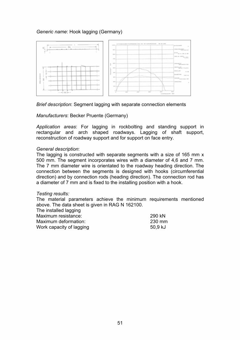
Generic name: Hook lagging (Germany)
Brief description: Segment lagging with separate connection elements
Manufacturers: Becker Pruente (Germany)
Application areas: For lagging in rockbolting and standing support in rectangular and arch shaped roadways. Lagging of shaft support, reconstruction of roadway support and for support on face entry.
General description: The lagging is constructed with separate segments with a size of 165 mm x 500 mm. The segment incorporates wires with a diameter of 4,6 and 7 mm. The 7 mm diameter wire is orientated to the roadway heading direction. The connection between the segments is designed with hooks (circumferential direction) and by connection rods (heading direction). The connection rod has a diameter of 7 mm and is fixed to the installing position with a hook.
Testing results: The material parameters achieve the minimum requirements mentioned above. The data sheet is given in RAG N 162100. The installed lagging Maximum resistance: 290 kN Maximum deformation: 230 mm Work capacity of lagging 50,9 kJ
51

Generic name: Rolled lagging (Germany)
Brief description: Rolled mesh lagging
Manufacturers: Rösler Draht (Germany)
Application areas: Standard lagging for rockbolted arch shaped roadways in German coal mines.
General description: The lagging is constructed as mesh that is rolled for transportation. In standard applications for arch shaped roadways 3 segments are used with a length of approximately 7 m each. The width is standardised to 1500 mm or 3000 mm. The spacing of wires in the roadway direction or circumferential direction depends upon the rockbolting pattern. Standardised pattern of 750 mm x 750 mm, 800 mm x 800 mm and 800 mm x 1000 mm are widely used. There is no connection between the segments except for the bolts so the segments are approximately 250 mm wider than the distance between the bolt rows to allow an overlap.
Testing results: (750 mm x 750 mm) Maximum resistance: 160 kN Maximum deformation: 260 mm Work capacity of lagging 20 kJ
52

Support System Category: Standing Support Systems
Sub Category: Cribbing/Packing Systems
Generic name: Link-n-Lock cribs (UK, USA)
Brief Description: Wooden rectangular prisms engineered with a simple interlocking mechanism. Individual lengths of various sizes built into layered vertical columns.
Manufacturers: Strata Products Ltd (UK)
Application Areas: Passive secondary or temporary support of mine roof and sides. Systematically set in advance of retreating longwalls to maintain a degree of stability, particularly in the front abutment zone. Used as a quickly installed temporary measure prior to the installation of additional active support. Their application is predominately as a final solution to difficult strata conditions. They are not ideal for use in transport or main access roadways.
General Description: Rectangular blocks are used to systematically build stacked columns with a simple interlocking mechanism built into each block increasing column stability. Each element is placed in turn, alternating 90o to the previous element, so a column is built vertically tight to the roof. Blocks are produced in various lengths from 500mm to 180mm (18” to 72”) and are available in 150mm and 200mm rise. The Link-n-Lock is more expensive per unit than conventional cribs, however the smaller lightweight components are easier to handle resulting in reduced operational costs.
Test Results: The 27” Link-n-Lock (4-point system) and standard 30” crib (9 point system) exhibit an equivalent deformation of 300mm at 150 tonnes (1335kN) load. The stiffer Link-n-Lock support loads more rapidly, supporting 100 tonnes of load at 50mm deformation as opposed to the 9-point cribs load of 80 tonnes at the same deformation.
A similar comparison of the 21” Oak Link-n-Lock against a standard 30” hardwood 4point crib has been made. The Link-n-Lock supports a load of 60 tonnes at 50mm
53
displacement and 100 tonnes at 250mm displacement whereas the standard crib supports 40 tonnes at 50mm displacement and 75 tonnes at 250mm displacement.
Support System Design Notes: The Link-n-Lock is a four-point crib system designed for use in mining heights up to 5.0 metres. Column stability is relative to column height. However interlocking allows for higher aspect ratios to be achieved than in conventional systems. A feature resulting from the interlocking is that 100% contact between layers is achieved. This means that the system is timber efficient, using 100% of the timber for roof support, thus allowing for up to 50% less timber to be employed to achieve the same strength as a conventional 4-point crib.
A further feature of the interlocking mechanism is that the overhang of elements is consistent, being designed to achieve optimum efficiency of the support. This is enhanced by the fact that each element is engineered using selected single species timber guaranteeing uniform size predictable performance. Link-n-Lock can be constructed rectangular or square depending upon operational requirements, giving the system greater flexibility.
54

Generic Name: Hercules mat (UK, USA)
Brief Description: System of prefabricated high capacity timber mats layered systematically to form vertical columns (cribs).
Manufacturers: Strata Products Ltd (UK)
Application Areas: Secondary or temporary support of mine roadway roof and sides. The Hercules system is designed for areas that require high support capacity. Their application is predominately as a final solution to difficult strata conditions, such as in “stress notched” tailgates or highly stressed zones. They have been successfully utilised in some cases to stabilize pre-driven recovery chutes against front abutment during the longwall rundown phase.
General Description: Individual mats are constructed by placing rectangular timber slabs in parallel to one another, separated by vertical grain blocks on the side. High tensile steel wire is then spun through the mat, binding the components together. To construct a crib, layers of mat are placed upon one another, each being rotated 90o
to create a crib effect. The vertical blocks form a fake column through the centre of the crib.
The Hercules Mats are produced in 4 size ranges, ranging from the 530mm long 4 point mat consisting of 2 slabs and 2 blocks per layer, to the larger 1400mm long 16 point mat consisting of 2 slabs and 8 blocks. The latter requires 2 units per layer, being designed this way for purposes of handling and transportation.
Test Results: When tested against standard cribs, Hercules Mats exhibited substantially increased yield strengths. The 4-point Poplar Mat loaded to 100 tonnes at 50mm deflection, as opposed to 70 tonnes for a standard 9-point crib and 40 tonnes for a standard 4-point crib at equivalent deformation.
The standard 9-point crib supported approximately 70 tonnes of loads at 50mm of deflection, as opposed to approximately 180 tonnes load at 50mm deflection for the 9-point Poplar Hercules Mat and 300 tonnes load at 50mm deflection for the Oak
55

Hercules Mat. The high capacity 16 point Oak Mat supports approximately 600 tonnes load for the equivalent 50mm deflection and 750 tonnes at 225mm deflection.
Support System Design Notes: Hercules Mats are an effective way to use timber to generate high capacity supports that provide high initial stiffness as well as a longterm yield. They utilise the strength properties of timber, benefiting from the fact that the parallel (vertical) grain of timber is stronger than the perpendicular grain.
Due to its design, the Hercules Mat would support approximately 550 to 600 tonnes as opposed to the 200 to 250 tonnes supported by the Link-n-Lock of equivalent size. A feature of the Mats is that designs can be altered to suit roadway conditions, with support capacity enhanced by using different timber species. The interlocking nature of individual layers ensures consistency of performance.
56

Generic Name: Hardwood chock wood (UK)
Brief Description: Hardwood shaped in a rectangular prism of various sizes built into a layered vertical columns (crib)
Manufacturers: Sharpe Brothers (UK).
Application Areas: Secondary and temporary support of mine roof and sides. Systematically set in advance of retreating longwalls in the UK to maintain a degree of excavation stability. Used in some circumstances as temporary measure prior to the installation of addition dynamic support. Their application is mainly used as a final solution to difficult support conditions. They offer limited resistance to lateral force.
General Description: Rectangular blocks made from hardwoods used to build stacked column (cribs) of either 2 on 2 (4 point) or 3 on 3 (nine point) depending on required size. The blocks are produced in varies sizes from 125 x 125 x 660 to 150 x 150 x 1200mm and can either be rough cut or smooth planed. All stacked columns are built by placing blocks in layers at alternate 90o angles. The chock-wood columns are then built vertically tight to the roof.
Testing Results: To date there is no British standard requirement for Hardwood cribs. However, testing of the common used woods and designs has been carried out (see diagrams).
Support System Design Notes: Wood cribs are constructed typically in 4 point or 9 point configurations. The capacity of the wood crib is determined primarily by the contact area. 9-point cribs are about 2.25 times as strong as 4 point. Two rows of 4point cribs can be placed with one row of 9-point cribs without any loss of support capacity.
Well-constructed wood cribs will yield through 20% strain (from the original crib height to 80% of the original crib height) before shedding load. Wood cribs should be constructed from the same type of wood. If different types of wood are used, they should have a similar strength and hardness. Mixed hardwood cribs will typically provide about 70% of the capacity of an all oak crib. Cribs constructed from hardwoods and softwoods will perform like softwood cribs.
Overhanging the timber during crib construction will greatly improve stability and increase the capacity of the crib by 10%. The overhang distance should be one half the timber width, i.e. a 75mm overhang for a 150mm timber width. The thickness of
57

the crib block should not exceed the width of the crib block. Cribs construction from rectangular crib blocks should be constructed with wide side down.
The aspect ratio of the crib should be between 2.5 and 5.0. Timber lengths should increase by 150mm for each additional 300mm of crib height, starting with 660mm timbers at a height of 1550mm.
58

Generic name: Artificial pillars (Germany)
Brief description: Mortar filled tubular bags for roadside packing (eg. Bullflex system)
Manufacturers: Gebhardt & Koenig - Berg- Und Bautechnik GMBH (Germany)
Application areas: Used as additional secondary standing support in roadways. Also common for roadside packs in roadways dedicated for advance mining (right picture).
General description: Immediate bearing standing support element for mining. The Bullflex-pillar is a tube made of geo-textile. Filled with construction material it has a diameter of 280 mm up to 1600 mm and a variable height up to approximately 6 metres or more. The material for filling is independent from the tube system itself. In German coal mining hydro-mechanically transported powdered construction material (e.g. HT2) or pneumatically transported granular material (e.g. P4EL) is used. The filling procedure applies an active setting load that depends on pump pressure as well as on shrinking and water removal of the construction material. The pillar is surrounded by a mesh lagging that improves the load capacity of the pillar. The height and diameter can be specially designed for different applications.
Installation: For installation the textile tube is first placed at the required loacation. In most cases, depending on the height of the pillar the upper end is suspended on the roof lagging or the roof support before filling with the construction material. Before filling, the tube is often caged with a lagging mesh (left picture). The filling process is achieved using one or more filler plugs to pump in the construction material hydro-mechanically. The pump pressure of up to 2.5 bar allows an active setting load straight after installation. The bearing strength of the construction material and its final strength are the main factors influencing the load characteristic of the pillar.
Testing results: The manufacturer gives a detailed description of testing results with different construction materials and loads after setting of the material. For application as a roadside pack, additional specific tests at DMT’s laboratories were undertaken to evaluate short term loads within 8 hours of filling with typical construction materials for roadside packs. The main results are summarised in the table below.
59

T e s tT e s tn o .n o .
M a te r ia lM a te r ia la n da n dh e ig h th e ig h t
L o a d a f te rL o a d a fte r4 h4 h(c o m p r . s tre s s. s tre s s ))(c o m p r
L o a d a f te rL o a d a f te r5 h5 h((c o m p r . s tre s s )c o m p r . s tre s s )
L o a d a f te rL o a d a f te r6 h6 h((c o m p r . s tre s sc o m p r . s tre s s ))
L o a d a f te rL o a d a f te r7 h7 h((c o m p r . s tre s sc o m p r . s tre s s ))
11 H T F 3 + W GH T F 3 + W G2 ,5 m2 ,5 m
2 0 0 k N2 0 0 k N0 ,2 7 N0 ,2 7 N //m m ²m m ²
2 2 02 2 0 0 k NN2 ,9 3 N2 ,9 3 N //m m ²m m ²
0 k 4 8 0 0 k N4 8 0 0 k N6 ,4 N6 ,4 N //m m ²m m ²
6 6 0 0 k N6 6 0 0 k N= 8 ,8 N= 8 ,8 N //m m ²m m ²
22 H T F 3 + W GH T F 3 + W G3 ,5 m3 ,5 m
1 2 0 k N1 2 0 k N0 ,1 6 N0 ,1 6 N //m m ²m m ²
1 0 5 0 k N1 0 5 0 k N1 ,4 N1 ,4 N //m m ²m m ²
3 2 5 0 k N3 2 5 0 k N4 ,3 3 N4 ,3 3 N //m m ²m m ²
5 7 5 0 k N5 7 5 0 k N= 7 ,6 7= 7 ,6 7N /m m ²N /m m ²
33 H T F 3 + W GH T F 3 + W G3 ,5 m3 ,5 m
-- - k N 3 3 °C-- - k N 3 3 °C-- - N-- - N //m m ²m m ²
2 7 0 k N2 7 0 k N3 8 °C3 8 °C
0 ,3 6 N0 ,3 6 N //m m ²m m ²
1 9 5 0 k N1 9 5 0 k N5 7 °C5 7 °C
2 ,6 N2 ,6 N //m m ²m m ²
6 0 0 0 k N6 0 0 0 k N6 5 °C6 5 °C
7 ,5 h 8 ,07 ,5 h 8 ,0N /m m ²N /m m ²
44 H T F 3 + W GH T F 3 + W G3 ,5 m3 ,5 m
-- - k N 2 7 °C-- - k N 2 7 °C-- - N-- - N //m m ²m m ²
2 4 0 k N2 4 0 k N3 1 °C3 1 °C
0 ,3 2 N0 ,3 2 N //m m ²m m ²
1 5 0 0 k N1 5 0 0 k N4 0 °C4 0 °C
2 ,0 N2 ,0 N //m m ²m m ²
* 6 0 0 0 k N* 6 0 0 0 k N5 5 °C5 5 °C
8 ,0 N8 ,0 N //m m ²m m ²66 P 4 _ E LP 4 _ E L 6 0 0 k N6 0 0 k N
3 3 °C3 3 °C0 ,8 N0 ,8 N //m m ²m m ²
1 1 0 0 k N1 1 0 0 k N3 9 °C3 9 °C
1 ,4 7 N1 ,4 7 N //m m ²m m ²
1 4 0 0 k N1 4 0 0 k N3 9 °C3 9 °C
1 ,8 7 N1 ,8 7 N //m m ²m m ²
1 6 5 0 k N1 6 5 0 k N4 0 °C4 0 °C
2 ,2 N2 ,2 N //m m ²m m ²1 8 0 0 k N1 8 0 0 k N
77 P 4 _ E LP 4 _ E L 4 0 0 k N4 0 0 k N3 3 °C3 3 °C
0 ,5 3 N0 ,5 3 N //m m ²m m ²
8 0 0 k N8 0 0 k N3 8 °C3 8 °C
1 ,0 7 N1 ,0 7 N //m m ²m m ²
9 8 0 k N9 8 0 k N4 0 °C4 0 °C
1 ,3 1 N1 ,3 1 N //m m ²m m ²
1 1 4 0 k N - - °C1 1 4 0 k N --°C1 ,5 2 N1 ,5 2 N //m m ²m m ²
1 6 5 0 k N1 6 5 0 k N
88 * P 4 _ E L* P 4 _ E L 5 0 0 k N5 0 0 k N3 5 °C3 5 °C
0 ,6 7 N0 ,6 7 N //m m ²m m ²
9 0 0 k N9 0 0 k N3 8 °C3 8 °C
1 ,2 N1 ,2 N //m m ²m m ²
1 4 4 0 k N1 4 4 0 k N4 2 °C4 2 °C
1 ,9 2 N1 ,9 2 N //m m ²m m ²
2 0 0 0 k N2 0 0 0 k N4 2 °C4 2 °C
2 ,6 7 N2 ,6 7 N //m m ²m m ²1 4 0 0 k N1 4 0 0 k N
* test with heat insulation * pillar sinking during filling 10 mm
Test results: Bullflex pillars filled with construction material HTF 3 (with Sodium waterglass (WG), powdery material) and P4_EL (granular material). Red: force after 16 h
60

Sub Category: Props
Generic Name: Propsetter (UK, USA)
Brief Description: High capacity wedge props designed to yield in a controlled manner.
Manufacturers: Strata Products Ltd (UK).
Application Areas: Passive secondary or short-term support of mine roadway roof and sides. Frequently used in ventilation or belt roadways where temporary or rapidly installed support is required but where cross sectional area is either restricted or needs to be optimised. Current applications for the system include head gate and tailgate support, crosscut and intersection stabilisation, longwall shield recovery, and belt line rehabilitation and support.
General Description: Propsetters are either standard diameter or large diameter wedge props engineered at the base for a controlled yield as the roof and floor converge. The standard diameter wedge prop is available for mining heights up to 2.4 metres whilst the large diameter Propsetter is available for mining heights to 3.0 metres. Headboards and bases are engineered to distribute load and avoid punching into the roof and floor. Floorboards are supplied in a standard form with optional soft floor and floor heave versions available.
Test Results: Tested against a standard 4-point crib, the 30” crib supported a load of 45 tonnes at 50mm deflection. The standard Propsetter of equivalent height loaded to 50 tonnes at 50mm deflection whilst the large diameter Propsetter supported a load of 65 tonnes at the same deflection.
Support System Design Notes: The Propsetter system is designed to yield in a controlled manner through 200mm to 250mm (8” to 10”) of deflection. The standard Propsetter is capable of supporting 50 tonnes (445kN) load whilst the larger diameter Propsetter incapable of supporting 65 tonnes (580kN) load.
Propsetters are simple to install and exhibit substantially reduced transport requirements when compared to cribs of equivalent capacity, with up to 72% less material being handled. When installed in ventilation roadways, ventilation resistance is reduced by 76% when compared to the equivalent capacity 4-point crib.
61

Generic name: Pink AS
Brief description: mortar filled prop with active support resistance, pre-filling while setting with water
Manufacturers: Kolk Maschinenbau GmbH (Germany)
Application areas: Roadway support, common support element at face entry Tjunction
General description: The Pink-AS prop works in a similar manner to standard hydraulic props. A valve for pre-filling with water is located at the bottom of the prop. During setting the water pressure raises the inner part of the cylinder. The active support force depends on the water pressure. When the setting procedure is finished, the prop locks mechanically with an interior wedge system, so that even in case of ejection of the water, the support load is maintained. Afterwards the upper valve is used for filling the prop with mortar. The final support resistance depends on the mortar compressive resistance and the diameter and height of the Pink-AS prop. Available prop diameters are 150 mm, 220 mm and 350 mm.
Testing results: Testing results of the Pink-As system are influenced by mortar type and the treatment of the mortar.
The Table gives an overview of the support resistance of different lengths and diameters using a water pressure for filling of 100 bar.
62

type / diameter (mm) max. Length (mm) setting load (kN) yielding load (kN)
maximum force filled with
construction material (kN)
setting pressure (bar)
150 880 125 250 1000 100 150 1100 125 250 850 100 150 1500 125 250 750 100 220 950 200 300 1280 100 220 1300 200 300 1250 100 220 1900 200 300 1200 100 220 2500 200 300 1100 100 220 3500 200 300 870 100 350 2500 400 575 3700 100 350 4000 400 575 3300 100
Support resistance of Pink-AS for different lengths and diameters, water filling pressure 100 bar.
63

APPENDIX 1
SUPPORT SYSTEM TESTING PROCEDURES AND STANDARDS
IN GERMAN COAL MINES
64

1. Testing and approval of rockbolts in German coal mining
The basic directives covering procedures and requirements for testing methods and statutory approval of rockbolting support in German coal mines are given by the upper mining authority with two regulations passed in 1998 and 2000:
x� “Regulations for approval of rockbolts in hardcoal mining” (Rockbolting approval regulations)
x� “Regulations for application of rockbolting support in hardcoal mining” (Rockbolting application regulations)
The regulation for statutory approval of support elements is given in the mining ordinance (BVOSt) of the upper mining authority of North Rhine-Westphalia county (LOBA NW) (since Jan 1st.2001: “Regional Commission Arnsberg, department no. 8 –mining and energy-), §28, Jan 16th 2000. The requirements for approval of rockbolts are fixed in the “regulations for approval of rockbolts in hardcoal-mining”.
For the standard approval the quality of material has to be determined. The minimum requirements for bolts made of steel are: x� minimum yield strength > 500 N/mm² x� minimum tensile strength > 700 N/mm² x� relationship (min. yield strength/min. tensile strength) < 0.78 x� minimum elongation at break (A5) 20 % x� minimum elongation at break (AG10) 10 % x� notch impact work > 40 J x� technologic trial of bending (inflexion) (without fracturing) 120 degrees
As the variety of rockbolt designs and types of construction do not allow examination of each aspect for every kind of bolt and sometimes the design and construction of a bolt can be deemed suitable although some material parameters are not achieved, an alternative approval method by testing of suitability is defined.
The testing of suitability is ruled as a test method on installed rockbolts. The rockbolts are installed in a representative model-block made with construction material. For comparison of individual bolt types the parameters of testing procedure, grouting of bolts and model-block are standardized. The tests include tensile loading, shearing at an angle of 90 degrees and at an angle of 50 degrees. The results of the tests on installed rockbolts are characteristic curves for each load. Characteristic parameters are the maximum load capacity of the installed bolt, the elongation reached at the point of maximum load and a minimum bonding length to transfer the maximum load. Examination of bonding length is common for a bonding length > 500 mm. In addition to the parameters for the bolt itself, the rockbolt head construction is tested by a standard procedure. In this test the maximum load capacity of the rockbolt head is investigated and an angled surface area of the roadway is taken into consideration. The standard angle is 15 degrees.
For the application of rockbolts in German coal mining a Standsicherheitsnachweis is required (Rockbolting application regulations). Within this Standsicherheitsnachweis a calculation or estimation of support resistance is included as well as requirements for the monitoring system. For arch shaped and rectangular roadways with rockbolting support or combined support systems (standing support and rockbolts) standards for the proof of stability are defined. The responsibility for support quality and monitoring analysis is given to the mine support engineer, who has to be specially trained in the aspects of geotechnics, support and monitoring.
65

Tensile tests on installed rockbolts
Tensile test: One opening joint:
Tensile test: Minimum bonding length:
Bearing capacity of the rockbolts head:
Shear test: 90°: Shear test: 50°:
66

2. Testing of lagging systems in German coal mining
Test rig
Number of tension rods: 2 to 4 )
600 mm to 1000 mm i
l
Size of test rig: 2 m x 2m x 0.8 m
Hollow props 570 kN (450 barCylinder stroke 300 mm Bolting distance and spacing:
package mater al: Sandstone core by po ystyrene
Position encoder Load cell
The test rig allows the replication of the loading of lagging systems. The size of the rig base is 2 x 2 metres. This area represents the cutting area of strata. After installation of the partly yielding package made from nature sandstone and polystyrene different bedding areas can be replicated according to common circumstances of mining and tunnelling e.g. concrete or hand packing. The lagging is then positioned above the bedding area. By fixing the lagging to the side of the test rig in a direction along and across the roadway the boundary conditions of a larger cross-section are simulated. The test rig allows loading of lagging systems with two or four tension rods representing bolt-stems combined to bolting plates. The spacing can be adjusted between 600 mm and 1000 mm. The tension rods are connected to hydraulic hollow cylinders.
During the test the tension rods were permeated to the bedding area and the lagging is loaded by the swelling up bedding material. This represents the opposite movement in comparison to underground conditions. A position encoder and load cells are installed to the cylinders for continuous recording of load-deformation graphs. During the test a detailed report of failure and location of failure is usual with additional photo documentation. The test is stopped when the lagging is destroyed. For analysis of the test the graphs of each cylinder are summarised in a combined load characteristic graph. This graph is opposed to the graph of the test without lagging (bedding characteristic graph). The evaluation includes the load and deformation characteristic of lagging and the modes of failing and damage.
67

Printed and published by the Health and Safety ExecutiveC30 1/98
Printed and published by the Health and Safety Executive C1.10 10/04

ISBN 0-7176-2899-X
RR 229a
78071 7 628995£15.00 9