MOVIMENTO ULTRA LIGHT SCORREVOLE … scorrevole complanare ultralight ultra light coplanar sliding...
60
MOVIMENTO SCORREVOLE COMPLANARE ULTRALIGHT ULTRA LIGHT COPLANAR SLIDING MOVEMENT ULTRA LIGHT FLÄCHENBÜNDIGER SCHIEBETÜRBESCHLAG
Transcript of MOVIMENTO ULTRA LIGHT SCORREVOLE … scorrevole complanare ultralight ultra light coplanar sliding...

PANT.166 C
0% Cyan 64% Magenta 100% Yellow 0% Black
PANT.Black 7 C
0% Cyan 0% Magenta 15% Yellow 82% Black
PANT.Cool gray 7 C
PANT.158 U
PANT.Black 7 U
PANT.Cool gray 5 U
0% Cyan 0% Magenta 0% Yellow 37% Black
MOVIMENTO SCORREVOLE COMPLANARE ULTRALIGHT
ULTRA LIGHT COPLANAR SLIDING MOVEMENT
ULTRA LIGHT FLÄCHENBÜNDIGER SCHIEBETÜRBESCHLAG


1
Technical featurespage 4
Item detailspage 6
Typespage 12
Type 23_17 and 23_33page 12
Type 30_17 and 30_33page 16
Type 35_17 and 35_33page 20
Type 40_17 and 40_33page 24
Type 50_17 and 50_33page 28
Working on the structure and doorpage 32
How to orderpage 37
Packages by itempage 38
Door kit packagespage 45
Assembly and adjustmentspage 53
Technische EigenschaftenS. 4
ArtikeldetailsS. 6
TypenS. 12
Typ 23_17 und 23_33S. 12
Typ 30_17 und 30_33S. 16
Typ 35_17 und 35_33S. 20
Typ 40_17 und 40_33S. 24
Typ 50_17 und 50_33S. 28
Verabeitung Korpus und TürS. 32
BestellungS. 37
Von Packungen nach ArtikelnS. 38
Von Packungen mit TürsetsS. 45
Montage und EinstellungS. 53
Bortoluzzi Sistemi progetta e realizza soluzioni tecnologiche per la chiusura e lo scorrimento delle ante di mobili ed elementi d’arredo.
Soluzioni standard e su misu-ra sono sviluppate nel reparto R&S da un gruppo di tecnici altamente specializzato, per mezzo di strutture informatiche avanzate; i progetti sono poi realizzati dal reparto produttivo, secondo rigorosi criteri di orga-nizzazione del lavoro e control-lo della qualità.
Completa il processo un meto-do innovativo di raccolta dell’or-dine, effettuabile direttamente dal sito internet dell’Azienda, anche sulla base di specifiche richieste del singolo cliente.
Dal 1987 Bortoluzzi Sistemi è affidabilità tecnica, ed esclusi-vità progettuale.
L’esclusività
Bortoluzzi Sistemi designs and manufactures technologi-cal solutions for closing and sliding doors on furniture and-furnishing accessories.
Standard and custom solutions are developed in the R&D de-partment by a group of highly specialized technicians us-ing advanced computer tech-nologies; the projects are then created in the production de-partment in accordance with rigorous working organisation and quality control criteria.
An innovative ordering proce-dure completes the process, directly through the company website, also based on specific requirements of each single cli-ent.
Since 1987, Bortoluzzi Siste-mi has been synonymous with technical reliability, and exclu-sive design.
Bortoluzzi Sistemi beschäf-tigt sich mit Planung und Her-stellung von technischen Lö-sungen für das Schließen und Gleiten von Türen für Möbel und Einrichtungsgegenstände.
Standardlösungen und maßge-schneiderte Lösungen werden in der Abteilung F&E von einer Gruppe hoch spezialisierter Fachleute mit Hilfe der neu-esten Computertechnik ent-worfen. Anschließend werden die Projekte von der Produkti-onsabteilung hergestellt, nach strengen Kriterien zu Arbeitsab-läufen und Qualitätskontrolle.
Ergänzt wird dieser Prozess durch eine innovative Art der Bestellaufnahme, die direkt auf der Website des Unternehmens durchgeführt werden kann, auch bei speziellen Wünschen des einzelnen Kunden.
Seit 1987 steht Bortoluzzi Si-stemi für technische Zuverläs-sigkeit, und exklusive Planung.
Exclusivity Exklusivität

2
Indice
Contenitori pensilipag. 5
Caratteristiche tecnichepag. 6
Brevettipag. 7
Kitpag. 8
Legenda codicipag. 10
Tipologie pag. 11
Come ordinare pag. 15
Montaggio e regolazionipag. 17
Contenitori a terrapag. 31
Caratteristiche tecnichepag. 32
Brevettipag. 33
Kitpag. 34
Legenda codicipag. 36
Tipologie pag. 37
Come ordinare pag. 41
Montaggio e regolazioni pag. 43
Indice
Wall cabinetspage 5
Technical featurespage 6
Patentpage 7
Kitpage 8
Legend of codespage 10
Typespage 11
How to orderpage 15
Assembly and adjustmentspage 17
Floor cabinetspage 31
Technical featurespage 32
Patentpage 33
Kitpage 34
Legend of codespage 36
Typespage 37
How to orderpage 41
Assembly and adjustmentspage 43
OberschrankS. 5
Technische EigenschaftenS. 6
PatentS. 7
KitS. 8
CodelegendeS. 10
TypenS. 11
BestellungS. 15
Montage und RegulierungS. 17
UnterschrankS. 31
Technische EigenschaftenS. 32
PatentS. 33
KitS. 34
CodelegendeS. 36
TypS. 37
BestellungS. 41
Montage und Regulierung S. 43
InhaltsverzeichnisIndex

3
Meccanismo dalla tecnica per-fetta, Slider S20 rappresenta uno degli slanci più innovati-vi della produzione di serie di Bortoluzzi Sistemi. Un pro-getto che conferma il carattere di esclusività e specificità tipico di tutte le creazioni dell’azienda. Si tratta, in sintesi, di un siste-ma di scorrimento complanare studiato per l’applicazione su madie, credenze, piccoli con-tenitori ed elementi pensili su ante fino a 20 Kg. Questa estrema versatilità di utilizzo è resa possibile da un meccanismo di apertura instal-labile tanto sulla base quan-to sul cielo del mobile, che si adatta a strutture di diversa configurazione ed ingombro, con le ante posizionate in luce o a ridosso della struttura.
Slider S20 Slider S20 Slider S20
A perfect application of tech-nology, Slider S20 is one of the most innovative developments of Bortoluzzi Sistemi’s stand-ard production, typifying the unique nature and individuality of every product manufactured by this company. In short, it is a coplanar sliding system de-signed to be installed on cup-boards, sideboards and wall cabinets. This extreme versatility is en-sured by an opening mecha-nism that can be installed on the top or underneath the cabi-net and it is suitable for a wide variety of different configura-tions and sizes, with either full-overlay or inset doors.
Slider S20, ein technisch per-fekter Mechanismus, stellt eine der aktuellsten Neuigkeiten der Serienproduktion von Borto-luzzi Sistemi dar. Dieses Pro-jekt ist ein neuerlicher Beweis für die exklusiven und spezi-fischen Erzeugnisse, die die-se Firma herstellt. Es handelt sich dabei um ein schlagfreies Laufsystem, das für Kästen, Schränke, kleinere Möbel und Wandschränke erdacht wurde. Sein weitläufiger Einsatzbe-reich ergibt sich dadurch, dass der Öffnungsmechanismus so-wohl am Boden als auch an der Oberseite angebracht werden kann; damit passt er sich den unterschiedlichsten Kombina-tionen verschiedener Größen von Schranktüren, aufschla-gend oder innenliegend, an.


PANT.166 C
0% Cyan 64% Magenta 100% Yellow 0% Black
PANT.Black 7 C
0% Cyan 0% Magenta 15% Yellow 82% Black
PANT.Cool gray 7 C
PANT.158 U
PANT.Black 7 U
PANT.Cool gray 5 U
0% Cyan 0% Magenta 0% Yellow 37% Black
CONTENITORIPENSILI
WALL CABINETS
OBERSCHRANK

6
Öffnungstypen● Entweder Systeme mit zwei
gleich breiten Türen oder mit einer einzigen Tür, die sich auf einen offenen
Raum oder ein Fach öffnen.
● Die Öffnung der Türflügel erfolgt mithilfe von in der Mitte des Möbelstücks positionierten Griffen.
Openings types● Systems with two identical
doors, or single door opening onto an open shelving unit or a unit with drawers are available.
● The doors can be opened with the use of handles
placed in the centre of the cabinet or wardrobe.
Caratteristichetecniche
Composizione movimenti● Profili in alluminio: lega 6060T5 anodizzati
argento ARC10● Ruote di scorrimento:
cuscinetti per alta velocità rivestiti in materiale plastico
● Componenti di traslazione e regolazione: pressofusi
in zama primaria 13
Caratteristiche delle ante● Peso massimo per singola
anta = 20 Kg (uniformemente distribuito)● Larghezza: - minima 600 mm - massima 1500 mm● Altezza: massima 1200 mm● Spessore: - minimo 18 mm - massimo 45 mm (maniglia compresa)
(per eventuali fuori misura, contattare la Bortoluzzi Sistemi).● Materiale: a) legno o derivati; b) vetro con telaio in
alluminio ● Regolazione verticale dell’anta ± 4.5 mm● Regolazione orizzontale
dell’anta ± 3 mm (per verificare la fattibilità
contattare la Bortoluzzi Sistemi).
Tipologie aperture● Sono disponibili movimenti
con apertura di due ante uguali oppure di un’anta unica su vano a giorno
o cassetti.
● L’apertura delle ante è prevista tramite l’ausilio di maniglie posizionate al centro del mobile.
Technical features
Technische Eigenschaften
Mechanism elements● ARC10 silver anodised
6060T5 aluminium alloy profiles
● Nylon-coated rollers with high-velocity bearings
● Sliders and adjustment part in primary zamak 13
Doors features● Maximum weight for each
door = 20 Kg (Evenly distributed)● Width: - minimum 600 mm - maximum 1500 mm● Height: maximum 1200 mm● Thickness: - minimum 18 mm - maximum 45 mm (including handle)
(For mechanisms out of the range contact Bortoluzzi Sistemi).● Materials: a) wood or derived material b) glass with aluminium
frame ● Door vertical adjustment ± 4.5 mm● Door horizontal adjustment ± 3 mm
(for feasibility contact Bortoluzzi Sistemi).
Zusammensetzung der Beschläge● Aluprofil: aus 6060T5
Legierung, eloxiert, Silber ARC10● Schieberollen:
plastikbezogene Hochgeschwindigkeitslager
● Einstell- und Verschiebungselemente:
aus 13-Zamakdruckgus.
Eigenschaften der Türen● Max. Gewicht je Tür = 20 Kg (Gleichmäßig verteilt) ● Breite: min. 600 mm max. 1500 mm● Höhe: max. 1200 mm● Stärke: min. 18 mm max. 45 mm (inklusive Griff)
(Bei Systemen außerhalb dieser Maße Bortoluzzi kontaktieren).● Material: a) Holz oder Holzprodukte; b) Glas mit Aluprofilen
umrahmt ● Vertikal Regulierung des
Blattes ± 4.5 mm● Horizontale Regulierung des Blattes ± 3 mm
(für die Machbarkeit Bortoluzzi Sistemi kontaktieren).
7
CONTENITORI PENSILI
WALL CABINETS
OBERSCHRANK
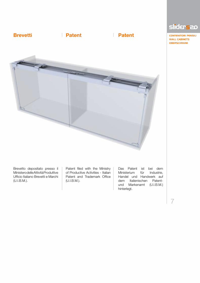
Brevetti Patent Patent
Brevetto depositato presso il Ministero delle Attività Produttive Ufficio Italiano Brevetti e Marchi (U.I.B.M.).
Patent filed with the Ministry of Productive Activities - Italian Patent and Trademark Office (U.I.B.M.).
Das Patent ist bei dem Ministerium für Industrie, Handel und Handwerk auf dem Italienischen Patent- und Markenamt (U.I.B.M.) hinterlegt.

8
Il cliente riceverà una scatola contenente:
1 n. 1 binario di scorrimento superiore con carrelli per applicazione ante;
2 n. 1 binario di guida inferiore;
3 n. 2 alberi di trasmissione.
PER OGNI ANTAC n. 1+1 regolatori per anta.
PER OGNI MECCANISMOF n. 4 paracolpi autoadesivi,
n. 1 chiave esagonale da 3 mm;N n. 2 angolari per supporto
binario superiore (solo versione 1 e 2), n. 4 viti TC;P n. 2 braccetti superiori e
n. 2 inferiori per alberi di trasmissione, n. 1 chiave esagonale da
2,5 mm.
The customer will receive a box containing:
1 1 no. upper sliding track complete with
carriages for doors;2 1 no. lower guide runner;3 2 no. connecting rods.
FOR EACH DOORC 1+1 no. door adjuster
blocks.
FOR EACH MECHANISMF 4 no. adhesive buffers,
1 no. 3 mm allen key;N 2 no. support brackets for
upper track (for versions 1 and 2 only),
4 no. TC screw;P 2 no. sets of upper and
lower bracket arms for connecting rods, 1 no. 2.5 mm allen key.
Dem Kunden wird eine Packung mit folgendem Material geliefert:
1 n. 1 obere Schiene mit Laufwagen für den Zusammenbau mit den Türen;
2 n. 1 untere Führungsschiene;3 n. 2 Verbindungsstange.
FÜR JEDE TÜRC n. 1+1 Reglerpaare für Türen.
FÜR JEDEN MECHANISMUSF n. 4 selbstklebende Pfuffer,
n. 1 Sechskantschlüssel 3 mm;N n. 2 Winkel für die Stütze der
oberen Schiene (nur Version 1 und 2), n. 4 TC Schrauben; P n. 2 obere Arme und
n. 2 untere Arme für die Verbindungsstange,
n. 1 Sechskantschlüssel 2,5 mm.
Kit KitKit

9
CONTENITORI PENSILI
WALL CABINETS
OBERSCHRANK
x 1 x 1 x 4 x 2
x 1
x 1
1
2
3
P
C F N
x 1
x 1
x 1
x 1
x 1

10
Legenda codici
Legenda codici e specifiche necessarie per l’ordine.
Nella tabella sono presenti le va-riabili riguardanti la progettazione del contenitore sul quale appli-care la tipologia di Slider S20 prescelta.Sulla base di tali informazioni, Bortoluzzi Sistemi fornirà gli elaborati riguardanti le lavorazio-ni da eseguire sui pannelli.Ulteriori informazioni sono dispo-nibili sul sito internet www.bortoluzzi.com, dove è anche possibile effettuare una simulazione tridimensionale del contenitore finito o perfezionare l’ordine di acquisto.
LT LA HT HI HA SPA SPAM SPB SPC SPE SPI SAB SAE RM RAS
Larg
hezz
a to
tale
mob
ile (m
m)
Tota
l wid
th o
f cab
inet
(mm
)Ge
sam
tes
Schr
ankk
orpu
sbre
itenm
ass
(mm
)
Larg
hezz
a an
ta (m
m)
Wid
th o
f doo
r (m
m)
Türb
reite
(mm
)
Alte
zza
tota
le m
obile
(mm
)To
tal h
eigh
t of e
xter
ior o
f cab
inet
(mm
)Ge
sam
tes
Schr
ankk
orpu
shöh
enm
ass
(mm
)
Alte
zza
vano
inte
rno
mob
ile (m
m)
Heig
ht o
f int
erio
r of c
abin
et (m
m)
Inne
n Sc
hran
kkor
push
öhe
(mm
)
Alte
zza
anta
(mm
)He
ight
of d
oor (
mm
)Tü
rhöh
e (m
m)
Spes
sore
ant
a (m
m)
Thic
knes
s of
doo
r (m
m)
Türs
tärk
e (m
m)
Spes
sore
ant
a +
man
iglia
(mm
)Th
ickn
ess
of d
oor +
han
dle
(mm
)Tü
rstä
rke
+ G
riff (
mm
)
Spes
sore
bas
e (m
m)
Thic
knes
s of
bot
tom
pan
el (m
m)
Unte
re K
orpu
spla
ttens
tärk
e (m
m)
Spes
sore
cie
lo (m
m)
Thic
knes
s of
top
pane
l (m
m)
Ober
e Ko
rpus
plat
tens
tärk
e (m
m)
Spes
sore
spa
lla e
ster
na (m
m)
Thic
knes
s of
sid
e pa
nel (
mm
)Se
iten
Korp
usst
ärke
(mm
)
Spes
sore
spa
lla c
entra
le (m
m)
Thic
knes
s of
cen
tre p
anel
(mm
)M
ittel
seite
Kor
puss
tärk
e (m
m)
Sorm
onto
ant
a su
bas
e (m
m)
Supe
rimpo
sitio
n of
doo
r on
botto
m p
anel
(mm
)Tü
r vor
Unt
erbo
den
(mm
)
Sorm
onto
ant
a su
spa
lla e
ster
na (m
m)
Supe
rimpo
sitio
n of
doo
r on
side
pan
el (m
m)
Tür v
or A
usse
nsei
ten
(mm
)
Rien
tro m
anig
lia d
al b
ordo
ant
a (m
m)
Rece
ss o
f han
dle
from
edg
e of
doo
r (m
m)
Griff
abst
and
von
seitl
iche
r Kan
te (m
m)
Rien
tro a
nta
dalla
stru
ttura
(mm
)Re
cess
of d
oor f
rom
stru
ctur
e (m
m)
Türa
bsta
nd v
on S
trukt
ur (m
m)
CodelegendeLegend of codes
Legend of the necessary codes and specifications for order.
This table includes the vari-ables required to design the piece of furniture to which theselected Slider system ap-plies.Based on this information, Bortoluzzi Sistemi will pro-vide detailed information on the drilling and machining re-quirements for the furniture panels and doors.Additional information is avail-able on the Website www.bortoluzzi.com, where you can view a 3D simulation of the finished piece of furniture or define a purchase order.
Codelegende und nötige Details für die Bestellung.
Diese Tabelle listet die Variablen auf, die zum Entwurf des Mö-belstückes für die Einsetzungdes ausgewählten Slider-Sys-tems notwendig sind.Aufgrund dieser Informationen wird Bortoluzzi Sistemi Be-richte über die Bearbeitungen, die auf den Möbelplatten aus-zuführen sind, liefern.Weitere Informationen finden Sie auf der Webseite: www.bortoluzzi.com, wo eine 3D-Möbelsimulation zur Verfü-gung steht und ein Kaufauftrag erteilt werden kann.

11
CONTENITORI PENSILI
WALL CABINETS
OBERSCHRANK
HT
SPC
SPB
18
HA
152
62
SPA RAS
SPAM33
3
8 15.4
12
185
76
SPESPE SPI
LT
RM RMLA LA3 3
36- /2
4
SPI
SPESPE SPI
LT
SAESAE RMRM
LALA
39+ /2SAE-SPI
HT
SPC
SPB
*
4
HA
SAB
SPA
3
SPAM33
152
44
185
76
8 12.4
12
TIPOLOGIA 1 TIPOLOGIA 2
SPESPE SPI
LT
TIPOLOGIA 3
SAESAE RMRM
LALA4
39+ /2SAE-SPI
HT
SPC
SPB
HI
44
*
HA
SAB
3
SPAM33
8 12.4
12
185
76
SPA
60
16
COD. mm
LT ●
LA ●
HT ●
HI
HA ●
SPA ●
SPAM ●
SPB ●
SPC ●
SPE ●
SPI ●
SAB
SAC
SAE
RM ●
RAS ●
Type 1 Typ 1Tipologia 1
Apertura ante.
Door opening.
Türöffnung.
Tipologie Types Typen
12
COD. mm
LT ●
LA ●
HT ●
HI
HA ●
SPA ●
SPAM ●
SPB ●
SPC ●
SPE ●
SPI ●
SAB ●
SAC
SAE ●
RM ●
RAS
HT
SPC
SPB
18
HA
152
62
SPA RAS
SPAM33
3
8 15.4
12
185
76
SPESPE SPI
LT
RM RMLA LA3 3
36- /2
4
SPI
SPESPE SPI
LT
SAESAE RMRM
LALA
39+ /2SAE-SPI
HT
SPC
SPB
*
4
HA
SAB
SPA
3
SPAM33
152
44
185
76
8 12.4
12
TIPOLOGIA 1 TIPOLOGIA 2
SPESPE SPI
LT
TIPOLOGIA 3
SAESAE RMRM
LALA4
39+ /2SAE-SPI
HT
SPC
SPB
HI
44
*
HA
SAB
3
SPAM33
8 12.4
12
185
76
SPA
60
16
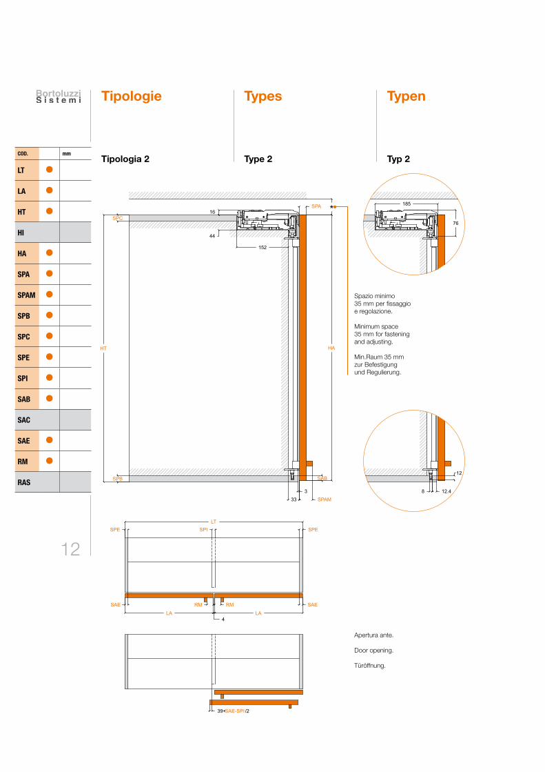
Type 2 Typ 2
Spazio minimo 35 mm per fissaggio e regolazione.
Minimum space 35 mm for fastening and adjusting.
Min.Raum 35 mmzur Befestigung und Regulierung.
Apertura ante.
Door opening.
Türöffnung.
Tipologia 2
Tipologie Types Typen

13
CONTENITORI PENSILI
WALL CABINETS
OBERSCHRANK
COD. mm
LT ●
LA ●
HT ●
HI ●
HA ●
SPA ●
SPAM ●
SPB ●
SPC ● 18-20
SPE ●
SPI ●
SAB ●
SAC
SAE ●
RM ●
RAS
HT
SPC
SPB
18
HA
152
62
SPA RAS
SPAM33
3
8 15.4
12
185
76
SPESPE SPI
LT
RM RMLA LA3 3
36- /2
4
SPI
SPESPE SPI
LT
SAESAE RMRM
LALA
39+ /2SAE-SPI
HT
SPC
SPB
*
4
HA
SAB
SPA
3
SPAM33
152
44
185
76
8 12.4
12
TIPOLOGIA 1 TIPOLOGIA 2
SPESPE SPI
LT
TIPOLOGIA 3
SAESAE RMRM
LALA4
39+ /2SAE-SPI
HT
SPC
SPB
HI
44
*
HA
SAB
3
SPAM33
8 12.4
12
185
76
SPA
60
16
Type 3 Typ 3
Spazio minimo 35 mm per fissaggio e regolazione.
Minimum space 35 mm for fastening and adjusting.
Min.Raum 35 mmzur Befestigung und Regulierung.
Apertura ante.
Door opening.
Türöffnung.
Tipologia 3


COME ORDINARE HOW TO ORDER BESTELLUNG
CONTENITORIPENSILI
WALL CABINETS
OBERSCHRANK

16
SPE SPE
LT
LI
LP
LI = LT-2*SPELP= LI-1 mm
Vedi pag. 11-12-13
Customised systems
Nach Maß
The S20 sliders can be cus-tomised, i.e., designed (on the basis of the variables listed on page 10) for installation on cabinets with internal width (LI) equal to the length of the slider rail (LP).
Die Slider S20 Beschläge kön-nen "nach Maß“ angefordert bzw. entworfen werden (dank der Variablen auf S. 10), um an Korpussen mit einem lichten Innenmaß (LI) gleich der Schie-nenlänge (LP) installiert zu wer-den.
I meccanismi Slider S20 pos-sono essere richiesti “su misu-ra”, cioé progettati (grazie alle variabili di pag. 10) per essere installati su contenitori con luce interna (LI) pari alla lunghezza dei binari (LP).
Su misura
LI = LT-2*SPE
LP = LI-1 mm
Vedi pagg. 11, 12 e 13.
See pages 11, 12 and 13.
Siehe S. 11, 12 und 13.
MONTAGGIOE REGOLAZIONI
ASSEMBLY ANDADJUSTMENTS
MONTAGE UNDREGULIERUNG
CONTENITORIPENSILI
WALL CABINETS
OBERSCHRANK
18
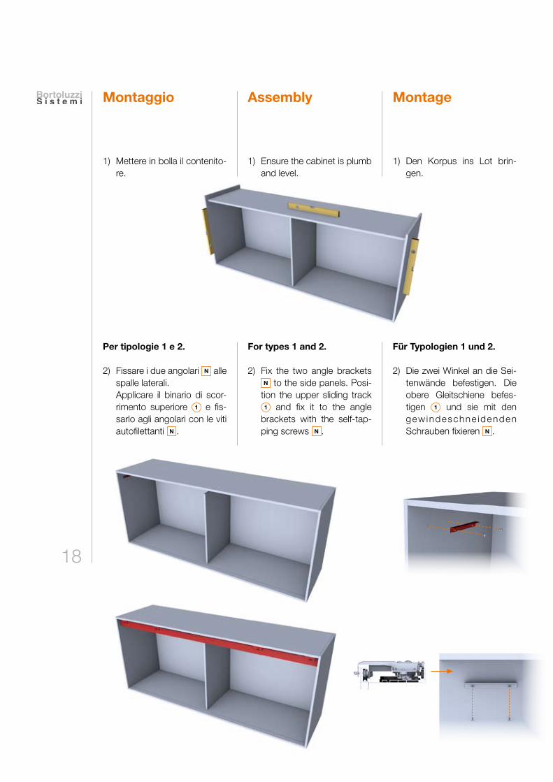
1) Mettere in bolla il contenito-re.
1) Ensure the cabinet is plumb and level.
1) Den Korpus ins Lot brin-gen.
Per tipologie 1 e 2.
2) Fissare i due angolari N alle spalle laterali.
Applicare il binario di scor-rimento superiore 1 e fis-sarlo agli angolari con le viti autofilettanti N .
For types 1 and 2.
2) Fix the two angle bracketsN to the side panels. Posi-
tion the upper sliding track 1 and fix it to the angle
brackets with the self-tap-ping screws N .
Für Typologien 1 und 2.
2) Die zwei Winkel an die Sei-tenwände befestigen. Die obere Gleitschiene befes-tigen 1 und sie mit den gew indeschne idenden Schrauben fixieren N .
Montaggio MontageAssembly

19
CONTENITORI PENSILI
WALL CABINETS
OBERSCHRANK
3) Inserire il binario di guida inferiore 2 nella base (se necessario incollare).
3) Insert the lower guide track 2 into the bottom panel.
Use adhesive if required.
3) Die untere Schiene 2 in den Unterboden einfügen (wenn nötig einkleben).
Per tipologia 3.
2) Applicare il binario di scor-rimento superiore 1 e fis-sarlo al cielo con viti TC.
For type 3.
2) Position the upper sliding track 1 and fix it to the top panel with woodscrews.
Für Typologie 3.
2) Die obere Schiene befestigen 1 und sie oben mit TC (Stern-
kopf) Schrauben fixieren.
20
B BA A
A B
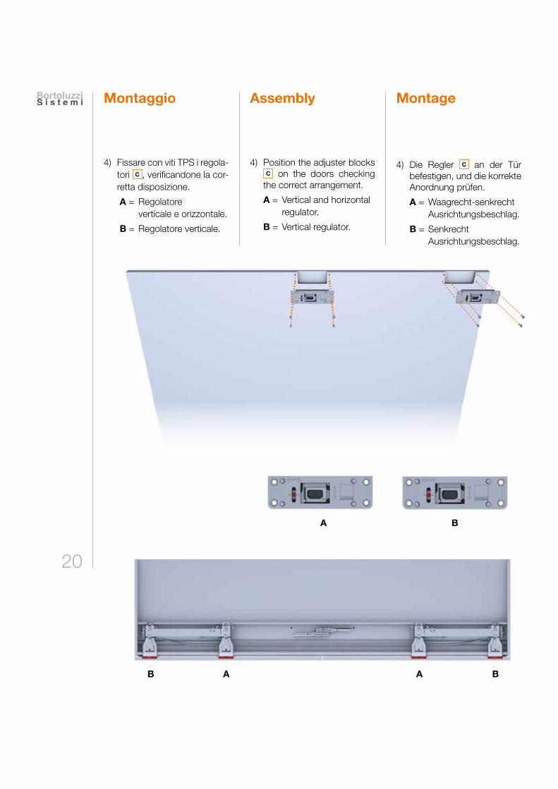
4) Fissare con viti TPS i regola-tori C , verificandone la cor-retta disposizione.
A = Regolatore verticale e orizzontale.
B = Regolatore verticale.
4) Position the adjuster blocks C on the doors checking
the correct arrangement.
A = Vertical and horizontal regulator.
B = Vertical regulator.
4) Die Regler C an der Tür befestigen, und die korrekte Anordnung prüfen.
A = Waagrecht-senkrecht Ausrichtungsbeschlag.
B = Senkrecht Ausrichtungsbeschlag.
Montaggio MontageAssembly

21
CONTENITORI PENSILI
WALL CABINETS
OBERSCHRANK
Fig. 1Abb. 1
Fig. 2Abb. 2
Nel caso si siano ricevute le tra-smissioni preassemblate, pas-sare al punto 7.
5) Accorciare i profili 3 a mi-sura (L) in base alle seguenti formule:
• Per i pensili di tipo 1 L=HT-SPC-SPB-156,4 mm• Per i pensili di tipo 2 L=HT-SPB-138,4 mm• Per i pensili di tipo 3 L=HI+SPC-94,5 mm
6) Assemblare i profili tagliati a misura con i braccetti P per formare le trasmissioni (Fig. 1). Porre attenzione a mantenere i braccetti in bat-tuta sul profilo (Fig. 2).
If the connecting rod systems have been pre-assembled, skip to point 7.
5) Cut the connecting rod 3 to length (L) using the fol-lowing formulae:
• For type 1 wall units L=HT-SPC-SPB-156.4 mm• For type 2 wall units L=HT-SPB-138.4 mm• For type 3 wall units L=HI+SPC-94.5 mm
6) Assemble the cut lengths to the bracket arms P to make up the connecting rod systems (Fig. 1). Ensure that the connecting rod is fully located into the bracket arms (Fig. 2).
Im Falle dass die Verbindungsstan-ge vormontiert geliefert worden ist, zu Punkt 7 übergehen.
5) Die Profile gemäß 3 den fol-genden Formeln auf Mass (L) kürzen:
• Für die Hängeschränke des Typs 1
L=HT-SPC-SPB-156,4 mm• Für die Hängeschränke
des Typs 2 L=HT-SPB-138,4 mm• Für die Hängeschränke
des Typs 3 L=HI+SPC-94,5 mm
6) Die auf Maß zugeschnittenen Profile mit den Auslenkarmen montieren P um die Verbin-dungsstange zu bilden (Abb. 1). Beachten dass die Auslen-karme ohne Spiel auf das Pro-fil montiert werden (Abb. 2).
Trasmissione destra.
Right connecting rod system.
Rechte Übertragung.
Trasmissione sinistra.
Left connecting rod system.
Linke Übertragung.

22
7) Estrarre una coppia di car-relli fino a totale apertura e applicare la corrispondente anta.
7) Move one pair of carriages until it is fully open and place the corresponding door into position.
7) Ein paar Laufwagen bis zur vollkommenen Öffnung her-ausziehen und die entspre-chende Tür befestigen.
Montaggio MontageAssembly

23
CONTENITORI PENSILI
WALL CABINETS
OBERSCHRANK
8) Wichtig! Die Tür mit der Sechskantschraube fixieren F .
9) Die Verbindungsstange einsetzen, indem man die Rolle in die obere Schiene einschiebt (durch den an den äußeren Enden ausge-führten Freilassungen), und anschliessend die Plas-tikkufe in die untere Füh-rungsschiene einschiebt.
8) Important! Fix the door onto the carriages using the 3 mm allen key F .
9) Insert the connecting rod assembly, sliding the wheel into the upper track through the access slots at the end of the track and then loca-ting the runner in the lower guide.
8) Importante! Bloccare l’anta con chiave esagona-le F .
9) Inserire l’albero di trasmis-sione, infilando la ruota nel binario di scorrimento su-periore (attraverso gli sca-richi eseguiti alle estremità) e successivamente il patti-no di plastica nel binario di guida inferiore.
1
2

24
11) Applicare sul lato interno delle ante i paracolpi auto-adesivi in dotazione F , in battuta sulla base del mo-bile.
11) Apply the adhesive deceler-ating components provided to the inside of the doors F , sealing the bottom in the cen-tre of the structure.
11) Auf der Innenseite der Tür-flügel die mitgelieferten selbstklebenden Puffer F
oben in der Mitte des Mö-belstücks anbringen.
10) Applicare l’albero di tra-smissione all’anta e fissare con viti TPS.
10) Position the connecting rod assembly on the door, and secure with woodscrews.
10) Die Verbindungsstange mit der Tür verbinden und mit den Holzschrauben fixieren.
Ripetere la procedura dal punto 7 al punto 10 per la seconda anta.
Repeat steps 7 to 10 for the second door.
Die Prozedur für die zweite Türe von Punkt 7 bis Punkt 10 wiederholen.
Montaggio MontageAssembly

25
CONTENITORI PENSILI
WALL CABINETS
OBERSCHRANK
13) Allo stesso modo, regolare la posizione verticale.
13) In the same way, adjust the vertical position.
13) In gleicher Weise die senk-rechte Lage regeln.
Ripetere le operazioni anche sulla seconda anta. Chiude-re le ante.
Repeat the operation on the second door. Close the doors.
Die Vorgänge auch auf der zweiten Türe wiederholen. Die Türen schliessen.
Regolazioni RegulierungAdjustments
12) Aprire completamente l’an-ta e metterla in bolla agen-do sui regolatori superiori nell’impronta di sinistra.
12) Completely open the door and level it adjusting the upper adjusters in the left slot.
12) Die Tür vollkommen öffnen und sie ins Lot bringen, in-dem man auf die oberen Regler in der linken Markie-rung einwirkt.

26
=
=
14) Se lo scuretto tra le ante non risultasse parallelo, agire sui regolatori verticali.
Attenzione: l’eventuale regolazione deve essere minima.
14) If the gap between the doors is not parallel, adjust it using the vertical adjust-ers.
Attention: any adjust-ment must be minimal.
14) Wenn der Spalt zwischen den Türen nicht parallel sein sollte, auf die senk-rechten Regler einwirken.
Achtung: die etwaige Regelung muss gering-fügig sein.
Regolazioni RegulierungAdjustments

27
CONTENITORI PENSILI
WALL CABINETS
OBERSCHRANK
3 mm
3 mm
4 mm
15) Regolare la larghezza degli scuretti tra ante e struttura agendo sul regolatore cen-trale nell’impronta di de-stra.
15) The doors can be adjusted horizontally by using the adjuster in the right hand slot in the central adjuster block.
15) Die Spaltenbreite zwischen den Türen und der Struktur einstellen, indem man auf den Reglern in der rechten Markierung einwirkt.

28
Per regolare lateralmente l’alli-neamento tra anta e struttura agire nel seguente modo:
A se nella parte superiore lo scuretto misura 3 mm e nel-la parte inferiore una quota minore, agire sulla regola-zione inferiore con la chiave esagonale da 2,5 mm P .
In order to adjust the gap between the door and the cabinet, please take the following action:
A If the gap at the top of the door is 3 mm and the gap at the bottom of the door is less than 3 mm, adjust the regula-tor on the lower bracket arm with a 2.5 mm allen key P .
m seitlich den Spalt zwischen Tür und Struktur einzustellen, folgendermaßen vorgehen:
A Wenn der Spalt im oberen Teil und im unteren Teil ein kleine-res Maß als 3 mm aufweist, mit dem 2,5 mm Sechskant-schlüssel die untere Regelung justieren P .
Regolazioni RegulierungAdjustments
< 3 mm
3 mm

29
CONTENITORI PENSILI
WALL CABINETS
OBERSCHRANK
B se nella parte superiore lo scuretto misura 3 mm e nella parte inferiore una quota maggiore, agire sulla regolazione superiore con la chiave esagonale da 2,5 mm P .
B If the gap at the top of the door is 3 mm and the gap at the bottom of the doors is more than 3 mm, adjust the regulator on the upper bracket arm with a 2.5 mm allen key P .
B Wenn der Spalt im oberen Teil und im unteren Teil ein größeres Maß als 3 mm aufweist, mit dem 2,5 mm Sechskantschlüssel die obe-re Regelung justieren P .
> 3 mm
3 mm

PANT.166 C
0% Cyan 64% Magenta 100% Yellow 0% Black
PANT.Black 7 C
0% Cyan 0% Magenta 15% Yellow 82% Black
PANT.Cool gray 7 C
PANT.158 U
PANT.Black 7 U
PANT.Cool gray 5 U
0% Cyan 0% Magenta 0% Yellow 37% Black
CONTENITORIA TERRA
FLOOR CABINETS
UNTERSCHRANK

32
Caratteristichetecniche
Composizione movimenti● Profili in alluminio: lega 6060T5 anodizzati
argento ARC10● Ruote di scorrimento:
cuscinetti per alta velocità rivestiti in materiale plastico
● Componenti di traslazione e regolazione: pressofusi
in zama primaria 13
Caratteristiche delle ante● Peso massimo per singola
anta = 20 Kg (uniformemente distribuito)● Larghezza: - minima 600 mm - massima 1500 mm● Altezza: massima 1200 mm● Spessore: - minimo 18 mm - massimo 45 mm (maniglia compresa)● Regolazione verticale dell’anta ± 4.5 mm● Regolazione orizzontale
dell’anta ± 3 mm
(per eventuali fuori misura, contattare la Bortoluzzi Sistemi).
● Materiale: a) legno o derivati; b) vetro con telaio in
alluminio (per verificare la fattibilità
contattare la Bortoluzzi Sistemi).
Tipologie aperture● Sono disponibili movimenti
con apertura di due ante uguali oppure di un’anta unica su vano a giorno
o cassetti.
● L’apertura delle ante è prevista tramite l’ausilio di maniglie posizionate al centro del mobile.
Technical features
Technische Eigenschaften
Mechanism elements● ARC10 silver anodised
6060T5 aluminium alloy profiles
● Nylon-coated rollers with high-velocity bearings
● Sliders and adjustment part in primary zamak 13
Doors features● Maximum weight for each
door = 20 Kg (Evenly distributed)● Width: - minimum 600 mm - maximum 1500 mm● Height: maximum 1200 mm● Thickness: - minimum 18 mm - maximum 45 mm (including handle)● Door vertical adjustment ± 4.5 mm● Door horizontal adjustment ± 3 mm
(For mechanisms out of the range contact Bortoluzzi Sistemi).
● Materials: a) wood or derived material b) glass with aluminium frame (for feasibility contact
Bortoluzzi Sistemi).
Zusammensetzung der Beschläge● Aluprofil: aus 6060T5
Legierung, eloxiert, Silber ARC10● Schieberollen:
plastikbezogene Hochgeschwindigkeitslager
● Einstell- und Verschiebungselemente:
aus 13-Zamakdruckguss
Eigenschaften der Türen● Max. Gewicht je Tür = 20 Kg (Gleichmäßig verteilt) ● Breite: min. 600 mm max. 1500 mm● Höhe: max. 1200 mm● Stärke: min. 18 mm max. 45 mm (inklusive Griff)● Vertikal Regulierung des
Blattes ± 4.5 mm● Horizontale Regulierung des Blattes ± 3 mm
(Bei Systemen außerhalb dieser Maße Bortoluzzi Sistemi kontaktieren).
● Material: a) Holz oder Holzprodukte; b) Glas mit Aluprofilen
umrahmt (für die Machbarkeit
Bortoluzzi Sistemi kontaktieren).
Öffnungstypen● Entweder Systeme mit zwei
gleich breiten Türen oder mit einer einzigen Tür, die sich auf einen offenen
Raum oder ein Fach öffnen.
● Die Öffnung der Türflügel erfolgt mithilfe von in der Mitte des Möbelstücks positionierten Griffen.
Openings types● Systems with two identical
doors, or single door opening onto an open shelving unit or a unit with drawers are available.
● The doors open with the use of handles placed in the
centre of the cabinet or wardrobe.
33
CONTENITORI A TERRA
FLOOR CABINETS
UNTERSCHRANK
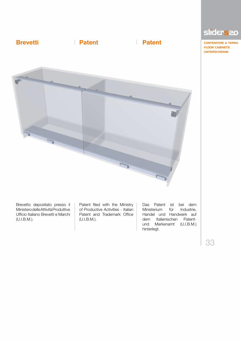
Brevetti Patent Patent
Brevetto depositato presso il Ministero delle Attività Produttive Ufficio Italiano Brevetti e Marchi (U.I.B.M.).
Patent filed with the Ministry of Productive Activities - Italian Patent and Trademark Office (U.I.B.M.).
Das Patent ist bei dem Ministerium für Industrie, Handel und Handwerk auf dem Italienischen Patent- und Markenamt (U.I.B.M.) hinterlegt.

34
Kit KitKit
Il cliente riceverà una scatola contenente:
1 n. 1 binario di scorrimento inferiore con carrelli per applicazione ante;
2 n. 1 binario di guida superiore (intero).
PER OGNI ANTAC n. 1+1 regolatori per anta.
PER OGNI MECCANISMOB n. 2 bilancieri guida
superiori;D n. 2 staffe superiori;E n. 2 carter copertura staffe
superiori;F n. 4 paracolpi autoadesivi,
n. 1 chiave esagonale da 3 mm.
LA QUANTITÀ DEGLI ELEMENTI SOTTO ELENCATI, DIPENDE DAL MECCANISMOA n. 4 / 6 / 8 clip per
fissaggio binario superiore.
The customer will receive a box containing:
1 1 no. lower sliding track complete with carriages for doors;
2 1 no. upper guide runner (in one or two sections).
FOR EACH DOORC 1+1 no. door adjuster
blocks.
FOR EACH MECHANISMB 2 no. guides for upper
runner;D 2 no. upper brackets;E 2 no. cover plates for
upper brackets;F 4 no. adhesive buffers,
1 no. 3 mm allen key.
THE QUANTITY OF THE FOLLOWING COMPONENTS WILL VARY ACCORDING TO THE LENGTH OF THE MECHANISMA no. Either 4, 6, or 8
fixing clips for upper guide runner.
Der Kunde wird eine Schachtel erhalten, die folgendes enthält:
1 n. 1 untere Schiene mit Laufwagen für den Zusammenbau mit den Türen;
2 n. 1 obere Führungsschiene
(ganz Teilen).
FÜR JEDE TÜRC n. 1+1 Reglerpaare für Türen.
FÜR JEDEN MECHANISMUSB n. 2 obere
Führungsausleger;D n. 2 obere Halterungen;E n. 2 Schutzkappen für die
oberen Halterungen;F n. 4 selbstklebende Pfuffer,
n. 1 Sechskantschlüssel 3 mm.
DIE MENGE DER ELEMENTE, DIE UNTEN BESCHRIEBEN WERDEN, IST VOM BESCHLAG ABHÄNGIGA n. 4/6/8 Klips für die
Befestigung der oberen Schiene.

35
CONTENITORI A TERRA
FLOOR CABINETS
UNTERSCHRANK
1
2
D E F
A B C
x 4 / 6 / 8 x 2 x 1
x 1x 1x 1 x 1
x 1
x 1
x 1

36
Codelegende und nötige Details für die Bestellung.
Legenda codici
Legenda codici e specifiche necessarie per l’ordine.
Nella tabella sono presenti le va-riabili riguardanti la progettazione del contenitore sul quale appli-care la tipologia di Slider S20 prescelta.Sulla base di tali informazioni, Bortoluzzi Sistemi fornirà gli elaborati riguardanti le lavorazio-ni da eseguire sui pannelli.Ulteriori informazioni sono dispo-nibili sul sito internet www.bortoluzzi.com, dove è anche possibile effettuare una simulazione tridimensionale del contenitore finito o perfezionare l’ordine di acquisto.
LT LA HT HI HA SPA SPAM SPB SPC SPE SPI SAC SAE RM RAS
Larg
hezz
a to
tale
mob
ile (m
m)
Tota
l wid
th o
f cab
inet
(mm
)Ge
sam
tes
Schr
ankk
orpu
sbre
itenm
ass
(mm
)
Larg
hezz
a an
ta (m
m)
Wid
th o
f doo
r (m
m)
Türb
reite
(mm
)
Alte
zza
tota
le m
obile
(mm
)To
tal h
eigh
t of i
nter
ior o
f cab
inet
(mm
)Ge
sam
tes
Schr
ankk
orpu
shöh
enm
ass
(mm
)
Alte
zza
vano
inte
rno
mob
ile (m
m)
Heig
ht o
f int
erio
r of c
abin
et (m
m)
Inne
n Sc
hran
kkor
push
öhe
(mm
)
Alte
zza
anta
(mm
)He
ight
of d
oor (
mm
)Tü
rhöh
e (m
m)
Spes
sore
ant
a (m
m)
Thic
knes
s of
doo
r (m
m)
Türs
tärk
e (m
m)
Spes
sore
ant
a +
man
iglia
(mm
)Th
ickn
ess
of d
oor +
han
dle
(mm
)Tü
rstä
rke
+ G
riff (
mm
)
Spes
sore
bas
e (m
m)
Thic
knes
s of
bot
tom
pan
el (m
m)
Unte
re K
orpu
spla
ttens
tärk
e (m
m)
Spes
sore
cie
lo (m
m)
Thic
knes
s of
top
pane
l (m
m)
Ober
e Ko
rpus
plat
tens
tärk
e (m
m)
Spes
sore
spa
lla e
ster
na (m
m)
Thic
knes
s of
sid
e pa
nel (
mm
)Se
iten
Korp
usst
ärke
(mm
)
Spes
sore
spa
lla c
entra
le (m
m)
Thic
knes
s of
cen
tre p
anel
(mm
)M
ittel
seite
Kor
puss
tärk
e (m
m)
Sorm
onto
ant
a su
cie
lo (m
m)
Supe
rimpo
sitio
n of
doo
r on
top
pane
l (m
m)
Tür v
or O
berp
latte
(mm
)
Sorm
onto
ant
a su
spa
lla e
ster
na (m
m)
Supe
rimpo
sitio
n of
doo
r on
side
pan
el (m
m)
Tür v
or A
usse
nsei
ten
(mm
)
Rien
tro m
anig
lia d
al b
ordo
ant
a (m
m)
Rece
ss o
f han
dle
from
edg
e of
doo
r (m
m)
Griff
abst
and
von
seitl
iche
r Kan
te (m
m)
Rien
tro a
nta
dalla
stru
ttura
(mm
)Re
cess
of d
oor f
rom
stru
ctur
e (m
m)
Türa
bsta
nd v
on S
trukt
ur (m
m)
CodelegendeLegend of codes
Legend of the necessary codes and specifications for order.
This table includes the vari-ables required to design the piece of furniture to which theselected Slider system ap-plies.Based on this information, Bortoluzzi Sistemi will pro-vide detailed information on the drilling and machining re-quirements for the furniture panels and doors.Additional information is avail-able on the Website www.bortoluzzi.com, where you can view a 3D simulation of the finished piece of furniture or define a purchase order.
Diese Tabelle listet die Variablen auf, die zum Entwurf des Mö-belstückes für die Einsetzungdes ausgewählten Slider-Sys-tems notwendig sind.Aufgrund dieser Informationen wird Bortoluzzi Sistemi Be-richte über die Bearbeitungen, die auf den Möbelplatten aus-zuführen sind, liefern.Weitere Informationen finden Sie auf der Webseite: www.bortoluzzi.com, wo eine 3D-Möbelsimulation zur Verfü-gung steht und ein Kaufauftrag erteilt werden kann.

37RM RM
LA LA3 34
SPESPE SPI
LT
TIPOLOGIA 4
14- /2SPI
35
44
HA
3
*
SPC
SPB
HI
HT
SPAM
SPA RAS
60
185
128
96
100
70 60
3
SPESPE SPI
LT
RM RMLA LA
4
17+ - /2SPISAE
38+SAE
SAE SAE
100
70
SPC
SPB
HI
HT
44
HA
*
60
185
3
SAC
SPAM
SPA
60
TIPOLOGIA 5
SPESPE SPI
LT
RM RMLA LA3 3
4
14- /2SPI
35
100
70
SPC
SPB
HI
HT
TIPOLOGIA 63
SAC
SPAM
44
HA
*
SPA RAS
60
60
185
TIPOLOGIA 7
SPESPE SPI
LT
RM RMLA LA
4
SAE SAE
17+ - /2SAE SPI
38+SAE
SPC
SPB
HI
HT
100
70
58
185
60
SPA3
93
125
93
125
93
125
SPAM
RAS
44
HA
3
*
COD. mm
LT ●
LA ●
HT ●
HI ●
HA ●
SPA ●
SPAM ●
SPB ●
SPC ●
SPE ●
SPI ●
SAB
SAC
SAE
RM ●
RAS ●
CONTENITORI A TERRA
FLOOR CABINETS
UNTERSCHRANK
TIPOLOGIA 4 TYPE 4 TYP 4
Spazio minimo 35 mm per fissaggio e regolazione.
Minimum space 35 mm for fastening and adjusting.
Min.Raum 35 mm zur Befestigung und Regulierung.
Apertura ante con guida superiore intera.
With one-piece upper runner: door opening.
Türöffnung mit durchgehender oberer Schiene.
Apertura ante con guida superiore spezzata.
With two-pieces upper runner.
Türöffnung mit geteilter oberer Schiene.
Tipologie Types Typen

38
TIPOLOGIA 5
RM RMLA LA3 3
4
SPESPE SPI
LT
TIPOLOGIA 4
14- /2SPI
35
44
HA
3
*
SPC
SPB
HI
HT
SPAM
SPA RAS
60
185
128
96
100
70 60
3
SPESPE SPI
LT
RM RMLA LA
4
17+ - /2SPISAE
38+SAE
SAE SAE
100
70
SPC
SPB
HI
HT
44
HA
*
60
185
3
SAC
SPAM
SPA
60
TIPOLOGIA 5
SPESPE SPI
LT
RM RMLA LA3 3
4
14- /2SPI
35
100
70
SPC
SPB
HI
HT
TIPOLOGIA 63
SAC
SPAM
44
HA
*
SPA RAS
60
60
185
TIPOLOGIA 7
SPESPE SPI
LT
RM RMLA LA
4
SAE SAE
17+ - /2SAE SPI
38+SAE
SPC
SPB
HI
HT
100
70
58
185
60
SPA3
93
125
93
125
93
125
SPAM
RAS
44
HA
3
*
TYPE 5 TYP 5
Spazio minimo 35 mm per fissaggio e regolazione.
Minimum space 35 mm for fastening and adjusting.
Min.Raum 35 mmzur Befestigung und Regulierung.
Apertura ante con guida superiore intera.
With one-piece upper runner: door opening.
Türöffnung mit durchgehender oberer Schiene.
Apertura ante con guida superiore spezzata.
With two-pieces upper runner.
Türöffnung mit geteilter oberer Schiene.
COD. mm
LT ●
LA ●
HT ●
HI ●
HA ●
SPA ●
SPAM ●
SPB ●
SPC ●
SPE ●
SPI ●
SAB
SAC ●
SAE ●
RM ●
RAS
Tipologie Types Typen

39
COD. mm
LT ●
LA ●
HT ●
HI ●
HA ●
SPA ●
SPAM ●
SPB ●
SPC ●
SPE ●
SPI ●
SAB
SAC ●
SAE
RM ●
RAS ●
TIPOLOGIA 6
RM RMLA LA3 3
4
SPESPE SPI
LT
TIPOLOGIA 4
14- /2SPI
35
44
HA
3
*
SPC
SPB
HI
HT
SPAM
SPA RAS
60
185
128
96
100
70 60
3
SPESPE SPI
LT
RM RMLA LA
4
17+ - /2SPISAE
38+SAE
SAE SAE
100
70
SPC
SPB
HI
HT
44
HA
*
60
185
3
SAC
SPAM
SPA
60
TIPOLOGIA 5
SPESPE SPI
LT
RM RMLA LA3 3
4
14- /2SPI
35
100
70
SPC
SPB
HI
HT
TIPOLOGIA 63
SAC
SPAM
44
HA
*
SPA RAS
60
60
185
TIPOLOGIA 7
SPESPE SPI
LT
RM RMLA LA
4
SAE SAE
17+ - /2SAE SPI
38+SAE
SPC
SPB
HI
HT
100
70
58
185
60
SPA3
93
125
93
125
93
125
SPAM
RAS
44
HA
3
*
TYPE 6 TYP 6
Spazio minimo 35 mm per fissaggio e regolazione.
Minimum space 35 mm for fastening and adjusting.
Min.Raum 35 mmzur Befestigung und Regulierung.
Apertura ante con guida superiore intera.
With one-piece upper runner: door opening.
Türöffnung mit durgehender oberen Schiene.
Apertura ante con guida superiore spezzata.
With two-pieces upper runner.
Türöffnung mit geteilter oberen Schiene.
CONTENITORI A TERRA
FLOOR CABINETS
UNTERSCHRANK

40
COD. mm
LT ●
LA ●
HT ●
HI ●
HA ●
SPA ●
SPAM ●
SPB ●
SPC ●
SPE ●
SPI ●
SAB
SAC
SAE ●
RM ●
RAS ●
TIPOLOGIA 7
SPESPE SPI
LT
RM RMLA LA
4
SAE SAE
17+ - /2SAE SPI
38+SAE
SPC
SPB
HI
HT
100
70
60
185
60
SPA3
93
125
SPAM
RAS
44
HA
3
*
Tipologie Types Typen
TIPOLOGIA 7 TYPE 7 TYP 7
Apertura ante con guida superiore intera.
With one-piece upper runner: door opening.
Türöffnung mit durchgehender oberer Schiene.
Apertura ante con guida superiore spezzata.
With two-pieces upper runner.
Türöffnung mit geteilter oberer Schiene.
Spazio minimo 35 mm per fissaggio e regolazione.
Minimum space 35 mm for fastening and adjusting.
Min.Raum 35 mmzur Befestigung und Regulierung.

CONTENITORIA TERRA
FLOOR CABINETS
UNTERSCHRANK
COME ORDINARE HOW TO ORDER BESTELLUNG

42
SPE SPE
LT
LI
LP
LI = LT-2*SPELP= LI-1 mm
Vedi pag. 37-38-39-40
LI = LT-2*SPE
LP = LI-1 mm
Vedi pagg. 37, 38, 39 e 40.
See pages 37, 38, 39 and 40.
Siehe S. 37, 38, 39 und 40.
Customised systems
Nach Maß
The S20 sliders can be cus-tomised, i.e., designed (on the basis of the variables listed on page 36) for installation on cabinets with internal width (LI) equal to the length of the slider rail (LP).
Die Slider S20 Beschläge kön-nen "nach Maß“ angefordert bzw. entworfen werden (dank der Variablen auf S. 36), um an Korpussen mit einem lichten In-nenmaß (LI) gleich der Schienen-länge (LP) installiert zu werden.
Su misura
I meccanismi Slider S20 pos-sono essere richiesti “su misu-ra”, cioé progettati (grazie alle variabili di pag. 36) per essere installati su contenitori con luce interna (LI) pari alla lunghezza dei binari (LP).

CONTENITORIA TERRA
FLOOR CABINETS
UNTERSCHRANK
MONTAGGIOE REGOLAZIONI
ASSEMBLY ANDADJUSTMENTS
MONTAGE UNDREGULIERUNG

44
1) Mettere in bolla il contenito-re.
1) Ensure the cabinet is plumb and level.
1) Den Behälter ins Lot brin-gen.
2) Applicare al cielo le clip in plastica A con viti TC.
2) Fix the plastic clips A to the top panel with wood-screws.
2) Die Plastikklips A nach oben mit TC (Sternkopf) Schrauben befestigen.
MontageAssemblyMontaggio

45
CONTENITORI A TERRA
FLOOR CABINETS
UNTERSCHRANK
3) Applicare il binario di scorri-mento inferiore 1 e fissarlo con viti autofilettanti TPS.
3) Position the sliding track 1 and fix it with self-tapping screws.
3) Die untere Schiene befes-tigen 1 und sie mit den gew indeschne idenden Schrauben (TPS) fixieren.
4) Inserire i bilancieri B nella guida del binario superiore 2 .
4) Insert the runners B in the track 2 .
4) Die Ausleger B in die Füh-rung der oberen Schiene einsetzen 2 .

46
5) Inserire la guida superiore 2 nelle clip e fissarla con
viti TC.
5) Insert the upper track 2 into the clips and secure it with woodscrews.
5) Die obere Führung 2 in die Klammern einsetzen und sie mit TC Schrauben be-festigen.
MontageAssemblyMontaggio

47
B BA A
A B
CONTENITORI A TERRA
FLOOR CABINETS
UNTERSCHRANK
6) Fissare con viti TPS i regola-tori C , verificandone la cor-retta disposizione.
A = Regolatore verticale e orizzontale.
B = Regolatore verticale.
4) Position the adjuster blocks C on the doors checking
the correct arrangement.
A = Vertical and horizontal regulator.
B = Vertical regulator.
4) Die Regler C an der Tür befestigen, und die korrekte Anordnung prüfen.
A = Waagrecht-senkrecht Ausrichtungsbeschlag.
B = Senkrecht Ausrichtungsbeschlag.

48
7) Fissare la staffa superiore D con viti TC.
7) Fix the upper bracket D with woodscrews.
7) Die obere Halterung D mit TC Schrauben befestigen.
8) Estrarre una coppia di car-relli fino a totale apertura.
8) Move one pair of carriages until it is fully open.
8) Einen der Laufwagen bis zur vollkommenen Öffnung herausziehen.
MontageAssemblyMontaggio

49
CONTENITORI A TERRA
FLOOR CABINETS
UNTERSCHRANK
9) Applicare l’anta inserendo prima il perno del bilancie-re superiore nel foro della staffa e poi i perni dei carrelli inferiori nei regolatori.
9) Position the door by first lo-cating the pin on the upper guide into the hole in the bracket and then the pins of the lower carriages into their holes in the adjuster blocks.
9) Die Tür befestigen, indem man vorher den Bolzen des oberen Auslegers in das Loch des Halters einsetzt, und danach die Bolzen der unteren Wagen in den Reg-lern einsetzt.
10) Importante! Bloccare l’anta con chiave esagona-le F .
10) Important! Fix the door onto the carriages using the 3 mm allen key F .
10) Die Türen mit den Sechs-kantschrauben fixieren F .
Ripetere la procedura dal punto 8 al punto 10 per la seconda anta.
Repeat the procedure from point 8 to point 10 for the second door.
Die Montage für die zweite Tür von Punkt 8 bis Punkt 10 wiederholen.

50
11) Coprire le staffe superiori con i carter E .
11) Clip the cover plate E onto the upper bracket.
11) Die oberen Halterungen mit den Schutzkappen verse-hen E .
12) Applicare sul lato interno delle ante i paracolpi auto-adesivi in dotazione F , in battuta su base e cielo al centro del mobile.
12) Apply the adhesive decel-erating components pro-vided to the inside of the doors F , sealing the bot-tom and top in the centre of the structure.
12) Auf der Innenseite der Tür-flügel die mitgelieferten selbstklebenden Puffer F
oben und unten in der Mit-te des Möbelstücks anbrin-gen.
MontageAssemblyMontaggio

51
CONTENITORI A TERRA
FLOOR CABINETS
UNTERSCHRANK
Ripetere le operazioni anche sulla seconda anta. Chiude-re le ante.
Repeat the operation on the other door also. Close the doors.
Die Vorgänge auch auf der zweiten Tür wiederholen. Die Türen schliessen.
13) Aprire completamente l’an-ta e metterla in bolla agen-do sui regolatori inferiori nell’impronta di destra.
13) Completely open the door and level it by adjusting the lower regulators in the rightslot.
13) Die Tür vollkommen öffnen und sie ins Lot bringen, in dem man die unteren Reg-ler in der rechten Markie-rung justiert.
Regolazioni RegulierungAdjustments
14) Allo stesso modo, regolare la posizione verticale.
14) In the same way, adjust the vertical position.
14) In gleicher Weise die senk-rechte Lage justieren.

52
=
=
15) Se lo scuretto tra le ante non risultasse parallelo, agire sui regolatori verticali.
Attenzione: l’eventuale regolazione deve essere minima.
15) If the gap between the doors is not parallel, adjust it using the vertical adjust-ers.
Attention: any adjust-ment must be minimal.
15) Wenn der Spalt zwischen den Türen nicht parallel sein sollte, die senkrechten Regler justieren.
Achtung: die etwaige Regelung muss gering-fügig sein.
Regolazioni RegulierungAdjustments

53
CONTENITORI A TERRA
FLOOR CABINETS
UNTERSCHRANK
16) Regolare la larghezza degli scuretti tra ante e struttura agendo sul regolatore cen-trale nell’impronta di sini-stra.
16) The doors can be adjusted horizontally by using the regulator in the left hand slot in the central adjuster block.
16) Die Spaltenbreite zwischen den Türen und dem Korpus einstellen, indem man den Regler in der linken Markie-rung justiert.
3 mm
3 mm
4 mm

54
17) Per regolare lateralmente l’allineamento tra anta e struttura, agire sulla staffa superiore fissata all’anta nel seguente modo:
A allentare la vite di fissag-gio;
B agire sull’eccentrico posto sotto la vite;
C chiudere la vite allentata al punto A.
17) In order to change the gap between the door and the cabinet, use the adjust-ment in the upper door bracket as follows:
A loosen the fixing screw;B Adjust the cam below the
fixing screw;C Re-tighten the fixing screw.
17) Um seitlich den Spalt der Tür und dem Korpus einzu-stellen wie folgt die oberer Halterung, die an der Tür befestigt ist, justieren:
A die Halteschraube lockern;B auf den Exzenter unter der
Schraube einwirken;C die bei Punkt A gelockerte
Schraube wieder festzie-hen.
Regolazioni RegulierungAdjustments

55
Note

56
Note

PuliziaLa pulizia dei componenti deve essere eseguita con acqua e sa-pone mediante un panno mor-bido. Evitare prodotti contenenti solventi e componenti abrasivi.
SmaltimentoUna volta dismesso, il prodotto e i suoi componenti non vanno dispersi nell’ambiente, ma con-feriti ai sistemi pubblici di smal-timento.
NotaL’Azienda produttrice si riserva il diritto di apportare modifiche tecniche senza preavviso.
CleaningCleaning the components must be executed using soap and water with a soft cloth. Avoid using products containing solvents and abrasive products.
DisposalThe products and its components must not be disposed of in the environment; for disposal, please use public disposal systems.
NoteThe manufacturer reserves the right to modify any product without prior notice.
ReinigungDie Reinigung der Teile muss mit Wasser, Seife und einem wei-chen Tuch erfolgen. Keine Pro-dukte mit Lösungsmitteln oder Schleifmittel verwenden.
EntsorgungDie Produkte und die Produkttei-le, die nicht mehr eingesetzt wer-den, sollen nicht in die Umwelt gelangen, sondern an den geeig-neten Stellen entsorgt werden.
HinweisDer Hersteller behält sich das Recht vor, Änderungen an den Produkten ohne vorherige An-kündigung vorzunehmen.

5029
CTC
0AS
T.2
(06-
2012
)
Bortoluzzi Sistemi spaVia Caduti 14.IX.44, 4532100 BELLUNO - Italy
Tel. + 39 0437.930866 r.a.Fax + 39 [email protected]
www.bortoluzzi.com