Motor Control Center Type 5600 Series Underwriters ...pub/@electrical/documents/cont… · Motor...
15
RP04304010E For more information visit: www.cutler-hammer.eaton.com Motor Control Center Type 5600 Series Renewal Parts ITE, Gould, Telemecanique and ITE Rowan MCCs New Information Description Page Motor Control Center Type 5600 Series Distributor Ordering Instructions . . . . . . . . . . . . . . . . . . . . . . . . . . . . . . . . . . 2 Procedure for Identifying MCC Renewal Units and Parts . . . . . . . . . . . . . . . 2 Identifying Motor Control Center Type . . . . . . . . . . . . . . . . . . . . . . . . . . . . . . 3 Identification by Original MCC — ITE Rowan, Gould and Telemecanique. . . . . . . . . . . . . . . . . . . . . . . . . . . . . 3 5600 Series Product Description . . . . . . . . . . . . . . . . . . . . . . . . . . . . . . . . . . . 4 Replacement Starter Units . . . . . . . . . . . . . . . . . . . . . . . . . . . . . . . . . . . . . . . . 5 – 9 Unit Options . . . . . . . . . . . . . . . . . . . . . . . . . . . . . . . . . . . . . . . . . . . . . . . . . . . 10 – 12 Replacement Feeder Units . . . . . . . . . . . . . . . . . . . . . . . . . . . . . . . . . . . . . . . . 13 Unit Parts . . . . . . . . . . . . . . . . . . . . . . . . . . . . . . . . . . . . . . . . . . . . . . . . . . . . . . 14 – 15 Underwriters Laboratories Label Eaton’s Cutler-Hammer Type 5600 Series Motor Control Center (MCC) units have been designed and tested to meet ULT Standard 845, where applicable. Accordingly, all standard electrical devices will be UL listed or recognized. UL MCC unit labels cannot be supplied if special non-UL listed devices are required by order specifications. Design includes NEMAT 1 gasketed unit. An ongoing temperature and short circuit design test program as required by UL 845 ensures a quality product that meets the latest safety codes.
Transcript of Motor Control Center Type 5600 Series Underwriters ...pub/@electrical/documents/cont… · Motor...

RP04304010E For more information visit: www.cutler-hammer.eaton.com
Motor Control Center
Type 5600 Series
Renewal Parts
ITE, Gould, Telemecanique and ITE Rowan MCCs
New Information
Description Page
Motor Control Center Type 5600 Series
Distributor Ordering Instructions . . . . . . . . . . . . . . . . . . . . . . . . . . . . . . . . . .
2
Procedure for Identifying MCC Renewal Units and Parts . . . . . . . . . . . . . . .
2
Identifying Motor Control Center Type . . . . . . . . . . . . . . . . . . . . . . . . . . . . . .
3
Identification by Original MCC — ITE Rowan, Gould and Telemecanique. . . . . . . . . . . . . . . . . . . . . . . . . . . . .
3
5600 Series Product Description . . . . . . . . . . . . . . . . . . . . . . . . . . . . . . . . . . .
4
Replacement Starter Units . . . . . . . . . . . . . . . . . . . . . . . . . . . . . . . . . . . . . . . .
5
–
9
Unit Options . . . . . . . . . . . . . . . . . . . . . . . . . . . . . . . . . . . . . . . . . . . . . . . . . . .
10
–
12
Replacement Feeder Units . . . . . . . . . . . . . . . . . . . . . . . . . . . . . . . . . . . . . . . .
13
Unit Parts . . . . . . . . . . . . . . . . . . . . . . . . . . . . . . . . . . . . . . . . . . . . . . . . . . . . . .
14
–
15
Underwriters Laboratories Label
Eaton’s Cutler-Hammer Type 5600 Series Motor Control Center (MCC) units have been designed and tested to meet UL
T
Standard 845, where applicable. Accordingly, all standard electrical devices will be UL listed or recognized. UL MCC unit labels cannot be supplied if special non-UL listed devices are required by orderspecifications.
Design includes NEMA
T
1 gasketed unit. An ongoing temperature and short circuit design test program as required by UL 845 ensures a quality product that meets the latest safety codes.

RP04304010E For more information visit: www.cutler-hammer.eaton.com
Renewal Parts
Effective: August 2003 Page
3
Motor Control Center Type 5600 Series
Identifying Motor Control Center Type
In most cases, it is possible to identify MCC design by handle type, starter type, stab, bucket or door width.
Table 1. Identifying Motor Control Center Type
Identification by Original MCC — ITE Rowan, Gould and Telemechanique
ITE/Gould MCC
Old 5600 Series Stab
Gould Handle Mechanisms Cover Plate
Telemecanique Starter Unit
MCCType
Type of HandleMechanism
Original MCCStarter Type
Bucket WidthInches (mm)
Door WidthInches (mm)
Starter Type (Installed in New Unit)
ITE
T
Rowan 5600 Lever/Rotating ITE 5600 13-3/4 (349.3) Approx. 15-5/8 (397.0) ITE Siemens
T
Gould
T
Lever/Rotating Gould 13-3/4 (349.3) Approx. 15-5/8 (397.0) Gould Siemens
Telemecanique
T
Rotating Telemecanique 13-3/4 (349.3) Approx. 15-5/8 (397.0) Telemecanique Telemecanique

For more information visit: www.cutler-hammer.eaton.com RP04304010E
Renewal Parts
Page
4
Effective: August 2003
Motor Control Center Type 5600 Series
New 5600 SeriesProduct Description
All control units, removable or fixed mounted, are assembled with Cutler-Hammer components of proven safety, quality and reliability. All com-ponents are wired in accordance with NEMA and UL
standards. Specifically designed bus stabs, insertion guides, handle mechanisms and safety inter-locks are added to form a standardized plug-in cell that meets the highest safety standards.
Unit design includes NEMA 1 gasketed. An ongoing temperature and short circuit design test program as required by UL 845 ensures a quality product that meets the latest safety codes.
Underwriters Laboratories
The 5600 Series MCC units have been designed and tested to meet UL Standard 845, where applicable. Accordingly, all standard electrical devices will be UL listed or recognized. UL MCC unit labels cannot be supplied if special non-UL listed devices are required by order specifications.
Plug-in Unit Bus Stabs
A tin-plated copper alloy stab incorpo-rates the ultimate in mechanical simplicity to provide precise control of contact pressure on the bus. This ensures a positive connection yet permits easy unit insertion and with-drawal. Units are mounted on a glass-reinforced plastic insulation block which totally protects each stab and absolutely ensures positive alignment of the stab with the vertical bus. The insulation block is also an integral part of the phase-to-phase isolation system. Power wiring is welded to the stabs and assemblies are accurately matched to the electrical requirements of each individual unit which are pro-vided in units up to 250 ampere ratings.
UL 845 Certified Stab Assembly
The Cutler-Hammer MCC Product Line used state-of-the-art 3D AutoCAD to develop and design the 5600 Series MCC bucket. This method not only provides the ability to make changes to one part of the assembly, which will automatically update the other effected parts, but it ensures the addi-tional quality for matching the parts during the assembly of the unit. This type of technology is just what the customer is demanding from their suppliers. The Cutler-Hammer business is leading our competition, providing nothing but the best for our customers.
The stab block has been moved to the top of the wrapper to eliminate cable flexing and possible damage and/or shorting, as well as decreased tempera-ture rise on the cable/stab configuration.
Figure 1. 5600 Series Design Concept
F-Frame Breaker
85 mmFreedom Starter
D7PR2Style Relays
Cutler-HammerMCC StyleTerminal Blocks
100 VA Transformer
Ground Clip
Stab Assembly

RP04304010E For more information visit: www.cutler-hammer.eaton.com
Renewal Parts
Effective: August 2003 Page
5
Motor Control Center Type 5600 Series
5600 Series Replacement Starter Units
How to Order
When ordering a replacement unit, you receive:
■
Series C
T
HMCP.
■
Freedom Starter.(See option codes for additional starter types offered.)
■
Unit options as specified.
■
New steel wrapper, door and handle mechanism.
■
New stabs.
■
UL 845 label.
Use the following steps for creating a catalog number for your specific application:
Step 1
Select the correct replacement unit from
Page 5 – 9
. When selecting, you need to know the following:
■
MCC type.
■
Class of Unit (FVNR; FVR; Solid-State Reduced Voltage Soft Start; 2-Speed,
1 Winding; or 2-Speed, 2 Winding).
■
Starter size or horsepower rating.
■
Protection device (breaker or fusible).
■
Service voltage.
■
Control voltage.
■
Space required.
Step 2
Verify required space is available.
Step 3
Create a catalog number by selecting Catalog Codes from the columns per the example given.
Step 4
Add modifications as required from the Unit Options on
Pages 10 – 12
. Space available determines allowable options.
Table 2. Catalog Numbering System Example
Table 3. Full Voltage Non-Reversing Combination Starter — HMCP
1
NEMA Size 5 available. Cable in/Cable out unit.
2
Consult factory.
NEMASize
Maximum Horsepower HMCP Size
Catalog Code
ServiceVoltage
Catalog Code
ControlVoltage
Catalog Code
Space Options Inches (mm)
Catalog Code208 V 240 V 380 V 480 V
1 0.5 1 3 7.5
0.33 1 3 7.5
1 2 5 10
1 3 7.5 10
3 7 15 30
GD206AGD206BGD206CGD206D
208240380480
BCDE
120208240380480
ABCDE
12 (304.8) High18 (457.2) High
SX
2 10 15 25 25 50
GD206E
208240380480
BCDE
120208240380480
ABCDE
12 (304.8) High18 (457.2) High
SX
3 25 30 50 50 100
GD206H
208240380480
BCDE
120208240380480
ABCDE
18 (457.2) High24 (609.6) High
CS
4 40 50 75 100 150
GD206L
208240380480
BCDE
120208240380480
ABCDE
18 (457.2) High24 (609.6) High
CS
5 6075
60100
125150
150200
250400
GD206PGD206R
208240380480
BCDE
120208240380480
ABCDE
48 (1219.2) High
S
12
Added OptionsUnit Size
C = CompactS = StandardX = Oversized
ControlVoltage
A = 120 VB = 208 VC = 240 VD = 380 VE = 480 V
Service Voltage
B = 208 VC = 240 VD = 380 VE = 480 V
G D 2 0 6 C E A S C12 P10 P34
HMCP Size
Size, hp and Amperes

For more information visit: www.cutler-hammer.eaton.com RP04304010E
Renewal Parts
Page
6
Effective: August 2003
Motor Control Center Type 5600 Series
5600 Series Replacement Starter Units
Table 4. Full Voltage Reversing Combination Starter — HMCP
Table 5. Full Voltage 2-Speed 1 Winding — Constant/Variable Torque — HMCP
1
1
For constant horsepower instead of constant/variable torque, see Option SV6 on
Page 12
.
Table 6. Full Voltage 2-Speed 2 Winding — Constant/Variable Torque — HMCP
2
2
For constant horsepower instead of constant/variable torque, see Option SV6 on
Page 12
.
NEMASize
Maximum Horsepower HMCP Size
Catalog Code
ServiceVoltage
Catalog Code
ControlVoltage
Catalog Code
Space Options Inches (mm)
Catalog Code208 V 240 V 380 V 480 V
1 0.5 1 3 7.5
0.33 1 3 7.5
1 2 510
1 3 7.5 10
3 7 15 30
GD216AGD216BGD216CGD216D
208240380480
BCDE
120208240380480
ABCDE
18 (457.2) High S
2 10 15 25 25 50 GD216E 208240380480
BCDE
120208240380480
ABCDE
24 (609.6) High S
3 25 30 50 50 100 GD216H 208240380480
BCDE
120208240380480
ABCDE
36 (914.4) High S
4 40 50 75 100 150 GD216L 208240380480
BCDE
120208240380480
ABCDE
36 (914.4) High S
NEMASize
Maximum Horsepower HMCP Size
Catalog Code
ServiceVoltage
Catalog Code
ControlVoltage
Catalog Code
Space Options Inches (mm)
Catalog Code208 V 240 V 380 V 480 V
1 0.5 1 3 7.5
0.33 1 3 7.5
1 2 510
1 3 7.5 10
3 7 15 30
GD946AGD946BGD946CGD946D
208240380480
BCDE
120208240380480
ABCDE
24 (609.6) High S
2 10 15 25 25 50 GD946E 208240380480
BCDE
120208240380480
ABCDE
30 (762.0) High S
3 25 30 50 50 100 GD946H 208240380480
BCDE
120208240380480
ABCDE
36 (914.4) High S
4 40 50 75 100 150 GD946L 208240380480
BCDE
120208240380480
ABCDE
42 (1066.8) High S
NEMASize
Maximum Horsepower HMCP Size
Catalog Code
ServiceVoltage
Catalog Code
ControlVoltage
Catalog Code
Space OptionsInches (mm)
Catalog Code208 V 240 V 380 V 480 V
1 0.5 1 3 7.5
0.33 1 3 7.5
1 2 510
1 3 7.5 10
3 7 15 30
GD956AGD956BGD956CGD956D
208240380480
BCDE
120208240380480
ABCDE
18 (457.2) High S
2 10 15 25 25 50 GD956E 208240380480
BCDE
120208240380480
ABCDE
24 (609.6) High S
3 25 30 50 50 100 GD956H 208240380480
BCDE
120208240380480
ABCDE
36 (914.4) High S
4 40 50 75 100 150 GD956L 208240380480
BCDE
120208240380480
ABCDE
36 (914.4) High S

RP04304010E For more information visit: www.cutler-hammer.eaton.com
Renewal PartsEffective: August 2003 Page 7
Motor Control Center Type 5600 Series
5600 Series Replacement Starter Units
IT06 — Intelligent Technologies IT. Solid-State Reduced Voltage Start — HMCPThe IT. solid-state reduced voltage starter uses SCRs when starting and a low impedance run circuit during operation. Solid- state starters have five (5) 24 Vdc inputs and two (2) relay outputs. Soft start units include a disconnect, starter, 24 Vdc power supply and 100 VA CPT.
Motor Service Factor (SF) Effect on IT. Starter Selection■ A 1.0 service factor motor may draw up to 1.00 x full load amperes.■ A 1.15 service factor motor may draw up to 1.15 x full load amperes.■ 15% more current. IT. starters are current rated devices. In some cases, a larger IT. SSRV starter must be supplied for
1.15 SF motors. See the maximum horsepower chart below.Note: Most motors used in industrial applications are 1.15 service factor (SF).
Table 7. Replacement IT. Soft Start Units
1 No stab — unit cable in/cable out.
Table 8. Full Voltage Non-Reversing — Fusible 2
2 Fuse clip ratings shown are based on Class RK1, 5 fuses.
ServiceFactor
Horsepower IT. Soft-Start Amperes
HMCPAmperes
CatalogCode
ServiceVoltage
CatalogCode
ControlVoltage
CatalogCode
Space Options Inches (mm)
CatalogCode
1.15 20 37 150 GD306A 480 E 120 A 18 (457.2) High S
40 66 GD306B 208 B
60 105 250 GD306C 240 C 30 (762.0) High
75 135 GD306D 380 D
125 180 400 1 GD306E 480 E 48 (1219.2) High
150 240 GD306F — —
200 304 GD306G — —
NEMASize
Maximum Horsepower Fuse ClipAmperes
Catalog Code
ServiceVoltage
Catalog Code
ControlVoltage
Catalog Code
Space OptionsInches (mm)
Catalog Code208 V 240 V 380 V 480 V 600 V
1 7.5 7.5 10 10 10 30 208240380480
BCDE
120208240380480
ABCDE
S
2 — 10
— 15
15 25
15 25
25—
30 60
208240380480
BCDE
120208240380480
ABCDE
S
3 — 25
20 30
30 50
40 50
50—
60100
208240380480
BCDE
120208240380480
ABCDE
S
4 — 50
— 50
— 60
60100
75100
100200
208240380480
BCDE
120208240380480
ABCDE
S
For more information visit: www.cutler-hammer.eaton.com RP04304010E
Renewal PartsPage 8 Effective: August 2003
Motor Control Center Type 5600 Series
5600 Series Replacement Starter Units
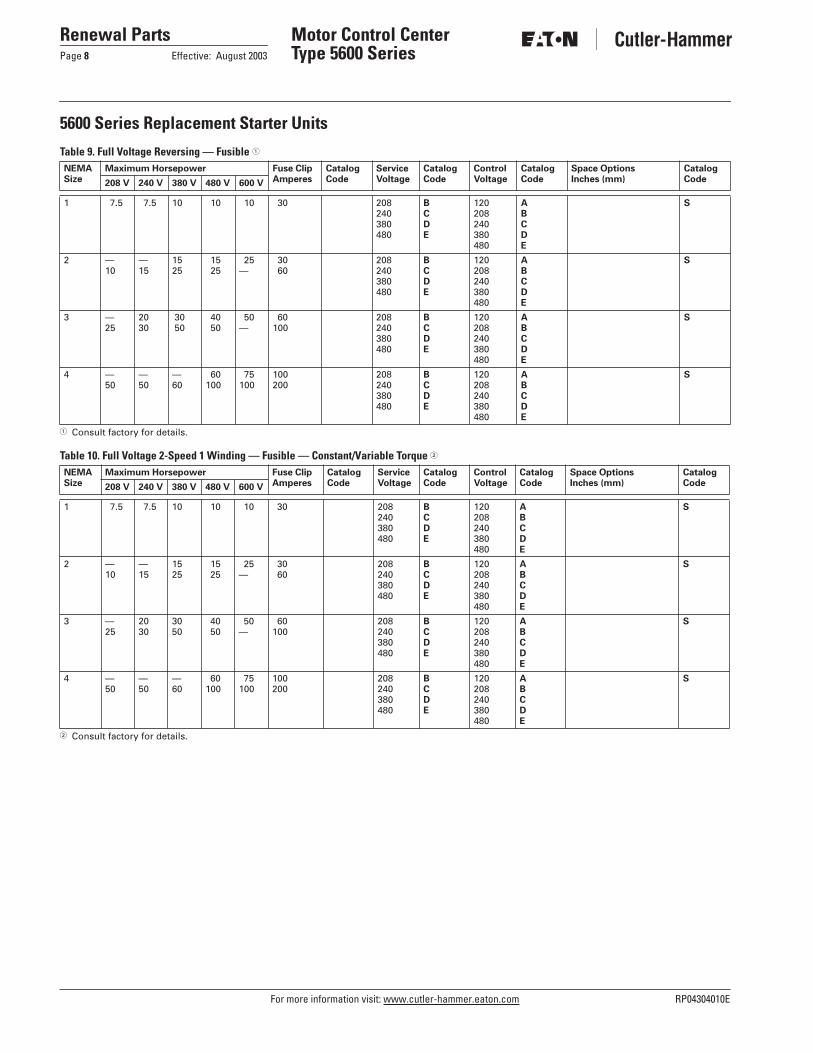
Table 9. Full Voltage Reversing — Fusible 1
1 Consult factory for details.
Table 10. Full Voltage 2-Speed 1 Winding — Fusible — Constant/Variable Torque 2
2 Consult factory for details.
NEMASize
Maximum Horsepower Fuse ClipAmperes
Catalog Code
ServiceVoltage
Catalog Code
ControlVoltage
Catalog Code
Space OptionsInches (mm)
Catalog Code208 V 240 V 380 V 480 V 600 V
1 7.5 7.5 10 10 10 30 208240380480
BCDE
120208240380480
ABCDE
S
2 —10
—15
1525
15 25
25—
30 60
208240380480
BCDE
120208240380480
ABCDE
S
3 —25
2030
30 50
40 50
50—
60100
208240380480
BCDE
120208240380480
ABCDE
S
4 —50
—50
—60
60100
75100
100200
208240380480
BCDE
120208240380480
ABCDE
S
NEMASize
Maximum Horsepower Fuse ClipAmperes
Catalog Code
ServiceVoltage
Catalog Code
ControlVoltage
Catalog Code
Space OptionsInches (mm)
Catalog Code208 V 240 V 380 V 480 V 600 V
1 7.5 7.5 10 10 10 30 208240380480
BCDE
120208240380480
ABCDE
S
2 —10
—15
1525
15 25
25—
30 60
208240380480
BCDE
120208240380480
ABCDE
S
3 —25
2030
3050
40 50
50—
60100
208240380480
BCDE
120208240380480
ABCDE
S
4 —50
—50
—60
60100
75100
100200
208240380480
BCDE
120208240380480
ABCDE
S

RP04304010E For more information visit: www.cutler-hammer.eaton.com
Renewal PartsEffective: August 2003 Page 9
Motor Control Center Type 5600 Series
5600 Series Replacement Starter Units
Table 11. Full Voltage 2-Speed 2 Winding — Fusible — Constant/Variable Torque 1
1 Consult factory for details.
NEMASize
Maximum Horsepower Fuse ClipAmperes
Catalog Code
ServiceVoltage
Catalog Code
ControlVoltage
Catalog Code
Space OptionsInches (mm)
Catalog Code208 V 240 V 380 V 480 V 600 V
1 7.5 7.5 10 10 10 30 208240380480
BCDE
120208240380480
ABCDE
S
2 —15
—15
1525
15 25
25—
30 60
208240380480
BCDE
120208240380480
ABCDE
S
3 —25
2030
3050
40 50
50—
60100
208240380480
BCDE
120208240380480
ABCDE
S
4 —50
—50
—60
60100
75100
100200
208240380480
BCDE
120208240380480
ABCDE
S

For more information visit: www.cutler-hammer.eaton.com RP04304010E
Renewal PartsPage 10 Effective: August 2003
Motor Control Center Type 5600 Series
5600 Series Unit Options
Table 12. Option Groups 1
1 Select your option suffix and attach it to the end of the catalog number.
Table 13. Option Suffix
2 Minimum unit size required (refer to Replacement Unit pages).3 Consult factory for spacing.4 Not available in 6 inches (152.4 mm).
Groups Description PageNumber
BCGK
Circuit Breaker OptionsControl Power Source OptionsGround Fault Protection OptionsStarter Type Options
10101010
MOPR
Metering OptionsOverload OptionsPilot Device OptionsRelay and Timer (Control, Voltage, Current) Options
11111112
SSVTU
Starter Contact OptionsVacuum Starter OptionsTerminal Block OptionsUnit Wiring Options
12121212
Suffix Description SpaceRequired 2
B — Breaker OptionsB10B11B12B13
Shunt Trip 120 Vac Wired to Terminal Blocks for Remote TrippingAuxiliary Switch Form C (1NO/1NC) Wired to Terminal BlocksForm C Bell Alarm Contact (1NO/1NC) Wired to Terminal BlocksUndervoltage Release
CCCC
B14B15B16B17B18
IQ Energy Sentinel — F Frame IQ Energy Sentinel — J Frame IQ Energy Sentinel — K Frame IQ Central Energy Display Thermal Magnetic Circuit Breaker Instead of HMCP
3
3
3
3
—
C — Control Power Source OptionsC10C11C12C13
Control Fuse Wired for Separate Source in Lieu of Control Power TransformerControl Fuse with Disconnect for Separate Source in Lieu of Control Power TransformerControl Power Transformer 100 VA for Sizes 1 and 2 Starters (Fused)Control Power Transformer 150 VA for Sizes 3 and 4 Starters (Fused)
CCC 4 C
C14C15C16C17C18
Control Power Transformer 100 VA with Interposing Relay for Size 5 Starters, FusedExtra 50 VA for Control Power TransformerExtra 100 VA for Control Power TransformerService Voltage Control, Fused in Lieu of Control Power TransformerFull Capacity Control Power Transformer for Size 5 Starters, Fused
CSSCC
G — Ground Fault Protection OptionsG10G11G12
Class 1 Ground Fault Protection — GRT1 Sizes 1 – 4Class 1 Ground Protection — GRT1 Sizes 5 – 6Ground Fault Test Panel
XXX
H — IT-EM OptionsH10 DSNAP Communication Module S
K — Starter Type OptionsK10K11K12K13
IT-EM Size 1 with Relays and Power Supply IncludedIT-EM Size 2 with Relays and Power Supply IncludedIT-EM Size 3 with Relays and Power Supply IncludedIT-EM Size 4 with Relays and Power Supply Included
SSSS
K15K16K17K18K19
A200 Size 1A200 Size 2A200 Size 3A200 Size 4A200 Size 5
SSSSS

RP04304010E For more information visit: www.cutler-hammer.eaton.com
Renewal PartsEffective: August 2003 Page 11
Motor Control Center Type 5600 Series
5600 Series Unit Options
Table 13. Option Suffix (Continued)
1 Minimum unit size required (refer to Replacement Unit pages).2 Customer to supply range of meter required.3 Available only with F2100, Advantage, Series 2100/5 Star, Freedom Unitrol, F10 Unitrol and Type W. Consult factory for specific size limitations.
Suffix Description SpaceRequired 1
M — Metering OptionsM10M11M12M13M14
Mini VoltmeterMini Ammeter with Current TransformerMini Elapsed Time MeterCurrent Transformer for Remote MeteringCurrent Transducer 4-20 mA Output
C 2
SC 2 SX
O — Overload OptionsO10O11O16O17O18O19O20
IQ 500 Solid-State Overload RelayIQ 500 Load Protection ModuleBell Alarm (1NO) WiredBi-Metallic Overload SubstitutionAdjustable A200 Overload SubstitutionOverload Relay Heater/Heater PackCEP7 Solid-State Overload Relay
——CCCCC
P — Pilot Device Options 3
P10P11P12P13
Red “RUN” Light Green “STOPPED” Light Amber “OVERLOAD TRIPPED” Light Green “RUN” Light
CCCC
P14P15P16P17
Red “STOPPED” Light Red “RUN” Push-to-Test Light Green “STOPPED” Push-to-Test Light Amber “OVERLOAD TRIPPED” Push-to-Test Light
CCCC
P18P19P20
Green “RUN” Push-to-Test Light Red “STOPPED” Push-to-Test Light Special Function Light
CCC
P30P31P32P33
“START” Pushbutton“STOP” Pushbutton“START/STOP” Pushbutton“ON” Pushbutton
CCCC
P34P35P36P37
“OFF” Pushbutton“ON/OFF” Pushbutton“FORWARD/REVERSE/STOP” Pushbutton“FAST/SLOW/STOP” Pushbutton
CCCC
P38P39P40P41
“FAST/OFF/SLOW” Pushbutton “HIGH/LOW/STOP” Pushbutton“HIGH/LOW/OFF” PushbuttonSpecial Function Pushbutton
CCCC
P50P51P52P53
“ON-OFF” Selector Switch“HIGH-LOW” Selector Switch“OFF-AUTO” Selector Switch“START-STOP” Selector Switch
CCCC
P54P55P56P57
“SLOW-FAST” Selector Switch“FORWARD-REVERSE” Selector SwitchSpecial Function 2-Position Selector Switch“HAND-OFF-AUTO” Selector Switch
CCCC
P58P59P60P61
“LOCAL-OFF-REMOTE” Selector Switch “FAST-OFF-SLOW” Selector Switch“HIGH-OFF-LOW” Selector SwitchSpecial Function 3-Position Selector Switch
CCCC
P62P63
“HIGH-LOW-OFF-AUTO” Selector SwitchSpecial Function 4-Position Selector Switch
CC

For more information visit: www.cutler-hammer.eaton.com RP04304010E
Renewal PartsPage 12 Effective: August 2003
Motor Control Center Type 5600 Series
5600 Series Unit Options
Table 13. Option Suffix (Continued)
1 Minimum unit size required (refer to Replacement Unit pages).2 Consult factory for spacing.
Suffix Description SpaceRequired 1
R — Relay and Timer OptionsR10R11R12R13
Auxiliary Control Relay 2-Pole (1NO/1NC) Convertible Contacts Wired in Parallel with Starter CoilAuxiliary Control Relay 4-Pole (2NO/2NC) Convertible Contacts Wired in Parallel with Starter CoilAuxiliary Control Relay 2-Pole Overload Alarm (1NO/1NC) Convertible ContactsMechanical Latching Relay (Specify Connection)
SSSX
R14R15R16R17
Ice Cube Relay 300 Volts 3-Pole Blade Type (Specify Connection)Phase Voltage RelayCurrent Sensing Relay with Contacts Wired to Terminal BlocksDeceleration Timing Relay (Pneumatic “OFF” Delay)
SXXS
R18R19R20R21R22R23R24
Compelling Timing Relay (Pneumatic “ON” Delay)Time Clock 24 Hour Time Clock 7 Day Solid-State Timer Type TR (Specify Connection)DN65 DeviceNetE Interface ModuleD15 2-Pole Control RelayD15 4-Pole Control Relay
S2
2
SSCC
S — Starter Contact Options (Maximum of 8 Contacts)S_ _ To order extra starter contacts, you must specify the number of NO/NC contacts, given a maximum of eight (8).
To define the unit option required, create a suffix based on the following example:
SV — Vacuum Starter OptionsSV4SV5SV6
Vacuum Starter Size 4 Substitution FVNRVacuum Starter Size 5 Substitution FVNRConstant Horsepower Instead of Constant/Variable Torque
2
2
—
T — Terminal Block OptionsT10T11T12T13
Pull-apart Type Terminal Blocks (Standard on all Vintages Except Type W and 11-300)Utility Screw Type Terminal Blocks (Add 6 Inches [152.4 mm] for Every 18 Points)Front-mounted Pull-apart Terminal Block for F2100, Advantage, Series 2100/5 StarT-Lead Power Terminal Blocks for Size 1 Starter
S—S—
U — Unit Wiring OptionsU10U11U12U13
Surge Suppressor on CoilType SIS Control WireType SIS Power WireType 14 Gauge Control Wire (Standard for all Vintages Except F2100, Series 2100/5 Star, Type W and 11-300)
CCCC
U14U15U16U17U18U19U20
Wiremarkers — Sleeve Type on all Control WireLocking Fork Terminals on all Control WiringRing Wire Terminals on Power WiringWiring Diagram Inside Starter Unit DoorPre-insulated Ring Terminals on all Control WiringPre-insulated Ring Terminals on all Control Wiring, except for Freedom Starter TerminalsWiremarkers for Power Wiring
CSSCCCC
Quantity of Normally Open Contacts
Quantity of Normally Closed Contacts
S 2 3
RP04304010E For more information visit: www.cutler-hammer.eaton.com
Renewal PartsEffective: August 2003 Page 13
Motor Control Center Type 5600 Series
Table 14. Catalog Numbering System Example
Replacement Feeder Units
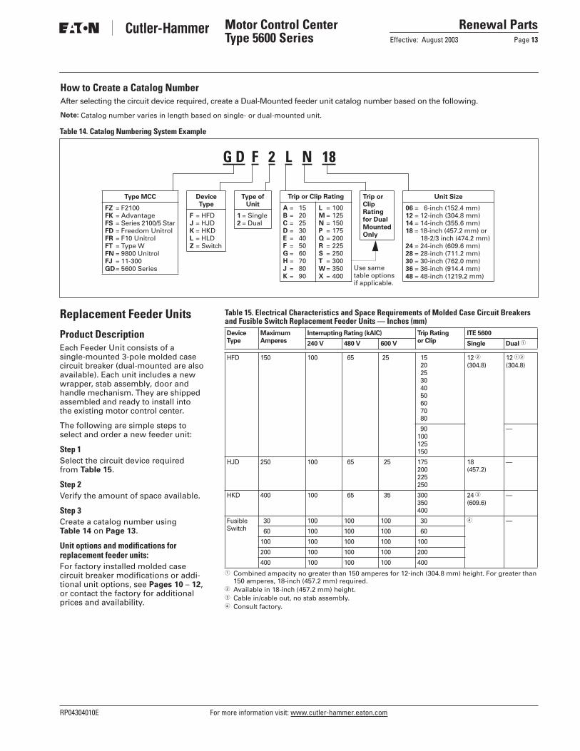
Product DescriptionEach Feeder Unit consists of a single-mounted 3-pole molded case circuit breaker (dual-mounted are also available). Each unit includes a new wrapper, stab assembly, door and handle mechanism. They are shipped assembled and ready to install into the existing motor control center.
The following are simple steps to select and order a new feeder unit:
Step 1Select the circuit device required from Table 15.
Step 2Verify the amount of space available.
Step 3Create a catalog number usingTable 14 on Page 13.
Unit options and modifications for replacement feeder units:For factory installed molded case circuit breaker modifications or addi-tional unit options, see Pages 10 – 12, or contact the factory for additional prices and availability.
How to Create a Catalog NumberAfter selecting the circuit device required, create a Dual-Mounted feeder unit catalog number based on the following.
Note: Catalog number varies in length based on single- or dual-mounted unit.
G D F 2 L N 18
Type MCC
FZ = F2100FK = AdvantageFS = Series 2100/5 StarFD = Freedom UnitrolFR = F10 UnitrolFT = Type WFN = 9800 UnitrolFJ = 11-300GD= 5600 Series
DeviceType
F = HFDJ = HJDK = HKDL = HLDZ = Switch
Type ofUnit
1 = Single2 = Dual
Trip or Clip Rating
A = 15B = 20C = 25D = 30E = 40F = 50G = 60H = 70J = 80K = 90
L = 100M = 125N = 150P = 175Q = 200R = 225S = 250T = 300W = 350X = 400
Trip or ClipRating for DualMounted Only
Unit Size
06 = 6-inch (152.4 mm)12 = 12-inch (304.8 mm)14 = 14-inch (355.6 mm)18 = 18-inch (457.2 mm) or
18-2/3 inch (474.2 mm)24 = 24-inch (609.6 mm)28 = 28-inch (711.2 mm)30 = 30-inch (762.0 mm)36 = 36-inch (914.4 mm)48 = 48-inch (1219.2 mm)
Use same table options if applicable.
Table 15. Electrical Characteristics and Space Requirements of Molded Case Circuit Breakers and Fusible Switch Replacement Feeder Units — Inches (mm)
1 Combined ampacity no greater than 150 amperes for 12-inch (304.8 mm) height. For greater than 150 amperes, 18-inch (457.2 mm) required.
2 Available in 18-inch (457.2 mm) height.3 Cable in/cable out, no stab assembly.4 Consult factory.
DeviceType
MaximumAmperes
Interrupting Rating (kAIC) Trip Ratingor Clip
ITE 5600
240 V 480 V 600 V Single Dual 1
HFD 150 100 65 25
15 20 25 30 40 50 60 70 80
12 2(304.8)
12 12
(304.8)
90100125150
—
HJD 250 100 65 25 175200225250
18(457.2)
—
HKD 400 100 65 35 300350400
24 3(609.6)
—
FusibleSwitch
30 100 100 100 30 4 —
60 100 100 100 60
100 100 100 100 100
200 100 100 100 200
400 100 100 100 400
For more information visit: www.cutler-hammer.eaton.com RP04304010E
Renewal PartsPage 14 Effective: August 2003
Motor Control Center Type 5600 Series
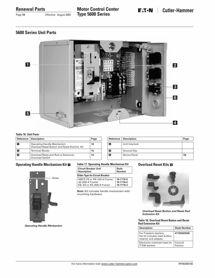
5600 Series Unit Parts
Table 16. Unit Parts
Operating Handle Mechanism Kit 1
Operating Handle Mechanism
Table 17. Operating Handle Mechanism Kit
Note: Kit includes handle mechanism with mounting hardware.
Overload Reset Kits 3
Overload Reset Button and Reset Rod Extension Kit
Table 18. Overload Reset Button and Reset Rod Extension Kit
4
3
21
5
6
Reference Description Page Reference Description Page
1 Operating Handle MechanismOverload Reset Button and Reset Rod Ext. Kit
14 4 Unit Interlock
2 Terminal Blocks 15 5 Ground Clip
3 Overload Reset and Rod or Electronic Overload Switch
14 6 Device Panel 15
Slider
Circuit Breaker UnitDescription
Style Number
Slider Type for Circuit BreakerHMCP, FS or FB (150 A Frame)JD (250 A Frame)KB, KD or KS (400 A Frame)
10-7175-5 10-7176-210-7176-3
Description Style Number
For Freedom starters, the kit includes reset button, retainer and adapter.
4719A92G58
Electronic overload reset for IT-EM starters
ConsultFactory

RP04304010E For more information visit: www.cutler-hammer.eaton.com
Renewal PartsEffective: August 2003 Page 15
Motor Control Center Type 5600 Series
5600 Series Unit Parts
Door Latch Kit
Door Latch Kit
Table 19. Door Latch Kit
Blank Unit Door Kit
Table 20. Blank Unit Door Kit
Divider Pan/Guide Rails with Mounting Hardware
Table 21. Divider Pan/Guide Rails with Mounting Hardware
Device Panel withMounting Hardware 6
Table 22. Device Panel with Mounting Hardware
Unit Support Bracket
Table 23. Unit Support Bracket
Primary/Secondary FuseHolder Kit
Primary/Secondary Fuse Holder Kit
Table 24. Primary/Secondary Fuse Holder Kit
Control Transformers(480/240 V to 120 V Single-Phase)
Table 25. Control Transformers (480/240 V to 120 V Single-Phase)
Terminal Blocks 2
Terminal Blocks
Table 26. Terminal Blocks
NEMA is the registered trademark and service mark of the National Electrical Manufacturers Association. UL is a registered trademark of Underwriters Laboratories Inc. ITE is a federally registered trademark of Integrated Technologies Engineering (ITE). Gould is a federally registered trademark of Gould Electronics Inc. Telemecanique is a federally regis-tered trademark of Schneider Electric SA. Siemens is a federally registered trademark of Siemens AG.
Description StyleNumber
Kit includes two (2) 1/4 turn latches.
ConsultFactory
Dimensions in Inches (mm) StyleNumberHeight Width
Standard Width 6 (152.4)12 (304.8)18 (457.2)24 (609.6)
14-3/4 (374.7)14-3/4 (374.7)14-3/4 (374.7)14-3/4 (374.7)
ConsultFactory
Description Style Number
Divider pan/guide rails with mounting hardware.
ConsultFactory
Description Style Number
Device panel/pivot tube with mounting hardware.
ConsultFactory
Description Style Number
Left-hand sideRight-hand with wirewayRight-hand without wireway
ConsultFactory
Description Style Number
Kit includes fuse block, mounting bracket and screws.
4719A92G59
Description Style Number
50 VA100 VA150 VA200 VA
4719A92G464719A92G484719A92G494719A92G50
250 VA300 VA350 VA500 VA
4719A92G514719A92G524719A92G534719A92G54
Description Style Number
White, 7 circuit, pull-apart 4719A92G57

Renewal PartsPage 16 Effective: August 2003
Motor Control Center Type 5600 Series
© 2003 Eaton CorporationAll Rights ReservedPrinted in USAPublication No. RP04304010EAugust 2003
Eaton CorporationCutler-Hammer business unit1000 Cherrington ParkwayMoon Township, PA 15108-4312USAtel: 1-800-525-2000www.cutler-hammer.eaton.com