USART-Universal Synchronous A Synchronous Receiver Transmitter

Brush-TypeSynchronousMotor ControllerBulletin 1912B, 36-inch, 400ASingle Phase Exciter
User Manual

Important User Information
Read this document and the documents listed in the Additional Resources section about installation, configuration, and operation of this equipment before you install, configure, operate, or maintain this product. Users are required to familiarize themselves with installation and wiring instructions in addition to requirements of all applicable codes, laws, and standards.
Activities including installation, adjustments, putting into service, use, assembly, disassembly, and maintenance are required to be carried out by suitably trained personnel in accordance with applicable code of practice.
If this equipment is used in a manner not specified by the manufacturer, the protection provided by the equipment may be impaired.
In no event will Rockwell Automation, Inc. be responsible or liable for indirect or consequential damages resulting from the use or application of this equipment.
The examples and diagrams in this manual are included solely for illustrative purposes. Because of the many variables and requirements associated with any particular installation, Rockwell Automation, Inc. cannot assume responsibility or liability for actual use based on the examples and diagrams.
No patent liability is assumed by Rockwell Automation, Inc. with respect to use of information, circuits, equipment, or software described in this manual.
Reproduction of the contents of this manual, in whole or in part, without written permission of Rockwell Automation, Inc., is prohibited.
Throughout this manual, when necessary, we use notes to make you aware of safety considerations.
Labels may also be on or inside the equipment to provide specific precautions.
Allen-Bradley, Rockwell Software, Rockwell Automation, and TechConnect are trademarks of Rockwell Automation, Inc.
Trademarks not belonging to Rockwell Automation are property of their respective companies.
WARNING: Identifies information about practices or circumstances that can cause an explosion in a hazardous environment, which may lead to personal injury or death, property damage, or economic loss.
ATTENTION: Identifies information about practices or circumstances that can lead to personal injury or death, property damage, or economic loss. Attentions help you identify a hazard, avoid a hazard, and recognize the consequence.
IMPORTANT Identifies information that is critical for successful application and understanding of the product.
SHOCK HAZARD: Labels may be on or inside the equipment, for example, a drive or motor, to alert people that dangerous voltage may be present.
BURN HAZARD: Labels may be on or inside the equipment, for example, a drive or motor, to alert people that surfaces may reach dangerous temperatures.
ARC FLASH HAZARD: Labels may be on or inside the equipment, for example, a motor control center, to alert people to potential Arc Flash. Arc Flash will cause severe injury or death. Wear proper Personal Protective Equipment (PPE). Follow ALL Regulatory requirements for safe work practices and for Personal Protective Equipment (PPE).

Table of Contents
Chapter 1 Product Overview Required Reference Manuals ............................................................ 1-1Component Layout ............................................................................. 1-2
Chapter 2 Installation Power Connections ............................................................................ 2-1Incoming Line Power .................................................................. 2-1Load Cables and Field Connections ............................................. 2-1For Top Entry Field Cables and Top Exit Load Cables ............... 2-1For Bottom Entry Field Cables and Bottom Exit Load Cables .... 2-4
Control Connections ........................................................................... 2-5
Chapter 3 Commissioning Pre-energization Checks .................................................................... 3-1Motor Information Sheet .................................................................... 3-3SyncPro .............................................................................................. 3-4Programming the SyncPro ................................................................. 3-4Tap Settings for RF1 and RF2 .............................................................. 3-5Measuring the Induced Current ......................................................... 3-5Determining the Tap Settings ............................................................. 3-9Multilin SPM ..................................................................................... 3-10Programming the GE Multilin SPM .................................................. 3-10Applying Medium Voltage ................................................................ 3-11
Chapter 4 Troubleshooting Troubleshooting ................................................................................... 4-1
Chapter 5 Maintenance Removal of Rectifier Bridge Assembly .............................................. 5-1Snubber/Field Switch Board Replacement ......................................... 5-3Firing Board Replacement .................................................................. 5-4SCR Replacement .............................................................................. 5-6Fan Removal and Replacement ......................................................... 5-8Field Discharge Resistor Wiring Check ............................................. 5-9Firing Board Check .......................................................................... 5-10Field Current Maximum Setting Adjustment .................................... 5-12
Chapter 6 Spare Parts Spare Parts Table ............................................................................... 6-1
Appendix A Typical Electrical Diagrams .............................................................. A-1
1912B-UM050B-EN-P – June 2013

ii Table of Contents
1912B-UM050B-EN-P – June 2013

Product Overview
Required Reference Manuals This manual applies to the Bulletin 1912B synchronous starter in a 36-inchwide cabinet and a static exciter rated up to 13 kW. It is intended to provideinformation for installation and commissioning of the synchronous starter,maintenance for the field switch assembly and troubleshooting procedures.The publications listed below are required for detailed information on thosecomponents and procedures that are not covered in this manual. Do notbegin commissioning, installation or maintenance unless the followingpublications are available and understood:
• User Manual, Medium Voltage Controller, Bulletin 1512, 400A,Two-high Cabinet, Publication 1500-UM055B-EN-P
• User Manual, Medium Voltage Contactor, Bulletin 1502, 400A,2400-7200 volts, Publication 1502-UM052B-EN-P
Additional publications, depending on the controller used:
• Instruction Manual, SyncPro™, Bulletin 1901,Publication 1901-UM020B-EN-P
• Other third party products
Chapter 1

1-2 Product Overview
Component Layout
Isolation Switch
Contactor
Scaling Resistors(SyncPro only)
Discharge Resistor
Rectifier Transformer
Field Terminal Cover
Rectifier TransformerFuses (MV)
Isolation Switch
Contactor
Scaling Resistors(SyncPro only)
Discharge Resistor
Rectifier Transformer
Field Terminal Cover
Rectifier TransformerFuses (MV)
Figure 1.1 – Synchrounous Starter Component Layout

Product Overview 1-3
Rectifier Bridge Assembly
Phase Angle Transducer
FSR and ESR Relays
Rockwell Automation SyncPro™
DC Current Transducer (LEM)Power Supply/Current Regulator
DC Current Transducer (LEM)Rectifier Bridge Assembly
Phase Angle Transducer
FSR and ESR Relays
Rockwell Automation SyncPro™
DC Current Transducer (LEM)Power Supply/Current Regulator
DC Current Transducer (LEM)
Figure 1.2 – Low Voltage Component Layout (with Sync Pro™)

1-4 Product Overview
Component Layout (Cont.)
DC Current Transducer (LEM)
Calibration Module *
Rectifier Bridge Assembly
DC Current Transformer *
Power Supply/Current Regulator
Terminal Blocks(Located beneath
Rectifier Bridge Assembly)
* (used only with GE Multilin SPM)
DC Current Transducer (LEM)
Calibration Module *
Rectifier Bridge Assembly
DC Current Transformer *
Power Supply/Current Regulator
Terminal Blocks(Located beneath
Rectifier Bridge Assembly)
* (used only with GE Multilin SPM)
Figure 1.3 – Low Voltage Compartment Layout (with Multilin SPM)

Chapter 2
Installation
Power Connections Incoming Line Power
Refer to User Manual, Medium Voltage Controller, Bulletin 1512, 400A,Two-high Cabinet, Publication 1500-UM055B-EN-P for the procedure toconnect incoming line power to the main bus of the Synchronous starter.
Load Cables and Field Connections
To avoid shock hazards, lock out incoming power (seePower Lock-out Procedure in User Manual, MediumVoltage Controller, Bulletin 1512, Publication 1500-UM055B-EN-P) before working on the equipment.Verify with a hot stick or appropriate voltage measuringdevice that all circuits are voltage free. Failure to do somay result in severe burns, injury or death.
a) Complete the Power-lock out procedure for the medium voltage powercell and the main power bus (see Publication 1500-UM055B-EN-P).
b) Remove the hinge pins from the medium voltage doors and remove thedoors.
c) Open the low voltage power cell doors.
For Top Entry Field Cables and Top Exit Load Cables
1) Disconnect the control wiring harness from the wire plug at the lowerleft side of the contactor (see Figure 2.1).
2) Remove the two self-tapping screws from the upper and lower centervertical channels.
3) Pull on the center vertical channel to swing out the low voltage panel.Open both low voltage panels.
Several wire bundles are routed around the low voltagepanels. Excercise caution when swinging the panelsopen to avoid damaging the wires.
4) Remove the glass-polyester barrier located in front of the currenttransformers.
5) Remove the cable duct barrier and the field terminal cover from thelower power cell (see Figure 2.2).
A T T E N T I O NA T T E N T I O N
A T T E N T I O NA T T E N T I O N

2-2 Installation
Power Connections (cont.)
Remove self-tapping screws fromtop center vertical channel and
swing out low voltage panel.
Remove self-tapping screws frombottom center vertical channel and
swing out low voltage panel.
Remove glass-polyesterbarrier
Disconnect control wiring harnessfrom contactor plug
Figure 2.1 – Access to Cable Terminals (Low voltage panels not shown)
Cable Duct Barrier
Field Cable Terminal Cover
Field Cable Terminal Block
Figure 2.2 – Access to Field Cable Terminal Block(Cutaway view - Power cell doors and side panel not shown)

1
Installation 2-3
For Top Entry Field Cables and Top Exit Load Cables (cont.)
6) Use conduit cover ‘D’ (shown in Figure 2.3) for field (DC) cable entry.
A
B
C
D
Front
Figure 2.3 – Incoming Field Cable Conduit Cover (Top of cabinet shown)
7) Route the field cable (DC) into the cabinet through conduit D. Routethe cables behind the current transformer mounting plate and into thelower power cell. You will need approximately 3 meters (10 feet) ofcable.
8) Pull the cables into the lower power cell and route them behind themounting plate to the floor of the cabinet. (See Figure 2.2)
9) Connect the cables to the field cable terminal block on the floor of thecabinet (see Figure 2.2). Connect the positive power cable to terminalF1 of the field cable terminal block. Connect the negative power cableto terminal F2. Torque the screws to 35-50 lb-in.(4.0-5.6 Nm).
10) Use conduit cover B (see Figure 2.3) for the load cables (AC).
11) Pull the load cables into the cabinet. You will need approximately 1.5meters (5 feet) of cable.
12) Place lugs on cables and connect to the current transformers.Tighten the connections to 48 ft·lb (65 Nm).
13) Connect the cable shields to the ground lug.
14) Reassemble the cabinet. Re-install all barriers removed in previoussteps.
Ensure that all barriers are replaced before energizingthe equipment. Failure to do so may result in electricalfaults and cause damage to the equipment or seriousinjury to personnel.
A T T E N T I O NA T T E N T I O N

2-4 Installation
Power Connections (cont.) For Bottom Entry Field Cables and Bottom Exit Load Cables
1) Remove the two self-tapping screws from the bottom center verticalchannel (see Figure 2.1).
2) Pull on the center vertical channel to swing out the bottom low voltagepanel.
3) Remove the cable duct barrier and the field cable terminal cover fromthe lower power cell (see Figure 2.2).
Several wire bundles are routed around the low voltagepanels. Excercise caution when swinging the panelsopen to avoid damaging the wires.
4) Use conduit cover ‘D’ (shown in Figure 2.4) for field (DC) cable entry.
A
B
D
C
Front
Figure 2.4 – Conduit Covers (Bottom of Cabinet Shown)
5) Route the field cables (DC) into the right of the cabinet. You will needapproximately 1 meter (3 feet) of cable.
6) Connect the cables to the field cable terminal block on the floor of thecabinet (see Figure 2.2). Connect the positive power cable to terminalF1 of the terminal block on the floor of the cabinet. Connect thenegative power cable to terminal F2. Torque the screws to 35-50 lb-in.(4.0-5.6 Nm).
7) Use conduit cover B (see Figure 2.4) for the load cables (AC).
8) Pull the load cables into the cabinet.
9) Route the cable behind the panel to the left of the discharge resistorand connect the cables to the current transformer. Tighten the connec-tions to 48 ft·lb (65 Nm).
A T T E N T I O NA T T E N T I O N
1
Installation 2-5
10) Connect the cable shields to the ground lug.
11) Reassemble the cabinet. Re-install all barriers removed in the previoussteps.
Ensure that all barriers are replaced before energizingthe equipment. Failure to do so may result in electricalfaults and cause damage to the equipment or seriousinjury to personnel.
Control Connections Refer to the wiring diagrams provided with your order and complete theconnection of any remotely located control devices indicated. The TypicalWiring Diagrams (Appendix A) can be used as an additional reference forthose orders using a SyncPro controller.
A T T E N T I O NA T T E N T I O N

1
2-6 Installation

Chapter 3
1912B-UM050B-EN-P – June 2013
Commissioning
Pre-energization Checks A T T E N T I O NA T T E N T I O N
To avoid shock hazards, lock out incoming power (see Power Lock-out Procedure in User Manual, Medium Voltage Controller, Bulletin 1512, Publication 1500-UM055B-EN-P) before working on the equipment. Verify with a hot stick or appropriate voltage measuring device that all circuits are voltage free. Failure to do so may result in severe burns, injury or death.
Verify that: 1) All mechanical interlocks are functioning properly. The medium
voltage doors must not open when the isolation switch handle is in the ON position.
2) All protective barriers are in place and correctly fastened.
3) All fuses are correct class, type and rating.
4) The interior of the cabinet is free from dirt, loose hardware, tools or metal chips. Vacuum clean if necessary.
5) The control plug is securely connected to contactor plug.
6) All power cables are firmly secured and connections are torqued to proper specifications. (Refer to Table 3.A)
7) Any remote wiring to starter is properly connected and torqued to the recommended specifications.
8) The starter is properly grounded to the system ground grid.
9) Where a starter is joined to other enclosures, all ground splices and power bus splices are properly connected (see the section covering Bus Splicing in User Manual, Medium Voltage Controller, Bulletin 1512,Publication 1500-UM055B-EN-P).
Table 3.A – Recommended Torque Hardware Recommended Torque
1/4 in. 6 ft lb (8 N m) 5/16 in. 11 ft lb (15 N m) 3/8 in. 20 ft lb (27 N m) 1/2 in. 48 ft lb (65 N m)
Wire terminal screws 2.0 – 3.3 in lb (2.5 – 4.0 N m)

3-2 Commis sioning
1912B-UM050B-EN-P – June 2013
10) With the motor stopped, measure the DC field windings resistance
directly at the slip rings of the motor or at the field wiring entering the synchronous starter. Ensure that there are no parallel resistances when taking the measurement. Isolate the brushes on the slip ring as they add additional resistance. Direct measurement at the slip rings is the preferred method.
11) Record the measurement from the previous step Rfield= _______ Ω.
12) Compare the resistance from the previous step to the value recorded in the motor Information Sheet, Table 3.B. Any discrepancies must be within tolerable limits (refer to motor manufacturer’s data sheets).
13) All plug-in connectors on the static exciter are firmly secured.
14) Measure the discharge resistance in the starter. Ensure that no parallel resistances are present by disconnecting the appropriate wiring. Check that this value is the same as the motor manufacturer’s specifications or is the same value as the previous starter (for retrofit applications). Ensure that all wires are reconnected.
A T T E N T I O NA T T E N T I O N
Confirm that there is continuity through the discharge resistor and that the discharge resistor is the correct value, especially with retrofit applications. Severe damage to the motor and /or controller may occur if the wrong discharge resistor is selected.
15) If the starter has a SyncPro module installed, proceed to the section titled Programming the SyncPro.
16) If the starter has a Multilin SPM module installed, then proceed to the section titled Programming the Multilin SPM.
Pre-energization Checks (cont.)

Commissioning 3-3
1912B-UM050B-EN-P – June 2013
Motor Information Table 3.B – Motor Information Sheet
CUSTOMER INFORMATION Customer Location Application RA/AB Job Number (Series Number) Customer Starter Tag/ID Name Commissioned By Commissioned Date
SYNCHRONOUS MOTOR NAMEPLATE DATA Manufacturer Serial Number Date of Manufacturing Frame Model Type kVA hp/kW RPM Rated Stator Volts Full Load Amps Power Factor Frequency I Field (A DC) Efficiency V Field (V DC) Phases R field ( ) @ °C Insulation Class - Rotor Insulation Class - Rotor Max. Ambient Temp. (°C) Temp. Rise Stator (°C) Temp. Rise Stator (°C) Time Rating Service Factor Enclosure Locked Rotor kVA/hp
Acceleration Time to Full Speed (asynchronous speed) Time allowed at: 0% speed: _________ s 50% speed: _________ s 95% speed: _________ s
Allowable starts per hour Hot ________ Cold ________ STATIC EXCITER DATA
Voltage DC rating I DC rating DC CT _______ A @ _______ mV
FIELD WINDING INDUCED CURRENT DATA Induced Amps rms at 0% rpm
Induced Amps rms at 50% rpm
Induced Amps at 95% rmp
FIELD DISCHARGE RESISTOR Discharge Resistor ( ___ ) ________ at ________°C Other information (load type, how load is applied (during acceleration/after acceleration/manual/automatic), new or existing motor, retrofit or new starter installation …):

3-4 Commis sioning
1912B-UM050B-EN-P – June 2013
SyncPro Refer to Instruction Manual, SyncPro Bulletin 1901, Publication 1901-UM020B-EN-P, Chapter 4 for the SyncPro setup and commissioning procedures.
Programming the SyncPro The SyncPro must be programmed prior to use to ensure
synchronization and protection of the synchronous motor. Refer to Instruction Manual, SyncPro Bulletin 1901, Publication
1901-UM020B-EN-P, Chapter 5 for the complete procedure to enter the setpoints into the control module.
The following is a brief summary outlining the procedure to enter
the setpoints. Use the data table access module (DTAM) to enter the setpoints
into the SyncPro. Place the DTAM into the MODIFY mode by using jumpers at terminals 1 and 2 through the access port at the rear of the DTAM. Once all the setpoints are entered into the control module, record the data in Table 3.C.
Table 3.C – Setpoints Firmware Revision Level:
Setpoints 1. Minimum percent Synchronous Slip Frequency 2. Power Factor Trip (lagging PF) 3. Power Factor Trip Time Delay 4. Squirrel Cage Protection Trip Time at 95% Speed 5. Squirrel Cage Protection Trip Time at 50% Speed 6. Squirrel Cage Protection Trip Time at 0% Speed (stall) 7. Function Number 8. Incomplete Sequence Trip Time Delay 9. Diagnostic Fault Mask 10. System Frequency (N23:1)
Notes:
• The information from Table 3.B can be used to determine setpoints 4, 5, 6 and 8.
• Setpoints 4, 5 and 6 are used to protect the squirrel cage winding of the motor during starting. The motor manufacturer must specify the maximum allowed time at 95%, 50% and 0% speed. Setpoints 4, 5 and 6 should be set to a value lower than the manufacturer specified allowed time to protect the squirrel cage winding.
• Setpoint 8 is the maximum allowable time for synchronization before the controller aborts the starting sequence. This parameter should be set higher than the normal acceleration time of the motor recorded on the Table 3.B.

Commissioning 3-5
1912B-UM050B-EN-P – June 2013
Scaling resistors (RF1 and RF2) make safe and sufficient voltage available to the A/D pulse generator board for proper determination of the rotor speed. If the settings for RF1 and RF2 are too low, the voltage that appears at the terminals for the A/D pulse generator board may be high enough to damage the board.
If the settings for RF1 and RF2 are too high, the voltage that appears at
the terminals of the A/D pulse generator board may be prematurely blocked and falsely indicate an up-to-speed condition.
1) Determine the following information before proceeding • Induced current at 0% speed - I0 (amps rms); • Induced current at 95% speed - I95 (amps rms); • Resistance of discharge resistor - RDIS (Ω).
2) If I0 and I95 are known, proceed to Determining the Tap Settings, page 3-9.
3) If I0 and I95 are not known, proceed to Measuring the Induced Current.
For the complete procedure refer to Instruction Manual, SyncPro,
Bulletin 1901, Publication 1901-UM020B-EN-P, Chapter 4 – RF1 and RF2 Resistor Setup.
Measuring the Induced Current
A T T E N T I O NA T T E N T I O N
To avoid shock hazards, lock out incoming power (see Power Lock-out procedure in User Manual, Medium Voltage Controller, Bulletin 1512, Publication 1500-UM055B-EN-P) before working on the equipment. Verify with a hot stick or appropriate voltage measuring device that all circuits are voltage free. Failure to do so may result in severe burns, injury or death.
1) Disconnect all connections on the discharge resistors from the
circuit. 2) Jumper across the trip output on the SyncPro (0:3/01) or GE
Multilin SPM.
A T T E N T I O NA T T E N T I O N
The protection features of the SyncPro will not function while the jumper wire is across trip output 0:3/01. Be prepared to stop the motor using the emergency stop if necessary. Failure to do so may result in personal injury and/or damage to the equipment.
Tap Settings for RF1 and RF2

3-6 Commis sioning
1912B-UM050B-EN-P – June 2013
3) Using a resistance measuring device accurate to at least one
decimal place, measure the resistance of point R1 and R3 to obtain a resistance of 1Ω (refer to Figure 3.1). Ensure that there are no parallel resistances while taking this measurement.
Important: The 1Ω value was chosen to provide sufficient
reduction of the total voltage that will appear across the discharge resistor using the voltage divider rule. If the discharge resistor has a value of 2 Ω, the tap selection of 1Ω may not be low enough to provide the necessary reduction in voltage. Select a more suitable tap selection such as 0.2 Ω. Use care in selecting the taps since the strip chart recorder or oscilloscope ratings must not be exceeded.
FROM STATIC EXCITER
( – )( + )100
Strip Chart Recorder
Discharge ResistorR2R1
( – )F2
T1
F1
T3T2
( + )
Field SwitchR2
Field SwitchFiring Circuit
Synchronous Motor
104
FROM STATIC EXCITER
( – )( + )100
Strip Chart Recorder
Discharge ResistorR2R1
( – )F2
T1
F1
T3T2
( + )
Field SwitchR2
Field SwitchFiring Circuit
Synchronous Motor
104
Figure 3.1 – Final Connections to Discharge Resistor
4) Reconnect all wires removed (in Step #1) from the discharge resistor to the circuit.
5) Verify that all wiring is correct. 6) Connect a strip chart recorder or oscilloscopes to point R1 and
R3. The recorder must be peak-to-peak indicating at frequencies of 1 Hz to 60 Hz and be able to read 1000 V AC.
7) Start the motor as during normal operation (i.e. full voltage starting, reduced voltage starting, etc.). See Applying Medium Voltage, page 3-11.
Measuring the Induced Current (cont.)
Commissioning 3-7
1912B-UM050B-EN-P – June 2013
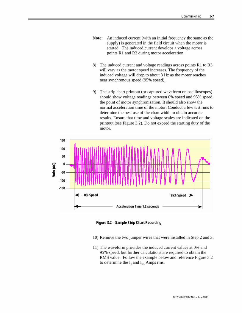
Note: An induced current (with an initial frequency the same as the
supply) is generated in the field circuit when the motor is started. The induced current develops a voltage across points R1 and R3 during motor acceleration.
8) The induced current and voltage readings across points R1 to R3
will vary as the motor speed increases. The frequency of the induced voltage will drop to about 3 Hz as the motor reaches near synchronous speed (95% speed).
9) The strip chart printout (or captured waveform on oscilloscopes) should show voltage readings between 0% speed and 95% speed, the point of motor synchronization. It should also show the normal acceleration time of the motor. Conduct a few test runs to determine the best use of the chart width to obtain accurate results. Ensure that time and voltage scales are indicated on the printout (see Figure 3.2). Do not exceed the starting duty of the motor.
Volts
(AC)
Volts
(AC)
Figure 3.2 – Sample Strip Chart Recording
10) Remove the two jumper wires that were installed in Step 2 and 3. 11) The waveform provides the induced current values at 0% and
95% speed, but further calculations are required to obtain the RMS value. Follow the example below and reference Figure 3.2 to determine the I0 and I95 Amps rms.

3-8 Commis sioning
1912B-UM050B-EN-P – June 2013
EXAMPLE: (Refer to Figure 3.2)
VRMS = Vpk-pk
22 V0pk-pk – the peak-to-peak voltage at 0% speed is approximately 240V
V95pk-pk – the peak-to-peak voltage at 95% speed is approximately 190V
V0 – the rms voltage at 0% speed is V0pk-pk ÷ 22
= 240V ÷ 22 = 84.9 Vrms
V95 – the rms voltage at 95% speed is V95pk-pk ÷ 22
= 190V ÷ 22 = 67.2 VRMS Since the voltage was captured across a 1 Ω resistance, then according to
Ohm’s law the voltage waveform equals the current waveform. I0 = VRMS
RR1-R3 RR1-R3 = 1 Ω in this example Therefore, I0 = 84.9 A rms, and I95 = 67.2 A rms. For your specific set up, determine I0 and I95 then proceed to determining
the Tap Settings, page 3-9.

Commissioning 3-9
1912B-UM050B-EN-P – June 2013
Determining the Tap Settings 1) Use Ohms law to determine the corresponding induced voltages:
a) Voltage Induced @ 0%speed – V0 (V rms) = I0 x RDIS
b) Voltage Induced @ 95%speed – V95 (V rms) = I95 x RDIS 2) The value of V0 and V95 must fall within the lower and upper
limits on the same row of Table 3.D.
Table 3.D – Usable Voltage Range Usable Voltage Range Rfi and Rf2
(kΩ) Lower Limit (V95 rms) Upper Limit (V0 rms) 2.5 60 160 5.0 120 320 7.5 170 480 10.0 230 640 12.5 290 800 15.0 350 950 17.5 400 1100 20.0 460 1300
3) The value of RF1 and RF2 (RF1=RF2) corresponds to the row in
which V0 and V95 were placed. 4) Make the necessary connections on both RF1 and RF2 in the
starter to achieve the resistance as determined from the previous steps. Refer to Instruction Manual, SyncPro Bulletin 1901, Publication 1901-UM020C-EN-P, Chapter 4.
EXAMPLE: Given: I0 = 30A, I95 = 18A, RDIS = 20 Ω
Then V0 = 600V rms and V95 = 360V rms The table shows that a lower limit of 230V and upper limit of 640V
is the most appropriate selection. Thus, RF1 and RF2 must be 10 kΩ each. The value of 10 kΩ is the resistance between the tap setting on the resistor and the A/D Pulse Converter board.
If the value of V0 and/or V95 do not fall within the specified range
shown in Table 3.D, please contact Rockwell Automation Medium Voltage Product Support Division for further assistance.

3-10 Commis sioning
1912B-UM050B-EN-P – June 2013
Multilin SPM Refer to Multilin SPM Instruction Manual for the setup and
commissioning procedures for the Multilin SPM. The SPM must be programmed before use to ensure
synchronization and protection of the synchronous motor. Refer to GE Multilin SPM Instruction Manual for the procedure to enter the setpoints into the control module. Complete Table 3.E once the setpoints are entered.
Table 3.E – SPM Setpoints Configuration Settings
Motor Type (Brush or Brushless) Line Freq (Hz) PF Voltage Reference Statistics Protection Password Calibration FS EXC VOLT FS EXC AMPS FS MTR AMPS Function Motor Power Factor Trip (lag) Power Factor Trip Delay (seconds) Power Factor Suppression % of full load amps Power Factor Mode FAR Delay (seconds) — (Brushless motors only) FCX Delay (seconds) AC CT Rating /5 Full Load Amps (amperes) Locked Rotor Amps (amperes) Sync. Slip % Stall Time (seconds) Run Time x ST DC CT Primary (amperes) High (Exciter) Field Ohms (ohms) (Exciter) Field Amps (amperes) (Exciter) Field Volts (volts) Incomplete Sequence Delay (seconds) Regulator Power Factor Option Power Factor Regulator Gain Option X Regulator Stability Option cycles Regulator Output Option volts Floor Volts Option volts
Programming the GE Multilin SPM

Commissioning 3-11
1912B-UM050B-EN-P – June 2013
1) Ensure that the Pre-energization Check (see page 3-1) have been
completed.
2) Verify that all tools, loose hardware and debris is removed from the interior of the starter.
3) Make a final check of all medium voltage sections in the starter for any damage that may have occurred during installation.
4) Recheck the field discharge resistor to ensure that it is connected in the field discharge circuit (see Field Discharge Resistor Wiring Check, page 5-9).
5) Close all doors and tighten the door locking bolts. The application of medium voltage is now possible.
A T T E N T I O NA T T E N T I O N
If the unit is equipped with a Multilin SPM, do not touch any connection points at the rear of the SPM. Potentials of up to 1000 volts may be present across the inputs VF+ and VF-. Failure to avoid touching the connections may result in injury or death.
6) Check for correct rotation of the motor. Momentarily give the controller a start command, once rotation of the motor is positively noted, remove the start command and/or issue a stop command.
7) If the rotation is not correct switch the two motor cables at the motor terminals.
Important: The phase rotation of the incoming power is important for accurate power factor measurements. Reversing two incoming power connections may result in nuisance tripping and/or no protection against loss of synchronization. The phase sense on the phase angle transducer board must be voltage Va-b and current Ic. Important: At this point in the procedure, the motor can operate under normal load conditions. If possible, avoid running the motor at no load and unity power factor. This causes large oscillations in power factor as the regulator attempts to maintain the unity power factor setting. This is an inherent behaviour of synchronous motors.
8) Monitor the power factor when the motor is started and is
accelerating. The power factor must be lagging during the acceleration stage. If the power factor is not lagging, check the connections from the CT and PT secondary to the SPM. Verify the phase rotation of the medium voltage power supply.

3-12 Commis sioning
1912B-UM050B-EN-P – June 2013
9) While running at a leading power factor and at a constant load,
verify that as DC field current is increased the stator current also increases, and the motor power factor becomes more leading.
10) While running at a leading power factor and at a constant load,
verify that as DC field current is decreased the stator current decreases and the motor power factor becomes more lagging.
11) To verify the power factor reading the following options can be used:
a) If it is possible to run the motor at rated load and rated DC field excitation current, the displayed power factor should be the rated power factor of the motor.
b) Compare the power factor displayed on the DTAM to any of the other power factor measurement devices in the motor circuit.
c) If an oscilloscope is available that can measure current (clamp-on probe), use the first channel to measure line voltage Va-b, and the other channel to measure current in phase A. Phase A current is available from the current transformer in phase A, where the secondary is brought to the low voltage panel.
12) Confirm that the power factor protection functions at the desired trip setting. This is achieved by running at a constant load and then slowly reducing the DC field excitation until the power factor goes below the PF TRIP LEVEL for the duration entered in the PF TRIP DELAY. When this occurs, the starter must open the main contactor, which removes medium voltage to the motor.
13) Set the maximum DC current that can flow into the DC field windings. For the procedure, refer to page 5-12, Field Current Maximum Settings Adjustment.
Programming the GE Multilin SPM (cont.)

Chapter 4Troubleshooting
Table 4.A – Troubleshooting Problem Cause Diagnosis
Excitation source interrupted
• Check low voltage and medium voltage fuses.
No power to Firing Card • Check firing card for power – indicated by a green LED on card • Verify that control (source) power is on. • Check all connections and fuses.
• To check fuses, disconnect J3 and measure from Pin 1 to Pin 5 with an ohmmeter. The resistance should be less than 500 Ohms.
• If resistance is too high, replace the firing card No power to DC Current Transducer (LEM) Power Supply/Current Regulator
• Check card for power – indicated by a green LED on card. • Verify that control (source) power is on by measuring at TB1- pin 5 and at
TB1-pin 4. (see Figure 4.1) • Verify the correct position of SW1 (Voltage Selector Switch) if so equipped
(see Figure 4.1). • Check Fuse F1
• Remove plug in TB1 • Remove fuse and visually inspect or check with an ohmmeter.
• If LED is still not illuminated, replace power supply current regulator, P/N 80198-200-xx. (See Table 6.A)
No current command
• Check door pot for proper setting – refer to Field Current Maximum Setting Adjustment, page 5-12.
• Check the connection at TB3 on the DC Current Transducer (LEM) Power Supply (see Figure 4.1)
• Check J4 (firing board) for proper connection • Check the voltage at TB3-pin 9 and TB3-pin 10 on the DC Current Transducer
(LEM) Power Supply (see Figure 4.1) • If 5V present but not functioning, perform Firing Board Check (see page 5-10) –
replace components if required
No DC output
Faulty Firing Card or faulty SCRs
• Perform Firing Board Check (see page 5-10) to determine faulty component • Replace faulty Firing Board or SCR
Unable to vary DC output between 0 and 100%
DC Current Transducer not connected or faulty
• Check the panel-mounted meter. If it is functioning, then the DC Current Transducer (LEM) Power Supply/Current Regulator is faulty – replace the component.
• Check connections on the DC Current Transducer (LEM) Power Supply (TB2) and on the DC Current Transducer (LEM) (see Figure 4.1)
• If the panel-mounted meter is not functioning, measure the voltage at TB2-pin 3 with reference to TP1 (see Figure 4.1).
• Check adjustment of R56 – see Field Current Maximum Setting Adjustment (see page 5-12).
• If the voltage is less than 0.25V when the current is flowing and the door pot is set to 100%, then the DC Current Transducer (LEM) is faulty – replace the component, P/N 80026-1230xx. (See Table 6.A)
Maximum current setting not properly adjusted
• Perform Field Current Maximum Setting Adjustment (see page 5-12)
Insufficient current at 100% pot setting
Firing card not properly adjusted
• BIAS(R6) and SPAN(R7) pots should both be set to 100% and Resistor Network 2 (RN2) should be labeled 47k
Bridge Rectifier Stack has overheated
• Note: Manually reset the thermistor (see Figure 5.1) • Verify ambient temperature does not exceed 40°C (104°F) • Check for control power at fan • Verify air movement • Replace the fan if it is not functioning
Rectifier over-temperature trip
Loose connections to snubber field switch board
• Verify proper connection at J7, J8, and J9
1912B-UM050B-EN-P – June 2013

4-2 Troubleshooting
1912B-UM050B-EN-P – June 2013
Troubleshooting (Cont.)
T1
TB2
TB3
TB1
TP2
TP1
TP3
TP4
TP5
SW1(Voltage Selector
Switch)
F1
R56
T1
TB2
TB3
TB1
TP2
TP1
TP3
TP4
TP5
SW1(Voltage Selector
Switch)
F1
R56
Figure 4.1 – LEM Power Supply/Current Regulator

Chapter 5Maintenance
To avoid shock hazards, lock out incoming power (seePower Lock-out Procedure in User Manual, MediumVoltage Controller, Bulletin 1512, Publication 1500-UM055B-EN-P) before working on the equipment.Verify with a hot stick or appropriate voltage measuringdevice that all circuits are voltage free. Failure to do somay result in severe burns, injury or death.
1) Open the main medium voltage isolation switch for the starter.
2) Verify that the control power is off by testing the terminal blocksbeneath the cooling fan (see Figures 1.2 or 1.3) with a hot stick orappropriate voltage measuring device.
3) Verify that the excitation source is off by testing points X1 and X2(see Figure 5.1) with a hotstick or appropriate voltage measuring device.
4) Verify that there is no voltage on the positive and negative terminals ofthe DC bus (see Figure 5.1) with a hot stick or appropriate voltagemeasuring device.
5) Remove the retaining screws from the safety shield and remove thesafety shield.
Plug J4
Plug J5
Plug J3
Plug J1
Plug J2
Remove retaining screwsand remove safety shield
Positive DC Bus Terminal
Negative DC Bus Terminal
SCR X1
SCR X2SCR R2
Thermistor withManual Reset
Heatsink
Cooling Fan
Plug J4
Plug J5
Plug J3
Plug J1
Plug J2
Remove retaining screwsand remove safety shield
Positive DC Bus Terminal
Negative DC Bus Terminal
SCR X1
SCR X2SCR R2
Thermistor withManual Reset
Heatsink
Cooling Fan
Figure 5.1 – Electrical Connections to Rectifier Bridge Assembly
Removal of Rectifier BridgeAssembly
1912B-UM050B-EN-P – June 2013
A T T E N T I O NA T T E N T I O N

5-2 Maintenance
1912B-UM050B-EN-P – June 2013
Removal of Rectifier Bridge 6) Loosen the wire retaining screws from SCRs X1, X2 and R2, andAssembly (cont.) remove the wires. Remove the wires from the terminals on the positive
and negative terminals of the DC bus. Mark the wires as they areremoved to ensure proper reconnection.
7) Remove the wire plugs at points J3, J4, (see Figure 5.1) J9 (see Figure5.3), and at the cooling fan.
Remove self-tapping screws Front ViewRemove self-tapping screws Front View
Figure 5.2 – Removing the Rectifier Bridge Assembly
8) Remove the self-tapping screws that secure the rectifier bridge assem-bly to the mounting plate. Remove the bottom two first, support therectifier bridge assembly while removing the top two (see Figure 5.2)
9) Reverse the procedure to reinstall the rectifier bridge assembly.
10) Torque the wire retaining screws at X1, X2 and R2 to 2.0 – 3.3 in./lbs.(2.5 to 4 N/m).
11) Torque the wire terminal screws at the positive and negative terminalsof the DC bus to 2.0 – 3.3 in./lbs. (2.5 to 4 N/m).
12) If any components were replaced, conduct the appropriate tests toverify proper functioning.
Ensure all barriers are replaced before energizing theequipment. Failure to do so may result in electrical faultsand cause damage to equipment or serious injury topersonnel.
A T T E N T I O NA T T E N T I O N

Maintenance 5-3
1912B-UM050B-EN-P – June 2013
To avoid shock hazards, lock out incoming power (seePower Lock-out Procedure in User Manual, MediumVoltage Controller, Bulletin 1512, Publication 1500-UM055B-EN-P) before working on the equipment.Verify with a hot stick or approppriate voltage measuringdevice that all circuits are voltage free. Failure to do somay result in severe burns, injury or death.
1) Open the main medium voltage isolation switch for the starter.2) Verify that the control power is off by testing the terminal blocks
beneath the cooling fan (see Figures 1.2 or 1.3) with a hot stick orappropriate voltage measuring device.
3) Verify that the excitation source is off by testing points X1 and X2 (seeFigure 5.1) with a hotstick or appropriate voltage measuring device.
4) Verify that there is no voltage on the positive and negative terminals ofthe DC bus (see Figure 5.1) with a hot stick or appropriate voltagemeasuring device.
5) Verify that the part number of the replacement board matches that ofthe existing board.
6) Disconnect the wire plugs from J7, J8 and J9 (see Figure 5.3).7) Remove the four retaining screws.
Plug J8
Plug J7
Plug J9
Remove the retaining screws and
remove the board.
Left Side ViewSnubber/Field Switch Board
Safety Shield
Plug J8
Plug J7
Plug J9
Remove the retaining screws and
remove the board.
Left Side ViewSnubber/Field Switch Board
Safety Shield
Figure 5.3 – Snubber/Field Switch Board Replacement
8) Remove the board.9) Install the new board.10) Install the four retaining screws.11) Reconnect the plugs to J7, J8, and J9.
A T T E N T I O NA T T E N T I O NSnubber/Field SwitchBoard Replacement

5-4 Maintenance
1912B-UM050B-EN-P – June 2013
Firing Board Replacement To avoid shock hazards, lock out incoming power (seePower Lock-out Procedure in User Manual, MediumVoltage Controller, Bulletin 1512, Publication 1500-UM055B-EN-P) before working on the equipment.Verify with a hot stick or appropriate voltage measuringdevice that all circuits are voltage free. Failure to do somay result in severe burns, injury or death.
1) Open the main medium voltage isolation switch for the starter.
2) Verify that the control power is off by testing the terminal blocksbeneath the cooling fan (see Figures 1.2 or 1.3) with a hot stick orappropriate voltage measuring device.
3) Verify that the excitation source is off by testing points X1 and X2 (seeFigure 5.1) with a hotstick or appropriate voltage measuring device.
4) Verify that there is no voltage on the positive and negative terminals ofthe DC bus (see Figure 5.1) with a hot stick or appropriate voltagemeasuring device.
5) Remove the plugs in J1, J2, J3, and J4 (see Figure 5.4).
6) Remove the four retaining screws from the board.
7) Remove the board.
8) Using the existing board as a reference, verify that the 50/60Hz jumper(marked J8) is set correctly on the replacement board. Pins 2 and 3should be connected for 60Hz operations. The jumper should beremoved for 50Hz operation.
9) Use a screwdriver to turn both pots (R6 and R7 on the FCR4100 firingboard) fully clockwise. Seal the pots in the fully clockwise positionwith Loctite adhesive or equivalent.
A T T E N T I O NA T T E N T I O N

Maintenance 5-5
1912B-UM050B-EN-P – June 2013
Turn both pots (R6 and R7)fully clockwise
Verify correct jumper (J8) setting
Plug J2
Plug J1
Plug J3 Plug J4
Plug J5 (Not used)
Safety shield
Right Side View
Pins 3 & 4
J6
Turn both pots (R6 and R7)fully clockwise
Verify correct jumper (J8) setting
Plug J2
Plug J1
Plug J3 Plug J4
Plug J5 (Not used)
Safety shield
Right Side View
Pins 3 & 4
J6
Figure 5.4 – Firing Board Replacement
10) Verify that pins 3 and 4 on J6, located on the card, are jumpered.(Refer to Figure 5.4)
11) Install the new firing board assembly.
12) Reconnect all connectors.
13) Perform the Firing Board Firing Check, page 5-10.
14) Perform the Field Current Maximum Setting Adjustment, page 5-12.

5-6 Maintenance
1912B-UM050B-EN-P – June 2013
SCR Replacement To avoid shock hazards, lock out incoming power (seePower Lock-out Procedure in User Manual, MediumVoltage Controller, Bulletin 1512, Publication 1500-UM055B-EN-P) before working on the equipment.Verify with a hot stick or appropriate voltage measuringdevice that all circuits are voltage free. Failure to do somay result in severe burns, injury or death.
1) Open the main medium voltage isolation switch for the starter.
2) Verify that the control power is off by testing the terminal blocksbeneath the fan (see Figure 1.1 or 1.2) with a hot stick or appropriatevoltage measuring device.
3) Verify that the excitation source is off by testing points X1 and X2 (seeFigure 5.1) with a hotstick or appropriate voltage measuring device.
4) Verify that there is no voltage on the positive and negative terminals ofthe DC bus (see Figure 5.1) with a hot stick or appropriate voltagemeasuring device.
5) Remove the retaining screws from the safety shield and remove thesafety shield.
6) Remove the screws from the DC bus and remove the DC bus bars.
Front View
SCR X1
SCR X2
SCR R2
Remove retaining screws from DC bus and remove bus bars.
Snubber Field Switch Board(Gate connections from SCRsmust face towards this board.)
Gate Connector Plugs
Fan
Air FlowFront View
SCR X1
SCR X2
SCR R2
Remove retaining screws from DC bus and remove bus bars.
Snubber Field Switch Board(Gate connections from SCRsmust face towards this board.)
Gate Connector Plugs
Fan
Air Flow
Figure 5.5 – SCR Replacement
A T T E N T I O NA T T E N T I O N

Maintenance 5-7
1912B-UM050B-EN-P – June 2013
7) Remove the gate connector plug from the SCRs that will be replaced(see Figure 5.5).
8) Remove the retaining screws from the SCR that will be replaced. Markthe wires to ensure proper reconnection.
Replace SCRs X1 and X2 together. The failure of eitherSCR may damage the other. Failure to replace both SCRs(X1 and X2) may result in premature failure of thecomponents. SCR R2 operates independently of theothers and may be replaced separately.
9) Remove the SCR and replace it with the new one. When installing newdevices, start at the top (X1) and work down. (Refer to Figure 5.5)
Important: The SCRs must be positioned with the Gate Connectionslocated toward the snubber/field switch (SFS) board.
10) Reinstall the bus bars. Do not completely tighten the screws.
11) Position the SCR and bus bar assembly on the stack in the sameposition as the original devices.
12) Tighten SCR retaining screws to 2.0 – 3.3 in./lbs. (2.5 to 4 N/m).
13) Tighten bus bar screws to 2.0 – 3.3 in./lbs. (2.5 to 4 N/m).
14) Replace the safety shield.
15) Perform the Firing Board Firing Check Procedure, page 5-10.
A T T E N T I O NA T T E N T I O N

5-8 Maintenance
1912B-UM050B-EN-P – June 2013
To avoid shock hazards, lock out incoming power (seePower Lock-out Procedure in User Manual, MediumVoltage Controller, Bulletin 1512, Publication 1500-UM055B-EN-P) before working on the equipment.Verify with a hot stick or appropriate voltage measuringdevice that all circuits are voltage free. Failure to do somay result in severe burns, injury or death.
1) Open the main medium voltage isolation switch for the starter.
2) Verify that the control power is off by testing the terminal blocksbelow the fan with a hot stick or appropriate voltage measuring device.
3) Verify that the excitation source is off by testing points X1 and X2 (seeFigure 5.1) with a hotstick or appropriate voltage measuring device.
4) Disconnect the fan power plug.
5) Remove the four fan mounting screws and remove the fan. Make noteof air flow direction on fan.
6) Verify that the voltage rating of the new fan matches that of the unit’scontrol voltage.
7) Install the new fan. Check air flow direction on fan.
8) Replace all connections.
9) Apply test power. The fan should function as soon as power is restored.Airflow should be towards the top of the rectifier bridge assembly.Check wiring if the fan does not operate.
A T T E N T I O NA T T E N T I O NFan Removal and Replacement

Maintenance 5-9
1912B-UM050B-EN-P – June 2013
To avoid shock hazards, lock out incoming power (seePower Lock-out Procedure in User Manual, MediumVoltage Controller, Bulletin 1512, Publication 1500-UM055B-EN-P) before working on the equipment.Verify with a hot stick or appropriate voltage measuringdevice that all circuits are voltage free. Failure to do somay result in severe burns, injury or death.
1) Open the main medium voltage isolation switch for the starter.
2) Verify that the control power is off by testing the terminal blocksbelow the fan with a hot stick or appropriate voltage measuring device.
3) Verify that the excitation source is off by testing points X1 and X2 (seeFigure 5.1) with a hotstick or appropriate voltage measuring device.
4) Remove retaining screws from safety shield and remove safety shield(see Figure 5.1).
5) Do a visual check to verify that all field related wiring appears correct.Use the supplied electrical drawings for reference.
6) Record the following information.
• Motor Rotor Resistance
• Installed Field Discharge Resistor Resistance
7) Measure the resistance from the exciter stack’s positive DC bus to thenegative DC bus. The resulting reading should be approximatelyequal to the connected motor’s rotor resistance Refer to the Rfieldmeasurement in Table 3.B.
If the readings are not close, check the wiring at the motor fieldterminals for tightness and proper connection points.
8) Measure the resistance from R2 to the negative DC bus. The readingshould be nearly equal to the sum of the measured rotor resistance andthe measured field discharge resistor resistance.
9) Measure the resistance from the positive DC bus to the negative DCbus (Rotor Resistance). Place a jumper across the negative DC busterminal to the R2 SCR terminal. This will short the SCR and thereading should decrease. Record the resulting reading. The readingshould be equal to the equivalent parallel resistance of the measuredrotor resistance and the measured field discharge resistor resistance.The equivalent resistance can be calculated asER = 1/(1/Rotor Resistance + 1/FDR).
Field Discharge ResistorWiring Check A T T E N T I O NA T T E N T I O N
5-10 Maintenance
1912B-UM050B-EN-P – June 2013
Firing Board Check To avoid shock hazards, lock out incoming power (seePower Lock-out Procedure in User Manual, MediumVoltage Controller, Bulletin 1512, Publication 1500-UM055B-EN-P) before working on the equipment.Verify with a hot stick or appropriate voltage measuringdevice that all circuits are voltage free. Failure to do somay result in severe burns, injury or death.
1) Verify that the control power is off by testing the terminal blocksbeneath the cooling fan (see Figures 1.2 or 1.3) with a hot stick orappropriate voltage measuring device.
2) Verify that the excitation source is off by testing points X1 and X2 (seeFigure 5.1) with a hotstick or appropriate voltage measuring device.
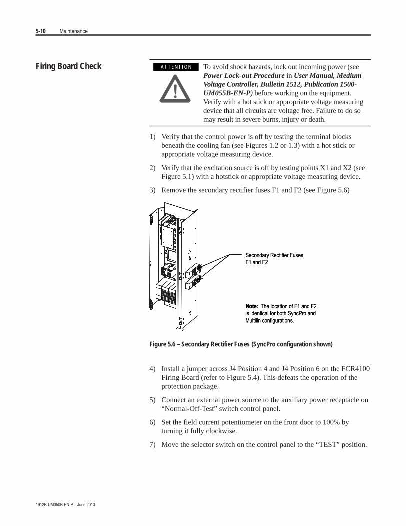
3) Remove the secondary rectifier fuses F1 and F2 (see Figure 5.6)
Secondary Rectifier FusesF1 and F2
Note: The location of F1 and F2is identical for both SyncPro andMultilin configurations.
Secondary Rectifier FusesF1 and F2
Note: The location of F1 and F2is identical for both SyncPro andMultilin configurations.
Figure 5.6 – Secondary Rectifier Fuses (SyncPro configuration shown)
4) Install a jumper across J4 Position 4 and J4 Position 6 on the FCR4100Firing Board (refer to Figure 5.4). This defeats the operation of theprotection package.
5) Connect an external power source to the auxiliary power receptacle on“Normal-Off-Test” switch control panel.
6) Set the field current potentiometer on the front door to 100% byturning it fully clockwise.
7) Move the selector switch on the control panel to the “TEST” position.
A T T E N T I O NA T T E N T I O N

Maintenance 5-11
1912B-UM050B-EN-P – June 2013
8) Use an AC voltmeter to measure the following voltages for each SCR.Do not remove the plug for this procedure. Check the voltages fromthe back of the plug. Pin #1 is marked on the firing card and indicatedon the plug by a small protrusion. Measure the voltage between:• Plug J1, pins 1 and 2• Plug J1, pins 5 and 6• Plug J2, pins 1 and 2• Plug J2, pins 4 and 5(Refer to Figure 5.4)
The measured voltage should be 0.5 Volts +/- 0.25 Volts.
Table 5.A – Troubleshooting Chart Voltage Diagnosis
Less than 0.25 V
• No control power • FSR not bypassed (Step 3) • J1/J2 not installed correctly • Door pot not set to 100% • F aulty firing board • S CR shorted
0.26 – 0.75 V • Normal device and firing circuit
0.76 V and over • I ncorrect gate connections • Gat e open
To verify whether firing board has failed or SCR is shorted, remove the plug from the position where the voltage was measured. Use a voltmeter to measure the voltage at the plug on the board.
• If the voltage is greater than 0.5 V, the corresponding SCR has failed and must be replaced. • If the voltage is less than 0.5 V, replace the firing board.
9) Return the selector switch to the “OFF” position and disconnect theexternal power source. Remove all jumpers.
10) The following steps are optional, but provide an additional check forproper functioning of the firing board.
11) Remove the rectifier transformer secondary fuses (refer to suppliedelectrical drawings for location).
12) Remove the safety shield.
13) Connect a jumper from wire #12 to X1 (refer to electrical drawings inAppendix A for location).
14) Connect a jumper from wire #1 to X2 (refer to electrical drawings inAppendix A for location).
15) Disconnect the motor field connections at the field terminals
16) Connect an appropriate load in place of the motor field. 200-300 wattsof incandescent bulbs make a good load.
17) Connect an external power source to the auxiliary power receptacleon the control panel. Move the selector switch on the control panel tothe TEST position.

5-12 Maintenance
1912B-UM050B-EN-P – June 2013
Firing Board Check (cont.) 18) Adjust the field current POT in the door. There should be somevariation in the the lamp brightness (or voltage across the load) as thePOT is rotated. There will only be minimal control as the load currentis a fraction of the rated load current.
19) Move the selector switch on the control panel to the OFF postitionand disconnect the external power source.
20) Remove the test load.
21) Reconnect the motor field terminals.
22) Remove the jumpers to X1 and X2.
23) Reinstall the safety shield.
24) Reinstall the rectifier transformer secondary fuses.
25) Perform the Field Discharge Resistor Wiring Check, page 5-9.
Hazardous voltages will be present in the low voltagepower cell during this procedure. Use the appropriateprotective equipment and work practices to avoid shockhazard. Failure to do so may result in severe burns,injury or death.
1) Open the low voltage door.
2) Start the motor and allow it to reach synchronous speed.
3) Set the door-mounted field current control to 100%.
4) Adjust the R56 resistor on the LEM power supply board (see Figure4.1) to the desired maximum field current.
Note: The factory setting is approximately 110% of the motor rating.Monitor the field current with the door-mounted field current meter.Turn the resistor clockwise to increase the current and counter-clock-wise to decrease the current.
5) Stop the motor if required.
6) Close the low voltage door.
Field Current Maximum SettingAdjustment A T T E N T I O NA T T E N T I O N

Chapter 6
Spare Parts
Table 6.A – Spare Parts Part Number Description 80026-135-01 SCR pack (dual) used for rectification and field switch 80026-141-01 FCR4100 firing card 80026-142-01 Bridge Rectifier Fan (120V, 50/60 Hz) 80026-142-02 Bridge Rectifier Fan (230V, 50/60 Hz) 80174-902-11 Fuse, 100mA for 120V 80174-902-12 Fuse, 50 mA for 230 V
80190-200-01-R DC Current Transducer (LEM) Power Supply/Current Regulator (120V) 80190-200-02-R DC Current Transducer (LEM) Power Supply/Current Regulator (230V)
80026-285-51 Single phase rectifier bridge assembly with snubber/field switch board (120V, 60 Hz Control) – up to 67 VDC
80026-285-52 Single phase rectifier bridge assembly with snubber/field switch board (120V, 60 Hz Control) – up to 125 VDC
80026-285-53 Single phase rectifier bridge assembly with snubber/field switch board (120V, 60 Hz Control) – up to 250 VDC
80026-285-54 Single phase rectifier bridge assembly with snubber/field switch board (230V, 60 Hz Control) – up to 67 VDC
80026-285-55 Single phase rectifier bridge assembly with snubber/field switch board (230V, 60 Hz Control) – up to 125 VDC
80026-285-56 Single phase rectifier bridge assembly with snubber/field switch board (230V, 60 Hz Control) – up to 250 VDC
80026-285-57 Single phase rectifier bridge assembly with snubber/field switch board (110V, 50 Hz Control) – up to 67 VDC
80026-285-58 Single phase rectifier bridge assembly with snubber/field switch board (110V, 50 Hz Control) – up to 125 VDC
80026-285-59 Single phase rectifier bridge assembly with snubber/field switch board (110V, 50 Hz Control) – up to 250 VDC
80026-285-60 Single phase rectifier bridge assembly with snubber/field switch board (220V, 50 Hz Control) – up to 67 VDC
80026-285-61 Single phase rectifier bridge assembly with snubber/field switch board (220V, 50 Hz Control) – up to 125 VDC
80026-285-62 Single phase rectifier bridge assembly with snubber/field switch board (220V, 50 Hz Control) – up to 250 VDC
For additional synchronous starter spare parts, refer to the followingdocuments:• User Manual, Medium Voltage Controller, Bulletin 1512, 400A,
Two-high Cabinet, Publication 1500-UM055B-EN-P• User Manual, Medium Voltage Contactor, Bulletin 1502, 400A,
2400-7200 Volts, Publication 1502-UM050B-EN-P• Instruction Manual, SyncPro™, Bulletin 1901,
Publication 1901-UM020B-EN-P
1912B-UM050B-EN-P – June 2013

1912B-UM050B-EN-P – June 2013
6-2 Spare Parts

Appendix ATypical Electrical Diagrams
Figure A.1 – Typical Wiring Diagram (Sheet 1)
1

1
A-2 Typical Electrical Diagrams
Figure A.2 – Typical Wiring Diagram (Sheet 2)

1
Typical Electrical Diagrams A-3
Figure A.3 – Typical Wiring Diagram (Sheet 3)

1
A-4 Typical Electrical Diagrams


Medium Voltage Products, 135 Dundas Street, Cambridge, ON, N1R 5X1 Canada, Tel: (1) 519.740.4100, Fax: (1) 519.623.8930, www .ab.com/mvb
Publication 1912B-UM050B-EN-P – June 2013Supersedes Publication 1912-UM050A-EN-P – November 2004 Copyright © 2013 Rockwell Automation. All rights reserved. Printed in Canada.