In-Situ Observation of Crack Behavior in Plasma-Sprayed 7 wt% Yttria-Stabilized Zirconia

www.actamat-journals.com
Acta Materialia 54 (2006) 5195–5207
Morphology and thermal conductivity of yttria-stabilizedzirconia coatings
Hengbei Zhao a,*, Fengling Yu b, Ted D. Bennett b, Haydn N.G. Wadley a
a Materials Science Department, University of Virginia, Charlottesville, VA 22904, USAb Department of Mechanical and Environmental Engineering, University of California, Santa Barbara, CA 93106, USA
Received 14 January 2006; received in revised form 8 June 2006; accepted 9 June 2006Available online 18 September 2006
Abstract
An electron beam directed vapor deposition method was used to grow 7 wt.% Y2O3–ZrO2 (7YSZ) coatings and the effects of substraterotation upon the coating porosity, morphology, texture, and thermal conductivity were explored. As the rotation rate was increased, thetexture changed from Æ111æ to Æ100æ. Under stationary deposition, the coatings were composed of straight columns, while low-frequencyrotation resulted in wavy columns. Increases in rotation rate resulted in a gradual straightening and narrowing of the growth columns.The pore fraction slowly decreased as the rotation rate increased. The thermal conductivity was found to be inversely related to the porefraction. The structural and thermal conductivity alterations are a result of changes to flux shadowing associated with specimen rotationin a gas jet-entrained vapor plume. The minimum thermal conductivity at a low rotation rate is 0.8 W/(m K), well below that of con-ventionally deposited coatings.� 2006 Acta Materialia Inc. Published by Elsevier Ltd. All rights reserved.
Keywords: Thermal barrier coatings; 7YSZ; Pore morphology
1. Introduction
Thermal barrier coating (TBC) systems are widely usedto protect the hot, internally cooled components of gas tur-bine engines by reducing the metal substrate temperaturesand increasing their oxidation and corrosion resistance[1,2]. Current TBC systems consist of two layers. Either aplatinum-modified nickel aluminide (NiAl + Pt) diffusioncoating [3] or an MCrAlY (M refers to one or more ofthe elements Co, Ni, and Fe) [4] overlayer bond coat is usedto provide substrate oxidation/corrosion protection [5]. Aceramic topcoat composed of partially yttria-stabilized zir-conia (YSZ) is then applied to provide thermal insulation[1]. This ceramic layer is currently applied either by elec-tron beam physical vapor deposition (EB-PVD) [6–8] orby air plasma spraying (APS) [9]. In order to avoid high-
1359-6454/$30.00 � 2006 Acta Materialia Inc. Published by Elsevier Ltd. All
doi:10.1016/j.actamat.2006.06.028
* Corresponding author. Tel.: +1 434 982 4783.E-mail address: [email protected] (H. Zhao).
temperature phase transitions, the zirconia is usually stabi-lized with 6–8 wt.% Y2O3 [1].
Fully dense, large grain size YSZ with 6–8 wt.% Y2O3
stabilization has a reported thermal conductivity in therange 2.2–2.9 W/(m K) [10]. It has a high melting point(approximately 2700 �C) [11], a relatively high coefficientof thermal expansion (11.0 · 10�6/K) [12], and is chemi-cally inert in the hydrocarbon combustion atmospheresof gas turbine engines [2]. However, zirconia also has ahigh oxygen ion conductivity at the use temperature ofTBC systems, and this, combined with extensive, intercon-nected networks of pores, results in rapid oxygen migrationthrough the ceramic layer to the bond coat. This results inthe formation of a thermally grown oxide (TGO) layer onthe bond coat surface whose growth rate increases stronglywith temperature [13]. The TGO plays an important role inTBC performance; failure in EB-PVD TBCs is often initi-ated at or near the TGO bond coat/YSZ interface [12].
The thermal conductivity of the ceramic layer has beenfound to depend on the pore morphology within a coating
rights reserved.

5196 H. Zhao et al. / Acta Materialia 54 (2006) 5195–5207
[14]. In APS coatings, inter-splat pores are roughlyaligned parallel to the substrate surface and are accompa-nied by microcracks and a fine grain size [15]. This poreorientation is highly effective at impeding the flow ofthe heat through the coating. APS coatings therefore havelow effective thermal conductivities of 0.8–1.1 W/(m K)[10]. However, this is achieved at the expense of surfacesmoothness, in-plane strain tolerance, and erosion resis-tance [12,15]. These limitations constrain their use tolow thermal cyclic environments [12,16]. Modificationsto the APS deposition conditions have enabled dense, ver-tically cracked (DVC) coatings to be deposited [17]. Anew, potentially lower-cost solution precursor plasmaspray (SPPS) deposition process has also been proposed[18]. It has the potential for creating more durable TBCswith reduced strain compatibility limitations compared toconventional APS TBCs.
EB-PVD coatings consist of collinear elongated single-crystal columns with a predominantly Æ100æ orientation[8,19]. They contain a small volume fraction of intercolum-nar pores which are orientated perpendicular to the coatinginterface [20]. Due to these elongated intercolumnar pores,EB-PVD coatings are more strain tolerant in directionsnormal to the columns (in-plane directions) and they aremore resistant to spallation than APS coatings [15]. A finerdistribution of intracolumn pores is also present within thecolumns [20]. Modeling has shown that these are muchmore effective at impeding heat flow through the coatingas they are generally inclined to the heat flow [20]. Never-theless, EB-PVD coatings have higher thermal conductivi-ties (approximately 1.5–1.9 W/(m K) [10,21]) than theirAPS counterparts. A practical challenge confronting cur-rent EB-PVD ceramic layer growth is to develop processesthat result in a thermal conductivity similar to that of theAPS process while retaining the other beneficial coatingcharacteristics.
Both experimental and recent atomistic modeling stud-ies of vapor deposited coatings indicate that the pore mor-phology can be influenced by process variables which affectthe vapor atoms’ incidence angle and the mobility of con-densed species on the solid–vapor interface. These variablesinclude the substrates temperature [22,23], the depositionrate [22,24], the background gas pressure [22,25,26], thevapor plume composition [27], and the substrates initialroughness [28]. Experimental studies indicate that highlyporous columnar morphologies are associated with lowkinetic energy, oblique vapor incidence angles, low sub-strate temperatures, high deposition rates, rough sub-strates, and high chamber pressures [22,28–30]. Atomisticmodels of coating growth support these observations[31,32] and link pore formation to flux shadowing underconditions of restricted adatom mobility on the coatingsurface.
Access to the conditions that produce optimal porestructures are limited by the design of current EB-PVD sys-tems. Low chamber pressures (<10�4 Pa) are needed tofacilitate electron beam propagation and this results in less
collisional vapor transport to the substrate. This in turnleads to a narrow range of flux incidence angles when thevapor impacts a flat, stationary substrate. Flux shadowingis then promoted by substrate rotation, which broadens theeffective flux incidence angle distribution leading toincreases in porosity [33]. This rotation also has a practicalvalue. It enables the uniform coating of complex shapedcomponents such as the airfoils and guide vanes used ingas turbine engines. Schulz et al. [19] have explored theeffects of rotation on the microstructure and texture of con-ventional EB-PVD coatings. They, and others [8], havefound through pole figure analysis that rotation producesa transition from Æ1 11æ to Æ100æ out-of-plane texture andthe development of an in-plane orientation relationshipbetween the growth columns.
There are many ways in which the incidence angle of acondensing flux (and thus a coating’s pore morphology)can be manipulated. Hass et al. [34] inclined a substratebetween two fixed angles to produce a symmetrical coat-ing with zigzag-shaped columns over the entire thickness.In this structure, the intercolumnar gaps (primary pores)were orientated obliquely to more effectively impede theheat transport across the coating. A second approach isto use high-pressure environments to broaden the inci-dence angle distribution of the flux [35]. In directed vapordeposition (DVD) [3,36], the flux is entrained in a super-sonic gas jet that is directed towards the substrate. Withthe jet present, chamber pressures are much higher andthe mean free path is greatly reduced so that many vaporphase collisions occur. Multiple scattering events duringthe transport of vapor towards the substrate, and espe-cially during its passage above the surface, broaden theangular incidence distribution significantly. It can alsoincrease the frequency of three-body collisions and theprobability of nucleating vapor-phase clusters, which pro-vide a different mechanism of coating morphology manip-ulation. Previous preliminary studies have indicated thatYSZ layers deposited onto stationary substrates havehighly porous, columnar morphologies with hierarchicalpore distributions which could be manipulated by thejet flow conditions [34,35]. By combining the DVDapproach with substrate tilting, Hass et al. created zigzagstructures with through-thickness thermal conductivitiesas low as 0.8 W/(m K) [34].
Here, this EB-DVD process has been used to depositYSZ coatings. The study focuses upon the relationshipbetween pore morphology, thermal conductivity, and sub-strate rotation under high growth pressure conditions. Themorphology, texture, and pore volume fraction of YSZfilms deposited at different rotation rates are systematicallyinvestigated and linked to the thermal conductivity anddensity of the coatings. We show that coatings with a ther-mal conductivity as low as 0.8 W/(m K) can be grownunder low rotation rate, high-pressure growth conditions.Interestingly, we find that this conductivity only risesslightly (to �1 W/(m K)) when much higher rotation ratesare used.

H. Zhao et al. / Acta Materialia 54 (2006) 5195–5207 5197
2. Experimental
2.1. EB-DVD
The EB-DVD system is schematically illustrated inFig. 1. It combines high-rate, low-vacuum electron beamevaporation with a rarefied gas jet to entrain vapor andtransport it to a substrate. The EB-DVD gun system usedhere has a maximum power of 10 kW, a beam acceleratingvoltage of 70 kV to facilitate propagation through a high-pressure deposition chamber, and includes a high-speedelectron beam scanning system that enabled up to100 kHz rastering of a 0.5 mm diameter electron beam overthe source surface. Vacuum chamber pressures between 3.3and 13.3 Pa can be accessed by a multi-pump vacuum sys-tem. The evaporation source was positioned in the throatof a water-cooled copper nozzle and a He/O2 gas jet wasformed in the vicinity of the evaporation surface. Duringoperation, the source material was vaporized and gas jetatom collisions with the vapor plume directed the vaportowards the substrate. Using jet conditions that enable allthe vapor to be entrained in the gas jet flow facilitatesdeposition of a large fraction of the evaporated flux onthe substrate. This results in high materials utilization effi-ciency and concomitantly high deposition rates [37].
Fig. 1. Experimental coating geometry.
The gas jet flow speed and density can be controlled bythe choice of upstream and downstream pressure ratio andthe nozzle dimensions. Hass et al. [36] have shown thatDVD can provide non-line-of-sight deposition on non-pla-nar substrates. The degree of non-line-of-sight depositionand thus the coating thickness uniformity depends on thegas jet flow conditions. The coating thickness uniformitydramatically increased as the pressure ratio Pu/Po
(upstream pressure Pu of a nozzle opening and a lowerdownstream or chamber pressure Po) was decreased. In thispaper, a large pressure ratio condition was used, whichresulted in a more line-of-sight deposition process similarto that of conventional EB-PVD processes. A detaileddescription of the method and analyses of it can be foundin various references [11,36,38].
2.2. TBC deposition
The EB-DVD approach was used to deposit 7YSZ(zirconia stabilized with 7 wt.% yttria) layers on stationaryand rotated substrates as shown in Fig. 1. The disc-shapedsubstrates were mounted on a holder rotating around ahorizontal axis normal to a 1.25 cm diameter source ingot(and vapor plume) axis. The substrates (provided by GEAircraft Engines) were 2.54 cm in diameter and made froma Hastelloy-X alloy. They were coated with a 200 lm thickNi0.475Co0.22Cr0.2Al0.1Y0.005 bond coat. Prior to the deposi-tion process, their surfaces were polished. The substrateswere then solvent cleaned and pre-heated to 500 �C for fur-ther surface cleaning, and then heated to the nominal depo-sition temperature of 1000 �C. The substrate temperaturewas monitored and maintained at 1000 ± 20 �C duringdeposition using a thermocouple placed very close to thesubstrate.
The 1.25 cm cylindrical source rod had a composition of93 wt.% ZrO2–7 wt.% Y2O3 and was supplied by TCICeramics, Inc. (Hagerstown, MD). A 2.45 kW power elec-tron beam with a 0.5 mm beam spot size and a 100 Hz scanrate was used for evaporation. A scanning pattern was cho-sen from a programmed pattern library that enabled com-plete source rod evaporation without ejection of sourcedroplets. The gas jet used in this process was created bymaintaining a high upstream pressure Pu (140 Pa) of a noz-zle opening and a lower downstream (or chamber) pressurePo (16 Pa). The pressure ratio, Pu/Po, was set at 8.75. Theevaporated flux was entrained in a 10.0 standard liter perminute (slm) helium–1.0 slm oxygen gas flow. The oxygenin the gas flow compensated for oxygen depletion in theceramic source during evaporation. The evaporated7YSZ vapor flux was entrained in a rarefied, supersonicjet and directed towards the substrate. A high carrier gasflow condition was chosen to both increase the depositionrate [37] and the pore fraction [11]. The resulting depositionrate was around 4 ± 1 lm/min during experiments withsubstrate rotation. It was higher (�10 ± 2 lm/min) whenthe substrate was stationary. Similar deposition parameterswere used for all the experiments and are shown in Table 1.

Table 1Deposition parameters and coating properties of the samples
Rotation rate (rpm) Deposition rate (lm/min) Column diameter (lm) Density (g/cm3) Pore fraction (%)
0 15 1.5 4.50 250.5 5 7 3.38 441.0 3 4 3.49 42
12 4 0.5 3.58 4020 3 0.7 3.86 3630 3 0.8 4.10 32
5198 H. Zhao et al. / Acta Materialia 54 (2006) 5195–5207
2.3. Characterization
The microstructure of fractured coatings was character-ized using scanning electron microscopy (SEM). Texturewas measured from X-ray diffraction (XRD) patternsrecorded with an XDS 2000 powder diffractometer usingCu Ka radiation. The scan angle range 2h (h is the anglebetween incident beam and coating surface) was changedfrom 10� to 90�. The step size was 0.02� and the scan ratewas 1�/min. A more complete texture analysis was con-ducted using a Scintag X1 Texture instrument. The tiltangle a was varied from 0� to 90� and the sample wasrotated 360� around the center. The step size for both rota-tion and tilting was 5�. Pole figures were plotted with theireast–west axis oriented parallel to the rotation axis. Coat-ing density was measured in the experiment. The factorsthat affect the measurement accuracy are from the mea-surement of thickness and weight of coatings. Thermalconductivities were measured at 300 K using a laser-basedharmonic heating method [39]. A schematic of the methodused here is shown in Fig. 2. The resulting temperature fieldin the sample was interrogated through its thermal time-dependent emission. The phase of the thermal emission car-ries information related to the coating’s thermal properties,
Fig. 2. Experimental set-up for the measurement of the thermalconductivity.
its thickness and the thermal contrast between the substrateand the coating. A model [39] can be used to relate thephase difference between the laser and the thermal emissionand coating properties from which the thermal conductiv-ity can be deduced. The factors that influence theexperimental accuracy involved in measurements are tem-perature and frequency dependence of the measurementsystem as well as the coating thickness measurement. Theuncertainties in thermal conductivity associated with thisapproach were estimated to be less than 10%.
3. Results
3.1. Coating morphology
The surface morphologies of coatings deposited at rota-tion rates of 0, 0.5, 1.0, 12, 20, and 30 rpm are shown inFig. 3. There is a distinct difference between the surfacetopologies of the stationary and the rotated samples.Under stationary deposition, the coating surface is domi-nated by triangular (three-sided) columns whose tips con-sist of three triangular facets. This surface morphology issimilar to that reported for coatings made by conventionalEB-PVD techniques without rotation [8]. The rotated sam-ple surfaces are covered by four-sided square columns thatare terminated by four facets (Fig. 3b–f). The sides of thesepyramids are consistent with {111} facets bounding thetips of Æ1 00æ oriented growth columns, which would beconsistent with EB-PVD observations of coatings grownat 1000 �C with rotation [8,19]. Increases of the rotationrate reduced the column diameter. However, this trendeventually reversed and the highest rotation rates resultedin coarser columns consisting of several smaller columnseach capped by small pyramids with square facets. Thegrowth columns appeared most closely packed togetherin the sample deposited under stationary conditions.
Fig. 4 shows cross-sectional views of coating fracturesurfaces. The growth direction was vertically upwards ineach figure. The cross-sectional morphology of the coatingswas very sensitive to the rotation rate. Fig. 4a shows thestructure of a coating deposited onto a stationary substratewhose surface was perpendicular to the vapor plume axis.The growth columns are about 1.5 lm in width, do notchange in width with coating depth, and exhibit little inter-column porosity. At low rotation rates of 0.5 and 1 rpm(Figs. 4b and c), the prominent feature is the wavy
Fig. 3. Surface morphology of the stationary (a) and rotated samples all deposited at 1000 �C.
H. Zhao et al. / Acta Materialia 54 (2006) 5195–5207 5199
columnar structure (C-shape), which is caused by changesof the flux incident angle to the substrate. Each wave cor-responds to one cycle of substrate rotation. Altering therotation rate affects both the wavelength and amplitudeof the wavy structure. The wavelength of the coating isabout 10 lm per cycle at 0.5 rpm and 2.75 lm per cycleat 1 rpm. The amplitudes are 2.5 lm and 0.5 lm, respec-tively. At higher rotation rates of 12, 20, and 30 rpm, thewavy structure disappeared and relatively straight columngrains were formed in the coating.
The column diameters measured from Fig. 4a–f are 1.5,7, 4, 0.5, 0.7, and 0.85 lm for 0, 0.5. 1.0, 12, 20, and 30 rpmsamples, respectively. The width of the primary growth col-umns did not vary significantly through the coating thick-
ness. The column growth direction in all cases was parallelto the substrate surface normal. Three types of pores werepresent in all samples. Type I pores (the gaps between theprimary growth columns [20,34]) can be observed in themicrographs shown in Fig. 4. These extend from the bondcoat/ceramic interface to the top of the ceramic layer.Those in the slowly rotated samples were not straight,forming a C-shape pattern. Fig. 5a–f shows a much finer,Type II pore morphology present within the growth col-umns. These Type II pores were long narrow pores thatseparated smaller diameter, secondary growth columnswithin the primary columns [20,34]. They were orientedin the direction of the primary column growth. However,unlike the Type I pores, they did not extend through the

Fig. 4. Cross-sectional morphology of the samples deposited under stationary and rotated conditions at 1000 �C. Type I pores shown in the image.
5200 H. Zhao et al. / Acta Materialia 54 (2006) 5195–5207
majority of the coating thickness. Coatings grown withrotation have columns with a more ‘‘feathery’’ structurethan those grown under stationary conditions. Type III,spheroidal nanopores were present within the secondarygrowth columns of the stationary and slowly rotated coat-ings (Fig. 5). These became much longer and were alignedalmost transversely to the secondary column growth direc-tion in the most rapidly rotated coatings (Fig. 5f).
The micrographs suggest that the rotated samples have alower density than the stationary sample. The measured
density results support this (see Table 1). The stationarysample had the highest density 4.5 g/cm3, but this is signif-icantly below the theoretical value of 6.0 g/cm3 for fullydense 7YSZ [40]. The lowest rotation rate sample had a den-sity of 3.38 g/cm3. The pore volume fraction thereforeincreased from 26% in the stationary condition to 44% forthat rotated at 0.5 rpm. As the rotation rate was increased,the average dwell time for one rotation cycle decreased andthis was correlated with an increase of coating density. Asshown in Table 1, samples rotated at 1.0, 12, 20, and

Fig. 5. Micrographs of samples coated under stationary (a) and rotated conditions. Type II and III pores shown in the microstructure.
H. Zhao et al. / Acta Materialia 54 (2006) 5195–5207 5201
30 rpm had densities of 3.49, 3.58, 3.86, and 4.10 g/cm3,respectively. These pore fraction trends are in quantitativeagreement with kinetic Monte Carlo simulations of deposi-tion onto periodically inclined substrates [41].
3.2. Texture analysis
XRD patterns for coatings deposited at the differentrotation rates are shown in Fig. 6. The diffraction patternfor the stationary substrate coating has very strong{11 1} type peaks. No {200} peaks were evident in the
X-ray pattern of this sample. That implies that the coatingwas constructed from growth columns whose (111) planeswere coplanar with the substrate surface. The growth col-umns therefore grew in the Æ11 1æ direction. The observa-tion of three triangular planes terminating the growthcolumns is consistent with the columns being capped bythree {100} type facets.
As the rotation rate was increased, new peaks appearedin the diffraction pattern and the relative intensity of thesenew peaks rapidly increased. For the lowest rotation rate(0.5 rpm) sample, the crystallographic features of the

10 20 30 40 50 60 70 80 90
0
(331
)
(311
)
(220
)
(222
)Inte
nsity
(A
rbitr
ary
Uni
ts)
Two Theta (deg.)
(111
)
(a) stationary
10 20 30 40 50 60 70 80 90
0
(400
)
(200
)
(111
)
Inte
nsity
(A
rbitr
ary
Uni
ts)
Two Theta (deg.)
(220
)
(222
)
(331
)
(311
)
(b) 0.5 rpm
10 20 30 40 50 60 70 80 90
0
Inte
nsity
(A
rbitr
ary
Uni
ts)
Two Theta (deg.)
(200
)
(311
)
(400
)
(c) 1 rpm
10 20 30 40 50 60 70 80 90
0
Inte
nsity
(A
rbitr
ary
Uni
ts)
Two Theta (deg.)
(200
)
(400
)
(d) 12 rpm
10 20 30 40 50 60 70 80 90
0
(400
)
Inte
nsity
(A
rbitr
ary
Uni
ts)
Two Theta (deg.)
(200
)
(e) 20 rpm
10 20 30 40 50 60 70 80 90
0
(400
)
Inte
nsity
(A
rbitr
ary
Uni
ts)
Two Theta (deg.)
(200
)
(f) 30 rpm
Fig. 6. XRD pattern of 7YSZ coating deposited at different rotation rates.
5202 H. Zhao et al. / Acta Materialia 54 (2006) 5195–5207
stationary sample were still evident in the diffraction pat-tern (Fig. 6b). However, at higher rotation rates (Fig. 6c–f) {10 0} type peaks began to dominate the diffraction pat-tern and all other peaks gradually disappeared. The growthcolumns of the rapidly rotated coatings therefore had a
large fraction of {100} type planes aligned parallel to thesubstrate surface. This is consistent with a Æ1 00æ type col-umn growth direction and the observation of four triangu-lar facets capping the growth columns is consistent withthese here being close-packed {111} type planes. Highly

H. Zhao et al. / Acta Materialia 54 (2006) 5195–5207 5203
textured coatings are therefore created using the EB-DVDtechnique and either Æ111æ or Æ100æ texture can be selectedby choice of the rotation rate at substrate temperature of1000 �C.
Pole figure analyses were also performed on the samplesto determine in-plane orientation relationships between thegrowth columns. Fig. 7a shows a strong {111} peaklocated at the center of the pole figure, confirming a pre-ferred Æ111æ through thickness column orientation. Theoff-axis reflections of the {220} pole figure Fig. 7a, showsa ring pattern of high intensity distributed around the cen-ter of the figure. This indicates that no preferred in-plane
Fig. 7. Pole figures of the sampl
orientation of the columns developed under stationarydeposition. Pole figures for the 0.5 rpm sample are shownin Fig. 7b. A region with strong {200} plane intensitywas again located near the center of the pole figure indicat-ing that the majority of the surface planes are parallel tothe (100) plane. A distorted ring pattern was evident inthe {220} pole figure, again indicating no preferred in-plane orientation. However, as the rotation rate was fur-ther increased, Fig. 7c–f, a high intensity {100} peak wasevident at the center of the {200} pole figure and the off-axis {22 0} pole figures show a four-fold symmetry struc-ture around the Æ1 00æ direction. These observations are
es at different rotation rates.
5204 H. Zhao et al. / Acta Materialia 54 (2006) 5195–5207
indicative of both a well-developed in-plane texture as wellas through thickness crystallographic alignment of thegrowth columns.
3.3. Thermal conductivity
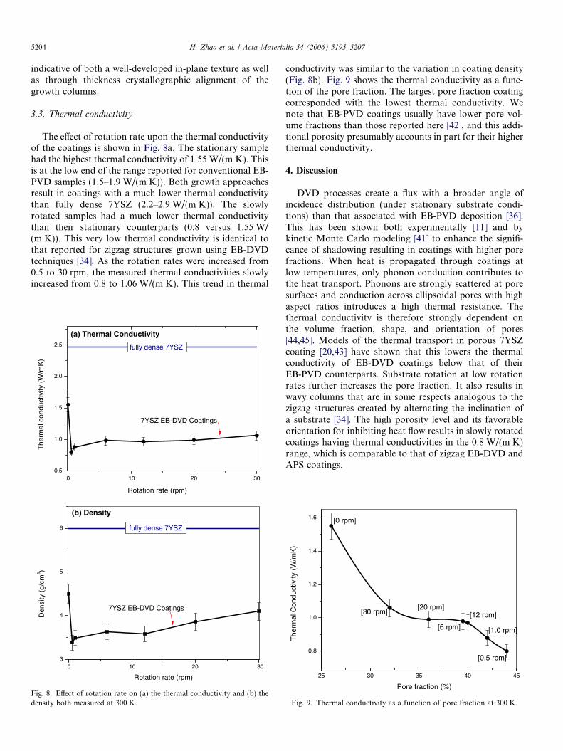
The effect of rotation rate upon the thermal conductivityof the coatings is shown in Fig. 8a. The stationary samplehad the highest thermal conductivity of 1.55 W/(m K). Thisis at the low end of the range reported for conventional EB-PVD samples (1.5–1.9 W/(m K)). Both growth approachesresult in coatings with a much lower thermal conductivitythan fully dense 7YSZ (2.2–2.9 W/(m K)). The slowlyrotated samples had a much lower thermal conductivitythan their stationary counterparts (0.8 versus 1.55 W/(m K)). This very low thermal conductivity is identical tothat reported for zigzag structures grown using EB-DVDtechniques [34]. As the rotation rates were increased from0.5 to 30 rpm, the measured thermal conductivities slowlyincreased from 0.8 to 1.06 W/(m K). This trend in thermal
0 10 20 300.5
1.0
1.5
2.0
2.5
7YSZ EB-DVD Coatings
The
rmal
con
duct
ivity
(W
/mK
)
Rotation rate (rpm)
fully dense 7YSZ
(a) Thermal Conductivity
0 10 20 303
4
5
6
Den
sity
(g/
cm3 )
Rotation rate (rpm)
(b) Density
fully dense 7YSZ
7YSZ EB-DVD Coatings
Fig. 8. Effect of rotation rate on (a) the thermal conductivity and (b) thedensity both measured at 300 K.
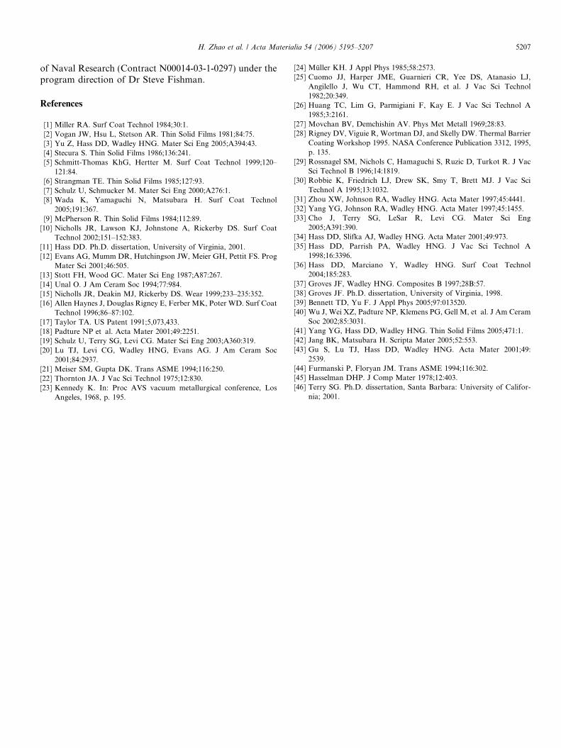
conductivity was similar to the variation in coating density(Fig. 8b). Fig. 9 shows the thermal conductivity as a func-tion of the pore fraction. The largest pore fraction coatingcorresponded with the lowest thermal conductivity. Wenote that EB-PVD coatings usually have lower pore vol-ume fractions than those reported here [42], and this addi-tional porosity presumably accounts in part for their higherthermal conductivity.
4. Discussion
DVD processes create a flux with a broader angle ofincidence distribution (under stationary substrate condi-tions) than that associated with EB-PVD deposition [36].This has been shown both experimentally [11] and bykinetic Monte Carlo modeling [41] to enhance the signifi-cance of shadowing resulting in coatings with higher porefractions. When heat is propagated through coatings atlow temperatures, only phonon conduction contributes tothe heat transport. Phonons are strongly scattered at poresurfaces and conduction across ellipsoidal pores with highaspect ratios introduces a high thermal resistance. Thethermal conductivity is therefore strongly dependent onthe volume fraction, shape, and orientation of pores[44,45]. Models of the thermal transport in porous 7YSZcoating [20,43] have shown that this lowers the thermalconductivity of EB-DVD coatings below that of theirEB-PVD counterparts. Substrate rotation at low rotationrates further increases the pore fraction. It also results inwavy columns that are in some respects analogous to thezigzag structures created by alternating the inclination ofa substrate [34]. The high porosity level and its favorableorientation for inhibiting heat flow results in slowly rotatedcoatings having thermal conductivities in the 0.8 W/(m K)range, which is comparable to that of zigzag EB-DVD andAPS coatings.
25 30 35 40 45
0.8
1.0
1.2
1.4
1.6
[12 rpm]
[6 rpm]
[30 rpm][20 rpm]
[1.0 rpm]
[0.5 rpm]
The
rmal
Con
duct
ivity
(W
/mK
)
Pore fraction (%)
[0 rpm]
Fig. 9. Thermal conductivity as a function of pore fraction at 300 K.

Fig. 10. Column tip orientation during the column growth.
H. Zhao et al. / Acta Materialia 54 (2006) 5195–5207 5205
At low rotation rates, Type I pores are elongated andbent perpendicular to the growth direction making themlonger than those in the stationary sample. The width ofthe pores is also greater. In the slowly rotated samples withwavy columns, the conduction distance is increased con-tributing to a significant impediment to the heat flow. Arecent analytical study of heat conduction across the zigzagstructures [20] indicated that inclined Type I pores werehighly effective at disrupting through-thickness thermaltransport. These models suggest that the low thermal con-ductivity of the C-shaped microstructures is dominated bycontinuous Type I and II pores even though their porefraction is low; Type III pores, due to their random orien-tations in slowly rotated samples may introduce a relativelysmaller effect upon the overall conductivity.
Increasing the rate of rotation significantly reduces thetotal pore fraction (Fig. 8b), but the thermal conductivityis restored much more slowly (Fig. 8a). Fig. 9 links thethermal conductivity to the pore volume fraction and indi-cates that in the 30–40% pore fraction range, the thermalconductivity is a weak function of pore fraction. The rap-idly rotated EB-DVD coatings explored here thereforeretain a much low thermal conductivity than their EB-PVD counterparts. The weak dependence of thermal con-ductivity upon rotation rate in the 5–30 rpm range appearsto be the result of a change in the Type III pore morphol-ogy with increase in rotation rate.
At higher rotation rate, the Type I and II pores are ver-tically aligned and were not greatly affected by the sub-strate rotation. We therefore expect the contribution ofthese pores to the change in thermal resistance to be small.The retention of a low thermal conductivity in the morerapidly rotated samples must therefore be linked to achange in the morphology of Type III pores that makesthem more effectively at impeding thermal flux transport.By comparing Fig. 5a and c, it can be seen that as the rota-tion rate increased, the Type III pores became alignedtransverse to the growth columns in an orientation thatwould be highly effective at disrupting the flow of heatalong the primary growth columns.
The significant changes in pore morphology that accom-panied an increase in rotation rate were also correlatedwith a change in column growth direction from Æ111æ toÆ001æ. Similar texture changes have been reported forEB-PVD coatings [8]. Schultz et al. [19] have developed acompetitive facet growth (STL) model to account for theseEB-PVD observations. Briefly, in the evolutionary selec-tion process, during deposition of a thick film, for whichgrowth is characterized by evolutionary selection, thestructure will be dominated by grains through the thicknessof the film having nearly the same ‘‘fast growth’’ axis,resulting in a strong fiber texture to the film.
Stationary samples have the Æ11 1æ preferred growthdirection with growth columns capped by pyramidal typetips (Fig. 10a). Under constrained surface diffusion condi-tions, stable columnar growth requires that each of the fac-ets of a column tip receive equal amounts of vapor flux.
This condition is referred to as the ‘‘equal flux’’ require-ment in the STL model [19,46]. Unfavorable columnarmorphologies which do not satisfy the equal flux conditionwill be screened out by evolutionary selection. Experiments[46] indicate that stationary samples with oblique vaporincidence angle (45�) have a (two-sided) rooftop columntip morphology formed by the intersection of two {11 1}facets. The resulting column axis is then Æ110æ direction.When such a rooftop ridge is parallel to the vapor inci-dence plane, each {111} facet can receive equal vaporfluxes and growth of such a structure satisfies the ‘‘equalflux’’ condition. Coatings grown with substrate rotationhave a Æ1 00æ column axis orientation with the columnscapped by four {111} planes. This is consistent with theSTL model, since opposing pairs of facets sequentiallyreceive equal fluxes as the growth column axis rotates from�90� to 0� and then 0� to 90� (Fig. 11). Each period can belikened to an equivalent oblique incidence flux. The twohalf periods of vapor incidence angle result in equal vaporflux for the period of exposure to a different pair of rooftopcolumn tips bounded by {111} facets with their bisectorsthen in a Æ110æ direction. Square-pyramidal facet tip col-umns are formed with a column axis in a Æ1 00æ direction(Fig. 10b).
During the growth of these columns, the formation ofporosity results from flux shadowing and the Type III poremorphology reflects a complicated interplay between theactual flux that intercepts the local growth surface andthe fast growth directions of the columns. Substrate rota-tion broadens the vapor incidence angle distribution andthus promotes the shadowing. The broader flux distribu-tion of the EB-DVD process appears to further enhancethis shadowing. The EB-DVD rotated substrate samplestherefore have a high volume fraction of ‘‘feather-like’’Type III pores that can be seen at the edge of columns.They are also orientated in a plane that is highly effectiveat disrupting thermal conduction along the column axis.

Fig. 11. Formation of square pyramidal column tip under the condition of rotated substrate.
5206 H. Zhao et al. / Acta Materialia 54 (2006) 5195–5207
5. Conclusions
An EB-DVD approach has been used to grow 7YSZcoatings and the effects of substrate rotation upon the coat-ing density, pore morphology, and texture of the coatingswere investigated and related to changes of thermal con-ductivity. We find that:
1. During stationary deposition, straight-sided growth col-umns are formed with triangular column faceted tips.Rotated samples have growth columns with squarepyramidal faceted tips. This difference is accompaniedby a change in preferred crystallographic growth direc-tion from Æ111æ to Æ100æ as the substrate rotation rateincreases.
2. At low rotation rates, wavy columnar structure formsdue to the slow rate of change of the incidence angleof the vapor flux to the substrate. The increased con-duction distance along the wavy columns combinedwith a high pore volume fraction results in a verylow thermal conductivity of 0.8 W/(m K) which is wellbelow that of conventionally EB-PVD depositedcoatings.
3. At high rotation rates, the wavy columns disappear andrelatively straight-sided columns are formed in the coat-ing. These coatings have thermal conductivities in theregion of 1 W/(m K) which is 50% less than thatreported for EB-PVD coatings grown under otherwisesimilar conditions. The low thermal conductivity ofthe rotated EB-DVD coatings appears to be a result ofan increased volume fraction of Type III nanopores inthe primary and secondary growth columns orientatedtransversely to the heat flow direction.
Acknowledgements
We are grateful to Prof. Carlos Levi at University ofCalifornia Santa Barbara for helpful discussions duringthe conduct of this study. We also thank Dave Wortmanof GE Aircraft Engines for kindly providing substrates.Thermal conductivity measurements used in this investiga-tion were funded by the National Science Foundationunder grant DMR-0099695, as part of a program of inter-national collaboration with the European Commission(GRD2-200-30211). This work was supported by the Office
H. Zhao et al. / Acta Materialia 54 (2006) 5195–5207 5207
of Naval Research (Contract N00014-03-1-0297) under theprogram direction of Dr Steve Fishman.
References
[1] Miller RA. Surf Coat Technol 1984;30:1.[2] Vogan JW, Hsu L, Stetson AR. Thin Solid Films 1981;84:75.[3] Yu Z, Hass DD, Wadley HNG. Mater Sci Eng 2005;A394:43.[4] Stecura S. Thin Solid Films 1986;136:241.[5] Schmitt-Thomas KhG, Hertter M. Surf Coat Technol 1999;120–
121:84.[6] Strangman TE. Thin Solid Films 1985;127:93.[7] Schulz U, Schmucker M. Mater Sci Eng 2000;A276:1.[8] Wada K, Yamaguchi N, Matsubara H. Surf Coat Technol
2005;191:367.[9] McPherson R. Thin Solid Films 1984;112:89.
[10] Nicholls JR, Lawson KJ, Johnstone A, Rickerby DS. Surf CoatTechnol 2002;151–152:383.
[11] Hass DD. Ph.D. dissertation, University of Virginia, 2001.[12] Evans AG, Mumm DR, Hutchingson JW, Meier GH, Pettit FS. Prog
Mater Sci 2001;46:505.[13] Stott FH, Wood GC. Mater Sci Eng 1987;A87:267.[14] Unal O. J Am Ceram Soc 1994;77:984.[15] Nicholls JR, Deakin MJ, Rickerby DS. Wear 1999;233–235:352.[16] Allen Haynes J, Douglas Rigney E, Ferber MK, Poter WD. Surf Coat
Technol 1996;86–87:102.[17] Taylor TA. US Patent 1991;5,073,433.[18] Padture NP et al. Acta Mater 2001;49:2251.[19] Schulz U, Terry SG, Levi CG. Mater Sci Eng 2003;A360:319.[20] Lu TJ, Levi CG, Wadley HNG, Evans AG. J Am Ceram Soc
2001;84:2937.[21] Meiser SM, Gupta DK. Trans ASME 1994;116:250.[22] Thornton JA. J Vac Sci Technol 1975;12:830.[23] Kennedy K. In: Proc AVS vacuum metallurgical conference, Los
Angeles, 1968, p. 195.
[24] Muller KH. J Appl Phys 1985;58:2573.[25] Cuomo JJ, Harper JME, Guarnieri CR, Yee DS, Atanasio LJ,
Angilello J, Wu CT, Hammond RH, et al. J Vac Sci Technol1982;20:349.
[26] Huang TC, Lim G, Parmigiani F, Kay E. J Vac Sci Technol A1985;3:2161.
[27] Movchan BV, Demchishin AV. Phys Met Metall 1969;28:83.[28] Rigney DV, Viguie R, Wortman DJ, and Skelly DW. Thermal Barrier
Coating Workshop 1995. NASA Conference Publication 3312, 1995,p. 135.
[29] Rossnagel SM, Nichols C, Hamaguchi S, Ruzic D, Turkot R. J VacSci Technol B 1996;14:1819.
[30] Robbie K, Friedrich LJ, Drew SK, Smy T, Brett MJ. J Vac SciTechnol A 1995;13:1032.
[31] Zhou XW, Johnson RA, Wadley HNG. Acta Mater 1997;45:4441.[32] Yang YG, Johnson RA, Wadley HNG. Acta Mater 1997;45:1455.[33] Cho J, Terry SG, LeSar R, Levi CG. Mater Sci Eng
2005;A391:390.[34] Hass DD, Slifka AJ, Wadley HNG. Acta Mater 2001;49:973.[35] Hass DD, Parrish PA, Wadley HNG. J Vac Sci Technol A
1998;16:3396.[36] Hass DD, Marciano Y, Wadley HNG. Surf Coat Technol
2004;185:283.[37] Groves JF, Wadley HNG. Composites B 1997;28B:57.[38] Groves JF. Ph.D. dissertation, University of Virginia, 1998.[39] Bennett TD, Yu F. J Appl Phys 2005;97:013520.[40] Wu J, Wei XZ, Padture NP, Klemens PG, Gell M, et al. J Am Ceram
Soc 2002;85:3031.[41] Yang YG, Hass DD, Wadley HNG. Thin Solid Films 2005;471:1.[42] Jang BK, Matsubara H. Scripta Mater 2005;52:553.[43] Gu S, Lu TJ, Hass DD, Wadley HNG. Acta Mater 2001;49:
2539.[44] Furmanski P, Floryan JM. Trans ASME 1994;116:302.[45] Hasselman DHP. J Comp Mater 1978;12:403.[46] Terry SG. Ph.D. dissertation, Santa Barbara: University of Califor-
nia; 2001.