Monte Carlo simulations for optimization of neutron shielding concrete
8
Cent. Eur. J. Eng. • 2(2) • 2012 • 296-303 DOI: 10.2478/s13531-011-0063-0 Monte Carlo simulations for optimization of neutron shielding concrete Tomasz Piotrowski 1* , Dariusz B. Tefelski 2 , Aleksander Polański 3 , Janusz Skubalski 4 1 Warsaw University of Technology, Faculty of Civil Engineering, Al.Armii Ludowej 16, PL 00637 Warsaw, Poland 2 Warsaw University of Technology, Faculty of Physics, Koszykowa 75, PL 00662 Warsaw, Poland 3 The Andrzej Soltan Institute for Nuclear Studies, Department of Interdisciplinary Applications of Physics PL 05400 Świerk/Otwock, Poland 3 University of Lódź, Faculty of Physics and Applied Informatics, Pomorska 149/153 PL 90236 Lódź, Poland Concrete is one of the main materials used for gamma and neutron shielding. While in case of gamma rays an increase in density is usually efficient enough, protection against neutrons is more complex. The aim of this paper is to show the possibility of using the Monte Carlo codes for evaluation and optimization of concrete mix to reach better neutron shielding. Two codes (MCNPX and SPOT – written by authors) were used to simulate neutron transport through a wall made of different concretes. It is showed that concrete of higher compressive strength attenuates neutrons more effectively. The advantage of heavyweight concrete (with barite aggregate), usually used for gamma shielding, over the ordinary concrete was not so clear. Neutron shielding depends on many factors e.g. neutron energy, barrier thickness and atomic composition. All this makes a proper design of concrete as a very important issue for nuclear power plant safety assurance. Radiation protection • Concrete design and optimization • Monte Carlo © Versita sp. z o.o. 1. Introduction One of the main radiation shielding materials used in nuclear power plants is a cement concrete. It attenuates both gamma and neutron radiations. One of the main advantages of concrete, in comparison to the others, is that it is a composite-type material and there is a possibility to optimize its constituents and mix proportions for better properties. Optimization has already been widely used in * E-mail: [email protected] concrete mix design for better mechanical properties but in radiation protection the geometry of barriers is designed not due to the static conditions but due to efficiency of shielding properties of an element. In general, it leads to massive structures which cost are not negligible. Most of all, facilities space and weight reduction is desirable. Ordinary concrete of a density = 2000 ÷ 2600 / 3 , is a mixture of cement, coarse and fine aggregate, water and eventually additives and admixtures that are set by cement hydratation. Usually for shielding barrier a heavyweight concrete (> 2600 / 3 ) is used. It is obtained by addition of heavy components (mainly aggregate and fillers) like basalt, magnetite, barite, limonite, iron and metal
-
Upload
tomasz-piotrowski -
Category
Documents
-
view
229 -
download
0
Transcript of Monte Carlo simulations for optimization of neutron shielding concrete

Cent. Eur. J. Eng. • 2(2) • 2012 • 296-303DOI: 10.2478/s13531-011-0063-0
Central European Journal of Engineering
Monte Carlo simulations for optimization of neutronshielding concrete
Research article
Tomasz Piotrowski1∗, Dariusz B. Tefelski2, Aleksander Polański3, Janusz Skubalski4
1 Warsaw University of Technology, Faculty of Civil Engineering, Al.Armii Ludowej 16, PL 00637 Warsaw, Poland
2 Warsaw University of Technology, Faculty of Physics, Koszykowa 75, PL 00662 Warsaw, Poland
3 The Andrzej Sołtan Institute for Nuclear Studies, Department of Interdisciplinary Applications of PhysicsPL 05400 Świerk/Otwock, Poland
3 University of Łódź, Faculty of Physics and Applied Informatics, Pomorska 149/153 PL 90236 Łódź, Poland
Received 30 June 2011; accepted 09 January 2012
Abstract: Concrete is one of the main materials used for gamma and neutron shielding. While in case of gamma rays anincrease in density is usually efficient enough, protection against neutrons is more complex. The aim of this paperis to show the possibility of using the Monte Carlo codes for evaluation and optimization of concrete mix to reachbetter neutron shielding. Two codes (MCNPX and SPOT – written by authors) were used to simulate neutrontransport through a wall made of different concretes. It is showed that concrete of higher compressive strengthattenuates neutrons more effectively. The advantage of heavyweight concrete (with barite aggregate), usually usedfor gamma shielding, over the ordinary concrete was not so clear. Neutron shielding depends on many factors e.g.neutron energy, barrier thickness and atomic composition. All this makes a proper design of concrete as a veryimportant issue for nuclear power plant safety assurance.
Keywords: Radiation protection • Concrete design and optimization • Monte Carlo© Versita sp. z o.o.
1. Introduction
One of the main radiation shielding materials used innuclear power plants is a cement concrete. It attenuatesboth gamma and neutron radiations. One of the mainadvantages of concrete, in comparison to the others, is thatit is a composite-type material and there is a possibilityto optimize its constituents and mix proportions for betterproperties. Optimization has already been widely used in∗E-mail: [email protected]
concrete mix design for better mechanical properties but inradiation protection the geometry of barriers is designednot due to the static conditions but due to efficiency ofshielding properties of an element. In general, it leadsto massive structures which cost are not negligible. Mostof all, facilities space and weight reduction is desirable.Ordinary concrete of a density ρ = 2000 ÷ 2600 kg/m3, isa mixture of cement, coarse and fine aggregate, water andeventually additives and admixtures that are set by cementhydratation. Usually for shielding barrier a heavyweightconcrete (ρ > 2600 kg/m3) is used. It is obtained byaddition of heavy components (mainly aggregate and fillers)like basalt, magnetite, barite, limonite, iron and metal296

T. Piotrowski, D.B. Tefelski, A. Polański, J. Skubalski
ash and slag. The report [1] presents the analysis ofconcrete components for The MARIA nuclear reactor andfor The Żarnowiec nuclear power plant with domestic polishsand, gravel and cement. The goal is to achieve betterradiation shielding properties with no increase in weightas well as improvement or no loss in other propertiese.g. compressive strength and durability. The aim of thispaper is to show the possibility of using the Monte Carlo(MC) simulation codes for evaluation and optimizationof concrete mix to reach better neutron shielding. Theperformance of neutron shielding concrete has alreadybeen simulated and investigated experimentally by Okunoet al [2]. Gallego et al [3] compared experimental resultsusing 241Am-Be neutron soures to MCNP5 calculationresutls (MCNP5 is the same package as MCNPX [4] forlow energy neutrons: less than 20 MeV) and they foundsome differences with regard to the experiments. In thispaper, only theoretical study was presented. Authors areplanning an experimental verification of the SPOT resultson real samples of concrete of different compositions in areal neutron fluxes. This work is than an entry point forfurther experimental data validation.2. Monte Carlo simulationsIn Poland SAMSY [5] numerical programs as well asANISN [6], DOT [7], MORSE [8] and MCNP/MCNPX[9] have been the most commonly used to design the shieldagainst the radiation of nuclear facilities, such as theMARIA nuclear reactor in Świerk and The Żarnowiec nu-clear power plant [1], the accelerator in the SINS andsub-critical assembly SAD [10]. These programs allow forthe solution of Boltzmann transport equation using remove-diffusion method (SAMSY), discrete ordinates method(ANISN, DOT) or the Monte Carlo (MC) method (MORSE,MCNP). However, the solution of complex shielding prob-lems in a nuclear reactor uses a combination of programsbased on the method of discrete ordinates and schemesbased on the MC method. In this case, DOT programsare used for calculation of two-dimensional distribution ofneutron radiation and gamma rays in a reactor core, whileprograms based on the MC method in the other parts of theobject. It should be mentioned, that simultaneously to thedevelopment of computational methods and numerical pro-grams, work on nuclear cross sections is beeing conducted.In this paper, the core of nuclear reactor was calculatedwith APOLLO 2 [11] and shielding using MC software withENDF/B nuclear data as the cover for calculations. MCsimulation method is one of the most reliable methods fordetermining the ability of materials to shield against theradiation. Calzada et al [12] already used MC simulationsto optimize the composition of new shielding material com-
posed of steel resin, paraffin/polyethylene and a boroncompound that radiation attenuation is higher comparedto heavy weight concrete. This method is a statisticalmethod based on the pseudo-random number generator,the cross sections for reactions in material already knownand the assumed model of particle motion. A complete setof simulation must also include a geometry of the shieldingmaterial, an atomic composition of material, parameters ofradioactive source and a type and a placement of radiationdetectors. The MC simulation method has one importantdrawback - the real time of simulation significantly in-creases when more accurate data has to be calculated,especially when high complexity test system is considered.The most advanced MC computational package is MC-NPX [4] from Los Alamos National Laboratory. It is veryflexible package, which can be used in many applications[13] including shielding analysis [14]. In this paper, datafrom simulation of neutron transport in concrete shields us-ing MCNPX and also authors’ simulation software calledSPOT are presented. SPOT, a quite simple software forengineering calculations, was prepared using the assump-tions of MCNPX software, but including only the elasticneutron scattering and absorption in the model. The ad-vantage of SPOT is a wide range of possible modifications.A semi-quantitative agreement between data obtained fromSPOT and MCNPX was obtained up to 2.0 MeV of neutroninitial energy (Fig. 1a). It is consistent with the modelused, because in this energy range, the elastic scatteringprocess is dominating in neutron collisions with atoms.The comparison of 1.0 MeV neutron flux depending onthickness of concrete shield for SPOT and MCNPX showsthat obtained results are in good agreement (Fig. 1b).Calculations in MCNPX were performed for 107 neutronhistories, whereas in SPOT were performed for 10 batchesof 105 histories. In MCNPX nuclear data was included fromENDF/B-VI.0, ENDF/B-VI.8, ENDF/B-VII.0 databases. InSPOT, the ENDF/B-VI.8 databases were used (JANIS [15]software was used to extract cross sections). No variance-reduction techniques were applied. The basic steps ofMC neutron transport simulation consists of a particlegeneration (initial energy, position and direction in thedomain of θ, φ angles tossed from pseudo–random numbergenerator – RNG). Next step is a transport code. Fornon-charged particle like neutron it is a straight line witha distance acquired from RNG with use of exponentialdistribution. Distance is easily calculated from equation 1.d = − 1Σt ln(x) (1)
where x is a number from RNG (linear distribution), Σt ismacroscopic total cross-section of medium.Then particle interactions are considered in a manner ofRNG with use of correct cross-sections. In case of SPOT297

Monte Carlo simulations for optimization of neutron shielding concrete
Tomasz Piotrowski, Dariusz B. Tefelski, Aleksander Polanski, Janusz Skubalski
a)
80 85 90 95
100 105
0.1 1 10
Ra
tio
S/M
, %
Incident neutron energy [MeV]
0.3
0.4
0.5
0.6
0.7N
/N0
Material: OCEM1 thickness: 10cm
SPOTMCNPX
b)
0
2e-06
4e-06
6e-06
8e-06
1e-05
1.2e-05
1.4e-05
1.6e-05
10 20 30 40 50 60
Ne
utr
on
flu
x [
cm
-2*s
-1]
Shield thickness [cm]
Neutron flux. E=1MeV. Material: OCEM1
SPOTMCNPX
Figure 1. SPOT and MCNPX comparison: a) neutron transmittance vs. incident neutron energy for 10 cm concretethickness, b) neutron flux for 1.0 MeV incident neutron energy transmittance vs. concrete thickness
cross sections for reactions in material already known and the assumed model of particle motion. A complete
set of simulation must also include a geometry of the shielding material, an atomic composition of material,
parameters of radioactive source and a type and a placement of radiation detectors. The MC simulation method
has one important drawback - the real time of simulation significantly increases when more accurate data has to
be calculated, especially when high complexity test system is considered. The most advanced MC computational
package is MCNPX [4] from Los Alamos National Laboratory. It is very flexible package, which can be used in
many applications [13] including shielding analysis [14]. In this paper, data from simulation of neutron transport
in concrete shields using MCNPX and also authors’ simulation software called SPOT are presented. SPOT, a
quite simple software for engineering calculations, was prepared using the assumptions of MCNPX software, but
including only the elastic neutron scattering and absorption in the model. The advantage of SPOT is a wide
range of possible modifications. A semi-quantitative agreement between data obtained from SPOT and MCNPX
was obtained up to 2.0 MeV of neutron initial energy (Fig.1a). It is consistent with the model used, because in
this energy range, the elastic scattering process is dominating in neutron collisions with atoms. The comparison
of 1.0 MeV neutron flux depending on thickness of concrete shield for SPOT and MCNPX shows that obtained
results are in good agreement (Fig.1b).
Calculations in MCNPX were performed for 107 neutron histories, whereas in SPOT were performed for 10
batches of 105 histories. In MCNPX nuclear data was included from ENDF/B-VI.0, ENDF/B-VI.8, ENDF/B-
VII.0 databases. In SPOT, the ENDF/B-VI.8 databases were used (JANIS [15] software was used to extract cross
sections). No variance-reduction techniques were applied. The basic steps of MC neutron transport simulation
consists of a particle generation (initial energy, position and direction in the domain of θ, φ angles tossed from
pseudo–random number generator – RNG). Next step is a transport code. For non–charged particle like neutron
it is a straight line with a distance acquired from RNG with use of exponential distribution. Distance is easily
(a)
Tomasz Piotrowski, Dariusz B. Tefelski, Aleksander Polanski, Janusz Skubalski
10
b)
0
2e-06
4e-06
6e-06
8e-06
1e-05
1.2e-05
1.4e-05
1.6e-05
10 20 30 40 50 60
Ne
utr
on
flu
x [
cm
-2*s
-1]
Shield thickness [cm]
Neutron flux. E=1MeV. Material: OCEM1
SPOTMCNPX
SPOT and MCNPX comparison: a) neutron transmittance vs. incident neutron energy for 10 cm concretethickness, b) neutron flux for 1.0 MeV incident neutron energy transmittance vs. concrete thickness
cross sections for reactions in material already known and the assumed model of particle motion. A complete
set of simulation must also include a geometry of the shielding material, an atomic composition of material,
parameters of radioactive source and a type and a placement of radiation detectors. The MC simulation method
has one important drawback - the real time of simulation significantly increases when more accurate data has to
be calculated, especially when high complexity test system is considered. The most advanced MC computational
] from Los Alamos National Laboratory. It is very flexible package, which can be used in
] including shielding analysis [14]. In this paper, data from simulation of neutron transport
in concrete shields using MCNPX and also authors’ simulation software called SPOT are presented. SPOT, a
quite simple software for engineering calculations, was prepared using the assumptions of MCNPX software, but
including only the elastic neutron scattering and absorption in the model. The advantage of SPOT is a wide
range of possible modifications. A semi-quantitative agreement between data obtained from SPOT and MCNPX
was obtained up to 2.0 MeV of neutron initial energy (Fig.1a). It is consistent with the model used, because in
this energy range, the elastic scattering process is dominating in neutron collisions with atoms. The comparison
of 1.0 MeV neutron flux depending on thickness of concrete shield for SPOT and MCNPX shows that obtained
Calculations in MCNPX were performed for 107 neutron histories, whereas in SPOT were performed for 10
(b)Figure 1. SPOT and MCNPX comparison: a) neutron transmittance
vs. incident neutron energy for 10 cm concrete thickness,b) neutron flux for 1.0 MeV incident neutron energy trans-mittance vs. concrete thickness.
only absorption and elastic scattering was consideredwhereas in MCNPX a lot of interactions are possible, likeproduction of neutrons (n, 2n), (n, 3n), (n, xn), gamma rays,electrons, particles (d, t, α, ...), ions and heavy-ions. Insuch cases another particle tracks are generated. Alsophotons and other particles like light ions may be gener-ated. For example, if elastic scattering is chosen, a nuclideshould be tossed with use of macroscopic cross-sections.MCNPX uses many advanced modelling techniques likethermal treatment based on the free gas aproximation,chemical binding, crystal structure influcence, and cross-section data are corrected accordingly to the simulationconditions. In case of elastic scattering the particle energyloss is generally obtained from momentum and energy con-servation principles in a center of mass frame. Then a new”motion” is started with angle generated by RNG usingdifferential angular cross-sections. Theses steps are re-peated until an absorption is chosen or particle leaves thematerial. In this case particle counter is increased, flux isupdated and for SPOT equivalent dose is updated. In caseof MCNPX histogram of selected energy bins is created
and on this basis equivalent dose is calculated in exter-nal program. In MCNPX there are many physics modelscodes like inner nucleus cascades which helps obtainingcorrect solution within high energy ranges. For inelasticscattering, there are many laws incorporated. There arephoto effect, pair production, Compton effect, electron in-teractions like Bremstrahlung, Auger transitions and soon. MCNPX can be used in wide areas of nuclear physicssimulation. The SPOT program is a very thin subset of this,but quite useful for our simulation conditions (energy up to2.0 MeV, only neutron transport). SPOT is also not suitedfor complex medium geometry but suited for calculation ofneutron transport in inhomogeneous medium. The properimprovement is under preparation stage.3. Shielding concrete optimizationLately a big progress in concrete evolution has been made.It is mostly due to use of polymer additives (e.g. super-plasticizers) together with reactive additions (e.g. silicafume), that allows for decrease of w/c ratio, increase oftightness and mechanical properties without loss in worka-bility of fresh concrete mix. Also an intensive developmentof Polymer-Cement Concrete (PCC) in the last decade hasbeen observed [16]. This progress allows for a new lookat the concrete optimization for better radiation shieldingproperties. Already some calculations and investigationson shielding (mainly against gamma rays) has been made.Akkurt et al. [17] proved that the type of the aggregate ismore important than the amount of aggregate for gammaray shielding and the barite-loaded concretes would bepreferred for this purpose. Sato et al. [18] proposed fora radioactive waste management a multilayered concretestructures with boron-doped low activation concrete wall.Here a flexible neutron shielding resin, recently developedby Sukegawa et al. [19], could be used. This solutioncould be problematic in a reactor building constructiondue to the particularity of concrete works technology andproblems that can arise at the interface like it happensin multilayer repair systems [20]. Bashter [21], apart fromgamma shielding analyses, showed that calculated effectivemacroscopic neutron removal cross-sections for six differ-ent concretes can be increased up to 50% with relation toordinary one by a change of an aggregate type. Measuredvalues differs from the calculated ones within the range13.5 ÷ 33.7%. It shows that while in case of gamma ra-diation an increase in density by a change of aggregateis usually efficient enough, protection against neutrons ismore complex. It is due to the differences in interactions offree neutrons with the matter, depending on their kineticenergy and cross-sections for different reactions of thecomponent atoms of the cement paste and the aggregate.
298

T. Piotrowski, D.B. Tefelski, A. Polański, J. Skubalski
Some general recommendations can be presented here e.g.increase of hydrogen content in concrete (more chemicallybounded water) or addition of neutron absorbers (boron).It is worth to mention that shielding process and its in-tensity against different radiation depends not only onthe chemical composition but the structure of the barrier(e.g. heterogeneites) [22] and local defects (e.g. cracks) aswell [23].4. Dose calculationIn radiation protection doses refer mostly to absorbeddose and relate to the X-rays and gamma rays. Formally,absorbed dose D, is defined by equation (2) as a measureof the energy deposited in a medium by ionizing radiation:
D = ∆E∆m[Jkg = Gy (gray)] (2)
where: ∆E – the mean energy imparted by ionizing ra-diation to matter in a volume element, ∆m – the mass ofmatter in the volume element.However, the biological effects do not depend only on theabsorbed dose but on the sensitivity of particular organsor tissues and the radiation type as well. Radiation typeis described by the ionization density (numbers of ionsproduced in the individual path of radiation). Thereforethe two doses are defined, which take into considerationall these aspects. The equivalent dose HT takes intoconsideration the radiation type (by multiplication factorwR ) and the effective dose DE takes into consideration thesensitivity of individual organs or tissues to radiation (bymultiplication factor wT ). The equivalent dose is definedby equation (3):
HT = wR ·DT (3)where: DT - the absorbed dose delivered by radiation typeR averaged over a tissue or organ T , wR - the radiationweighting factor for radiation type R .The effective dose (4) is a summation of tissue equivalentdoses multiplied by the appropriate tissue weighting factor:
DE =∑wT ·HT (4)where: HT - the equivalent dose in tissue T , wT - thetissue weighting factor for tissue T .In the Polish legal system, the binding values of radiationweighting factors (Tab. 1) and tissue weighting factors(Tab. 2) are given in the Regulation of the Council ofMinisters [24] in accordance with the recommendations ofICRP [25]. When effective dose for all body is calculated,
Table 1. Radiation weighting factors wR [24].
Radiation type and energy Radiation weighting factor, wRPhotons, all energies 1Electrons, myons, all energies 1Neutrons below 10 keV 5from 10 keV to 100 keV 10from 100 keV to 2 MeV 20from 2 MeV to 20 MeV 10over 20 MeV 5Protons over 2 MeV 5Alpha particles, fission fragments,heavy nuclei 20Table 2. Tissue weighting factor wT [24].
Tissue (organ), T Tissue (organ)weighting factor, wTGonads 0.20Bone marrow (red) 0.12Colon 0.12Lung 0.12Stomach 0.12Bladder 0.05Chest 0.05Liver 0.05Oesophagus 0.05Thyroid gland 0.05Skin 0.01Bone surface 0.01Adrenals, brain, small intestine, kidneymuscle, pancreas,spleen, thymus, uterus(the weighting factor 0.05 is applied tothe average dose of these organs) 0.05
Neutrons below 10 keV 5
from 10 keV to 100 keV 10
from 100 keV to 2 MeV 20
from 2 MeV to 20 MeV 10
over 20 MeV 5
Protons over 2 MeV 5
Alpha particles, fission fragments, heavy nuclei 20
Table 2. Tissue weighting factor wT [24]
Tissue (organ), T Tissue (organ) weighting factor,wT
Gonads 0.20
Bone marrow (red) 0.12
Colon 0.12
Lung 0.12
Stomach 0.12
Bladder 0.05
Chest 0.05
Liver 0.05
Oesophagus 0.05
Thyroid gland 0.05
Skin 0.01
Bone surface 0.01
Adrenals, brain, small intestine, kidney 0.05
muscle, pancreas,spleen, thymus, uterus
(the weighting factor 0.05 is applied to
the average dose of these organs)
Figure 2. The model of effective dose calculation used in this paper. N - number of neutron energy groups,E - neutron energy
6
Figure 2. The model of effective dose calculation used in this paper.N – number of neutron energy groups, DE – effective dose,E – neutron energy.

Monte Carlo simulations for optimization of neutron shielding concrete
Table 3. The conversion coefficients CCn as the effective dose perunit fluence.Energy CCn Energy CCn Energy CCn[MeV ] [pSv · cm2] [MeV ] [pSv · cm2] [MeV ] [pSv · cm2]1.0E-09 2.40 1.0E-03 6.04 1.2 1301.0E-08 2.89 2.0E-03 6.05 2.0 1782.5E-08 3.30 5.0E-03 6.52 3.0 2221.0E-07 4.13 0.01 7.70 4.0 2502.0E-07 4.59 0.02 10.2 5.0 2725.0E-07 5.20 0.03 12.7 6.0 2821.0E-06 5.63 0.05 17.3 7.0 2902.0E-06 5.96 0.07 21.5 8.0 2975.0E-06 6.28 0.10 27.2 9.0 3031.0E-05 6.44 0.15 35.2 10 3092.0E-05 6.51 0.20 42.4 12 3225.0E-05 6.51 0.30 54.7 14 3331.0E-04 6.45 0.50 75.0 15 3382.0E-04 6.32 0.70 92.8 16 3425.0E-04 6.14 0.90 108 18 3451.00 116 20 343
it corresponds to the equivalent dose because a sum ofall tissue weighting factors is equal to 1 (∑wT = 1). Inthis paper the effective doses were determined using theneutron flux and the conversion coefficients CCn as theeffective dose per unit fluence (Fig. 2). The conversioncoefficients (Tab. 3) depend on neutron energy and weretaken from the ICRU Report [26].In the Polish legal system, the binding values of radiationweighting factors (Tab. 1) and tissue weighting factors(Tab. 2) are given in the Regulation of the Council ofMinisters [24] in accordance with the recommendations ofICRP [25]. When effective dose for all body is calculated,it corresponds to the equivalent dose because a sum ofall tissue weighting factors is equal to 1 (∑wT = 1). Inthis paper the effective doses were determined using theneutron flux and the conversion coefficients CCn as theeffective dose per unit fluence (Fig. 2). The conversioncoefficients (Tab. 3) depend on neutron energy and weretaken from the ICRU Report [26].5. Simulation resultsSimulations presented in this paper assumed no cracks andthe homogeneity of concrete (no structural heterogeneitydue to aggregates arrangement) – the atoms were homoge-neously spread in the atomic structure. Obviously it is notalways true, for example in case of poor quality of concreteworks. Next assumption concerns water demand of 25% ofmass of cement used for hydratation. A preliminary studywas a SPOT simulation performed for two separate groupsof concretes of different class of compressive strength; from
Ato
mic
com
posi
tion
Cl 0.01% 0.01% 0.01% 0.01% 0.01% 0.01%
K 0.06% 0.07% 0.08% 0.08% 0.09% 0.11%
Ca 5.59% 6.55% 7.49% 7.22% 8.13% 9.44%
Fe 0.27% 0.32% 0.36% 0.35% 0.40% 0.46%
Figure 3. Effective dose behind 25 cm thick concrete of different compressive strength (SPOT simulation)
8
Figure 3. Effective dose behind 25 cm thick concrete of differentcompressive strength (SPOT simulation).
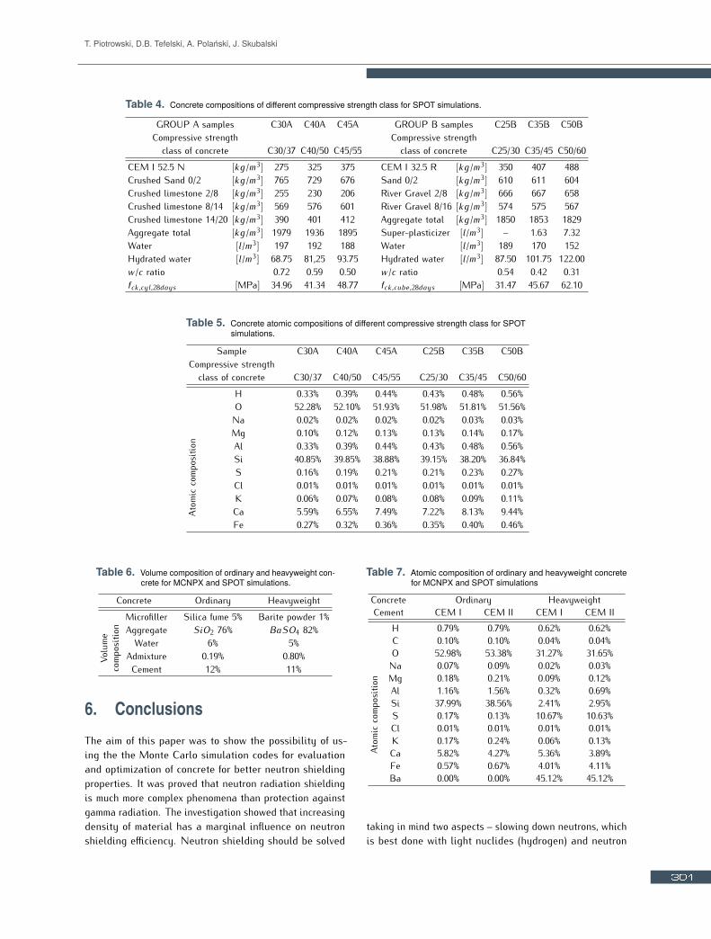
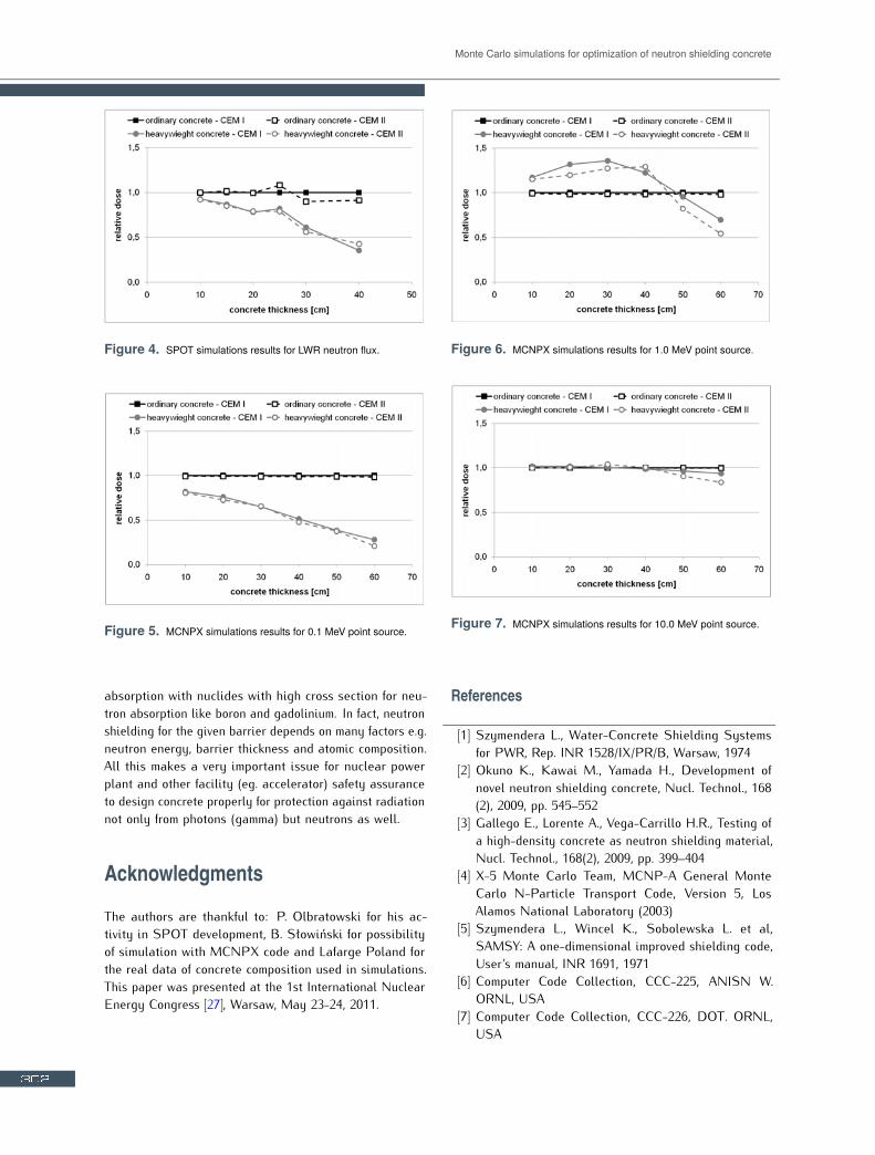
C30/37 to C45/55 (Group A) and from C25/30 to C50/60(Group B). Change in compressive strength class was aresult of different concrete composition (Tab. 4) that leadsto differences in atomic compositions (Tab. 5). Calculationshas been made for a 25 cm thick wall.SPOT simulations source was based on a neutron fluxfrom a Light Water Reactor (LWR) core calculated usingAPOLLO 2. Calculation has been made for 105 histories.Results present a clear decrease in effective dose behindbarrier with an increase in compressive strength of concreteboth for group A and B: 31% and 44% respectively (Fig. 3).The next investigation was made for two types of concrete:ordinary concrete and the heavyweight concrete with barite,that is commonly used for gamma shielding (Tab. 6). Inthese concretes, two different cement classes (CEM I 42.5R and CEM II/B-V 32.5R) were considered. Differences inmix lead to specific atomic concrete compositions (Tab. 7).SPOT simulations source was again a real neutron fluxof 105 histories and ordinary and heavyweight concreteswith CEM I and CEM II of thickness 10 to 40 cm (step5 cm) were investigated. Results are presented in relativedose to ordinary concrete with CEM I. The advantage ofheavyweight concrete is quite clear but a little disturbanceat 25 cm appeared (Fig. 4).MCNPX simulation was performed using a monoenergeticpoint source of 107 histories for ordinary and heavyweightconcrete with CEM I and CEM II and thickness 10 to60 cm (step 10 cm). Results for 0.1 MeV are quite similarto the SPOT ones but the disturbance at 20–30 cm is muchsmaller (Fig. 5). The disturbance in SPOT simulations forreal neutron flux can be explained by the MCNPX resultsfor 1.0 MeV (Fig. 6) and less for 10.0 MeV (Fig. 7) pointsource that are quite different than for 0.1 MeV. The figuresshow that heavyweight concrete is not the best solutionfor 1.0 MeV neutron radiation shielding up to thickness of30–40 cm, where a change in the trend line is observed.
T. Piotrowski, D.B. Tefelski, A. Polański, J. Skubalski
Table 4. Concrete compositions of different compressive strength class for SPOT simulations.
GROUP A samples C30A C40A C45A GROUP B samples C25B C35B C50BCompressive strength Compressive strengthclass of concrete C30/37 C40/50 C45/55 class of concrete C25/30 C35/45 C50/60CEM I 52.5 N [kg/m3] 275 325 375 CEM I 32.5 R [kg/m3] 350 407 488Crushed Sand 0/2 [kg/m3] 765 729 676 Sand 0/2 [kg/m3] 610 611 604Crushed limestone 2/8 [kg/m3] 255 230 206 River Gravel 2/8 [kg/m3] 666 667 658Crushed limestone 8/14 [kg/m3] 569 576 601 River Gravel 8/16 [kg/m3] 574 575 567Crushed limestone 14/20 [kg/m3] 390 401 412 Aggregate total [kg/m3] 1850 1853 1829Aggregate total [kg/m3] 1979 1936 1895 Super-plasticizer [l/m3] – 1.63 7.32Water [l/m3] 197 192 188 Water [l/m3] 189 170 152Hydrated water [l/m3] 68.75 81,25 93.75 Hydrated water [l/m3] 87.50 101.75 122.00w/c ratio 0.72 0.59 0.50 w/c ratio 0.54 0.42 0.31fck,cyl,28days [MPa] 34.96 41.34 48.77 fck,cube,28days [MPa] 31.47 45.67 62.10
Table 5. Concrete atomic compositions of different compressive strength class for SPOTsimulations.Sample C30A C40A C45A C25B C35B C50BCompressive strengthclass of concrete C30/37 C40/50 C45/55 C25/30 C35/45 C50/60
Atomiccom
position
H 0.33% 0.39% 0.44% 0.43% 0.48% 0.56%O 52.28% 52.10% 51.93% 51.98% 51.81% 51.56%Na 0.02% 0.02% 0.02% 0.02% 0.03% 0.03%Mg 0.10% 0.12% 0.13% 0.13% 0.14% 0.17%Al 0.33% 0.39% 0.44% 0.43% 0.48% 0.56%Si 40.85% 39.85% 38.88% 39.15% 38.20% 36.84%S 0.16% 0.19% 0.21% 0.21% 0.23% 0.27%Cl 0.01% 0.01% 0.01% 0.01% 0.01% 0.01%K 0.06% 0.07% 0.08% 0.08% 0.09% 0.11%Ca 5.59% 6.55% 7.49% 7.22% 8.13% 9.44%Fe 0.27% 0.32% 0.36% 0.35% 0.40% 0.46%Table 6. Volume composition of ordinary and heavyweight con-
crete for MCNPX and SPOT simulations.Concrete Ordinary Heavyweight
Volume
compositio
n Microfiller Silica fume 5% Barite powder 1%Aggregate SiO2 76% BaSO4 82%Water 6% 5%Admixture 0.19% 0.80%Cement 12% 11%6. ConclusionsThe aim of this paper was to show the possibility of us-ing the the Monte Carlo simulation codes for evaluationand optimization of concrete for better neutron shieldingproperties. It was proved that neutron radiation shieldingis much more complex phenomena than protection againstgamma radiation. The investigation showed that increasingdensity of material has a marginal influence on neutronshielding efficiency. Neutron shielding should be solved
Table 7. Atomic composition of ordinary and heavyweight concretefor MCNPX and SPOT simulationsConcrete Ordinary HeavyweightCement CEM I CEM II CEM I CEM II
Atomiccom
position
H 0.79% 0.79% 0.62% 0.62%C 0.10% 0.10% 0.04% 0.04%O 52.98% 53.38% 31.27% 31.65%Na 0.07% 0.09% 0.02% 0.03%Mg 0.18% 0.21% 0.09% 0.12%Al 1.16% 1.56% 0.32% 0.69%Si 37.99% 38.56% 2.41% 2.95%S 0.17% 0.13% 10.67% 10.63%Cl 0.01% 0.01% 0.01% 0.01%K 0.17% 0.24% 0.06% 0.13%Ca 5.82% 4.27% 5.36% 3.89%Fe 0.57% 0.67% 4.01% 4.11%Ba 0.00% 0.00% 45.12% 45.12%taking in mind two aspects – slowing down neutrons, whichis best done with light nuclides (hydrogen) and neutron
301
Monte Carlo simulations for optimization of neutron shielding concreteMonte Carlo simulations for optimization of neutron shielding concrete
Figure 4. SPOT simulations results for LWR neutron flux
Figure 5. MCNPX simulations results for 0.1 MeV point source
Figure 6. MCNPX simulations results for 1.0 MeV point source
is much more complex phenomena than protection against gamma radiation. The investigation showed that
increasing density of material has a marginal influence on neutron shielding efficiency. Neutron shielding should
Figure 4. SPOT simulations results for LWR neutron flux.
Monte Carlo simulations for optimization of neutron shielding concrete
Figure 4. SPOT simulations results for LWR neutron flux
Figure 5. MCNPX simulations results for 0.1 MeV point source
Figure 6. MCNPX simulations results for 1.0 MeV point source
is much more complex phenomena than protection against gamma radiation. The investigation showed that
increasing density of material has a marginal influence on neutron shielding efficiency. Neutron shielding should
Figure 5. MCNPX simulations results for 0.1 MeV point source.
absorption with nuclides with high cross section for neu-tron absorption like boron and gadolinium. In fact, neutronshielding for the given barrier depends on many factors e.g.neutron energy, barrier thickness and atomic composition.All this makes a very important issue for nuclear powerplant and other facility (eg. accelerator) safety assuranceto design concrete properly for protection against radiationnot only from photons (gamma) but neutrons as well.Acknowledgments
The authors are thankful to: P. Olbratowski for his ac-tivity in SPOT development, B. Słowiński for possibilityof simulation with MCNPX code and Lafarge Poland forthe real data of concrete composition used in simulations.This paper was presented at the 1st International NuclearEnergy Congress [27], Warsaw, May 23-24, 2011.
Figure 5. MCNPX simulations results for 0.1 MeV point source
Figure 6. MCNPX simulations results for 1.0 MeV point source
is much more complex phenomena than protection against gamma radiation. The investigation showed that
increasing density of material has a marginal influence on neutron shielding efficiency. Neutron shielding should
10
Figure 6. MCNPX simulations results for 1.0 MeV point source.Tomasz Piotrowski, Dariusz B. Tefelski, Aleksander Polanski, Janusz Skubalski
Figure 7. MCNPX simulations results for 10.0 MeV point source
be solved taking in mind two aspects slowing down neutrons, which is best done with light nuclides (hydrogen)
and neutron absorption with nuclides with high cross section for neutron absorption like boron and gadolinium.
In fact, neutron shielding for the given barrier depends on many factors e.g. neutron energy, barrier thickness
and atomic composition. All this makes a very important issue for nuclear power plant and other facility (eg.
accelerator) safety assurance to design concrete properly for protection against radiation not only from photons
(gamma) but neutrons as well.
Acknowledgments
The authors are thankful to: P. Olbratowski for his activity in SPOT development, B. S lowinski for possibility of
simulation with MCNPX code and Lafarge Poland for the real data of concrete composition used in simulations.
This paper was presented at the 1st International Nuclear Energy Congress [27], Warsaw, May 23-24, 2011.
References
[1] Szymendera L., Water-Concrete Shielding Systems for PWR, Rep. INR 1528/IX/PR/B, Warsaw, 1974
[2] Okuno K., Kawai M., Yamada H., Development of Novel Neutron Shielding Concrete, Nucl Technol, 168 (2)
2009, pp. 545-552
[3] Gallego E., Lorente A., Vega-Carrillo H.R., Testing of a High-Density Concrete as Neutron Shielding Material,
Figure 7. MCNPX simulations results for 10.0 MeV point source.
References
[1] Szymendera L., Water-Concrete Shielding Systemsfor PWR, Rep. INR 1528/IX/PR/B, Warsaw, 1974[2] Okuno K., Kawai M., Yamada H., Development ofnovel neutron shielding concrete, Nucl. Technol., 168(2), 2009, pp. 545–552[3] Gallego E., Lorente A., Vega-Carrillo H.R., Testing ofa high-density concrete as neutron shielding material,Nucl. Technol., 168(2), 2009, pp. 399–404[4] X-5 Monte Carlo Team, MCNP-A General MonteCarlo N-Particle Transport Code, Version 5, LosAlamos National Laboratory (2003)[5] Szymendera L., Wincel K., Sobolewska L. et al,SAMSY: A one-dimensional improved shielding code,User’s manual, INR 1691, 1971[6] Computer Code Collection, CCC-225, ANISN W.ORNL, USA[7] Computer Code Collection, CCC-226, DOT. ORNL,USA

T. Piotrowski, D.B. Tefelski, A. Polański, J. Skubalski
[8] The MORSE code – A Multigroup Neutron andGamma-Ray Monte Carlo Transport Code, ORNL –4585 USA[9] Waters L.S., “MCNPXTM User’s manual – version2.1.5”, Los Alamos National Laboratory, November14, (1999)[10] Seltborg P., Polański A., Petrochenkov S., LopatkinA., Gudowski W., Shvetsov V., Radiation shield-ing of high-energy neutrons in SAD, Nucl. In-str. Meth. Phys. Res., A550 2005, pp. 313–328,doi:10.1016/j.nima.2005.04.071[11] Sanchez R., Zmijarevic I., Coste-Delclaux M., MasielloE., Santandrea S., Martinolli E., Villate L., SchwartzN., Guler N., Apollo2 year 2010, Nucl. Eng. Technol.,42 (5), 2010, pp. 474-499[12] Calzada E., Grünauer F., Schillinger B., Türck H.,Reusable shielding material for neutron- and gamma-radiation, Nucl. Instr. Meth. Phys. Res, 2011 in press,doi:10.1016/j.nima.2010.12.239[13] Polański A., Słowiński B., Wojciechowski A., Spalla-tion neutron production in extended targets initiatedby electronuclear reactions, XX Intern Baldin Seminaron High Energy Physics Problems, Dubna, October4–10, 2010, p. 92[14] Torres D.A., Mosteller R.D., Sweezy J.E., Compari-son of MCNP5 and experimental results on neutronshielding effects for materials, 2004 Annual Meetingof the American Nuclear Society, June 13–17 2004,Pittsburgh, PA, LA UR-04-0122[15] http://www.oecd-nea.org/janis/[16] Czarnecki L., Łukowski P., Polymer-cement concretes,Cem. Lime Concr., 5, 2010, pp. 243–258[17] Akkurt I., Basyigit C., Kilincarslan S., Mavi B.,Akkurt A., Radiation shielding of concretes containingdifferent aggregates, Cem. Concr. Comp., 28, 2006,pp. 153–157, doi:10.1016/jcemconcomp.2005.09.006
[18] Sato S., Maegawa T., Yoshimatsu K., Sato K., NonakaA., Takakura K., Ochiaia K., Konno Ch., Developmentof a low activation concrete shielding wall by multi-layered structure for a fusion reactor, J. Nucl. Mater.,2011, in press, doi:10.1016/j.jnucmat.2010.12.302[19] Sukegawa A.M., Anayama A., Okuno K., Saku-rai S., Kaminaga A., Flexible heat resistant neu-tron shielding resin, J Nucl Mater, 2011, in press,doi:10.1016/j.jnucmat.2010.12.291[20] Courard L., Michel F., Schwall D., Van der WielenA., Piotrowski T., Garbacz A., Perez F., Bissonette B.,Surfology: concrete surface evaluation prior to repair,Materials Characterisation IV, Comput Meth and Exp,WIT Press 2009 (Ed. A.A. Mammoli, C.A. Brebbia),pp. 407–416[21] Bashter I.I., Calculation of radiation attenuation coef-ficients for shielding concretes, Ann Nucl Energy, 24(17), 1997, pp. 1389–1401[22] Murata I., Yoshida S., Takahashi A., Effect of hetero-geneities in heavy cncrete on shielding of fusion neu-trons, Fusion Sci. Technol., 36 (2), 1999, pp. 181–193[23] Lee C.-M., Lee Y.H., Lee K.J., Cracking effect ongamma-ray shielding performance in concrete struc-ture, Prog in Nucl Energy, 49 (4), 2007, pp. 303–312,doi:10.1016/j.pnucene.2007.01.006[24] Regulation Prime Minister of Republic of Poland, TheRadiation Dose Limits, J. of Law, 2005, No 20, pos. 168(in Polish)[25] ICRP Publication 60: 1990 Recommendations of theInternational Commission on Radiological Protection,Ann of the ICRP Vol. 21/1–3[26] International Commission on Radiation Units and Mea-surements, Conversion coefficients for use in radiologi-cal protection against external radiation, ICRU Report57, Bethesda, Maryland (1998)[27] http://nuclear.itc.pw.edu.pl (accessed: June 28 2011)
303