
Instrument design, shielding/background simulations for Hyspec Vinita J. Ghosh
20
1 HYSPEC HYSPEC Instrument design, shielding/background simulations for Hyspec Vinita J. Ghosh
-
Upload
bree-brewer -
Category
Documents
-
view
32 -
download
0
description
Instrument design, shielding/background simulations for Hyspec Vinita J. Ghosh. Shielding simulations performed using MCNPX. I would like to thank Erik Iverson and Franz Gallmeier for their help. Instrument design simulations were performed using MCSTAS. - PowerPoint PPT Presentation
Transcript of Instrument design, shielding/background simulations for Hyspec Vinita J. Ghosh

1
HYSPECHYSPEC
Instrument design, shielding/background simulations for Hyspec
Vinita J. Ghosh
2
HYSPECHYSPEC
• Shielding simulations performed using MCNPX. I would like to thank Erik Iverson and Franz Gallmeier for their help.
• Instrument design simulations were performed using MCSTAS. I would like to thank Garrett Granroth.
• The polarizations simulations were performed using the NISP (neutron instrument simulation package) code developed at LANL.
I would like to acknowledge the help of P. A. Seeger and Luke Daemen.
• At BNL Kim Mohanty who takes care of all our computers and work stations
3
HYSPECHYSPEC
Part I
Shielding simulations – results that influence the instrument design
Part II
Comparison of instrument performance (monochromatic flux on sample and energy resolution) inside and outside the target hall.

4
HYSPECHYSPEC
Hyspec design goals:
1. Largest possible monochromatic flux on small (2cm x 2cm) single crystal samples for moderate energy resolution.
2. Lowest possible background. In optimizing the details of the instrument design we are simulating both signal and background to ensure that we have the largest possible signal to background ratio.
3. Ability to do polarization analysis Polarization analysis will be performed for Ei ~ 3.6 – 20meV Since less than 50% of the neutrons will be used in a given
polarization experiment it is important to have the highest possible flux on sample to ensure that we will have reasonable data collection rates.
5
HYSPECHYSPEC
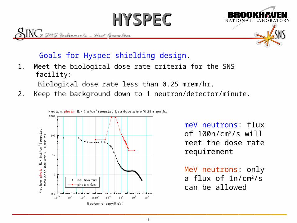
Goals for Hyspec shielding design.
1. Meet the biological dose rate criteria for the SNS facility:
Biological dose rate less than 0.25 mrem/hr.
2. Keep the background down to 1 neutron/detector/minute.
10-10 10-8 10-6 1x10⁻⁴ 10-2 100 102 1040.1
1
10
100
1000
Neutron, photon flux (n/s*cm2) required for a dose rate of 0.25 mrem/hr
Ne
utr
on
, ph
oto
n flu
x (n
/s*c
m2 )
req
uir
ed
fo
r a
do
se r
ate
of
0.2
5 m
rem
/hr
Neutron energy(MeV)
neutron fluxphoton flux
meV neutrons: flux of 100n/cm2/s will meet the dose rate requirement
MeV neutrons: only a flux of 1n/cm2/s can be allowed

6
HYSPECHYSPEC
E. Iverson’s simulation results for different SNS moderators
BL9 Water moderatorBL5 Cpl-H2BL2 Decoupled H2Generic average

7
HYSPECHYSPEC
10-9 10-6 10-3 100 103
0.0
0.2
0.4
0.6
0.8
1.0
He3 detector response function
Fra
ctio
n of
neu
tron
s ab
sorb
ed
Energy(MeV)
Absorption in He3 cell2.5cm thick, T = 300K
3atm. pressure 6atm. pressure
Shielding Goal #2.
Keep background down to 1 neutron per detector per minute.
Neutrons of low energies can be stopped easily in the drum shield
Neutrons with energy 1keV or more will not contribute to background.
High energy neutrons will moderate in the drum shield to produce neutrons that will add to background.
‘zhip’ zero hydrogen matrix for B4C?

8
HYSPECHYSPEC
T1A chopper
T1B chopper
Drum shield
Beam stop
9
HYSPECHYSPEC
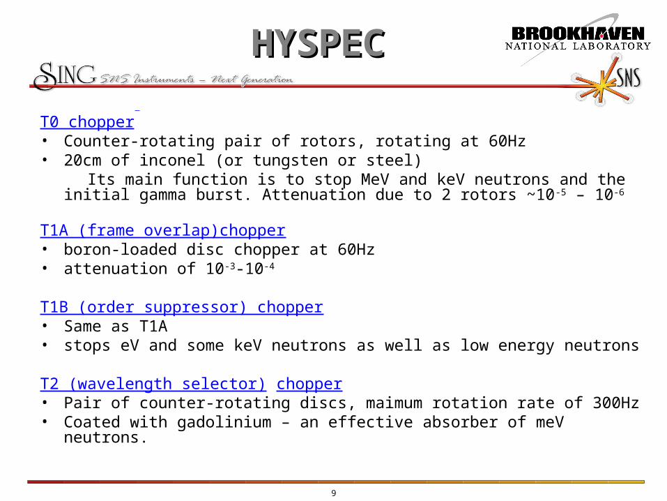
T0 chopper • Counter-rotating pair of rotors, rotating at 60Hz• 20cm of inconel (or tungsten or steel) Its main function is to stop MeV and keV neutrons and the initial gamma burst.
Attenuation due to 2 rotors ~10-5 – 10-6
T1A (frame overlap)chopper • boron-loaded disc chopper at 60Hz• attenuation of 10-3-10-4
T1B (order suppressor) chopper • Same as T1A• stops eV and some keV neutrons as well as low energy neutrons
T2 (wavelength selector) chopper • Pair of counter-rotating discs, maimum rotation rate of 300Hz• Coated with gadolinium – an effective absorber of meV neutrons.

10
HYSPECHYSPEC
Drum shield simulations
0 2 4 6 8 10 1210-5
10-4
10-3
Ratio of intensities for a shield thickness of 80cm
I(w
ith d
rum
shi
eld)
/I(w
ithou
t dr
um s
hiel
d)
thickness of material 2 (cm)
Material 1= borated poly5% boron by weightMaterial 2
stainless steel tungsten Steel_shot_mix
IR=0.2m OR=1.0m, height 1.5m, surface area=9m2 =105cm2

11
HYSPECHYSPEC
Hyspec shielding inside the target hall
1/R2 estimate for LMM=25m, straight 4cm(w) 12cm(h) guide, no choppers Total # of neutrons (all energies) at end of guide = 2.4x10¹⁰ n/s
MCNPX resultTotal # of neutrons (all energies) at end of guide = 1.2x10¹⁰ n/s = 7.2x10¹¹neutrons/minute.
If we want 1n/min/detector we need a total attenuation of 10-11 to 10-12
Attenuation due to T0 chopper ~ 10-5 – 10-6
Attenuation due to drum shield ~ 10-3 – 10-4
For isotropic (nonBragg) scattering by the monochromator neutron flux at drum shield face < 1n/cm2/s
Since scattering is not isotropic there may be a ‘hot spot’ in the line of sight of the moderator

12
HYSPECHYSPEC
Shielding outside the target hallLMM ~ 35-40m
Guide options1. 4cm wide straight2. 4cm wide, curved offset at mono. 16cm
Attenuation due to curvature ~10-6
This will allow us to make the Drum shield thinner

13
HYSPECHYSPEC
Comparison of instrument performance (monochromatic flux on sample and energy resolution) inside and outside the target hall.
20 25 30 35 40105
106
107
108
Energy 15meV Energy 60 meV
Mo
no
chro
ma
tic fl
ux
on
sa
mp
le(n
/cm
2 /s)
Moderator-monochromator distance (m)
Guide width 4cm, height 15cm3 theta-c supermirror coatingChopper slot width 4cmRotation rate 300 Hz
Ei(meV) LMM=25 LMM=35 LMM=40
3.6 2.2% 2.2% 2.1%
15 4.5% 4.3% 4.2%
30 6.4% 6.0% 5.9%
60 9.0% 8.2% 8.2%
90 10.4% 10.1% 9.8%
Energy resolution for moderator-monochromator distance LMM=25,35,40m

14
HYSPECHYSPEC
0 20 40 60 80 100105
106
107
Monochromatic flux on sample as a function of energy
Flu
x o
n (
2cm
x2cm
) sa
mp
le(n
/cm
2 /s)
Energy(meV)
MM distance 25mMM distance 35mMM distance 40m
coupled-H2 moderator
Ei(meV) LMM=25 LMM=35 LMM=40
3.6 7.2e6 5.2e6 4.7e6
15 8.0e6 5.9e6 5.3e6
30 2.9e6 2.0e6 1.7e6
60 1.1e6 8.2e6 7.1e6
90 1.1e6 10.1e6 6.6e5
Monochromatic flux on sample for LMM = 25,35, and 40m
Monochromatic flux on sample for some representative energies

15
HYSPECHYSPEC
1. Use a tapered guide that converges from 10 to 4 cm in the horizontal plane.
Does not look promising.
2. Increase the burst width at the sample
a. by slowing rotation rate of wavelength-defining (T2) chopper, or
b. by increasing the slot width of the T2 chopper.
60 120 180 240 300105
106
107
108
MM distance 40 mGuide width 4cm, straight3 theta-c supermirrorGuide reflectivity 98%Chopper slot width 4cm
Energy 15 meV Energy 60 meV
Mo
no
chro
ma
tic fl
ux
on
sa
mp
le(n
/cm
2 /s)
T2 chopper rotation rate (Hz)
Can we increase signal outside the target hall?

16
HYSPECHYSPEC
Energy resolution δE/E ~ 2 δt/tAs the burst width increases the energy resolution deterioratesEnergy resolution can be improved by increasing the sample-detector
distance from 4.5 to 6 or 7.5m.
150 180 210 240 270 300 3300
1
2
3
4
5
6
7
8
9
10L1 = 40m, E=15meV, T2 slot width 4cm
dE
/E (
%)
T2 Chopper rotation rate (Hz)
Fixed dE/E=4.5% Lsd = 4.5 m Lsd = 6.0 m Lsd = 7.5 m
LMM(m) T2 slot width
Lsd(m) T2 rotation rate(Hz)
Flux on sample (n/cm2/s)
25 4cm 4.5 300 8.0e6
40 4cm 4.5 300 5.3e6
40 4cm 6.0 240 6.5e6
40 4.5cm 6.0 240 7.0e6
40 4cm 7.5 180 8.7e6
Ei = 15meV
17
HYSPECHYSPEC
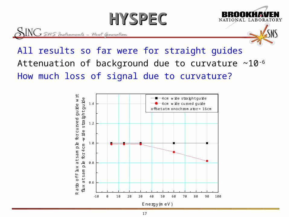
All results so far were for straight guides
Attenuation of background due to curvature ~10-6
How much loss of signal due to curvature?
-10 0 10 20 30 40 50 60 70 80 90 100
0.6
0.8
1.0
1.2
1.44cm wide straight guide4cm wide curved guide
offset at monochromator = 16cm
Rat
io o
f Flu
x at
sam
ple
for
curv
ed g
uide
wrt
flu
x at
sam
ple
for
4cm
-wid
e st
raig
ht g
uide
Energy(meV)

18
HYSPECHYSPEC
Comparison of instrument performance inside and
outside the target hall
Inside LMM=25m
Lsd=4.5m
Outside LMM=35-40
Lsd=4.5m
Outside LMM=35-40
Lsd=6.0m
Signal (15meV) 8.0e6 5.3e6 7.0e6
Energy resolution 4.5% 4.5% 4.5%
Shielding/background Difficult with straight guide
Much easier with curved guide
Much easier with curved guide
Advantages Shorter primary guide
Drum shield is simpler
Drum shield is simpler
Extra Cost Building Bldg + larger detector bank

19
HYSPECHYSPEC
Future plans
1. Shielding sims with BL5 source instead of generic source
Using BNL multinode computer cluster
Drum shield design
2. Instrument optimization
Guide configuration, coating
Chopper placement
Variable monochromator-sample distance
3. Q resolution

20
HYSPECHYSPEC
Questions?