Mold making with 3 to 5-axis simultaneous milling€¦ · SINUMERIK, Manual, Mold Making, 3 to...
128
SINUMERIK Milling with SINUMERIK Mold making with 3 to 5-axis simultaneous milling Manual
Transcript of Mold making with 3 to 5-axis simultaneous milling€¦ · SINUMERIK, Manual, Mold Making, 3 to...

SINUMERIK
Milling with SINUMERIK
Mold making with 3 to 5-axis simultaneous milling
Manual

Milling with SINUMERIKMold making with 3 to 5-axis simultaneous milling
Manual
Valid for:
Control system
SINUMERIK 828DSINUMERIK 840D sl
Edition 09/2011Document Order No. 6FC5095-0AB10-0BP2
Basic information 1General information onworkpiece production 2Important functions for5-axis machining 3
Aerospace, structural parts 4Driving gear and turbinecomponents 5
Complex free-form surfaces 6
Example workpiece 7
Reference section 8
IntroductionPrinting history, registered trademarks0
4
0 Introduction
SINUMERIK® documentationPrinting history, registered trademarksBrief details of this edition and previous editions are listed below.The status of each edition is shown by the code in the "Remarks" column.
Status code in the "Remarks" column:
A .... New documentationB .... Unrevised reprint with new order numberC .... Revised version with new edition status
Registered TrademarksSIMATIC, SIMATIC HMI, SIMATIC NET, SIROTEC, SINUMERIK, SIMODRIVE and SINAMICS are registered trademarks of Siemens AG. Other names in this publication may be trademarks whose use by third parties for their own purposes could violate the rights of the owner.
Output Order No. Remarks
09.2011 6FC5095-0AB10-0BP2 C
05.2009 6FC5095-0AB10-0BP1 A
More information is available on the Internet at:http://www.siemens.com/sinumerik
This document was created using a number of layout and graphic tools.The reproduction, transmission or use of this document or its contents is not permitted without express written authority. Offenders will be liable for damages. All rights, including rights created by patent grant or registration of a utility or design, are reserved.
© Siemens AG 1995 - 2011. All rights reserved.
Other functions not described in this documentation might be executable in the control. This does not, however, represent an obligation to supply such functions with a new control or when servicing.
We have verified that the contents of this document corre-spond to the hardware and software described. However, since deviations cannot be precluded entirely, we cannot guarantee full consistency. Nevertheless, the information con-tained in this document is reviewed regularly and any neces-sary changes will be included in subsequent editions. Suggestions for improvement are welcome.
Technical data subject to change.
Order No. 6FC5095-0AB10-0BP2 Siemens AG
© Siemens AG All rights reserved. SINUMERIK, Manual, Mold Making, 3 to 5-Axis Simultaneous Milling
IntroductionContent 0
0 Introduction Content
Page1 Basic information ................................................................................................................ 7
1.1 Introduction ..................................................................................................................8
1.2 SINUMERIK MDynamics milling technology packages ...............................................9
1.3 SINUMERIK Operate user interface ..........................................................................10
1.4 Requirements for milling ............................................................................................11
1.5 Linear axes, rotary axes and kinematics ...................................................................12
1.6 Surface quality, speed, accuracy ..............................................................................15
2 General information on workpiece production................................................................ 17
2.1 Process chain for producing 3 to 5-axis workpieces .................................................18
2.2 CAD systems .............................................................................................................19
2.3 Program structure for milling .....................................................................................21
2.4 Program storage/data transfer ..................................................................................23
2.5 Work offsets ..............................................................................................................25
2.6 Tool management .....................................................................................................26
2.7 Measuring in JOG and AUTOMATIC ........................................................................27
2.8 Workpiece measuring in JOG ...................................................................................28
2.9 Measure tool in JOG .................................................................................................30
2.10 Workpiece measuring in AUTOMATIC - process measuring ....................................33
2.11 Tool measuring in AUTOMATIC - process measuring ..............................................35
2.12 Checking/measuring the machine with the kinematics measuring cycleCYCLE996 ...............................................................................................................37
2.13 Workpiece visualization .............................................................................................39
3 Important functions 3 to 5-axis machining ...................................................................... 41
3.1 Introduction ................................................................................................................42
3.2 Explanation of the terms swivel, frames and TRAORI ..............................................43
3.3 Transforming coordinate systems - Frames ..............................................................44
3.4 Swivel - CYCLE800 ...................................................................................................45
3.5 TRAORI 5-axis transformation ..................................................................................51
3.6 High Speed Settings - CYCLE832 Advanced Surface ..............................................66
3.7 Advanced Surface - NC commands ..........................................................................69
3.8 3D tool radius compensations ...................................................................................79
3.9 Volumetric compensation system (VCS) ...................................................................82
3.10 VNCK - Virtual machine ............................................................................................83
4 Aerospace, structural parts .............................................................................................. 85
4.1 Special functions for structural parts .........................................................................86
4.2 Programming example for the pocket on a structural part ........................................87
© Siemens AG All rights reserved. SINUMERIK, Manual, Mold Making, 3 to 5-Axis Simultaneous Milling
5
IntroductionContent0
6
Page5 Driving gear and turbine components ............................................................................. 91
5.1 Special functions for driving gear and turbine components ...................................... 92
5.2 Example: Turbine blade ............................................................................................ 93
6 Complex free-form surfaces.............................................................................................. 97
6.1 Special functions for free-form surfaces .................................................................... 98
6.2 Example: Milling a manta ray .................................................................................... 99
7 Example workpiece .......................................................................................................... 103
7.1 Example workpiece milled from 3 to 3+2-axis ......................................................... 104
7.2 Example with 3-axis milled ...................................................................................... 106
7.3 Example with 3+1-axis milled .................................................................................. 107
7.4 Example with 3+2-axis milled .................................................................................. 108
7.5 Comparison of the three variants ............................................................................ 109
8 Reference section ........................................................................................................... 111
8.1 Overview of higher-order functions ......................................................................... 112
8.2 Further information/documentation ......................................................................... 122
8.3 Index ....................................................................................................................... 124
© Siemens AG All rights reserved. SINUMERIK, Manual, Mold Making, 3 to 5-Axis Simultaneous Milling
Basic information
Content Page1.1 Introduction 81.2 SINUMERIK MDynamics milling technology packages 91.3 SINUMERIK Operate user interface 101.4 Requirements for milling 111.5 Linear axes, rotary axes and kinematics 121.6 Surface quality, speed, accuracy 15
Basic information1.1
8
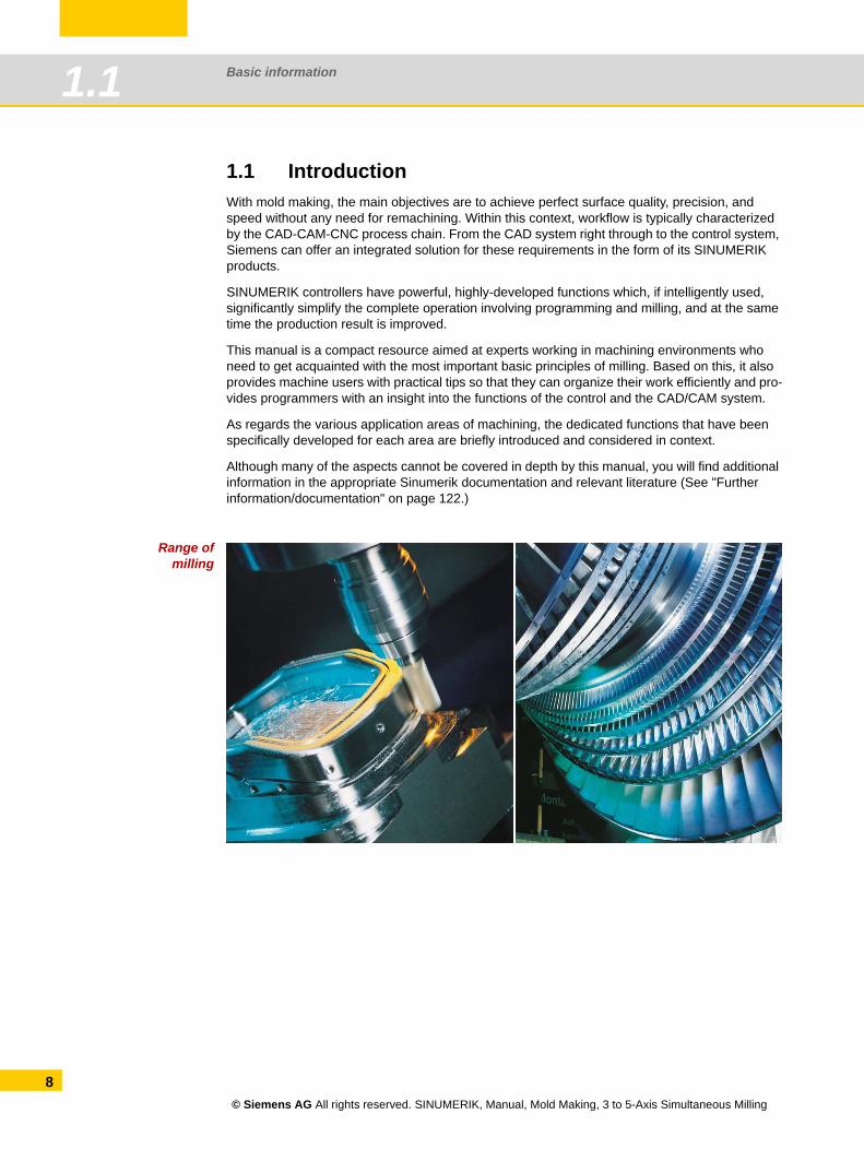
1.1 IntroductionWith mold making, the main objectives are to achieve perfect surface quality, precision, and speed without any need for remachining. Within this context, workflow is typically characterized by the CAD-CAM-CNC process chain. From the CAD system right through to the control system, Siemens can offer an integrated solution for these requirements in the form of its SINUMERIK products.
SINUMERIK controllers have powerful, highly-developed functions which, if intelligently used, significantly simplify the complete operation involving programming and milling, and at the same time the production result is improved.
This manual is a compact resource aimed at experts working in machining environments who need to get acquainted with the most important basic principles of milling. Based on this, it also provides machine users with practical tips so that they can organize their work efficiently and pro-vides programmers with an insight into the functions of the control and the CAD/CAM system.
As regards the various application areas of machining, the dedicated functions that have been specifically developed for each area are briefly introduced and considered in context.
Although many of the aspects cannot be covered in depth by this manual, you will find additional information in the appropriate Sinumerik documentation and relevant literature (See "Further information/documentation" on page 122.)
Range ofmilling
© Siemens AG All rights reserved. SINUMERIK, Manual, Mold Making, 3 to 5-Axis Simultaneous Milling
Basic information 1.2
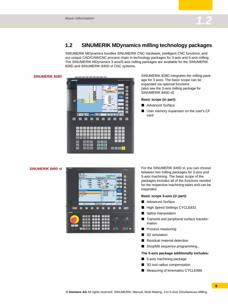
1.2 SINUMERIK MDynamics milling technology packagesSINUMERIK MDynamics bundles SINUMERIK CNC hardware, intelligent CNC functions, and our unique CAD/CAM/CNC process chain in technology packages for 3-axis and 5-axis milling. The SINUMERIK MDynamics 3-axis/5-axis milling packages are available for the SINUMERIK 828D and SINUMERIK 840D sl CNC systems.
SINUMERIK 828D
SINUMERIK 840D sl
SINUMERIK 828D integrates the milling pack-age for 3 axes. The basic scope can be expanded via optional functions (also see the 3-axis milling package forSINUMERIK 840D sl)
Basic scope (in part):Advanced Surface
User memory expansion on the user's CF card
For the SINUMERIK 840D sl, you can choose between two milling packages for 3-axis and 5-axis machining. The basic scope of the packages includes all of the functions needed for the respective machining tasks and can be expanded.
Basic scope 3-axis (in part):Advanced Surface
High Speed Settings CYCLE832
Spline interpolation
Transmit and peripheral surface transfor-mation
Process measuring
3D simulation
Residual material detection
ShopMill sequence programming...
The 5-axis package additionally includes:5-axis machining package
3D tool radius compensation
Measuring of kinematics CYCLE996
© Siemens AG All rights reserved. SINUMERIK, Manual, Mold Making, 3 to 5-Axis Simultaneous Milling
9
Basic information1.3
10
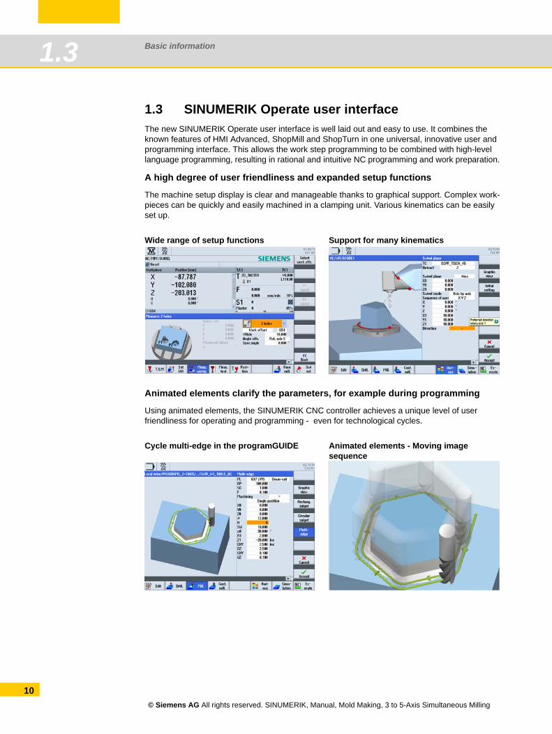
1.3 SINUMERIK Operate user interfaceThe new SINUMERIK Operate user interface is well laid out and easy to use. It combines the known features of HMI Advanced, ShopMill and ShopTurn in one universal, innovative user and programming interface. This allows the work step programming to be combined with high-level language programming, resulting in rational and intuitive NC programming and work preparation.
A high degree of user friendliness and expanded setup functions
The machine setup display is clear and manageable thanks to graphical support. Complex work-pieces can be quickly and easily machined in a clamping unit. Various kinematics can be easily set up.
Animated elements clarify the parameters, for example during programming
Using animated elements, the SINUMERIK CNC controller achieves a unique level of user friendliness for operating and programming - even for technological cycles.
Wide range of setup functions Support for many kinematics
Cycle multi-edge in the programGUIDE Animated elements - Moving image sequence
© Siemens AG All rights reserved. SINUMERIK, Manual, Mold Making, 3 to 5-Axis Simultaneous Milling
Basic information 1.4
1.4 Requirements for milling
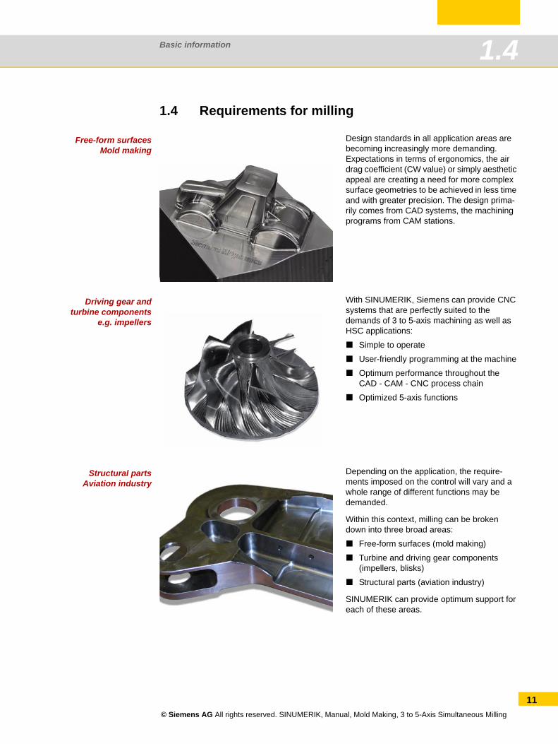
Free-form surfacesMold making
Driving gear andturbine components
e.g. impellers
Structural partsAviation industry
Design standards in all application areas are becoming increasingly more demanding.Expectations in terms of ergonomics, the air drag coefficient (CW value) or simply aesthetic appeal are creating a need for more complex surface geometries to be achieved in less time and with greater precision. The design prima-rily comes from CAD systems, the machining programs from CAM stations.
With SINUMERIK, Siemens can provide CNC systems that are perfectly suited to the demands of 3 to 5-axis machining as well as HSC applications:
Simple to operate
User-friendly programming at the machine
Optimum performance throughout the CAD - CAM - CNC process chain
Optimized 5-axis functions
Depending on the application, the require-ments imposed on the control will vary and a whole range of different functions may be demanded.
Within this context, milling can be broken down into three broad areas:
Free-form surfaces (mold making)
Turbine and driving gear components (impellers, blisks)
Structural parts (aviation industry)
SINUMERIK can provide optimum support for each of these areas.
© Siemens AG All rights reserved. SINUMERIK, Manual, Mold Making, 3 to 5-Axis Simultaneous Milling
11
Basic information1.5
12
1.5 Linear axes, rotary axes and kinematics
1.5.1 Axes and programming
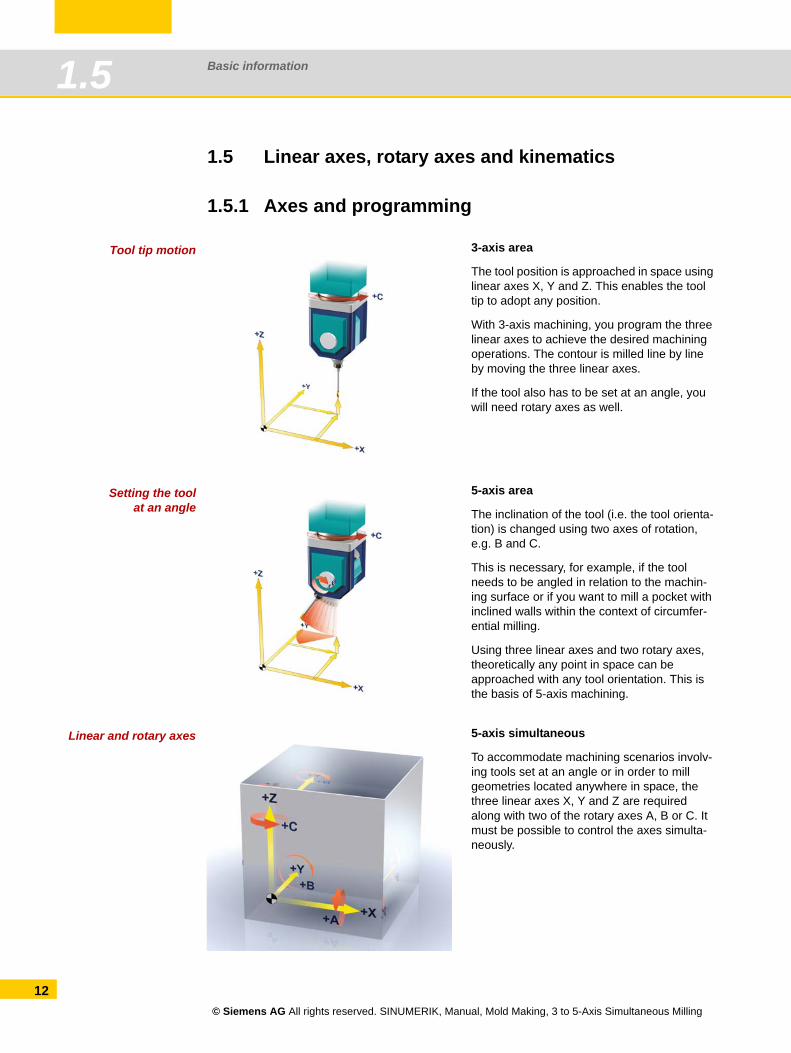
Tool tip motion
Setting the toolat an angle
Linear and rotary axes
3-axis area
The tool position is approached in space using linear axes X, Y and Z. This enables the tool tip to adopt any position.
With 3-axis machining, you program the three linear axes to achieve the desired machining operations. The contour is milled line by line by moving the three linear axes.
If the tool also has to be set at an angle, you will need rotary axes as well.
5-axis area
The inclination of the tool (i.e. the tool orienta-tion) is changed using two axes of rotation, e.g. B and C.
This is necessary, for example, if the tool needs to be angled in relation to the machin-ing surface or if you want to mill a pocket with inclined walls within the context of circumfer-ential milling.
Using three linear axes and two rotary axes, theoretically any point in space can be approached with any tool orientation. This is the basis of 5-axis machining.
5-axis simultaneous
To accommodate machining scenarios involv-ing tools set at an angle or in order to mill geometries located anywhere in space, the three linear axes X, Y and Z are required along with two of the rotary axes A, B or C. It must be possible to control the axes simulta-neously.
© Siemens AG All rights reserved. SINUMERIK, Manual, Mold Making, 3 to 5-Axis Simultaneous Milling
Basic information 1.5
CNC programming options in the 5-axis area
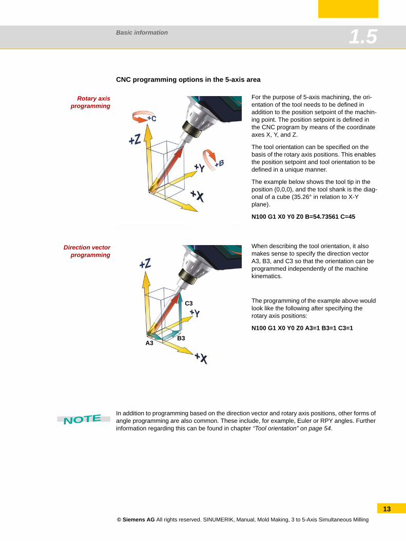
Rotary axisprogramming
Direction vectorprogramming
In addition to programming based on the direction vector and rotary axis positions, other forms of angle programming are also common. These include, for example, Euler or RPY angles. Further information regarding this can be found in chapter “Tool orientation” on page 54.
For the purpose of 5-axis machining, the ori-entation of the tool needs to be defined in addition to the position setpoint of the machin-ing point. The position setpoint is defined in the CNC program by means of the coordinate axes X, Y, and Z.
The tool orientation can be specified on the basis of the rotary axis positions. This enables the position setpoint and tool orientation to be defined in a unique manner.
The example below shows the tool tip in the position (0,0,0), and the tool shank is the diag-onal of a cube (35.26° in relation to X-Y plane).
N100 G1 X0 Y0 Z0 B=54.73561 C=45
When describing the tool orientation, it also makes sense to specify the direction vector A3, B3, and C3 so that the orientation can be programmed independently of the machine kinematics.
The programming of the example above would look like the following after specifying the rotary axis positions:
N100 G1 X0 Y0 Z0 A3=1 B3=1 C3=1
C3
B3A3
NOTE
© Siemens AG All rights reserved. SINUMERIK, Manual, Mold Making, 3 to 5-Axis Simultaneous Milling
13
Basic information1.5
14
1.5.2 Kinematics of 5-axis machining centersA 5-axis machine can control tool motion in 5 axes. These are the three linear axes (with which you will already be familiar) and an additional two rotary axes. There are different kinematic solu-tions for the two rotary axes. We will present the most common of these schematically. With SINUMERIK controls, even special kinematics can be controlled on the basis of the integrated, kinematic transformation feature. Special cases such as hexapods, etc. will not be explored in further detail here.
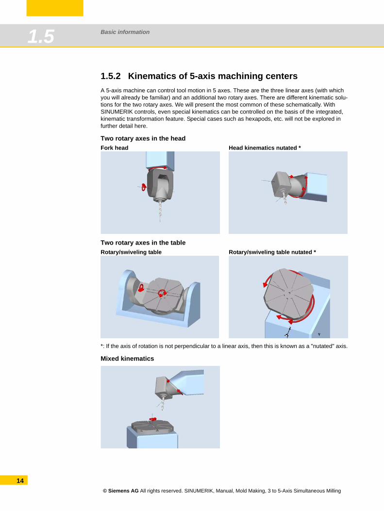
Two rotary axes in the head
Two rotary axes in the table
*: If the axis of rotation is not perpendicular to a linear axis, then this is known as a "nutated" axis.
Mixed kinematics
Fork head Head kinematics nutated *
Rotary/swiveling table Rotary/swiveling table nutated *
© Siemens AG All rights reserved. SINUMERIK, Manual, Mold Making, 3 to 5-Axis Simultaneous Milling
Basic information 1.6
1.6 Surface quality, speed, accuracySpecial attention must be paid to the CAD -> CAM -> (post processor) -> CNC process chain when machining three-dimensional geometries, e.g. free-form surfaces. CAM systems generate NC programs for free-form surface machining. The CAM system receives the workpiece geome-try from a CAD system. The CNC machine has to process the NC data generated and convert it into axis movements.
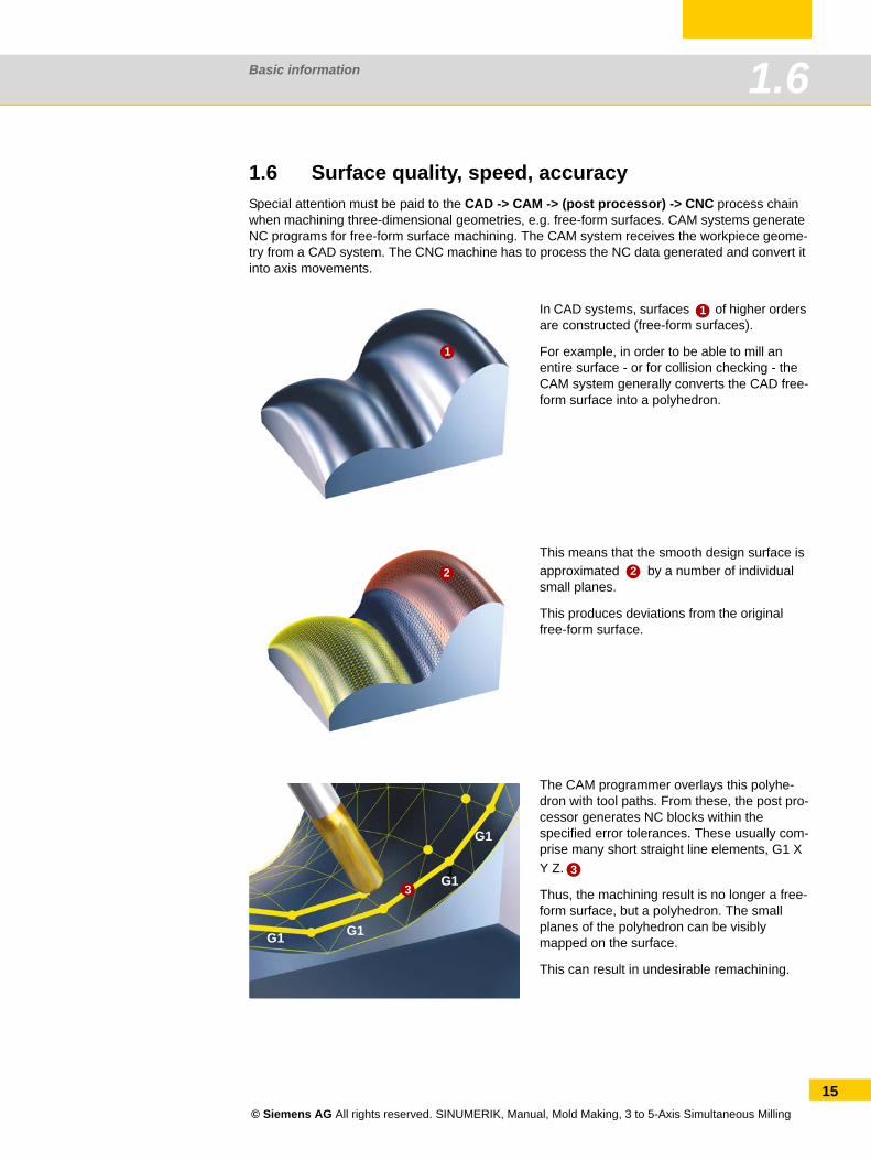
In CAD systems, surfaces of higher orders are constructed (free-form surfaces).
For example, in order to be able to mill an entire surface - or for collision checking - the CAM system generally converts the CAD free-form surface into a polyhedron.
This means that the smooth design surface is approximated by a number of individual small planes.
This produces deviations from the original free-form surface.
The CAM programmer overlays this polyhe-dron with tool paths. From these, the post pro-cessor generates NC blocks within the specified error tolerances. These usually com-prise many short straight line elements, G1 X Y Z.
Thus, the machining result is no longer a free-form surface, but a polyhedron. The small planes of the polyhedron can be visibly mapped on the surface.
This can result in undesirable remachining.
1
1
2 2
31
G1
G1
G1G1
3
© Siemens AG All rights reserved. SINUMERIK, Manual, Mold Making, 3 to 5-Axis Simultaneous Milling
15
Basic information1.6
16
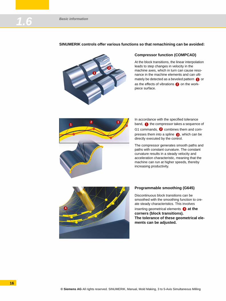
SINUMERIK controls offer various functions so that remachining can be avoided:
Compressor function (COMPCAD)
At the block transitions, the linear interpolation leads to step changes in velocity in the machine axes, which in turn can cause reso-nance in the machine elements and can ulti-mately be detected as a beveled pattern or as the effects of vibrations on the work-piece surface.
In accordance with the specified tolerance band, the compressor takes a sequence of G1 commands, combines them and com-presses them into a spline , which can be directly executed by the control.
The compressor generates smooth paths and paths with constant curvature. The constant curvature results in a steady velocity and acceleration characteristic, meaning that the machine can run at higher speeds, thereby increasing productivity.
Programmable smoothing (G645)
Discontinuous block transitions can be smoothed with the smoothing function to cre-ate steady characteristics. This involves inserting geometrical elements at the corners (block transitions). The tolerance of these geometrical ele-ments can be adjusted.
12
12
12 3 1
2
3
4 4
© Siemens AG All rights reserved. SINUMERIK, Manual, Mold Making, 3 to 5-Axis Simultaneous Milling
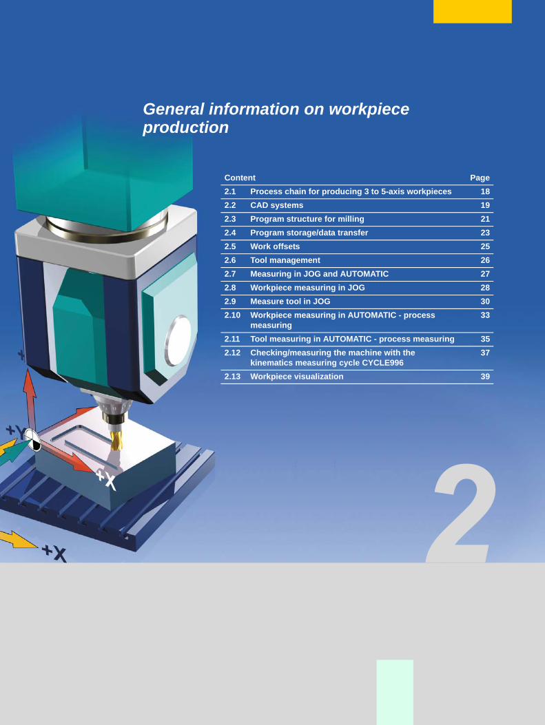
General information on workpieceproduction
Content Page2.1 Process chain for producing 3 to 5-axis workpieces 182.2 CAD systems 192.3 Program structure for milling 212.4 Program storage/data transfer 232.5 Work offsets 252.6 Tool management 262.7 Measuring in JOG and AUTOMATIC 272.8 Workpiece measuring in JOG 282.9 Measure tool in JOG 302.10 Workpiece measuring in AUTOMATIC - process
measuring33
2.11 Tool measuring in AUTOMATIC - process measuring 352.12 Checking/measuring the machine with the
kinematics measuring cycle CYCLE99637
2.13 Workpiece visualization 39
General information on workpiece production2.1
18
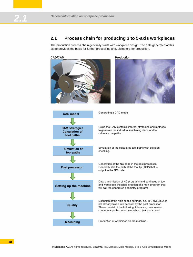
2.1 Process chain for producing 3 to 5-axis workpiecesThe production process chain generally starts with workpiece design. The data generated at this stage provides the basis for further processing and, ultimately, for production.
CAD/CAM Production
CAD model
CAM strategiesCalculation of
tool paths
Simulation oftool paths
Post processor
Setting up the machine
Quality
Machining
Generating a CAD model
Using the CAM system's internal strategies and methods to generate the individual machining steps and to calculate the paths.
Simulation of the calculated tool paths with collision checking.
Generation of the NC code in the post processor. Generally, it is the path at the tool tip (TCP) that is output in the NC code.
Data transmission of NC programs and setting up of tool and workpiece. Possible creation of a main program that will call the generated geometry programs.
Definition of the high speed settings, e.g. in CYCLE832, if not already taken into account by the post processor. These consist of the following: tolerance, compressor, continuous-path control, smoothing, jerk and speed.
Production of workpiece on the machine.
© Siemens AG All rights reserved. SINUMERIK, Manual, Mold Making, 3 to 5-Axis Simultaneous Milling
General information on workpiece production 2.2
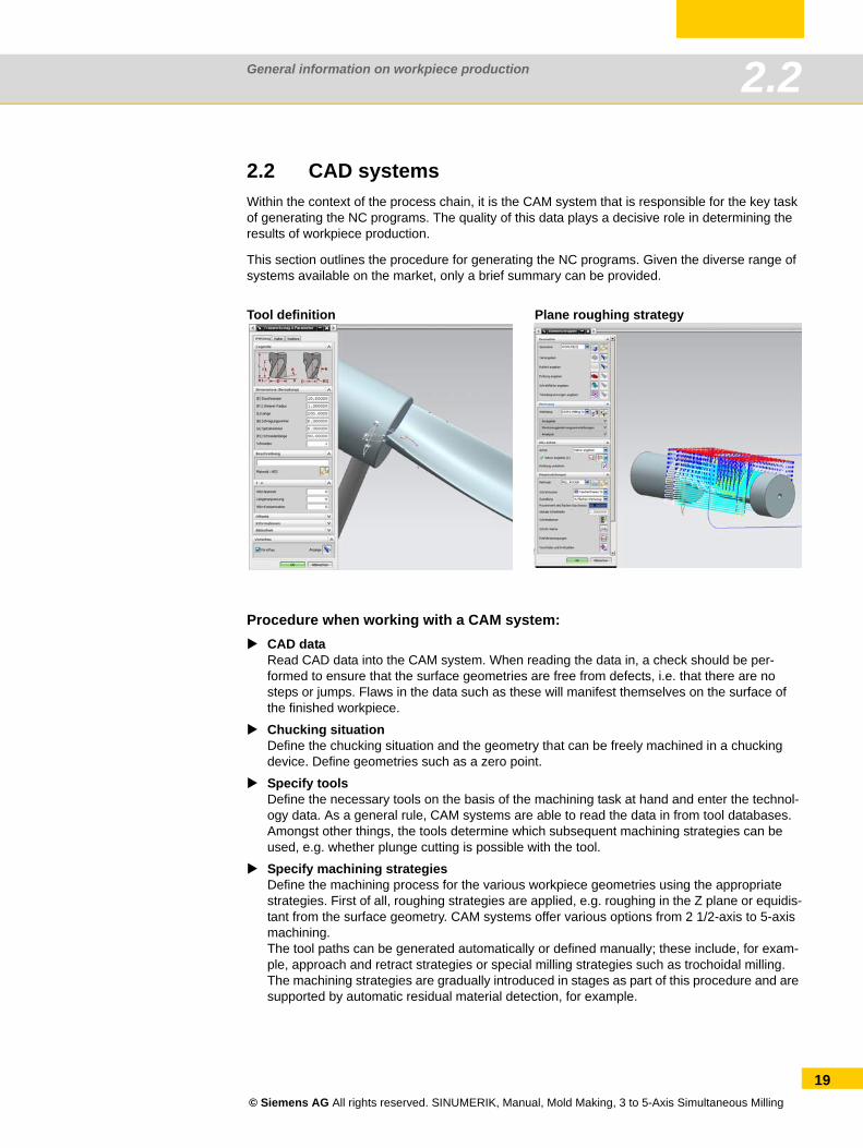
2.2 CAD systemsWithin the context of the process chain, it is the CAM system that is responsible for the key task of generating the NC programs. The quality of this data plays a decisive role in determining the results of workpiece production.
This section outlines the procedure for generating the NC programs. Given the diverse range of systems available on the market, only a brief summary can be provided.
Procedure when working with a CAM system:CAD dataRead CAD data into the CAM system. When reading the data in, a check should be per-formed to ensure that the surface geometries are free from defects, i.e. that there are no steps or jumps. Flaws in the data such as these will manifest themselves on the surface of the finished workpiece.
Chucking situationDefine the chucking situation and the geometry that can be freely machined in a chucking device. Define geometries such as a zero point.
Specify toolsDefine the necessary tools on the basis of the machining task at hand and enter the technol-ogy data. As a general rule, CAM systems are able to read the data in from tool databases. Amongst other things, the tools determine which subsequent machining strategies can be used, e.g. whether plunge cutting is possible with the tool.
Specify machining strategiesDefine the machining process for the various workpiece geometries using the appropriate strategies. First of all, roughing strategies are applied, e.g. roughing in the Z plane or equidis-tant from the surface geometry. CAM systems offer various options from 2 1/2-axis to 5-axis machining.The tool paths can be generated automatically or defined manually; these include, for exam-ple, approach and retract strategies or special milling strategies such as trochoidal milling. The machining strategies are gradually introduced in stages as part of this procedure and are supported by automatic residual material detection, for example.
Tool definition Plane roughing strategy
© Siemens AG All rights reserved. SINUMERIK, Manual, Mold Making, 3 to 5-Axis Simultaneous Milling
19
General information on workpiece production2.2
20
Calculation and simulationWhen simulating the calculated tool paths/machine movements, different levels of quality can be used, from straightforward simulation of the tool paths through to complete simulation of the G and M codes that takes account of all machine-specific and control-specific data. Here, potential collisions can be detected and avoided, for example, and the machine's maximum axis traversing ranges can be taken into account.
Output of the NC code with the post processorThe post processor converts the sequences into NC programs taking into account the con-trol-specific syntax and the control's special functions. For this purpose, CAM systems make use of universal post processors or special post processors that have been optimized for the SINUMERIK system. Manufacturer-specific functions such as separate coolant strategies must be implemented in the post processor in consultation with the machine manufacturer.
Important parameters
When working with CAD/CAM systems, certain tolerances and levels of accuracy that will have an impact on subsequent machining must be observed.
Tolerance The CAM system uses the CAD surface (spline) to generate a contour consisting of linear tra-versing blocks (straight line elements). The extent to which the linear contour deviates from the real contour from the CAD system is known as the chord error or chord tolerance. This tolerance depends on the strategy used and is greater in the case of roughing strategies than with finishing strategies. When the NC programs are executed on the machine, the tolerance is specified by the CAM system in CYCLE832 so that optimum results can be achieved in terms of surface qual-ity and contour accuracy.
Accuracy When outputting the NC blocks from the CAM system, you can specify the number of decimal places. The required level of accuracy is dependent on the type of interpolation. In the case of linear axes (X, Y, Z), at least 3 decimal places should be used for 3-axis programs.
If the blocks are to be output as rotary axis positions, with 5-axis programs 5 decimal commas should be used in the linear and rotary axes for optimum surface quality. If they are to be output in the form of a direction vector, we recommend 5 decimal places in the linear axes and at least 6 decimal places for the direction vectors.
© Siemens AG All rights reserved. SINUMERIK, Manual, Mold Making, 3 to 5-Axis Simultaneous Milling
General information on workpiece production 2.3
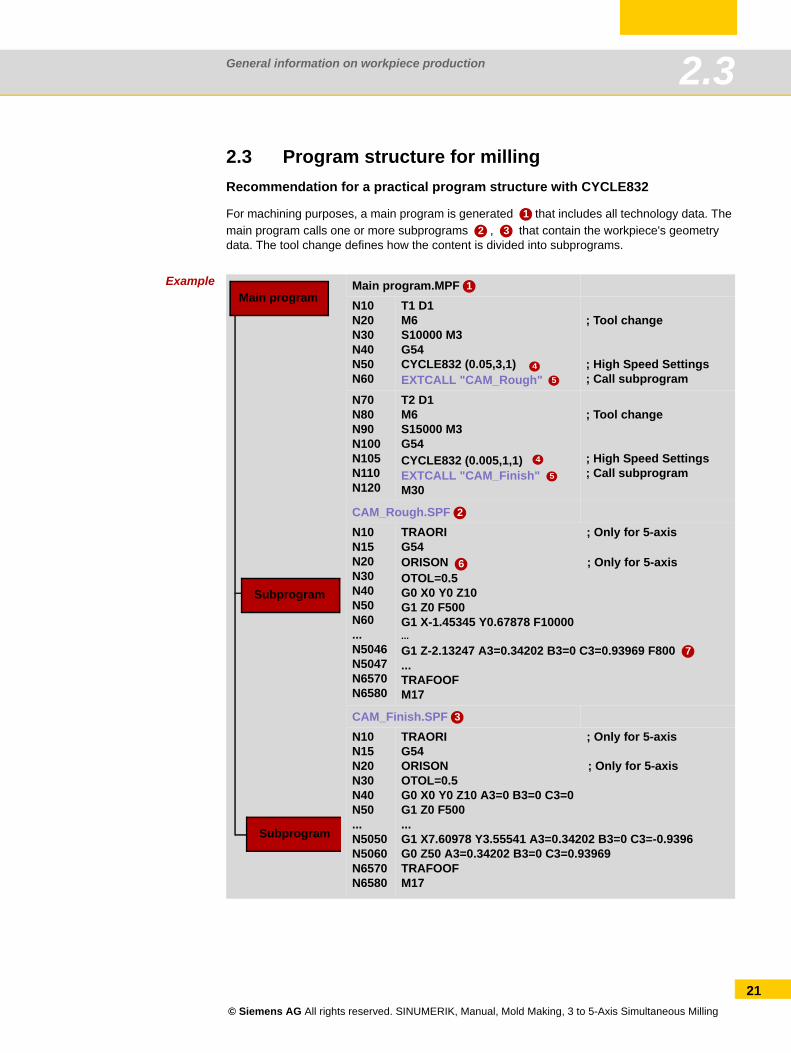
2.3 Program structure for millingRecommendation for a practical program structure with CYCLE832
For machining purposes, a main program is generated that includes all technology data. The main program calls one or more subprograms , that contain the workpiece's geometry data. The tool change defines how the content is divided into subprograms.
Example
12 3
Main program.MPFN10N20N30N40N50N60
T1 D1M6 S10000 M3G54CYCLE832 (0.05,3,1) EXTCALL "CAM_Rough"
; Tool change
; High Speed Settings; Call subprogram
N70N80N90N100N105N110N120
T2 D1M6S15000 M3G54CYCLE832 (0.005,1,1) EXTCALL "CAM_Finish" M30
; Tool change
; High Speed Settings; Call subprogram
CAM_Rough.SPFN10N15N20N30N40N50N60...N5046N5047N6570N6580
TRAORI ; Only for 5-axisG54ORISON ; Only for 5-axisOTOL=0.5G0 X0 Y0 Z10G1 Z0 F500G1 X-1.45345 Y0.67878 F10000...G1 Z-2.13247 A3=0.34202 B3=0 C3=0.93969 F800 ...TRAFOOFM17
CAM_Finish.SPFN10N15N20N30N40N50...N5050N5060N6570N6580
TRAORI ; Only for 5-axisG54ORISON ; Only for 5-axisOTOL=0.5G0 X0 Y0 Z10 A3=0 B3=0 C3=0G1 Z0 F500...G1 X7.60978 Y3.55541 A3=0.34202 B3=0 C3=-0.9396 G0 Z50 A3=0.34202 B3=0 C3=0.93969TRAFOOFM17
Main program
Subprogram
Subprogram
1
4
5
4
5
2
6
7
3
© Siemens AG All rights reserved. SINUMERIK, Manual, Mold Making, 3 to 5-Axis Simultaneous Milling
21
General information on workpiece production2.3
22
Main program: The main program includes the two key functions for milling, CYCLE832 and EXTCALL .
CYCLE832 : CYCLE832 was specifically adapted for the program structure shown, where technology data and geometry data are separated. It brings together all the key commands and activates control functions. The machining technology for milling is defined in CYCLE832. For the roughing program "CAM_Rough" using T1, the parameters in CYCLE832 were geared towards achieving a high velocity. For the finishing program "CAM_Finish", the parameters were geared toward achieving a high level of surface quality and accuracy.TRAORI is needed for multi-axis transformation. For more information about CYCLE832, see chapter See "High Speed Settings - CYCLE832 Advanced Surface" on page 66.
EXTCALL : CAM programs are generally extremely large, which is why they are stored in an external memory. The EXTCALL command is used to call the subprograms from various loca-tions, including external memories. All programs should be located in the same directory. If this is not the case, the paths must also be specified during the call.
ORISON/OTOL : The NC command ORISON is a vector smoothing function that has been specially developed for the 5-axis area. This function can be used to smooth fluctuating orienta-tion across several blocks. The aim is to achieve a smooth characteristic for the orientation and a more harmonious movement of the axes. Since this command is not part of CYCLE832, it is rec-ommended that ORISON be programmed after CYCLE832.
The OTOL command can be used to define the orientation tolerance for vector smoothing with ORISON. The value is entered in degrees. The value recommended here is 0.5 degrees.
Subprogram: In the subprogram, ORISON programming is immediately followed by the geome-try blocks. In our example, these initially take the form of blocks for 3-axis milling, which are then followed by the blocks for 5-axis simultaneous milling. These are designated A3, B3, and C3.
45
4
5
6
7
© Siemens AG All rights reserved. SINUMERIK, Manual, Mold Making, 3 to 5-Axis Simultaneous Milling
General information on workpiece production 2.4
2.4 Program storage/data transfer
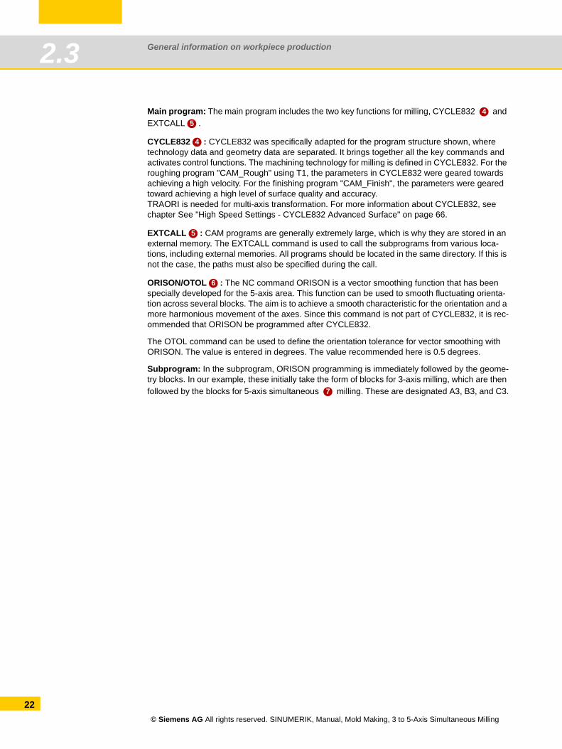
2.4.1 Program managerThe program manager offers you an optimum overview of the directories and programs, and very easy-to-use file handling. It supports plain text names of up to 24 characters for directories and files. For the SINUMERIK 828D and on the NC, subdirectories can also be managed on external storage media such as CF cards and USB flash drives.
All storage media including the network drives are displayed in the program manager. The part programs can be edited in all media. You can create, paste, copy, delete and cut programs via the horizontal softkey bar.
In the program manager, you can use standard Windows short-cuts such as CTRL+C, CTRL+X, and CTRL+V.
Possible storage locations for programs are:1. NC
2. Local drive (CompactFlash card or hard drive)
3. USB drives
4. Network drives
NOTE
1 2 3 4
© Siemens AG All rights reserved. SINUMERIK, Manual, Mold Making, 3 to 5-Axis Simultaneous Milling
23
General information on workpiece production2.4
24
2.4.2 External storage media - data transferNC programs are stored in the control, if required, downloaded into the NCK working memory (RAM), and executed on the machine.
Mold-making programs are often too large for the NC memory or they cannot be processed. Therefore these are swapped to an external memory and processed successively. In the main program, an EXTCALL command is programmed, which calls up the swapped-out program according to the network path on the server, the USB port, hard drive, etc.
Procedure when calling the geometry program using EXTCALLProgram the geometry program call, e.g. SAMPLE in the main program. The call differs depending on the control and where the data is saved.
The subprogram is located on the hard drive (NC) EXTCALL "SAMPLE"
The subprogram is located in the directory on the CompactFlash card EXTCALL "CF_CARD:/PROGRAMS/SAMPLE.SPF"
The subprogram is located on a local hard driveEXTCALL "LOCAL_DRIVE:/PROGRAMS/SAMPLE.SPF"
The subprogram is located on a USB flash driveEXTCALL "USB:/MOLD_DIE/CAM_SCHRUPP.SPF"
Network connected with Ethernet and path in the machine data SD 42700, e.g. on a server "//R4711/workpieces/subprograms". The default setting is optional. The directory can first be specified when making the call with EXTCALL.EXTCALL "SAMPLE.SPF"
Processing of USB flash drive/CF card
On the controller there is a USB port on the front, and on the SINUMERIK 828D there is a USB port on the front side and on the rear side. On the SINUMERIK 828D, there is a CompactFlash card slot on the front. On the SINUMERIK 840D sl, it is located on the rear side.
Storage media can be inserted or removed during operation, i.e. the machine does not have to be restarted in order for the storage medium to be recognized
Loading, editing and executing of part programs from the storage medium.
When executing part programs from a storage medium there is no loss of speed (DNC opera-tion), in which case executing from a CF card is recommended.
No special software is necessary for reading from or writing to the storage medium on the PC.
Direct execution from a USB flash drive is not recommended. Disconnecting during oper-ation will stop machining and, under certain circumstances, cause damage to the work-piece.
NOTE
© Siemens AG All rights reserved. SINUMERIK, Manual, Mold Making, 3 to 5-Axis Simultaneous Milling
General information on workpiece production 2.5
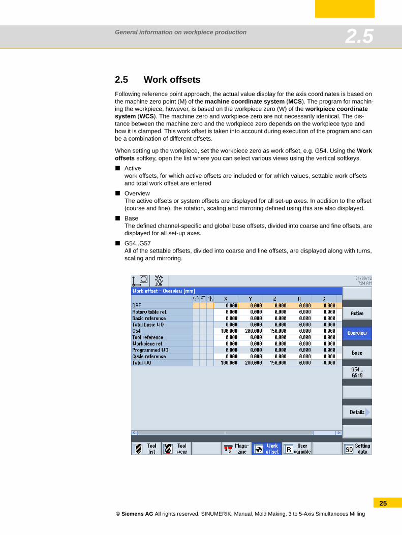
2.5 Work offsetsFollowing reference point approach, the actual value display for the axis coordinates is based on the machine zero point (M) of the machine coordinate system (MCS). The program for machin-ing the workpiece, however, is based on the workpiece zero (W) of the workpiece coordinate system (WCS). The machine zero and workpiece zero are not necessarily identical. The dis-tance between the machine zero and the workpiece zero depends on the workpiece type and how it is clamped. This work offset is taken into account during execution of the program and can be a combination of different offsets.
When setting up the workpiece, set the workpiece zero as work offset, e.g. G54. Using the Work offsets softkey, open the list where you can select various views using the vertical softkeys.
Activework offsets, for which active offsets are included or for which values, settable work offsets and total work offset are entered
OverviewThe active offsets or system offsets are displayed for all set-up axes. In addition to the offset (course and fine), the rotation, scaling and mirroring defined using this are also displayed.
BaseThe defined channel-specific and global base offsets, divided into coarse and fine offsets, are displayed for all set-up axes.
G54..G57All of the settable offsets, divided into coarse and fine offsets, are displayed along with turns, scaling and mirroring.
© Siemens AG All rights reserved. SINUMERIK, Manual, Mold Making, 3 to 5-Axis Simultaneous Milling
25
General information on workpiece production2.6
26
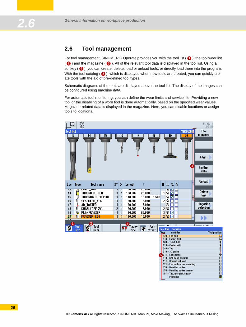
2.6 Tool managementFor tool management, SINUMERIK Operate provides you with the tool list ( ), the tool wear list ( ) and the magazine ( ). All of the relevant tool data is displayed in the tool list. Using a softkey ( ), you can create, delete, load or unload tools, or directly load them into the program. With the tool catalog ( ), which is displayed when new tools are created, you can quickly cre-ate tools with the aid of pre-defined tool types.
Schematic diagrams of the tools are displayed above the tool list. The display of the images can be configured using machine data.
For automatic tool monitoring, you can define the wear limits and service life. Providing a new tool or the disabling of a worn tool is done automatically, based on the specified wear values. Magazine-related data is displayed in the magazine. Here, you can disable locations or assign tools to locations.
12 3
45
1 2
4
3
5
© Siemens AG All rights reserved. SINUMERIK, Manual, Mold Making, 3 to 5-Axis Simultaneous Milling
General information on workpiece production 2.7
2.7 Measuring in JOG and AUTOMATICMeasuring in JOG
When measuring in JOG mode (setup), the machine is prepared for machining. This involves determining the dimensions of the workpiece and the tool, which are still unknown.
Manual measurement is used to prepare the machine for machining.
Manual measurement is used to determine unknown workpiece or tool geometries.
The operator interacts with the machine during manual mode in order to perform the mea-surement.
The reference point for programming a workpiece is always the workpiece zero. When setting-up a clamped workpiece its workpiece zero is determined. The workpiece elements - edge, corner, pocket/hole, lug, plane - can be used when setting-up. When completed, the workpiece zero is defined as the result of the linear and rotary offsets of the coordinate system that have been determined.
Process measuring (measuring in AUTOMATIC)
In process measuring, workpiece tolerances are determined within the production process and tool parameters are monitored. The nominal dimensions of the tool and workpiece are already known.
Process measuring is performed to check that the workpiece measurements conform to specifications.
Process measuring is performed to correct known workpiece and tool geometries.
The measurement is performed by calling a measuring cycle in the machining program.
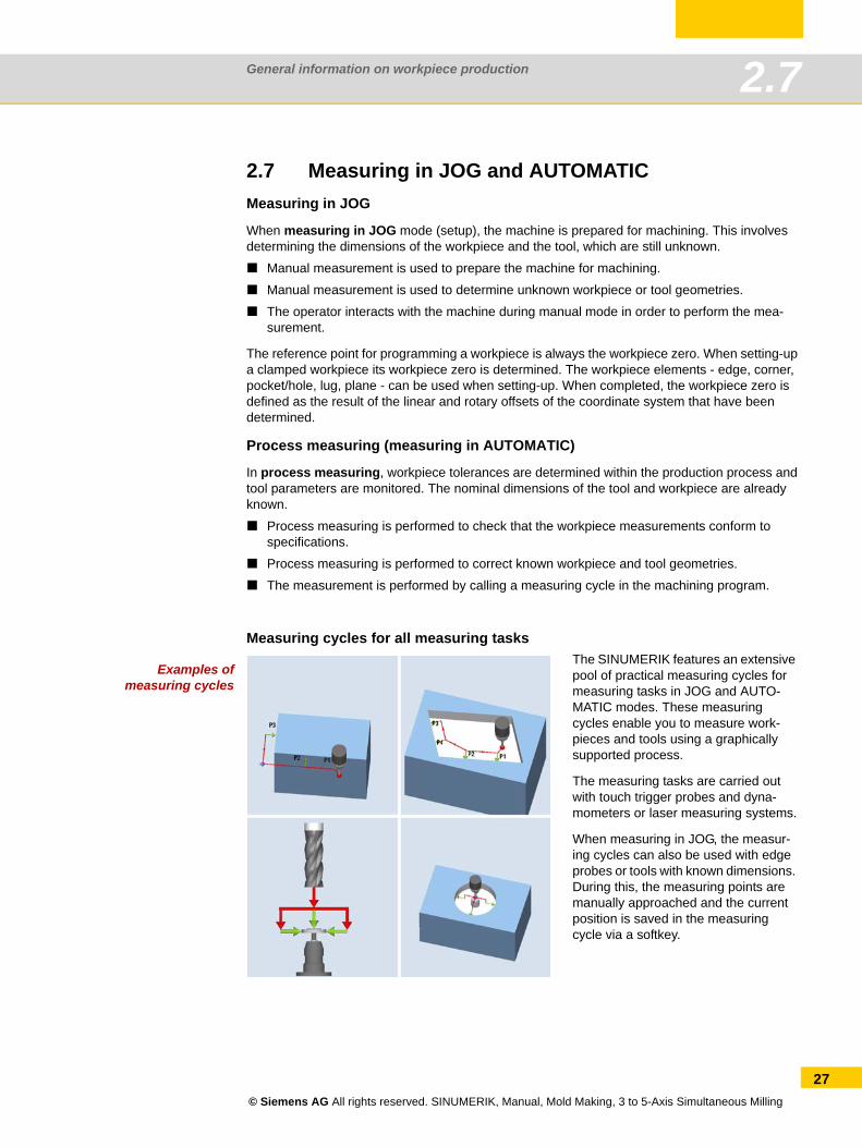
Examples ofmeasuring cycles
Measuring cycles for all measuring tasksThe SINUMERIK features an extensive pool of practical measuring cycles for measuring tasks in JOG and AUTO-MATIC modes. These measuring cycles enable you to measure work-pieces and tools using a graphically supported process.
The measuring tasks are carried out with touch trigger probes and dyna-mometers or laser measuring systems.
When measuring in JOG, the measur-ing cycles can also be used with edge probes or tools with known dimensions. During this, the measuring points are manually approached and the current position is saved in the measuring cycle via a softkey.
© Siemens AG All rights reserved. SINUMERIK, Manual, Mold Making, 3 to 5-Axis Simultaneous Milling
27
General information on workpiece production2.8
28
2.8 Workpiece measuring in JOGOnce the machine has been powered up and the reference point approached, the axis positions relate to the machine coordinate system. The work offset signals to the control the position of the workpiece in the machine coordinate system.
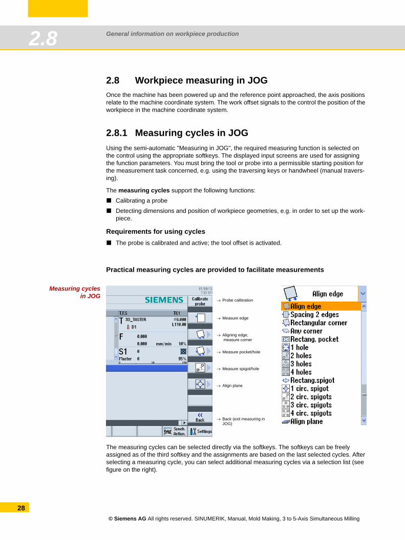
2.8.1 Measuring cycles in JOGUsing the semi-automatic "Measuring in JOG", the required measuring function is selected on the control using the appropriate softkeys. The displayed input screens are used for assigning the function parameters. You must bring the tool or probe into a permissible starting position for the measurement task concerned, e.g. using the traversing keys or handwheel (manual travers-ing).
The measuring cycles support the following functions:
Calibrating a probe
Detecting dimensions and position of workpiece geometries, e.g. in order to set up the work-piece.
Requirements for using cyclesThe probe is calibrated and active; the tool offset is activated.
Practical measuring cycles are provided to facilitate measurements
Measuring cyclesin JOG
The measuring cycles can be selected directly via the softkeys. The softkeys can be freely assigned as of the third softkey and the assignments are based on the last selected cycles. After selecting a measuring cycle, you can select additional measuring cycles via a selection list (see figure on the right).
→ Measure edge
→ Aligning edge; measure corner
→ Measure pocket/hole
→ Measure spigot/hole
→ Align plane
→ Probe calibration
→ Back (exit measuring in JOG)
© Siemens AG All rights reserved. SINUMERIK, Manual, Mold Making, 3 to 5-Axis Simultaneous Milling
General information on workpiece production 2.8
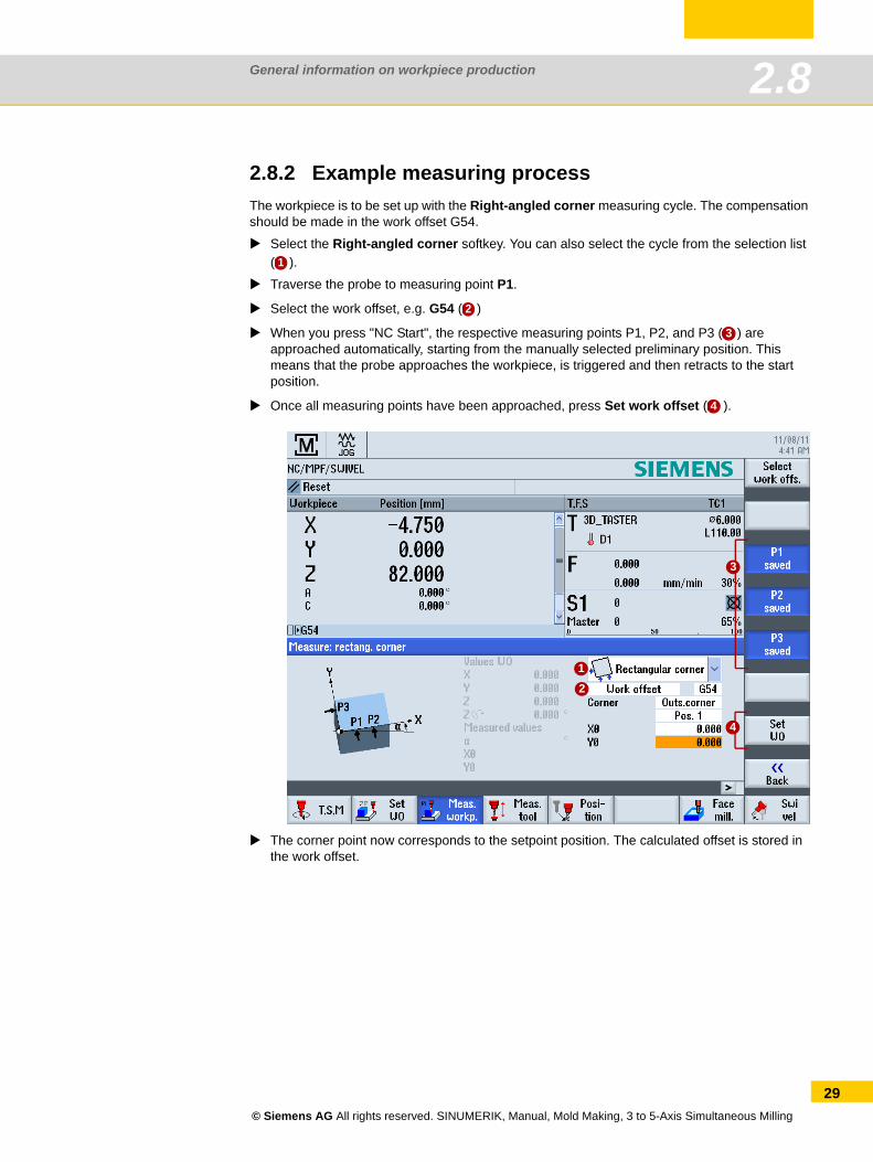
2.8.2 Example measuring processThe workpiece is to be set up with the Right-angled corner measuring cycle. The compensation should be made in the work offset G54.
Select the Right-angled corner softkey. You can also select the cycle from the selection list ( ).
Traverse the probe to measuring point P1.
Select the work offset, e.g. G54 ( )
When you press "NC Start", the respective measuring points P1, P2, and P3 ( ) are approached automatically, starting from the manually selected preliminary position. This means that the probe approaches the workpiece, is triggered and then retracts to the start position.
Once all measuring points have been approached, press Set work offset ( ).
The corner point now corresponds to the setpoint position. The calculated offset is stored in the work offset.
1
2
3
4
1
2
3
4
© Siemens AG All rights reserved. SINUMERIK, Manual, Mold Making, 3 to 5-Axis Simultaneous Milling
29
General information on workpiece production2.9
30
2.9 Measure tool in JOGWhen executing a program, the various tool geometries must be taken into account. These are stored as tool offset data in the tool list. When the tool is called, the control considers the tool off-set data.
You can determine the tool offset data (i.e. the length and radius or diameter) either via special tool pre-setting devices or with the aid of the measuring cycles on the machine.
2.9.1 Tool reference point
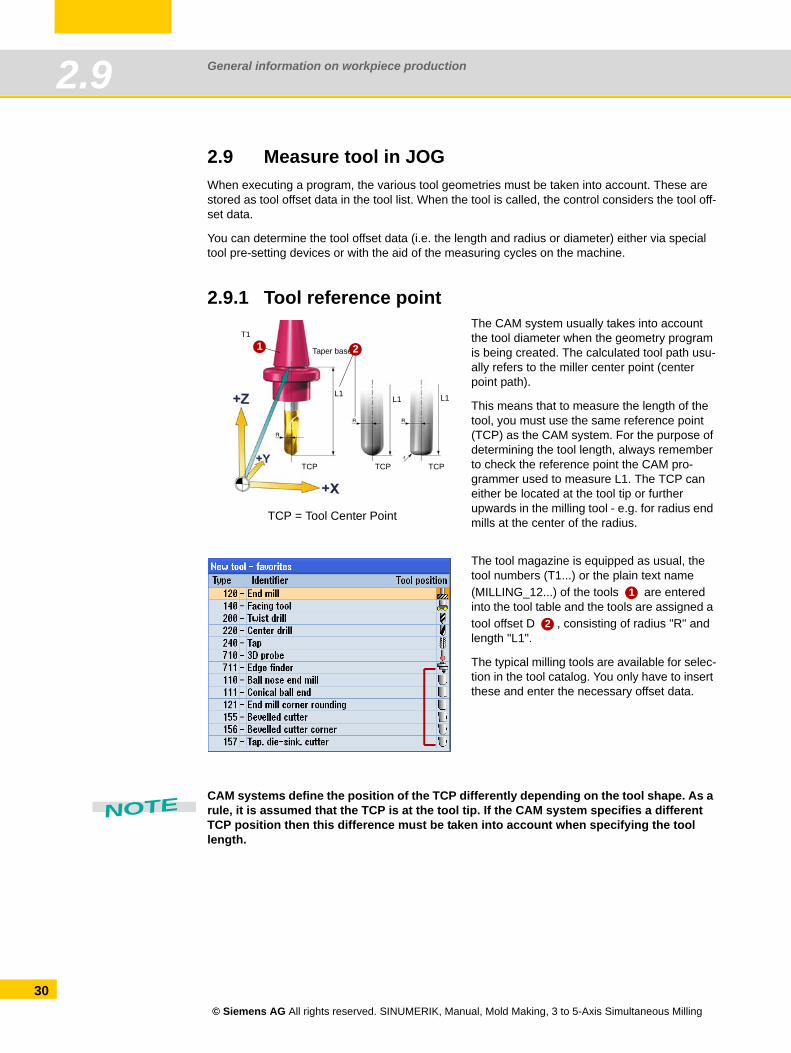
CAM systems define the position of the TCP differently depending on the tool shape. As a rule, it is assumed that the TCP is at the tool tip. If the CAM system specifies a different TCP position then this difference must be taken into account when specifying the tool length.
The CAM system usually takes into account the tool diameter when the geometry program is being created. The calculated tool path usu-ally refers to the miller center point (center point path).
This means that to measure the length of the tool, you must use the same reference point (TCP) as the CAM system. For the purpose of determining the tool length, always remember to check the reference point the CAM pro-grammer used to measure L1. The TCP can either be located at the tool tip or further upwards in the milling tool - e.g. for radius end mills at the center of the radius.
The tool magazine is equipped as usual, the tool numbers (T1...) or the plain text name (MILLING_12...) of the tools are entered into the tool table and the tools are assigned a tool offset D , consisting of radius "R" and length "L1".
The typical milling tools are available for selec-tion in the tool catalog. You only have to insert these and enter the necessary offset data.
1
TCP = Tool Center Point
TCP TCP TCP
T1
L1L1 L1
Taper base2
1
2
NOTE
© Siemens AG All rights reserved. SINUMERIK, Manual, Mold Making, 3 to 5-Axis Simultaneous Milling
General information on workpiece production 2.9
2.9.2 Example: Measure tool in JOG Function
The "Measure tool" function permits the following functions:
Calibrating a dynamometer
Determining the tool length or the radius of milling tools or the tool length of drills and entering this data into the tool offset memory.
Requirements for using cyclesThe tool must have been loaded.
The dynamometer is calibrated and active.
Procedure
In JOG mode, select the Measure tool softkey . In the horizontal softkey bar, select whether you want to measure automatically or manually.
Click on the corresponding softkey Radius Auto or Length Auto and enter the offset, especially for tools with rounded cuts, for example.
Click NC Start to initiate the measuring process; the tool offsets for radius and length 1 will be entered in the active tool offset data.
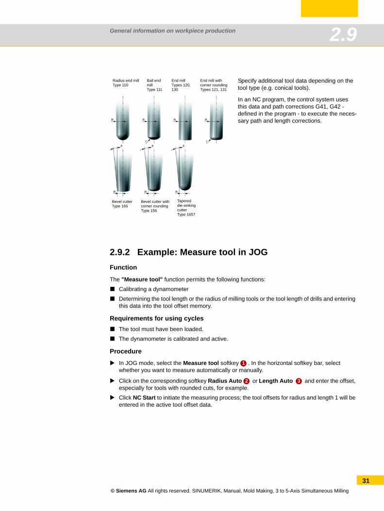
Specify additional tool data depending on the tool type (e.g. conical tools).
In an NC program, the control system uses this data and path corrections G41, G42 - defined in the program - to execute the neces-sary path and length corrections.
Radius end millType 110
Ball endmillType 111
End millTypes 120, 130
End mill with corner roundingTypes 121, 131
Bevel cutterType 165
Bevel cutter withcorner roundingType 156
Tapereddie-sinkingcutterType 1657
1
2 3
© Siemens AG All rights reserved. SINUMERIK, Manual, Mold Making, 3 to 5-Axis Simultaneous Milling
31
General information on workpiece production2.9
32
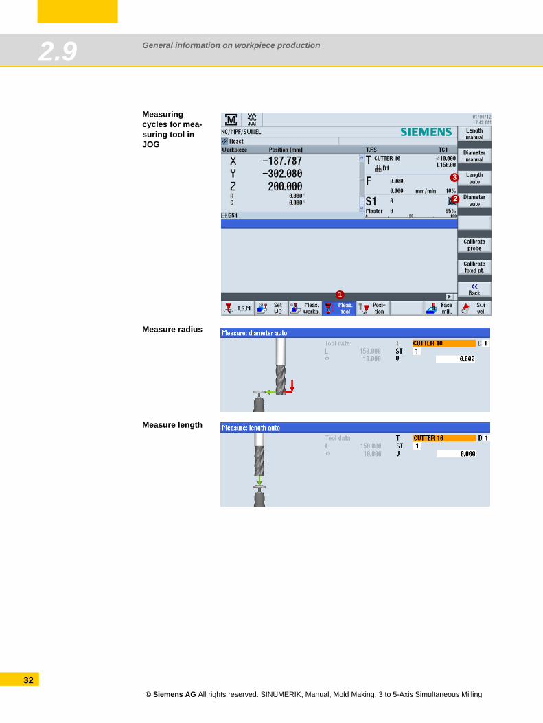
Measuring cycles for mea-suring tool in JOG
Measure radius
Measure length
1
2
3
© Siemens AG All rights reserved. SINUMERIK, Manual, Mold Making, 3 to 5-Axis Simultaneous Milling
General information on workpiece production 2.10
2.10 Workpiece measuring in AUTOMATIC - process measuring
For process measuring in Automatic mode, measuring cycle are specifically parameterized for the measuring task. The input screens of the program editor are used for parameter assignment. The measuring points to be approached and the measuring task are automatically implemented in accordance with the measuring program.
The workpiece is measured to determine workpiece tolerances in the production process. Depending on the measuring cycle used, you can select the following options as the result of workpiece measurement:
Measurement only without offsets (actual value is measured)
Work offset compensation (setpoint - actual value deviation)
Tool data offset (setpoint - actual value deviation)
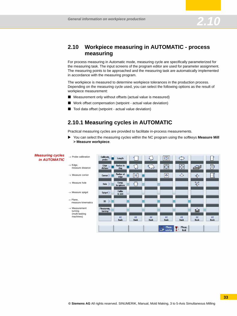
2.10.1 Measuring cycles in AUTOMATICPractical measuring cycles are provided to facilitate in-process measurements.
You can select the measuring cycles within the NC program using the softkeys Measure Mill > Measure workpiece.
Measuring cyclesin AUTOMATIC
→ Probe calibration
→ Edge,measure distance
→ Measure corner
→ Measure hole
→ Measure spigot
→ Plane,measure kinematics
→ Measurementturning(multi-tasking machines)
© Siemens AG All rights reserved. SINUMERIK, Manual, Mold Making, 3 to 5-Axis Simultaneous Milling
33
General information on workpiece production2.10
34
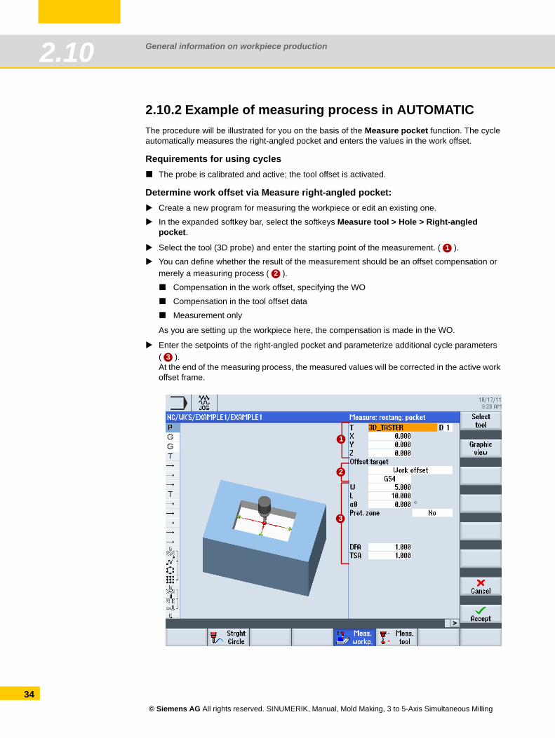
2.10.2 Example of measuring process in AUTOMATICThe procedure will be illustrated for you on the basis of the Measure pocket function. The cycle automatically measures the right-angled pocket and enters the values in the work offset.
Requirements for using cyclesThe probe is calibrated and active; the tool offset is activated.
Determine work offset via Measure right-angled pocket:Create a new program for measuring the workpiece or edit an existing one.
In the expanded softkey bar, select the softkeys Measure tool > Hole > Right-angled pocket.
Select the tool (3D probe) and enter the starting point of the measurement. ( ).
You can define whether the result of the measurement should be an offset compensation or merely a measuring process ( ).
Compensation in the work offset, specifying the WO
Compensation in the tool offset data
Measurement only
As you are setting up the workpiece here, the compensation is made in the WO.
Enter the setpoints of the right-angled pocket and parameterize additional cycle parameters ( ). At the end of the measuring process, the measured values will be corrected in the active work offset frame.
1
2
3
1
2
3
© Siemens AG All rights reserved. SINUMERIK, Manual, Mold Making, 3 to 5-Axis Simultaneous Milling
General information on workpiece production 2.11
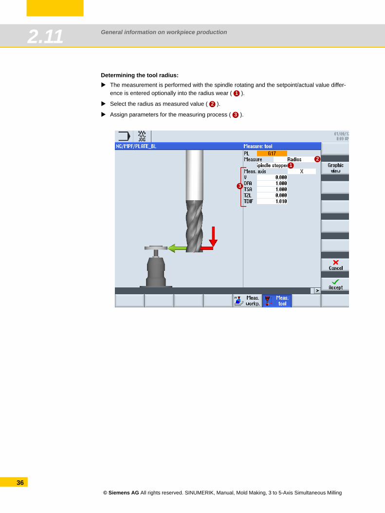
2.11 Tool measuring in AUTOMATIC - process measur-ing
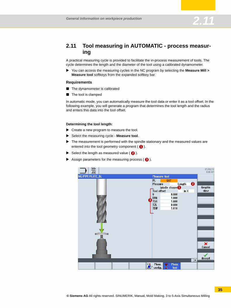
A practical measuring cycle is provided to facilitate the in-process measurement of tools. The cycle determines the length and the diameter of the tool using a calibrated dynamometer.
You can access the measuring cycles in the NC program by selecting the Measure Mill > Measure tool softkeys from the expanded softkey bar.
RequirementsThe dynamometer is calibrated
The tool is clamped
In automatic mode, you can automatically measure the tool data or enter it as a tool offset. In the following example, you will generate a program that determines the tool length and the radius and enters this data into the tool offset.
Determining the tool length:Create a new program to measure the tool.
Select the measuring cycle - Measure tool.The measurement is performed with the spindle stationary and the measured values are entered into the tool geometry component ( ).
Select the length as measured value ( ).
Assign parameters for the measuring process ( ).
1
2
3
12
3
© Siemens AG All rights reserved. SINUMERIK, Manual, Mold Making, 3 to 5-Axis Simultaneous Milling
35
General information on workpiece production2.11
36
Determining the tool radius:The measurement is performed with the spindle rotating and the setpoint/actual value differ-ence is entered optionally into the radius wear ( ).
Select the radius as measured value ( ).
Assign parameters for the measuring process ( ).
1
2
3
12
3
© Siemens AG All rights reserved. SINUMERIK, Manual, Mold Making, 3 to 5-Axis Simultaneous Milling
General information on workpiece production 2.12
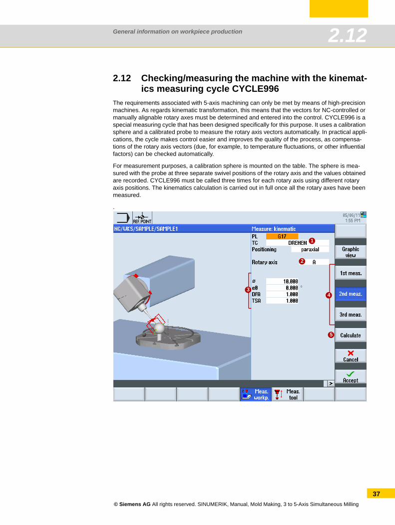
2.12 Checking/measuring the machine with the kinemat-ics measuring cycle CYCLE996
The requirements associated with 5-axis machining can only be met by means of high-precision machines. As regards kinematic transformation, this means that the vectors for NC-controlled or manually alignable rotary axes must be determined and entered into the control. CYCLE996 is a special measuring cycle that has been designed specifically for this purpose. It uses a calibration sphere and a calibrated probe to measure the rotary axis vectors automatically. In practical appli-cations, the cycle makes control easier and improves the quality of the process, as compensa-tions of the rotary axis vectors (due, for example, to temperature fluctuations, or other influential factors) can be checked automatically.
For measurement purposes, a calibration sphere is mounted on the table. The sphere is mea-sured with the probe at three separate swivel positions of the rotary axis and the values obtained are recorded. CYCLE996 must be called three times for each rotary axis using different rotary axis positions. The kinematics calculation is carried out in full once all the rotary axes have been measured.
.
1
2
5
43
© Siemens AG All rights reserved. SINUMERIK, Manual, Mold Making, 3 to 5-Axis Simultaneous Milling
37
General information on workpiece production2.12
38
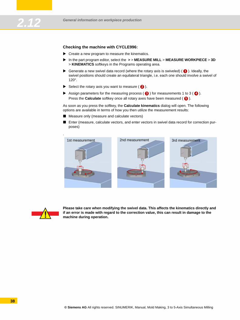
Checking the machine with CYCLE996:Create a new program to measure the kinematics.
In the part program editor, select the > > MEASURE MILL > MEASURE WORKPIECE > 3D > KINEMATICS softkeys in the Programs operating area.
Generate a new swivel data record (where the rotary axis is swiveled) ( ). Ideally, the swivel positions should create an equilateral triangle, i.e. each one should involve a swivel of 120°.
Select the rotary axis you want to measure ( ).
Assign parameters for the measuring process ( ) for measurements 1 to 3 ( ).Press the Calculate softkey once all rotary axes have been measured ( ).
As soon as you press the softkey, the Calculate kinematics dialog will open. The following options are available in terms of how you then utilize the measurement results:
Measure only (measure and calculate vectors)
Enter (measure, calculate vectors, and enter vectors in swivel data record for correction pur-poses)
.
Please take care when modifying the swivel data. This affects the kinematics directly and if an error is made with regard to the correction value, this can result in damage to the machine during operation.
1
2
3 45
1st measurement 2nd measurement 3rd measurement
!
© Siemens AG All rights reserved. SINUMERIK, Manual, Mold Making, 3 to 5-Axis Simultaneous Milling
General information on workpiece production 2.13
2.13 Workpiece visualization
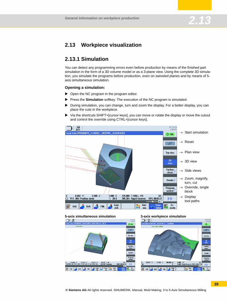
2.13.1 SimulationYou can detect any programming errors even before production by means of the finished part simulation in the form of a 3D volume model or as a 3-plane view. Using the complete 3D simula-tion, you simulate the programs before production, even on swiveled planes and by means of 5-axis simultaneous simulation.
Opening a simulation:Open the NC program in the program editor.
Press the Simulation softkey. The execution of the NC program is simulated.
During simulation, you can change, turn and zoom the display. For a better display, you can place the cuts in the workpiece.
Via the shortcuts SHIFT+[cursor keys], you can move or rotate the display or move the cutout and control the override using CTRL+[cursor keys].
5-axis simultaneous simulation 3-axis workpiece simulation
→ Start simulation
→ Reset
→ Override, single block
→ Zoom, magnify, turn, cut
→ Displaytool paths
→ Plan view
→ 3D view
→ Side views
© Siemens AG All rights reserved. SINUMERIK, Manual, Mold Making, 3 to 5-Axis Simultaneous Milling
39
General information on workpiece production2.13
40
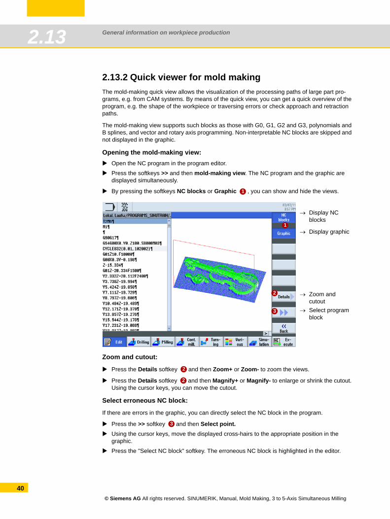
2.13.2 Quick viewer for mold makingThe mold-making quick view allows the visualization of the processing paths of large part pro-grams, e.g. from CAM systems. By means of the quick view, you can get a quick overview of the program, e.g. the shape of the workpiece or traversing errors or check approach and retraction paths.
The mold-making view supports such blocks as those with G0, G1, G2 and G3, polynomials and B splines, and vector and rotary axis programming. Non-interpretable NC blocks are skipped and not displayed in the graphic.
Opening the mold-making view:Open the NC program in the program editor.
Press the softkeys >> and then mold-making view. The NC program and the graphic are displayed simultaneously.
By pressing the softkeys NC blocks or Graphic , you can show and hide the views.
Zoom and cutout:
Press the Details softkey and then Zoom+ or Zoom- to zoom the views.
Press the Details softkey and then Magnify+ or Magnify- to enlarge or shrink the cutout. Using the cursor keys, you can move the cutout.
Select erroneous NC block:
If there are errors in the graphic, you can directly select the NC block in the program.
Press the >> softkey and then Select point.Using the cursor keys, move the displayed cross-hairs to the appropriate position in the graphic.
Press the "Select NC block" softkey. The erroneous NC block is highlighted in the editor.
1
→ Display NC blocks
→ Display graphic
→ Select program block
→ Zoom and cutout
3
1
2
2
2
3
© Siemens AG All rights reserved. SINUMERIK, Manual, Mold Making, 3 to 5-Axis Simultaneous Milling
Important functions 3 to 5-axis machining
Content Page3.1 Introduction 423.2 Explanation of the terms swivel, frames and TRAORI 433.3 Transforming coordinate systems - Frames 443.4 Swivel - CYCLE800 453.5 TRAORI 5-axis transformation 513.6 High Speed Settings - CYCLE832 Advanced Surface 663.7 Advanced Surface - NC commands 693.8 3D tool radius compensations 793.9 Volumetric compensation system (VCS) 823.10 VNCK - Virtual machine 83
Important functions 3 to 5-axis machining3.1
42
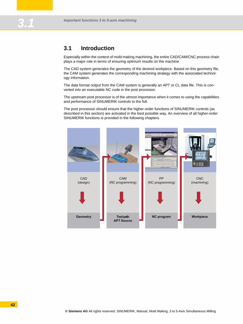
3.1 IntroductionEspecially within the context of mold making machining, the entire CAD/CAM/CNC process chain plays a major role in terms of ensuring optimum results on the machine.
The CAD system generates the geometry of the desired workpiece. Based on this geometry file, the CAM system generates the corresponding machining strategy with the associated technol-ogy information.
The data format output from the CAM system is generally an APT or CL data file. This is con-verted into an executable NC code in the post processor.
The upstream post processor is of the utmost importance when it comes to using the capabilities and performance of SINUMERIK controls to the full.
The post processor should ensure that the higher-order functions of SINUMERIK controls (as described in this section) are activated in the best possible way. An overview of all higher-order SINUMERIK functions is provided in the following chapters.
CAD(design)
CAM(NC programming)
PP(NC programming)
CNC(machining)
Geometry Tool pathAPT Source
NC program Workpiece
© Siemens AG All rights reserved. SINUMERIK, Manual, Mold Making, 3 to 5-Axis Simultaneous Milling
Important functions 3 to 5-axis machining 3.2
3.2 Explanation of the terms swivel, frames and TRAORI
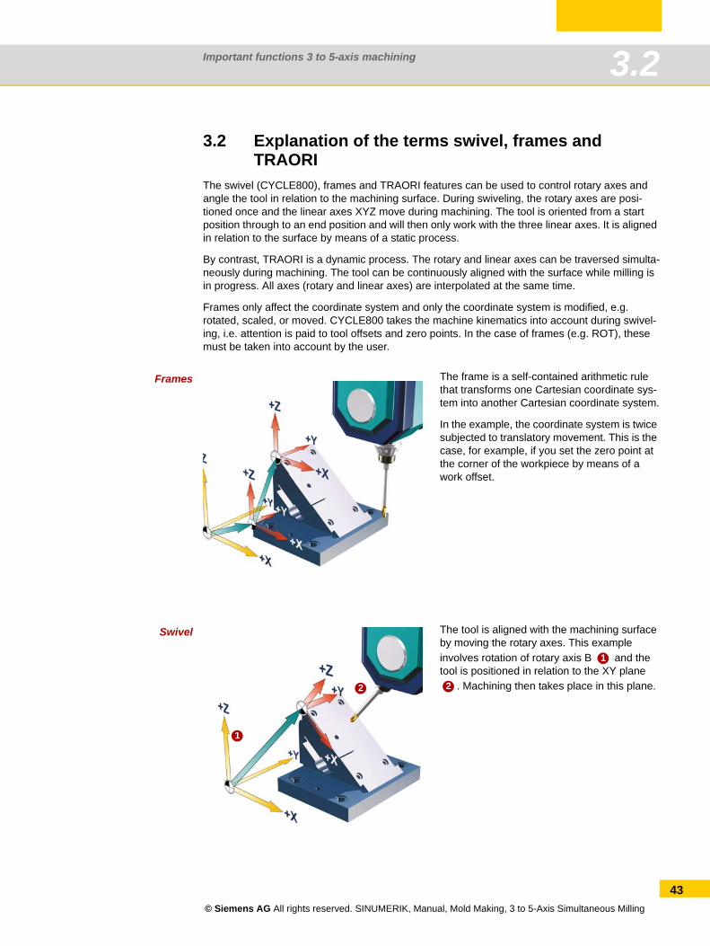
The swivel (CYCLE800), frames and TRAORI features can be used to control rotary axes and angle the tool in relation to the machining surface. During swiveling, the rotary axes are posi-tioned once and the linear axes XYZ move during machining. The tool is oriented from a start position through to an end position and will then only work with the three linear axes. It is aligned in relation to the surface by means of a static process.
By contrast, TRAORI is a dynamic process. The rotary and linear axes can be traversed simulta-neously during machining. The tool can be continuously aligned with the surface while milling is in progress. All axes (rotary and linear axes) are interpolated at the same time.
Frames only affect the coordinate system and only the coordinate system is modified, e.g. rotated, scaled, or moved. CYCLE800 takes the machine kinematics into account during swivel-ing, i.e. attention is paid to tool offsets and zero points. In the case of frames (e.g. ROT), these must be taken into account by the user.
Frames
Swivel
The frame is a self-contained arithmetic rule that transforms one Cartesian coordinate sys-tem into another Cartesian coordinate system.
In the example, the coordinate system is twice subjected to translatory movement. This is the case, for example, if you set the zero point at the corner of the workpiece by means of a work offset.
The tool is aligned with the machining surface by moving the rotary axes. This example involves rotation of rotary axis B and the tool is positioned in relation to the XY plane
. Machining then takes place in this plane.
1
2
1
2
© Siemens AG All rights reserved. SINUMERIK, Manual, Mold Making, 3 to 5-Axis Simultaneous Milling
43
Important functions 3 to 5-axis machining3.3
44
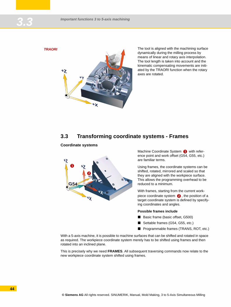
TRAORI
3.3 Transforming coordinate systems - FramesCoordinate systems
With a 5-axis machine, it is possible to machine surfaces that can be shifted and rotated in space as required. The workpiece coordinate system merely has to be shifted using frames and then rotated into an inclined plane.
This is precisely why we need FRAMES. All subsequent traversing commands now relate to the new workpiece coordinate system shifted using frames.
The tool is aligned with the machining surface dynamically during the milling process by means of linear and rotary axis interpolation. The tool length is taken into account and the kinematic compensating movements are initi-ated by the TRAORI function when the rotary axes are rotated.
Machine Coordinate System with refer-ence point and work offset (G54, G55, etc.) are familiar terms.
Using frames, the coordinate systems can be shifted, rotated, mirrored and scaled so that they are aligned with the workpiece surface. This allows the programming overhead to be reduced to a minimum.
With frames, starting from the current work-piece coordinate system , the position of a target coordinate system is defined by specify-ing coordinates and angles.
Possible frames includeBasic frame (basic offset, G500)
Settable frames (G54, G55, etc.)
Programmable frames (TRANS, ROT, etc.)
1
2
1
2
© Siemens AG All rights reserved. SINUMERIK, Manual, Mold Making, 3 to 5-Axis Simultaneous Milling
Important functions 3 to 5-axis machining 3.4
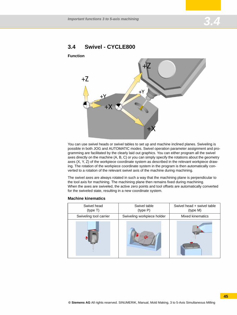
3.4 Swivel - CYCLE800Function
You can use swivel heads or swivel tables to set up and machine inclined planes. Swiveling is possible in both JOG and AUTOMATIC modes. Swivel operation parameter assignment and pro-gramming are facilitated by the clearly laid out graphics. You can either program all the swivel axes directly on the machine (A, B, C) or you can simply specify the rotations about the geometry axes (X, Y, Z) of the workpiece coordinate system as described in the relevant workpiece draw-ing. The rotation of the workpiece coordinate system in the program is then automatically con-verted to a rotation of the relevant swivel axis of the machine during machining.
The swivel axes are always rotated in such a way that the machining plane is perpendicular to the tool axis for machining. The machining plane then remains fixed during machining.When the axes are swiveled, the active zero points and tool offsets are automatically converted for the swiveled state, resulting in a new coordinate system.
Machine kinematics
Swivel head (type T)
Swivel table(type P)
Swivel head + swivel table(type M)
Swiveling tool carrier Swiveling workpiece holder Mixed kinematics
© Siemens AG All rights reserved. SINUMERIK, Manual, Mold Making, 3 to 5-Axis Simultaneous Milling
45
Important functions 3 to 5-axis machining3.4
46
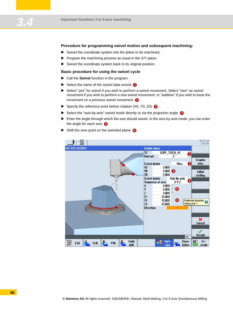
Procedure for programming swivel motion and subsequent machining:Swivel the coordinate system into the plane to be machined.
Program the machining process as usual in the X/Y plane.
Swivel the coordinate system back to its original position.
Basic procedure for using the swivel cycleCall the Swivel function in the program.
Select the name of the swivel data record .
Select "yes" for swivel if you wish to perform a swivel movement. Select "new" as swivel movement if you wish to perform a new swivel movement, or "additive" if you wish to base the movement on a previous swivel movement .
Specify the reference point before rotation (X0, Y0, Z0) .
Select the "axis-by-axis" swivel mode directly or via the projection angle .
Enter the angle through which the axis should swivel. In the axis-by-axis mode, you can enter the angle for each axis .
Shift the zero point on the swiveled plane .
1
2
3
4
5
6
1
2
3
4
5
6
© Siemens AG All rights reserved. SINUMERIK, Manual, Mold Making, 3 to 5-Axis Simultaneous Milling
Important functions 3 to 5-axis machining 3.4
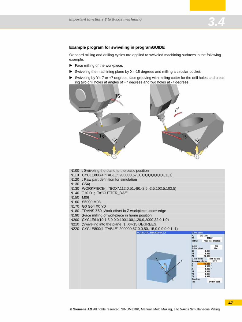
Example program for swiveling in programGUIDE
Standard milling and drilling cycles are applied to swiveled machining surfaces in the following example.
Face milling of the workpiece.
Swiveling the machining plane by X=-15 degrees and milling a circular pocket.
Swiveling by Y=-7 or +7 degrees, face grooving with milling cutter for the drill holes and creat-ing two drill holes at angles of +7 degrees and two holes at -7 degrees.
N100 ; Swiveling the plane to the basic positionN110 CYCLE800(4,"TABLE",200000,57,0,0,0,0,0,0,0,0,0,1,,1)N120 ; Raw part definition for simulationN130 G54)N130 WORKPIECE(,,,"BOX",112,0,51,-80,-2.5,-2.5,102.5,102.5)N140 T10 D1; T="CUTTER_D32"N150 M06N160 S5000 M03N170 G0 G54 X0 Y0N180 TRANS Z50 ;Work offset in Z workpiece upper edgeN190 ;Face milling of workpiece in home positionN200 CYCLE61(10,1,5,0,0,0,100,100,1,20,0,2000,32,0,1,0)N210 ;Swiveling into the plane_1 X=-15 DEGREES N220 CYCLE800(4,"TABLE",200000,57,0,0,50,-15,0,0,0,0,0,1,,1)
© Siemens AG All rights reserved. SINUMERIK, Manual, Mold Making, 3 to 5-Axis Simultaneous Milling
47
Important functions 3 to 5-axis machining3.4
48
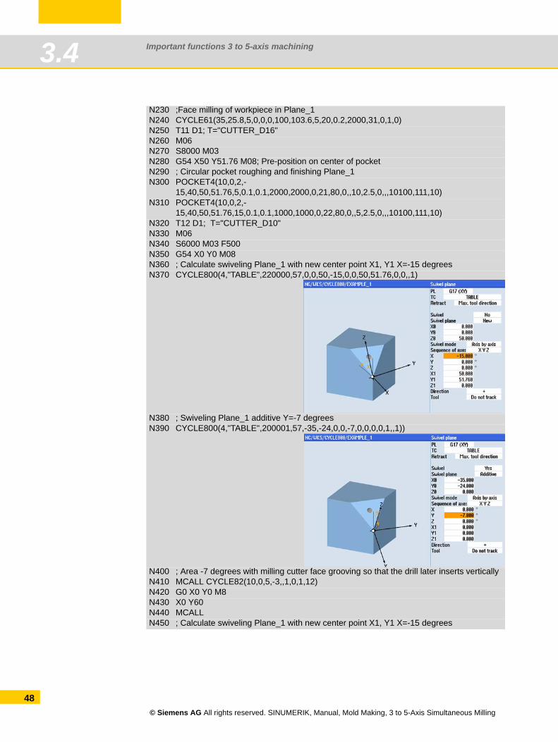
N230 ;Face milling of workpiece in Plane_1N240 CYCLE61(35,25.8,5,0,0,0,100,103.6,5,20,0.2,2000,31,0,1,0)N250 T11 D1; T="CUTTER_D16" N260 M06N270 S8000 M03N280 G54 X50 Y51.76 M08; Pre-position on center of pocketN290 ; Circular pocket roughing and finishing Plane_1N300 POCKET4(10,0,2,-
15,40,50,51.76,5,0.1,0.1,2000,2000,0,21,80,0,,10,2.5,0,,,10100,111,10)N310 POCKET4(10,0,2,-
15,40,50,51.76,15,0.1,0.1,1000,1000,0,22,80,0,,5,2.5,0,,,10100,111,10)N320 T12 D1; T="CUTTER_D10" N330 M06N340 S6000 M03 F500N350 G54 X0 Y0 M08N360 ; Calculate swiveling Plane_1 with new center point X1, Y1 X=-15 degreesN370 CYCLE800(4,"TABLE",220000,57,0,0,50,-15,0,0,50,51.76,0,0,,1)
N380 ; Swiveling Plane_1 additive Y=-7 degreesN390 CYCLE800(4,"TABLE",200001,57,-35,-24,0,0,-7,0,0,0,0,1,,1))
N400 ; Area -7 degrees with milling cutter face grooving so that the drill later inserts verticallyN410 MCALL CYCLE82(10,0,5,-3,,1,0,1,12)N420 G0 X0 Y0 M8N430 X0 Y60N440 MCALLN450 ; Calculate swiveling Plane_1 with new center point X1, Y1 X=-15 degrees
© Siemens AG All rights reserved. SINUMERIK, Manual, Mold Making, 3 to 5-Axis Simultaneous Milling
Important functions 3 to 5-axis machining 3.4
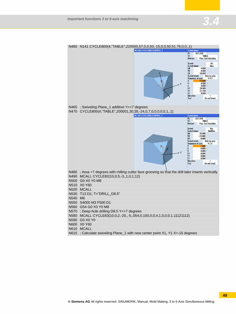
N460 N141 CYCLE800(4,"TABLE",220000,57,0,0,50,-15,0,0,50,51.76,0,0,,1)
N465 ; Swiveling Plane_1 additive Y=+7 degreesN470 CYCLE800(4,"TABLE",200001,30,35,-24,0,7,0,0,0,0,0,1,,1)
N480 ; Area +7 degrees with milling cutter face grooving so that the drill later inserts verticallyN490 MCALL CYCLE82(10,0,5,-3,,1,0,1,12)N500 G0 X0 Y0 M8N510 X0 Y60N520 MCALLN530 T13 D1; T="DRILL_D8.5"N540 M6N550 S4000 M3 F500 D1N560 G54 G0 X0 Y0 M8N570 ; Deep-hole drilling D8.5 Y=+7 degreesN580 MCALL CYCLE83(10,0,2,-20,,-5,,054,0,100,0,0,4,1,0,0,0,1,11121112)N590 G0 X0 Y0N600 X0 Y60N610 MCALLN615 ; Calculate swiveling Plane_1 with new center point X1, Y1 X=-15 degrees
© Siemens AG All rights reserved. SINUMERIK, Manual, Mold Making, 3 to 5-Axis Simultaneous Milling
49
Important functions 3 to 5-axis machining3.4
50
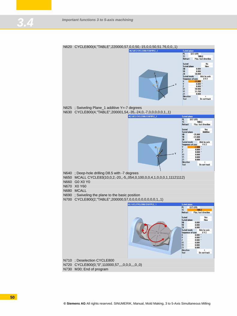
N620 CYCLE800(4,"TABLE",220000,57,0,0,50,-15,0,0,50,51.76,0,0,,1)
N625 ; Swiveling Plane_1 additive Y=-7 degreesN630 CYCLE800(4,"TABLE",200001,54,-35,-24,0,-7,0,0,0,0,0,1,,1)
N640 ; Deep-hole drilling D8.5 with -7 degreesN650 MCALL CYCLE83(10,0,2,-20,,-5,,054,0,100,0,0,4,1,0,0,0,1,11121112)N660 G0 X0 Y0N670 X0 Y60N680 MCALLN690 ; Swiveling the plane to the basic positionN700 CYCLE800(2,"TABLE",200000,57,0,0,0,0,0,0,0,0,0,1,,1)
N710 ; Deselection CYCLE800N720 CYCLE800(0,"0",110000,57,,,,0,0,0,,,,0,,0)N730 M30; End of program
© Siemens AG All rights reserved. SINUMERIK, Manual, Mold Making, 3 to 5-Axis Simultaneous Milling
Important functions 3 to 5-axis machining 3.5
3.5 TRAORI 5-axis transformation
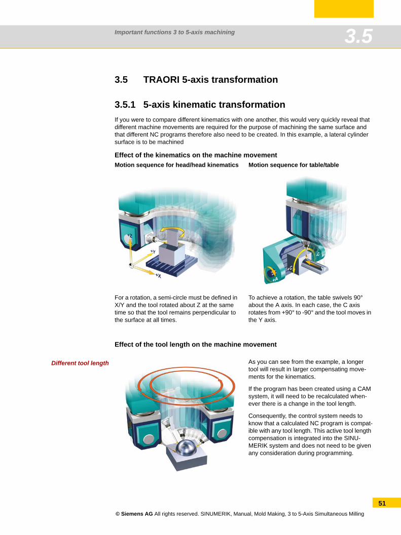
3.5.1 5-axis kinematic transformationIf you were to compare different kinematics with one another, this would very quickly reveal that different machine movements are required for the purpose of machining the same surface and that different NC programs therefore also need to be created. In this example, a lateral cylinder surface is to be machined
Effect of the kinematics on the machine movement
Effect of the tool length on the machine movement
Different tool length
Motion sequence for head/head kinematics Motion sequence for table/table
For a rotation, a semi-circle must be defined in X/Y and the tool rotated about Z at the same time so that the tool remains perpendicular to the surface at all times.
To achieve a rotation, the table swivels 90° about the A axis. In each case, the C axis rotates from +90° to -90° and the tool moves in the Y axis.
As you can see from the example, a longer tool will result in larger compensating move-ments for the kinematics.
If the program has been created using a CAM system, it will need to be recalculated when-ever there is a change in the tool length.
Consequently, the control system needs to know that a calculated NC program is compat-ible with any tool length. This active tool length compensation is integrated into the SINU-MERIK system and does not need to be given any consideration during programming.
© Siemens AG All rights reserved. SINUMERIK, Manual, Mold Making, 3 to 5-Axis Simultaneous Milling
51
Important functions 3 to 5-axis machining3.5
52
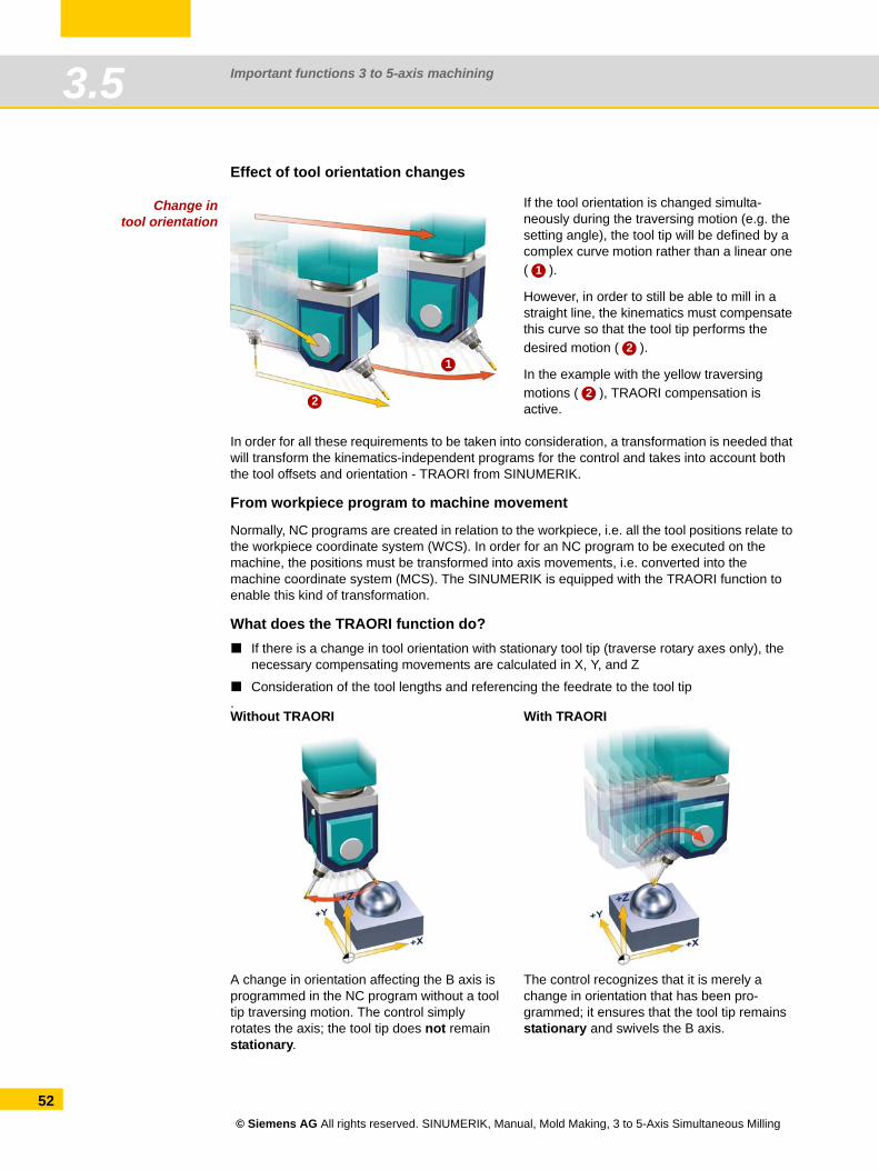
Effect of tool orientation changes
Change intool orientation
In order for all these requirements to be taken into consideration, a transformation is needed that will transform the kinematics-independent programs for the control and takes into account both the tool offsets and orientation - TRAORI from SINUMERIK.
From workpiece program to machine movement
Normally, NC programs are created in relation to the workpiece, i.e. all the tool positions relate to the workpiece coordinate system (WCS). In order for an NC program to be executed on the machine, the positions must be transformed into axis movements, i.e. converted into the machine coordinate system (MCS). The SINUMERIK is equipped with the TRAORI function to enable this kind of transformation.
What does the TRAORI function do?If there is a change in tool orientation with stationary tool tip (traverse rotary axes only), the necessary compensating movements are calculated in X, Y, and Z
Consideration of the tool lengths and referencing the feedrate to the tool tip.
If the tool orientation is changed simulta-neously during the traversing motion (e.g. the setting angle), the tool tip will be defined by a complex curve motion rather than a linear one ( ).
However, in order to still be able to mill in a straight line, the kinematics must compensate this curve so that the tool tip performs the desired motion ( ).
In the example with the yellow traversing motions ( ), TRAORI compensation is active.
Without TRAORI With TRAORI
A change in orientation affecting the B axis is programmed in the NC program without a tool tip traversing motion. The control simply rotates the axis; the tool tip does not remain stationary.
The control recognizes that it is merely a change in orientation that has been pro-grammed; it ensures that the tool tip remains stationary and swivels the B axis.
1
2
1
2
2
© Siemens AG All rights reserved. SINUMERIK, Manual, Mold Making, 3 to 5-Axis Simultaneous Milling
Important functions 3 to 5-axis machining 3.5
3.5.2 TRAORI programmingThere a numerous advantages to TRAORI programming. The program is independent of the tool length and machine kinematics, the feedrate relates to the tool tip and movements for compen-sating the movements of the rotary axes are performed automatically.
To obtain optimum cutting conditions when machining surfaces with a three-dimensional curve, it must be possible to vary the setting angle of the tool. This calls for at least one or two rotary axes in addition to the three linear axes X, Y, and Z. The NC blocks are expanded by means of the ori-entation information, e.g. A3, B3, C3 or A, B, and C.
When the transformation is enabled, the positional data (X, Y, Z) always relates to the tip of the tool, TCP. Changing the position of the rotary axes involved in the transformation causes such compensating movements of the remaining machine axes so that the position of the tool tip remains unchanged.
Programming
TRAORI(n) ; Transformation activatedTRAFOOF ; Transformation deactivated
Explanation of the commands
Depending on the configuration (depending on the machine manufacturer), TRAORI can reset the active work offset (e.g. G54) and the tool edge compensation (D1). Therefore it is recommended that the work offset and the tool edge compensation be activated again after TRAORI is called up.
TRAORI Activates the first configured orientation transformation.
TRAORI(n) Activates the orientation transformation configured with n.
n The number of the transformation (n = 1 or 2), TRAORI(1) corre-sponds to TRAORI.
TRAFOOF Deactivate transformation
NOTE
© Siemens AG All rights reserved. SINUMERIK, Manual, Mold Making, 3 to 5-Axis Simultaneous Milling
53
Important functions 3 to 5-axis machining3.5
54
3.5.3 Tool orientationFor the purpose of 5-axis simultaneous machining, the orientation of the tool needs to be defined in addition to the position setpoint of the machining point. There are a variety of methods that are commonly used to define the tool orientation. Generally speaking, 5-axis programs are created with the CAM system and the post processor is responsible for defining the type of orientation process used. The most commonly used interpolations are briefly described here.
Direction vector (A3= B3= C3=)
Explanation of the commands
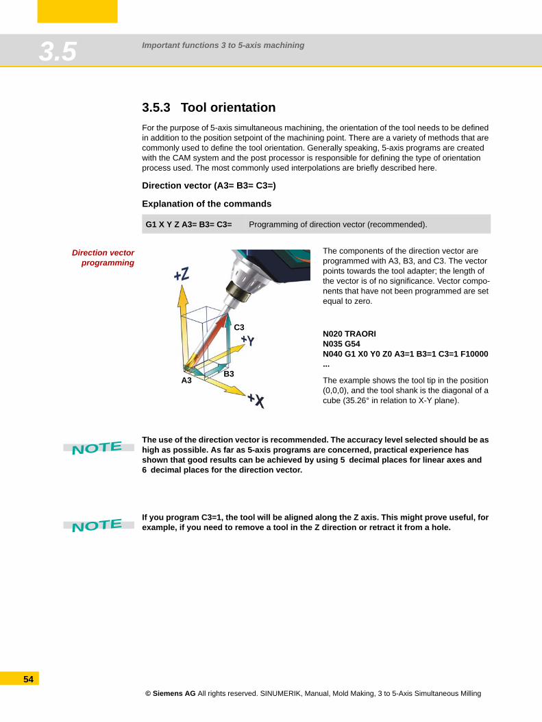
Direction vectorprogramming
The use of the direction vector is recommended. The accuracy level selected should be as high as possible. As far as 5-axis programs are concerned, practical experience has shown that good results can be achieved by using 5 decimal places for linear axes and 6 decimal places for the direction vector.
If you program C3=1, the tool will be aligned along the Z axis. This might prove useful, for example, if you need to remove a tool in the Z direction or retract it from a hole.
G1 X Y Z A3= B3= C3= Programming of direction vector (recommended).
The components of the direction vector are programmed with A3, B3, and C3. The vector points towards the tool adapter; the length of the vector is of no significance. Vector compo-nents that have not been programmed are set equal to zero.
N020 TRAORIN035 G54N040 G1 X0 Y0 Z0 A3=1 B3=1 C3=1 F10000...
The example shows the tool tip in the position (0,0,0), and the tool shank is the diagonal of a cube (35.26° in relation to X-Y plane).
C3
B3A3
NOTE
NOTE
© Siemens AG All rights reserved. SINUMERIK, Manual, Mold Making, 3 to 5-Axis Simultaneous Milling
Important functions 3 to 5-axis machining 3.5
Rotary axis positions (A= B= C=)
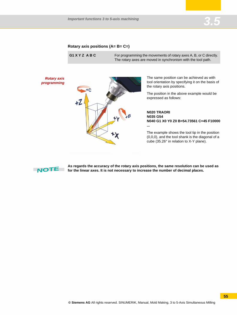
Rotary axisprogramming
As regards the accuracy of the rotary axis positions, the same resolution can be used as for the linear axes. It is not necessary to increase the number of decimal places.
G1 X Y Z A B C For programming the movements of rotary axes A, B, or C directly. The rotary axes are moved in synchronism with the tool path.
The same position can be achieved as with tool orientation by specifying it on the basis of the rotary axis positions.
The position in the above example would be expressed as follows:
N020 TRAORIN035 G54N040 G1 X0 Y0 Z0 B=54.73561 C=45 F10000...
The example shows the tool tip in the position (0,0,0), and the tool shank is the diagonal of a cube (35.26° in relation to X-Y plane).
NOTE
© Siemens AG All rights reserved. SINUMERIK, Manual, Mold Making, 3 to 5-Axis Simultaneous Milling
55
Important functions 3 to 5-axis machining3.5
56
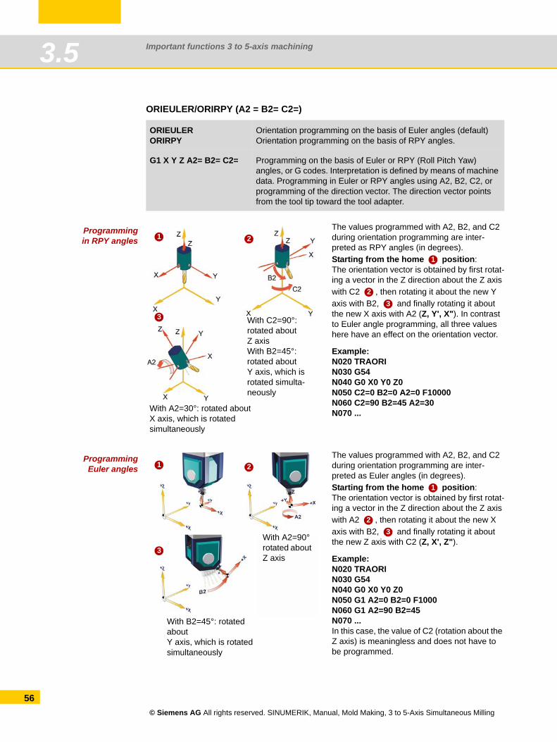
ORIEULER/ORIRPY (A2 = B2= C2=)
Programmingin RPY angles
ProgrammingEuler angles
ORIEULER ORIRPY
Orientation programming on the basis of Euler angles (default) Orientation programming on the basis of RPY angles.
G1 X Y Z A2= B2= C2= Programming on the basis of Euler or RPY (Roll Pitch Yaw) angles, or G codes. Interpretation is defined by means of machine data. Programming in Euler or RPY angles using A2, B2, C2, or programming of the direction vector. The direction vector points from the tool tip toward the tool adapter.
The values programmed with A2, B2, and C2 during orientation programming are inter-preted as RPY angles (in degrees).Starting from the home position:The orientation vector is obtained by first rotat-ing a vector in the Z direction about the Z axis with C2 , then rotating it about the new Y axis with B2, and finally rotating it about the new X axis with A2 (Z, Y', X"). In contrast to Euler angle programming, all three values here have an effect on the orientation vector.
Example:N020 TRAORIN030 G54N040 G0 X0 Y0 Z0N050 C2=0 B2=0 A2=0 F10000N060 C2=90 B2=45 A2=30N070 ...
1
3
2
With C2=90°: rotated aboutZ axisWith B2=45°: rotated aboutY axis, which is rotated simulta-neously
With A2=30°: rotated aboutX axis, which is rotated simultaneously
1
23
The values programmed with A2, B2, and C2 during orientation programming are inter-preted as Euler angles (in degrees).Starting from the home position:The orientation vector is obtained by first rotat-ing a vector in the Z direction about the Z axis with A2 , then rotating it about the new X axis with B2, and finally rotating it about the new Z axis with C2 (Z, X', Z").
Example:N020 TRAORIN030 G54N040 G0 X0 Y0 Z0N050 G1 A2=0 B2=0 F1000N060 G1 A2=90 B2=45N070 ...In this case, the value of C2 (rotation about the Z axis) is meaningless and does not have to be programmed.
1
3
2
With A2=90° rotated about Z axis
With B2=45°: rotated aboutY axis, which is rotated simultaneously
1
23
© Siemens AG All rights reserved. SINUMERIK, Manual, Mold Making, 3 to 5-Axis Simultaneous Milling
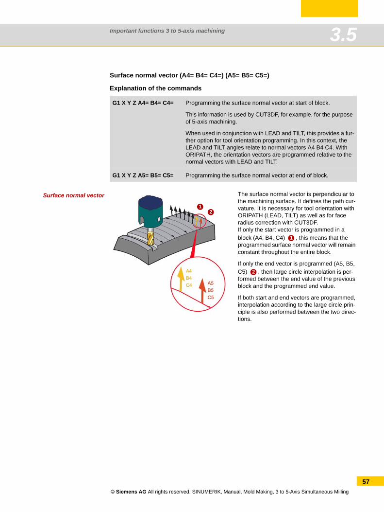
Important functions 3 to 5-axis machining 3.5
Surface normal vector (A4= B4= C4=) (A5= B5= C5=)
Explanation of the commands
Surface normal vector
G1 X Y Z A4= B4= C4= Programming the surface normal vector at start of block.
This information is used by CUT3DF, for example, for the purpose of 5-axis machining.
When used in conjunction with LEAD and TILT, this provides a fur-ther option for tool orientation programming. In this context, the LEAD and TILT angles relate to normal vectors A4 B4 C4. With ORIPATH, the orientation vectors are programmed relative to the normal vectors with LEAD and TILT.
G1 X Y Z A5= B5= C5= Programming the surface normal vector at end of block.
The surface normal vector is perpendicular to the machining surface. It defines the path cur-vature. It is necessary for tool orientation with ORIPATH (LEAD, TILT) as well as for face radius correction with CUT3DF.If only the start vector is programmed in a block (A4, B4, C4) , this means that the programmed surface normal vector will remain constant throughout the entire block.
If only the end vector is programmed (A5, B5, C5) , then large circle interpolation is per-formed between the end value of the previous block and the programmed end value.
If both start and end vectors are programmed, interpolation according to the large circle prin-ciple is also performed between the two direc-tions.
12
1
2
© Siemens AG All rights reserved. SINUMERIK, Manual, Mold Making, 3 to 5-Axis Simultaneous Milling
57
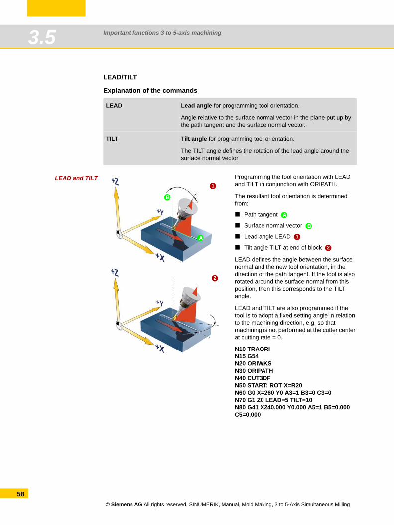
Important functions 3 to 5-axis machining3.5
58
LEAD/TILT
Explanation of the commands
LEAD and TILT
LEAD Lead angle for programming tool orientation.
Angle relative to the surface normal vector in the plane put up by the path tangent and the surface normal vector.
TILT Tilt angle for programming tool orientation.
The TILT angle defines the rotation of the lead angle around the surface normal vector
Programming the tool orientation with LEAD and TILT in conjunction with ORIPATH.
The resultant tool orientation is determined from:
Path tangent
Surface normal vector
Lead angle LEAD
Tilt angle TILT at end of block
LEAD defines the angle between the surface normal and the new tool orientation, in the direction of the path tangent. If the tool is also rotated around the surface normal from this position, then this corresponds to the TILT angle.
LEAD and TILT are also programmed if the tool is to adopt a fixed setting angle in relation to the machining direction, e.g. so that machining is not performed at the cutter center at cutting rate = 0.
N10 TRAORIN15 G54N20 ORIWKSN30 ORIPATHN40 CUT3DFN50 START: ROT X=R20N60 G0 X=260 Y0 A3=1 B3=0 C3=0N70 G1 Z0 LEAD=5 TILT=10N80 G41 X240.000 Y0.000 A5=1 B5=0.000 C5=0.000
1
2
A
B
A
B
1
2
© Siemens AG All rights reserved. SINUMERIK, Manual, Mold Making, 3 to 5-Axis Simultaneous Milling
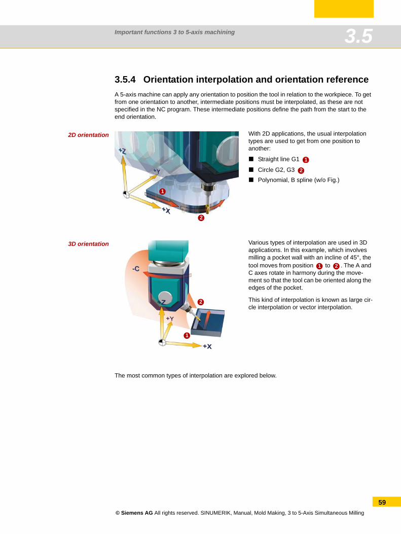
Important functions 3 to 5-axis machining 3.5
3.5.4 Orientation interpolation and orientation referenceA 5-axis machine can apply any orientation to position the tool in relation to the workpiece. To get from one orientation to another, intermediate positions must be interpolated, as these are not specified in the NC program. These intermediate positions define the path from the start to the end orientation.
2D orientation
3D orientation
The most common types of interpolation are explored below.
With 2D applications, the usual interpolation types are used to get from one position to another:
Straight line G1
Circle G2, G3
Polynomial, B spline (w/o Fig.)
1
2
1
2
Various types of interpolation are used in 3D applications. In this example, which involves milling a pocket wall with an incline of 45°, the tool moves from position to . The A and C axes rotate in harmony during the move-ment so that the tool can be oriented along the edges of the pocket.
This kind of interpolation is known as large cir-cle interpolation or vector interpolation.
1
2
1 2
© Siemens AG All rights reserved. SINUMERIK, Manual, Mold Making, 3 to 5-Axis Simultaneous Milling
59
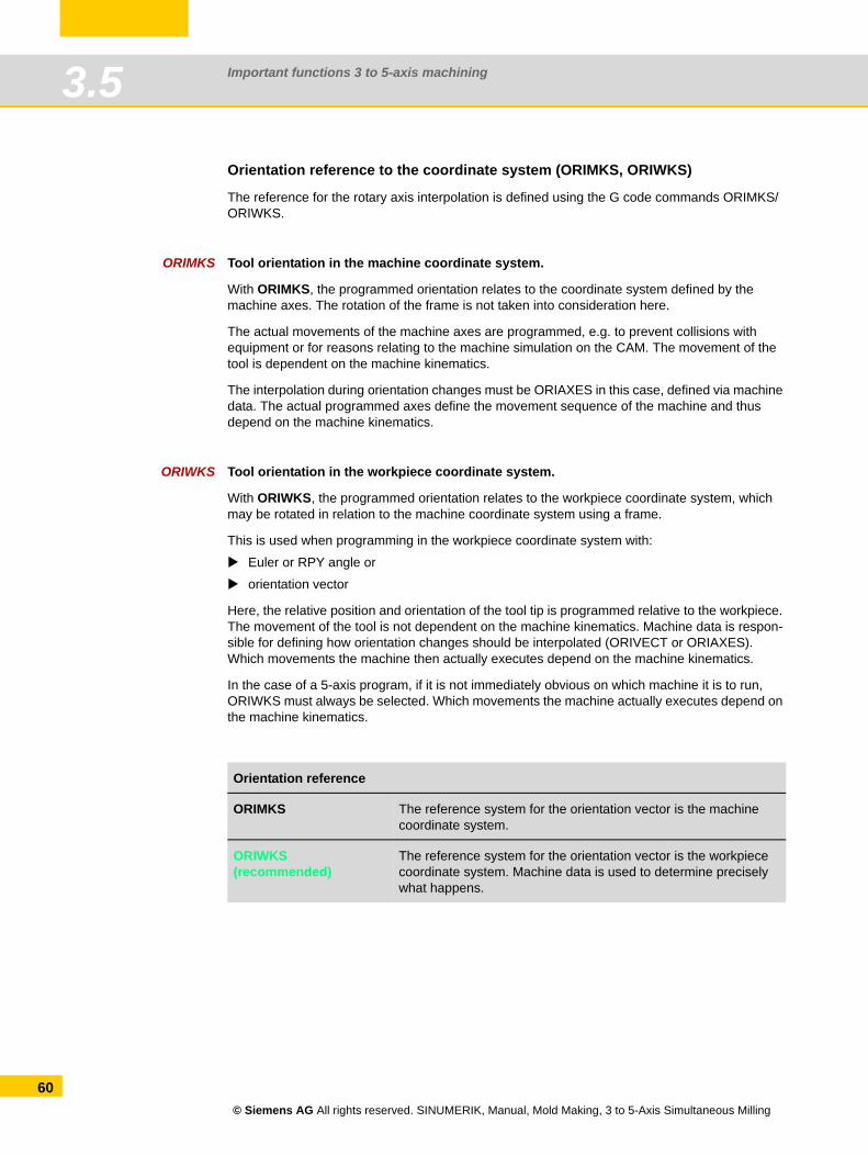
Important functions 3 to 5-axis machining3.5
60
Orientation reference to the coordinate system (ORIMKS, ORIWKS)
The reference for the rotary axis interpolation is defined using the G code commands ORIMKS/ORIWKS.
ORIMKS Tool orientation in the machine coordinate system.
With ORIMKS, the programmed orientation relates to the coordinate system defined by the machine axes. The rotation of the frame is not taken into consideration here.
The actual movements of the machine axes are programmed, e.g. to prevent collisions with equipment or for reasons relating to the machine simulation on the CAM. The movement of the tool is dependent on the machine kinematics.
The interpolation during orientation changes must be ORIAXES in this case, defined via machine data. The actual programmed axes define the movement sequence of the machine and thus depend on the machine kinematics.
ORIWKS Tool orientation in the workpiece coordinate system.
With ORIWKS, the programmed orientation relates to the workpiece coordinate system, which may be rotated in relation to the machine coordinate system using a frame.
This is used when programming in the workpiece coordinate system with:
Euler or RPY angle or
orientation vector
Here, the relative position and orientation of the tool tip is programmed relative to the workpiece. The movement of the tool is not dependent on the machine kinematics. Machine data is respon-sible for defining how orientation changes should be interpolated (ORIVECT or ORIAXES). Which movements the machine then actually executes depend on the machine kinematics.
In the case of a 5-axis program, if it is not immediately obvious on which machine it is to run, ORIWKS must always be selected. Which movements the machine actually executes depend on the machine kinematics.
Orientation reference
ORIMKS The reference system for the orientation vector is the machine coordinate system.
ORIWKS(recommended)
The reference system for the orientation vector is the workpiece coordinate system. Machine data is used to determine precisely what happens.
© Siemens AG All rights reserved. SINUMERIK, Manual, Mold Making, 3 to 5-Axis Simultaneous Milling
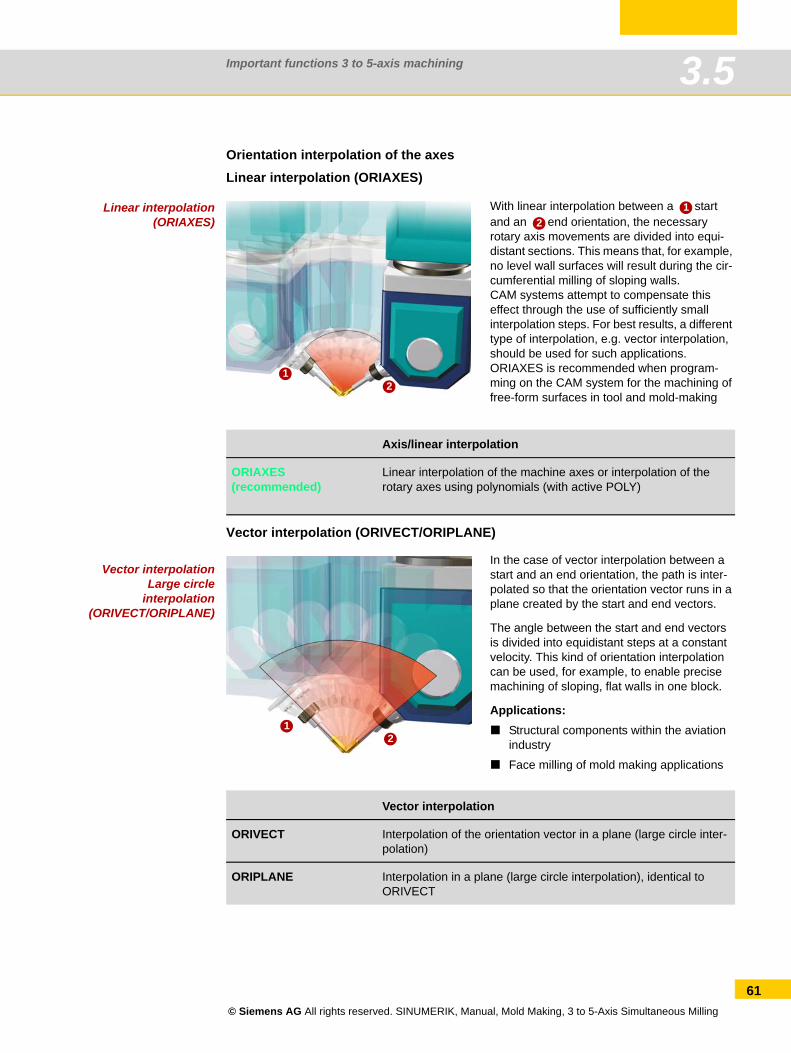
Important functions 3 to 5-axis machining 3.5
Orientation interpolation of the axesLinear interpolation (ORIAXES)
Linear interpolation(ORIAXES)
Vector interpolation (ORIVECT/ORIPLANE)
Vector interpolationLarge circle
interpolation(ORIVECT/ORIPLANE)
With linear interpolation between a start and an end orientation, the necessary rotary axis movements are divided into equi-distant sections. This means that, for example, no level wall surfaces will result during the cir-cumferential milling of sloping walls.CAM systems attempt to compensate this effect through the use of sufficiently small interpolation steps. For best results, a different type of interpolation, e.g. vector interpolation, should be used for such applications.ORIAXES is recommended when program-ming on the CAM system for the machining of free-form surfaces in tool and mold-making
Axis/linear interpolation
ORIAXES(recommended)
Linear interpolation of the machine axes or interpolation of the rotary axes using polynomials (with active POLY)
12
12
In the case of vector interpolation between a start and an end orientation, the path is inter-polated so that the orientation vector runs in a plane created by the start and end vectors.
The angle between the start and end vectors is divided into equidistant steps at a constant velocity. This kind of orientation interpolation can be used, for example, to enable precise machining of sloping, flat walls in one block.
Applications:Structural components within the aviation industry
Face milling of mold making applications
Vector interpolation
ORIVECT Interpolation of the orientation vector in a plane (large circle inter-polation)
ORIPLANE Interpolation in a plane (large circle interpolation), identical to ORIVECT
12
© Siemens AG All rights reserved. SINUMERIK, Manual, Mold Making, 3 to 5-Axis Simultaneous Milling
61
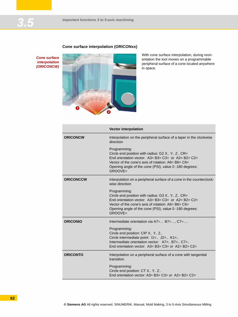
Important functions 3 to 5-axis machining3.5
62
Cone surface interpolation (ORICONxx)
Cone surfaceinterpolation
(ORICONCW)
With cone surface interpolation, during reori-entation the tool moves on a programmable peripheral surface of a cone located anywhere in space.
Vector interpolation
ORICONCW Interpolation on the peripheral surface of a taper in the clockwise direction
Programming:Circle end position with radius: G2 X.. Y.. Z.. CR=End orientation vector: A3= B3= C3= or A2= B2= C2=Vector of the cone's axis of rotation: A6= B6= C6=Opening angle of the cone (PSI), value 0 -180 degrees: GROOVE=
ORICONCCW Interpolation on a peripheral surface of a cone in the counterclock-wise direction
Programming:Circle end position with radius: G3 X.. Y.. Z.. CR=End orientation vector: A3= B3= C3= or A2= B2= C2=Vector of the cone's axis of rotation: A6= B6= C6=Opening angle of the cone (PSI), value 0 -180 degrees: GROOVE=
ORICONIO Intermediate orientation via A7=… B7=…, C7=….
Programming:Circle end position: CIP X.. Y.. Z..Circle intermediate point: I1=.. J2=.. K1=..Intermediate orientation vector: A7=.. B7=.. C7=.. End orientation vector: A3= B3= C3= or A2= B2= C2=
ORICONTO Interpolation on a peripheral surface of a cone with tangential transition.
Programming:Circle end position: CT X.. Y.. Z..End orientation vector: A3= B3= C3= or A2= B2= C2=
12
© Siemens AG All rights reserved. SINUMERIK, Manual, Mold Making, 3 to 5-Axis Simultaneous Milling
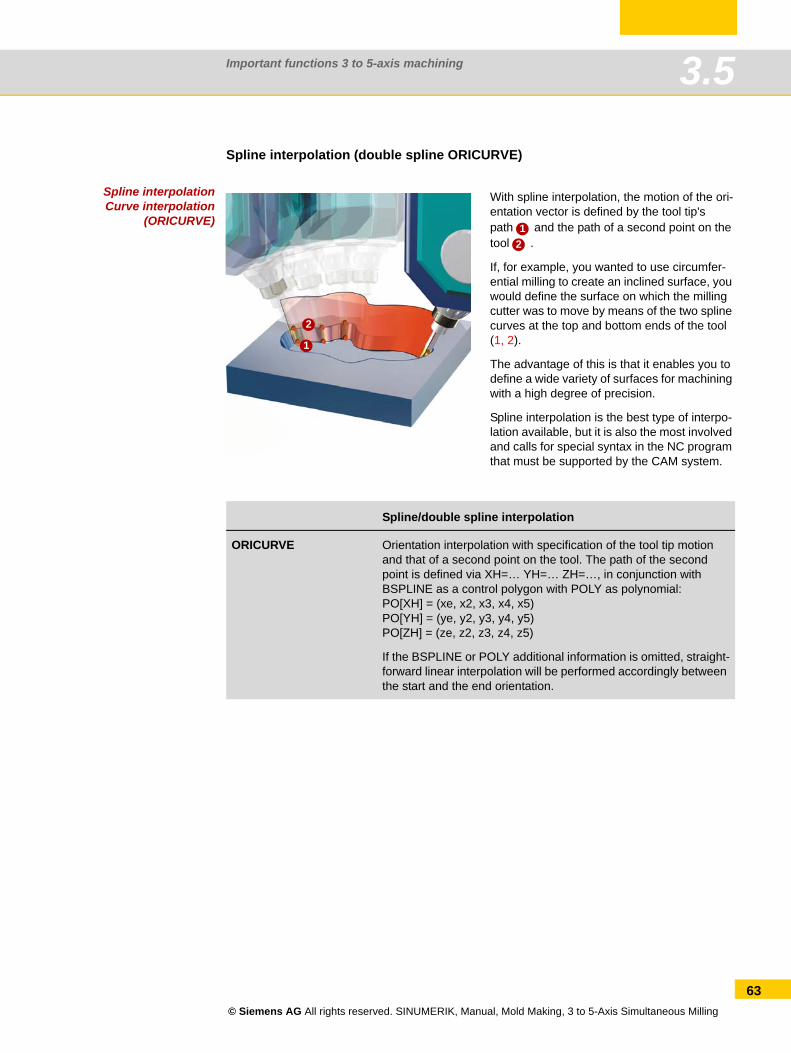
Important functions 3 to 5-axis machining 3.5
Spline interpolation (double spline ORICURVE)
Spline interpolationCurve interpolation
(ORICURVE)
With spline interpolation, the motion of the ori-entation vector is defined by the tool tip's path and the path of a second point on the tool .
If, for example, you wanted to use circumfer-ential milling to create an inclined surface, you would define the surface on which the milling cutter was to move by means of the two spline curves at the top and bottom ends of the tool (1, 2).
The advantage of this is that it enables you to define a wide variety of surfaces for machining with a high degree of precision.
Spline interpolation is the best type of interpo-lation available, but it is also the most involved and calls for special syntax in the NC program that must be supported by the CAM system.
Spline/double spline interpolation
ORICURVE Orientation interpolation with specification of the tool tip motion and that of a second point on the tool. The path of the second point is defined via XH=… YH=… ZH=…, in conjunction with BSPLINE as a control polygon with POLY as polynomial: PO[XH] = (xe, x2, x3, x4, x5)PO[YH] = (ye, y2, y3, y4, y5)PO[ZH] = (ze, z2, z3, z4, z5)
If the BSPLINE or POLY additional information is omitted, straight-forward linear interpolation will be performed accordingly between the start and the end orientation.
1
2
12
© Siemens AG All rights reserved. SINUMERIK, Manual, Mold Making, 3 to 5-Axis Simultaneous Milling
63
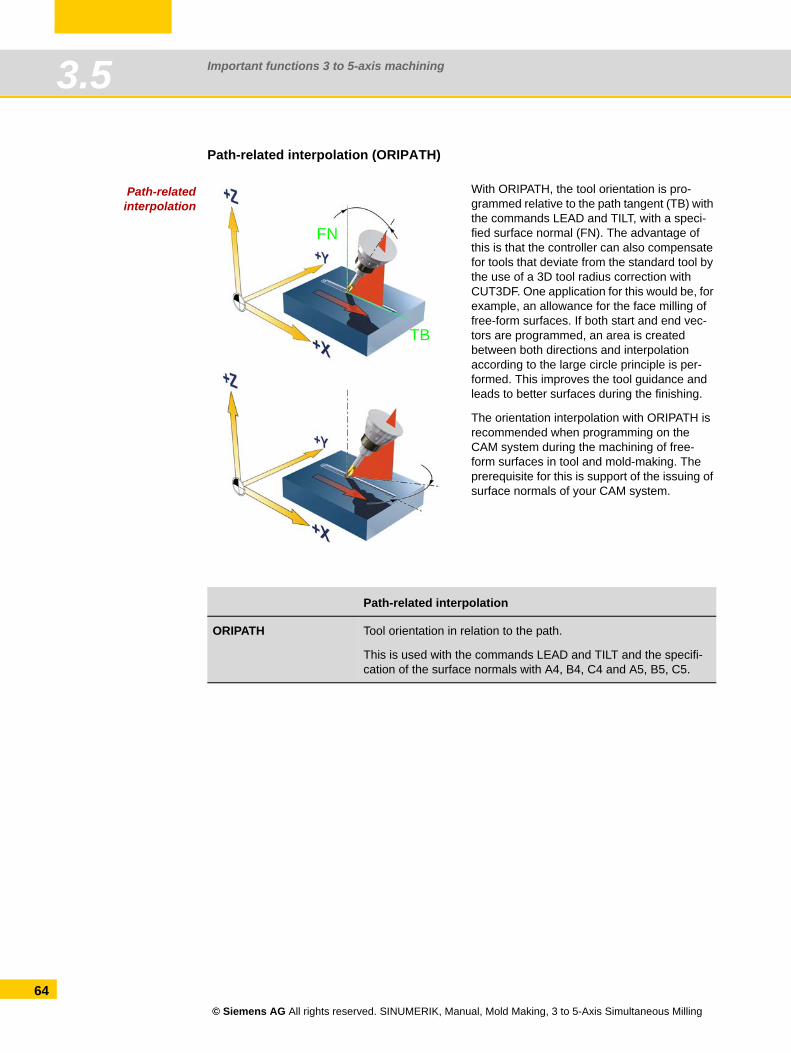
Important functions 3 to 5-axis machining3.5
64
Path-related interpolation (ORIPATH)
Path-relatedinterpolation
With ORIPATH, the tool orientation is pro-grammed relative to the path tangent (TB) with the commands LEAD and TILT, with a speci-fied surface normal (FN). The advantage of this is that the controller can also compensate for tools that deviate from the standard tool by the use of a 3D tool radius correction with CUT3DF. One application for this would be, for example, an allowance for the face milling of free-form surfaces. If both start and end vec-tors are programmed, an area is created between both directions and interpolation according to the large circle principle is per-formed. This improves the tool guidance and leads to better surfaces during the finishing.
The orientation interpolation with ORIPATH is recommended when programming on the CAM system during the machining of free-form surfaces in tool and mold-making. The prerequisite for this is support of the issuing of surface normals of your CAM system.
Path-related interpolation
ORIPATH Tool orientation in relation to the path.
This is used with the commands LEAD and TILT and the specifi-cation of the surface normals with A4, B4, C4 and A5, B5, C5.
fsfsfFN
TB
© Siemens AG All rights reserved. SINUMERIK, Manual, Mold Making, 3 to 5-Axis Simultaneous Milling
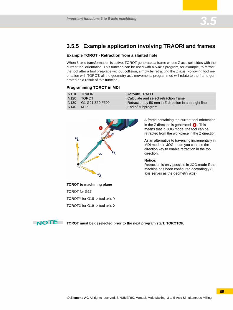
Important functions 3 to 5-axis machining 3.5
3.5.5 Example application involving TRAORI and framesExample TOROT - Retraction from a slanted hole
When 5-axis transformation is active, TOROT generates a frame whose Z axis coincides with the current tool orientation. This function can be used with a 5-axis program, for example, to retract the tool after a tool breakage without collision, simply by retracting the Z axis. Following tool ori-entation with TOROT, all the geometry axis movements programmed will relate to the frame gen-erated as a result of this function.
Programming TOROT in MDI
TOROT to machining plane
TOROT for G17
TOROTY for G18 -> tool axis Y
TOROTX for G19 -> tool axis X
TOROT must be deselected prior to the next program start: TOROTOF.
N110 TRAORI ; Activate TRAFON120 TOROT ; Calculate and select retraction frameN130 G1 G91 Z50 F500 ; Retraction by 50 mm in Z direction in a straight lineN140 M17 ; End of subprogram
A frame containing the current tool orientation in the Z direction is generated . This means that in JOG mode, the tool can be retracted from the workpiece in the Z direction.
As an alternative to traversing incrementally in MDI mode, in JOG mode you can use the direction key to enable retraction in the tool direction.
Notice:Retraction is only possible in JOG mode if the machine has been configured accordingly (Z axis serves as the geometry axis).
11
NOTE
© Siemens AG All rights reserved. SINUMERIK, Manual, Mold Making, 3 to 5-Axis Simultaneous Milling
65
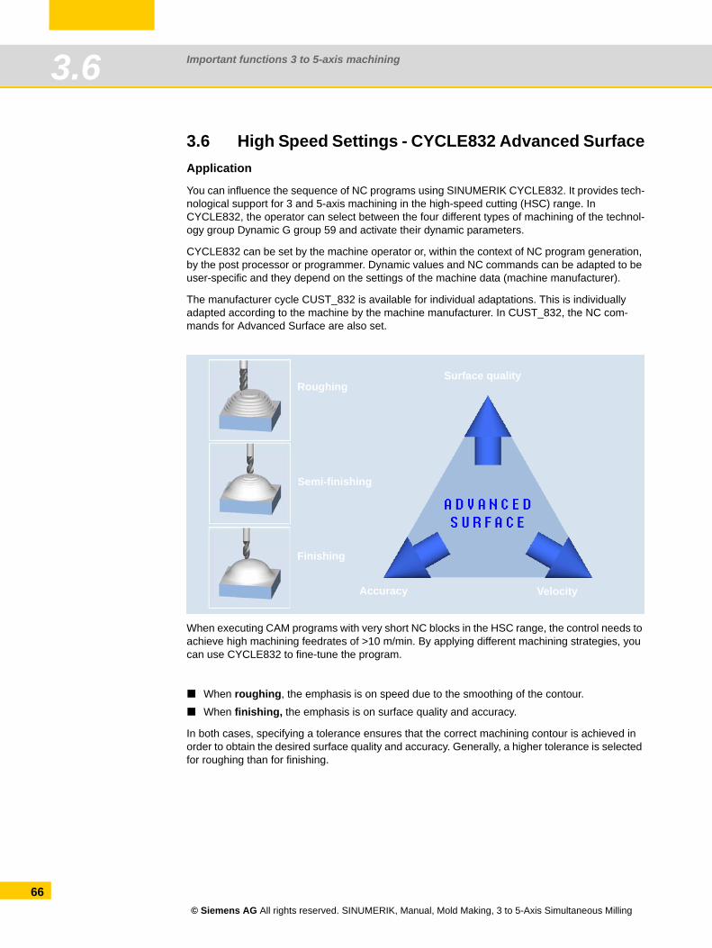
Important functions 3 to 5-axis machining3.6
66
3.6 High Speed Settings - CYCLE832 Advanced SurfaceApplication
You can influence the sequence of NC programs using SINUMERIK CYCLE832. It provides tech-nological support for 3 and 5-axis machining in the high-speed cutting (HSC) range. In CYCLE832, the operator can select between the four different types of machining of the technol-ogy group Dynamic G group 59 and activate their dynamic parameters.
CYCLE832 can be set by the machine operator or, within the context of NC program generation, by the post processor or programmer. Dynamic values and NC commands can be adapted to be user-specific and they depend on the settings of the machine data (machine manufacturer).
The manufacturer cycle CUST_832 is available for individual adaptations. This is individually adapted according to the machine by the machine manufacturer. In CUST_832, the NC com-mands for Advanced Surface are also set.
When executing CAM programs with very short NC blocks in the HSC range, the control needs to achieve high machining feedrates of >10 m/min. By applying different machining strategies, you can use CYCLE832 to fine-tune the program.
When roughing, the emphasis is on speed due to the smoothing of the contour.
When finishing, the emphasis is on surface quality and accuracy.
In both cases, specifying a tolerance ensures that the correct machining contour is achieved in order to obtain the desired surface quality and accuracy. Generally, a higher tolerance is selected for roughing than for finishing.
Surface quality
Accuracy Velocity
Roughing
Semi-finishing
Finishing
© Siemens AG All rights reserved. SINUMERIK, Manual, Mold Making, 3 to 5-Axis Simultaneous Milling
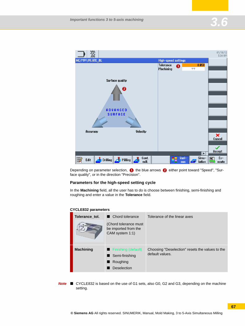
Important functions 3 to 5-axis machining 3.6
Depending on parameter selection, the blue arrows either point toward "Speed", "Sur-face quality", or in the direction "Precision".
Parameters for the high-speed setting cycle
In the Machining field, all the user has to do is choose between finishing, semi-finishing and roughing and enter a value in the Tolerance field.
CYCLE832 parameters
Note CYCLE832 is based on the use of G1 sets, also G0, G2 and G3, depending on the machine setting.
Tolerance_tol. Chord tolerance
(Chord tolerance must be imported from the CAM system 1:1)
Tolerance of the linear axes
Machining Finishing (default)
Semi-finishing
Roughing
Deselection
Choosing "Deselection" resets the values to the default values.
2
1
1 2
© Siemens AG All rights reserved. SINUMERIK, Manual, Mold Making, 3 to 5-Axis Simultaneous Milling
67
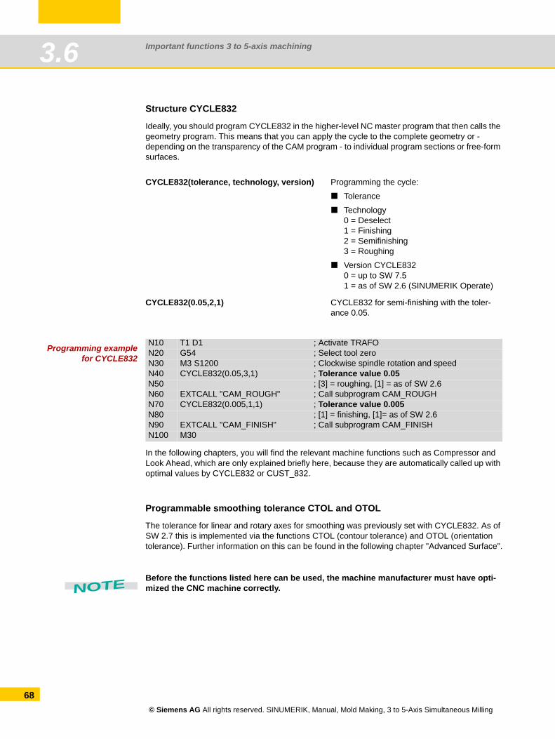
Important functions 3 to 5-axis machining3.6
68
Structure CYCLE832
Ideally, you should program CYCLE832 in the higher-level NC master program that then calls the geometry program. This means that you can apply the cycle to the complete geometry or - depending on the transparency of the CAM program - to individual program sections or free-form surfaces.
Programming examplefor CYCLE832
In the following chapters, you will find the relevant machine functions such as Compressor and Look Ahead, which are only explained briefly here, because they are automatically called up with optimal values by CYCLE832 or CUST_832.
Programmable smoothing tolerance CTOL and OTOL
The tolerance for linear and rotary axes for smoothing was previously set with CYCLE832. As of SW 2.7 this is implemented via the functions CTOL (contour tolerance) and OTOL (orientation tolerance). Further information on this can be found in the following chapter "Advanced Surface".
Before the functions listed here can be used, the machine manufacturer must have opti-mized the CNC machine correctly.
CYCLE832(tolerance, technology, version) Programming the cycle:
Tolerance
Technology0 = Deselect1 = Finishing2 = Semifinishing3 = Roughing
Version CYCLE8320 = up to SW 7.51 = as of SW 2.6 (SINUMERIK Operate)
CYCLE832(0.05,2,1) CYCLE832 for semi-finishing with the toler-ance 0.05.
N10 T1 D1 ; Activate TRAFON20 G54 ; Select tool zeroN30 M3 S1200 ; Clockwise spindle rotation and speedN40 CYCLE832(0.05,3,1) ; Tolerance value 0.05N50 ; [3] = roughing, [1] = as of SW 2.6N60 EXTCALL "CAM_ROUGH" ; Call subprogram CAM_ROUGHN70 CYCLE832(0.005,1,1) ; Tolerance value 0.005N80 ; [1] = finishing, [1]= as of SW 2.6N90 EXTCALL "CAM_FINISH" ; Call subprogram CAM_FINISHN100 M30
NOTE
© Siemens AG All rights reserved. SINUMERIK, Manual, Mold Making, 3 to 5-Axis Simultaneous Milling
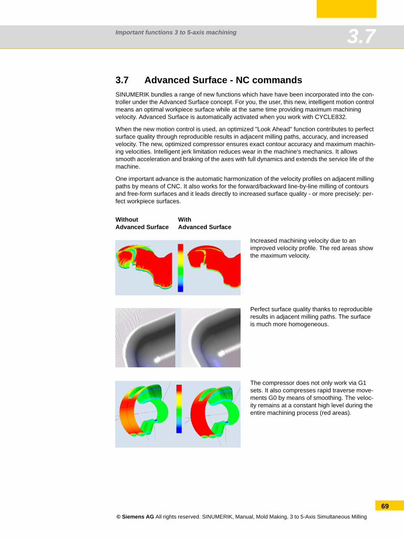
Important functions 3 to 5-axis machining 3.7
3.7 Advanced Surface - NC commandsSINUMERIK bundles a range of new functions which have have been incorporated into the con-troller under the Advanced Surface concept. For you, the user, this new, intelligent motion control means an optimal workpiece surface while at the same time providing maximum machining velocity. Advanced Surface is automatically activated when you work with CYCLE832.
When the new motion control is used, an optimized "Look Ahead" function contributes to perfect surface quality through reproducible results in adjacent milling paths, accuracy, and increased velocity. The new, optimized compressor ensures exact contour accuracy and maximum machin-ing velocities. Intelligent jerk limitation reduces wear in the machine's mechanics. It allows smooth acceleration and braking of the axes with full dynamics and extends the service life of the machine.
One important advance is the automatic harmonization of the velocity profiles on adjacent milling paths by means of CNC. It also works for the forward/backward line-by-line milling of contours and free-form surfaces and it leads directly to increased surface quality - or more precisely: per-fect workpiece surfaces.
WithoutAdvanced Surface
WithAdvanced Surface
Increased machining velocity due to an improved velocity profile. The red areas show the maximum velocity.
Perfect surface quality thanks to reproducible results in adjacent milling paths. The surface is much more homogeneous.
The compressor does not only work via G1 sets. It also compresses rapid traverse move-ments G0 by means of smoothing. The veloc-ity remains at a constant high level during the entire machining process (red areas).
© Siemens AG All rights reserved. SINUMERIK, Manual, Mold Making, 3 to 5-Axis Simultaneous Milling
69
Important functions 3 to 5-axis machining3.7
70
NC commands in connection with Advanced Surface
The following NC code commands are preset in CUST_832.SPF and are activated when the technology groups are selected in CYCLE832 in connection with the option "Advanced Surface":
DYNNORM, DYNROUGH, DYNSEMIFIN, DYNFINISH (G code group 59).
COMPCAD makes it possible to combine part programs with short linear blocks (G1), with the associated tolerance, using polynomials.
SOFT (G code group 21) activates the jerk-limited velocity control.
G645 (G code group 10) switches in the continuous path mode (Look Ahead).
FIFOCTRL (G code group 4) switches in the automatic pre-processing memory control.
FFWON (G code group 24) activates the parameterized feedforward control (speed or accel-eration feedforward control).
Important NC commands for 5-axis machining
In CUST_832.SPF, the following NC code commands can be preset by the machine manufac-turer.
TRAORI connects the 5-axis transformation set in the transformer machine data and must be programmed alone in the block.
UPATH (G code group 45) activates the path parameter, which was developed for 5-axis interpolation.
ORIAXES (G code group 51) linearly interpolates the orientation axes in the block up to the end of block.
ORIWKS (G code group 25) defines the workpiece coordinate system for orientation interpo-lation.
ORISON (G code group 61) activates the orientation smoothing for 5-axis machining with active 5-axis transformation.
© Siemens AG All rights reserved. SINUMERIK, Manual, Mold Making, 3 to 5-Axis Simultaneous Milling
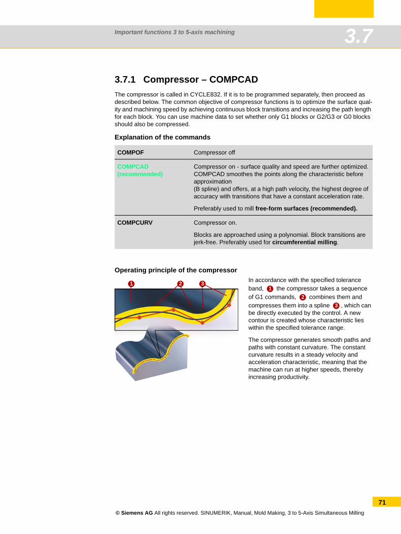
Important functions 3 to 5-axis machining 3.7
3.7.1 Compressor – COMPCADThe compressor is called in CYCLE832. If it is to be programmed separately, then proceed as described below. The common objective of compressor functions is to optimize the surface qual-ity and machining speed by achieving continuous block transitions and increasing the path length for each block. You can use machine data to set whether only G1 blocks or G2/G3 or G0 blocks should also be compressed.
Explanation of the commands
Operating principle of the compressor
COMPOF Compressor off
COMPCAD(recommended)
Compressor on - surface quality and speed are further optimized.COMPCAD smoothes the points along the characteristic before approximation (B spline) and offers, at a high path velocity, the highest degree of accuracy with transitions that have a constant acceleration rate.
Preferably used to mill free-form surfaces (recommended).
COMPCURV Compressor on.
Blocks are approached using a polynomial. Block transitions are jerk-free. Preferably used for circumferential milling.
In accordance with the specified tolerance band, the compressor takes a sequence of G1 commands, combines them and compresses them into a spline , which can be directly executed by the control. A new contour is created whose characteristic lies within the specified tolerance range.
The compressor generates smooth paths and paths with constant curvature. The constant curvature results in a steady velocity and acceleration characteristic, meaning that the machine can run at higher speeds, thereby increasing productivity.
1 2 31
23
© Siemens AG All rights reserved. SINUMERIK, Manual, Mold Making, 3 to 5-Axis Simultaneous Milling
71
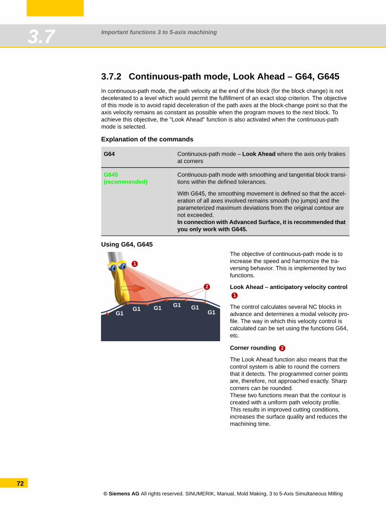
Important functions 3 to 5-axis machining3.7
72
3.7.2 Continuous-path mode, Look Ahead – G64, G645In continuous-path mode, the path velocity at the end of the block (for the block change) is not decelerated to a level which would permit the fulfillment of an exact stop criterion. The objective of this mode is to avoid rapid deceleration of the path axes at the block-change point so that the axis velocity remains as constant as possible when the program moves to the next block. To achieve this objective, the "Look Ahead" function is also activated when the continuous-path mode is selected.
Explanation of the commands
Using G64, G645
G64 Continuous-path mode – Look Ahead where the axis only brakes at corners
G645(recommended)
Continuous-path mode with smoothing and tangential block transi-tions within the defined tolerances.
With G645, the smoothing movement is defined so that the accel-eration of all axes involved remains smooth (no jumps) and the parameterized maximum deviations from the original contour are not exceeded.In connection with Advanced Surface, it is recommended that you only work with G645.
The objective of continuous-path mode is to increase the speed and harmonize the tra-versing behavior. This is implemented by two functions.
Look Ahead – anticipatory velocity control
The control calculates several NC blocks in advance and determines a modal velocity pro-file. The way in which this velocity control is calculated can be set using the functions G64, etc.
Corner rounding
The Look Ahead function also means that the control system is able to round the corners that it detects. The programmed corner points are, therefore, not approached exactly. Sharp corners can be rounded.These two functions mean that the contour is created with a uniform path velocity profile. This results in improved cutting conditions, increases the surface quality and reduces the machining time.
1
G1G1 G1 G1 G1
G1
21
2
© Siemens AG All rights reserved. SINUMERIK, Manual, Mold Making, 3 to 5-Axis Simultaneous Milling
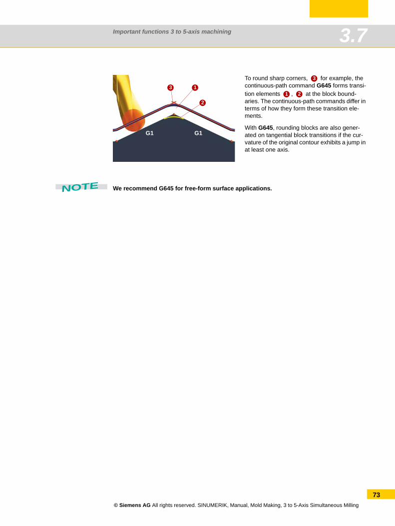
Important functions 3 to 5-axis machining 3.7
We recommend G645 for free-form surface applications.
To round sharp corners, for example, the continuous-path command G645 forms transi-tion elements , at the block bound-aries. The continuous-path commands differ in terms of how they form these transition ele-ments.
With G645, rounding blocks are also gener-ated on tangential block transitions if the cur-vature of the original contour exhibits a jump in at least one axis.
1
2
3
G1 G1
3
1 2
NOTE
© Siemens AG All rights reserved. SINUMERIK, Manual, Mold Making, 3 to 5-Axis Simultaneous Milling
73
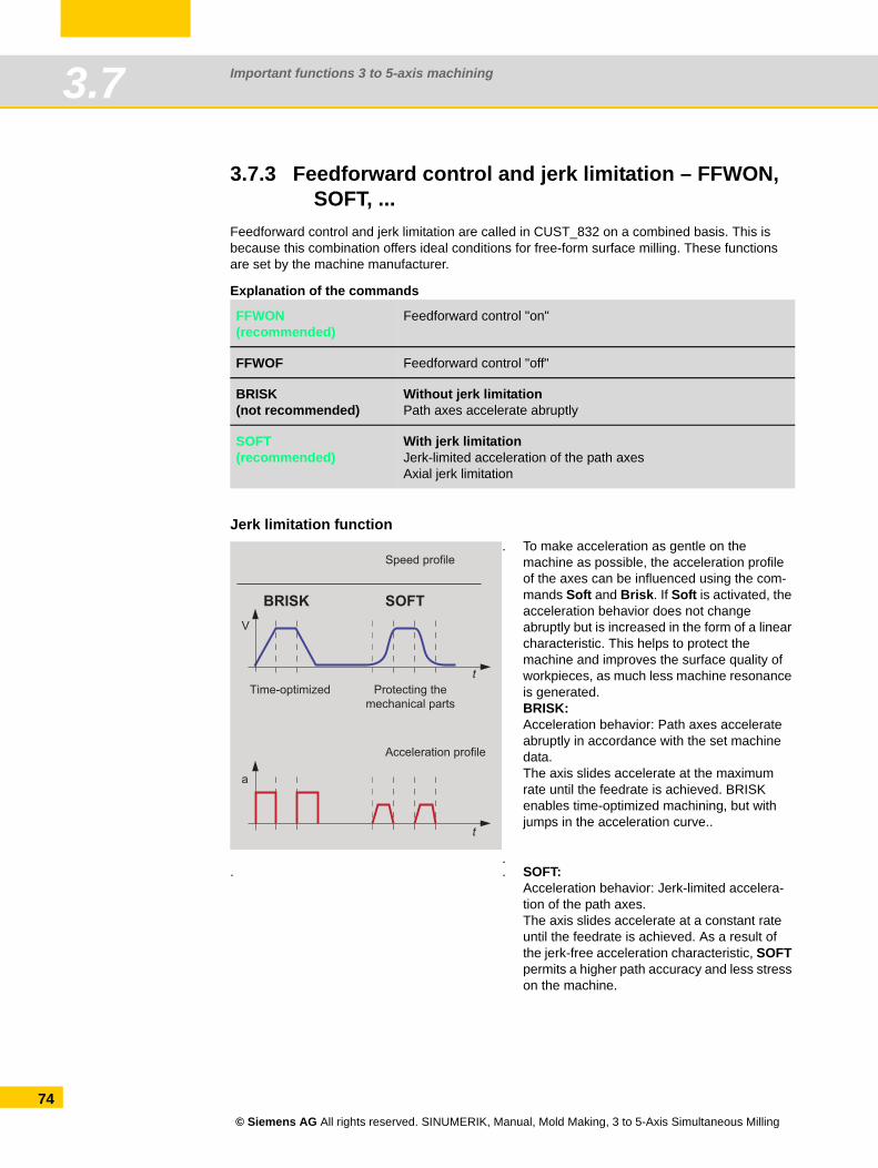
Important functions 3 to 5-axis machining3.7
74
3.7.3 Feedforward control and jerk limitation – FFWON, SOFT, ...
Feedforward control and jerk limitation are called in CUST_832 on a combined basis. This is because this combination offers ideal conditions for free-form surface milling. These functions are set by the machine manufacturer.
Explanation of the commands
Jerk limitation function
FFWON(recommended)
Feedforward control "on"
FFWOF Feedforward control "off"
BRISK(not recommended)
Without jerk limitationPath axes accelerate abruptly
SOFT(recommended)
With jerk limitationJerk-limited acceleration of the path axesAxial jerk limitation
.
. To make acceleration as gentle on the machine as possible, the acceleration profile of the axes can be influenced using the com-mands Soft and Brisk. If Soft is activated, the acceleration behavior does not change abruptly but is increased in the form of a linear characteristic. This helps to protect the machine and improves the surface quality of workpieces, as much less machine resonance is generated.BRISK:Acceleration behavior: Path axes accelerate abruptly in accordance with the set machine data.The axis slides accelerate at the maximum rate until the feedrate is achieved. BRISK enables time-optimized machining, but with jumps in the acceleration curve..
. . SOFT:Acceleration behavior: Jerk-limited accelera-tion of the path axes.The axis slides accelerate at a constant rate until the feedrate is achieved. As a result of the jerk-free acceleration characteristic, SOFT permits a higher path accuracy and less stress on the machine.
Time-optimized
BRISK
Protecting the mechanical parts
Acceleration profile
SOFT
Speed profile
t
t
V
a
© Siemens AG All rights reserved. SINUMERIK, Manual, Mold Making, 3 to 5-Axis Simultaneous Milling
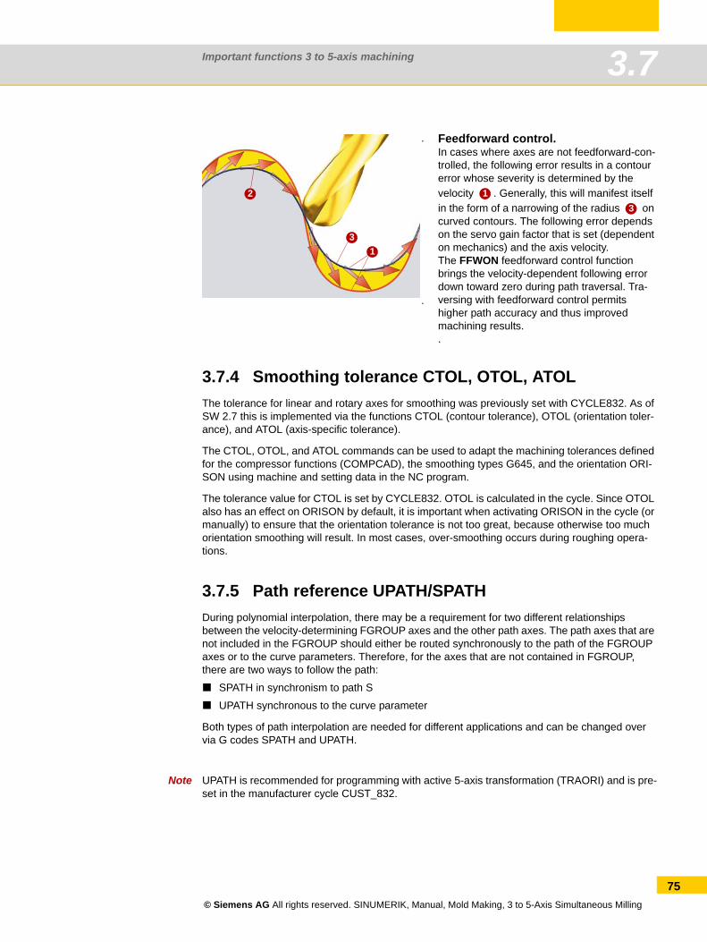
Important functions 3 to 5-axis machining 3.7
3.7.4 Smoothing tolerance CTOL, OTOL, ATOLThe tolerance for linear and rotary axes for smoothing was previously set with CYCLE832. As of SW 2.7 this is implemented via the functions CTOL (contour tolerance), OTOL (orientation toler-ance), and ATOL (axis-specific tolerance).
The CTOL, OTOL, and ATOL commands can be used to adapt the machining tolerances defined for the compressor functions (COMPCAD), the smoothing types G645, and the orientation ORI-SON using machine and setting data in the NC program.
The tolerance value for CTOL is set by CYCLE832. OTOL is calculated in the cycle. Since OTOL also has an effect on ORISON by default, it is important when activating ORISON in the cycle (or manually) to ensure that the orientation tolerance is not too great, because otherwise too much orientation smoothing will result. In most cases, over-smoothing occurs during roughing opera-tions.
3.7.5 Path reference UPATH/SPATHDuring polynomial interpolation, there may be a requirement for two different relationships between the velocity-determining FGROUP axes and the other path axes. The path axes that are not included in the FGROUP should either be routed synchronously to the path of the FGROUP axes or to the curve parameters. Therefore, for the axes that are not contained in FGROUP, there are two ways to follow the path:
SPATH in synchronism to path S
UPATH synchronous to the curve parameter
Both types of path interpolation are needed for different applications and can be changed over via G codes SPATH and UPATH.
Note UPATH is recommended for programming with active 5-axis transformation (TRAORI) and is pre-set in the manufacturer cycle CUST_832.
.
. Feedforward control. In cases where axes are not feedforward-con-trolled, the following error results in a contour error whose severity is determined by the velocity . Generally, this will manifest itself in the form of a narrowing of the radius on curved contours. The following error depends on the servo gain factor that is set (dependent on mechanics) and the axis velocity.The FFWON feedforward control function brings the velocity-dependent following error down toward zero during path traversal. Tra-versing with feedforward control permits higher path accuracy and thus improved machining results..
13
2 13
© Siemens AG All rights reserved. SINUMERIK, Manual, Mold Making, 3 to 5-Axis Simultaneous Milling
75
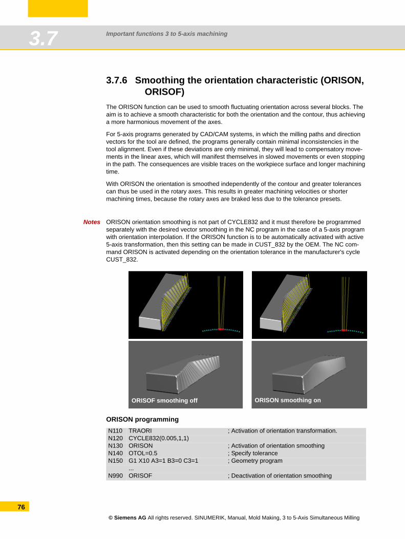
Important functions 3 to 5-axis machining3.7
76
3.7.6 Smoothing the orientation characteristic (ORISON, ORISOF)
The ORISON function can be used to smooth fluctuating orientation across several blocks. The aim is to achieve a smooth characteristic for both the orientation and the contour, thus achieving a more harmonious movement of the axes.
For 5-axis programs generated by CAD/CAM systems, in which the milling paths and direction vectors for the tool are defined, the programs generally contain minimal inconsistencies in the tool alignment. Even if these deviations are only minimal, they will lead to compensatory move-ments in the linear axes, which will manifest themselves in slowed movements or even stopping in the path. The consequences are visible traces on the workpiece surface and longer machining time.
With ORISON the orientation is smoothed independently of the contour and greater tolerances can thus be used in the rotary axes. This results in greater machining velocities or shorter machining times, because the rotary axes are braked less due to the tolerance presets.
Notes ORISON orientation smoothing is not part of CYCLE832 and it must therefore be programmed separately with the desired vector smoothing in the NC program in the case of a 5-axis program with orientation interpolation. If the ORISON function is to be automatically activated with active 5-axis transformation, then this setting can be made in CUST_832 by the OEM. The NC com-mand ORISON is activated depending on the orientation tolerance in the manufacturer's cycle CUST_832.
ORISON programmingN110 TRAORI ; Activation of orientation transformation.N120 CYCLE832(0.005,1,1)N130 ORISON ; Activation of orientation smoothingN140 OTOL=0.5 ; Specify toleranceN150 G1 X10 A3=1 B3=0 C3=1 ; Geometry program
...N990 ORISOF ; Deactivation of orientation smoothing
ORISON smoothing onORISOF smoothing off
© Siemens AG All rights reserved. SINUMERIK, Manual, Mold Making, 3 to 5-Axis Simultaneous Milling
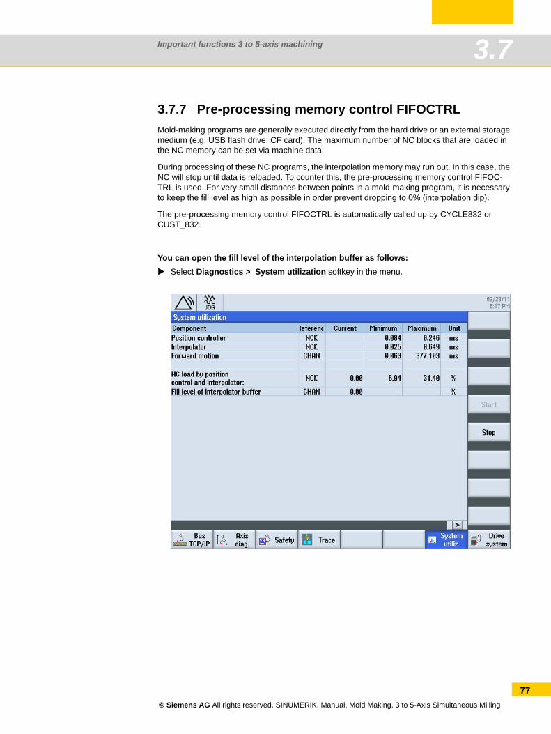
Important functions 3 to 5-axis machining 3.7
3.7.7 Pre-processing memory control FIFOCTRL Mold-making programs are generally executed directly from the hard drive or an external storage medium (e.g. USB flash drive, CF card). The maximum number of NC blocks that are loaded in the NC memory can be set via machine data.
During processing of these NC programs, the interpolation memory may run out. In this case, the NC will stop until data is reloaded. To counter this, the pre-processing memory control FIFOC-TRL is used. For very small distances between points in a mold-making program, it is necessary to keep the fill level as high as possible in order prevent dropping to 0% (interpolation dip).
The pre-processing memory control FIFOCTRL is automatically called up by CYCLE832 or CUST_832.
You can open the fill level of the interpolation buffer as follows:Select Diagnostics > System utilization softkey in the menu.
© Siemens AG All rights reserved. SINUMERIK, Manual, Mold Making, 3 to 5-Axis Simultaneous Milling
77
Important functions 3 to 5-axis machining3.7
78
3.7.8 Technology G groupsUsing the "Technology" G group, the appropriate dynamic response can be activated on the machine for five varying technological machining operations. The dynamic values and G codes are configured and set by the machine manufacturer.
Five dynamic response settings are available in the Technology G code group:DYNORM for standard dynamic response
DYNPOS for positioning mode, tapping
DYNROUGH for roughing
DYNSEMIFIN for semi-finishing
DYNFINISH for finishing
The G groups are switched and activated automatically when the machining method (e.g. finish-ing or roughing with CYCLE832 or CUST_832) is selected.
Dynamic parameters can be adapted to the respective machining operation with the technology G groups. Using the commands of technology G group 59, the value of channel and axis-specific machine data is activated using the corresponding array index. These are, for example, jerk and acceleration values.
© Siemens AG All rights reserved. SINUMERIK, Manual, Mold Making, 3 to 5-Axis Simultaneous Milling
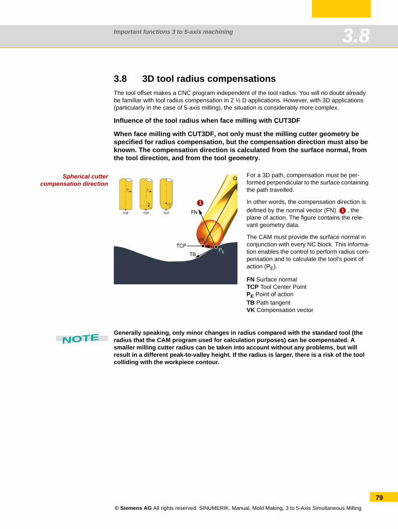
Important functions 3 to 5-axis machining 3.8
3.8 3D tool radius compensationsThe tool offset makes a CNC program independent of the tool radius. You will no doubt already be familiar with tool radius compensation in 2 ½ D applications. However, with 3D applications (particularly in the case of 5-axis milling), the situation is considerably more complex.
Influence of the tool radius when face milling with CUT3DF
When face milling with CUT3DF, not only must the milling cutter geometry be specified for radius compensation, but the compensation direction must also be known. The compensation direction is calculated from the surface normal, from the tool direction, and from the tool geometry.
Spherical cuttercompensation direction
Generally speaking, only minor changes in radius compared with the standard tool (the radius that the CAM program used for calculation purposes) can be compensated. A smaller milling cutter radius can be taken into account without any problems, but will result in a different peak-to-valley height. If the radius is larger, there is a risk of the tool colliding with the workpiece contour.
For a 3D path, compensation must be per-formed perpendicular to the surface containing the path travelled.
In other words, the compensation direction is defined by the normal vector (FN) , the plane of action. The figure contains the rele-vant geometry data.
The CAM must provide the surface normal in conjunction with every NC block. This informa-tion enables the control to perform radius com-pensation and to calculate the tool's point of action (PE).
FN Surface normalTCP Tool Center PointPE Point of actionTB Path tangentVK Compensation vector
11
NOTE
© Siemens AG All rights reserved. SINUMERIK, Manual, Mold Making, 3 to 5-Axis Simultaneous Milling
79
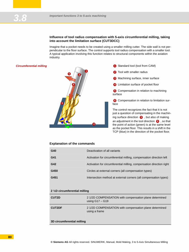
Important functions 3 to 5-axis machining3.8
80
Influence of tool radius compensation with 5-axis circumferential milling, taking into account the limitation surface (CUT3DCC)
Imagine that a pocket needs to be created using a smaller milling cutter. The side wall is not per-pendicular to the floor surface. The control supports tool radius compensation with a smaller tool. A typical application involving this function relates to structural components within the aviation industry.
Circumferential milling
Explanation of the commands
Standard tool (tool from CAM)
Tool with smaller radius
Machining surface, inner surface
Limitation surface of pocket floor
Compensation in relation to machining surface
Compensation in relation to limitation sur-face
The control recognizes the fact that it is not just a question of compensating in the machin-ing surface direction , but also of making an adjustment in the tool direction , so that the point of action (green) is at the same level as the pocket floor. This results in a shift in the TCP (blue) in the direction of the pocket floor.
G40 Deactivation of all variants
G41 Activation for circumferential milling, compensation direction left
G42 Activation for circumferential milling, compensation direction right
G450 Circles at external corners (all compensation types)
G451 Intersection method at external corners (all compensation types)
2 ½D circumferential milling
CUT2D 2 1/2D COMPENSATION with compensation plane determined using G17 – G19
CUT2DF 2 1/2D COMPENSATION with compensation plane determined using a frame
3D circumferential milling
12
3
5
6
4
1
2
3
4
5
6
56
© Siemens AG All rights reserved. SINUMERIK, Manual, Mold Making, 3 to 5-Axis Simultaneous Milling
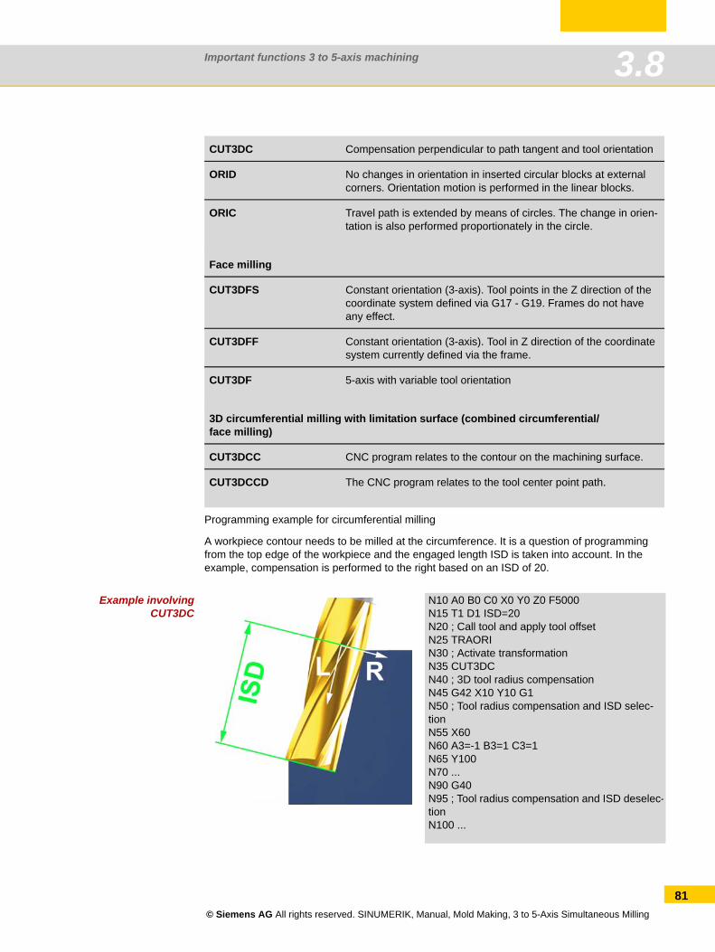
Important functions 3 to 5-axis machining 3.8
Programming example for circumferential milling
A workpiece contour needs to be milled at the circumference. It is a question of programming from the top edge of the workpiece and the engaged length ISD is taken into account. In the example, compensation is performed to the right based on an ISD of 20.
Example involvingCUT3DC
CUT3DC Compensation perpendicular to path tangent and tool orientation
ORID No changes in orientation in inserted circular blocks at external corners. Orientation motion is performed in the linear blocks.
ORIC Travel path is extended by means of circles. The change in orien-tation is also performed proportionately in the circle.
Face milling
CUT3DFS Constant orientation (3-axis). Tool points in the Z direction of the coordinate system defined via G17 - G19. Frames do not have any effect.
CUT3DFF Constant orientation (3-axis). Tool in Z direction of the coordinate system currently defined via the frame.
CUT3DF 5-axis with variable tool orientation
3D circumferential milling with limitation surface (combined circumferential/face milling)
CUT3DCC CNC program relates to the contour on the machining surface.
CUT3DCCD The CNC program relates to the tool center point path.
N10 A0 B0 C0 X0 Y0 Z0 F5000N15 T1 D1 ISD=20N20 ; Call tool and apply tool offsetN25 TRAORIN30 ; Activate transformationN35 CUT3DCN40 ; 3D tool radius compensationN45 G42 X10 Y10 G1N50 ; Tool radius compensation and ISD selec-tionN55 X60N60 A3=-1 B3=1 C3=1N65 Y100N70 ...N90 G40N95 ; Tool radius compensation and ISD deselec-tionN100 ...
© Siemens AG All rights reserved. SINUMERIK, Manual, Mold Making, 3 to 5-Axis Simultaneous Milling
81
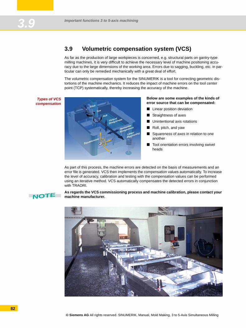
Important functions 3 to 5-axis machining3.9
82
3.9 Volumetric compensation system (VCS)As far as the production of large workpieces is concerned, e.g. structural parts on gantry-type milling machines, it is very difficult to achieve the necessary level of machine positioning accu-racy due to the large dimensions of the working area. Errors due to sagging, buckling, etc. in par-ticular can only be remedied mechanically with a great deal of effort.
The volumetric compensation system for the SINUMERIK is a tool for correcting geometric dis-tortions of the machine mechanics. It reduces the impact of machine errors on the tool center point (TCP) systematically, thereby increasing the accuracy of the machine.
Types of VCScompensation
As part of this process, the machine errors are detected on the basis of measurements and an error file is generated. VCS then implements the compensation values automatically. To increase the level of accuracy, calibration and testing with the compensation values can be performed using an iterative method. VCS automatically compensates the detected errors in conjunction with TRAORI.
As regards the VCS commissioning process and machine calibration, please contact your machine manufacturer.
Below are some examples of the kinds of error source that can be compensated:
Linear position deviation
Straightness of axes
Unintentional axis rotations
Roll, pitch, and yaw
Squareness of axes in relation to one another
Tool orientation errors involving swivel heads
NOTE
© Siemens AG All rights reserved. SINUMERIK, Manual, Mold Making, 3 to 5-Axis Simultaneous Milling
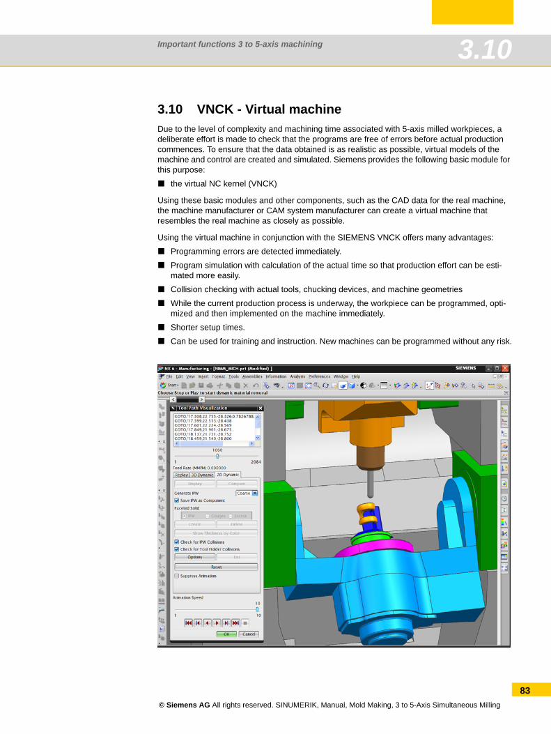
Important functions 3 to 5-axis machining 3.10
3.10 VNCK - Virtual machineDue to the level of complexity and machining time associated with 5-axis milled workpieces, a deliberate effort is made to check that the programs are free of errors before actual production commences. To ensure that the data obtained is as realistic as possible, virtual models of the machine and control are created and simulated. Siemens provides the following basic module for this purpose:
the virtual NC kernel (VNCK)
Using these basic modules and other components, such as the CAD data for the real machine, the machine manufacturer or CAM system manufacturer can create a virtual machine that resembles the real machine as closely as possible.
Using the virtual machine in conjunction with the SIEMENS VNCK offers many advantages:
Programming errors are detected immediately.
Program simulation with calculation of the actual time so that production effort can be esti-mated more easily.
Collision checking with actual tools, chucking devices, and machine geometries
While the current production process is underway, the workpiece can be programmed, opti-mized and then implemented on the machine immediately.
Shorter setup times.
Can be used for training and instruction. New machines can be programmed without any risk.
© Siemens AG All rights reserved. SINUMERIK, Manual, Mold Making, 3 to 5-Axis Simultaneous Milling
83
Important functions 3 to 5-axis machining3.10
84
© Siemens AG All rights reserved. SINUMERIK, Manual, Mold Making, 3 to 5-Axis Simultaneous Milling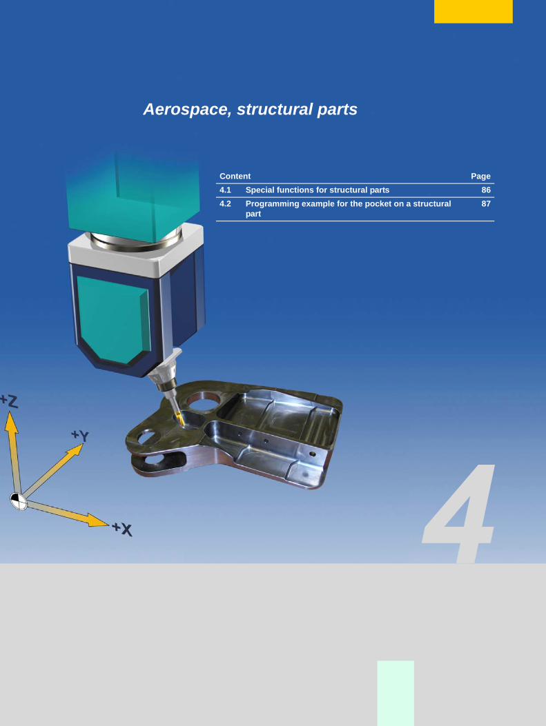
Aerospace, structural parts
Content Page4.1 Special functions for structural parts 864.2 Programming example for the pocket on a structural
part87
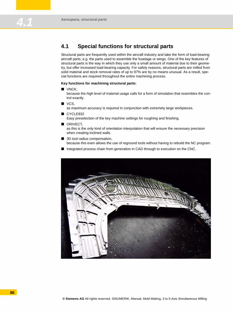
Aerospace, structural parts4.1
86
4.1 Special functions for structural partsStructural parts are frequently used within the aircraft industry and take the form of load-bearing aircraft parts, e.g. the parts used to assemble the fuselage or wings. One of the key features of structural parts is the way in which they use only a small amount of material due to their geome-try, but offer increased load-bearing capacity. For safety reasons, structural parts are milled from solid material and stock removal rates of up to 97% are by no means unusual. As a result, spe-cial functions are required throughout the entire machining process.
Key functions for machining structural parts:VNCK,because the high level of material usage calls for a form of simulation that resembles the con-trol exactly.
VCS,as maximum accuracy is required in conjunction with extremely large workpieces.
CYCLE832Easy preselection of the key machine settings for roughing and finishing.
ORIVECT,as this is the only kind of orientation interpolation that will ensure the necessary precision when creating inclined walls.
3D tool radius compensation,because this even allows the use of reground tools without having to rebuild the NC program.
Integrated process chain from generation in CAD through to execution on the CNC.
© Siemens AG All rights reserved. SINUMERIK, Manual, Mold Making, 3 to 5-Axis Simultaneous Milling
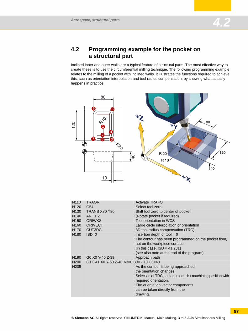
Aerospace, structural parts 4.2
4.2 Programming example for the pocket ona structural part
Inclined inner and outer walls are a typical feature of structural parts. The most effective way to create these is to use the circumferential milling technique. The following programming example relates to the milling of a pocket with inclined walls. It illustrates the functions required to achieve this, such as orientation interpolation and tool radius compensation, by showing what actually happens in practice.
N110 TRAORI ; Activate TRAFON120 G54 ; Select tool zeroN130 TRANS X80 Y80 ; Shift tool zero to center of pocket!N140 AROT Z ; (Rotate pocket if required)N150 ORIWKS ; Tool orientation in WCSN160 ORIVECT ; Large circle interpolation of orientationN170 CUT3DC ; 3D tool radius compensation (TRC)N180 ISD=0 ; Insertion depth of tool = 0
; The contour has been programmed on the pocket floor,; not on the workpiece surface; (in this case, ISD = 41.231); (see also note at the end of the program)
N190 G0 X0 Y-40 Z-39 ; Approach pathN200 G1 G41 X0 Y-50 Z-40 A3=0 B3= - 10 C3=40N205 ; As the contour is being approached,
; the orientation changes.; Selection of TRC and approach 1st machining position with; required orientation.; The orientation vector components; can be taken directly from the; drawing.
1
23
4
56
7 8
© Siemens AG All rights reserved. SINUMERIK, Manual, Mold Making, 3 to 5-Axis Simultaneous Milling
87
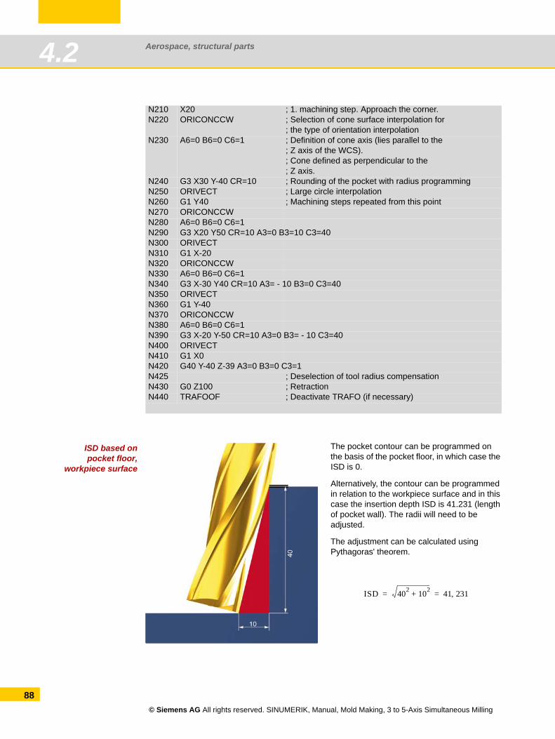
Aerospace, structural parts4.2
88
ISD based onpocket floor,
workpiece surface
N210 X20 ; 1. machining step. Approach the corner.N220 ORICONCCW ; Selection of cone surface interpolation for
; the type of orientation interpolationN230 A6=0 B6=0 C6=1 ; Definition of cone axis (lies parallel to the
; Z axis of the WCS).; Cone defined as perpendicular to the; Z axis.
N240 G3 X30 Y-40 CR=10 ; Rounding of the pocket with radius programmingN250 ORIVECT ; Large circle interpolationN260 G1 Y40 ; Machining steps repeated from this pointN270 ORICONCCWN280 A6=0 B6=0 C6=1N290 G3 X20 Y50 CR=10 A3=0 B3=10 C3=40N300 ORIVECTN310 G1 X-20N320 ORICONCCWN330 A6=0 B6=0 C6=1N340 G3 X-30 Y40 CR=10 A3= - 10 B3=0 C3=40N350 ORIVECTN360 G1 Y-40N370 ORICONCCWN380 A6=0 B6=0 C6=1N390 G3 X-20 Y-50 CR=10 A3=0 B3= - 10 C3=40N400 ORIVECTN410 G1 X0N420 G40 Y-40 Z-39 A3=0 B3=0 C3=1N425 ; Deselection of tool radius compensationN430 G0 Z100 ; RetractionN440 TRAFOOF ; Deactivate TRAFO (if necessary)
The pocket contour can be programmed on the basis of the pocket floor, in which case the ISD is 0.
Alternatively, the contour can be programmed in relation to the workpiece surface and in this case the insertion depth ISD is 41.231 (length of pocket wall). The radii will need to be adjusted.
The adjustment can be calculated using Pythagoras' theorem.
ISD 402 102+ 41 231,= =
© Siemens AG All rights reserved. SINUMERIK, Manual, Mold Making, 3 to 5-Axis Simultaneous Milling
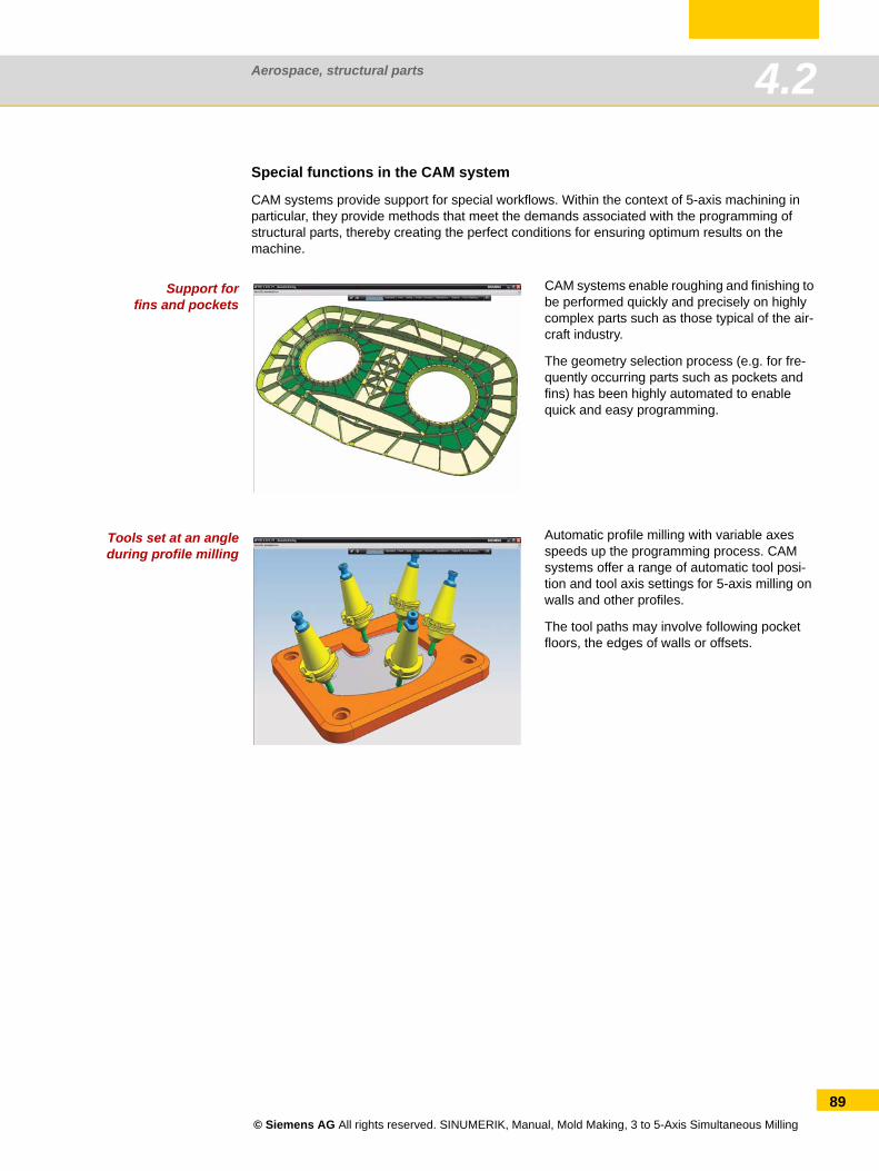
Aerospace, structural parts 4.2
Special functions in the CAM system
CAM systems provide support for special workflows. Within the context of 5-axis machining in particular, they provide methods that meet the demands associated with the programming of structural parts, thereby creating the perfect conditions for ensuring optimum results on the machine.
Support forfins and pockets
Tools set at an angleduring profile milling
CAM systems enable roughing and finishing to be performed quickly and precisely on highly complex parts such as those typical of the air-craft industry.
The geometry selection process (e.g. for fre-quently occurring parts such as pockets and fins) has been highly automated to enable quick and easy programming.
Automatic profile milling with variable axes speeds up the programming process. CAM systems offer a range of automatic tool posi-tion and tool axis settings for 5-axis milling on walls and other profiles.
The tool paths may involve following pocket floors, the edges of walls or offsets.
© Siemens AG All rights reserved. SINUMERIK, Manual, Mold Making, 3 to 5-Axis Simultaneous Milling
89
Aerospace, structural parts4.2
90
© Siemens AG All rights reserved. SINUMERIK, Manual, Mold Making, 3 to 5-Axis Simultaneous Milling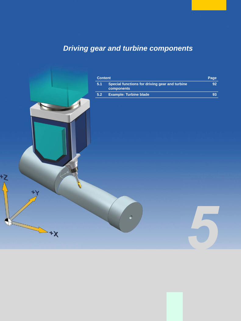
Driving gear and turbine components
Content Page5.1 Special functions for driving gear and turbine
components92
5.2 Example: Turbine blade 93
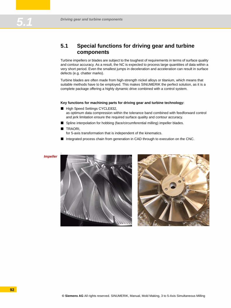
Driving gear and turbine components5.1
92
5.1 Special functions for driving gear and turbinecomponents
Turbine impellers or blades are subject to the toughest of requirements in terms of surface quality and contour accuracy. As a result, the NC is expected to process large quantities of data within a very short period. Even the smallest jumps in deceleration and acceleration can result in surface defects (e.g. chatter marks).
Turbine blades are often made from high-strength nickel alloys or titanium, which means that suitable methods have to be employed. This makes SINUMERIK the perfect solution, as it is a complete package offering a highly dynamic drive combined with a control system.
Key functions for machining parts for driving gear and turbine technology:High Speed Settings CYCLE832,as optimum data compression within the tolerance band combined with feedforward control and jerk limitation ensure the required surface quality and contour accuracy.
Spline interpolation for hobbing (face/circumferential milling) impeller blades.
TRAORI,for 5-axis transformation that is independent of the kinematics.
Integrated process chain from generation in CAD through to execution on the CNC.
Impeller.
© Siemens AG All rights reserved. SINUMERIK, Manual, Mold Making, 3 to 5-Axis Simultaneous Milling
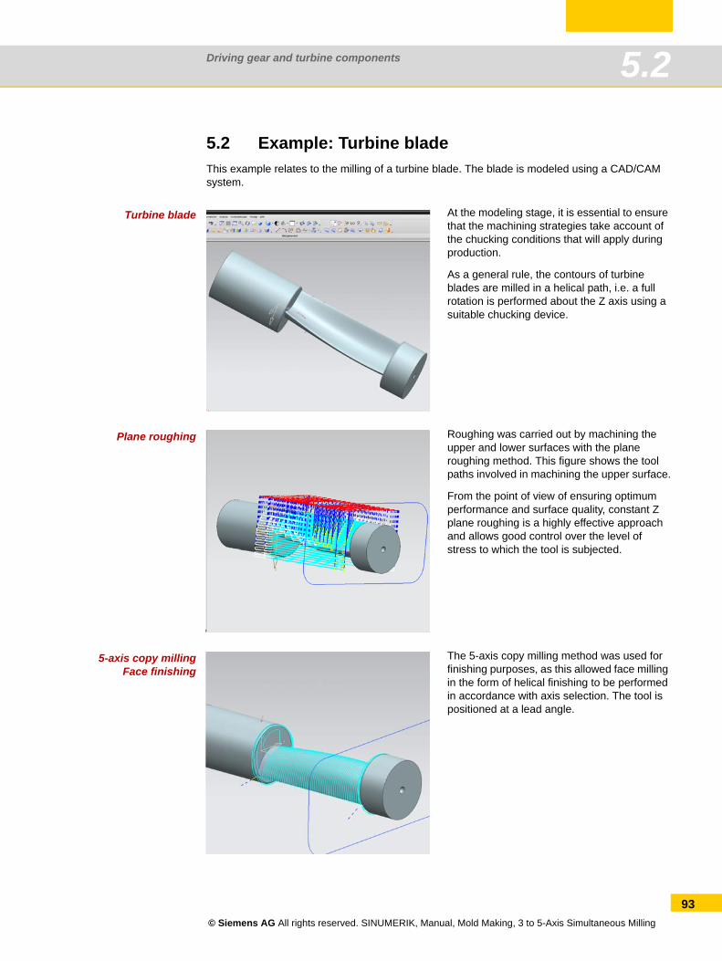
Driving gear and turbine components 5.2
5.2 Example: Turbine bladeThis example relates to the milling of a turbine blade. The blade is modeled using a CAD/CAM system.
Turbine blade
Plane roughing
5-axis copy millingFace finishing
At the modeling stage, it is essential to ensure that the machining strategies take account of the chucking conditions that will apply during production.
As a general rule, the contours of turbine blades are milled in a helical path, i.e. a full rotation is performed about the Z axis using a suitable chucking device.
Roughing was carried out by machining the upper and lower surfaces with the plane roughing method. This figure shows the tool paths involved in machining the upper surface.
From the point of view of ensuring optimum performance and surface quality, constant Z plane roughing is a highly effective approach and allows good control over the level of stress to which the tool is subjected.
The 5-axis copy milling method was used for finishing purposes, as this allowed face milling in the form of helical finishing to be performed in accordance with axis selection. The tool is positioned at a lead angle.
© Siemens AG All rights reserved. SINUMERIK, Manual, Mold Making, 3 to 5-Axis Simultaneous Milling
93
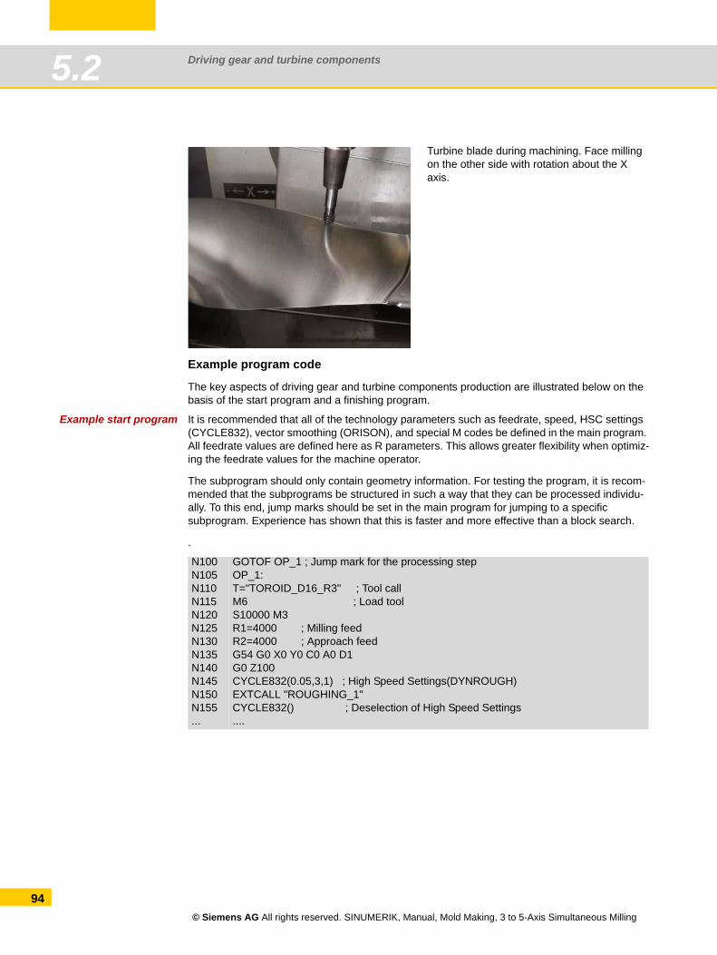
Driving gear and turbine components5.2
94
Example program code
The key aspects of driving gear and turbine components production are illustrated below on the basis of the start program and a finishing program.
Example start program It is recommended that all of the technology parameters such as feedrate, speed, HSC settings (CYCLE832), vector smoothing (ORISON), and special M codes be defined in the main program. All feedrate values are defined here as R parameters. This allows greater flexibility when optimiz-ing the feedrate values for the machine operator.
The subprogram should only contain geometry information. For testing the program, it is recom-mended that the subprograms be structured in such a way that they can be processed individu-ally. To this end, jump marks should be set in the main program for jumping to a specific subprogram. Experience has shown that this is faster and more effective than a block search.
.
Turbine blade during machining. Face milling on the other side with rotation about the X axis.
N100N105N110N115N120N125N130N135N140N145N150N155...
GOTOF OP_1 ; Jump mark for the processing stepOP_1:T="TOROID_D16_R3" ; Tool callM6 ; Load toolS10000 M3R1=4000 ; Milling feedR2=4000 ; Approach feedG54 G0 X0 Y0 C0 A0 D1G0 Z100CYCLE832(0.05,3,1) ; High Speed Settings(DYNROUGH)EXTCALL "ROUGHING_1"CYCLE832() ; Deselection of High Speed Settings....
© Siemens AG All rights reserved. SINUMERIK, Manual, Mold Making, 3 to 5-Axis Simultaneous Milling
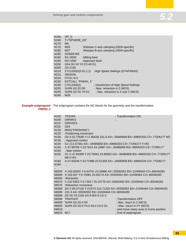
Driving gear and turbine components 5.2
Example subprogram FINISH_1
The subprogram contains the NC blocks for the geometry and the transformation.
N160N165N170N175N180N185N190N195N200N205N210N215N220N225N230N235N240N245
OP_5:T="SPHERE_D6"M6M25 ;Release C-axis clamping (OEM-specific)M27 ;Release B-axis clamping (OEM-specific)S15000 M3R1=2000 ;Milling feedR2=1000 ;Approach feedG54 G0 X0 Y0 C0 A0 D1G0 Z100CYCLE832(0.01,1,1) ;High Speed Settings (DYNFINISH)ORISONOTOL=0.5EXTCALL "FINISH_1"CYCLE832() ; Deselection of High Speed SettingsSUPA G0 Z0 D0 ; Max. retraction in Z (MCS)SUPA G0 X0 Y0 D1 ; Max. retraction in X and Y (MCS)M30
N100N105N110N115N120N125N130N135N140N145N150N155
N160N165...
TRAORI ; Transformation ONORIWKS ; ORIAXESG54MSG("FINISHING");Positioning movementG0 X-52.73538 Y-17.80536 Z31.9 A3=-.39485858 B3=.49800333 C3=.77206177 M3; Approach motionG1 Z13.37361 A3=-.39485858 B3=.49800333 C3=.77206177 F=R2X-47.99708 Y-23.7814 Z4.10887 A3=-.39485858 B3=.49800333 C3=.77206177; Start motionG1 X-47.84399 Y-23.76942 Z3.80953 A3=-.39485858 B3=.49800333 C3=.77206177 M8 F=R1X-47.69248 Y-23.71986 Z3.51328 A3=-.39485858 B3=.49800333 C3=.77206177...
N6555N6560N6565N6570N6575N6580N6585N6590N6595N6600N6605N6610N6615
X-103.02652 Y-5.64791 Z4.55886 A3=.55592652 B3=.22406464 C3=.80046283X-102.837 Y-5.70081 Z4.83174 A3=.55592652 B3=.22406464 C3=.80046283;Retraction X-102.6453 Y-5.71617 Z5.10778 A3=.55592652 B3=.22406464 C3=.80046283;Retraction movementG0 X-95.97418 Y-3.0274 Z14.71333 A3=.55592652 B3=.22406464 C3=.80046283Z31.9 A3=.55592652 B3=.22406464 C3=.80046283G0 X0 Y0 Z100 A3=0 B3=0 C3=1 TRAFOOF ; Transformation OFFSUPA G0 Z0.0 D0 ; Max. return in Z (MCS)SUPA G0 X0.0 Y0.0 A0.0 C0.0 D1 ; Max. return in XY (MCS) ; and move rotary axes to home positionM17 ; End of subprogram
© Siemens AG All rights reserved. SINUMERIK, Manual, Mold Making, 3 to 5-Axis Simultaneous Milling
95

Driving gear and turbine components5.2
96
© Siemens AG All rights reserved. SINUMERIK, Manual, Mold Making, 3 to 5-Axis Simultaneous Milling
Complex free-form surfaces
Content Page6.1 Special functions for free-form surfaces 986.2 Example: Milling a manta ray 99
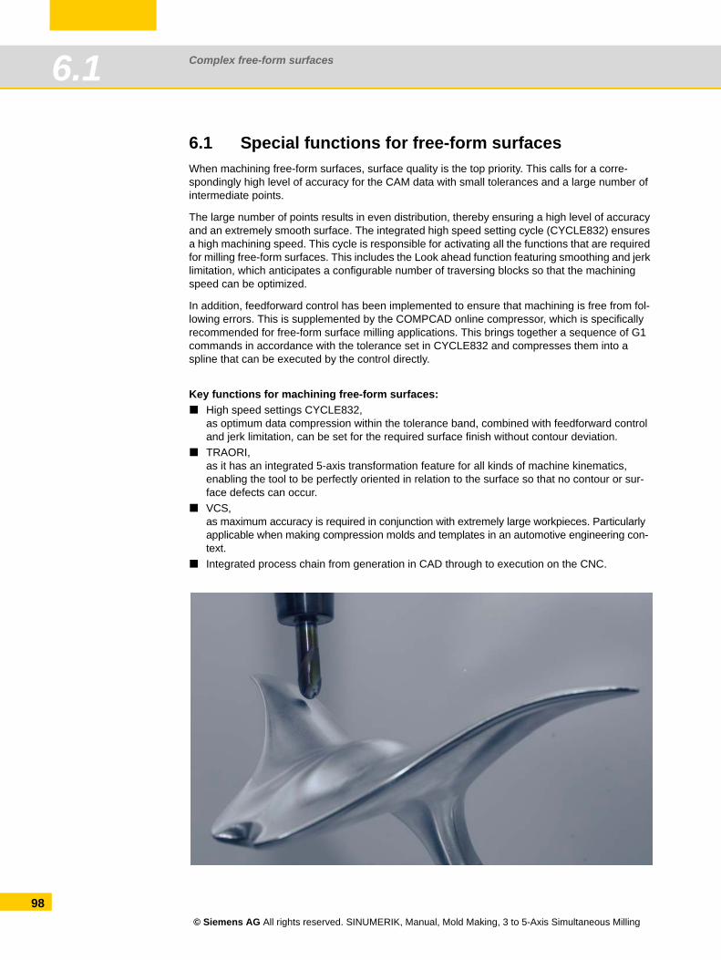
Complex free-form surfaces6.1
98
6.1 Special functions for free-form surfacesWhen machining free-form surfaces, surface quality is the top priority. This calls for a corre-spondingly high level of accuracy for the CAM data with small tolerances and a large number of intermediate points.
The large number of points results in even distribution, thereby ensuring a high level of accuracy and an extremely smooth surface. The integrated high speed setting cycle (CYCLE832) ensures a high machining speed. This cycle is responsible for activating all the functions that are required for milling free-form surfaces. This includes the Look ahead function featuring smoothing and jerk limitation, which anticipates a configurable number of traversing blocks so that the machining speed can be optimized.
In addition, feedforward control has been implemented to ensure that machining is free from fol-lowing errors. This is supplemented by the COMPCAD online compressor, which is specifically recommended for free-form surface milling applications. This brings together a sequence of G1 commands in accordance with the tolerance set in CYCLE832 and compresses them into a spline that can be executed by the control directly.
Key functions for machining free-form surfaces:High speed settings CYCLE832,as optimum data compression within the tolerance band, combined with feedforward control and jerk limitation, can be set for the required surface finish without contour deviation.TRAORI,as it has an integrated 5-axis transformation feature for all kinds of machine kinematics, enabling the tool to be perfectly oriented in relation to the surface so that no contour or sur-face defects can occur.VCS,as maximum accuracy is required in conjunction with extremely large workpieces. Particularly applicable when making compression molds and templates in an automotive engineering con-text.Integrated process chain from generation in CAD through to execution on the CNC.
© Siemens AG All rights reserved. SINUMERIK, Manual, Mold Making, 3 to 5-Axis Simultaneous Milling
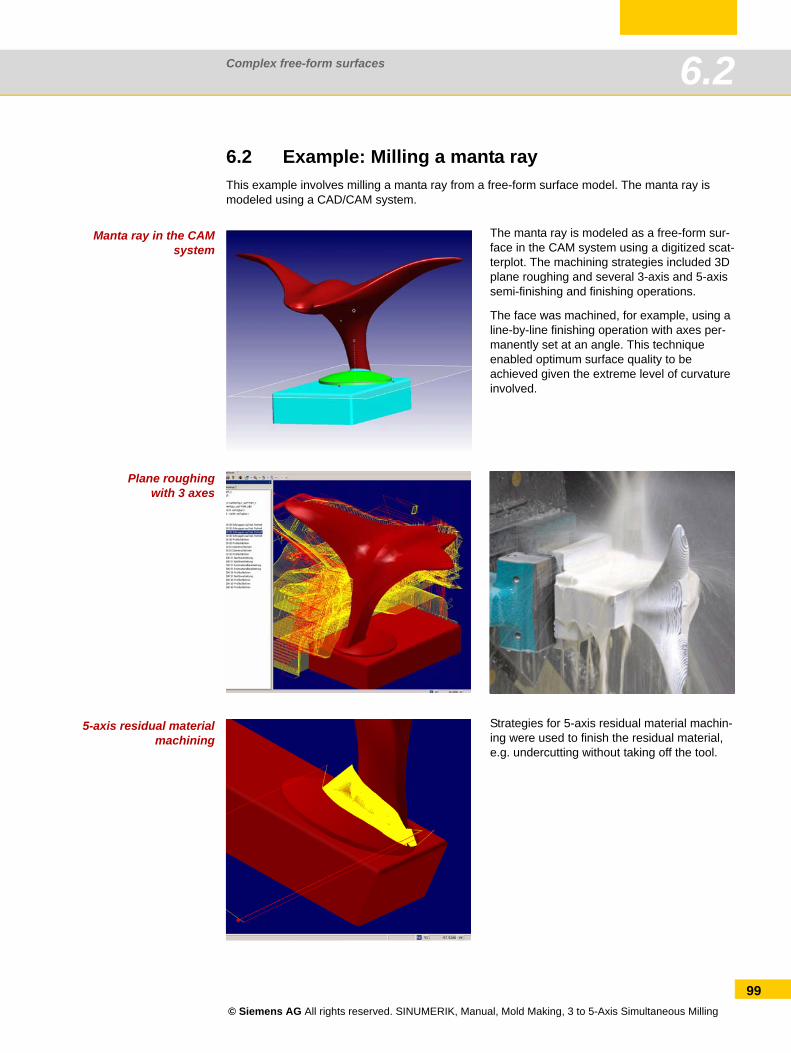
Complex free-form surfaces 6.2
6.2 Example: Milling a manta rayThis example involves milling a manta ray from a free-form surface model. The manta ray is modeled using a CAD/CAM system.
Manta ray in the CAMsystem
Plane roughingwith 3 axes
5-axis residual materialmachining
The manta ray is modeled as a free-form sur-face in the CAM system using a digitized scat-terplot. The machining strategies included 3D plane roughing and several 3-axis and 5-axis semi-finishing and finishing operations.
The face was machined, for example, using a line-by-line finishing operation with axes per-manently set at an angle. This technique enabled optimum surface quality to be achieved given the extreme level of curvature involved.
Strategies for 5-axis residual material machin-ing were used to finish the residual material, e.g. undercutting without taking off the tool.
© Siemens AG All rights reserved. SINUMERIK, Manual, Mold Making, 3 to 5-Axis Simultaneous Milling
99
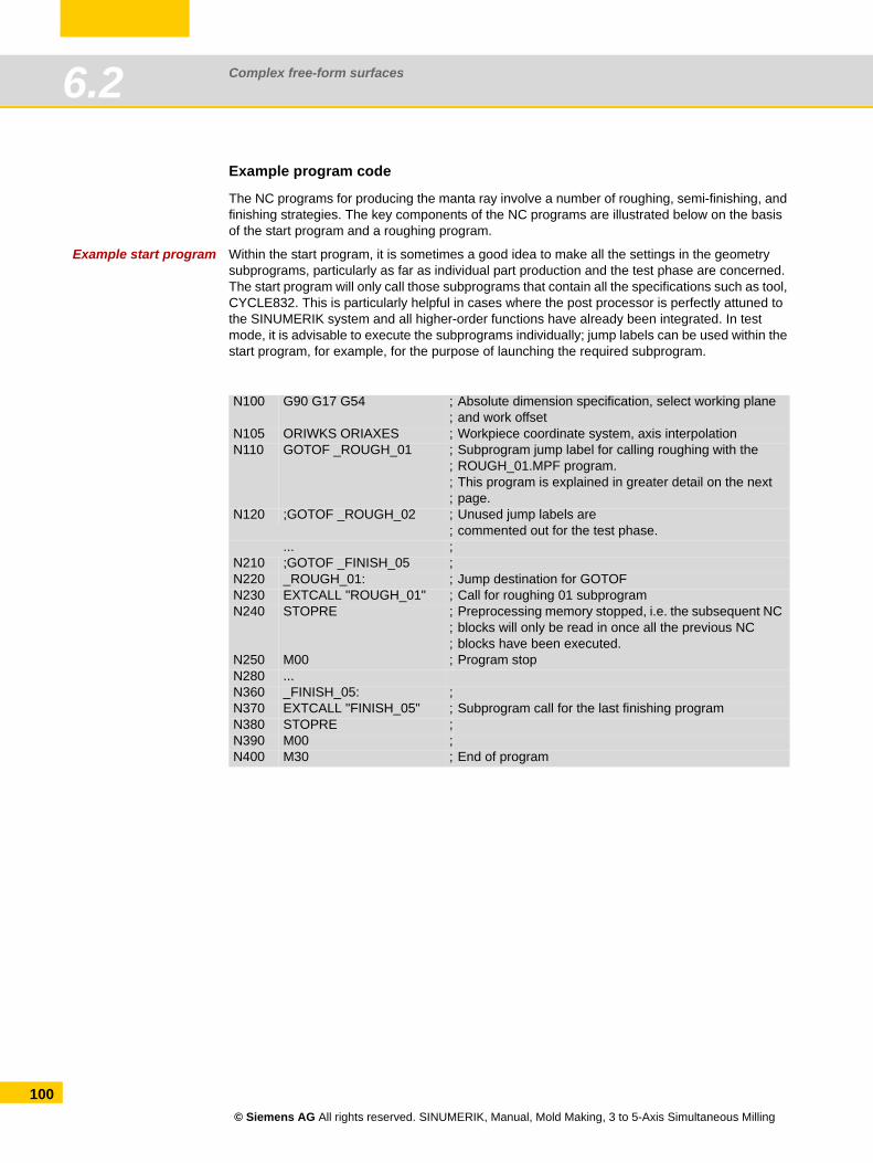
Complex free-form surfaces6.2
100
Example program code
The NC programs for producing the manta ray involve a number of roughing, semi-finishing, and finishing strategies. The key components of the NC programs are illustrated below on the basis of the start program and a roughing program.
Example start program Within the start program, it is sometimes a good idea to make all the settings in the geometry subprograms, particularly as far as individual part production and the test phase are concerned. The start program will only call those subprograms that contain all the specifications such as tool, CYCLE832. This is particularly helpful in cases where the post processor is perfectly attuned to the SINUMERIK system and all higher-order functions have already been integrated. In test mode, it is advisable to execute the subprograms individually; jump labels can be used within the start program, for example, for the purpose of launching the required subprogram.
N100 G90 G17 G54 ;;
Absolute dimension specification, select working plane and work offset
N105 ORIWKS ORIAXES ; Workpiece coordinate system, axis interpolationN110 GOTOF _ROUGH_01 ;
;;;
Subprogram jump label for calling roughing with the ROUGH_01.MPF program.This program is explained in greater detail on the next page.
N120 ;GOTOF _ROUGH_02 ; Unused jump labels are; commented out for the test phase.
... ;N210 ;GOTOF _FINISH_05 ;N220 _ROUGH_01: ; Jump destination for GOTOFN230 EXTCALL "ROUGH_01" ; Call for roughing 01 subprogramN240 STOPRE ;
;;
Preprocessing memory stopped, i.e. the subsequent NC blocks will only be read in once all the previous NC blocks have been executed.
N250 M00 ; Program stopN280 ...N360 _FINISH_05: ;N370 EXTCALL "FINISH_05" ; Subprogram call for the last finishing programN380 STOPRE ;N390 M00 ;N400 M30 ; End of program
© Siemens AG All rights reserved. SINUMERIK, Manual, Mold Making, 3 to 5-Axis Simultaneous Milling
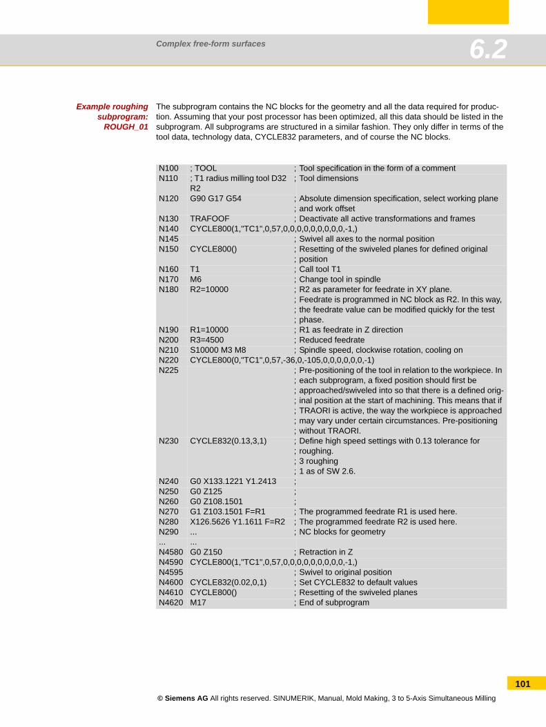
Complex free-form surfaces 6.2
Example roughingsubprogram:
ROUGH_01
The subprogram contains the NC blocks for the geometry and all the data required for produc-tion. Assuming that your post processor has been optimized, all this data should be listed in the subprogram. All subprograms are structured in a similar fashion. They only differ in terms of the tool data, technology data, CYCLE832 parameters, and of course the NC blocks.
N100 ; TOOL ; Tool specification in the form of a commentN110 ; T1 radius milling tool D32
R2; Tool dimensions
N120 G90 G17 G54 ;;
Absolute dimension specification, select working plane and work offset
N130 TRAFOOF ; Deactivate all active transformations and framesN140 CYCLE800(1,"TC1",0,57,0,0,0,0,0,0,0,0,0,-1,)N145 ; Swivel all axes to the normal positionN150 CYCLE800() ;
;Resetting of the swiveled planes for defined original position
N160 T1 ; Call tool T1N170 M6 ; Change tool in spindleN180 R2=10000 ;
;;;
R2 as parameter for feedrate in XY plane.Feedrate is programmed in NC block as R2. In this way, the feedrate value can be modified quickly for the test phase.
N190 R1=10000 ; R1 as feedrate in Z directionN200 R3=4500 ; Reduced feedrateN210 S10000 M3 M8 ; Spindle speed, clockwise rotation, cooling onN220 CYCLE800(0,"TC1",0,57,-36,0,-105,0,0,0,0,0,0,-1)N225 ;
;;;;;;
Pre-positioning of the tool in relation to the workpiece. In each subprogram, a fixed position should first be approached/swiveled into so that there is a defined orig-inal position at the start of machining. This means that if TRAORI is active, the way the workpiece is approached may vary under certain circumstances. Pre-positioning without TRAORI.
N230 CYCLE832(0.13,3,1) ;;;;
Define high speed settings with 0.13 tolerance for roughing. 3 roughing1 as of SW 2.6.
N240 G0 X133.1221 Y1.2413 ;N250 G0 Z125 ;N260 G0 Z108.1501 ;N270 G1 Z103.1501 F=R1 ; The programmed feedrate R1 is used here.N280 X126.5626 Y1.1611 F=R2 ; The programmed feedrate R2 is used here.N290 ... ; NC blocks for geometry... ...N4580 G0 Z150 ; Retraction in ZN4590 CYCLE800(1,"TC1",0,57,0,0,0,0,0,0,0,0,0,-1,)N4595 ; Swivel to original positionN4600 CYCLE832(0.02,0,1) ; Set CYCLE832 to default valuesN4610 CYCLE800() ; Resetting of the swiveled planesN4620 M17 ; End of subprogram
© Siemens AG All rights reserved. SINUMERIK, Manual, Mold Making, 3 to 5-Axis Simultaneous Milling
101

Complex free-form surfaces6.2
102
© Siemens AG All rights reserved. SINUMERIK, Manual, Mold Making, 3 to 5-Axis Simultaneous Milling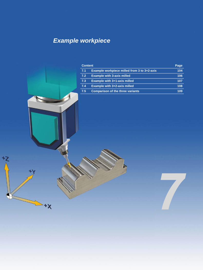
Example workpiece
Content Page7.1 Example workpiece milled from 3 to 3+2-axis 1047.2 Example with 3-axis milled 1067.3 Example with 3+1-axis milled 1077.4 Example with 3+2-axis milled 1087.5 Comparison of the three variants 109
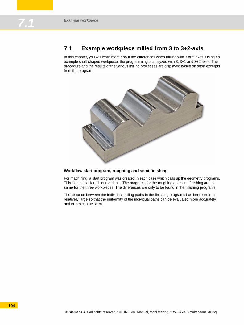
Example workpiece7.1
104
7.1 Example workpiece milled from 3 to 3+2-axisIn this chapter, you will learn more about the differences when milling with 3 or 5 axes. Using an example shaft-shaped workpiece, the programming is analyzed with 3, 3+1 and 3+2 axes. The procedure and the results of the various milling processes are displayed based on short excerpts from the program.
Workflow start program, roughing and semi-finishing
For machining, a start program was created in each case which calls up the geometry programs. This is identical for all four variants. The programs for the roughing and semi-finishing are the same for the three workpieces. The differences are only to be found in the finishing programs.
The distance between the individual milling paths in the finishing programs has been set to be relatively large so that the uniformity of the individual paths can be evaluated more accurately and errors can be seen.
© Siemens AG All rights reserved. SINUMERIK, Manual, Mold Making, 3 to 5-Axis Simultaneous Milling
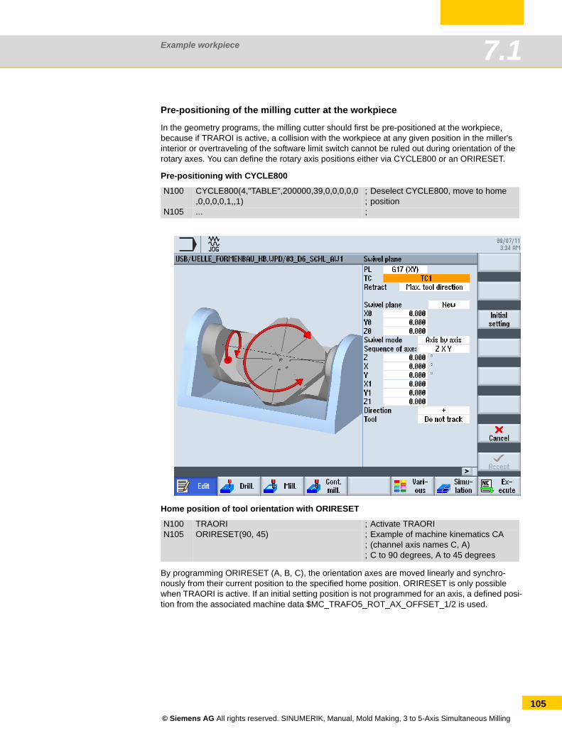
Example workpiece 7.1
Pre-positioning of the milling cutter at the workpiece
In the geometry programs, the milling cutter should first be pre-positioned at the workpiece, because if TRAROI is active, a collision with the workpiece at any given position in the miller's interior or overtraveling of the software limit switch cannot be ruled out during orientation of the rotary axes. You can define the rotary axis positions either via CYCLE800 or an ORIRESET.
Pre-positioning with CYCLE800
Home position of tool orientation with ORIRESET
By programming ORIRESET (A, B, C), the orientation axes are moved linearly and synchro-nously from their current position to the specified home position. ORIRESET is only possible when TRAORI is active. If an initial setting position is not programmed for an axis, a defined posi-tion from the associated machine data $MC_TRAFO5_ROT_AX_OFFSET_1/2 is used.
N100 CYCLE800(4,"TABLE",200000,39,0,0,0,0,0,0,0,0,0,1,,1)
;;
Deselect CYCLE800, move to home position
N105 ... ;
N100 TRAORI ; Activate TRAORIN105 ORIRESET(90, 45) ;
;;
Example of machine kinematics CA (channel axis names C, A)C to 90 degrees, A to 45 degrees
© Siemens AG All rights reserved. SINUMERIK, Manual, Mold Making, 3 to 5-Axis Simultaneous Milling
105
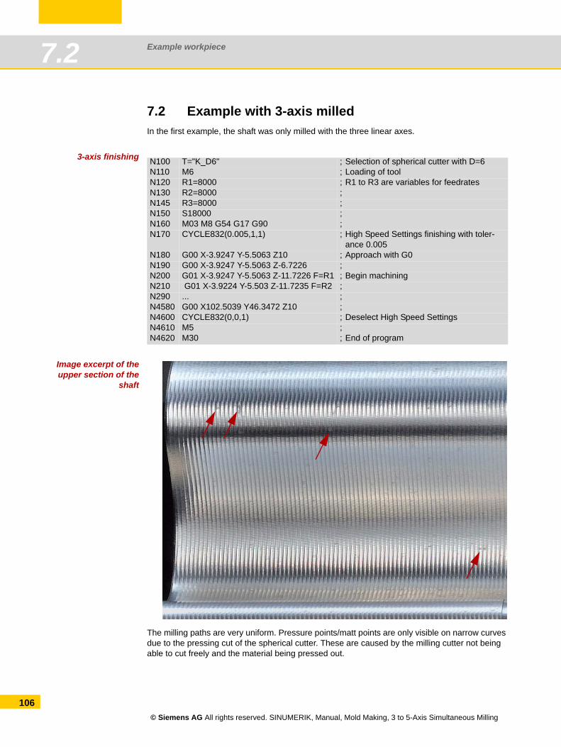
Example workpiece7.2
106
7.2 Example with 3-axis milledIn the first example, the shaft was only milled with the three linear axes.
3-axis finishing
Image excerpt of theupper section of the
shaft
The milling paths are very uniform. Pressure points/matt points are only visible on narrow curves due to the pressing cut of the spherical cutter. These are caused by the milling cutter not being able to cut freely and the material being pressed out.
N100 T="K_D6" ; Selection of spherical cutter with D=6N110 M6 ; Loading of toolN120 R1=8000 ; R1 to R3 are variables for feedratesN130 R2=8000 ;N145 R3=8000 ;N150 S18000 ;N160 M03 M8 G54 G17 G90 ;N170 CYCLE832(0.005,1,1) ; High Speed Settings finishing with toler-
ance 0.005N180 G00 X-3.9247 Y-5.5063 Z10 ; Approach with G0N190 G00 X-3.9247 Y-5.5063 Z-6.7226 ;N200 G01 X-3.9247 Y-5.5063 Z-11.7226 F=R1 ; Begin machiningN210 G01 X-3.9224 Y-5.503 Z-11.7235 F=R2 ;N290 ... ;N4580 G00 X102.5039 Y46.3472 Z10 ;N4600 CYCLE832(0,0,1) ; Deselect High Speed SettingsN4610 M5 ;N4620 M30 ; End of program
© Siemens AG All rights reserved. SINUMERIK, Manual, Mold Making, 3 to 5-Axis Simultaneous Milling
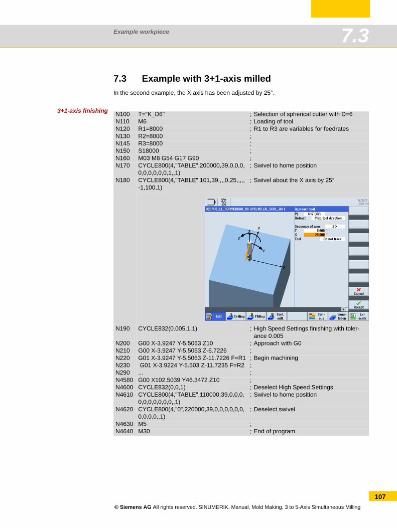
Example workpiece 7.3
7.3 Example with 3+1-axis milledIn the second example, the X axis has been adjusted by 25°.
3+1-axis finishing N100 T="K_D6" ; Selection of spherical cutter with D=6N110 M6 ; Loading of toolN120 R1=8000 ; R1 to R3 are variables for feedratesN130 R2=8000 ;N145 R3=8000 ;N150 S18000 ;N160 M03 M8 G54 G17 G90 ;N170 CYCLE800(4,"TABLE",200000,39,0,0,0,
0,0,0,0,0,0,1,,1); Swivel to home position
N180 CYCLE800(4,"TABLE",101,39,,,,0,25,,,,,-1,100,1)
; Swivel about the X axis by 25°
N190 CYCLE832(0.005,1,1) ; High Speed Settings finishing with toler-ance 0.005
N200 G00 X-3.9247 Y-5.5063 Z10 ; Approach with G0N210 G00 X-3.9247 Y-5.5063 Z-6.7226 ;N220 G01 X-3.9247 Y-5.5063 Z-11.7226 F=R1 ; Begin machiningN230 G01 X-3.9224 Y-5.503 Z-11.7235 F=R2 ;N290 ... ;N4580 G00 X102.5039 Y46.3472 Z10 ;N4600 CYCLE832(0,0,1) ; Deselect High Speed SettingsN4610 CYCLE800(4,"TABLE",110000,39,0,0,0,
0,0,0,0,0,0,0,,1); Swivel to home position
N4620 CYCLE800(4,"0",220000,39,0,0,0,0,0,0,0,0,0,0,,1)
; Deselect swivel
N4630 M5 ;N4640 M30 ; End of program
© Siemens AG All rights reserved. SINUMERIK, Manual, Mold Making, 3 to 5-Axis Simultaneous Milling
107
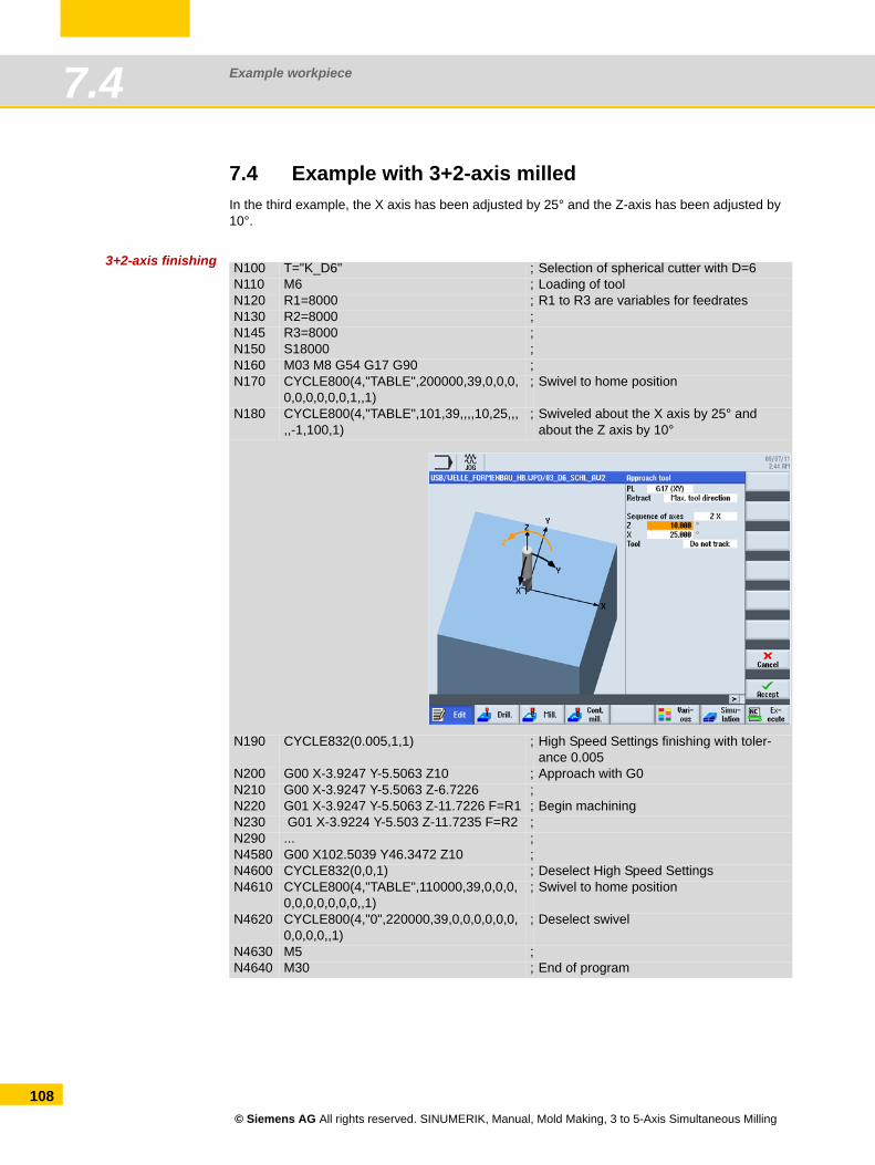
Example workpiece7.4
108
7.4 Example with 3+2-axis milledIn the third example, the X axis has been adjusted by 25° and the Z-axis has been adjusted by 10°.
3+2-axis finishing N100 T="K_D6" ; Selection of spherical cutter with D=6N110 M6 ; Loading of toolN120 R1=8000 ; R1 to R3 are variables for feedratesN130 R2=8000 ;N145 R3=8000 ;N150 S18000 ;N160 M03 M8 G54 G17 G90 ;N170 CYCLE800(4,"TABLE",200000,39,0,0,0,
0,0,0,0,0,0,1,,1); Swivel to home position
N180 CYCLE800(4,"TABLE",101,39,,,,10,25,,,,,-1,100,1)
; Swiveled about the X axis by 25° and about the Z axis by 10°
N190 CYCLE832(0.005,1,1) ; High Speed Settings finishing with toler-ance 0.005
N200 G00 X-3.9247 Y-5.5063 Z10 ; Approach with G0N210 G00 X-3.9247 Y-5.5063 Z-6.7226 ;N220 G01 X-3.9247 Y-5.5063 Z-11.7226 F=R1 ; Begin machiningN230 G01 X-3.9224 Y-5.503 Z-11.7235 F=R2 ;N290 ... ;N4580 G00 X102.5039 Y46.3472 Z10 ;N4600 CYCLE832(0,0,1) ; Deselect High Speed SettingsN4610 CYCLE800(4,"TABLE",110000,39,0,0,0,
0,0,0,0,0,0,0,,1); Swivel to home position
N4620 CYCLE800(4,"0",220000,39,0,0,0,0,0,0,0,0,0,0,,1)
; Deselect swivel
N4630 M5 ;N4640 M30 ; End of program
© Siemens AG All rights reserved. SINUMERIK, Manual, Mold Making, 3 to 5-Axis Simultaneous Milling
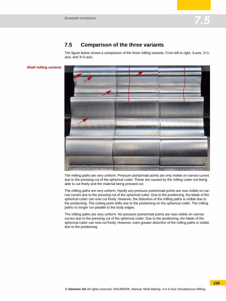
Example workpiece 7.5
7.5 Comparison of the three variantsThe figure below shows a comparison of the three milling variants. From left to right, 3-axis, 3+1-axis, and 3+2-axis.
Shaft milling variants
The milling paths are very uniform. Pressure points/matt points are only visible on narrow curves due to the pressing cut of the spherical cutter. These are caused by the milling cutter not being able to cut freely and the material being pressed out.
The milling paths are very uniform. Hardly any pressure points/matt points are now visible on nar-row curves due to the pressing cut of the spherical cutter. Due to the positioning, the blade of the spherical cutter can now cut freely. However, the distortion of the milling paths is visible due to the positioning. The cutting point drifts due to the positioning on the spherical cutter. The milling paths no longer run parallel to the body edges.
The milling paths are very uniform. No pressure points/matt points are now visible on narrow curves due to the pressing cut of the spherical cutter. Due to the positioning, the blade of the spherical cutter can now cut freely. However, even greater distortion of the milling paths is visible due to the positioning.
© Siemens AG All rights reserved. SINUMERIK, Manual, Mold Making, 3 to 5-Axis Simultaneous Milling
109
Example workpiece7.5
110
© Siemens AG All rights reserved. SINUMERIK, Manual, Mold Making, 3 to 5-Axis Simultaneous Milling
Reference section
Content Page8.1 Overview of higher-order functions 1128.2 Further information/documentation 1228.3 Index 124
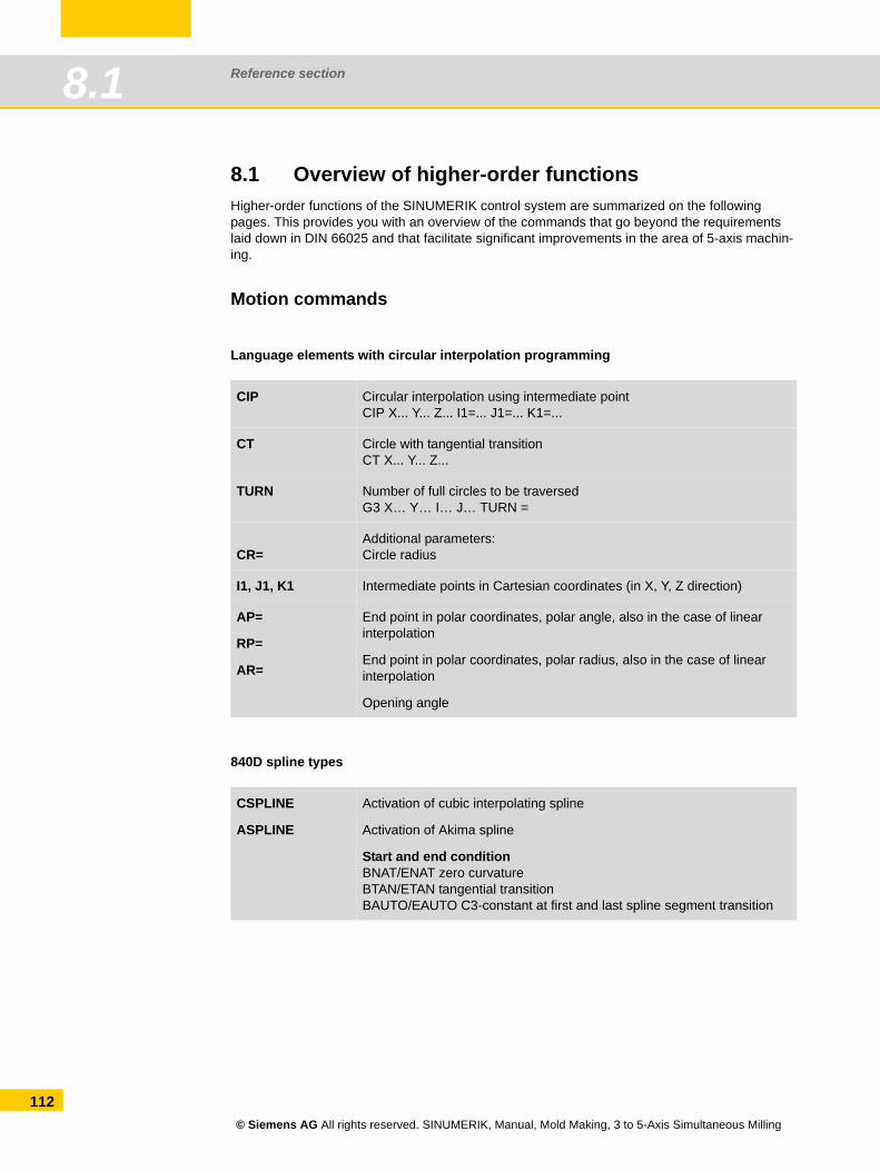
Reference section8.1
112
8.1 Overview of higher-order functions Higher-order functions of the SINUMERIK control system are summarized on the following pages. This provides you with an overview of the commands that go beyond the requirements laid down in DIN 66025 and that facilitate significant improvements in the area of 5-axis machin-ing.
Motion commands
Language elements with circular interpolation programming
840D spline types
CIP Circular interpolation using intermediate pointCIP X... Y... Z... I1=... J1=... K1=...
CT Circle with tangential transitionCT X... Y... Z...
TURN Number of full circles to be traversedG3 X… Y… I… J… TURN =
CR=Additional parameters:Circle radius
I1, J1, K1 Intermediate points in Cartesian coordinates (in X, Y, Z direction)
AP=
RP=
AR=
End point in polar coordinates, polar angle, also in the case of linear interpolation
End point in polar coordinates, polar radius, also in the case of linear interpolation
Opening angle
CSPLINE
ASPLINE
Activation of cubic interpolating spline
Activation of Akima spline
Start and end conditionBNAT/ENAT zero curvatureBTAN/ETAN tangential transitionBAUTO/EAUTO C3-constant at first and last spline segment transition
© Siemens AG All rights reserved. SINUMERIK, Manual, Mold Making, 3 to 5-Axis Simultaneous Milling
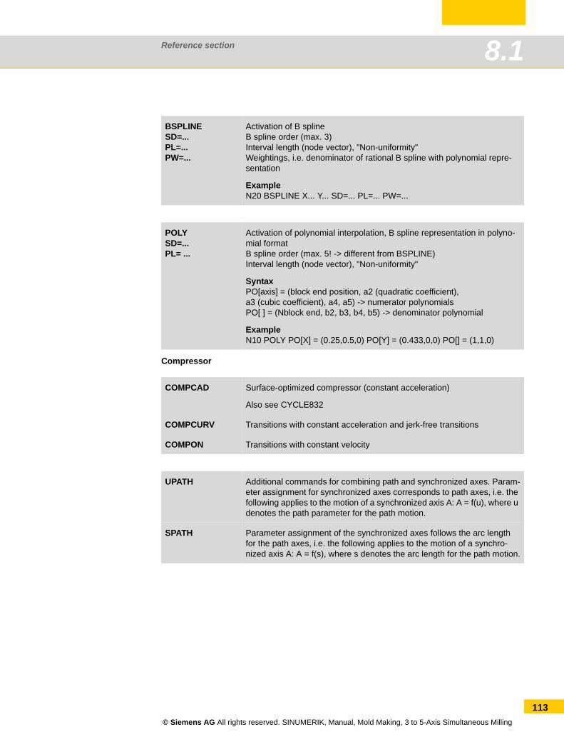
Reference section 8.1
Compressor
BSPLINESD=... PL=... PW=...
Activation of B splineB spline order (max. 3)Interval length (node vector), "Non-uniformity"Weightings, i.e. denominator of rational B spline with polynomial repre-sentation
ExampleN20 BSPLINE X... Y... SD=... PL=... PW=...
POLYSD=...PL= ...
Activation of polynomial interpolation, B spline representation in polyno-mial formatB spline order (max. 5! -> different from BSPLINE)Interval length (node vector), "Non-uniformity"
SyntaxPO[axis] = (block end position, a2 (quadratic coefficient),a3 (cubic coefficient), a4, a5) -> numerator polynomialsPO[ ] = (Nblock end, b2, b3, b4, b5) -> denominator polynomial
ExampleN10 POLY PO[X] = (0.25,0.5,0) PO[Y] = (0.433,0,0) PO[] = (1,1,0)
COMPCAD Surface-optimized compressor (constant acceleration)
Also see CYCLE832
COMPCURV Transitions with constant acceleration and jerk-free transitions
COMPON Transitions with constant velocity
UPATH Additional commands for combining path and synchronized axes. Param-eter assignment for synchronized axes corresponds to path axes, i.e. the following applies to the motion of a synchronized axis A: A = f(u), where u denotes the path parameter for the path motion.
SPATH Parameter assignment of the synchronized axes follows the arc length for the path axes, i.e. the following applies to the motion of a synchro-nized axis A: A = f(s), where s denotes the arc length for the path motion.
© Siemens AG All rights reserved. SINUMERIK, Manual, Mold Making, 3 to 5-Axis Simultaneous Milling
113
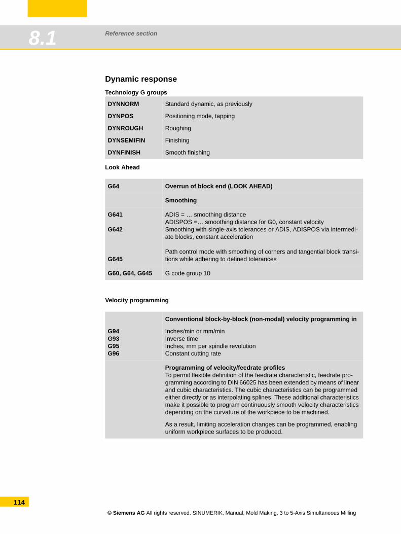
Reference section8.1
114
Dynamic responseTechnology G groups
Look Ahead
Velocity programming
DYNNORM
DYNPOS
DYNROUGH
DYNSEMIFIN
DYNFINISH
Standard dynamic, as previously
Positioning mode, tapping
Roughing
Finishing
Smooth finishing
G64 Overrun of block end (LOOK AHEAD)
Smoothing
G641
G642
G645
ADIS = … smoothing distanceADISPOS =… smoothing distance for G0, constant velocitySmoothing with single-axis tolerances or ADIS, ADISPOS via intermedi-ate blocks, constant acceleration
Path control mode with smoothing of corners and tangential block transi-tions while adhering to defined tolerances
G60, G64, G645 G code group 10
G94 G93 G95 G96
Conventional block-by-block (non-modal) velocity programming in
Inches/min or mm/minInverse timeInches, mm per spindle revolutionConstant cutting rate
Programming of velocity/feedrate profilesTo permit flexible definition of the feedrate characteristic, feedrate pro-gramming according to DIN 66025 has been extended by means of linear and cubic characteristics. The cubic characteristics can be programmed either directly or as interpolating splines. These additional characteristics make it possible to program continuously smooth velocity characteristics depending on the curvature of the workpiece to be machined.
As a result, limiting acceleration changes can be programmed, enabling uniform workpiece surfaces to be produced.
© Siemens AG All rights reserved. SINUMERIK, Manual, Mold Making, 3 to 5-Axis Simultaneous Milling
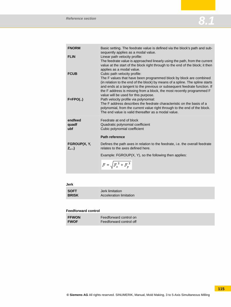
Reference section 8.1
Jerk
Feedforward control
FNORM
FLIN
FCUB
F=FPO(..)
Basic setting. The feedrate value is defined via the block's path and sub-sequently applies as a modal value.Linear path velocity profile:The feedrate value is approached linearly using the path, from the current value at the start of the block right through to the end of the block; it then applies as a modal value.Cubic path velocity profile:The F values that have been programmed block by block are combined (in relation to the end of the block) by means of a spline. The spline starts and ends at a tangent to the previous or subsequent feedrate function. If the F address is missing from a block, the most recently programmed F value will be used for this purpose.Path velocity profile via polynomial:The F address describes the feedrate characteristic on the basis of a polynomial, from the current value right through to the end of the block. The end value is valid thereafter as a modal value.
endfeedquadfubf
Feedrate at end of blockQuadratic polynomial coefficientCubic polynomial coefficient
FGROUP(X, Y, Z,...)
Path reference
Defines the path axes in relation to the feedrate, i.e. the overall feedrate relates to the axes defined here.
Example: FGROUP(X, Y), so the following then applies:
SOFTBRISK
Jerk limitationAcceleration limitation
FFWONFWOF
Feedforward control onFeedforward control off
© Siemens AG All rights reserved. SINUMERIK, Manual, Mold Making, 3 to 5-Axis Simultaneous Milling
115
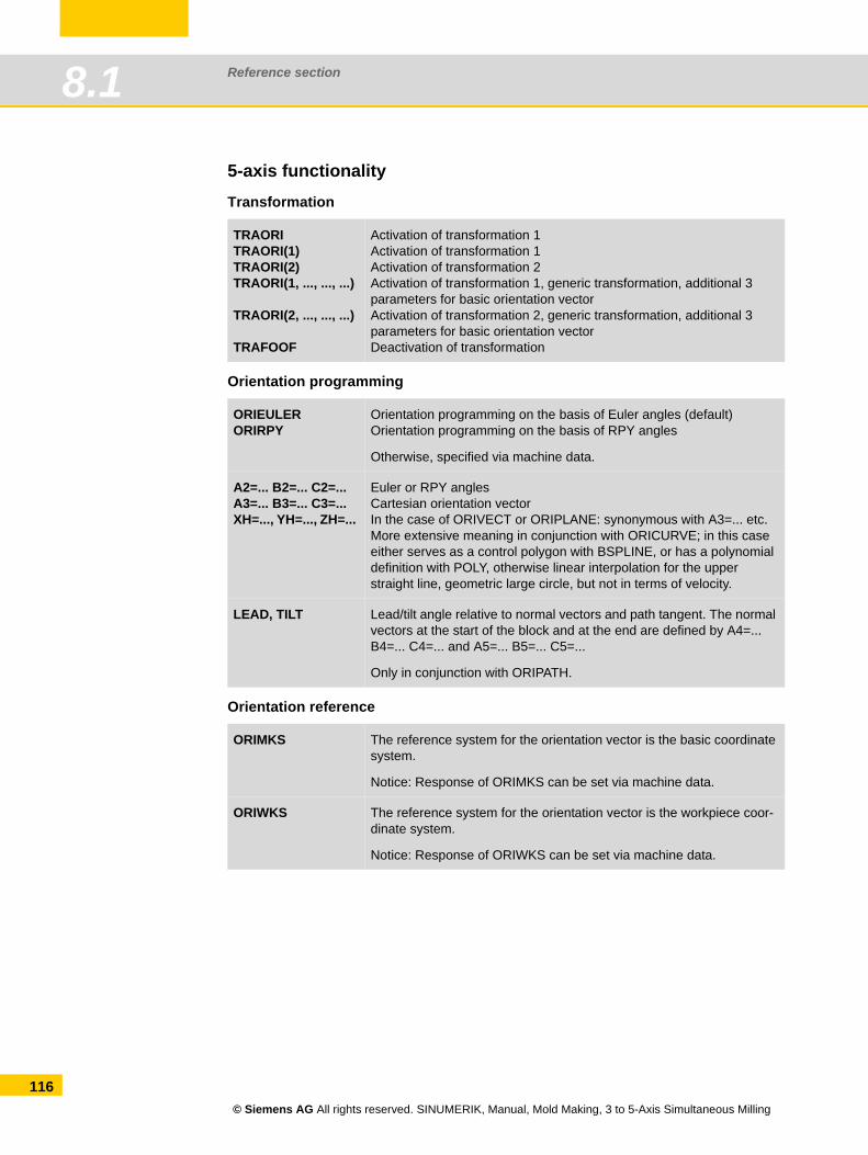
Reference section8.1
116
5-axis functionalityTransformation
Orientation programming
Orientation reference
TRAORITRAORI(1) TRAORI(2) TRAORI(1, ..., ..., ...)
TRAORI(2, ..., ..., ...)
TRAFOOF
Activation of transformation 1Activation of transformation 1Activation of transformation 2Activation of transformation 1, generic transformation, additional 3 parameters for basic orientation vectorActivation of transformation 2, generic transformation, additional 3 parameters for basic orientation vectorDeactivation of transformation
ORIEULERORIRPY
Orientation programming on the basis of Euler angles (default)Orientation programming on the basis of RPY angles
Otherwise, specified via machine data.
A2=... B2=... C2=...A3=... B3=... C3=...XH=..., YH=..., ZH=...
Euler or RPY anglesCartesian orientation vectorIn the case of ORIVECT or ORIPLANE: synonymous with A3=... etc. More extensive meaning in conjunction with ORICURVE; in this case either serves as a control polygon with BSPLINE, or has a polynomial definition with POLY, otherwise linear interpolation for the upper straight line, geometric large circle, but not in terms of velocity.
LEAD, TILT Lead/tilt angle relative to normal vectors and path tangent. The normal vectors at the start of the block and at the end are defined by A4=... B4=... C4=... and A5=... B5=... C5=...
Only in conjunction with ORIPATH.
ORIMKS The reference system for the orientation vector is the basic coordinate system.
Notice: Response of ORIMKS can be set via machine data.
ORIWKS The reference system for the orientation vector is the workpiece coor-dinate system.
Notice: Response of ORIWKS can be set via machine data.
© Siemens AG All rights reserved. SINUMERIK, Manual, Mold Making, 3 to 5-Axis Simultaneous Milling
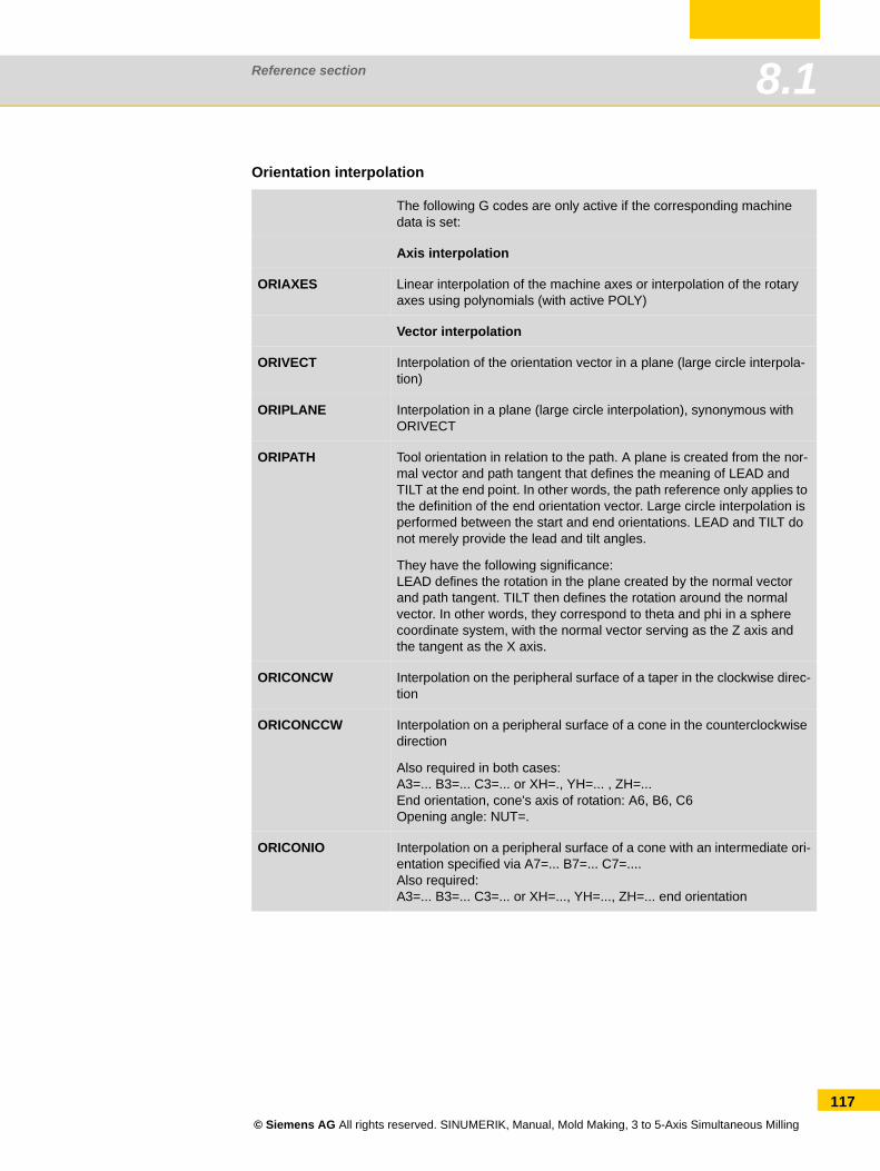
Reference section 8.1
Orientation interpolation
The following G codes are only active if the corresponding machine data is set:
Axis interpolation
ORIAXES Linear interpolation of the machine axes or interpolation of the rotary axes using polynomials (with active POLY)
Vector interpolation
ORIVECT Interpolation of the orientation vector in a plane (large circle interpola-tion)
ORIPLANE Interpolation in a plane (large circle interpolation), synonymous with ORIVECT
ORIPATH Tool orientation in relation to the path. A plane is created from the nor-mal vector and path tangent that defines the meaning of LEAD and TILT at the end point. In other words, the path reference only applies to the definition of the end orientation vector. Large circle interpolation is performed between the start and end orientations. LEAD and TILT do not merely provide the lead and tilt angles.
They have the following significance:LEAD defines the rotation in the plane created by the normal vector and path tangent. TILT then defines the rotation around the normal vector. In other words, they correspond to theta and phi in a sphere coordinate system, with the normal vector serving as the Z axis and the tangent as the X axis.
ORICONCW Interpolation on the peripheral surface of a taper in the clockwise direc-tion
ORICONCCW Interpolation on a peripheral surface of a cone in the counterclockwise direction
Also required in both cases:A3=... B3=... C3=... or XH=., YH=... , ZH=... End orientation, cone's axis of rotation: A6, B6, C6Opening angle: NUT=.
ORICONIO Interpolation on a peripheral surface of a cone with an intermediate ori-entation specified via A7=... B7=... C7=....Also required:A3=... B3=... C3=... or XH=..., YH=..., ZH=... end orientation
© Siemens AG All rights reserved. SINUMERIK, Manual, Mold Making, 3 to 5-Axis Simultaneous Milling
117
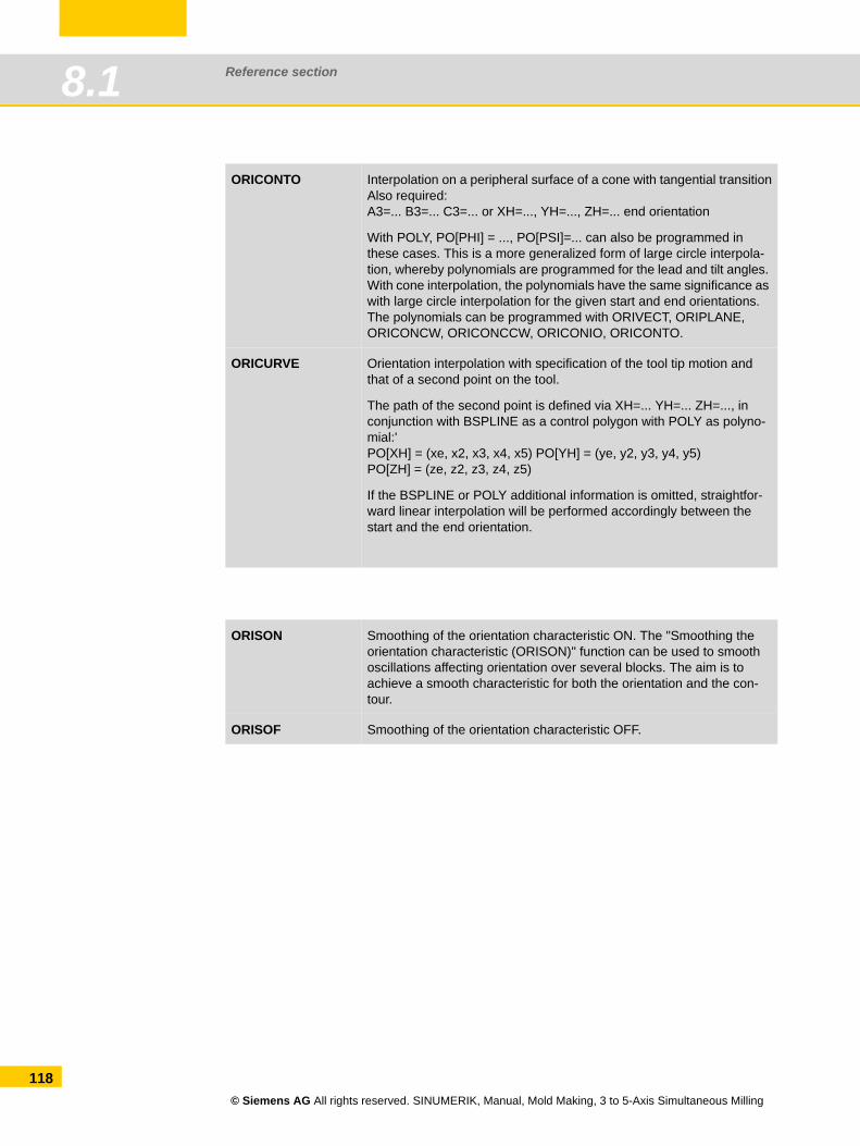
Reference section8.1
118
ORICONTO Interpolation on a peripheral surface of a cone with tangential transitionAlso required:A3=... B3=... C3=... or XH=..., YH=..., ZH=... end orientation
With POLY, PO[PHI] = ..., PO[PSI]=... can also be programmed in these cases. This is a more generalized form of large circle interpola-tion, whereby polynomials are programmed for the lead and tilt angles. With cone interpolation, the polynomials have the same significance as with large circle interpolation for the given start and end orientations. The polynomials can be programmed with ORIVECT, ORIPLANE, ORICONCW, ORICONCCW, ORICONIO, ORICONTO.
ORICURVE Orientation interpolation with specification of the tool tip motion and that of a second point on the tool.
The path of the second point is defined via XH=... YH=... ZH=..., in conjunction with BSPLINE as a control polygon with POLY as polyno-mial:'PO[XH] = (xe, x2, x3, x4, x5) PO[YH] = (ye, y2, y3, y4, y5)PO[ZH] = (ze, z2, z3, z4, z5)
If the BSPLINE or POLY additional information is omitted, straightfor-ward linear interpolation will be performed accordingly between the start and the end orientation.
ORISON Smoothing of the orientation characteristic ON. The "Smoothing the orientation characteristic (ORISON)" function can be used to smooth oscillations affecting orientation over several blocks. The aim is to achieve a smooth characteristic for both the orientation and the con-tour.
ORISOF Smoothing of the orientation characteristic OFF.
© Siemens AG All rights reserved. SINUMERIK, Manual, Mold Making, 3 to 5-Axis Simultaneous Milling
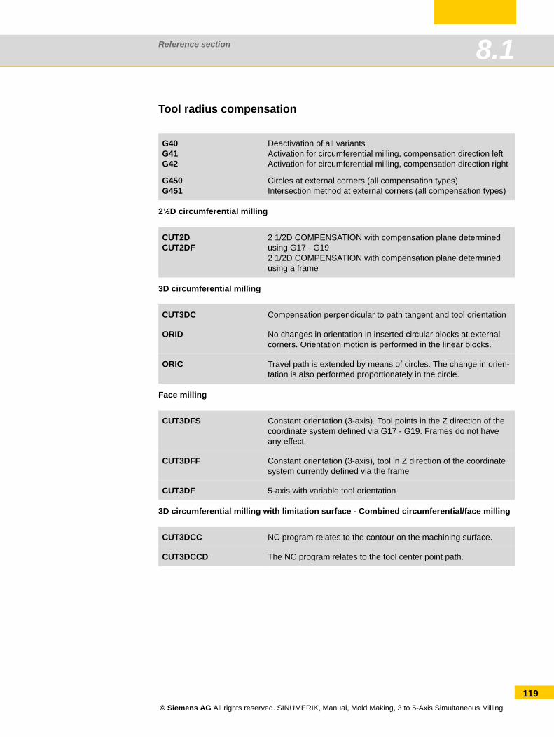
Reference section 8.1
Tool radius compensation
2½D circumferential milling
3D circumferential milling
Face milling
3D circumferential milling with limitation surface - Combined circumferential/face milling
G40G41G42
G450G451
Deactivation of all variantsActivation for circumferential milling, compensation direction left Activation for circumferential milling, compensation direction right
Circles at external corners (all compensation types)Intersection method at external corners (all compensation types)
CUT2D CUT2DF
2 1/2D COMPENSATION with compensation plane determined using G17 - G192 1/2D COMPENSATION with compensation plane determined using a frame
CUT3DC Compensation perpendicular to path tangent and tool orientation
ORID No changes in orientation in inserted circular blocks at external corners. Orientation motion is performed in the linear blocks.
ORIC Travel path is extended by means of circles. The change in orien-tation is also performed proportionately in the circle.
CUT3DFS Constant orientation (3-axis). Tool points in the Z direction of the coordinate system defined via G17 - G19. Frames do not have any effect.
CUT3DFF Constant orientation (3-axis), tool in Z direction of the coordinate system currently defined via the frame
CUT3DF 5-axis with variable tool orientation
CUT3DCC NC program relates to the contour on the machining surface.
CUT3DCCD The NC program relates to the tool center point path.
© Siemens AG All rights reserved. SINUMERIK, Manual, Mold Making, 3 to 5-Axis Simultaneous Milling
119
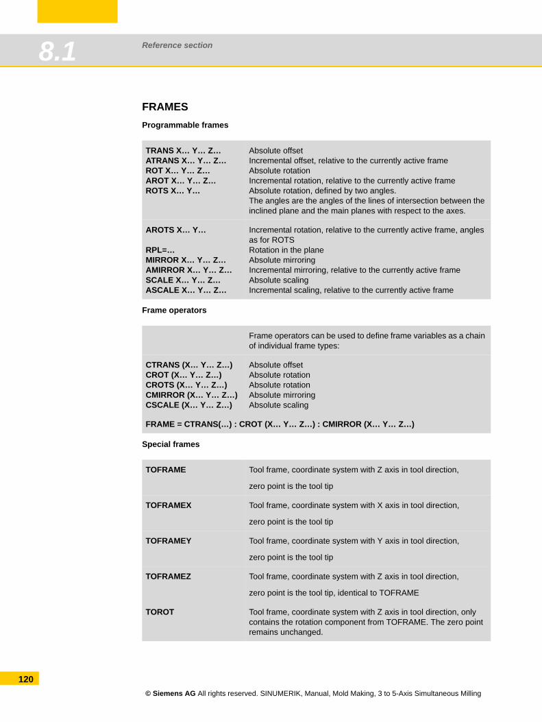
Reference section8.1
120
FRAMESProgrammable frames
Frame operators
Special frames
TRANS X… Y… Z… ATRANS X… Y… Z… ROT X… Y… Z… AROT X… Y… Z… ROTS X… Y…
Absolute offsetIncremental offset, relative to the currently active frameAbsolute rotationIncremental rotation, relative to the currently active frameAbsolute rotation, defined by two angles. The angles are the angles of the lines of intersection between the inclined plane and the main planes with respect to the axes.
AROTS X… Y…
RPL=… MIRROR X… Y… Z… AMIRROR X… Y… Z… SCALE X… Y… Z… ASCALE X… Y… Z…
Incremental rotation, relative to the currently active frame, angles as for ROTSRotation in the planeAbsolute mirroringIncremental mirroring, relative to the currently active frameAbsolute scalingIncremental scaling, relative to the currently active frame
Frame operators can be used to define frame variables as a chain of individual frame types:
CTRANS (X… Y… Z…) CROT (X… Y… Z…) CROTS (X… Y… Z…) CMIRROR (X… Y… Z…) CSCALE (X… Y… Z…)
Absolute offsetAbsolute rotationAbsolute rotationAbsolute mirroringAbsolute scaling
FRAME = CTRANS(…) : CROT (X… Y… Z…) : CMIRROR (X… Y… Z…)
TOFRAME Tool frame, coordinate system with Z axis in tool direction,
zero point is the tool tip
TOFRAMEX Tool frame, coordinate system with X axis in tool direction,
zero point is the tool tip
TOFRAMEY Tool frame, coordinate system with Y axis in tool direction,
zero point is the tool tip
TOFRAMEZ Tool frame, coordinate system with Z axis in tool direction,
zero point is the tool tip, identical to TOFRAME
TOROT Tool frame, coordinate system with Z axis in tool direction, only contains the rotation component from TOFRAME. The zero point remains unchanged.
© Siemens AG All rights reserved. SINUMERIK, Manual, Mold Making, 3 to 5-Axis Simultaneous Milling
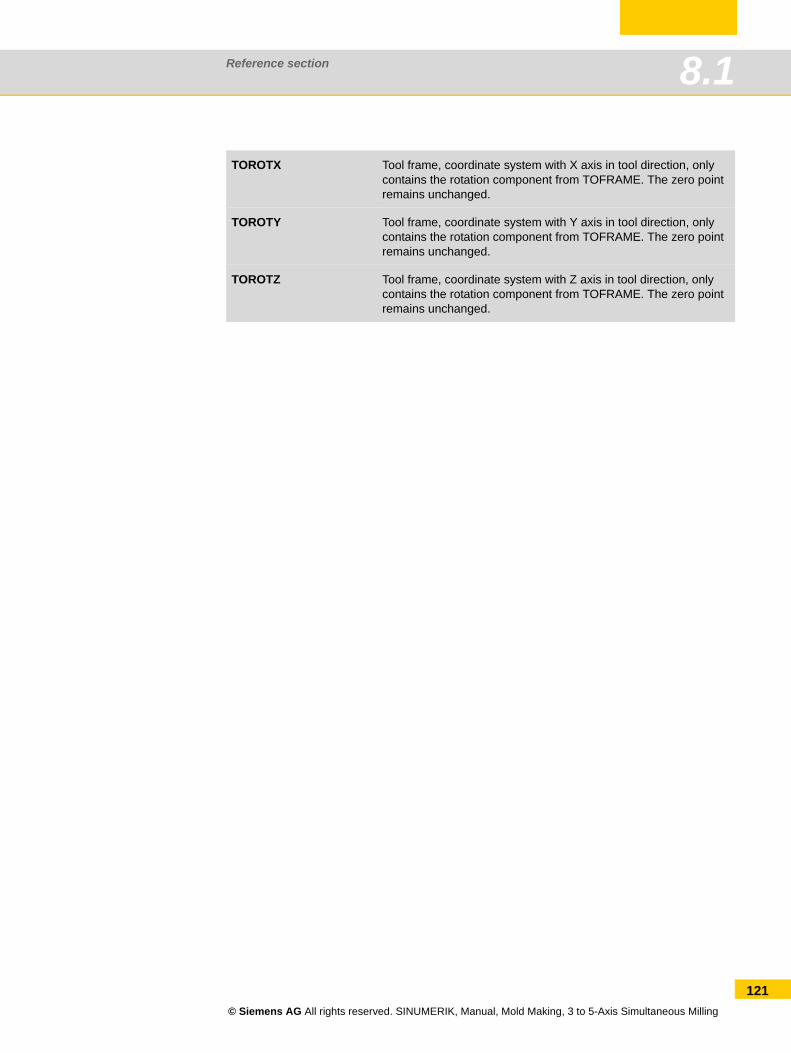
Reference section 8.1
TOROTX Tool frame, coordinate system with X axis in tool direction, only contains the rotation component from TOFRAME. The zero point remains unchanged.
TOROTY Tool frame, coordinate system with Y axis in tool direction, only contains the rotation component from TOFRAME. The zero point remains unchanged.
TOROTZ Tool frame, coordinate system with Z axis in tool direction, only contains the rotation component from TOFRAME. The zero point remains unchanged.
© Siemens AG All rights reserved. SINUMERIK, Manual, Mold Making, 3 to 5-Axis Simultaneous Milling
121
Reference section8.2
122
8.2 Further information/documentationInformation about the SINUMERIK system can be found in a number of sources. User and man-ufacturer documentation is supplemented by user forums and information on the Internet. An overview of this additional information is provided below.
Doconweb
Internet site that enables you to download the SINUMERIK documentation in its entirety. You can search for specific terms online, look things up in the index or download the required manual in PDF format.
www.siemens.com/automation/doconweb
CNC4you - User portal
This portal provides up-to-date information about SINU-MERIK controls and real-life examples.
www.siemens.com/cnc4you
SINUMERIK - User forum
The SINUMERIK user forum is a platform that allows you to discuss technical issues with other SINUMERIK users. The forum is moderated by experienced Siemens technicians.
www.siemens.cnc-arena.com
© Siemens AG All rights reserved. SINUMERIK, Manual, Mold Making, 3 to 5-Axis Simultaneous Milling
Reference section 8.2
© Siemens AG All rights reserved. SINUMERIK, Manual, Mold Making, 3 to 5-Axis Simultaneous Milling
123
Reference section 8.3Reference section
8.3 IndexNumerics
3 to 3+2-axis 1045-axis transformation 51
A
Accuracy 15, 20, 66Advanced Surface 69Align plane 28, 33
Example 29Animated elements 10ATOL 75AUTO mode 33Automatic mode 33, 34
Determining the tool radius 36Measuring the workpiece 34
B
Basic frame 44BRISK 74
C
CAD - CAM - CNC 8Calculate kinematics 38Calibrate probe 28CAM system 19COMCAD
Compressor function 16COMPCAD 71COMPOF 71Compressor 16, 71, 113Compressor function 16Continuous-path mode 72Coordinate systems 44CTOL 68, 75CUST_832 66CYCLE800 45CYCLE832 22, 66
Parameter 67CYCLE996 37CYCLE997
Example 34
D
Determining the tool length 35, 40Direction vector 13Direction vector programming 13Driving gear and turbine components 92Dynamic response 114DYNFINISH 78DYNORM 78DYNPOS 78
DYNROUGH 78DYNSEMIFIN 78
E
Example workpiece 104Explanation of terms
Frames 43Swiveling 43TRAORI 43
EXTCALL 22, 24External storage media 24
F
Feedforward control 74, 115FFWOF 74FFWON 74FIFOCTRL 77Fork 14Frame, frames 120
Frame operators 120Programmable frames 120
Free-form machining 15Free-form surfaces 98
Example 99
G
G code group 59 70G645 72Gauging tools 30
H
High Speed Settings 66
J
Jerk 115Jerk limitation 74JOG 31
Measure tool 31JOG mode 28
K
Kinematics 14Kinematics measuring cycle 37
L
Linear axes 12Look Ahead 114Look ahead 72
M
Machine kinematics 45
© Siemens AG All rights reserved. SINUMERIK, Manual, Mold Making, 3 to 5-Axis Simultaneous Milling
124
Reference section8.3
125
MCS 25Measure corner 28Measure edge 28, 33Measure pocket 34Measure pocket/hole 28Measure spigot 33Measure spigot/hole 28Measure tool 35Measure tool in AUTOMATIC 35Measure tool in JOG 30Measure workpiece in AUTOMATIC 33Measuring cycles 27, 28, 35
Selecting 28Measuring cycles in AUTOMATIC 33Measuring cycles in JOG 28Measuring in JOG and AUTOMATIC 27Mold making view 40Motion commands 112
N
Nutated axis 10, 14
O
OIRMKS 60ORIAXES 61ORICONxx 62Orientation interpolation 59ORIPATH 64ORISON 22, 76ORIVECT/ORIPLANE 61ORIWKS 60OTOL 68, 75
P
Pre-positioning with CYCLE800 105Probe 28, 31, 34Process chain 8, 18
CAD - CAM - CNC 11Process measuring 33Program manager 23Program structure 21Programmable smoothing
Spline interpolation 16
R
Right-angled corner 29Rotary axes 12, 14Rotary axis positions 13Rotary axis programming 13
S
Simulation 39SINUMERIK MDynamics 9SINUMERIK Operate 10
Smoothing of orientation characteristic 76SOFT 74SPATH 75Spline 16Spline compressor 71Structural parts
Example 87Functions 86
Surface quality 8, 15, 66Swivel head 45Swivel table 45Swiveling
Cycle800 45
T
Technology G groups 78, 114Tolerance 20Tolerance_tol. 67Tool
Measuring in JOG 31Tool geometries 30Tool list 26Tool management 26Tool orientation 54
Direction vector 54LEAD/TILT 58ORIEULER/ORIRPY 56Rotary axis positions 55Surface normal vector 57
Tool orientation and kinematics 51Tool radius compensation 119Tool reference point 30Tool table 30Tool type
Milling tool types 31Tool wear list 26TRAORI 51
Function 52Programming 53
U
UPATH 75
V
VCS 82Velocity 15, 66Velocity programming 114VNCK - Virtual machine 83Volumetric compensation system 82
W
WCS 25Work offsets 25Workpiece
© Siemens AG All rights reserved. SINUMERIK, Manual, Mold Making, 3 to 5-Axis Simultaneous Milling
Reference section 8.3
Setup 28Workpiece visualization 39
© Siemens AG All rights reserved. SINUMERIK, Manual, Mold Making, 3 to 5-Axis Simultaneous Milling
126

www.siemens.com/sinumerik
Subject to change without prior notice6FC5095-0AB10-0BP2© Siemens AG 2011
Siemens AGIndustry SectorDrive TechnologiesMotion ControlPostfach 318091050 ErlangenDEUTSCHLAND
Direct online ordering is possible in our mall:www.siemens.com/automation/mall
For detailed technical documentation refer to ourService&Support Portal:www.siemens.com/automation/support
More details on SINUMERIK are available under:www.siemens.com/sinumerik
Further information
For contac persons near you refer to:www.siemens.com/automation/partner