Module 2 ENERGY EFFICIENCY IN THERMAL SYSTEMS 2...Module -2: Energy Efficiency in Thermal Systems 2...
229
c c ENERGY EFFICIENCY IN THERMAL SYSTEMS Module 2 Sustainable and Renewable Energy Development Authority Power Division First Edition’2019
Transcript of Module 2 ENERGY EFFICIENCY IN THERMAL SYSTEMS 2...Module -2: Energy Efficiency in Thermal Systems 2...

c
c
ENERGY EFFICIENCY
IN
THERMAL SYSTEMS
Module 2
Sustainable and Renewable Energy Development Authority
Power Division
First Edition’2019

Preamble
In order to ensure energy efficiency and conservation and to determine the future course
of action, Sustainable and Renewable Energy Development Authority (SREDA) has
developed the Energy Efficiency & Conservation Master Plan up to 2030 in 2016.
According to this plan, the target of energy saving has been set 15% & 20% per GDP by
2020 & 2030 respectively which will be achieved by the use of energy efficient machinery
and equipment as well as by improving energy management system in the demand side .
In order to achieve the above mentioned target & to ensure the energy efficiency and
conservation in industrial & commercial sector, SREDA has formulated the Energy Audit
Regulation’2018. Based on this regulation, SREDA will conduct the Energy Auditor
Certification Examination to create energy auditors and energy managers in Bangladesh.
SREDA has prepared the following modules as reading material for four paper
examinations in cooperation with various National and Foreign partner organizations.
Module No Examination
Paper
Subject
Module 01 Paper 01 Fundamentals of Energy Management and Energy
Audit
Module 02 Paper 02 Energy Efficiency in Thermal Systems
Module 03 Paper 03 Energy Efficiency in Electrical Systems
Module 04 Paper 04 Energy Performance Assessment for Equipment
and Utility Systems
This module 02 on Energy Efficiency in Thermal Systems is the reading material for the
preparation of Paper 02 Examination for prospective candidates.
We hope that these modules will also act as valuable resource for practicing engineers in
comprehending and implementing energy efficiency measures in the facilities.
It is the first iteration of these modules. It will be a living document which can be reviewed
and revised time to time according to the evolution of the technology and industry. Any
suggestion and comments (please email to [email protected] ) on the contents of those
modules will be highly appreciated.


Table of Contents Chapter 1: Fuels and Combustion ............................................................................................. 1
1.1 Introduction to Fuels ......................................................................................................... 1 1.2 Properties of Liquid Fuels ................................................................................................ 1 1.3 Properties of Coal .............................................................................................................. 6 1.4 Properties of Gaseous Fuels .......................................................................................... 12 1.5 Properties of Agro Residues .......................................................................................... 13 1.6 Combustion ...................................................................................................................... 14 1.7 Combustion of Oil............................................................................................................ 16 1.8 Combustion of Coal ........................................................................................................ 21 1.9 Combustion of Gas ......................................................................................................... 23 1.10 Combustion of Biomass ............................................................................................... 24 1.11 Draft ................................................................................................................................. 26 1.12 Combustion Controls .................................................................................................... 27
Chapter 2: Boiler ........................................................................................................................ 30 2.1 Introduction ...................................................................................................................... 30 2.2 Boiler Systems ................................................................................................................. 31 2.3 Boiler Types and Classifications ................................................................................... 32 2.4 Performance Evaluation of Boilers................................................................................ 38 2.5 Boiler Blow down............................................................................................................. 44 2.6 Boiler Water Treatment ................................................................................................... 46 2.7 Energy Conservation Opportunities.............................................................................. 52 2.8 Case Study ....................................................................................................................... 58
Chapter 3: Steam System ........................................................................................................ 63 3.1 Introduction ...................................................................................................................... 63 3.2 Properties of Steam ......................................................................................................... 63 3.3 Steam Distribution System ............................................................................................. 66 3.4 Efficient Steam Utilization .............................................................................................. 73 3.5 Proper Selection, Operation and Maintenance of Steam Traps ................................. 78 3.6 Performance Assessment Methods for Steam Traps.................................................. 88 3.7 Energy Saving Opportunities ......................................................................................... 90
Chapter 4: Industrial Furnaces ............................................................................................... 104 4.1 Types and Classification of Different Furnaces ......................................................... 104 4.2 Performance Evaluation of a Fuel Fired Furnace ....................................................... 119 4.3 General Fuel Economy Measures in Furnaces .......................................................... 128 Case Study 4.1 ..................................................................................................................... 142
Chapter 5: Insulation and Refractories ................................................................................. 145 5.1 Insulation ........................................................................................................................ 145
5.1.1 Purpose of Insulation ............................................................................................. 145 5.1.2 Types and Application ........................................................................................... 145 5.1.3 Thermal Resistance (R) ......................................................................................... 147 5.1.4 Economic Thickness of Insulation (ETI) .............................................................. 148 5.1.5 Heat Savings and Application Criteria ................................................................. 149 5.1.6 Cold Insulation ........................................................................................................ 152
5.2 Refractories .................................................................................................................... 153 5.2.1 Selection of Refractories ....................................................................................... 155 5.2.2 Classification of Refractories ............................................................................... 155
5.3 High Emissivity Coatings ............................................................................................. 159
Chapter 6: FBC Boilers ........................................................................................................... 161 6.1 Introduction .................................................................................................................... 161 6.2 Fundamentals of FBC ................................................................................................... 161

6.2.1 Components of FBC Boiler ................................................................................... 163 6.3 Advantages of FBC Boilers .......................................................................................... 167
6.3.1 Fuel flexibility .......................................................................................................... 167 6.3.2 Operational Reliability ........................................................................................... 168 6.3.3 Environmental Acceptability ................................................................................. 168 6.3.4 Economic Viability ................................................................................................. 169
6.4 Types of Fluidized Bed Combustion Boilers .............................................................. 172 6.4.1 AFBC / Bubbling Bed ............................................................................................. 172 6.4.2 Circulating Fluidised Bed Combustion (CFBC) .................................................. 173 6.4.3 Pressurized Fluid Bed Combustion ..................................................................... 175
6.5 Retrofitting of FBC Systems to Conventional Boilers ............................................... 176 6.6 Advantages of Fluidized Bed Combustion Boilers .................................................... 177
Chapter 7: Cogeneration ......................................................................................................... 181 7.1 Introduction– Definition and Need ............................................................................... 181 7.2 Classification of Cogeneration Systems .................................................................... 182
7.2.2 Bottoming Cycle: .................................................................................................. 184 7.3 Types of Cogeneration Systems .................................................................................. 185
7.3.1 Steam Turbine ......................................................................................................... 185 7.3.2 Gas Turbine ............................................................................................................. 187 7.3.3 Diesel Engine Systems .......................................................................................... 188
7.4 Methods for Calculating CHP System Efficiency ....................................................... 188 7.5 Typical Cogeneration Performance Parameters ........................................................ 188 7.6 Heat: Power Ratio .......................................................................................................... 189 7.7 Factors for selection of cogeneration system ........................................................... 190 7.8 Operating Strategies for Cogeneration Plant ............................................................. 192 7.9 Relative Merits of Co-Generation Systems ................................................................. 195 7.10 Case Study ................................................................................................................... 196 7.11 Trigeneration ................................................................................................................ 197 7.13 Microturbine ................................................................................................................. 198
Chapter 8: Waste Heat Recovery ........................................................................................... 201 8.1 Introduction .................................................................................................................... 201 8.2 Opportunities and benefits of WHR ............................................................................. 201
8.2.1 Direct Benefits: ....................................................................................................... 201 8.2.2 Indirect Benefits: .................................................................................................... 201
8.3 Factors affecting waste heat recovery ........................................................................ 202 8.4 Overview of Waste Heat Recovery Methods and Technologies .............................. 204
8.4.1 Gas-to-gas Heat Exchanger .................................................................................. 205 8.4.2 Gas-to-liquid heat exchanger ................................................................................ 208 8.5 Liquid-to-liquid heat exchanger: ............................................................................. 210 8.5.2 Regenerative Heat Exchangers ............................................................................ 213 8.5.3 Heat Pump ............................................................................................................... 214 8.5.4 Heat Pipe ................................................................................................................. 215 8.5.5 Thermo-compressor .............................................................................................. 218
8.6 Heat exchanger configurations .................................................................................... 222 8.7 Heat Transfer Augmentation ....................................................................................... 223

Module -2: Energy Efficiency in Thermal Systems 1
Chapter 1: Fuels and Combustion 1.1 Introduction to Fuels
Various type of fuels like liquid, solid and gaseous fuels are available for firing in
combustion equipment like boilers, furnaces etc. The selection of right type of fuel depends
on the various factors such as availability, storage, handling, pollution and landed cost of
fuel.
The knowledge of the fuel properties helps in selecting the right fuel for the right purpose
and efficient use of the fuel. The following characteristics, determined by laboratory tests,
are generally used for assessing the nature and quality of fuels.
1.2 Properties of Liquid Fuels
Liquid fuels like furnace oil, Diesel, LDO, HFO etc. are predominantly used in industrial
application. The various properties of liquid fuels are given below.
Density
Density is the ratio of the mass of the fuel to the volume of the fuel at a reference
temperature typically 15°C. The knowledge of density is useful for quantity calculations
and assessing ignition quality. The unit of density is kg/m3.
Specific gravity
This is defined as the ratio of the weight of a given volume of oil to the weight of the same
volume of water at a given temperature. The measurement of specific gravity is generally
made by a hydrometer. The density of fuel, relative to water, is called specific gravity. The
specific gravity of water is defined as 1.Since specific gravity is a ratio, there is no units.
Higher the specific gravity, higher is the heating value. Its main use is in calculations
involving weights and volumes. The specific gravity of various fuel oil is given in
Table1.1.
Table 1.1: Specific gravity of various fuel oils
Fuel Oil L.D.O
Light Diesel Oil
Furnace oil L.S.H.S
Low Sulphur Heavy Stock
Specific Gravity 0.85-0.87 0.89-0.95 0.88-0.98
Viscosity
The viscosity of a fluid is a measure of its internal resistance to flow. Viscosity depends
on temperature and decreases as the temperature increases. Any numerical value for
viscosity has no meaning unless the temperature is also specified. Viscosity is measured
in Stokes / Centistokes. Sometimes viscosity is also quoted in Engler, Say bolt or even

Module -2: Energy Efficiency in Thermal Systems 2
Redwood. Each type of oil has its own temperature-viscosity relationship. The
measurement of viscosity is made with an instrument called as viscometer
Viscosity is the most important characteristic in the fuel oil specification. It influences the
degree of pre-heat required for handling, storage and satisfactory atomization. If the oil is
too viscous it may become difficult to pump, hard to light the burner and operation may
become erratic. Poor atomization may result in the formation of carbon deposits on the
burner tips or on the walls. Pre-heating is necessary for proper atomization.
Flash Point
The flash point of a fuel is the lowest temperature at which the fuel can be heated so that
the vapour gives off flashes momentarily when an open flame is passed over it. Flash point
for furnace oil is 660C.
Pour Point
The pour point of a fuel is the lowest temperature at which it will pour or flow when cooled
under pre scribed conditions. It is a very rough indication of the lowest temperature at
which fuel oil is readily pumpable
Specific Heat
Specific heat is the amount of kcal needed to raise the temperature of 1 kg of oil by 10C.
The unit of specific heat is kCal/kg0C. It varies from 0.22 to 0.28 depending on the oil
specific gravity. The specific heat determines how much steam or electrical energy it takes
to heat oil to a desired temperature. Light oils have a low specific heat, whereas heavier
oils have a higher specific heat.
Calorific Value
The calorific value is the measurement of heat or energy produced, and is measured either
as gross calorific value or net calorific value. The difference being the latent heat of
condensation of the water vapour produced during the combustion process. Gross calorific
value assumes all vapour produced during the combustion process is fully condensed. Net
calorific value assumes the water leaves with the combustion products without fully being
condensed. Fuels should be compared based on the net calorific value.
The calorific value of coal varies considerably depending on the ash, moisture content and
the type of coal while calorific value of fuel oil is much more consistent. The typical Gross
Calorific Values of some of the commonly used liquid fuels are given below:
Fuel Oil
Calorific Value (kcal/Kg)
Kerosene -11,100 Diesel Oil -10,800
L.D.O -10,700
Furnace Oil -10,500
LSHS -10,600
Module -2: Energy Efficiency in Thermal Systems 3
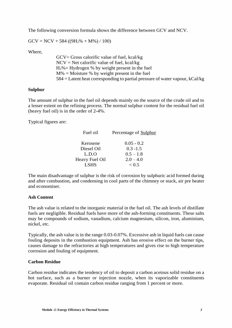
The following conversion formula shows the difference between GCV and NCV.
GCV = NCV + 584 ((9H2% + M%) / 100)
Where,
GCV= Gross calorific value of fuel, kcal/kg
NCV = Net calorific value of fuel, kcal/kg
H2%= Hydrogen % by weight present in the fuel
M% = Moisture % by weight present in the fuel
584 = Latent heat corresponding to partial pressure of water vapour, kCal/kg
Sulphur
The amount of sulphur in the fuel oil depends mainly on the source of the crude oil and to
a lesser extent on the refining process. The normal sulphur content for the residual fuel oil
(heavy fuel oil) is in the order of 2-4%.
Typical figures are:
Fuel oil Percentage of Sulphur
Kerosene 0.05 - 0.2
Diesel Oil 0.3 -1.5
L.D.O 0.5 – 1.8
Heavy Fuel Oil 2.0 – 4.0
LSHS ˂ 0.5
The main disadvantage of sulphur is the risk of corrosion by sulphuric acid formed during
and after combustion, and condensing in cool parts of the chimney or stack, air pre heater
and economiser.
Ash Content
The ash value is related to the inorganic material in the fuel oil. The ash levels of distillate
fuels are negligible. Residual fuels have more of the ash-forming constituents. These salts
may be compounds of sodium, vanadium, calcium magnesium, silicon, iron, aluminium,
nickel, etc.
Typically, the ash value is in the range 0.03-0.07%. Excessive ash in liquid fuels can cause
fouling deposits in the combustion equipment. Ash has erosive effect on the burner tips,
causes damage to the refractories at high temperatures and gives rise to high temperature
corrosion and fouling of equipment.
Carbon Residue
Carbon residue indicates the tendency of oil to deposit a carbon acetous solid residue on a
hot surface, such as a burner or injection nozzle, when its vaporizable constituents
evaporate. Residual oil contain carbon residue ranging from 1 percent or more.
Module -2: Energy Efficiency in Thermal Systems 4
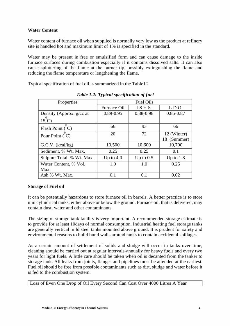
Water Content
Water content of furnace oil when supplied is normally very low as the product at refinery
site is handled hot and maximum limit of 1% is specified in the standard.
Water may be present in free or emulsified form and can cause damage to the inside
furnace surfaces during combustion especially if it contains dissolved salts. It can also
cause spluttering of the flame at the burner tip, possibly extinguishing the flame and
reducing the flame temperature or lengthening the flame.
Typical specification of fuel oil is summarized in the Table1. 2.
Table 1.2: Typical specification of fuel
Properties Fuel Oils
Furnace Oil LS.H.S. L.D.O.
Density (Approx. g/cc at
150
C)
0.89-0.95 0.88-0.98 0.85-0.87
Flash Point (0
C) 66 93 66
Pour Point (0
C) 20 72 12 (Winter)
18 (Summer)
G.C.V. (kcal/kg) 10,500 10,600 10,700
Sediment, % Wt. Max. 0.25 0.25 0.1
Sulphur Total, % Wt. Max. Up to 4.0 Up to 0.5 Up to 1.8
Water Content, % Vol.
Max.
1.0 1.0 0.25
Ash % Wt. Max. 0.1 0.1 0.02
Storage of Fuel oil
It can be potentially hazardous to store furnace oil in barrels. A better practice is to store
it in cylindrical tanks, either above or below the ground. Furnace oil, that is delivered, may
contain dust, water and other contaminants.
The sizing of storage tank facility is very important. A recommended storage estimate is
to provide for at least 10days of normal consumption. Industrial heating fuel storage tanks
are generally vertical mild steel tanks mounted above ground. It is prudent for safety and
environmental reasons to build bund walls around tanks to contain accidental spillages.
As a certain amount of settlement of solids and sludge will occur in tanks over time,
cleaning should be carried out at regular intervals-annually for heavy fuels and every two
years for light fuels. A little care should be taken when oil is decanted from the tanker to
storage tank. All leaks from joints, flanges and pipelines must be attended at the earliest.
Fuel oil should be free from possible contaminants such as dirt, sludge and water before it
is fed to the combustion system.
Loss of Even One Drop of Oil Every Second Can Cost Over 4000 Litres A Year

Module -2: Energy Efficiency in Thermal Systems 5
Removal of Contaminants
Furnace oil arrives at the factory site either in tank lorries by road or by rail. Oil is then
decanted into the main storage tank. To prevent contaminants such as rags, cotton waste,
loose nuts or bolts or screws entering the system and damaging the pump, coarse strainer
of 10 mesh size (not more than 3 holes per linear inch) is positioned on then try pipe to the
storage tanks.
Progressively finer strainers should be provided at various points in the oil supply system
to filter away finer contaminants such as external dust and dirt, sludge or free carbon. It is
advisable to provide these filters in duplicate to enable one filter to be cleaned while oil
supply is maintained through the other.
The Figure1.1 gives an illustration of the duplex system of arrangement of strainers.
Figure1.1: Duplex arrangement of strainers in a pipeline
The Table 1.3 gives sizing of strainers at various locations.
Table 1.3: Sizing of strainers at various locations
Location Strainer Sizes
Mesh Holes / Linear inch
Between rail / tank lorry decanting
point and main storage tank
10 3
Between service tank and pre-heater 40 6
Between pre-heater and burner 100 10
Pumping
Heavy fuel oils are best pumped using positive displacement pumps, as they are able to
get fuel moving when it is cold. A circulation gear pump running on LDO should give
between 7000-10000 hours of service. Diaphragm pump shave a shorter service life, but
are easier and less expensive to repair. A centrifugal pump is not recommended, because
as the oil viscosity increases, the efficiency of the pump drops sharply and the horse power
required increases. Light fuels are best pumped with centrifugal or turbine pumps. When
higher pressures are required, piston or diaphragm pumps should be used.
Storage Temperature and Pumping Temperature
The viscosity of furnace oil and LSHS increases with decrease in temperature, which
makes it difficult to pump the oil. At low ambient temperatures (below 25 0C), furnace oil

Module -2: Energy Efficiency in Thermal Systems 6
is not easily pumpable. To circumvent this, preheating of oil is accomplished in two ways:
a) the entire tank may be preheated. In this form of bulk heating, steam coils are placed at
the bottom of the tank, which is fully insulated; b) the oil can be heated as it flows out with
an outflow heater. To reduce steam requirements, it is advisable to insulate tanks where
bulk heating is used.
Bulk heating may be necessary if flow rates are high enough to make outflow heaters of
adequate capacity impractical, or when a fuel such as Low Sulphur Heavy Stock (LSHS)
is used. In the case of out flow heating, only the oil, which leaves the tank, is heated to the
pumping temperature. The out flow heater is essentially a heat exchanger with steam or
electricity as the heating medium.
Temperature Control
Thermostatic temperature control of the oil is necessary to prevent overheating, especially
when oil flow is reduced or stopped. This is particularly important for electric heaters,
since oil may get carbonized when there is no flow and the heater is on. Thermostats should
be provided at a region where the oil flows freely into the suction pipe. The temperature
at which oil can readily be pumped depends on the grade of oil being handled. Oil should
never be stored at a temperature above that necessary for pumping as this leads to higher
energy consumption.
1.3 Properties of Coal
Coal Classification
In general there are three main types of coal: anthracite, bituminous, and lignite, but no
clear-cutline exists between them and coal is further classed as semi anthracite, semi
bituminous, and sub bituminous. Anthracite is the oldest form of coal, geologically
speaking. It is a hard coal composed mainly of carbon with little volatile content and
practically no moisture. Lignite is the youngest form of coal, composed mainly of volatile
matter and moisture content with low fixed carbon content. Fixed carbon refers to carbon
in its free state, not combined with other elements. Volatile matter refers to those
combustible constituents of coal that vaporize when coal is heated.
The chemical composition of coal has a strong influence on its combustibility. The
properties of coal are broadly classified as
Physical properties
Chemical properties
Physical Properties
Heating Value
The heating value of coal varies from country to country and even from mine to mine
within the same country. The typical GCVs for various coals are given in the Table1.4.
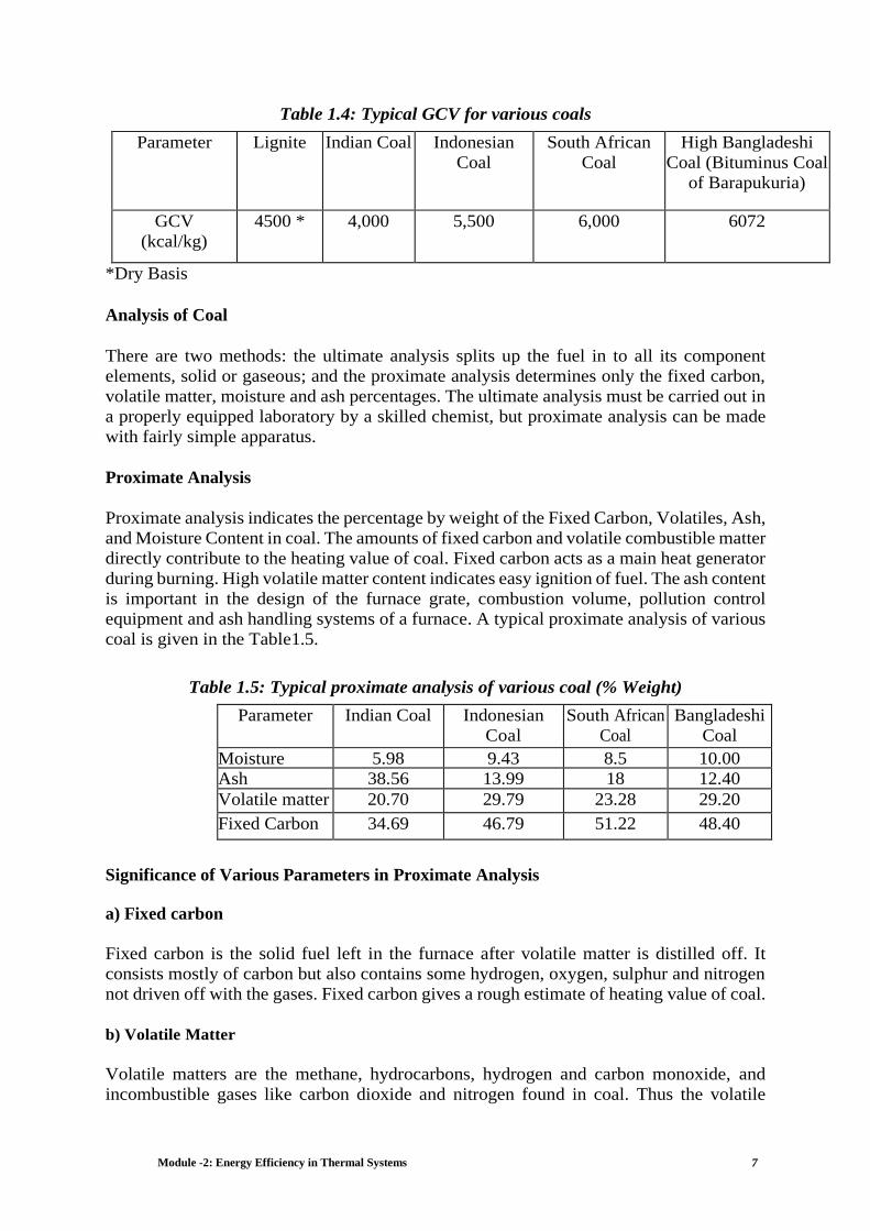
Module -2: Energy Efficiency in Thermal Systems 7
Table 1.4: Typical GCV for various coals
Parameter Lignite Indian Coal Indonesian
Coal
South African
Coal
High Bangladeshi
Coal (Bituminus Coal
of Barapukuria)
GCV
(kcal/kg)
4500 * 4,000 5,500 6,000 6072
*Dry Basis
Analysis of Coal
There are two methods: the ultimate analysis splits up the fuel in to all its component
elements, solid or gaseous; and the proximate analysis determines only the fixed carbon,
volatile matter, moisture and ash percentages. The ultimate analysis must be carried out in
a properly equipped laboratory by a skilled chemist, but proximate analysis can be made
with fairly simple apparatus.
Proximate Analysis
Proximate analysis indicates the percentage by weight of the Fixed Carbon, Volatiles, Ash,
and Moisture Content in coal. The amounts of fixed carbon and volatile combustible matter
directly contribute to the heating value of coal. Fixed carbon acts as a main heat generator
during burning. High volatile matter content indicates easy ignition of fuel. The ash content
is important in the design of the furnace grate, combustion volume, pollution control
equipment and ash handling systems of a furnace. A typical proximate analysis of various
coal is given in the Table1.5.
Table 1.5: Typical proximate analysis of various coal (% Weight)
Parameter Indian Coal Indonesian
Coal
South African
Coal
Bangladeshi
Coal
Moisture 5.98 9.43 8.5 10.00
Ash 38.56 13.99 18 12.40
Volatile matter 20.70 29.79 23.28 29.20
Fixed Carbon 34.69 46.79 51.22 48.40
Significance of Various Parameters in Proximate Analysis
a) Fixed carbon
Fixed carbon is the solid fuel left in the furnace after volatile matter is distilled off. It
consists mostly of carbon but also contains some hydrogen, oxygen, sulphur and nitrogen
not driven off with the gases. Fixed carbon gives a rough estimate of heating value of coal.
b) Volatile Matter
Volatile matters are the methane, hydrocarbons, hydrogen and carbon monoxide, and
incombustible gases like carbon dioxide and nitrogen found in coal. Thus the volatile

Module -2: Energy Efficiency in Thermal Systems 8
matter is an index of the gaseous fuels present. Typical range of volatile matter is 20 to
35%.
Volatile Matter
Proportionately increases flame length, and helps in easier ignition of coal.
Sets minimum limit on the furnace height and volume.
Influences secondary air requirement and distribution aspects.
c) Ash Content
Ash is an impurity that will not burn. Typical range is 0.5 to 40%.
Ash reduces handling and burning capacity.
Increases handling costs
Affects combustion and boiler efficiency
Causes clinkering and slagging
d) Moisture Content
Moisture in coal must be transported, handled and stored. Since it replaces combustible
matter, it decreases the heat content per kg of coal. Typical range is 0.5 to10%.
Moisture
Increases heat loss, due to evaporation and superheating of vapour
Helps, to a limit, in binding fines.
Aids radiation heat transfer.
e) Sulphur Content
Typical range is 0.5 to 5%.
Sulphur
Affects clinkering and slagging tendencies
Corrodes chimney and other equipment such as air heaters and economisers
Limits exit flue gas temperature.
Chemical Properties
Ultimate Analysis:
The ultimate analysis indicates the various elemental chemical constituents such as
Carbon, Hydrogen, Oxygen, Sulphur, etc. It is useful in determining the quantity of air
required for combustion and the volume and composition of the combustion gases. This
information is required for the calculation of flame temperature and the flue duct design
etc. Typical ultimate analyses of various coals are given in the Table1.6.

Module -2: Energy Efficiency in Thermal Systems 9
Table 1.6: Ultimate analyses of various coals
Parameter Lignite,% Indian Coal,% Indonesian Coal,% Bangladeshi Coal,%
Moisture (Dry)
basis)
50 5.98 9.43 10 Mineral Matter 10.41 38.63 13.99 20.49 Carbon 62.01 41.11 58.96 61.52 Hydrogen 6.66 2.76 4.16 3.87 Nitrogen 0.60 1.22 1.02 1.52 Sulphur 0.59 0.41 0.56 0.53 Oxygen 19.73 9.89 11.88 12.07
Relationship Between Ultimate Analysis and Proximate Analysis
%C = 0.97C+ 0.7(VM - 0.1A) - M(0.6-0.01M)
%H = 0.036C + 0.086 (VM -0.1xA) - 0.0035M2
(1-0.02M)
%N2 = 2.10 -0.020 VM
Where
C = % of fixed carbon
A = % of ash
VM = % of volatile matter
M = % of moisture
Storage, Handling and Preparation of Coal
Uncertainty in the availability and transportation of fuel necessitates storage and
subsequent handling. Stocking of coal has its own disadvantages like build-up of
inventory, space constraints, deterioration in quality and potential fire hazards. Other
minor losses associated with the storage of coal include oxidation, wind and carpet loss. A
1% oxidation of coal has the same effect as 1% ash in coal, wind losses may account for
nearly 0.5-1.0% of the total loss.
The main goal of good coal storage is to minimize carpet loss and the loss due to
spontaneous combustion. Formation of a soft carpet, comprising of coal dust and soil
causes carpet loss. On the other hand, gradual temperature builds up in a coal heap, on
account oxidation may lead to spontaneous combustion of coal in storage.
The measures that would help in reducing the carpet loses are as follows:
1. Preparing a hard ground for coal to be stacked upon.
2. Preparing standard storage bays out of concrete and brick
In process Industry, modes of coal handling range from manual to conveyor systems. It
would be advisable to minimize the handling of coal so that further generation of fines and
segregation effects are reduced.
Preparation of Coal
Preparation of coal prior to feeding in to the boiler is an important step for achieving good
combustion. Large and irregular lumps of coal may cause the following problems:
1. Poor combustion conditions and inadequate furnace temperature.

Module -2: Energy Efficiency in Thermal Systems 10
2. Higher excess air resulting in higher stack loss.
3. Increase of unburnt in the ash.
4. Low thermal efficiency.
Sizing of Coal
Proper coal sizing is one of the key measures to ensure efficient combustion. Proper coal
sizing, with specific relevance to the type of firing system, helps towards even burning,
reduced ash losses and better combustion efficiency.
Coal is reduced in size by crushing and pulverizing. Pre-crushed coal can be economical
for smaller units, especially those which are stoker fired. In a coal handling system,
crushing is limited to a top size of 6 or 4 mm. The devices most commonly used for
crushing are the rotary breaker, the roll crusher and the hammer mill.
It is necessary to screen the coal before crushing, so that only oversized coal is fed to the
crusher. This helps to reduce power consumption in the crusher. Recommended practices
in coal crushing are:
1. Incorporation of a screen to separate fines and small particles to avoid extra fine
generation in crushing.
2. Incorporation of a magnetic separator to separate iron pieces in coal, which may
damage the crusher.
The Table 1.7 gives the proper size of coal for various types of firing systems
Table 1.7: Proper size of coal for various types of firing systems
S. No. Types of Firing System Size (in mm)
1 Hand Firing
(a) Natural draft
(b) Forced draft
25-75
25-40
2 Stoker Firing
(a) Chain grate
i) Natural draft
ii) Forced draft
(b) Spreader Stoker
25-40
15-25
15-25
3 Pulverized Fuel Fired 75% below 75 micron*
4 Fluidized bed boiler < 10 mm
*Micron = 1/1000mm
a) Conditioning of Coal
The fines present in coal create problems in combustion due to segregation effects.
Segregation of fines from larger coal pieces can be reduced to a great extent by
conditioning coal with water. Water helps fine particles to stick to the bigger lumps due to
surface tension of the moisture, thus stopping fines from falling through grate bars or being
carried away by the furnace draft. While tempering the coal, care should be taken to ensure
that moisture addition is uniform and preferably done in a moving or falling stream of coal.

Module -2: Energy Efficiency in Thermal Systems 11
If the percentage of fines in the coal is very high, wetting of coal can decrease the
percentage of unburnt carbon and the excess air level required to be supplied for
combustion. Table 1.8 shows the extent of wetting, depending on the percentage of fines
in coal.
Table 1.8: Extent of wetting, depending on the percentage of fines in coal
Fines (%) Surface Moisture
(%)
10 - 15 4 - 5
15 - 20 5 - 6
20 - 25 6 - 7
25 - 30 7 - 8
b) Blending of Coal
In case of coal lots having excessive fines, it is advisable to blend the predominantly
lumped coal with lots containing excessive fines. Coal blending may thus help to limit the
extent of fines in coal being fired to not more than 25%. Blending of different qualities of
coal may also help to supply uniform coal feed to the boiler.
The proximate and ultimate analyses of various coals are given inTable1.9 and1.10.
Table 1.9: Proximate analysis of various coals
Lecfines Lignite Indian
Coal
(type 1)
Indian Coal
(type 2)
Indonesian
Coal
South
African Coal
Moisture (%) 9.92 49.79 5.98 4.39 9.43 8.5
Ash (%) 5.93 10.41 38.65 47.86 13.99 18
Volatile matter
(%)
24.08 47.76 20.70 17.97 29.79 23.28
Fixed Carbon (%) 60.70 41.83 34.69 29.78 46.79 51.22
Table 1.10: Ultimate analysis of various coals
Lecofines Lignite Indian Coal
(type 2)
Indian Coal
(type 2)
Indonesian Coal
Moisture (%) 9.92 Dry basis 5.98 4.39 9.43
Mineral matter (%) 5.93 10.41 38.63 47.86 13.99
Carbon (%) 71.02 62.01 42.11 36.22 58.96
Hydrogen (%) 3.33 6.66 2.76 2.64 4.16
Nitrogen (%) 0.96 0.60 1.22 1.09 1.02
Sulphur (%) 0.55 0.59 0.41 0.55 0.56
Oxygen (%) 8.29 19.73 9.89 7.25 11.88
GCV(kCal/kg) 7242 6301 4000 3500 5500

Module -2: Energy Efficiency in Thermal Systems 12
1.4 Properties of Gaseous Fuels
Gaseous fuels in common use are liquefied petroleum gases (LPG), Natural gas, producer
gas, blast furnace gas, coke oven gas etc. The calorific value of gaseous fuel is expressed
in Kilocalories per cubic meter (kcal/Nm3) i.e. at normal temperature and pressure.
Calorific Value
Since most gas combustion appliances cannot utlilize the heat content of the water vapour,
gross calorific value is of little interest. Fuel should be compared based on the net calorific
value. This is especially true for natural gas, since increased hydrogen content results in
high water formation during combustion.
Typical physical and chemical properties of various gaseous fuels are given inTable1.11.
Table 1.11: Typical physical and chemical properties of various gaseous fuels
Fuel Gas Relative
Density
Higher Heating
Value, kCal/Nm3
Air/Fuel ratio,
m3 of air to m3
of Fuel
Flame
Temp., oC
Flame Speed,
m/s
Natural Gas 0.6 9350 10 1954 0.290
Propane 1.52 22200 25 1967 0.460
Butane 1.96 28500 32 1973 0.870
LPG
LPG is a predominant mixture of propane and Butane with a small percentage of
unsaturated (Propylene and Butylene) and some lighter C2 as well as heavier C5 fractions.
Included in the LPG range are propane (C3H8), Propylene (C3H6), normal and iso-butane
(C4H10) and Butylene (C4H8).
LPG may be defined as those hydrocarbons which are gaseous at normal atmospheric
pressure, but may be condensed to the liquid state at normal temperature, by the application
of moderate pressures. Although they are normally used as gases, they are stored and
transported as liquids under pressure for convenience and ease of hand ling. Liquid LPG
evaporates to produce about 250 times volume of gas.
LPG vapour is denser than air: butane is about twice as heavy as air and propane about one
and a half time as heavy as air. Consequently, the vapour may flow along the ground and
into drains sinking to the lowest level of the surroundings and be ignited at a considerable
distance from the source of leakage. In still air vapour will disperse slowly. Escape of even
small quantities of the liquefied gas can give rise to large volumes of vapour / air mixture
and thus cause considerable hazard. To aid in the detection of atmospheric leaks, all LPG’s
are required to be odorized. There should be adequate ground level ventilation where LPG
is stored. For this very reason, LPG cylinders should not be stored in cellars or basements,
which have no ventilation at ground level.
Natural Gas
Methane is the main constituent of Natural gas and accounting for about 97% of the total
volume. Other components are: Ethane, Propane, Butane, Pentane, Nitrogen, Carbon

Module -2: Energy Efficiency in Thermal Systems 13
Dioxide, and traces of other gases. Very small amounts of sulphur compounds are also
present. Since methane is the largest component of natural gas, generally properties of
methane are used when comparing the properties of natural gas to other fuels.
Natural gas is a high calorific value fuel requiring no storage facilities. It mixes with air
readily and does not produce smoke or soot. It has no sulphur content. It is lighter than air
and disperses in to air easily in case of leak. A typical comparison of carbon contents in
oil, coal and gas is given in the table1.12.
Table 1.12: Comparison of carbon contents in oil, coal and gas
Fuel Oil Coal Natural Gas
Carbon 84 41.11 74
Hydrogen 12 2.76 25
Sulphur 3 0.41 -
Oxygen 1 9.89 Trace
Nitrogen Trace 1.22 0.75
Ash Trace 38.63 -
Water Trace 5.98 -
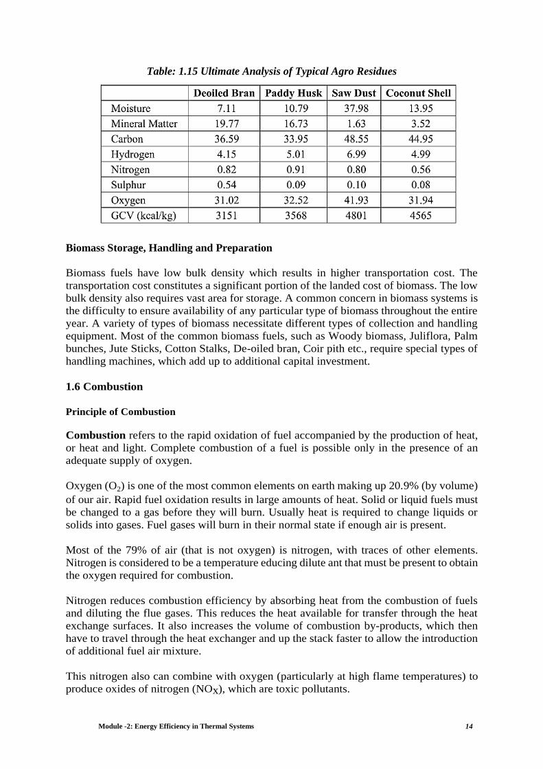
1.5 Properties of Agro Residues
The use of locally available agro residues is on the rise. This includes rice husk, coconut
shells, groundnut shells, Coffee husk, Wheat stalk etc. The properties of a few of them are
given in the table1.13.
Table 1.13: Properties of Agro Residues
De oiled Bran Paddy Husk Saw Dust Coconut Shell
Moisture 7.11 10.79 37.98 13.95
Ash 18.46 16.73 1.63 3.52
Volatile Matter 59.81 56.46 81.22 61.91
Fixed Carbon 14.62 16.02 17.15 20.62
Mineral Matter 19.77 16.73 1.63 3.52
Carbon 36.59 33.95 48.55 44.95
Hydrogen 4.15 5.01 6.99 4.99 Nitrogen 0.82 0.91 0.80 0.56
Sulphur 0.54 0.09 0.10 0.08 Oxygen 31.02 32.52 41.93 31.94
GCV(kCal/kg) 3151 3568 4801 4565
Table1.14: Proximate Analysis of Typical Agro Resudies
Module -2: Energy Efficiency in Thermal Systems 14
Table: 1.15 Ultimate Analysis of Typical Agro Residues
Biomass Storage, Handling and Preparation
Biomass fuels have low bulk density which results in higher transportation cost. The
transportation cost constitutes a significant portion of the landed cost of biomass. The low
bulk density also requires vast area for storage. A common concern in biomass systems is
the difficulty to ensure availability of any particular type of biomass throughout the entire
year. A variety of types of biomass necessitate different types of collection and handling
equipment. Most of the common biomass fuels, such as Woody biomass, Juliflora, Palm
bunches, Jute Sticks, Cotton Stalks, De-oiled bran, Coir pith etc., require special types of
handling machines, which add up to additional capital investment.
1.6 Combustion
Principle of Combustion
Combustion refers to the rapid oxidation of fuel accompanied by the production of heat,
or heat and light. Complete combustion of a fuel is possible only in the presence of an
adequate supply of oxygen.
Oxygen (O2) is one of the most common elements on earth making up 20.9% (by volume)
of our air. Rapid fuel oxidation results in large amounts of heat. Solid or liquid fuels must
be changed to a gas before they will burn. Usually heat is required to change liquids or
solids into gases. Fuel gases will burn in their normal state if enough air is present.
Most of the 79% of air (that is not oxygen) is nitrogen, with traces of other elements.
Nitrogen is considered to be a temperature educing dilute ant that must be present to obtain
the oxygen required for combustion.
Nitrogen reduces combustion efficiency by absorbing heat from the combustion of fuels
and diluting the flue gases. This reduces the heat available for transfer through the heat
exchange surfaces. It also increases the volume of combustion by-products, which then
have to travel through the heat exchanger and up the stack faster to allow the introduction
of additional fuel air mixture.
This nitrogen also can combine with oxygen (particularly at high flame temperatures) to
produce oxides of nitrogen (NOx), which are toxic pollutants.
Module -2: Energy Efficiency in Thermal Systems 15
Carbon, hydrogen and sulphur in the fuel combine with oxygen in the air to form carbon
di oxide, water vapour and sulphur dioxide, releasing 8084, 28922 and 2224 kcal of heat
respectively. Under certain conditions, Carbon may also combine with Oxygen to form
Carbon Monoxide, which results in the release of a smaller quantity of heat (2430 kcal/ kg
of carbon) Carbon burned to CO2 will produce more heat per pound of fuel than when CO
or smoke are produced.
C + O2 → CO 2 + 8084 kcal/kg of Carbon
2C + O2 → 2 CO + 2430 kcal/kg of Carbon
2H2 + O2 → 2H2O + 28,922 kcal/kg of Hydrogen
S + O2 → SO2 + 2,224 kcal/kg of Sulphur
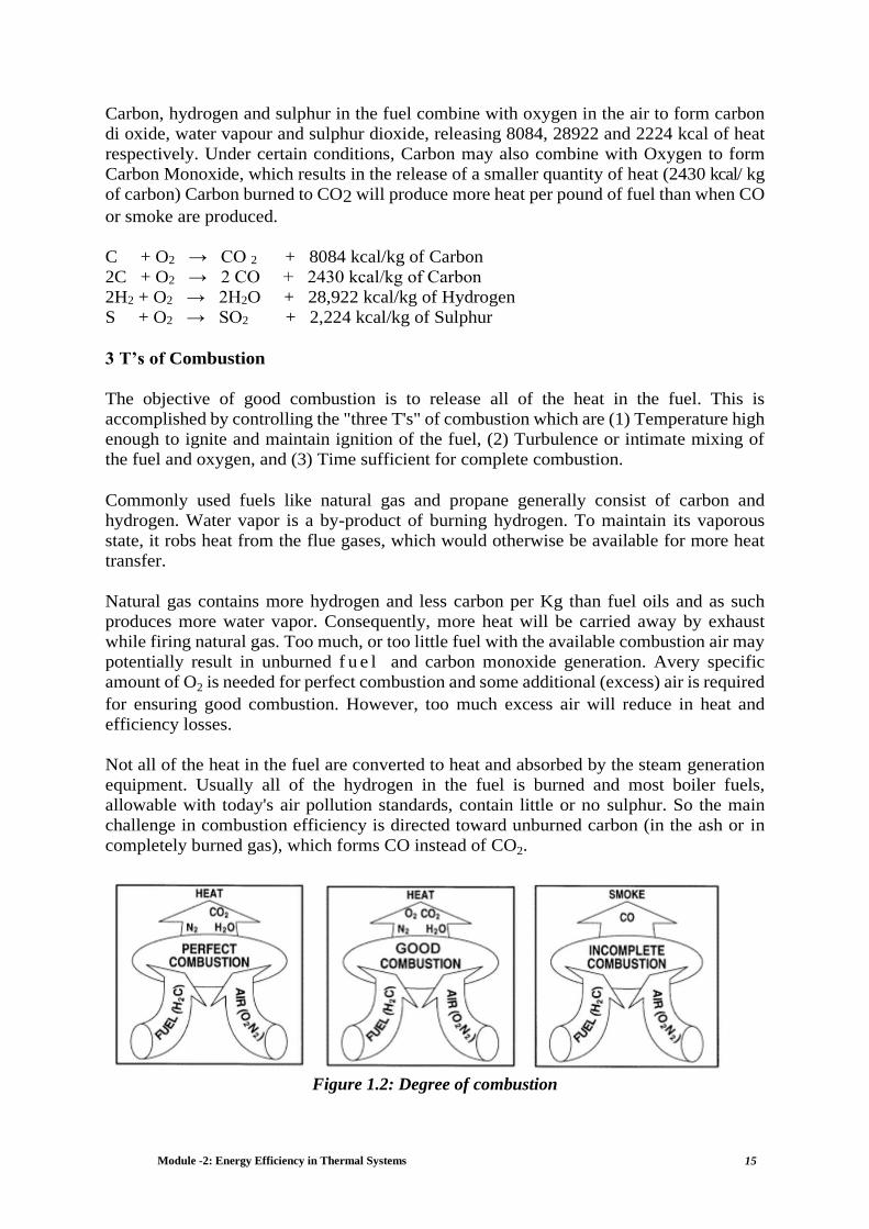
3 T’s of Combustion
The objective of good combustion is to release all of the heat in the fuel. This is
accomplished by controlling the "three T's" of combustion which are (1) Temperature high
enough to ignite and maintain ignition of the fuel, (2) Turbulence or intimate mixing of
the fuel and oxygen, and (3) Time sufficient for complete combustion.
Commonly used fuels like natural gas and propane generally consist of carbon and
hydrogen. Water vapor is a by-product of burning hydrogen. To maintain its vaporous
state, it robs heat from the flue gases, which would otherwise be available for more heat
transfer.
Natural gas contains more hydrogen and less carbon per Kg than fuel oils and as such
produces more water vapor. Consequently, more heat will be carried away by exhaust
while firing natural gas. Too much, or too little fuel with the available combustion air may
potentially result in unburned f u e l and carbon monoxide generation. Avery specific
amount of O2 is needed for perfect combustion and some additional (excess) air is required
for ensuring good combustion. However, too much excess air will reduce in heat and
efficiency losses.
Not all of the heat in the fuel are converted to heat and absorbed by the steam generation
equipment. Usually all of the hydrogen in the fuel is burned and most boiler fuels,
allowable with today's air pollution standards, contain little or no sulphur. So the main
challenge in combustion efficiency is directed toward unburned carbon (in the ash or in
completely burned gas), which forms CO instead of CO2.
Figure 1.2: Degree of combustion

Module -2: Energy Efficiency in Thermal Systems 16
1.7 Combustion of Oil
Heating Oil to Correct Viscosity
When atomizing oil, it is necessary to heat it enough to get the desired viscosity. This
temperature varies slightly for each grade of oil. The lighter oils do not usually require
pre-heating. Typical viscosity at the burner tip (for LAP, MAP & HAP burners) for furnace
oil should be 100 Redwood seconds-1 which would require heating the oil to about 1050C.
Stoichiometric Combustion
The efficiency of a boiler or furnace depends on efficiency of the combustion system. The
amount of air required for complete combustion of the fuel depends on the elemental
constituents of the fuel that is Carbon, Hydrogen, and Sulphur etc. This amount of air is
called stanchion metric air. For ideal combustion process for burning one kg of a typical
fuel oil containing 86% Carbon, 12% Hydrogen, 2% Sulphur, theoretically required
quantity of air is 14.1kg. This is the minimum air that would be required if mixing of fuel
and air by the burner and combustion is perfect. The combustion products are primarily
Carbon Dioxide (CO2), water vapor (H2O) and Sulphur Dioxide (SO2), which pass through
the chimney along with the Nitrogen (N2) in the air.
Rules for combustion of oil
Atomise the oil completely to produce a fine spray
Mix the air and fuel thoroughly
Introduce enough air for combustion, but limit the excess air to a maximum of 15%
Keep the burners in good condition
After surrendering useful heat in the heat absorption area of a furnace or boiler, the
combustion products or fuel gases leave the system through the chimney, carrying a way
a significant quantity of heat with them.
Calculation of Stoichiometric Air
The specification of furnace oil from lab analysis is given below:
Constituents % By weight
Carbon 85.9
Hydrogen 12
Oxygen 0.7
Nitrogen 0.5
Sulphur 0.5
H2O 0.35
Ash 0.05
GCV of fuel: 10880 kCal/kg

Module -2: Energy Efficiency in Thermal Systems 17
Calculation for Requirement of Theoretical Amount of Air
Considering a sample of 100kg of furnace oil. The chemical reactions are:
Element Molecular Weight
kg / kg mole
C 12
O2 32
H2 2
S 32
N2 28
CO2 44
SO2 64
H2O 18
C + O2 → CO2
H2 + ½ O2 → H2O
S + O2 → SO2
Constituents of fuel
C + O2 → CO2
12 + 32 → 44
12 kg of carbon requires 32 kg of oxygen to form 44 kg of carbon dioxide therefore 1 kg
of carbon requires 32/12 kg i.e 2.67 kg of oxygen
(85.9) C + (85.9 x 2.67) O2 314.97 CO2
2H2 + O2 2H2O
4 + 32 36
4 kg of hydrogen requires 32 kg of oxygen to form 36 kg of water, therefore 1 kg of
hydrogen requires 32/4 kg i.e 8 kg of oxygen
(12) H2 + (12 x 8) O2 (12 x 9) H2O
S + O2 → SO2
32 + 32 → 64
32 kg of sulphur requires 32 kg of oxygen to form 64 kg of sulphur dioxide, therefore 1 kg
of sulphur requires 32/32 kg i.e 1 kg of oxygen
(0.5) S + (0.5 x 1) O2 1.0 SO2

Module -2: Energy Efficiency in Thermal Systems 18
Total Oxygen required = 325.57 kg
(229.07+96+0.5)
Oxygen already present in
100 kg fuel (given) = 0.7 kg
Additional Oxygen Required = 325.57 – 0.7
= 324.87 kg
Therefore quantity of dry air reqd. = (324.87) / 0.23
(air contains 23% oxygen by wt.)
= 1412.45 kg of air
Theoretical Air required = (1412.45) / 100
= 14.12 kg of air / kg of fuel
Calculation of theoretical CO2 content in flue gases
Nitrogen in flue gas = 1412.45 – 324.87 + 0.5
= 1088.08 kg
Theoretical CO2% in dry flue gas by volume is calculated as below:
Moles of CO2 in flue gas = (314.97) / 44 = 7.16
Moles of N2 in flue gas = (1088.08) / 28 = 38.86
Moles of SO2 in flue gas = 1/64 = 0.016
100)(
% 22 x
drymolesTotal
COofMolesvolumebyCOlTheoritica
100x016.086.3816.7
16.7
= 15.6 %
Calculation of constituents of flue gas with excess air
% CO2 measured in flue gas = 10% (measured)
% Excess air supplied (EA) = ]%)(100[%)(
]%)(%)[(7900
22
22
ta
at
COxCO
COCOx
% Excess air supplied (EA) = ]6.15100[x10
]106.15[x7900
= 52.4%
Theoretical air required for 100 kg
of fuel burnt
= 1412.45 kg

Module -2: Energy Efficiency in Thermal Systems 19
Total quantity. of air supply required
with 52.4% excess air
= 1412.45 X 1.524
= 2152.57 kg
Excess air quantity = 2152.57 – 1412.45
= 740.12 kg.
O2 = 740.12 X 0.23
= 170.23 kg
N2 = 740.12 – 170.23
= 570 kg
The final constitution of flue gas with 52.4% excess air for every 100 kg fuel.
CO2 = 314.97 kg
H2O = 108.00 kg
SO2 = 1 kg
O2 = 170.23 kg
N2 = 1088.08 + 570
= 1658.08 kg
Determination of Actual CO2% by calculation in dry flue gas by volume
Moles of CO2 in flue gas = 314.97/44 = 7.16
Moles of SO2 in flue gas = 1/64 = 0.016
Moles of O2 in flue gas = 170.23 / 32 = 5.32
Moles of N2 in flue gas = 1658.08 / 28 = 59.22
100x(dry)molesTotal
COofMolesvolumeby%COActual 2
2
100x22.5932.5016.016.7
16.7
100x716.71
16.7
= 10%
Actual O2% by volume %42.7100x716.71
100x32.5
Optimizing Excess Air and Combustion
For complete combustion of every one kg of fuel oil 14.1 kg of air is needed. In practice,
mixing is never perfect, a certain amount of excess air is needed to complete combustion
and ensure that release of the entire heat contained in fuel oil. If too much air than what is
required for completing combustion were allowed to enter, additional heat would be lost
in heating the surplus air to the chimney temperature. This would result in increased stack

Module -2: Energy Efficiency in Thermal Systems 20
losses. Less air would lead to the incomplete combustion and smoke. Hence, there is an
optimum excess air level for each type of fuel.
Control of Air and Analysis of Flue Gas
Thus in actual practice, the amount of combustion air required will be much higher than
optimally needed. Therefore some of the air gets heated in the furnace boiler and leaves
through the stack without participating in the combustion.
Chemical analysis of the gases is an objective method that helps in achieving finer air
control. By measuring carbon dioxide (CO2) or oxygen (O2) in flue gases by continuous
recording instruments or Orsat apparatus or some cheaper portable instruments, the excess
air level as well as stack losses can be estimated with the graph as shown in Figure 1.2 and
Figure 1.3. The excess air to be supplied depends on the type of fuel and the firing system.
For optimum combustion of fuel oil, the CO2 or O2 in flue gases should be maintained at
14-15% in case of CO2 and 2-3% in case of O2 measurement.
Figure 1.2: Relation between CO2 and excess air for fuel oil
Figure 1.3: Relation between residual oxygen and excess air Oil Firing Burners
The burner is the principal device for the firing of the fuel. The primary function of burner
is to atomise fuel to millions of small droplets so that the surface area of the fuel is
increased enabling intimate contact with oxygen in air. The finer the fuel drop lets are
250
100
2 3 4 5 6 7 8 9
100
8.4
10
11
12
13
14
15
Exce
ss A
ir %
Exce
ss A
ir %

Module -2: Energy Efficiency in Thermal Systems 21
atomised, more readily will the particles come in contact with the oxygen in the air and
burn.
Normally, atomization is carried out by primary air and completion of combustion is
ensured by secondary air. Burners for fuel oil can be classified on a basis of the technique
to prepare the fuel for burning i.e. atomization.
Figure1.4 shows a simplified burner head. The air is brought in to the head by means of a
forced draft blower or fan. The gas is metered into the head through a series of valves. In
order to get proper combustion, the air molecules must be thoroughly mixed with the gas
molecules before they actually burn.
The mixing is achieved by burner parts designed to create high turbulence. If insufficient
turbulence is produced by the burner, the combustion will be incomplete and samples taken
at the stack will reveal carbon monoxide as evidence.
Figure 1.4: Burner head
Since the velocity of air affects the turbulence, it becomes harder and harder to get good
fuel and air mixing at higher turn down ratios since the air amount is reduced. Towards
the highest turndown ratios of any burner, it becomes necessary to increase the excess air
amounts to obtain enough turbulence to get proper mixing. The better burner design will
be one that is able to properly mix the air and fuel at the lowest possible air flow or excess
air.
An important aspect to be considered in selection of burner is turn down ratio. Turn down
ratio is the relationship between the maximum and minimum fuel input without affecting
the excess air level. For example, a burner whose maximum input is 250,000 kcal and
minimum rate is 50,000 kcal, has a ‘Turn-Down Ratio’ of 5 to1.
The air in the center is the primary air which is used for atomization and the one
surrounding is the secondary air which ensures complete combustion.
1.8 Combustion of Coal
Features of coal combustion
1kg of coal will typically require 7-8 kg of air depending upon the carbon, hydrogen,
nitrogen, oxygen and sulphur content for complete combustion. This air is also known as
theoretical or stoichiometric air.

Module -2: Energy Efficiency in Thermal Systems 22
If for any reason the air supplied is inadequate, the combustion will be incomplete. The
result is poor generation of heat with some portions of carbon remaining unburnt (black
smoke) and forming carbon monoxide instead of carbon dioxides.
Figure 1.5: Stoker fired boilers
In actual case No fuel can be completely burnt with stoichiometric quantity of air.
Complete combustion is not achieved unless an excess of air is supplied.
The excess air required for coal combustion depends on the type of coal firing equipment.
Hand fired boilers use large lumps of coal and hence need very high excess air. Stoker
fired boilers as shown in the figure 5 use sized coal and hence requires less excess air. Also
in these systems primary air is supplied below the grate and secondary air is supplied over
the grate to ensure complete combustion.
Fluidized bed combustion in which turbulence is created leads to intimate mixing of air
and fuel resulting in further reduction of excess air. The pulverized fuel firing in which
powdered coal is fired has the minimum excess air due to high surface area of coal ensuring
complete combustion.
Clinker formation
Clinker is a mass of rough, hard, slag-like material formed during combustion of coat due
to low fusion temperature of ash present in coal. Presence of silica, calcium oxide,
magnesium oxides etc. in ash lead to a low fusion temperature. Typically Indian coals
contain ash fusion temperature as low as 1100oC. Once clinker is formed, it has a tendency
to grow. Clinker will stick to a hot surface rather than a cold one and to a rough surface
rather than a smooth one.

Module -2: Energy Efficiency in Thermal Systems 23
1.9 Combustion of Gas
Combustion Characteristics of Natural Gas
The stoichiometric ratio for natural gas (and most gaseous fuels) is normally indicated by
volume. The air to natural gas (stoichiometric) ratio by volume for complete combustion
vary between 9.5:1 to10:1
Natural gas is essentially pure methane, CH4. Its combustion can be represented as
follows:
CH4 + O2 = CO2 +2H2O
So for every 16 Kgs of methane that are consumed, 12 Kgs of carbon are released (as
carbon dioxide) and 44 Kgs of carbon dioxide are produced. (Remember that the atomic
weights of carbon, oxygen and hydrogen are 12, 16 and 1, respectively.)
Natural gas is primarily composed of methane, CH4. When mixed with the proper amount
of air and heated to the combustion temperature, it burns. Figure 1.6 shows the process
with the amount of air and fuel required for perfect combustion.
Figure 1.6: Combustion of natural gas
Low-And High-Pressure Gas Burners
The important thing in all gas-burning devices is a correct air-and-gas mixture at the burner
tip. Low-pressure burners (figure 1.7), using gas at a pressure less than 0.15 kg/cm2 (2 psi),
are usually of the multi jet type, in which gas from a manifold is supplied to a number of
small single jets, or circular rows of small jets, cantered in or discharging around the inner
circumference of circular air openings in a block of some heat-resisting material. The
whole is encased in a rectangular cast-iron box, built in to the boiler setting and having
louver doors front to regulate the air supply. Draft may be natural, induced, or forced.

Module -2: Energy Efficiency in Thermal Systems 24
Figure 1.7: Low pressure burner
In a high-pressure gas mixer (figure1.8), the energy of the gas jet draws air in to the mixing
chamber and delivers a correctly proportioned mixture to the burner. When the regulating
valve is opened, gas flows through a small nozzle into a venturine tube (a tube with a
contracted section). Entrainment of air with high-velocity gas in the narrow venture section
draws air in through large openings in the end. The gas-air mixture is piped to a burner.
The gas-burner tip may be in a variety of forms. In a sealed-in tip type, the proper gas-air
mixture is piped to the burner, and no additional air is drawn in around the burner tip. Size
of the air openings in the ventured been decreased by turning a revolving Sutter, which
can be locked in any desired position. Excess air level in natural gas burner is in the order
of 5%.
Figure 1.8: High pressure gas mixer
1.10 Combustion of Biomass
Biomass can be converted into energy (heat or electricity) or energy carriers (charcoal, oil,
or gas) using both thermochemical and biochemical conversion technologies. Combustion
is the most developed and most frequently applied process used for solid biomass fuels
because of its low costs and high reliability. During combustion, the biomass first loses its
moisture at temperatures up to 100°C, using heat from other particles that release their heat
value. As the dried particle heats up, volatile gases containing hydrocarbons, CO, CH4 and
other gaseous components are released. In a combustion process, these gases contribute
about 70% of the heating value of the biomass. Finally, char oxidises and ash remains. The
combustion installation needs to be properly designed for a specific fuel type in order to
guarantee adequate combustion quality and low emissions.

Module -2: Energy Efficiency in Thermal Systems 25
Figure 1.9: Combustion of Biomass in a Boiler
The characteristics and quality of biomass as a fuel depend on the kind of biomass and the
pre-treatment technologies applied. For example, the moisture content of the fuel as fed
into the furnace may vary from 25 - 55% (on a wet weight basis) for bark and sawmill by-
products, and be less than 10% (on a wet weight basis) for pellets. Also, the ash sintering
temperatures of biofuels used cover a wide range (800 to 1200°C), as do particle shapes
and sizes.
In order to reduce its moisture content, freshly harvested wood is often left outside for a
number of weeks before it is chipped and fed to a combustion plant.
Different biomass combustion systems are available for industrial purposes. Broadly, they
can be defined as fixed-bed combustion, fluidised bed combustion, and dust combustion.
Fixed-bed combustion
Fixed-bed combustion systems include grate furnaces and underfeed stokers. Primary air
passes through a fixed bed, where drying, gasification, and charcoal combustion take place
in consecutive stages. The combustible gases are burned in a separate combustion zone
using secondary air. Grate furnaces are appropriate for burning biomass fuels with high
moisture content, different particle sizes, and high ash content. The design and control of
the grate are aimed at guaranteeing smooth transportation and even distribution of the fuel
and a homogeneous primary air supply over the whole grate surface. Irregular air supply
may cause slagging, and higher amounts of fly ash, and may increase the oxygen needed
for complete combustion. Load changes can be achieved more easily and quickly than in
grate furnaces because there is better control of the fuel supply.

Module -2: Energy Efficiency in Thermal Systems 26
Fluidised bed combustion
In a fluidised bed, biomass fuel is burned in a self-mixing suspension of gas and solid bed
material (usually silica sand and dolomite) in which air for combustion enters from below.
Depending on the fluidisation velocity, bubbling and circulating fluidised bed combustion
can be distinguished.
The intense heat transfer and mixing provide good conditions for complete combustion
with low excess air demand. The low excess air amounts required reduce the flue gas
volume flow and increase combustion efficiency. Fluid bed combustion plants are of
special interest for large scale applications (normally exceeding 30 MWth). For smaller
plants, fixed bed systems are usually more cost-effective. One disadvantage is the high
dust loads in the flue gas, which make efficient dust precipitators and boiler cleaning
systems necessary. Bed material is also lost with the ash, making it necessary to
periodically add new bed material.
Dust combustion
Dust combustion is suitable for fuels available as small, dry particles such as wood dust.
A mixture of fuel and primary combustion air is injected into the combustion chamber.
Combustion takes place while the fuel is in suspension; the transportation air is used as
primary air. Gas burnout is achieved after secondary air addition. An auxiliary burner is
used to start the furnace. When the combustion temperature reaches a certain value,
biomass injection starts and the auxiliary burner is shut down. Due to the explosion-like
gasification process of the biomass particles, careful fuel feeding is essential. Fuel
gasification and charcoal combustion take place at the same time because of the small
particle size. Therefore, quick load changes and efficient load control can be achieved.
Since the fuel and air are well-mixed, only a small amount of excess air is required. This
results in high combustion efficiencies.
1.11 Draft
The function of draft is to exhaust the products of combustion into the atmosphere. The
draft can be created by natural or artificial means.
Natural Draft
It is the draft produced by a chimney alone. It is caused by the difference in weight between
the column of hot gas inside the chimney and column of outside air of the same height and
cross section. Being much lighter than outside air, chimney flue gas tends to rise, and the
heavier outside airflows in through the ash pit to take its place. It is usually controlled by
hand-operated dampers in the chimney and breeching connecting the boiler to the chimney.
Here no fans or blowers are used. The products of combustion are discharged at such a
height that it will not be a nuisance to the surrounding community.

Module -2: Energy Efficiency in Thermal Systems 27
Mechanical Draft
It is the draft artificially produced by fans. Three basic types of drafts that are applied are:
Balanced Draft: Forced-draft (F-D) fan (blower) pushes air into the furnace and an
induced-draft (I-D) fan draws gases into the chimney there by providing draft to remove
the gases from the boiler. Here the furnace is maintained at from 0.05 to 0.10 in. of water
gauge below atmospheric pressure.
Induced Draft: An induced-draft fan provides enough draft for flow in to the furnace,
causing the products of combustion to discharge to atmosphere. Here the furnace is kept
at as light negative pressure below the atmospheric pressure so that combustion air flows
through the system.
Forced Draft: The Forced draft system uses a fan to deliver the air to the furnace, forcing
combustion products to flow through the unit and up the stack.
1.12 Combustion Controls
Combustion controls assist the burner in regulation of fuel supply, air supply, (fuel to air
ratio), and removal of gases of combustion to achieve optimum boiler efficiency. The
amount of fuel supplied to the burner must be in proportion to the steam pressure and the
quantity of steam required. The combustion controls are also necessary as safety device to
ensure that the boiler operates safely.
Various types of combustion controls in use are:
On/Off Control
The simplest control, ON/OFF control means that either the burner is firing at full rate or
it is OFF. This type of control is limited to small boilers.
High/Low/Off Control
Slightly more complex is HIGH / LOW / OFF system where the burner has two firing
rates. The burner operates at slower firing rate and then switches to full firing as needed.
Burner can also revert to low firing position at reduced load. This control is fitted to
medium sized boilers.
Modulating Control
The modulating control operates on the principle of matching the steam pressure demand
by altering the firing rate over the entire operating range of the boiler. Modulating motors
use conventional mechanical linkage or electric valves to regulate the primary air,
secondary air, and fuel supplied to the burner. Full modulation means that boiler keeps
firing, and fuel and air are carefully matched over the whole firing range to maximize
thermal efficiency.

Module -2: Energy Efficiency in Thermal Systems 28
Example 1.1
For combustion of 500 kg/hr of natural gas containing 100% methane, calculate the
percentage of CO2 in the flue gas while 15% excess air is supplied.
Solution:
CH4 + 2O2 CO2 + 2H2O
1 mole of Methane requires 2 moles of Oxygen.
16 Kg of Methane requires 64 Kg of Oxygen.
16 Kg of Methane produces 44 Kg of CO2.
500 Kg/hr of Methane requires 2000 Kg/hr of Oxygen.
500 Kg/hr of Methane produce 1375 Kg/hr of CO2.
Theoretical air required for combustion = 2000 / 0.23
= 8696 Kg/hr
Considering 15% excess air,
Actual air supplied for combustion is = 8696 * 1.15
= 10,000.4 Kg/hr of air
Flue gas generation with 15% excess air = 500 + 10,000.4
= 10,500.4 Kg/hr
Percentage CO2 in the flue gas = (1375 / 10,500.4)x 100
= 13.1%.
Example 1.2
Propane is used as fuel in heaters for preheating paints. Calculate the Air to Fuel ratio for
complete combustion of C3H8 (Propane) and CO2 released per kg of propane, if 15%
excess air is supplied to the heater.
Solution:
C3H8 + 5 O2 → 3 CO2 + 4 H2O
1 mole of propane requires 5 moles of Oxygen.
Molecular weight of Propane is 44 kg per mole.
44 kg of Propane requires 160 kg of Oxygen.
Theoretical air required for combustion = 160 / 0.23 = 695.6 Kg/hr
Excess air supplied is 15 %,

Module -2: Energy Efficiency in Thermal Systems 29
Actual air supplied for combustion is = 695.6 *1.15
= 800 kg/hr of air
Air to Fuel ratio = 800 /44
= 18.18
From the above chemical equation,
44 kg of Propane releases 132 kg of CO2
3 kg of CO2 is released from 1 kg of propane.
Example 1.3

Module -2: Energy Efficiency in Thermal Systems 30
Chapter 2: Boiler
2.1 Introduction
A boiler is an enclosed vessel that provide same anchor combustion heat to be transferred
into water until it becomes heated water or a steam. The steam or hot water under pressure
is then usable for transfer ring the heat to a process. Water is a useful and cheap medium
for transferring heat to a process. When water is boiled in to steam its volume increases
about 1,600 times, producing a force that is almost as explosive as gun powder. This causes
the boiler to be extremely dangerous equipment that must be treated with utmost respect.
Typical Boiler Specification
Boiler make and year XYZ & 2003
MCR rating 6 TPH (F & A 100 0C)
Type of boiler 3 Pass Fire tube Package Boiler
Design steam pressure 10.5 kg/cm2 (150 PSIG)Package Boiler
Operating pressure 110-130PSIG
Fuel used Furnace oil
The process of heating a liquid until it reaches its gaseous state is called evaporation. Heat
is transferred from one body to another by means of (1) radiation, which is the transfer of
heat from a hot body to a cold body without conveying medium and physical contact, (2)
convection, the transfer of heat by a conveying medium, such as air or water and (3)
conduction, transfer of heat by actual physical contact, molecule to molecule. The heating
surface is any part of the boiler metal that has hot gases of combustion on one side and
water on the other. Any part of the boiler metal that actually contributes to making steam
is heating surface. The amount of heating surface of a boiler is expressed in square meters.
The larger the heating surface a boiler has, the more efficient it becomes. The measurement
of the steam produced is generally expressed in tons of water evaporated to steam per hour.
Maximum continuous rating is the hourly evaporation that can be maintained for 24 hours.
F&A means the amount of steam generated from water at 100oC to saturated steam at
100oC
Bangladeshi Boiler Regulation
The Boilers Act was enacted in 1923 in the undivided India to consolidate and amend the law
relating to steam boilers. Bangladesh Boiler Regulation (BBR) was created in 1951 in exercise
of the powers conferred by section 28 of the Boilers Act, 1923 and further amended in 2007.
As per ‘The Boilers Act, 1923’ Boiler is defined as, ‘A pressure vessel in which steam is
generated for use external to itself by application of heat which is wholly or partly under
pressure when steam is shut off but does not include a pressure vessel with capacity less
than 22.76 litres (such capacity being measured from the feed check valve to the main
steam stop valve).
The following points are important regarding the definition of boiler as per the Boilers Act,
1923.

Module -2: Energy Efficiency in Thermal Systems 31
i. It must be a ‘Closed vessel’
ii. It must generate steam for ‘external use’
iii. Volume of vessel must be over ‘22.76 Litres’
iv. Working pressure more than 1.0 kg/cm2
‘Boiler component’ means steam piping, feed piping, economizer, super heater, any
mountings or other fitting and any other external or internal part of a boiler which is
subjected to a pressure more than 1.0 kg/cm2.
‘Economiser’ means any part of feed-pipe that is wholly or partially exposed to the action
of flue gases for the purpose of recovery of waste heat.
‘Steam-pipe" means any main pipe exceeding 7.62 cm in internal diameter through which
steam passes directly from a boiler to a prime-mover or other first user, and includes any
connected fitting of a steam-pipe.
2.2 Boiler Systems
The boiler system comprises of feed water system, steam system and fuel system. The feed
water system provides water to the boiler and regulates it automatically to meet the steam
demand. Various valves provide access for maintenance and repair. The steam system
collects and controls the steam produced in the boiler. Steam is directed through piping to
the point of use. Throughout the system, steam pressure is regulated using valves and
checked with steam pressure gauges. The fuel system includes all equipment used to
provide fuel to generate the necessary heat. The equipment required in the fuel system
depends on the type of fuel used in the system. A typical boiler room schematic is shown
in Figure 2 .1.
Figure 2 .1: Boiler room
Module -2: Energy Efficiency in Thermal Systems 32
The water supplied to the boiler that is converted into steam is called feed water. The two
sources of feed water are: (1) Condensate or condensed steam returned from the processes
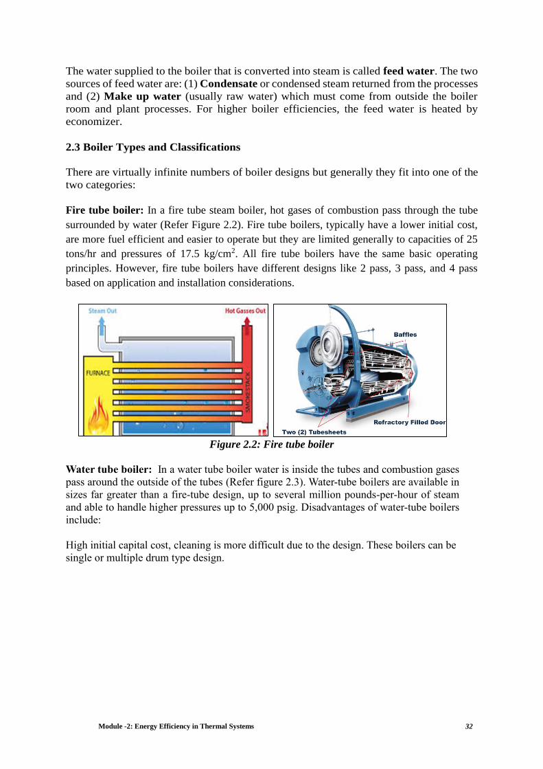
and (2) Make up water (usually raw water) which must come from outside the boiler
room and plant processes. For higher boiler efficiencies, the feed water is heated by
economizer.
2.3 Boiler Types and Classifications
There are virtually infinite numbers of boiler designs but generally they fit into one of the
two categories:
Fire tube boiler: In a fire tube steam boiler, hot gases of combustion pass through the tube
surrounded by water (Refer Figure 2.2). Fire tube boilers, typically have a lower initial cost,
are more fuel efficient and easier to operate but they are limited generally to capacities of 25
tons/hr and pressures of 17.5 kg/cm2. All fire tube boilers have the same basic operating
principles. However, fire tube boilers have different designs like 2 pass, 3 pass, and 4 pass
based on application and installation considerations.
Figure 2.2: Fire tube boiler
Water tube boiler: In a water tube boiler water is inside the tubes and combustion gases
pass around the outside of the tubes (Refer figure 2.3). Water-tube boilers are available in
sizes far greater than a fire-tube design, up to several million pounds-per-hour of steam
and able to handle higher pressures up to 5,000 psig. Disadvantages of water-tube boilers
include:
High initial capital cost, cleaning is more difficult due to the design. These boilers can be
single or multiple drum type design.

Module -2: Energy Efficiency in Thermal Systems 33
Figure 2.3: Water tube boiler
Once Through Boiler:
Feed water from the bottom header, evaporating it in water tubes, and taking out steams
from the top header. In this type of boiler the water flow is only one way.
Traditionally boilers circulate water within them and only a portion gets turned into steam
on any one pass. Circulation ratios (the amount of water recirculated versus the amount
taken out as steam) can vary from 3 to 20.
A once through boiler passes the water through the tubes only once and there is no
circulation ratio. Small once-through boilers will have a mixture of steam and water
coming out boiler which is separated and the water is returned to the front of the boiler.
Large scale power plant type once through boilers will have 100% conversion to steam
before it comes out of the boiler.
Figure 2.4: Basics of once through boiler

Module -2: Energy Efficiency in Thermal Systems 34
Effects of using once through boiler are;
1. High efficiency: Boiler efficiency of 98%
2. Stable steam pressure: ±0.01MPa with static load
3. Long life: Designed to last for 15 years
Packaged Boiler: The packaged boiler is so called because it comes as a complete
package. Once delivered to site it requires only the steam, water pipe work, fuel supply
and electrical connections to be made for it to become operational. Package boilers are
generally of shell type with fire tube design to achieve high heat transfer rates by both
radiation and convection (Refer Figure 2.5).
Figure 2.5: Packaged boiler
The features of package boilers are:
Small combustion space and high heat release rate resulting in faster evaporation.
Large number of small diameter tubes leading to good convective heat transfer.
Forced or induced draft systems resulting in good combustion efficiency.
Number of passes resulting in better overall heat transfer.
Higher thermal efficiency levels compared with other boilers.
Packaged boilers can be both water tube and fire tube boilers. Packaged boilers can only
be used with oil and gas as fuel without separate preparation devices.
Solid Fuel fired boilers
There are different type’s solid fuels available and few common fuels are: Coal, Wood,
Rice husk, Baggasse. There are different type furnaces for these fuels. Most used solid fuel
is coal. Wood, Rice husk is also used as fuel for many boilers as it is easily available in
local area. For rice mill rice husk is a by-product and all boilers in rice mill run by rice
husk.
Furnace for firing solid fuel depends on type of fuel and burning rate of fuel per hour.
Depending on the design of the furnace, boiler is classified:
Stoker Fired Boiler
Stokers are classified according to the method of feeding fuel to the furnace and by the
type of grate. The main classifications are:
Chain-grate or traveling-grate stoker
Spreader stoker

Module -2: Energy Efficiency in Thermal Systems 35
Chain-Grate or Traveling-Grate Stoker Boiler
Coal is fed on to one end of a moving steel grate. As grate moves along the length of the
furnace, the coal burns before dropping off at the end as ash. Some degree of skill is
required, particularly when setting up the grate, air dampers and baffles, to ensure clean
combustion leaving the minimum of unburnt carbon in the ash.
The coal-feed hopper runs along the entire coal-feed end of the furnace. A coal grate is
used to control the rate at which coal is fed in to the furnace by controlling the thickness
of the fuel bed. Coal must be uniform in size as large lumps will not burn out completely
by the time they reach the end of the grate (Refer Figure 2.6).
Figure 2.6: Chain-Grate Stoker
Spreader Stoker Boiler
Spreader stokers utilize a combination of suspension burning and grate burning. The coal
is continually fed into the furnace above a burning bed of coal. The coal fines are burned
in suspension; the larger particles fall to the grate, where they are burned in a thin, fast-
burning coal bed. This method of firing provides good flexibility to meet load fluctuations,
since ignition is almost instantaneous when firing rate is increased. Hence, the spreader
stoker is favored over other types of stokers in many industrial applications.
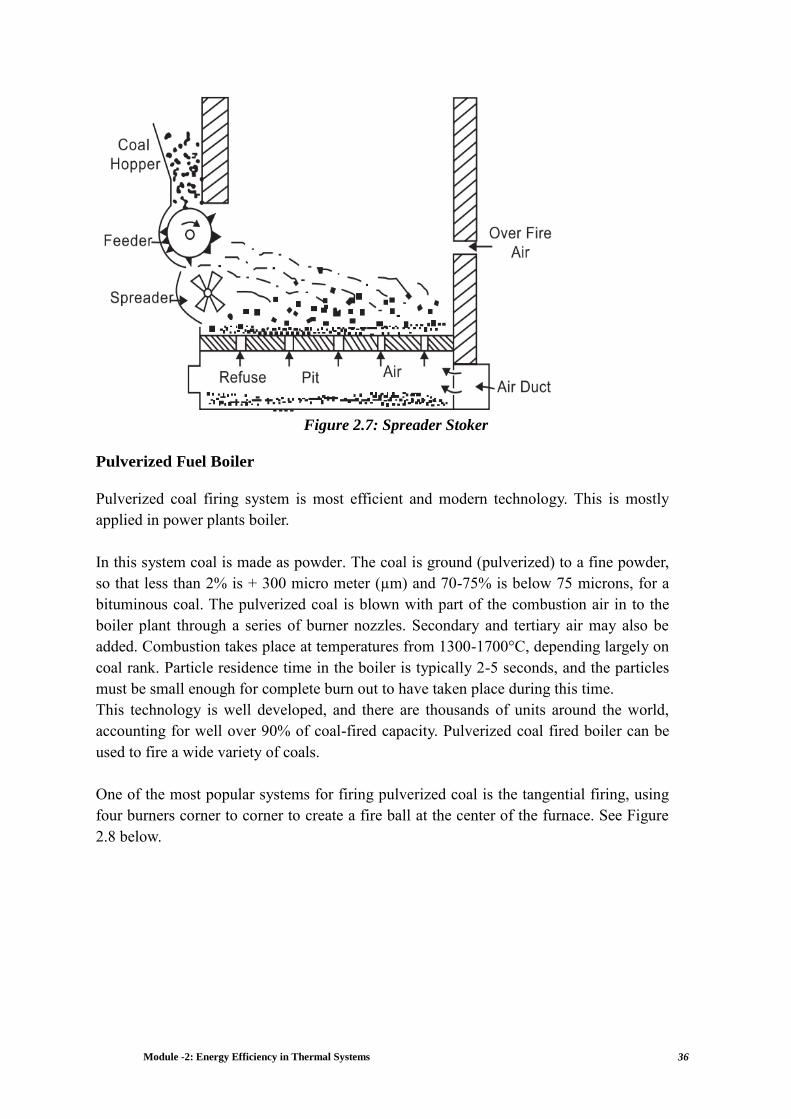
Module -2: Energy Efficiency in Thermal Systems 36
Figure 2.7: Spreader Stoker
Pulverized Fuel Boiler
Pulverized coal firing system is most efficient and modern technology. This is mostly
applied in power plants boiler.
In this system coal is made as powder. The coal is ground (pulverized) to a fine powder,
so that less than 2% is + 300 micro meter (µm) and 70-75% is below 75 microns, for a
bituminous coal. The pulverized coal is blown with part of the combustion air in to the
boiler plant through a series of burner nozzles. Secondary and tertiary air may also be
added. Combustion takes place at temperatures from 1300-1700°C, depending largely on
coal rank. Particle residence time in the boiler is typically 2-5 seconds, and the particles
must be small enough for complete burn out to have taken place during this time.
This technology is well developed, and there are thousands of units around the world,
accounting for well over 90% of coal-fired capacity. Pulverized coal fired boiler can be
used to fire a wide variety of coals.
One of the most popular systems for firing pulverized coal is the tangential firing, using
four burners corner to corner to create a fire ball at the center of the furnace. See Figure
2.8 below.

Module -2: Energy Efficiency in Thermal Systems 37
Figure 2.8: Tangential Firing
FBC Boiler
Fluid is edged combustion has significant advantages over conventional firing systems and
offers multiple benefits namely fuel flexibility, reduced mission of noxious pollutants such
as SOx and NOx, compact boiler design and higher combustion efficiency.
When an evenly distributed air or gas is passed upward through a finely divided bed of
solid particles such as sand supported on a fine mesh, the particles are undisturbed at low
velocity. As air velocity is gradually increased, a stage is reached when the individual
particles are suspended in the air stream. Further, increase in velocity gives rise to bubble
formation, vigorous turbulence and rapid mixing and the bed is said to be fluidized.
Figure 2.9: Schematic of fluidized bed boiler

Module -2: Energy Efficiency in Thermal Systems 38
Super Critical Boiler
In the temperature entropy diagram of steam, a point is reached where the boiling water
and dry saturated steam lines converge and at that point, the latent heat is zero. The critical
point corresponds to a pressure of 221.2 bar absolute and a temperature of 374.18 °C.
If water is heated beyond the above condition, steam parameters are referred to as super
critical. A boiler producing steam above the critical pressure is called the supercritical
boiler. While sub-critical boiler has three distinct sections - economiser, evaporator and
super heater the supercritical boiler has only an economiser and super heater. The
advantages of super critical boilers are
Higher heat transfer rate
More flexible in accepting load variation
Greater ease of operation
High thermal efficiency (40-42% of power generating stations)
The absence of two-phase mixer minimise the problems of erosion and corrosion
Steadier pressure level
The super critical boilers call for special materials to be used for constituent heat transfer
surfaces like drum, water walls, economizer and re-heaters, in order to withstand the
elevated pressure & temperature conditions.
2.4 Performance Evaluation of Boilers
The performance of boiler, like efficiency and evaporation ratio reduces with time due to
poor combustion, heat transfer surface fouling and poor operation and maintenance.
Deteriorating fuel quality, water quality etc. also leads to poor boiler performance.
Efficiency tests help us to find out the deviation of boiler efficiency from the best
efficiency and target problems for corrective action.
Boiler Efficiency
Thermal efficiency of boiler is defined as the percentage of heat input that is effectively
utilized to generate steam. There are two methods of assessing boiler efficiency.
1. The Direct Method: Where the energy gain of the working fluid (water and steam)
is compared with the energy content of the boiler fuel.
2. The Indirect Method: Where the efficiency is the difference between the losses and
the energy input.

Module -2: Energy Efficiency in Thermal Systems 39
a. Direct Method
This is also known as ‘input-output method’ due to the fact that it needs only the useful
output (steam) and the heat input (i.e. fuel) for evaluating the efficiency. This efficiency
can be evaluated using the formula.
100xInputHeat
OutputHeatEfficiencyBoiler
Parameters to be monitored for the calculation of boiler efficiency by direct method are:
Quantity of steam generated per hour (Q) in kg/hr.
Quantity of fuel used per hour (q) in kg/hr.
The working pressure (in kg/cm2(g)) and superheat temperature (oC), if any
The temperature of feed water (oC)
Type of fuel and gross calorific value of the fuel (GCV) in kcal/kg of fuel
100xGCVxq
)hh(xQ)(EfficiencyBoiler
fg
Where, hg - Enthalpy of saturated steam in kcal/kg of steam
hf - Enthalpy of feed water in kcal/kg of water
The fuel calorific value may be gross or net and accordingly, the efficiency reported is
referred to as efficiency on GCV or NCV basis.
Example 2.1
Find out the efficiency of the boiler by direct method with the data given below:
Type of boiler : Coal fired
Quantity of steam (dry) generated : 8 TPH
Steam pressure / temp : 10 kg/cm2(g)/ 180 0C
Quantity of coal consumed : 1.8 TPH
Feed water temperature : 85 0C
GCV of coal : 3200 kCal/kg
Enthalpy of saturated steam at 10 kg/cm2 pressure : 665 kCal/kg(saturated)
Enthalpy of feed water : 85 kCal/kg
Solution:
Boiler Efficiency (η) = 10032008.1
)85665(8
= 80% (on GCV basis)
It should be noted that boiler may not generate 100% saturated dry steam and there may
be some amount of wetness in the steam. Since it is practically difficult to measure the
dryness fraction, it is assumed the boiler generates 100% saturated steam for calculation
purposes. The resulting errors are likely to be in significant.

Module -2: Energy Efficiency in Thermal Systems 40
Advantages:
Plant people can evaluate quickly the efficiency of boilers
Requires few parameters for computation
Needs few instruments for monitoring
Disadvantages:
Does not give clues to the operator as to why efficiency of system is lower
Does not calculate various losses accountable for various efficiency levels
b. Indirect Method
Indirect method also called as heat loss method. The efficiency can be arrived at, by
subtracting the heat loss fractions from 100. All standard does not includes blow down
loss in the efficiency determination process
However, the efficiency calculations are meant for practicing energy managers, simpler
calculation procedure is being adopted in industries.
There are reference standards for Boiler Testing at Site using indirect method namely
British Standard, BS845:1987 and USA Standard is ‘ASME PTC-4.1 Power Test Code
Steam Generating Units’.
The principle losses that occur in a boiler are:
Loss of heat due to dry flue gas
Loss of heat due to moisture in fuel and combustion air
Loss of heat due to combustion of hydrogen
Loss of heat due to radiation
Loss of heat due to un burnt
In the above, loss due to moisture in fuel and the loss due to combustion of hydrogen
cannot be controlled by design and is dependent on the fuel and these two losses are
practically zero while computing the efficiency on the basis of net calorific value.
The data required for calculation of boiler efficiency using indirect method are:
Ultimate analysis of fuel (H2, O2, S, C, moisture content, ash content)
Percentage of Oxygen or CO2 in the flue gas
Flue gas temperature in 0C (Tf)
Ambient temperature in 0C (Ta)
Humidity of air in kg/kg of dry air
GCV of fuel kcal/kg
Percentage combustible in ash (in case of solid fuels)
GCV of ash in kcal/kg (in case of solid fuels)
Solution:
Excess Air supplied (EA) = 100%21
%
2
2 O
O
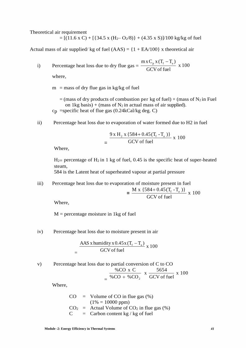
Module -2: Energy Efficiency in Thermal Systems 41
Theoretical air requirement
= [(11.6 x C) + [{34.5 x (H2– O2/8)} + (4.35 x S)]/100 kg/kg of fuel
Actual mass of air supplied/ kg of fuel (AAS) = {1 + EA/100} x theoretical air
i) Percentage heat loss due to dry flue gas = 100xfuelofGCV
)TT(xCxm afp
where,
m = mass of dry flue gas in kg/kg of fuel
= (mass of dry products of combustion per kg of fuel) + (mass of N2 in Fuel
on 1kg basis) + (mass of N2 in actual mass of air supplied).
cp =specific heat of flue gas (0.24kCal/kg deg. C)
ii) Percentage heat loss due to evaporation of water formed due to H2 in fuel
= 100x
fuel of GCV
)} T-(T 0.45 {584 x H x 9 af2
Where,
H2= percentage of H2 in 1 kg of fuel, 0.45 is the specific heat of super-heated
steam,
584 is the Latent heat of superheated vapour at partial pressure
iii) Percentage heat loss due to evaporation of moisture present in fuel
= 100xfuel of GCV
)} T-(T 0.45 {584 xM af
Where,
M = percentage moisture in 1kg of fuel
iv) Percentage heat loss due to moisture present in air
=
100xfuelofGCV
)TT(x45.0xhumidityxAAS af
v) Percentage heat loss due to partial conversion of C to CO
=
100xfuelofGCV
5654x
CO%CO%
CxCO%
2
Where,
CO = Volume of CO in flue gas (%)
(1% = 10000 ppm)
CO2 = Actual Volume of CO2 in flue gas (%)
C = Carbon content kg / kg of fuel

Module -2: Energy Efficiency in Thermal Systems 42
vi) Percentage heat loss due to un burnt in fly ash
= Total ash collected per kg of fuel burnt x G.C.V of fly ash x100
GCV of fuel
vii) Percentage heat loss due to un burnt in bottom ash
= Total ash collected per kg of fuel burnt x G.C.V of bottom ash x100
GCV of fuel
viii) Percentage heat loss due to radiation and other un accounted loss
The actual radiation and convection losses are difficult to assess because of particular
emissivity of various surfaces, its inclination, airflow pattern etc. In a relatively small
boiler, with a capacity of 10MW, the radiation and unaccounted losses could amount to
between 1% and 2% of the gross calorific value of the fuel, while in a 500MW boiler,
values between 0.2% to1% are typical. The loss may be assumed appropriately depending
on the surface condition.
Example 2.2 Calculating boiler efficiency by indirect method
Type of boiler : Oil fired
Ultimate analysis of Oil:
C - 84.0%; H2 -12.0%; S- 3.0%; O2 -1.0%; GCV of Oil- 10200kCal/kg
Percentage of Oxygen in flue gas :7
Percentage of CO2in flue gas :11
Flue gas temperature(Tf) : 2200C
Ambient temperature(Ta) : 27 0C
Humidity of air : 0.018 kg/kg of dry air
Radiation and other unaccounted losses : 3.5% (estimated)
Solution
1. Excess air supplied(EA) = (7 x100)/(21-7) =50%
2. Theoretical air requirement
= [(11.6 x C) + {34.5 x (H2 – O2/8)} + (4.35 x S)]/100 kg/kg of fuel
= [(11.6 x 84) + {34.5 x (12 – 1/8)} + (4.35 x 3)]/100 kg/kg of fuel
= 974.4 + 409.6875+13.05
= 13.97

Module -2: Energy Efficiency in Thermal Systems 43
3. Actual mass of air supplied per kg of fuel
= [1+EA/100] x Theo .Air (AAS)
= [1 + 50/100] x13.97
= 20.96
4. Percentage heat loss due to dry flue gas (L1) = 100xfuelofGCV
)TT(xCxm afp
m = (0.84 x (44/12)) + (0.03 x (64/32)) + (20.96 x 0.77) + ((20.96 – 13.97) x 0.23)
= 3.08 + 0.06 + 16.14 + 1.61 = 20.89
L1 = 20.89 x 0.24 x (220 – 27) x 100 / 10200 = 9.49%
5. Percentage heat loss due to evaporation of water formed due to H2 in fuel (L2)
= 100x
fuel of GCV
)} T-(T 0.45 {584 x H x 9 af2
L2 = 9 x 12 {584 + 0.45 (220-27)} x 100 /10200 = 7.10%
6. Percentage heat loss due to moisture present in air (L3)
=
100xfuelofGCV
)TT(x45.0xhumidityxAAS af
L3 = 20.96 x 0.018 x 0.45 (220-27) x 100 / 10200 = 0.31%
7. Percentage heat loss due to radiation and other unaccounted losses (L4) = 3.5%
(given)
Boiler Efficiency = 100 – (L1 + L2 + L3 + L4)
= 100 – (9.49 + 7.1 + 0.31 + 3.5) = 79.6%
Boiler Evaporation Ratio
Evaporation ratio means kilogram of steam generated per kilogram of fuel consumed.
Evaporation ratio monitoring is best suited for any boiler when its own performance is
compared on day to day basis as a performance indicator; given that enthalpy gain in steam
and fuel calorific value remain constant. A drop in evaporation ratio indicates a drop in
Boiler efficiency.
Typical values of Evaporation ratio for different type of fuels are as follows:
Biomass fired boilers : 2.0 to 3.0
Coal fired boilers : 4.0 to 5.5
Oil fired boilers : 13.5 to 14.5
Gas fired boilers : 11.0 to 13.0
However, the above ratio will depend upon the type of boiler and associated efficiencies.

Module -2: Energy Efficiency in Thermal Systems 44
2.5 Boiler Blow down
The impurities found in boiler water depend on the untreated feed water quality, the
treatment process used and the boiler operating procedures. As a general rule, the higher
is the boiler operating pressure, the greater will be the sensitivity to impurities. As the feed
water materials evaporate in to steam, dissolved solids concentrate in the boiler either in a
dissolved or suspended state. Above a certain level of concentration, these solids
encourage foaming and cause carryover of water in to the steam. This leads to scale
formation inside the boiler, resulting in localized overheating and ending finally in tube
failure.
It is therefore necessary to control the level of concentration of the solid sand this is
achieved by the process of' blowing down', where a certain volume of water is blown off
and is automatically replaced by feed water - thus maintaining the optimum level of total
dissolved solids (TDS) in the water. Blow down is necessary to protect the surfaces of the
heat exchanger in the boiler. However, blow down can be a significant source of heat loss,
if improperly carried out. The maximum amount of total dissolved solids (TDS)
concentration permissible in various types of boilers is given inTable2.1.
Table 2.1: Recommended TDS levels for various boilers
Boiler Type Maximum TDS (ppm)
1. Smoke and water tube boilers (12 kg/cm2) 5,000 ppm
2. Low pressure Water tube boiler 2000-3000
3. High Pressure Water tube boiler with super heater
etc.
3,000 - 3,500 ppm
4. Package and economic boilers 3,000 ppm
5. Coil boilers and steam generators 2000 (in the feed water)
Conductivity as Indicator of Boiler Water Quality
Conductivity is a standard measurement for monitoring the overall total dissolved solids
present in the boiler. Arise in conductivity indicates arise in the" contamination" of the
boiler water.
Intermittent vs. Continuous Blow down
Conventional methods for blowing down the boiler depend on two kinds of blow down –
intermittent and continuous.
Intermittent Blow down
The parameters that are most often monitored to ensure the quality of steam are TDS or
conductivity, pH, Silica and Phosphates concentration. The boiler is blown down by
manually operating a valve fitted to discharge pipe at the lowest point of boiler shell to
reduce these levels and keeping them controlled to a point where the steam quality is not
likely to be affected. A substantial amount of heat energy is lost in this process. In
intermittent blow down, a large diameter line is opened for a short period of time, the time
being based on a thumb rule such as “once a shift for 2 minutes”.

Module -2: Energy Efficiency in Thermal Systems 45
Continuous Blow down
There is a steady and constant dispatch of small stream of concentrated boiler water. In a
continuous blow down, large quantities of heat are wasted though it is inevitable especially
in large high pressure boilers. However, opportunity exists for recovering this heat by
blowing in to a flash tank and generating flash steam. This flash steam can be used for pre-
heating boiler feed water or for any other purpose.
Figure 2.8: Blow down heat recovery system
Benefits of Blow down
Good boiler blow down control can significantly reduce treatment and operation al costs
that include:
− Lower pre-treatment costs
− Less make-up water consumption
− Reduced maintenance own time
− Increased boiler life
− Lower consumption of treatment chemicals
The following formula gives the quantity of blow down required:
Blow down (%) =TDS) waterFeed- waterBoiler in TDS ePermissibl (Maximum
water]up Make % x TDS water[Feed

Module -2: Energy Efficiency in Thermal Systems 46
If maximum permissible limit of TDS as in a package boiler is 3000ppm, percentage make
up water is 10% and TDS in feed water is 300ppm, then the percentage blow down is given
as:
= (300 x 10) / (3000 – 300)
= 1.11%
If boiler evaporation rate is 3000 kg/hr, then required blow down rate is:
= 3000 x 0.0111
= 33.3kg/hr
2.6 Boiler Water Treatment
Producing quality steam on demand depend son properly managed water treatment to
control steam purity, deposits and corrosion. A boiler is the sump of the boiler system. It
ultimately receives all of the pre-boiler contaminants. Boiler performance, efficiency, and
service life are direct products of selecting and controlling feed water used in the boiler.
The boiler water must be sufficiently free of deposit forming solids to allow rapid and
efficient heat transfer and it must not be corrosive to the boiler metal. Deposits and
corrosion result in efficiency losses and may cause boiler tube failures and inability to
produce steam.
Deposit Control
Deposits in boilers may result from hardness contamination of feed water and corrosion
products from the condensate and feed water system. Hardness contamination of the feed
water may arise due to deficient softener system. Deposits and corrosion result in
efficiency losses and may result in boiler tube failures and inability to produce steam.
Deposits act as insulators and slow heat transfer. Large amounts of deposits throughout
the boiler could reduce the heat transfer enough to reduce the boiler efficiency
significantly. Different type of deposits affects the boiler efficiency differently. Thus it
may be useful to analyse the deposits for its characteristics. The insulating effect of
deposits causes the boiler metal temperature to rise and may lead to tube-failure by
overheating.
Impurities causing deposits
The most important chemicals contained in water that influences the formation of deposits
in the boilers are the salts of calcium and magnesium, which are known as hardness salts.
Calcium and magnesium bicarbonate dissolve in water to form an alkaline solution and
these salts are known as alkaline hardness. They decompose upon heating, releasing
carbon dioxide and forming a soft sludge, which settles out. These are called temporary
hardness-hardness that can be removed by boiling.
Calcium and magnesium sulphates, chlorides and nitrates, etc. when dissolved in water are
chemically neutral and are known as non-alkaline hardness. These are called permanent
hardness and form hard scales on boiler surfaces, which are difficult to remove. Non-
alkalinity hardness chemicals fall out the solution due to reduction in solubility as the

Module -2: Energy Efficiency in Thermal Systems 47
temperature rises, by concentration due to evaporation which takes place within the boiler,
or by chemical change to a less soluble compound.
Silica
The presence of silica in boiler water can rise to formation of hard silicate scales. It can
also associate with calcium and magnesium salts, forming calcium and magnesium
silicates of very low thermal conductivity. Silica can give rise to deposits on steam turbine
blades, after been carried over either in droplets of water in steam, or in volatile form in
steam at higher pressures.
Two major types of boiler water treatment are: Internal water treatment and External water
treatment,
Two major types of boiler water treatment are: Internal water treatment and External water
treatment.
Internal Water Treatment
Internal treatment is carried out by adding chemicals to boiler to prevent the formation of
scale by converting the scale-forming compounds to free-flowing sludge’s, which can be
removed by blow down. This method is limited to boilers, where feed water is low in
hardness salts, to low pressures high TDS content in boiler water is tolerated, and when
only small quantity of water is required to be treated. If these conditions are not applied,
then high rates of blow down are required to dispose the sludge. They become
uneconomical from heat and water loss consideration.
Different waters require different chemicals. Sodium carbonate, sodium aluminate, sodium
phosphate, sodium sulphite and compounds of vegetable or inorganic origin are all used
for this purpose. Proprietary chemicals are available to suit various water conditions. The
specialist must be consulted to determine the most suitable chemicals to use in each case.
Internal treatment alone is not recommended.
External Water Treatment
External treatment is used to remove suspended solids, dissolved solids (particularly the
calcium and magnesium ions which are major causes of scale formation) and dissolved
gases (oxygen and carbon dioxide).
The external treatment processes available are: ion exchange; demineralization; reverse
osmosis and de-aeration. Before any of these are used, it is necessary to remove suspended
solids and colour from the raw water, because these may foul the resins used in the
subsequent treatment sections.
Methods of pre-treatment include simple sedimentation in settling tanks or settling in
clarifiers with aid of coagulants and flocculants. Pressure sand filters, with spray aeration
to remove carbon dioxide and iron, may be used to remove metal salts from bore well
water.
The first stage of treatment is to remove hardness salt and possibly non-hardness salts.
Removal of only hardness salts is called softening, while total removal of salts from
solution is called demineralization.

Module -2: Energy Efficiency in Thermal Systems 48
The processes are:
Ion-exchange process (Softener Plant)
In ion-exchange process, the hardness is
removed as the water passes through bed of
natural zeolite or synthetic resin and without
the formation of any precipitate. The simplest
type is ‘base exchange’ in which calcium and
magnesium ions are exchanged for sodium
ions. After saturation regeneration is done with
sodium chloride. The sodium salts being soluble, do not form scales in boilers. Since base
exchanger only replaces the calcium and magnesium with sodium, it does not reduce the
TDS content, and blow down quantity. It also does not reduce the alkalinity.
Demineralization is the complete removal of all salts. This is achieved by using a “caution”
resin, which exchanges the cations in the raw water with hydrogen ions, producing
hydrochloric, sulphuric and carbonic acid. Carbonic acid is removed in degassing tower in
which air is blown through the acid water. Following this, the water passes through an
“anion” resin which exchanges anions with the mineral acid (e.g. sulphuric acid) and forms
water. Regeneration of cations and anions is necessary at intervals using, typically, mineral
acid and caustic soda respectively. The complete removal of silica can be achieved by
correct choice of anion resin.
Ion exchange processes can be used for almost total demineralization if required, as is the
case in large electric power plant boilers
De-aeration
In de-aeration (Figure 2.9), dissolved gases, such as oxygen and carbon dioxide, are
expelled by preheating the feed water before it enters the boiler.
All natural waters contain dissolved gases in solution. Certain gases, such as carbon
dioxide and oxygen, greatly increase corrosion. When heated in boiler systems, carbon
dioxide (CO2) and oxygen (O2) are released as gases and combine with water (H2O) to
form carbonic acid, (H2CO3).
Figure 2.9: Deaerator
Softening reaction
Na2R + Ca(HCO3)2 « CaR + 2 Na(HCO3)
Regeneration reaction
CaR + 2 NaCl « Na2R + CaCl2

Module -2: Energy Efficiency in Thermal Systems 49
Removal of oxygen, carbon dioxide and other non-condensable gases from boiler feed
water is vital to boiler equipment longevity as well as safety of operation. Carbonic acid
corrodes metal reducing the life of equipment and piping. It also dissolves iron (Fe) which
when returned to the boiler precipitates and causes scaling on the boiler and tubes. This
scale not only contributes to reducing the life of the equipment but also increases the
amount of energy needed to achieve heat transfer.
De-aeration can be done by mechanical de-aeration, by chemical de-aeration or by both
together.
Mechanical de-aeration
Mechanical de-aeration for the removal of these dissolved gases is typically utilized prior
to the addition of chemical oxygen scavengers. Mechanical de-aeration is based on
Charles' and Henry's laws of physics. Simplified, these laws state that removal of oxygen
and carbon dioxide can be accomplished by heating the boiler feed water, which reduces
the concentration of oxygen and carbon dioxide in the atmosphere surrounding the feed
water. Mechanical de-aeration can be the most economical. They operate at the boiling
point of water at the pressure in the de-aerator. They can be of vacuum or pressure type.
The vacuum type of de-aerator operates below atmospheric pressure, at about 82o
C, can
reduce the oxygen content in water to less than 0.02 mg/litre. Vacuum pumps or steam
ejectors are required to maintain the vacuum.
The pressure-type de-aerators operates by allowing steam into the feed water through a
pressure control valve to maintain the desired operating pressure, and hence temperature
at a minimum of 105oC. The steam raises the water temperature causing the release of O2
and CO2 gases that are then vented from the system. This type can reduce the oxygen
content to 0.005 mg/litre.
Where excess low-pressure steam is available, the operating pressure can be selected to
make use of this steam and hence improve fuel economy. In boiler systems, steam is
preferred for de-aeration because:
− Steam is essentially free from O2 and CO2
− Steam is readily available
− Steam adds the heat required to complete the reaction.
Chemical de-aeration
While the most efficient mechanical deaerators reduce oxygen to very low levels (0.005
mg/litre), even trace amounts of oxygen may cause corrosion damage to a system.
Consequently, good operating practice requires removal of that trace oxygen with a
chemical oxygen scavenger such as sodium sulfite or hydrazine. Sodium sulphite reacts
with oxygen to form sodium sulphate, which increases the TDS in the boiler water and
hence increases the blow down requirements and make-up water quality. Hydrazine reacts
with oxygen to form nitrogen and water. It is invariably used in high pressures boilers
when low boiler water solids are necessary, as it does not increase the TDS of the boiler
water.

Module -2: Energy Efficiency in Thermal Systems 50
Reverse Osmosis
When solutions of differing concentrations are separated by a semi-permeable membrane,
water from less concentrated solution passes through the membrane to dilute the liquid of
high concentration, which is called osmosis. If the solution of high concentration is
pressurized, the process is reversed and the water from the solution of high concentration
flows to the weaker solution. This is known as reverse osmosis.
The semi permeable
nature of the membrane
allows the water to pass
much more readily than
the dissolved minerals.
Since the water in the
less concentrated
solution seeks to dilute
the more concentrated
solution, the water
passage through the
membrane generates a
noticeable head
difference between the
two solutions. This head
difference is a measure
of the concentration
difference of the two
solutions and is referred
to as the osmotic
pressure difference.
When a pressure is
applied to the
concentrated solution
which is great that the
osmotic pressure
difference, the direction
of water passage
through the membrane
is reversed and the
process that we refer to
as reverse osmosis is

Module -2: Energy Efficiency in Thermal Systems 51
established. That is, the
membrane's ability to
selectively pass water is
unchanged, only the
direction of the water
flow is changed.
The feed water and
concentrate (reject
stream) ports illustrates
a continuously
operating RO system.
Figure 2.10: Reverse Osmosis
The quality of water produced depends upon the concentration of the solution on the high-
pressure side and pressure differential across the membrane. This process is suitable for
waters with very high TDS, such as sea water.
Recommended boiler and feed water quality
The impurities found in boiler water depend on the untreated feed water quality, the
treatment process used and the boiler operating procedures. As a general rule, the higher
the boiler operating pressure, the greater will be the sensitivity to impurities.
Recommended feed water and boiler water limits are shown in Table 2.2 and Table 2.3.
Table 2.2: Recommended feed water limits
Factor Up to 20Kg/cm2 21 - 40Kg/cm2 41 - 60Kg/cm2 Total iron (max)ppm 0.05 0.02 0.01
Total copper (max)ppm 0.01 0.01 0.01
Total silica (max)ppm 1.0 0.3 0.1
Oxygen (max)ppm 0.02 0.02 0.01
Hydrazine residualppm - - -0.02-0.04
0 pH at 25C 8.8-9.2 8.8-9.2 8.2-9.2
Hardness 1.0 0.5 -
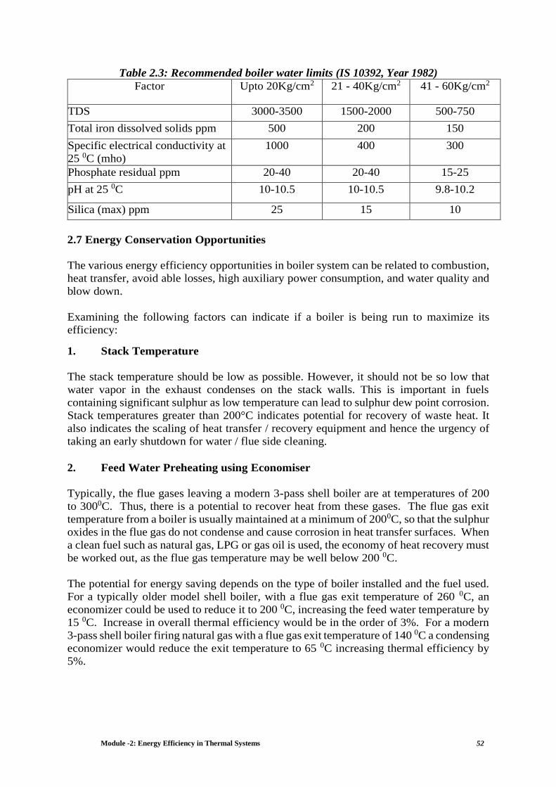
Module -2: Energy Efficiency in Thermal Systems 52
Table 2.3: Recommended boiler water limits (IS 10392, Year 1982)
Factor Upto 20Kg/cm2 21 - 40Kg/cm2 41 - 60Kg/cm2
TDS 3000-3500 1500-2000 500-750
Total iron dissolved solids ppm 500 200 150
Specific electrical conductivity at
25 0C (mho)
1000 400 300
Phosphate residual ppm 20-40 20-40 15-25
pH at 25 0C 10-10.5 10-10.5 9.8-10.2
Silica (max) ppm 25 15 10
2.7 Energy Conservation Opportunities
The various energy efficiency opportunities in boiler system can be related to combustion,
heat transfer, avoid able losses, high auxiliary power consumption, and water quality and
blow down.
Examining the following factors can indicate if a boiler is being run to maximize its
efficiency:
1. Stack Temperature
The stack temperature should be low as possible. However, it should not be so low that
water vapor in the exhaust condenses on the stack walls. This is important in fuels
containing significant sulphur as low temperature can lead to sulphur dew point corrosion.
Stack temperatures greater than 200°C indicates potential for recovery of waste heat. It
also indicates the scaling of heat transfer / recovery equipment and hence the urgency of
taking an early shutdown for water / flue side cleaning.
2. Feed Water Preheating using Economiser
Typically, the flue gases leaving a modern 3-pass shell boiler are at temperatures of 200
to 3000C. Thus, there is a potential to recover heat from these gases. The flue gas exit
temperature from a boiler is usually maintained at a minimum of 2000C, so that the sulphur
oxides in the flue gas do not condense and cause corrosion in heat transfer surfaces. When
a clean fuel such as natural gas, LPG or gas oil is used, the economy of heat recovery must
be worked out, as the flue gas temperature may be well below 200 0C.
The potential for energy saving depends on the type of boiler installed and the fuel used.
For a typically older model shell boiler, with a flue gas exit temperature of 260 0C, an
economizer could be used to reduce it to 200 0C, increasing the feed water temperature by
15 0C. Increase in overall thermal efficiency would be in the order of 3%. For a modern
3-pass shell boiler firing natural gas with a flue gas exit temperature of 140 0C a condensing
economizer would reduce the exit temperature to 65 0C increasing thermal efficiency by
5%.

Module -2: Energy Efficiency in Thermal Systems 53
3. Combustion Air Pre heat
Combustion air preheating is an alternative to feed water heating. In order to improve
thermal efficiency by 1%, the combustion air temperature must be raised by 200C. Most
gas and oil burners used in a boiler plant are not designed for high air preheat temperatures.
Modern burners can withstand much higher combustion air preheat, so it is possible to
consider such units as heat exchangers in the exit flue as an alternative to an economizer,
when either space or a high feed water return temperature make it viable.
4. Incomplete Combustion
Incomplete combustion can arise from a shortage of air or surplus of fuel or poor
distribution of fuel. It is usually obvious from the colour or smoke, and must be corrected
immediately.
In the case of oil and gas fired systems, CO or smoke (for oil fired systems only) with
normal or high excess air indicates burner system problems. A more frequent cause of
incomplete combustion is the poor mixing of fuel and air at the burner. Poor oil fires can
result from improper viscosity, worn tips, carbonization on tips and deterioration of
diffusers or spinner plates.
With coal firing, unburned carbon can comprise a big loss. It occurs as grit carry-over or
carbon-in-as hand may amount to more than 2% of the heat supplied to the boiler. Non
uniform fuel size could be one of the reasons for incomplete combustion. In chain grate
stokers, large lumps will not burnout completely, while small pieces and fines may block
the air passage, thus causing poor air distribution. In sprinkler stokers, stoker grate
condition, fuel distributors, wind box air regulation and over-fire systems can affect carbon
loss. Increase in the fines in pulverized coal also increases carbon loss.
5. Excess Air Control
Excess air is required in all practical cases to ensure complete combustion, to allow for the
normal variations in combustion and to ensure satisfactory stack conditions for some fuels.
The optimum excess air level for maximum boiler efficiency occurs when the sum of the
losses due to in complete combustion and loss due to heat in flue gases is minimum. This
level varies with furnace design, type of burner, fuel and process variables. It can be
determined by conducting tests with different air fuel ratios.
The Table2.4 gives the theoretical amount of air required for combustion of various types
of fuel.

Module -2: Energy Efficiency in Thermal Systems 54
Table 2.4: Theoretical combustion data – common boiler fuels
Fuel
kg of air
req./kg of
fuel
kg of flue
gas/kg of
fuel
m3 of
flue/kg of
fuel
Theoretical
CO2% in dry
flue gas
CO2% in flue
gas achieved
in practice
Solid Fuels
Bagasse
Coal (bituminous)
Lignite
Paddy Husk
Wood
3.2
10.8
8.4
4.6
5.8
3.43
11.7
9.10
5.63
6.4
2.61
9.40
6.97
4.58
4.79
20.65
18.70
19.40
19.8
20.3
10-12
10-13
9 -13
14-15
11.13
Liquid Fuels
Furnace Oil
LSHS
13.90
14.04
14.30
14.63
11.50
10.79
15.0
15.5
9-14
9-14
Typical values of excess air supplied for various fuels are given in Table2. . 5.
Table 2.5: Excess air supplied for various fuels
Fuel Type of Furnace or Burners Excess Air (% by wt.)
Pulverised coal Completely water-cooled furnace for slag-
tap or dry-ash removal
15-20
Partially water-cooled furnace for dry-ash
removal
15-40
Coal Spreader stoker 30-60
Water-cooler vibrating-grate stokers 30-60
Chain-grate and traveling-grate stokers 15-50
Underfeed stoker 20-50
Fuel oil Oil burners, register type 15-20
Multi-fuel burners and flat-flame 20-30
Natural gas High pressure burner 5-7
Wood Dutch over (10-23% through grates) and
Hoff t type
20-25
Bagasse All furnaces 25-35
Black liquor Recovery furnaces for draft and soda-
pulping processes
30-40
Controlling excess air to an optimum level always results in reduction in flue gas losses;
forevery1% reduction in excess air there is approximately 0.6% rise inefficiency.
Various methods are available to control the excess air:
Portable oxygen analysers and draft gauges can be used to make periodic readings
to guide the operator to manually adjust the flow of air for optimum operation.
Excess air reduction up to 20% is feasible.
The most common method is the continuous oxygen analyzer with a local read out
mounted draft gauge, by which the operator can adjust air flow. A further reduction
of 10-15% can be achieved over the previous system.
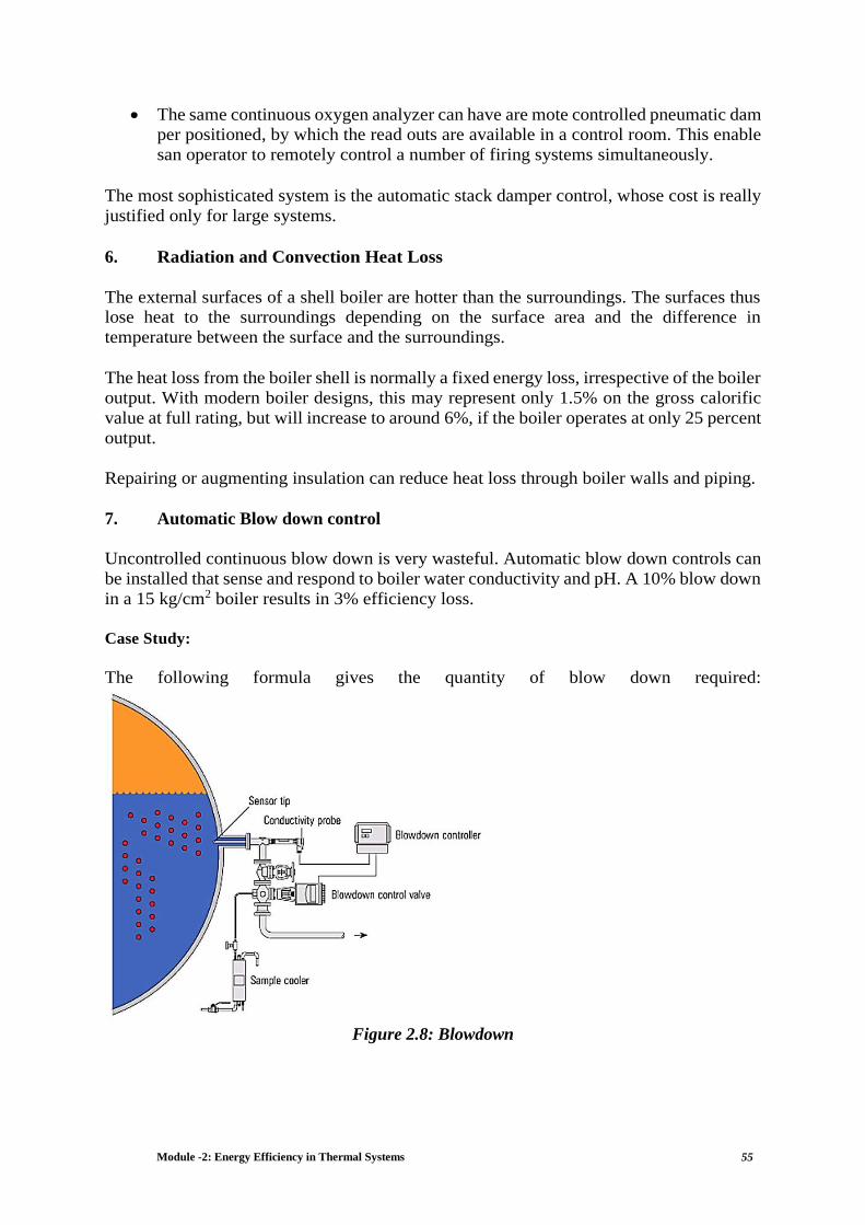
Module -2: Energy Efficiency in Thermal Systems 55
The same continuous oxygen analyzer can have are mote controlled pneumatic dam
per positioned, by which the read outs are available in a control room. This enable
san operator to remotely control a number of firing systems simultaneously.
The most sophisticated system is the automatic stack damper control, whose cost is really
justified only for large systems.
6. Radiation and Convection Heat Loss
The external surfaces of a shell boiler are hotter than the surroundings. The surfaces thus
lose heat to the surroundings depending on the surface area and the difference in
temperature between the surface and the surroundings.
The heat loss from the boiler shell is normally a fixed energy loss, irrespective of the boiler
output. With modern boiler designs, this may represent only 1.5% on the gross calorific
value at full rating, but will increase to around 6%, if the boiler operates at only 25 percent
output.
Repairing or augmenting insulation can reduce heat loss through boiler walls and piping.
7. Automatic Blow down control
Uncontrolled continuous blow down is very wasteful. Automatic blow down controls can
be installed that sense and respond to boiler water conductivity and pH. A 10% blow down
in a 15 kg/cm2 boiler results in 3% efficiency loss.
Case Study:
The following formula gives the quantity of blow down required:
Figure 2.8: Blowdown

Module -2: Energy Efficiency in Thermal Systems 56
10.5 Lakh BDT /Year saving is possible. If we invest 20 Lakh tk then Payback period will
be 1.9 Year.

Module -2: Energy Efficiency in Thermal Systems 57
8. Reduction of Scaling and Soot losses
In oil and coal-fired boilers, soot build upon tubes acts as an insulator against heat transfer.
Any such deposits should be removed on a regular basis. Elevated stack temperatures may
indicate excessive soot build-up. Also same result will occur due to scaling on the
waterside.
High exit gas temperatures at normal excess air indicate poor heat transfer performance.
This condition can result from a gradual build-up of gas-side or waterside deposits. Water
side deposits require are view of water treatment procedures and tube cleaning to remove
deposits. An estimated 1% efficiency loss occurs with every 4.4 0C increase ion stack
temperature.
Stack temperature should be checked and recorded regularly as an indicator of soot
deposits. When the flue gas temperature raises about 200C above the temperature for a
newly cleaned boiler, it is time to remove the soot deposits. It is, therefore, recommended
to install a dial type thermometer at the base of the stack to monitor the exhaust flue gas
temperature.
Every millimetre thickness of soot coating increases the stack temperature by about 550C.
It is also estimated that 3mm of soot can cause an increase in fuel consumption by 2.5%.
Periodic off-line cleaning of radiant furnace surfaces, boiler tube banks, economizers and
air heaters may be necessary to remove stubborn deposits.
9. Reduction of Boiler Steam Pressure
This is an effective means of reducing fuel consumption, if permissible, by as much as 1
to 2%. Lower steam pressure gives a lowers saturated steam temperature and without stack
heat recovery, a similar reduction in the temperature of the flue gas temperature results.
Steam is generated at pressures normally dictated by the highest pressure /temperature
requirements for a particular process. In some cases, the process does not operate all the
time, and there are periods when the boiler pressure could be reduced. The energy manager
should consider pressure reduction carefully, before recommending it. Adverse effects,
such as an increase in water carry over from the boiler owing to pressure reduction, may
negate any potential saving. Pressure should be reduced in stages, and no more than a 20
percent reduction should be considered.
10. Variable Speed Control for Fans, Blowers and Pumps
Variable speed control is an important means of achieving energy savings. Generally,
combustion air control is effected by throttling dampers fitted at forced and induced draft
fans. Though dampers are simple means of control, they lack accuracy, giving poor control
characteristics at the top and bottom of the operating range. In general, if the load
characteristic of the boiler is variable, the possibility of replacing the dampers by a VSD
should be evaluated.

Module -2: Energy Efficiency in Thermal Systems 58
11. Effect of Boiler Loading on Efficiency
The maximum efficiency of the boiler does not occur at full load, but at about two-thirds
of the full load. If the load on the boiler decreases further, efficiency also tends to decrease.
At zero output, the efficiency of the boiler is zero, and any fuel fired is used only to supply
the losses. The factors affecting boiler efficiency are:
As the load falls, so does the value of the mass flow rate of the flue gases through
the tubes. This reduction in flow rate for the same heat transfer area reduced the
exit flue gas temperatures by a small extent, reducing the sensible heat loss.
Below half load, most combustion appliances need more excess air to burn the fuel
completely. This increases the sensible heat loss.
The net effect of these factors is to produce a load / efficiency curve. It has been generally
noticed that the fall in efficiency begins to become serious below about a quarter load, and
as far as possible, operation of boilers below this level should be avoided.
12. Proper Boiler Scheduling
Since the optimum efficiency of boilers occurs at 65-85% of full load, it is usually more
efficient, on the whole, to operate a fewer number of boilers at higher loads, than to operate
a large number at low loads.
13. Boiler Replacement
The potential savings from replacing a boiler depend on the anticipated change in overall
efficiency. A change in a boiler can be financially attractive if the existing boiler is:
old and inefficient
not capable of firing cheaper substitution fuel
over or under-sized for present requirements not
designed for ideal loading conditions
The feasibility study should examine all implications of long-term fuel availability and
company growth plans. All financial and engineering factors should be considered. Since
boiler plants traditionally have a useful life of well over 25 years, replacement must be
carefully studied.
2.8 Case Study
Installing Boiler Economiser
A paper mill retrofitted an economizer to existing boiler. The general specification of the
boiler is given below:
Boiler capacity
(T/h)
Feed water Temp. (0C) Steam pressure (bar) Fuel oil
8 110 18 No.6

Module -2: Energy Efficiency in Thermal Systems 59
The thermal efficiency of the boiler was measured and calculated by the indirect method
using flue gas analyzer and data logger. The result is summarized below:
Thermal efficiency : 80.99%
Flue gas temperature : 3150C
CO2 % : 13
CO (PPM) : 167
The temperature in the flue gas is in the range of 315 to 3200C. The waste heat in the flue
gas is recovered by installing an economizer, which transfers waste heat from the flue
gases to the boiler feed water. This resulted in a rise in feed water temperature by about
260C.
Basic Data
Average quantity of steam generated : 5.04T/h
Average flue gas temperature : 3150C
Average steam generation / kg of fuel oil : 16.05kg
Feed water in let temperature : 1100C
Fuel oil supply rate : 314kg/h
Flue gas quantity : 17.4 kg/kg of fuel
Cost Economics
Quantity of flue gases : 5463.6kg/h
Quantity of heat available in the flue gases : 5463.6 x0.25 x(315-200)
=157078kCal/h
Rise in the feed water temperature : 260C
Heat required for pre-heating the feed water : 5040X1.065X26
=139557kCal/h
Saving in terms of HSD fuel : 139557 kCal/h /10000 kCal/kg
= 14kg/h
Annual operating hours : 8600
Annual savings of fuel oil : 120400kg
Conclusion
Through recovery of waste heat by installation of an economizer, the paper mill was able
to save14kg/hr of HSD fuel, which amounts to about 1, 20,400 kg of fuel oil per annum.
Example 2.1
The efficiency of a boiler on GCV basis is 85%. The fuel contains 1.0 % moisture and 12
% hydrogen. The GCV of fuel is 10,500 Kcal/kg. What is the boiler efficiency on the basis
of net calorific value?
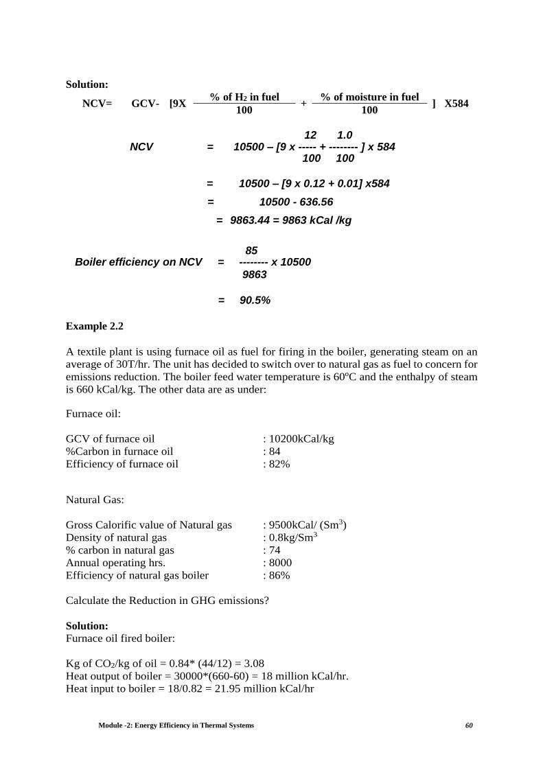
Module -2: Energy Efficiency in Thermal Systems 60
Solution:
NCV= GCV- [9X % of H2 in fuel
+ % of moisture in fuel
] X584 100 100
12 1.0 NCV = 10500 – [9 x ----- + -------- ] x 584
100 100
= 10500 – [9 x 0.12 + 0.01] x584
= 10500 - 636.56
= 9863.44 = 9863 kCal /kg
85 Boiler efficiency on NCV = -------- x 10500 9863
= 90.5%
Example 2.2
A textile plant is using furnace oil as fuel for firing in the boiler, generating steam on an
average of 30T/hr. The unit has decided to switch over to natural gas as fuel to concern for
emissions reduction. The boiler feed water temperature is 60oC and the enthalpy of steam
is 660 kCal/kg. The other data are as under:
Furnace oil:
GCV of furnace oil : 10200kCal/kg
%Carbon in furnace oil : 84
Efficiency of furnace oil : 82%
Natural Gas:
Gross Calorific value of Natural gas : 9500kCal/ (Sm3)
Density of natural gas : 0.8kg/Sm3
% carbon in natural gas : 74
Annual operating hrs. : 8000
Efficiency of natural gas boiler : 86%
Calculate the Reduction in GHG emissions?
Solution:
Furnace oil fired boiler:
Kg of CO2/kg of oil = 0.84* (44/12) = 3.08
Heat output of boiler = 30000*(660-60) = 18 million kCal/hr.
Heat input to boiler = 18/0.82 = 21.95 million kCal/hr

Module -2: Energy Efficiency in Thermal Systems 61
Furnace oil consumption = 21.95*106/ 10200 = 2.152T/hr.
CO2 emission with furnace oil = 2,152* 3.08 = 6.628T/hr.
Gas fired Boiler:
Kg of CO2/kg of gas = 0.74* (44/12) = 2.71
Heat input to boiler = 18/0.86 = 20.93 million kCal/hr
Natural gas consumption = 20.93* 106/9500 = 2203 Sm3/hr
= 2203*0.8/1000 = 1.7624T/hr.
CO2 emission with natural gas = 1.7624*2.71 = 4.776T/hr.
Annual CO2emission reduction = (6.628-4.776)*8000 = 14816 T/y
Example 2.3:
Oil fired Boiler is generating 100 TPH of steam at 85% efficiency, operating 330 days in
a year. Management has installed a water treatment plant at Bangladeshi Taka (BDT)
1.16Crore investment for reducing the TDS in boiler feed from 450 ppm to 150 ppm. The
maximum permissible limit of TDS in the boiler is 3000 ppm and make up water is 10%.
Temperature of blow down water is 175°C and boiler feed water temperature is 45°C.
Calorific value of Fuel oil is 1200 kCal/kg.
Calculate the payback period if the cost of fuel is 23150 BDT / Ton.
Solution:
Blow down % = (Feed water TDS * % make up water) * 100
(Maximum permissible TDS in boiler water – Feed water TDS)
Initial blow down = 450 * 10 / (3000 – 450)
= 1.76 %
Improved blow down = 150 * 10 / (3000 – 150)
= 0.53 %
Reduction in blow down = 1.76 – 0.53
= 1.24 %
Reduction in blow down = 1.24 * 100 * 1000 / 100
= 1238 kg/hr
Specific heat of water is 1 kCal/kg°C
Heat savings = m * Cp * (T1 – T2) = 1238 * 1 * (175 – 45)
= 160991 kcal/hr
Fuel oil saving = 160991 / (1200 * 0.85) = 157.83 kg/hr
Annual fuel oil savings = 157.83 * 24 * 330 / 1000
= 1250 MT / annum
Fuel oil cost savings = 1250 * 23150 = BDT 289.4Lakh

Module -2: Energy Efficiency in Thermal Systems 62
Investment on water treatment plant = BDT1.16Crore
Payback period = 1.16 / 2.894
Payback period = 0.4 years (or) 5 months
Example 2.4

Module -2: Energy Efficiency in Thermal Systems 63
Chapter 3: Steam System
3.1 Introduction
Steam has been a popular mode of conveying energy since the industrial revolution. Steam
is used for generating power and also used in process industries such as sugar, paper,
fertilizer, refineries, petrochemicals, chemical, food, synthetic fibre and textiles. The
following characteristics of steam make it so popular and useful to the industry:
Highest specific heat and latent heat
Highest heat transfer coefficient
Easy to control and distribute
Cheap and inert
3.2 Properties of Steam
Water can exist in the form of solid, liquid and gas as ice, water and steam respectively. If
heat energy is added to water, its temperature rises until a value is reached at which the
water can no longer exist as a liquid. We call this the" saturation" point and with any
further addition of energy, some of the water will boil off as steam. This evaporation
requires relatively large amounts of energy and while it is being added, the water and the
steam released are both at the same temperature. Equally, if steam is made to release the
energy that was added to evaporate it, then the steam will condense and water at same
temperature will be formed.
Liquid Enthalpy
Liquid enthalpy is the "Enthalpy"(heat energy) in the water when it has been raised to its
boiling point to produce steam, and is measured in kCal/kg, its symbol is hf. (also known
as "Sensible Heat").
The heat required to change the temperature of a substance is called its sensible heat. If
1kg of water in a vessel at 250C i.e. containing heat value of 25 kCal is heated by adding
75 kCal, the water is brought to boiling point of 1000C.
Enthalpy of Evaporation (Heat Content of Steam)
The Enthalpy of evaporation is the heat energy to be added to the water (when it has been
raised to its boiling point) in order to change it into steam. There is no change in
temperature, the steam produced is at the same temperature as the water from which it is
produced, but the heat energy added to the water changes its state from water into steam
at the same temperature.
When the steam condenses back in to water, it gives up it enthalpy of evaporation, which
it had acquired on changing from water to steam. The enthalpy of evaporation is measured
in kCal/kg. Its symbol is hfg. Enthalpy of evaporation is also known as latent heat.
To change the water to steam an additional 540kcal would be required. This quantity of
heat required to change a chemical from the liquid to the gaseous state is called latent heat.

Module -2: Energy Efficiency in Thermal Systems 64
For a boiler is operating at a pressure of 8kg/cm2, steam saturation temperature
is1700C,andsteam enthalpy or total heat of dry saturated steam is given by:
hf +hfg= 171.35 +489.46 = 660.81 kCal/kg.
If the same steam contains 4% moisture, the total heat of steam is given by:
171.35+ 0.96 x 489.46 = 641.23 kCal/kg
The temperature at which water boils, also called as boiling point or saturation temperature
increases as the pressure increases. When water under pressure is heated its saturation
temperature rises above 100 0C. From this, it is evident that as the steam pressure increases,
the usable heat energy in the steam (enthalpy of evaporation), which is given up when the
steam condenses, actually decreases. The total heat of dry saturated steam or enthalpy of
saturated steam is given by sum of the two enthalpies hf+hfg (Refer Table 3.1 and figure
3.1). When the steam contains moisture, the total heat of steam will be hg = hf +q hfg where
q is the dryness fraction.
The temperature of saturated steam is the same as the water from which it is generated and
corresponds to a fixed and known pressure. Superheat is the addition of heat to dry
saturated steam without increase in pressure. The temperature of superheated steam,
expressed as degrees above saturation corresponding to the pressure, is referred to as the
degrees of superheat.
The Steam Phase Diagram
The data provided in the steam tables can also be expressed in a graphical form. Figure 3.1
illustrates the relationship between the enthalpy and the temperature at various different
pressures, and is known as a phase diagram.
As water is heated from 0oC to its saturation temperature, its condition follows the
saturated liquid line until it has received all of its liquid enthalpy, hf, (A - B).
If further heat continues to be added, it then changes phase to saturated steam and continues
to increase in enthalpy while remaining at saturation temperature, hfg, (B - C).
As the steam/water mixture increases in dryness, its condition moves from the saturated
liquid line to the saturated vapour line. Therefore at a point exactly halfway between these
two states, the dryness fraction (X) is 0.5. Similarly, on the saturated vapour line the steam
is 100% dry.
Once it has received all of its enthalpy of evaporation, it reaches the saturated vapour line.
If it continues to be heated after this point, the temperature of the steam will begin to rise
as superheat is imparted (C - D).
The saturated liquid and saturated vapour lines enclose a region in which a steam/water
mixture exists - wet steam. In the region to the left of the saturated liquid line only water
exists, and in the region to the right of the saturated vapour line only superheated steam
exists.

Module -2: Energy Efficiency in Thermal Systems 65
Figure 3.1: Steam Phase Diagram
The point at which the saturated liquid and saturated vapour lines meet is known as the
critical point. As the pressure increases towards the critical point the enthalpy of
evaporation decreases, until it becomes zero at the critical point. This suggests that water
changes directly into saturated steam at the critical point.
Above the critical point only gas may exist. The gaseous state is the most diffuse state in
which the molecules have an almost unrestricted motion, and the volume increases without
limit as the pressure is reduced.
The critical point is the highest temperature at which liquid can exist. Any compression at
constant temperature above the critical point will not produce a phase change.
Compression at constant temperature below the critical point however, will result in
liquefaction of the vapour as it passes from the superheated region into the wet steam
region. The critical point occurs at 374.15°C and 221.2 bar (a) for steam. Above this
pressure the steam is termed supercritical and no well-defined boiling point applies.

Module -2: Energy Efficiency in Thermal Systems 66
Table 3.1: Extract From the Steam Tables
Pressure
(kg/cm2) Temperature oC
Enthalpy in kcal/kg Specific
volume
(m3/kg) Water (hf) Evaporation
(hfg)
Steam (hg)
1 100 100.09 539.06 639.15 1.673
2 120 119.92 526.26 646.18 0.901
3 133 133.42 517.15 650.57 0.616
4 143 143.70 509.96 653.66 0.470
5 151 152.13 503.90 656.03 0.381
6 158 159.33 498.59 657.92 0.321
7 164 165.67 493.82 659.49 0.277
8 170 171.35 489.46 660.81 0.244
3.3 Steam Distribution System
The steam distribution system is the essential link between the steam generator and the
steam user. Whatever the source, an efficient steam distribution system is essential if steam
of the right quality and pressure is to be supplied, in the right quantity, to the steam using
equipment. Installation and maintenance of the steam system are important issues, and
must be considered at the design stage.
As steam condenses in a process, flow is induced in the supply pipe. Condensate has a
very small volume compared to the steam, and this causes a pressure drop, which causes
the steam to flow through the pipes. The steam generated in the boiler must be conveyed
through pipe work to the point where its heat energy is required. Initially there will be one
or more main pipes, or 'steam mains', which carry steam from the boiler in the general
direction of the steam using plant. Smaller branch pipes can then carry the steam to the
individual pieces of equipment. A typical steam distribution system is shown in Figure 3.2.

Module -2: Energy Efficiency in Thermal Systems 67
Figure 3.2: Steam distribution System
The working pressure
The distribution pressure of steam is influenced by a number of factors, but is limited by:
The maximum safe working pressure of the boiler
The minimum pressure required at the plant
As steam passes through the distribution pipe work, it will inevitably lose pressure due to:
Frictional resistance within the pipe work
Condensation within the pipe work as heat is transferred to the environment.
Therefore allowance should be made for this pressure loss when deciding upon the initial
distribution pressure. Having determined the working pressure, the following factors have
to be considered in the design of a good Steam Distribution System.
The following factors have to be considered in the design of a good Steam Distribution
System.
General Layout
Pipe sizing and Design
Pressure Reducing and De-superheating Station
Air Venting (as given in sub-section 3.7)
Steam Pipe Insulation (as given in sub-section 3.7)

Module -2: Energy Efficiency in Thermal Systems 68
General Layout
General layout and location of steam consuming equipment is of great importance in
efficient distribution of steam. Steam pipes should be laid by the shortest possible distance
rather than to follow a building layout or road etc. However, this may come in the way of
aesthetic design and architect’s plans and a compromise may be necessary while laying
new pipes.
Steam Pipe Sizing and Design
Any modification and alteration in the existing steam piping, for supplying higher quality
steam at right pressure and quantity must consider the following points:
Pipe Sizing
The objective of the steam distribution system is to supply steam at the correct pressure to
the point of use. It follows therefore, that pressure drop through the distribution system is
an important feature.
The distribution pressure of steam is influenced by a number of factors, but is limited by:
The maximum safe working pressure of the boiler
The minimum pressure required at the plant
As steam passes through the distribution pipe work, it will inevitably lose pressure due to:
Frictional resistance within the pipe work
Condensation within the pipe work as heat is transferred to the environment.
Therefore allowance should be made for this pressure loss when deciding upon the initial
distribution pressure.
Proper sizing of steam pipelines help in minimizing pressure drop. The velocities for
various types of steam are:
Superheated 50-70 m/sec
Saturated 30-40 m/sec
Wet or Exhaust 20-30 m/sec
For fluid flow to occur, there must be more energy at Point 1 than Point 2 (Figure 3.2).
The difference in energy is used to overcome frictional resistance between the pipe and
the flowing fluid.

Module -2: Energy Efficiency in Thermal Systems 69
Figure 3.2: Pressure drop in steam pipes
This is illustrated by the equation,
Dg
uLfh f
2
4 2
Where,
hf = Head loss to friction (m)
f = Friction factor (dimensionless), usually obtained from charts
L = Length (m)
u = Flow velocity (m/s)
g = Gravitational constant (9.81 m/s²)
D = Pipe diameter (m)
Example 3.1 Pressure drop calculation
Determine the difference in pressure between two points 1 km apart in a 150 mm bore
horizontal pipework system. The water flow rate is 45 m³/h at 15°C and the friction factor
for this pipe is taken as 0.005.
)(sec
)/()/(
2
3
mareationalCross
smflowrateVolumesmVelocity
2
3
15.0/3600
4)/(45)/(
hrs
hrmsmVelocity
smVelocity /71.0
Dg
uLfh f
2
4 2
15.081.92
71.01000005.04 2
fh
barmh f 34.043.3

Module -2: Energy Efficiency in Thermal Systems 70
Example 3.2 Determining the pipe size
A process requires 5000 kg/h of dry saturated steam at 7 kg/cm2 (g). For the flow velocity
not to exceed 25 m/s, determine the pipe size.
sm
flowrateVolumetric
skgorhrkgrateflowMass
kgmcmkgatvolumeSpecific
smvelocityFlow
/333.0
24.0389.1
/389.1/5000
/24.0/7
/25
3
32
Therefore, using:
mmormD
D
velocityFlow
flowrateVolumetricD
velocityFlow
flowrateVolumetricD
velocityFlow
flowrateVolumetricD
velocityFlow
flowrateVolumetricareationalCross
130130.0
25
333.04
4
4
4
sec
2
2
mmormD
D
velocityFlow
flowrateVolumetricD
velocityFlow
flowrateVolumetricD
velocityFlow
flowrateVolumetricD
velocityFlow
flowrateVolumetricareationalCross
130130.0
25
333.04
4
4
4
sec
2
2
Since the steam velocity must not exceed 25 m/s, the pipe size must be at least 130 mm;
the nearest commercially available size, 150 mm, would be selected.
In practice whether for water pipes or steam pipes, a balance is drawn between pipe size
and pressure loss. The steam piping should be sized, based on permissible velocity and the
available pressure drop in the line. Selecting a higher pipe size will reduce the pressure
drop and thus the energy cost. However, higher pipe size will increase the initial
installation cost. By use of smaller pipe size, even though the installation cost can be
reduced, the energy cost will increase due to higher-pressure drop. It is to be noted that the
pressure drop change will be inversely proportional to the 5th power of diameter change.
Hence, care should be taken in selecting the optimum pipe size.

Module -2: Energy Efficiency in Thermal Systems 71
Pressure Reducing De-superheating Station
A reduction in steam pressure through a pressure reducing valve (PRV) is an isenthalpic
process. Saturated steam when reduced to a lower pressure results in superheated steam.
Since the process requires only saturated steam, de-superheating is often required, to
compensate for superheat gained in PRV application due to isenthalpic expansion.
Pressure reduction and de-superheating of steam or conditioning of steam is done in many
process industries to suit process requirement. This is due to the fact that steam is produced
in a boiler economically at higher pressure and temperature. Generally, the temperature of
the steam after de-superheating will be closer to saturation temperature for heat transfer
applications.
The de-superheating of steam is done by spraying water through a spray nozzle into a pipe.
Normally, the de-superheating is done by automatic control system, using a control device
for spraying water, which takes the feedback from the temperature control loop.
Proper Air Venting
When steam is first admitted to a pipe after a period of shutdown, the pipe is full of air.
Further, amounts of air and other non-condensable gases will enter with the steam,
although the proportions of these gases are normally very small compared with the steam.
When the steam condenses, these gases will accumulate in pipes and heat exchangers.
Precautions should be taken to discharge them. The consequence of not removing air is a
lengthy warming up period, reduction in plant efficiency and process performance. Air in
the steam system will also affect the system temperature. Air will exert its own pressure
within the system, which will add to the pressure of the steam to give a total pressure.
Therefore, the actual steam pressure and temperature of the steam-air mixture will be lower
than that shown by pressure gauge.
Guide for proper drainage and layout of steam lines:
1. The steam mains should be run with a falling slope of not less than 125 mm for every
30 metres length in the direction of the steam flow.
2. Drain points should be provided at intervals of 30-45 metres along the main.
3. Drain points should also be provided at low points in the mains and where the steam
main rises. Ideal locations are the bottom of expansion joints and before reduction and
stop valves.
4. Drain points in the main lines should be through an equal tee connection only.
5. It is preferable to choose open bucket or TD traps on account of their resilience.
6. The branch lines from the mains should always be connected at the top. Otherwise, the
branch line itself will act as a drain for the condensate.
7. Insecure supports as well as an alteration in level can lead to formation of water
pockets in steam, leading to wet steam delivery. Providing proper vertical and support
hangers helps overcome such eventualities.
8. Expansion loops are required to accommodate the expansion of steam lines while
starting from cold.
9. To ensure dry steam in the process equipment and in branch lines, steam separators
can be installed as required.

Module -2: Energy Efficiency in Thermal Systems 72
Automatic air vents for steam systems (which operate on the same principle as thermostatic
steam traps) should be fitted above the condensate level so that only air or steam-air
mixtures can reach them. The best location for them is at the end of the steam mains as
shown in Figure 3.4.
In addition to air venting at the end of a main, air vents should also be fitted:
In parallel with an inverted bucket trap or, in some instances, a thermodynamic trap. These
traps are sometimes slow to vent air on start-up.
In awkward steam spaces (such as at the opposite side to where steam enters a jacketed
pan).
Where there is a large steam space (such as an autoclave), and a steam/air mixture could
affect the process quality.
Example 3.3 Effect of air in steam system
If 20% of air is entrained in a steam system at 5 kg/cm2 (g) then the effect of air will be as
follows
Steam quality = 80% Steam + 20% Air
Pressure =0.80 x 5 +0.20 x 5 = 4 kg/cm2 (g) + 1 kg/cm2 (g) (steam) (air)
Temp. of steam at 5 kg / cm2 (g) = 158 °C
Temp. of vapour mixture is = 152 °C (equivalent to steam at 4 kg/cm2 (g))
Steam Pipe Insulation
The insulation of steam conveying pipes and the steam consuming equipment is very
essential to retard the flow of heat from the system to the environment. Broadly the purpose
of steam pipe insulation is as follows
Conserve energy by reducing heat loss
Facilitate temperature control of a process
Prevent condensation of steam
Prevent or reduce damage to pipe from exposure to fire or corrosive atmospheres
Control surface temperature for personal protection and comfort
The following table 3.2 indicates the effect of insulating bare pipes
Table 3.2 Effect of Insulation on Steam Pipes

Module -2: Energy Efficiency in Thermal Systems 73
Heat can be lost due to radiation from steam pipes. As an example while lagging steam
pipes, it is common to see leaving flanges uncovered. An uncovered flange is equivalent
to leaving 0.6 metre of pipe line unlagged. If a 0.15 m steam pipe diameter has 5 uncovered
flanges, there would be a loss of heat equivalent to wasting 5 tons of coal or 3000 litres of
oil a year. This is usually done to facilitate checking the condition of flange but at the cost
of considerable heat loss. The remedy is to provide easily detachable insulation covers,
which can be easily removed when necessary. The various insulating materials used are
cork, Glass wool, Rock wool and Asbestos.
Effect of insulation of flanges: 12 Flanges of 150 mm diameter. Heat loss in the following
2 cases:
Case (I) — Bare flanges
Case (II) — Flanges with 50 mm insulation and aluminium cladding
Table 3.3 Loss Comparison between Case (I) and Case (II)
Note: Calculation procedure to find out the economic thickness of insulation is given in
chapter 5: Insulation and Refractories.
3.4 Efficient Steam Utilization
In a steam system the major scope for improving energy efficiency lies in the utilization
part. The steam generation and distribution efficiencies are fairly high at more than 80%
whereas the utilization efficiency is only at 47%.
Figure 3.5: Steam System Efficiency

Module -2: Energy Efficiency in Thermal Systems 74
When viewed from the standpoint of being a heat medium, steam has superior properties
not offered by other heat mediums. Steam provides for even and rapid heating.
In the case of saturated steam, if the steam pressure is known, then the steam temperature
may be determined. Pressure changes instantaneously within a space. When saturated
steam condenses, it condenses at the saturation temperature, and the saturated water
(condensate) formed is of the same temperature as the saturated steam. This means that if
the pressure at the heat transfer surface (the jacket or coil interior of the equipment) is held
at a constant, continuous heating will be able to take place at the same temperature at every
part of the heat transfer surface.
The amount of the heat transfer is indicated by the heat transfer coefficient (= film
coefficient of heat transfer). The unit is [W/m² K].
W = J/sec, so if heat exchange takes place on the same heat transfer surface area and with
the same temperature difference, the larger the heat transfer rate, the shorter the time
required for heating.
The rough values for the heat transfer rates of hot water and steam are as follows:
The rate at which heat is transferred to the heat transfer surface of a heat exchanger
using hot water as the heat source:
1000 — 6000 [W/m² K]
The rate at which heat is transferred to the heat transfer surface of a heat exchanger
using steam as the heat source:
6000 — 15000 [W/m² K]
In actual heating situations, the heat transfer process will be a combination of the
mechanism of heat transfer within the walls of the heat exchanger and the mechanism of
heat transfer from the wall surface of the heat exchanger to the product being heated.
Steam provides rapid heating because the transfer of heat caused by the process of
condensing. The latent heat contained in steam is released in the instant the steam
condenses into liquid phase. The amount of latent heat released is 2 – 5 times greater than
the amount of sensible heat in the hot water (saturated water) after condensation. This
latent heat is released instantaneously and is transferred by means of a heat exchanger to
the product being heated.
In contrast, hot water and oil are used in convective heating, which does not involve a
phase change. Instead, the heat medium reduces its own temperature in order to transfer
heat to the product being heated. A mainstream in industry is the use of forced-convection
by means of equipment such as a pump to create the flow against the heat transfer surface.
Example 3.4 Steam Utilization
A milk evaporator uses a steam jacketed kettle, in which milk is batch-processed at
atmospheric pressure. The kettle has a 680 kg per batch capacity. Milk is heated from a
temperature of 26 oC to 100 oC, where 25% of its mass is then driven off as vapor.
Determine the amount of 1 kg/cm2 (g) steam required per batch, not including the heating

Module -2: Energy Efficiency in Thermal Systems 75
of the kettle itself. (Specific heat of milk is 0.90 kcal/kgoC). The latent heat of steam at 1
kg/cm2 is 525 kcal/kg.
Solution:
Quantity of water evaporated from milk = 680 x 0.25
= 170 kg /batch
Heat required to raise the temperature of milk from 26 to 100 oC
= 680 x 0.9 x (100 – 26)
= 45288 kcal/batch
Amount of heat required to evaporate 170 kg of water
= 170 x 540
= 91800 kcal/batch
Total heat required = 45288 + 91800
= 137088 kcal/batch
Quantity of steam required = 137088/525
= 261 kg/batch
Thermo compressor
In many of the steam utilization equipment where condensate comes out at high pressure,
a major portion of it flashes into low pressure steam which goes wasted. Using a thermo
compressor (Figure 3.3) it becomes feasible to compress this low pressure steam by high
pressure steam and reuse it as a medium pressure steam in the process. The major energy
in steam is in its latent heat value and thus thermo compressing would give a large
improvement in waste heat recovery.
Figure 3.3: Thermo Compressor

Module -2: Energy Efficiency in Thermal Systems 76
Thermo compressors are designed to accurately mix lower-pressure steam with higher-
pressure steam. The higher-pressure motive steam entrains the lower pressure steam and
increases its pressure. The motive steam is introduced through the nozzle of the thermo
compressor. As the nozzle opens, the high velocity motive steam draws the lower-pressure
steam into the thermo compressor body. An exchange of momentum occurs as the steam
flows are mixed and the mixed flow is accelerated to high velocity with a uniform profile
in the mixing chamber of the thermo compressor. As the mixed flow enters the diffuser
section, the diffuser flow area gradually increases to allow the velocity of the mixed flow
to be reduced. As the velocity is reduced, the steam pressure increases. At the end of the
diffuser, the discharge steam pressure is higher than the lower-pressure suction flow
entering the thermo compressor. A typical application is in evaporators where the boiling
steam is recompressed and used as heating steam.
Advantages of thermo compressors
No condensation losses take place
Thermal efficiency of the system is extremely high
Entrainment of low pressure steam results is substantial savings
No moving parts and hence maintenance needs are minimal
No major operational charges
Low space requirement
Insensitive to fouling
High operating reliability
Dryers
Drying is a process by which a liquid (commonly water) is removed from a material. This
is usually achieved by applying heat, typically steam and/or the flow of carrier gas
(commonly air) through or over the surface of the material (Figure 3.4). The objective of
drying is to form a product that meets a water-content specification, so the amount of water
removed depends on the desired product.
Figure 3.4: Hot Air Dryer Using Steam

Module -2: Energy Efficiency in Thermal Systems 77
The basic drying energy requirement is the latent heat needed to evaporate the water.
Clearly, this depends on the amount of water being evaporated. In most cases, the product
material, the carrier gas and the equipment also need to be hot. So the total energy required
includes:
Heat leaving the dryer in the exhaust flow. This includes the latent heat of the water
evaporated, but the sensible heat of the hot gas can also be significant.
Heat lost from equipment and ducting. However good the insulation, there is always
some heat loss.
Heat leaving the dryer as hot product.
Motive power for fans and conveyors.
Common factors resulting in excessive energy use
Excessive drying load – for example, unnecessarily wet feed material, or off-
specification product that needs to be reprocessed
Excessive airflows
Unnecessarily hot exhaust flow
Hot air leaks
Poor insulation
Excessive fan power (for example, over specified fans restricted by dampers)
Steam system inefficiencies
Example 3.5 Heat Energy in Air Drying
A food containing 80% water is to be dried at 100 °C down to moisture content of 10%. If
the initial temperature of the food is 21 °C, calculate the quantity of heat energy required
per unit weight of the original material, for drying under atmospheric pressure. The latent
heat of vaporization of water at 100°C and at standard atmospheric pressure is 2257 kJ/kg.
The specific heat capacity of the food is 3.8 kJ/kg°C and of water is 4.186 kJ/kg °C. Find
also the energy requirement/kg water removed.
Calculating for 1 kg food
Initial moisture = 80%
800 g moisture is associated with 200 g dry matter.
Final moisture = 10 %,
100 g moisture is associated with 900 g dry matter,
Therefore (100 x 200)/900 g = 22.2 g moisture are associated with 200 g dry matter.
1 kg of original matter must lose (800 - 22) g moisture = 778 g = 0.778 kg moisture.
Heat energy required for 1 kg original material
= heat energy to raise temperature to 100°C + latent heat to remove water
= (100 - 21) x 3.8 + 0.778 x 2257
= 300.2 + 1755.9
= 2056 kJ.

Module -2: Energy Efficiency in Thermal Systems 78
Energy/kg water removed, as 2056 kJ are required to remove 0.778 kg of water
= 2056/0.778
= 2643 kJ.
Steam is often used to supply heat to air or to surfaces used for drying. In condensing,
steam gives up its latent heat of vaporization; in drying, the substance being dried must
take up latent heat of vaporization to convert its liquid into vapour, so it might be reasoned
that 1 kg of steam condensing will produce 1 kg of vapour, neglecting minor losses.
3.5 Proper Selection, Operation and Maintenance of Steam Traps
The purpose of installing the steam traps is to obtain fast heating of the product and
equipment by keeping the steam lines and equipment free of condensate, air and non-
condensable gases. A steam trap is a valve device that discharges condensate and air from
the line or piece of equipment without discharging the steam.
Functions of Steam Traps
The three important functions of steam traps are:
• To discharge condensate as soon as it is formed
• Not to allow steam to escape.
• To be capable of discharging air and other incondensable gases.
Types of Steam Traps
The steam traps are classified as follows.
Table 3.4 Steam trap classification
Group Principle Sub-group
Mechanical trap Difference in density between steam
and condensate.
Bucket type
a) Open bucket
b) Inverted bucket (with
lever, without lever)
c) Float type
d) Float with lever
e) Free Float
Thermodynamic
trap
Difference properties in
thermodynamic between steam and
condensate
a) Disctype
b) Orifice type
Thermostatic trap Difference in temperature between
steam and condensate
a) Bimetallic type
b) Metal expansion type.
Some of the important traps in industrial use are explained as follows:
Inverted Bucket
The inverted bucket trap is a mechanically actuated model that uses an upside down bucket
as a float. The bucket, connected to an outlet valve through a mechanical linkage, sinks

Module -2: Energy Efficiency in Thermal Systems 79
when condensate fills the steam trap, opening the outlet valve. The bucket floats when
steam enters the trap, closing the valve (Figure3.5).
Figure 3.5: Inverted bucket trap
Inverted bucket traps, as a group, are capable of handling a wide range of steam pressures
and condensate capacities. However, each specific steam trap handles a very narrow range.
An inverted bucket trap designed for 8.5 Kg/cm2 service operates at pressures below this;
however, its capacity is so diminished that it may "back up" a system with unwanted
condensate.
It is important to correlate the pressure rating and size with a specific application. The
inverted bucket trap can be a very economical solution for low-to-medium pressures and
medium capacity applications such as plant heating and light-duty processes. When
handling high pressures and capacities, these traps become large, expensive, and difficult
for personnel to handle.
Advantages of the inverted bucket steam trap
The inverted bucket steam trap can be made to withstand high pressures.
Like a float-thermostatic steam trap, it has a good tolerance to water hammer
conditions.
Can be used on superheated steam lines with the addition of a check valve on the
inlet.
Failure mode is usually open, so it's safer on those applications that require this
feature, for example turbine drains.

Module -2: Energy Efficiency in Thermal Systems 80
Disadvantages of the inverted bucket steam trap
The small size of the hole in the top of the bucket means that this type of trap can
only discharge air very slowly. The hole cannot be enlarged, as steam would pass
through too quickly during normal operation.
There should always be enough water in the trap body to act as a seal around the
lip of the bucket. If the trap loses this water seal, steam can be wasted through the
outlet valve. This can often happen on applications where there is a sudden drop in
steam pressure, causing some of the condensate in the trap body to 'flash' into
steam. The bucket loses its buoyancy and sinks, allowing live steam to pass through
the trap orifice. Only if sufficient condensate reaches the trap will the water seal
form again, and prevent steam wastage.
Float and Thermostatic
The ball float type trap operates by sensing the difference in density between steam and
condensate. In the case of the trap shown in Figure 3.6A, condensate reaching the trap will
cause the ball float to rise, lifting the valve off its seat and releasing condensate. As can be
seen, the valve is always flooded and neither steam nor air will pass through it, so early
traps of this kind were vented using a manually operated cock at the top of the body.
Modern traps use a thermostatic air vent, as shown in Figure 3.6B. This allows the initial
air to pass whilst the trap is also handling condensate.
The automatic air vent uses the same balanced pressure capsule element as a thermostatic
steam trap, and is located in the steam space above the condensate level. After releasing
the initial air, it remains closed until air or other non-condensable gases accumulate during
normal running and cause it to open by reducing the temperature of the air/steam mixture.
The thermostatic air vent offers the added benefit of significantly increasing condensate
capacity on cold start-up.
Figure 3.6A Float trap with air cock Figure 3.6B Float trap with thermostatic air
vent

Module -2: Energy Efficiency in Thermal Systems 81
In the past, the thermostatic air vent was a point of weakness if water hammer was present
in the system. Even the ball could be damaged if the water hammer was severe. However,
in modern float traps the air vent is a compact, very robust, all stainless steel capsules,
and the modern welding techniques used on the ball makes the complete float-thermostatic
steam trap very robust and reliable in water hammer situations.
In many ways the float-thermostatic trap is the closest to an ideal steam trap. It will
discharge condensate as soon as it is formed, regardless of changes in steam pressure. Float
and Thermostatic traps are an economical solution for light-to-medium condensate loads
and lower pressures
Thermodynamic
The thermodynamic trap is an extremely robust steam trap with a simple mode of
operation. The trap operates by means of the dynamic effect of flash steam as it passes
through the trap, as depicted in Figure 3.7. The only moving part is the disc above the flat
face inside the control chamber or cap.
On start-up, incoming pressure raises the disc, and cool condensate plus air is immediately
discharged from the inner ring, under the disc, and out through three peripheral outlets
(Figure 3.7, i).
Figure 3.7: Thermodynamic Trap
Hot condensate flowing through the inlet passage into the chamber, under the disc drops
in pressure and releases flash steam moving at high velocity. This high velocity creates a
low pressure area under the disc, drawing it towards its seat (Figure 3.7, ii).
At the same time, the flash steam pressure builds up inside the chamber above the disc,
forcing it down against the incoming condensate until it seats on the inner and outer rings.
At this point, the flash steam is trapped in the upper chamber, and the pressure above the
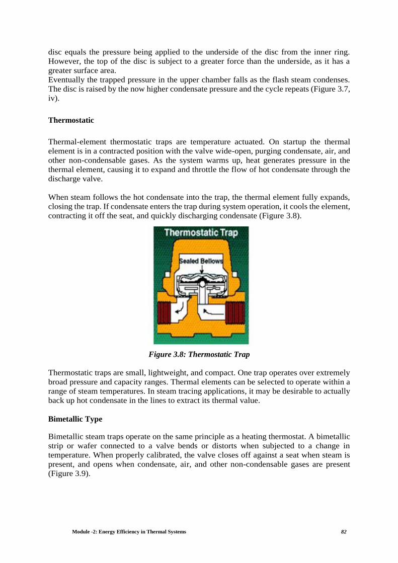
Module -2: Energy Efficiency in Thermal Systems 82
disc equals the pressure being applied to the underside of the disc from the inner ring.
However, the top of the disc is subject to a greater force than the underside, as it has a
greater surface area.
Eventually the trapped pressure in the upper chamber falls as the flash steam condenses.
The disc is raised by the now higher condensate pressure and the cycle repeats (Figure 3.7,
iv).
Thermostatic
Thermal-element thermostatic traps are temperature actuated. On startup the thermal
element is in a contracted position with the valve wide-open, purging condensate, air, and
other non-condensable gases. As the system warms up, heat generates pressure in the
thermal element, causing it to expand and throttle the flow of hot condensate through the
discharge valve.
When steam follows the hot condensate into the trap, the thermal element fully expands,
closing the trap. If condensate enters the trap during system operation, it cools the element,
contracting it off the seat, and quickly discharging condensate (Figure 3.8).
Figure 3.8: Thermostatic Trap
Thermostatic traps are small, lightweight, and compact. One trap operates over extremely
broad pressure and capacity ranges. Thermal elements can be selected to operate within a
range of steam temperatures. In steam tracing applications, it may be desirable to actually
back up hot condensate in the lines to extract its thermal value.
Bimetallic Type
Bimetallic steam traps operate on the same principle as a heating thermostat. A bimetallic
strip or wafer connected to a valve bends or distorts when subjected to a change in
temperature. When properly calibrated, the valve closes off against a seat when steam is
present, and opens when condensate, air, and other non-condensable gases are present
(Figure 3.9).

Module -2: Energy Efficiency in Thermal Systems 83
Figure 3.9: Bimetallic Trap
Advantages of the bimetallic steam trap
Relatively small size for the condensate loads they handle
Resistance to damage from water hammer
A disadvantage is that they must be set, generally at the plant, for a particular steam
operating pressure. If the trap is used for a lower pressure, it may discharge live steam. If
used at a higher steam pressure, it can back up condensate into the system.
Thermostatic traps are often considered a universal steam trap; however, they are normally
not recommended for extremely high condensate requirements (over 7000 kg/hr). For
light-to-moderately high condensate loads, thermostatic steam traps offer advantages in
terms of initial cost, long-term energy conservation, reduced inventory, and ease in
application and maintenance.
Installation of Steam Traps
In most cases, trapping problems are caused by bad installation rather than by the choice
of the wrong type or faulty manufacture. To ensure a trouble-free installation, careful
consideration should be given to the drain point, pipe sizing, air venting, steam locking,
group trapping vs. individual trapping, dirt, water hammer, lifting of the condensate, etc.
1) Drain Point
The drain point should be so arranged that the condensate can easily flow into the trap.
This is not always appreciated. For example, it is useless to provide a 15mm drain hole in
the bottom of a 150 mm steam main, because most of the condensate will be carried away
by the steam velocity. A proper pocket at the lowest part of the pipe line into which the
condensate can drop of at least 100mm diameter is needed in such cases.

Module -2: Energy Efficiency in Thermal Systems 84
Figure 3.10 A: Wrong ways of Draining
Pipes
Figure 3.10 B: Right ways of
Draining Pipes
Figures 3.10 A and 3.10 B show the wrong and the correct practices in providing the drain
points on the steam lines.
2) Pipe Sizing
The pipes leading to and from steam traps should be of adequate size. This is particularly
important in the case of thermodynamic traps, because their correct operation can be
disturbed by excessive resistance to flow in the condensate pipe work. Pipe fittings such
as valves, bends and tees close to the trap will also set up excessive backpressures in certain
circumstances.
3) Air Binding
When air is pumped into the trap space by the steam, the trap function ceases. Unless
adequate provision is made for removing air either by way of the steam trap or a separate
air vent, the plant may take a long time in warming up and may never give its full output.
4) Steam Locking
This is similar to air binding except that the trap is locked shut by steam instead of air. The
typical example is a drying cylinder. It is always advisable to use a float trap provided with
a steam lock release arrangement.
5) Group Trapping vs. Individual Trapping
It is tempting to try and save money by connecting several units to a common steam trap
as shown in Figure 3.11 A. This is known as group trapping. However, it is rarely
successful, since it normally causes water-logging and loss of output.

Module -2: Energy Efficiency in Thermal Systems 85
The steam consumption of a number of units is never the same at a moment of time and
therefore, the pressure in the various steam spaces will also be different. It follows that the
pressure at the drain outlet of a heavily loaded unit will be less than in the case of one that
is lightly or properly loaded. Now, if all these units are connected to a common steam trap,
the condensate from the heavily loaded and therefore lower pressure steam space finds it
difficult to reach the trap as against the higher pressure condensate produced by lightly or
partly loaded unit. The only satisfactory arrangement, thus would be to drain each steam
space with own trap and then connect the outlets of the various traps to the common
condensate return main as shown in above Figure 3.11 B.
Figure 3.11 A: Group Trapping Figure 3.11 B: Individual Trapping
6) Dirt
Dirt is the common enemy of steam traps and the causes of many failures. New steam
systems contain scale, castings, weld metal, piece of packing and jointing materials, etc.
When the system has been in use for a while, the inside of the pipe work and fittings, which
are exposed to corrosive condensate, can get rusted. Thus, rust in the form of a fine brown
powder is also likely to be present. All this dirt will be carried through the system by the
steam and condensate until it reaches the steam trap. Some of it may pass through the trap
into the condensate system without doing any harm, but some dirt will eventually jam the
trap mechanism. It is advisable to use a strainer positioned before the steam trap to prevent
dirt from passing into the system.
7) Water Hammer
A water hammer in a steam system is caused by condensate collection in the plant or pipe
work picked up by the fast moving steam and carried along with it. When this collection
hits obstructions such as bends, valves, steam traps or some other pipe fittings, it is likely
to cause severe damage to fittings and equipment and result in leaking pipe joints.
The problem of water hammer can be eliminated by positioning the pipes so that there is
a continuous slope in the direction of flow. In case of steam mains, a slope of at least 1 m
in every 100 meters is necessary, as also an adequate number of drain points every 30 to
50 meters.
8) Lifting the condensate
It is sometimes necessary to lift condensate from a steam trap to a higher level condensate
return line (Figure 3.12). The condensate will rise up the lifting pipe work when the steam
pressure upstream of the trap is higher than the pressure downstream of the trap.

Module -2: Energy Efficiency in Thermal Systems 86
The pressure downstream of the trap is generally called backpressure, and is made up of
any pressure existing in the condensate line plus the static lift caused by condensate in the
rising pipe work. The upstream pressure will vary between start-up conditions, when it is
at its lowest and running conditions, when it is at its highest.
Backpressure is related to lift by using the following approximate conversion: 1 metre lift
in pipe work = 1 m head static pressure or 0.1 bar backpressure. If a head of 5 m produces
a backpressure of 0.5 bar, then this reduces the differential pressure available to push
condensate through the trap; although under running conditions the reduction in trap
capacity is likely to be significant only where low upstream pressures are used.
In steam mains at start-up, the steam pressure is likely to be very low, and it is common
for water to back-up before the trap, which can lead to water hammer in the space being
drained. To alleviate this problem at start-up, a liquid expansion trap, fitted as shown in
Figure 3.12, will discharge any cold condensate formed at this time to waste.
As the steam main is warmed, the condensate temperature rises, causing the liquid
expansion trap to close. At the same time, the steam pressure rises, forcing the hot
condensate through the ‘working’ drain trap to the return line.
Figure 3.12: Use of a Liquid Expansion Trap
The discharge line from the trap to the overhead return line preferably discharges into the top of the main rather than simply feed to the underside, as shown in Figure 3.12. This assists operation, because although the riser is probably full of water at start-up, it sometimes contains little more than flash steam once hot condensate under pressure passes through. If the discharge line were fitted to the bottom of the return line, it would fill with condensate after each discharge and increase the tendency for water hammer and noise.
It is also recommended that a check valve be fitted after any steam trap from where
condensate is lifted, preventing condensate from falling back towards the trap. The above
general recommendations apply not just to traps lifting condensate from steam mains, but
also to traps draining any type of process running at a constant steam pressure.
Temperature controlled processes will often run with low steam pressures. Rising

Module -2: Energy Efficiency in Thermal Systems 87
condensate discharge lines should be avoided at all costs, unless automatic pump-traps are
used.
Maintenance of steam traps
Dirt is one of the most common causes of steam traps blowing steam. Dirt and scale are
normally found in all steam pipes. Bits of jointing material are also quite common. Since
steam traps are connected to the lowest parts of the system, sooner or later this foreign
matter finds its way to the trap. Once some of the dirt gets logged in the valve seat, it
prevents the valve from shutting down tightly thus allowing steam to escape. The valve
seal should therefore be quickly cleaned, to remove this obstruction and thus prevent steam
loss.
In order to ensure proper working, steam traps should be kept free of pipe-scale and dirt.
The best way to prevent the scale and dirt from getting into the trap is to fit a strainer.
Strainer is a detachable, perforated or meshed screen enclosed in a metal body. It should
be borne in mind that the strainer collects dirt in the course of time and will therefore need
periodic cleaning. It is of course, much easier to clean a strainer than to overhaul a steam
trap.
Figure 3.13: Strainers
At this point, we might mention the usefulness of a sight glass fitted just after a steam trap.
Sight glasses are useful in ascertaining the proper functioning of traps and in detecting
leaking steam traps. In particular, they are of considerable advantage when a number of
steam traps are discharging into a common return line. If it is suspected that one of the
traps is blowing steam, it can be quickly identified by looking through the sight glass.
In most industries, maintenance of steam traps is not a routine job and is neglected unless
it leads to some definite trouble in the plant. In view of their importance as steam savers

Module -2: Energy Efficiency in Thermal Systems 88
and to monitor plant efficiency, the steam traps require considerably more care than is
given.
One may consider a periodic maintenance schedule to repair and replace defective traps in
the shortest possible time, preferable during regular maintenance shut downs in preference
to break down repairs.
Guide to Steam Trap Selection
Actual energy efficiency can be achieved only when
a) Selection
b) Installation and
c) Maintenance of steam traps meet the requirements for the purpose it is installed
The following Table 3.5 gives installation of suitable traps for different process
applications.
Table 3.5 Selection of Steam trap
Application Feature Suitable trap
Steam mains Open to atmosphere,
small capacity
Frequent change in
pressure
Low pressure - high
pressure
Thermodynamic type
Equipment
Reboiler
Heater
Dryer
Heat exchanger etc.
Large capacity
Variation in pressure
and temperature is
undesirable
Efficiency of the
equipment is a problem
Mechanical trap,
Bucket, Inverted
bucket, float
Tracer line
Instrumentation
Reliability with no over
heating
Thermodynamic &
Bimetallic
3.6 Performance Assessment Methods for Steam Traps
Steam trap performance assessment is basically concerned with answering the following
two questions:
Is the trap working correctly or not?
If not, has the trap failed in the open or closed position?
Traps that fail ‘open’ result in a loss of steam and its energy. Where condensate is not
returned, the water is lost as well. The result is significant economic loss, directly via
increased boiler plant costs, and potentially indirectly, via decreased steam heating
capacity.

Module -2: Energy Efficiency in Thermal Systems 89
Traps that fail ‘closed’ do not result in energy or water losses, but can result in significantly
reduced heating capacity and/or damage to steam heating equipment.
Visual Testing
Visual testing includes traps with open discharge sight glasses (Figure 3.13), sight checks,
test tees and three way test valves. In every case, the flow or variation of flow is visually
observed. This method works well with traps that cycle on/off, or dribbles on light load.
On high flow or process, due to the volume of water and flash steam, this method becomes
less viable. If condensate can be diverted ahead of the trap or a secondary flow can be
turned off, the load on the trap will drop to zero or a very minimal amount so the visual
test will allow in determining the leakage.
Figure 3.13: Sight Glass
Sound Testing
Sound testing includes ultrasonic leak detectors (Figure 3.14), mechanics stethoscopes,
screwdriver or metal rod with a human ear against it. All these use the sound created by
flow to determine the trap function like the visual method. This method works best with
traps that cycle on/off or dribbles on light load. Traps which have modulating type
discharge patterns are hard to check on high flows. (Examples are processes, heat
exchangers, air handling coils, etc.). Again by diverting condensate flow ahead of the trap
or shutting off a secondary flow as mentioned under visual testing, the noise level will
drop to zero or a very low level if the trap is operating correctly. If the trap continues to
flow heavily after diversion it would be leaking or blowing through.
Figure 3.14: UltrasonicTesting

Module -2: Energy Efficiency in Thermal Systems 90
Temperature Testing
Temperature testing includes infrared guns (Figure 3.15), surface pyrometers, temperature
tapes, and temperature crayons. Typically they are used to gauge the discharge temperature
on the outlet side of the trap. In the case of temperature tapes or crayon, they are set for a
predetermined temperature and they indicate when temperature exceeds that level. Infrared
guns and surface pyrometer can detect temperatures on both sides of the trap. Both the
infrared and surface pyrometers require bare pipe and a clean surface to achieve a
reasonable reading. The temperature reading will typically be lower than actual internal
pipe temperature due to the fact that steel does have some heat flow resistance. Scale on
the inside of the pipe can also affect the heat transfer. Some of the more expensive infrared
guns can compensate for wall thickness and material differences. Blocked or turned off
traps can easily be detected by infrared guns and surface pyrometers, as they will show
low or cold temperatures. They could also pick up traps which may be undersized or
backing up large amounts of condensate by detecting low temperature readings.
Figure 3.15: Infra Red Testing
3.7 Energy Saving Opportunities
1. Monitoring Steam Traps
For testing a steam trap, there should be an isolating valve provided in the downstream of
the trap and a test valve shall be provided in the trap discharge. When the test valve is
opened, the following points have to be observed:
Condensate discharge-Inverted bucket and thermodynamic disc traps should have
intermittent condensate discharge. Float and thermostatic traps should have a continuous
condensate discharge. Thermostatic traps can have either continuous or intermittent
discharge depending upon the load. If inverted bucket traps are used for extremely small
load, it will have a continuous condensate discharge.
Flash steam-This shall not be mistaken for a steam leak through the trap. The users
sometimes get confused between a flash steam and leaking steam. The flash steam and the
leaking steam can be approximately identified as follows:
If steam blows out continuously in a blue stream, it is a leaking steam.
If a steam floats out intermittently in a whitish cloud, it is a flash steam.

Module -2: Energy Efficiency in Thermal Systems 91
2. Continuous steam blow and no flow indicate there is a problem in the trap.
Whenever a trap fails to operate and the reasons are not readily apparent, the discharge
from the trap should be observed. A step-by-step analysis has to be carried out mainly with
reference to lack of discharge from the trap, steam loss, continuous flow, sluggish heating,
to find out whether it is a system problem or the mechanical problem in the steam trap.
3. Avoiding Steam Leakages
Steam leakage is a visible indicator of waste and must be avoided. It has been estimated
that a 3 mm diameter hole on a pipeline carrying 7kg/cm2 steam would waste 33 Kilo Litre
of fuel oil per year. Steam leaks on high-pressure mains are prohibitively costlier than on
low pressure mains. Any steam leakage must be quickly attended to. In fact, the plant
should consider a regular surveillance programme for identifying leaks at pipelines, valves,
flanges and joints. Indeed, by plugging all leakages, one may be surprised at the extent of
fuel savings, which may reach up to 5% of the steam consumption in a small or medium
scale industry or even higher in installations having several process departments.
Figure 3.16: Steam Loss vs Plume Length
To avoid leaks it may be worthwhile considering replacement of the flanged joints which
are rarely opened in old plants by welded joints. Figure 3.16 provides a quick estimate for
steam leakage based on plume length.
Example 3.6
Plume Length = 700 mm
Steam loss = 10 kg/h
The following Table 3.6 highlights the significance of loss through steam leaks.
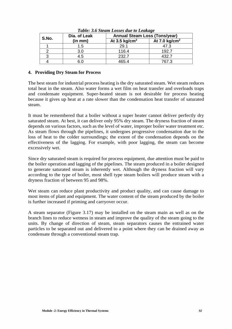
Module -2: Energy Efficiency in Thermal Systems 92
Table: 3.6 Steam Losses due to Leakage
S.No. Dia. of Leak
(in mm)
Annual Steam Loss (Tons/year)
At 3.5 kg/cm2 At 7.0 kg/cm2
1 1.5 29.1 47.3
2 3.0 116.4 192.7
3 4.5 232.7 432.7
4 6.0 465.4 767.3
4. Providing Dry Steam for Process
The best steam for industrial process heating is the dry saturated steam. Wet steam reduces
total heat in the steam. Also water forms a wet film on heat transfer and overloads traps
and condensate equipment. Super-heated steam is not desirable for process heating
because it gives up heat at a rate slower than the condensation heat transfer of saturated
steam.
It must be remembered that a boiler without a super heater cannot deliver perfectly dry
saturated steam. At best, it can deliver only 95% dry steam. The dryness fraction of steam
depends on various factors, such as the level of water, improper boiler water treatment etc.
As steam flows through the pipelines, it undergoes progressive condensation due to the
loss of heat to the colder surroundings; the extent of the condensation depends on the
effectiveness of the lagging. For example, with poor lagging, the steam can become
excessively wet.
Since dry saturated steam is required for process equipment, due attention must be paid to
the boiler operation and lagging of the pipelines. The steam produced in a boiler designed
to generate saturated steam is inherently wet. Although the dryness fraction will vary
according to the type of boiler, most shell type steam boilers will produce steam with a
dryness fraction of between 95 and 98%.
Wet steam can reduce plant productivity and product quality, and can cause damage to
most items of plant and equipment. The water content of the steam produced by the boiler
is further increased if priming and carryover occur.
A steam separator (Figure 3.17) may be installed on the steam main as well as on the
branch lines to reduce wetness in steam and improve the quality of the steam going to the
units. By change of direction of steam, steam separators causes the entrained water
particles to be separated out and delivered to a point where they can be drained away as
condensate through a conventional steam trap.
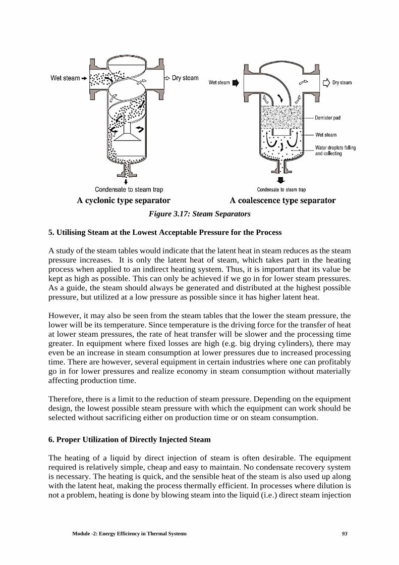
Module -2: Energy Efficiency in Thermal Systems 93
Figure 3.17: Steam Separators
5. Utilising Steam at the Lowest Acceptable Pressure for the Process
A study of the steam tables would indicate that the latent heat in steam reduces as the steam
pressure increases. It is only the latent heat of steam, which takes part in the heating
process when applied to an indirect heating system. Thus, it is important that its value be
kept as high as possible. This can only be achieved if we go in for lower steam pressures.
As a guide, the steam should always be generated and distributed at the highest possible
pressure, but utilized at a low pressure as possible since it has higher latent heat.
However, it may also be seen from the steam tables that the lower the steam pressure, the
lower will be its temperature. Since temperature is the driving force for the transfer of heat
at lower steam pressures, the rate of heat transfer will be slower and the processing time
greater. In equipment where fixed losses are high (e.g. big drying cylinders), there may
even be an increase in steam consumption at lower pressures due to increased processing
time. There are however, several equipment in certain industries where one can profitably
go in for lower pressures and realize economy in steam consumption without materially
affecting production time.
Therefore, there is a limit to the reduction of steam pressure. Depending on the equipment
design, the lowest possible steam pressure with which the equipment can work should be
selected without sacrificing either on production time or on steam consumption.
6. Proper Utilization of Directly Injected Steam
The heating of a liquid by direct injection of steam is often desirable. The equipment
required is relatively simple, cheap and easy to maintain. No condensate recovery system
is necessary. The heating is quick, and the sensible heat of the steam is also used up along
with the latent heat, making the process thermally efficient. In processes where dilution is
not a problem, heating is done by blowing steam into the liquid (i.e.) direct steam injection

Module -2: Energy Efficiency in Thermal Systems 94
is applied. If the dilution of the tank contents and agitation are not acceptable in the process
(i.e.) direct steam agitation are not acceptable, indirect steam heating is the only answer.
Figure 3.18: Temperature Control for Directly Injected Steam
Ideally, the injected steam should be condensed completely as the bubbles rise through the
liquid. This is possible only if the inlet steam pressures are kept very low - around 0.5
kg/cm2-and certainly not exceeding 1 kg/cm2. If pressures are high, the velocity of the
steam bubbles will also be high and they will not get sufficient time to condense before
they reach the surface. Figure 3.18 shows a recommended arrangement for direct injection
of steam.
A large number of small diameter holes (2 to 5mm), facing downwards, should be drilled
on the separate pipe. This will help in dissipating the velocity of bubbles in the liquid. A
thermostatic control of steam admitted is highly desirable.
7. Minimising Heat Transfer Barriers
The metal wall may not be the only barrier in a heat transfer process. There is likely to be
a film of air, condensate and scale on the steam side. On the product side, there may also
be baked-on product or scale, and a stagnant film of product.
Agitation of the product may eliminate the effect of the stagnant film, whilst regular
cleaning on the product side should reduce the scale.
Regular cleaning of the surface on the steam side may also increase the rate of heat transfer
by reducing the thickness of any layer of scale; however, this may not always be possible.
This layer may also be reduced by careful attention to the correct operation of the boiler,
and the removal of water droplets carrying impurities from the boiler.

Module -2: Energy Efficiency in Thermal Systems 95
Figure 3.19: Heat Transfer Barriers
The elimination of the condensate film is not quite as simple. As the steam condenses to
give up its enthalpy of evaporation, droplets of water may form on the heat transfer surface.
These may merge together to form a continuous film of condensate. The condensate film
may be between 100 and 150 times more resistant to heat transfer than a steel heating
surface, and 500 to 600 times more resistant than copper.
As air is a good insulator, it provides even more resistance to heat transfer. Air may be
between 1500 and 3000 times more resistant to heat flow than steel, and 8000 to 16000
more resistant than copper. This means that a film of air only 0.025 mm thick may resist
as much heat transfer as a wall of copper 400 mm thick. These comparative relationships
depend on the temperature profiles across each layer.
Figure 3.19 illustrates the effect this combination of layers has on the heat transfer process.
These barriers to heat transfer not only increase the thickness of the entire conductive layer,
but also greatly reduce the mean thermal conductivity of the layer.
The more resistant the layer to heat flow, the larger the temperature gradient is likely to
be. This means that to achieve the same desired product temperature, the steam pressure
may need to be significantly higher.
To achieve the desired product output and minimise the cost of process steam operations,
a high heating performance may be maintained by reducing the thickness of the films on
the condensing surface and removal of air from the supply steam.
8. Proper Air Venting
When steam is first admitted to a pipe after a period of shutdown, the pipe is full of air.
Further, amounts of air and other non-condensable gases will enter with the steam,
although the proportions of these gases are normally very small compared with the steam.
When the steam condenses, these gases will accumulate in pipes and heat exchangers.
Precautions should be taken to discharge them. The consequence of not removing air is a
lengthy warming up period, reduction in plant efficiency and process performance. Air in
the steam system will also affect the system temperature. Air will exert its own pressure
within the system, which will add to the pressure of the steam to give a total pressure.

Module -2: Energy Efficiency in Thermal Systems 96
A layer of air only 1 mm thick can offer the same resistance to heat as a layer of water 25
µm thick, a layer of iron 2 mm thick or a layer of copper 15 mm thick. It is very important
therefore to remove air from any steam system.
Figure 3.20: Air Vent
Automatic air vents for steam systems (which operate on the same principle as thermostatic
steam traps) should be fitted above the condensate level so that only air or steam-air
mixtures can reach them. The best location for them is at the end of the steam mains. In
addition to air venting at the end of a main, air vents should also be fitted in parallel with
an inverted bucket trap or a thermodynamic trap.
9. Condensate Recovery
The steam condenses after giving off its latent heat in the heating coil or the jacket of the
process equipment. A sizable portion (about 25%) of the total heat in the steam leaves the
process equipment as hot water. If this water is returned to the boiler house, it will reduce
the fuel requirements of the boiler. For every 6 0C rise in the feed water temperature, there
will be approximately 1% saving of fuel in the boiler. However, in most cases, the boiler
water has to be chemically treated to prevent or reduce scale formation, whereas the
condensate is almost entirely pure water which needs no treatment. With a good percentage
of the condensate returning to the boiler house, the expenses involved for water treatment
will be reduced by an appreciable amount.
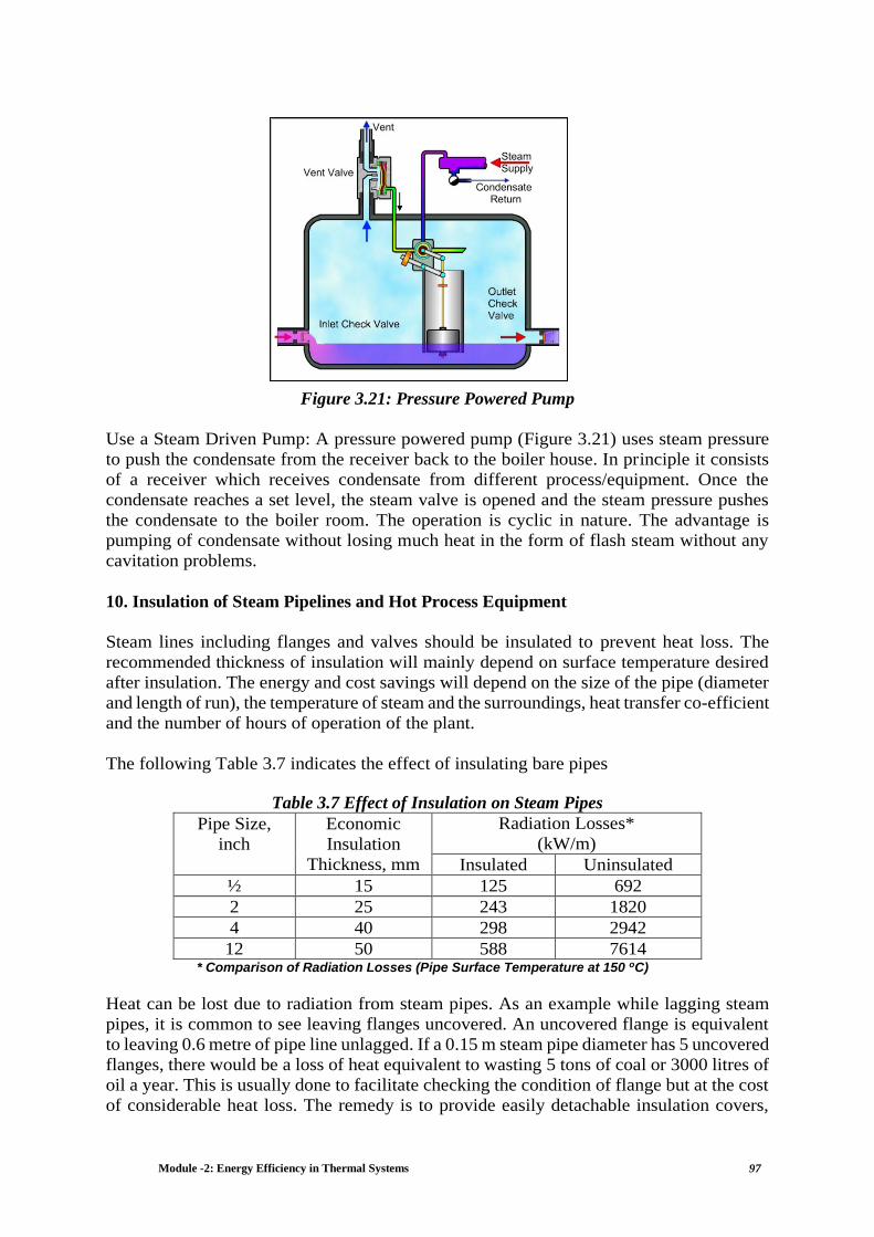
Module -2: Energy Efficiency in Thermal Systems 97
Figure 3.21: Pressure Powered Pump
Use a Steam Driven Pump: A pressure powered pump (Figure 3.21) uses steam pressure
to push the condensate from the receiver back to the boiler house. In principle it consists
of a receiver which receives condensate from different process/equipment. Once the
condensate reaches a set level, the steam valve is opened and the steam pressure pushes
the condensate to the boiler room. The operation is cyclic in nature. The advantage is
pumping of condensate without losing much heat in the form of flash steam without any
cavitation problems.
10. Insulation of Steam Pipelines and Hot Process Equipment
Steam lines including flanges and valves should be insulated to prevent heat loss. The
recommended thickness of insulation will mainly depend on surface temperature desired
after insulation. The energy and cost savings will depend on the size of the pipe (diameter
and length of run), the temperature of steam and the surroundings, heat transfer co-efficient
and the number of hours of operation of the plant.
The following Table 3.7 indicates the effect of insulating bare pipes
Table 3.7 Effect of Insulation on Steam Pipes
Pipe Size,
inch
Economic
Insulation
Thickness, mm
Radiation Losses*
(kW/m)
Insulated Uninsulated
½ 15 125 692
2 25 243 1820
4 40 298 2942
12 50 588 7614 * Comparison of Radiation Losses (Pipe Surface Temperature at 150 oC)
Heat can be lost due to radiation from steam pipes. As an example while lagging steam
pipes, it is common to see leaving flanges uncovered. An uncovered flange is equivalent
to leaving 0.6 metre of pipe line unlagged. If a 0.15 m steam pipe diameter has 5 uncovered
flanges, there would be a loss of heat equivalent to wasting 5 tons of coal or 3000 litres of
oil a year. This is usually done to facilitate checking the condition of flange but at the cost
of considerable heat loss. The remedy is to provide easily detachable insulation covers,

Module -2: Energy Efficiency in Thermal Systems 98
which can be easily removed when necessary. The various insulating materials used are
cork, Glass wool, Rock wool and Asbestos.
Effect of insulation of flanges: 12 Flanges of 150 mm diameter.
Heat loss in the following 2 cases:
Case (I) – Bare flanges
Case (II) – Flanges with 50 mm insulation and aluminum cladding
Table 3.8 Comparison between Case (I) and Case (II)
Parameter Unit Case (I) Case (II)
Heat Loss kcal/year 36,300 4,100
Steam Loss kg/Year 68 3.2
Fuel Loss kg/Year 55 0.26
Energy Saving Potential Rs. Per Year 60 2.8
11. Flash Steam Recovery
Flash steam is produced when condensate at a high pressure is released to a lower pressure
and can be used for low pressure heating.
The higher the steam pressure and lower the flash steam pressure the greater the quantity
of flash steam that can be generated. In many cases, flash steam from high pressure
equipment is made use of directly on the low pressure equipment to reduce use of steam
through pressure reducing valves.
The flash steam quantity can be calculated by the following formula with the help of a
steam table:
Flash steam available % =2
21
L
SS
Where,
S1 is the sensible heat of higher pressure condensate.
S2 is the sensible heat of the steam at lower pressure (at which it has been flashed).
L2 is the latent heat of flash steam (at lower pressure).
Example 3.7 Calculating the amount of flash steam from condensate
Hot condensate at 7 bar g has a heat content of about 721 kJ/kg. When it is released to
atmospheric pressure (0 bar g), each kilogram of water can only retain about 419 kJ of
heat. The excess energy in each kilogram of the condensate is therefore 721 – 419 = 302
kJ. This excess energy is available to evaporate some of the condensate into steam, the
amount evaporated being determined by the proportion of excess heat to the amount of
heat required to evaporate water at the lower pressure, which in this example, is the
enthalpy of evaporation at atmospheric pressure, 2258 kJ/kg.
Therefore, in this example, the percentage of flash steam evaporated = (302/2258)*100%
Flash steam evaporated = 13.4%

Module -2: Energy Efficiency in Thermal Systems 99
The amount of flash steam in the pipe is the most important factor when sizing trap
discharge lines.
Figure 3.28: Quantity of Flash Steam Graph
Flash steam can be used on low pressure applications like direct injection and can replace
an equal quantity of live steam that would be otherwise required. The demand for flash
steam should exceed its supply, so that there is no buildup of pressure in the flash vessel
and the consequent loss of steam through the safety valve. Generally, the simplest method
of using flash steam is to flash from a machine/equipment at a higher pressure to a
machine/equipment at a lower pressure, thereby augmenting steam supply to the low
pressure equipment.
In general, a flash system should run at the lowest possible pressure so that the maximum
amount of flash is available and the backpressure on the high pressure systems is kept as
low as possible.

Module -2: Energy Efficiency in Thermal Systems 100
Flash steam from the condensate can be separated in an equipment called the ‘flash vessel’.
This is a vertical vessel as shown in the Figure 3.22. The diameter of the vessel is such
that a considerable drop in velocity allows the condensate to fall to the bottom of the vessel
from where it is drained out by a steam trap preferably a float trap. Flash steam itself rises
to leave the vessel at the top. The height of the vessel should be sufficient enough to avoid
water being carried over in the flash steam.
Figure 3.22: Flash Steam Recovery
The condensate from the traps (A) along with some flash steam generated passes through
vessel (B). The flash steam is let out through (C) and the residual condensate from (B)
goes out through the steam trap (D). The flash vessel is usually fitted with a ‘pressure
gauge’ to know the quality of flash steam leaving the vessel. A ‘safety valve’ is also
provided to vent out the steam in case of high pressure build up in the vessel.
12. Pipe Redundancy
All redundant (piping which are no longer needed) pipelines must be eliminated, which
could be, at times, up to 10-15 % of total length. This would reduce steam distribution
losses significantly. The pipe routing shall be made for transmission of steam in the
shortest possible way, so as to reduce the pressure drop in the system, thus saving the
energy. However, care should be taken that, the pipe routing shall be flexible enough to
take thermal expansion and to keep the terminal point loads, within the allowable limit.
13. Reducing the Work to be done by Steam
The equipment should be supplied with steam as dry as possible. The plant should be made
efficient. For example, if any product is to be dried such as in a laundry, a press could be
used to squeeze as much water as possible before being heated up in a dryer using steam.
When the steam reaches the place where its heat is required, it must be ensured that the
steam has no more work to do than is absolutely necessary. Air-heater batteries, for
example, which provide hot air for drying, will use the same amount of steam whether the

Module -2: Energy Efficiency in Thermal Systems 101
plant is fully or partly loaded. So, if the plant is running only at 50 per cent load, it is
wasting twice as much steam (or twice as much fuel) than necessary.
Figure 3.23 Steam Wastage Due to Insufficient Mechanical Drying
The energy saving is affected by following measures:
Reduction in operating hours
Reduction in steam quantity required per hour
Use of more efficient technology
Minimizing wastage.
Always use the most economical way to removing the bulk of water from the wet material.
Steam can then be used to complete the process. For this reason, hydro-extractors, spin
dryers, squeeze or calendar rolls, presses, etc. are initially used in many drying processes
to remove the mass of water. The efficiency with which this operation is carried out is
most important. For example, in a laundry for finishing sheets (100 kg/hr dry weight), the
normal moisture content of the sheets as they leave the hydro extractor is 48% by weight.
Thus, the steam heated iron has to evaporate nearly 48 kg of water. This requires 62 kg of
steam. If, due to inefficient drying in the hydro-extractor, the steam arrive at the iron with
52% moisture content i.e. 52 kg of water has to be evaporated, requiring about 67 kg of
steam. So, for the same quantity of finished product, the steam consumption increases by
8 per cent. This is illustrated in Figure 3.23.
Examples 3.8 In a crude distillation unit of a refinery, 50 MT/hr of crude is heated using saturated steam
in a heat exchanger from 35°C to 85°C. Plant is operating for 8000 hrs/annum. Consider
specific heat of the crude as 0.631 kCal/kg°C. The plant has two steam headers operating
at 3 bar and 8 bar respectively, passing nearby the heat exchanger. Cost of steam is same
for both 3 bar and 8 bar @ BDT.4.50/kg.
Module -2: Energy Efficiency in Thermal Systems 102
As an Energy Manager, which of the following options will you recommend to the unit
based on the annual cost of steam?
a) Utilising 3 bar steam
b) Utilising 8 bar steam
Given: Data from steam table:
Steam Pressure, bar Enthalpy kCal/kg
Water Evaporation Steam
3.0 133 517 650
8.0 171 489 660
Solution
Heat gain in crude = m * Cp * del T
Heat gain in crude = 50 * 1000 * 0.631 * (85 – 35)
Heat gain in crude = 1577500 kCal/hr
Heat gain in crude = heat loss in steam
Heat loss in steam = mass of the steam * latent heat of steam
Option A:
3 bar pressure steam having 517 kCal/kg of latent heat
Mass of the steam = 1577500 / 517
Mass of the steam = 3051 kg / hr
Cost of steam expenditure = 3051 * 8000 * 4.5
Cost of steam expenditure = 10.98 Crore BDT
Option B:
8 bar pressure steam having 489 Kcal/kg of latent heat
Mass of the steam = 1577500 / 489
Mass of the steam = 3225 kg / hr
Cost of steam expenditure = 3226 * 8000 * 4.5
Cost of steam expenditure = 11.61 Crore BDT
Recommendation: Option A is recommended as it is found to be economical (Steam @ 3
bar pressure) since the expenditure per annum is less when compared to Option B.
Example 3.9
In a process plant, 20 TPH of steam after pressure reduction with pressure reducing valve
to 20 kg/cm2 gets superheated. The temperature of steam is 280oC. The management wants
to install a de-super heater to convert superheated steam into saturated steam at 20 kg/cm2
for process use, and its saturation temperature is 210oC.
Calculate quantity of water at 30oC to be injected in de-super heater to get the desired
saturated steam using the following data.
Specific heat of superheated steam = 0.45 kCal/KgoC
Latent heat of steam at 20 kg/cm2 = 450 kCal/kg

Module -2: Energy Efficiency in Thermal Systems 103
Solution
Quantity of heat available above saturation = 20,000 x 0.45 x (280-210)
= 6,30,000kCal
Quantity of water required in de-superheater = Q x {1x (210-30) + 450} = 630000 = 1000 kg/hr

Module -2: Energy Efficiency in Thermal Systems 104
Chapter 4: Industrial Furnaces A furnace is an equipment to melt metals for casting or heat materials for change of shape
(rolling, forging etc.) or change of properties (heat treatment).
4.1 Types and Classification of Different Furnaces
Based on the method of generating heat, furnaces are broadly classified into two types
namely combustion type (using fuels) and electric type. The combustion type furnace can
be broadly classified as oil fired, coal fired or gas fired.
Based on the mode of charging of material furnaces can be classified as (i) Intermittent or
Batch type furnace or Periodical furnace and (ii) Continuous furnace.
Based on mode of waste heat recovery as recuperative and regenerative furnaces.
Another type of furnace classification is made based on mode of heat transfer, mode of
charging and mode of heat recovery as shown in the figure 4.1 below.
Figure 4.1: Furnace Classification
The electric furnaces can be broadly classified as resistance type for heating and induction
and arc furnace for melting of metals.
Characteristics of an Efficient Furnace
Furnace should be designed so that in a given time, as much of material as possible can be
heated to a uniform temperature as possible with the least possible fuel and labour. To
achieve this end, the following parameters can be considered.
Determination of the quantity of heat to be imparted to the material or charge.
Liberation of sufficient heat within the furnace to heat the stock and overcome all
heat losses.
According
to mode of
heat
transfer
Heated through Medium
Forging
Furnace
classification
According
to mode of
charging
Pot
Glass tank
melting
Module -2: Energy Efficiency in Thermal Systems 105
Transfer of available part of that heat from the furnace gases to the surface of the
heating stock.
Equalization of the temperature within the stock.
Reduction of heat losses from the furnace to the minimum possible extent.
Furnace Energy Supply
Since the products of flue gases directly contact the stock, type of fuel chosen is of
importance. For example, some materials will not tolerate sulphur in the fuel. Also use of
solid fuels will generate particulate matter, which will interfere the stock placed inside the
furnace. Hence, vast majority of the furnaces use liquid fuel, gaseous fuel or electricity as
energy input. Electricity is used in induction and arc furnaces for melting steel and cast
iron. Non-ferrous melting utilizes oil as fuel.
Oil Fired Furnace
Furnace oil is the major fuel used in oil fired furnaces, especially for reheating and heat
treatment of materials. LDO is used in furnaces where presence of sulphur is undesirable.
The key to efficient furnace operation lies in complete combustion of fuel with minimum
excess air.
Furnaces operate with efficiencies as low as 7% as against upto 90% achievable in other
combustion equipment such as boiler. This is because of the high temperature at which the
furnaces have to operate to meet the required demand. For example, a furnace heating the
stock to 1200oC will have its exhaust gases leaving at least at 1200oC resulting in a huge
heat loss through the stack. However, improvements in efficiencies have been brought
about by methods such as preheating of stock, preheating of combustion air and other
waste heat recovery systems.
Characteristics of an Efficient Furnace
Furnace should be designed so that in a given time, as much of material as possible can be
heated to a uniform temperature as possible with the least possible fuel and labour. To
achieve this end, the following parameters can be considered.
Determination of the quantity of heat to be imparted to the material or charge.
Liberation of sufficient heat within the furnace to heat the stock and overcome all
heat losses.
Transfer of available part of that heat from the furnace gases to the surface of the
heating stock.
Equalisation of the temperature within the stock.
Reduction of heat losses from the furnace to the minimum possible extent.
Furnace Energy Supply
Since the products of flue gases directly contact the stock, type of fuel chosen is of
importance. For example, some materials will not tolerate sulphur in the fuel. Also use of solid
fuels will generate particulate matter, which will interfere with the stock place inside the
furnace. Hence, vast majority of the furnaces use liquid fuel, gaseous fuel or electricity as

Module -2: Energy Efficiency in Thermal Systems 106
energy input. Electricity is used in induction and arc furnaces for melting steel and cast iron.
Non-ferrous melting utilizes oil as fuel.
Oil Fired Furnace
Furnace oil is the major fuel used in oil fired furnaces, especially for reheating and heat
treatment of materials. LDO is used in furnaces where presence of sulphur is undesirable. The
key to efficient furnace operation lies in complete combustion of fuel with minimum excess
air.
Furnaces operate with efficiencies as low as 7% as against upto 90% achievable in other
combustion equipment such as boiler. This is because of the high temperature at which the
furnaces have to operate to meet the required demand. For example, a furnace heating the stock
to 1200 °C will have its exhaust gases leaving at least at 1200 °C resulting in a huge heat loss
through the stack. However, improvements in efficiencies have been brought about by methods
such as preheating of stock, preheating of combustion air and other waste heat recovery
systems.
Typical Furnace System
i) Forging Furnaces
The forging furnace is used for preheating billets and blooms to attain a 'forge' temperature.
The furnace temperature is maintained at around 1200 to 1250 °C. Forging furnaces use an open
fireplace system and most of the heat is transmitted by radiation.
The total operating cycle can be divided into (a) heat up time (b) soaking time and (c)
forging time.
Normally, large pieces are soaked for 4 to 6 hrs inside the furnace to attain uniform
temperature throughout the cross-section of the material. The actual soaking time varies
with the type and thickness of the material. The completely soaked material is withdrawn
from furnace to the hammer to be forged as required. Larger pieces may have to be
reheated several times. A typical forging furnaces is illustrated in Figure 4.2.
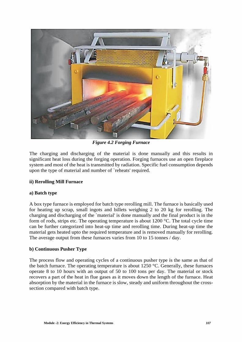
Module -2: Energy Efficiency in Thermal Systems 107
Figure 4.2 Forging Furnace
The charging and discharging of the material is done manually and this results in
significant heat loss during the forging operation. Forging furnaces use an open fireplace
system and most of the heat is transmitted by radiation. Specific fuel consumption depends
upon the type of material and number of `reheats' required.
ii) Rerolling Mill Furnace
a) Batch type
A box type furnace is employed for batch type rerolling mill. The furnace is basically used
for heating up scrap, small ingots and billets weighing 2 to 20 kg for rerolling. The
charging and discharging of the `material' is done manually and the final product is in the
form of rods, strips etc. The operating temperature is about 1200 °C. The total cycle time
can be further categorized into heat-up time and rerolling time. During heat-up time the
material gets heated upto the required temperature and is removed manually for rerolling.
The average output from these furnaces varies from 10 to 15 tonnes / day.
b) Continuous Pusher Type
The process flow and operating cycles of a continuous pusher type is the same as that of
the batch furnace. The operating temperature is about 1250 °C. Generally, these furnaces
operate 8 to 10 hours with an output of 50 to 100 tons per day. The material or stock
recovers a part of the heat in flue gases as it moves down the length of the furnace. Heat
absorption by the material in the furnace is slow, steady and uniform throughout the cross-
section compared with batch type.

Module -2: Energy Efficiency in Thermal Systems 108
iii) Continuous Steel Reheating Furnaces
The main function of a reheating furnace is to raise the temperature of a piece of steel,
typically to between 900 °C and 1250 °C, until it is plastic enough to be pressed or rolled
to the desired section, size or shape, The furnace must also meet specific requirements and
objectives in terms of stock heating rates for metallurgical and productivity reasons. In
continuous reheating, the steel stock forms a continuous flow of material and is heated to
the desired temperature as it travels through the furnace.
All furnaces possess the features shown in Figure 4.3
Figure 4.3 Furnace Feature
A refractory chamber constructed of insulating materials for retaining heat at the
high operating temperatures.
A hearth to support or carry the steel. This can consist of refractory materials or an
arrangement of metallic supports that may be water-cooled.
Burners that use liquid or gaseous fuels to raise and maintain the temperature in the
chamber. Coal or electricity can be used for reheating. A method of removing the
combustion exhaust gases from the chamber
A method of introducing and removing the steel from the chamber.
These facilities depend on the size and type of furnace, the shape and size of the
steel being processed, and the general layout of the rolling mill.
Common systems include roller tables, conveyors, charging machines and furnace
pushers.
Heat Transfer in Furnaces
The main ways in which heat is transferred to the steel in a reheating furnace are shown in
Figure 4.4. In simple terms, heat is transferred to the stock by:

Module -2: Energy Efficiency in Thermal Systems 109
✓ Radiation from the flame, hot combustion products and the furnace walls and roof;
✓ Convection due to the movement of hot gases over the stock surface.
At the high temperatures employed in reheating furnaces, the dominant mode of heat
transfer is wall radiation. Heat transfer by gas radiation is dependent on the gas
composition (mainly the carbon dioxide and water vapour concentrations), the temperature
and the geometry of the furnace.
Figure 4.4: Heat Transfer in furnace
Types of Continuous Reheating Furnace
Continuous reheating furnaces are primarily categorised by the method by which stock is
transported through the furnace. There are two basic methods:
Stock is butted together to form a stream of material that is pushed through
the furnace. Such furnaces are called pusher type furnaces.
Stock is placed on a moving hearth or supporting structure which transports
the steel through the furnace. Such types include walking beam, walking
hearth, rotary hearth and continuous recirculating bogie furnaces.
The major consideration with respect to furnace energy use is that the inlet and outlet
apertures should be minimal in size and designed to avoid air infiltration.
i) Pusher Type Furnaces
The pusher type furnace is popular in steel industry. It has relatively low installation and
maintenance costs compared to moving hearth furnaces. The furnace may have a solid
hearth, but it is also possible to push the stock along skids with water-cooled supports that

Module -2: Energy Efficiency in Thermal Systems 110
allow both the top and bottom faces of the stock to the heated. The design of a typical
pusher furnace design is shown schematically in Figure 4.5.
Figure 4.5: Pusher Type Furnace
Pusher type furnaces, however, do have some disadvantages, including:
✓ Frequent damage of refractory hearth and skid marks on material
✓ Water cooling energy losses from the skids and stock supporting structure in top and
bottom fired furnaces have a detrimental effect on energy use;
✓ Discharge must be accompanied by charge:
✓ Stock sizes and weights and furnace length are limited by friction and the possibility of
stock pile-ups.
✓ All round heating of the stock is not possible.
ii) Walking Hearth Furnaces
The walking hearth furnace (Figure.4.6) allows the stock to be transported through the
furnace in discrete steps. Such furnaces have several attractive features, including:
simplicity of design, ease of construction, ability to cater for different stock sizes (within
limits), negligible water cooling energy losses and minimal physical marking of the stock.
The main disadvantage of walking hearth furnaces is that the bottom face of the stock
cannot be heated. This can be alleviated to some extent by maintaining large spaces
between pieces of stock. Small spaces between the individual stock pieces limits the
heating of the side faces and increases the potential for unacceptable temperature
differences within the stock at discharge. Consequently, the stock residence time may be
long, possibly several hours; this may have an adverse effect on furnace flexibility and the
yield may be affected by scaling.

Module -2: Energy Efficiency in Thermal Systems 111
Figure 4.6 Walking Hearth Type Furnace
iii) Rotary hearth furnace
The rotary hearth furnace (Figure 4.7) has tended to supersede the re-circulating bogie
type. The heating and cooling effects introduced by the bogies are eliminated, so heat
storage losses are less. The rotary hearth has, however a more Burners complex design
with an annular shape and revolving hearth.
Figure 4.7 Rotary Hearth Furnace

Module -2: Energy Efficiency in Thermal Systems 112
iv) Continuous Recirculating Bogie type Furnaces
These types of moving hearth type furnaces tend to be used for compact stock of variable
size and geometry. In bogie furnaces (Figure 4.8), the stock is placed on a bogie with a
refractory hearth, which travels through the furnace with others in the form of a train. The
entire furnace length is always occupied by bogies. Bogie furnaces tend to be long and
narrow and to suffer from problems arising from inadequate sealing of the gap between
the bogies and furnace shell, difficulties in removing scale, and difficulties in firing across
a narrow hearth width.
Figure 4.8 Continuous Circulating Bogie Type Furnace
v) Walking Beam Furnaces:
The walking beam furnace (Figure 4.9) overcomes many of the problems of pusher
furnaces and permits heating of the bottom face of the stock. This allows shorter stock
heating times and furnace lengths and thus better control of heating rates, uniform stock
discharge temperatures and operational flexibility. In common with top and bottom fired
pusher furnaces, however, much of the furnace is below the level of the mill; this may be
a constraint in some applications.

Module -2: Energy Efficiency in Thermal Systems 113
Figure 4.9 Walking Beam Furnace
vi) Cupola Furnace
A cupola furnace (Figure 4.10) is tall, cylindrical cast iron, foundry returns. The charge
used in cupola furnace consists of alternate layers of coke, flux and metal (iron). These
three components are continuously built into the cupola furnace. The most commonly used
iron - to - coke ratio is 8:1. The flux may be limestone (CaCO3), fluorspar, sodium
carbonate or calcium carbide. Limestone is the commonly employed flux. The total weight
of the flux will be approximately 1/5th the weight of the coke charge. Sufficient air is
passed through the tuyeres for proper combustion of coke.
Melting in Cupola Furnace
Cupola furnace works on the counter current principle. As the combustion takes place, the
charge materials (coke, flux and metal) will be descending downwards, while the hot gases
due to combustion will be ascending upwards. Heat exchange takes place between the
rising hot gases and the descending charge thereby melting the metal. The liquid metal
drops down, while the coke floats up on top of it.

Module -2: Energy Efficiency in Thermal Systems 114
Figure 4.10 Cupola Furnace
The flux also melts and reacts with the impurities of the molten metal forming a slag. The
slag floats on the surface of the molten metal thereby preventing oxidation of the metal.
Zones of Cupola Furnace
Well zone in Cupola Furnace
Well zone in the portion situated between the rammed sand bottom and just below the
bottom edge of the tuyeres. The molten metal is occupied in this zone.
Combustion Zone in Cupola Furnace
The combustion zone or oxidizing zone is situated normally 15-30 cm from the bottom
edge of the tuyeres. It is in this zone where rapid combustion of coke takes place due to
which a lot of heat is generated in the furnace. The combustion is rapid due to the supply
of blast air through the tuyeres.
Oxidation of manganese and silicon evolve still more heat. The reactions which take place
in this zone are:
C + 02 (from air) → CO2 + heat
2 Mn+02 → 2 MnO + heat
Si+02 → SiO2 + heat
The temperature in this zone varies from 155 °C -185 °C

Module -2: Energy Efficiency in Thermal Systems 115
Reducing zone or protection zone is the portion located from the top of the combustion
zone to the top of the coke bed. In this zone, some of the hot CO2 gas moving upward through
the hot coke gets reduced to CO. In other words, reduction of CO2 to CO occurs in this zone.
Due to the reducing atmosphere, the charge is protected from oxidation. The reaction taking
place in this zone is given by.
CO2 + C (coke) → 2 CO - Heat
Due to the reduction, the temperature reduces to around 1200 °C in this zone.
Melting Zone in Cupola Furnace
The portion located just above the coke bed to the top of the metal (iron) is called the
melting zone. The metal starts melting in this zone and trickles down through the coke bed
to the well zone. The molten iron while passing down through the reducing zone picks up
carbon and the reaction is given by:
3 Fe + 2 CO → Fe3C + CO2
Preheating zone in Cupola Furnace
The portion occupied from the top surface of the melting zone to the charging door is
called 'Preheating zone'. The hot gases rising upwards from the combustion and reducing
zone gives its heat to the charge before passing out of the furnace. Thus, the charge is
preheated before descending downwards
Hot Blast Cupola
The temperature of exhaust gas of a cupola is as high as 800 °C, making it possible to preheat
blast air up to as high as 400 °C by heat exchange. In addition, both the sensible and latent
heat of exhaust gas can be recycled for preheating blast air by combustion of CO gas
included in exhaust gas. When blast air is preheated to 300 °C or higher, the sensible heat of blast
air is added to heat input, activating combustion of coke, leading to the rise in combustion
temperature.
vii) Induction Furnaces
Induction furnaces are ideal for melting and alloying a wide variety of metals with minimum
melt losses, however, little refining of the metal is possible. There are two main types of
induction furnace: coreless and channel, the principle of operation of which are the same.
Coreless Induction Furnace
Coreless induction furnace (Figure 4.11) consists of: a water cooled helical coil made of a
copper tube, a crucible installed within the coil and supporting shell equipped with
trunnions on which the furnace may tilt. Alternating current passing through the coil
induces alternating currents in the metal charge loaded to the crucible. These induced
currents heat the charge.

Module -2: Energy Efficiency in Thermal Systems 116
Figure 4.11 Induction Furnace
When the charge is molten, electromagnetic field produced by the coil interacts with the
electromagnetic field produced by the induced current. The resulted force causes stirring
effect helping homogenizing the melt composition and the temperature.
The frequency of the alternating current used in induction furnaces may vary from the line
frequency (50 Hz or 60 Hz) to high frequency 10,000 Hz .
The total absolute energy required to melt one tonne of different metals at different molten
temperature is given in table 4.1.
Table 4.1: Energy Required to Melt One Ton of Different Metals

Module -2: Energy Efficiency in Thermal Systems 117
Example 4.1

Module -2: Energy Efficiency in Thermal Systems 118
Distribution of losses in induction furnace
Losses in induction furnace
The theoretical energy require to melt one Ton of steel is 385 To 400 kWh/Ton. However
in actual practice, the specific energy consumption is remarkably higher to 550 - 950
kWh/ton.
1. Power loss in generator / panel = 2 - 4 %
2. Power loss in capacitor Bank = 1.0 - 3 %
3. Power loss in Crucible = 18 - 25 % (Water cooled cables, Bus bar, and change over
switches)
4. Radiation loss = 7 - 9%
Factors affecting the furnace efficiency
The factors, which affect the furnace efficiency, are as under;
Due to poor maintenance the total production stops sometimes. Higher breakdown
results in increasing the' cost of production
Due to low supply voltage the furnace draws less power, causes slow melting and
inefficient operation resulting increase in production cost.
Sometimes lining material selection is wrong with respect to metal. Basic lining is
better conductor of heat compared to acidic lining. Wrong lining selection increases
breakdown, Furnace down time and furnace losses, resulting in inefficient
operation.
Poor coordination between melting staff & contractor
Absence of material handling equipment
Poor molding efficiency, so furnace on hold
Poor quality scrap, reducing lining life, takes more time to melt.
Absence of thermal insulation between lining & coil.

Module -2: Energy Efficiency in Thermal Systems 119
Hot Air Generator
Hot air at a wide range of temperatures and pressures is produced for applications like
foundry sand drying, shell sand coating, core drying rooms or ovens, drying and processing
of ores and minerals, food processing, tea drying, seed drying and paint drying. Furnace
oil, HSD, LDO, LPG or natural gas may be used.
Hot air generators supply air heated to elevated temperature by mixing it with products of
combustion from a burner. The hot air generator consists of an inner refractory chamber,
venturi section where hot products of combustion mix with dilution air, and outlet section.
The combustion chamber is lined with firebrick, while the mixing chamber and the outlet
section are lined with insulation brick. Air and oil pipelines required for combustion are
included. The combustion equipment comprises of burner with burner block, mounting
plate, isolating valve, and oil pumping and heating unit.
4.2 Performance Evaluation of a Fuel Fired Furnace
The fuel required for combustion is cleaned, preheated and burnt in the combustion zone
of the furnace. Thermal efficiency of the furnaces is the ratio of heat delivered to a material
stock and heat supplied to the heating equipment. The purpose of a heating process is to
introduce a certain amount of thermal energy into a material stock / product, raising it to a
certain temperature to prepare it for additional processing or change its properties.
This results in energy losses in different areas and forms as shown in san key diagram
(Figure 4.2).
Figure 4.12 Fuel Fired Furnace
The major losses that occur in the fuel fired furnaces are listed below.
1. Heat lost through exhaust gases either as sensible heat or as incomplete combustion
2. Heat loss through furnace walls and hearth
3. Heat loss to the surroundings by radiation and convection from the outer surface of
the walls
4. Heat loss through gases leaking through cracks, openings and doors.
Module -2: Energy Efficiency in Thermal Systems 120
Economy in fuel can be achieved if the total heat that can be passed on to the stock is as
large as possible.
Furnace Efficiency
Thermal efficiency of a furnace is determined either by direct or indirect method of
evaluation.
Direct method
The efficiency of furnace can be assessed by measuring the amount of heat added to the
stock and the heat in the fuel consumed, on a batch/day basis as relevant.
100 x stock the heating for consumed fuel the in Heat
stock the in Heat furnace the of efficiency Thermal
The quantity of heat to be imparted (Qs) to the stock can be found from the following
relation;
Qs = m x Cp x (t1 – t2)
where,
Q f = Quantity of heat imparted to the stock in kCal
m = Weight of the stock in kg
Cp = Mean specific heat of stock in kCal/kgoC
t1 = Final temperature of stock desired, oC
t2 = Initial temperature of the stock before it enters the furnace, oC
Heat in fuel = Quantity of fuel (q) in kg/hX GCV in kCal/kg
Example 4.2
The following are the operating parameters of rerolling mill furnace
Weight of input material - 10 T/hr
Furnace oil consumption - 600 litres/hr
Specific gravity of oil - 0.92
Final material temperature - 1200 oC
Initial material temperature - 40 oC
Outlet flue gas temperature - 650 oC
Specific heat of the material - 0.12 kcal/kg/oC
GCV of oil - 10,000 kCal/kg
Percentage yield - 92 %
a. Calculate furnace efficiency by direct method
b. Calculate Specific fuel consumption on finished product basis

Module -2: Energy Efficiency in Thermal Systems 121
Solution a) Furnace efficiency by direct method
Heat input 600 lit/hr x 0.92 x 10000 =55,20,000 kcal/hr
Heat output 10,000 x 0.12 x (1200 – 40) = 1,39,2000 kcal/hr
Efficiency 1,39,2000 /55,20,000 = 25.2 %
b) Specific fuel consumption on finished product basis
Weight of finished products 10 x 0.92 = 9.2 T/hr
Furnace oil consumption 600 litres/hr
Specific fuel consumption 600/9.2 = 65.2 litres/ton
Indirect Method
Similar to the method of evaluating boiler efficiency by indirect method, furnace efficiency
can also be calculated by indirect methods. Furnace efficiency is calculated after
subtracting sensible heat loss in flue gas, loss due to moisture in flue gas, heat loss due to
openings in furnace, heat loss through furnace skin and other unaccounted losses.
In order to find out furnace efficiency using indirect method, various parameters that are
required are hourly furnace oil consumption, material output, excess air quantity,
temperature of flue gas, temperature of furnace at various zones, skin temperature and hot
combustion air temperature. Instruments like infrared thermometer, fuel consumption
monitor, surface thermocouple and other measuring devices are required to measure the
above parameters.
Typical thermal efficiencies for common industrial furnaces are given in Table4 .1 .
Table 4.2: Thermal efficiencies for common industrial furnaces
Furnace Type Typical thermal efficiency (%)
1) Low Temperature furnaces
a. 540 – 980 oC (Batch type) 20-30
b. 540 – 980 oC (Continous type) 15-25
c. Coil Anneal (Bell) radiant type 4-7
d. Strip Anneal Muffle 7-12
2) High temperature furnaces
Slot forge 5-12
b. Pusher, Roll down or Rotary 7-14
c. Batch forge 5-10
d. Car Bottom 7-12
3) Continuous Kiln
a. Hoffman 25-93
b. Tunnel 21-82
c. Transverse-arch Annular 26-96
4) Ovens
a. Indirect fired ovens (20oC-370oC) 35-40
b. Direct fired ovens (20oC-370oC) 35-40

Module -2: Energy Efficiency in Thermal Systems 122
Energy Balance in a Typical Reheating Furnace
The heat inputs and outputs are calculated (as per JIS GO702)on the basis of per tonne of
stock or product output and simplified.
Example 2 Furnace Efficiency Calculation (Indirect Method)
An oil-fired reheating furnace has an operating temperature of around 1340oC. Average
fuel consumption is 400 litres/hour. The flue gas exit temperature after air pre heater is
650 oC. Air is preheated from ambient temperature of 40oC to 190oC through an air pre-
heater. The furnace has 460 mm thick wall (x) on the billet extraction outlet side, which is
1 m high (D) and 1 m wide. Evaluate the heat balance to identify heat losses, efficiency
and specific fuel consumption. The other data are as follows.
Specific gravity of oil = 0.92
Average fuel oil consumption = 400 Litres / hr
= 400 x 0.92 =368 kg/hr
Theoretical air = 14.12 kg air /kg oil
O2 in flue gas = 12%
CO2 in flue gas = 6.5%
CO in flue gas = 50 ppm
Weight of stock/billet = 6000 kg/hr
Abs. humidity = 0.03437 kg/kg dry air
Preheated oil temperature = 100 oC
Specific heat of oil = 0.5 kcal/kgoC
Specific heat of billet = 0.12 kcal/kgoC
Specific heat of flue gas in kcal/kg oC = 0.26 kcal/kg oC
Cp of super-heated vapour = 0.47 kcal/kg oC
Surface temperature of ceiling = 85 oC
Surface temperature of side walls = 100 oC
Surface temperature of flue duct = 64 oC
Area of ceiling = 15 m2
Area of side walls = 36 m2
Area of flue duct = 10.3 m2
Diameter of flue duct = 0.4 m
Furnace oil constituents (% by weight)
Carbon - 85.9 %, Hydrogen -12%, Oxygen - 0.7%, Nitrogen - 0.5%, Sulphur - 0.5%,
Moisture - 0.35%, Ash - 0.05%, GCV- 10,000 kcal/kg
Solution 1) Calculation of air quantity and specific fuel consumption:
% Excess Air
supplied
= 100x
%O21
%O
2
2
[from flue gas analysis]
= 12 / (21 – 12)
= 133.3 %

Module -2: Energy Efficiency in Thermal Systems 123
Total mass of
air supplied/ kg
of fuel (AAS)
= {1 + EA/100} x theoretical air
= {1 + (133.3/100)} X 14.12
= 32.94 kg of air / kg of fuel
Amount of dry
flue gas (m)
= Amount of wet flue gas – Amount of water vapour in flue gas
= (AAS + 1 kg of fuel)– (Moisture + 9 Hydrogen)
= (32.94 + 1) – [(0.35/100) + 9 x (12/100)]
= 33.94 – 1.084
= 32.86 kg dry flue gas /kg of fuel
Specific fuel
consumption
(F)
= Amount of fuel consumed (kg/hr) / Amount of billet (t/hr)
= 368 / 6
= 61.33 kg of fuel / tonne of billet
2) Calculation of Heat Input:
Combustion heat of fuel
(Q1)
= Amount of fuel consumed per tonne of billet X GCV of
fuel
= 61.3 X 10,000
= 6,13,300 kcal/tonne of billet
Sensible heat of fuel (Q2) = F x Cp fuel [ tf - ta]
= 61.33 x 0.5 x (100 – 40)
= 1840 kcal/tonne of billet
Total heat input = Q1 + Q2
= 6,13,300 + 1840
= 6,15,140 kcal/tonne of billet
3) Calculation of Heat Output:
Heat carried away by 1
tonne of billet (Q3)
= 1000 kg/t x Cp x (T0 –Ti)
= 1000 x 0.12 x (1340 – 40)
= 1,56,000 kcal/tonne of billet
Heat loss in dry flue gas
per tonne of billet (Q4)
= F x m x Cpfg [ t1 – ta]
= 61.33 x 32.86 x 0.26 x [650 – 40]
= 3,19,627 kcal/tonne of billet
Heat loss due to
formation of water
vapour from fuel per
tonne of billet (Q5)
= F x M x{584 + Cp of super heatedvapour x [ t1 – ta]}

Module -2: Energy Efficiency in Thermal Systems 124
= 61.33 x 1.084 x {584 + 0.47 x (650 – 40)}
= 57,886 kcal/tonne of billet
Heat loss due to moisture
in combustion air (Q6)
= F x AAS x Humidity of air x Cp of super heatedvapour x [ t1 –
ta]
= 61.33 x 32.94 x 0.03437 x 0.47 x (650 – 40)}
= 19,907 kcal/tonne of billet
% Heat loss due to partial
conversion of C to CO
(Q7)
= 5654
%%
%
2
xCOCO
CxCOxF
= 5654
5.6005.0
859.0005.033.61 x
xx
= 229 kcal/tonne of billet
Amount of heat loss from
the furnace body and
other sections (Q8)
= (q1 + q2 + q3 + q4), kcal/hr / Amount of billet (t/hr)
where,
q1, Heat loss from the
furnace body ceiling
surface (horizontal
surface facing upward)
= {h x Δt1.25 x Ai} + {4.88 x ε x [(Tw/100)4 – (Ta/100)4] x
Ai}
where,
H = Natural convection heat transfer rate 2.8 (kcal/m2 h oC)
Δt = Tw - Ta = 358 – 313 = 45
Ε = Emissivity of the furnace body surface (0.75)
q1 = {2.8 x 451.25 x 15} + {4.88 x 0.75 x [(358/100)4 –
(313/100)4] x 15}
= 8644 kcal/hr
q2, Heat loss from the
furnace body sidewall
surfaces (vertical
surfacing sideways)
= {h x Δt1.25 x Ai} + {4.88 x ε x [(Tw/100)4 – (Ta/100)4] x
Ai}
where,
H = Natural convection heat transfer rate 2.2 (kcal/m2 h oC)
Δt = Tw - Ta = 373 – 313 = 60
q2 = {2.2 x 601.25 x 36} + {4.88 x 0.75 x [(373/100)4 –
(313/100)4] x 36}
= 26084 kcal/hr
q3, Bottom (horizontal
surface facing
downward)
= As the bottom surface is not exposed to the atmosphere,
q3 is ignored in this calculation

Module -2: Energy Efficiency in Thermal Systems 125
q4, Heat loss from the flue
gas duct between the
furnace exit and the air
preheater (including heat
loss from the external
surface of the air
preheater)
= {h x Δt1.25 /D0..25 x Ai}+ {4.88 x ε x [(Tw/100)4 -
(Ta/100)4] x Ai}
where,
H = Natural convection heat transfer rate 1.1 (kcal/m2 h oC)
Δt = Tw - Ta = 337 – 313 = 24 oK
Ε = Emissivity of the furnace body surface (0.75)
q4 = [1.1 x 241.25/0.40.25 x 10.3] + {4.88 x 0.75 x [(337/100)4
– (313/100)4] x 10.3}
= 2001 kcal/hr
Q8 = (q1 + q2 + q3 + q4), kcal/hr / Amount of billet (t/hr)
= (8644 + 26084 + 0 + 2001)/6
= 6,122 kcal/t
Radiation heat loss
through furnace
openings (Q9)
= hr x A x φ x 4.88 [(Tf/100)4 – (T0/100)4] / Amount of
billet
Where,
Hr = Open time during the period of heat balancing
A = Area of an opening in m2 = 1 m2
φ (from graph) = Co-efficient based on the profile of furnace openings
= Diameter (or) the shortest side / wall thickness = 1 / 0.46
= 2.17
= 0.70 (value corresponding to 2.17 and square shape from
graph (Figure 4.3))
Q9 = 1 x 1 x 0.70 x 4.88 x [(1613/100)4 – (313/100)4] / 6
= 38,485 kcal/t
Other unaccounted heat
losses (Q10)
= Other heat loss will include the following,
Heat carried away by cooling water in the flue damper
Heat carried away by cooling water at the furnace access
door
Radiation from the furnace bottom
Heat accumulated by refractory
Instrumental error and measuring error& Others
Q10 (unaccounted losses) = (Q1 + Q2)- (Q3 + Q4 + Q5 + Q6 + Q7 + Q8+ Q9)
= (6,15,140) - (1,56,000 + 3,19,627 + 57886+ 19,907 + 229
+ 6,122 + 38,485)
= 16,884 kcal/t
Total heat output = Q3 + Q4 + Q5 + Q6 + Q7 + Q8+ Q9 + Q10
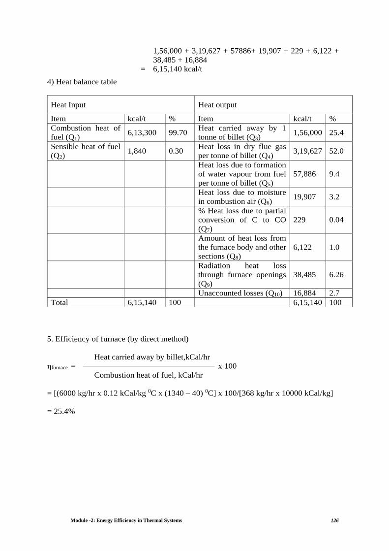
Module -2: Energy Efficiency in Thermal Systems 126
1,56,000 + 3,19,627 + 57886+ 19,907 + 229 + 6,122 +
38,485 + 16,884
= 6,15,140 kcal/t
4) Heat balance table
Heat Input Heat output
Item kcal/t % Item kcal/t %
Combustion heat of
fuel (Q1) 6,13,300 99.70
Heat carried away by 1
tonne of billet (Q3) 1,56,000 25.4
Sensible heat of fuel
(Q2) 1,840 0.30
Heat loss in dry flue gas
per tonne of billet (Q4) 3,19,627 52.0
Heat loss due to formation
of water vapour from fuel
per tonne of billet (Q5)
57,886 9.4
Heat loss due to moisture
in combustion air (Q6) 19,907 3.2
% Heat loss due to partial
conversion of C to CO
(Q7)
229 0.04
Amount of heat loss from
the furnace body and other
sections (Q8)
6,122 1.0
Radiation heat loss
through furnace openings
(Q9)
38,485 6.26
Unaccounted losses (Q10) 16,884 2.7
Total 6,15,140 100 6,15,140 100
5. Efficiency of furnace (by direct method)
Heat carried away by billet,kCal/hr
ηfurnace = x 100
Combustion heat of fuel, kCal/hr
= [(6000 kg/hr x 0.12 kCal/kg 0C x (1340 – 40) 0C] x 100/[368 kg/hr x 10000 kCal/kg]
= 25.4%

Module -2: Energy Efficiency in Thermal Systems 127
Figure 4.13: Factor for determining the equivalent of heat release from openings to the
quality of heat release from perfect black body
The instruments required for carrying out performance evaluation in a furnace is given in
the Table 4.2.
Table 4.3 Furnace Instrumentation
Sl.
No.
Measuring
Parameters
Location of
Measurement
Instrument
Required
Required
Value
1. Furnace soaking
zone temperature
(reheating furnaces)
Soaking zone
side wall
Pt/Pt-Rh
thermocouple with
indicator and
recorder
1200-1300oC
2. Flue gas Flue gas exit
from furnace and
entry to
recuperator
Chromel Alummel
Thermocouple with
indicator
700oC
max.
3. Flue gas After recuperator Hg in steel
thermometer
300oC (max)
4. Furnace hearth
pressure in the
heating zone
Near charging
end side wall
over hearth level
Low pressure ring
gauge
+0.1 mm of
Wg

Module -2: Energy Efficiency in Thermal Systems 128
5. Flue gas analyser Near charging
end side wall
Fuel efficiency
monitor for oxygen
& temperature.
O2% = 5
t = 700oC
(max)
6. Billet temperature Portable Infrared Pyrometer
or optical pyrometer
----
4.3 General Fuel Economy Measures in Furnaces
Typical energy efficiency measures for an industry with furnace are:
1. Complete combustion with minimum excess air
2. Correct heat distribution
3. Operating at the desired temperature
4. Reducing heat losses from furnace openings
5. Maintaining correct amount of furnace draught
6. Optimum capacity utilization
7. Waste heat recovery from the fluegases
8. Minimum refractorylosses
9. Use of CeramicCoatings
1. Complete Combustion with Minimum Excess Air:
The amount of heat lost in the flue gases (stack losses) depends upon amount of excess air.
In the case of a furnace carrying away flue gases at 900oC, % heat lost is shown in table
4.3.
Table 4.3: Heat Loss in Flue Gas Based on Excess Air Level
To obtain complete combustion of fuel with the minimum amount of air, it is necessary to
control air infiltration, maintain pressure of combustion air, fuel quality and excess air
monitoring.
Higher excess air will reduce flame temperature, furnace temperature and heating rate. On
the other hand, if the excess air is less, then unburnt components in flue gases will increase
and would be carried away in the flue gases through stack. The figure 4.14 also indicates
relation between air ratio and exhaust gas loss.
The optimization of combustion air is the most attractive and economical measure for
energy conservation. The impact of this measure is higher when the temperature of furnace
is high. Air ratio is the value that is given by dividing the actual air amount by the
theoretical combustion air amount, and it represents the extent of excess of air.
Excess Air % of total heat in the fuel carried away by waste
gases (flue gas temp. 900 oC)
25 48
50 55
75 63
100 71

Module -2: Energy Efficiency in Thermal Systems 129
If a reheating furnace is not equipped with an automatic air/fuel ratio controller, it is
necessary to periodically sample gas in the furnace and measure its oxygen contents by a
gas analyzer. The Figure 4.15 shows a typical example of a reheating furnace equipped
with an automatic air/fuel ratio controller.
Figure 4.14: Relation between air ratio and exhaust gas loss
Figure 4.15: Air/fuel ratio control system with flow rate controller
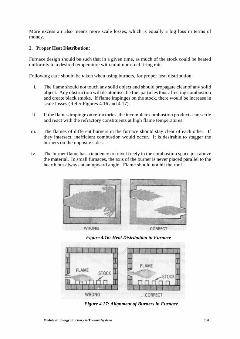
Module -2: Energy Efficiency in Thermal Systems 130
More excess air also means more scale losses, which is equally a big loss in terms of
money.
2. Proper Heat Distribution:
Furnace design should be such that in a given time, as much of the stock could be heated
uniformly to a desired temperature with minimum fuel firing rate.
Following care should be taken when using burners, for proper heat distribution:
i. The flame should not touch any solid object and should propagate clear of any solid
object. Any obstruction will de atomise the fuel particles thus affecting combustion
and create black smoke. If flame impinges on the stock, there would be increase in
scale losses (Refer Figures 4.16 and 4.17).
ii. If the flames impinge on refractories, the incomplete combustion products can settle
and react with the refractory constituents at high flame temperatures.
iii. The flames of different burners in the furnace should stay clear of each other. If
they intersect, inefficient combustion would occur. It is desirable to stagger the
burners on the opposite sides.
iv. The burner flame has a tendency to travel freely in the combustion space just above
the material. In small furnaces, the axis of the burner is never placed parallel to the
hearth but always at an upward angle. Flame should not hit the roof.
Figure 4.16: Heat Distribution in Furnace
Figure 4.17: Alignment of Burners in Furnace

Module -2: Energy Efficiency in Thermal Systems 131
v. The larger burners produce a long flame, which may be difficult to contain within
the furnace walls. More burners of less capacity give better heat distribution in the
furnace and also increase furnace life.
vi. For small furnaces, it is desirable to have a long flame with golden yellow colour
while firing furnace oil for uniform heating. The flame should not be too long that
it enters the chimney or comes out through the furnace top or through doors. In
such cases, major portion of additional fuel is carried away from the furnace.
3. Maintaining Optimum Operating Temperature of Furnace:
It is important to operate the furnace at optimum temperature. The operating temperatures
of various furnaces are given in table 4.4.
Table 4.4 Operating Temperature of Various Furnaces
Slab Reheating furnaces 1200 oC
Rolling Mill furnaces 1200 oC
Bar furnace for Sheet Mill 800 oC
Bogey type annealing furnaces 650 oC -750 oC
Operating at too high temperatures than optimum causes heat loss, excessive oxidation,
de-carbonization as well as over-stressing of the refractories. These controls are normally
left to operator judgment, which is not desirable. To avoid human error, on/off controls
should be provided.
4. Prevention of Heat Loss through Openings:
Heat loss through openings consists of the heat loss by direct radiation through openings
and the heat loss caused by combustion gas that leaks through openings.
The heat loss from an opening can also be calculated using the following formula:
HxAxaxT
xQ
4
10088.4
where,
T: absolute temperature (K)
a: factor for total radiation
A: area of opening, m2
H: time (Hr)
This is explained by an example as follows.
Example 4.3
A reheating furnace with walls 460 mm thick (X) has a billet extraction outlet, which is 1
m high (D)and 1 m wide. When the furnace temperature is 1,340°C the quantity (Q) of
radiation heat loss from this opening is evaluated as follows.

Module -2: Energy Efficiency in Thermal Systems 132
The shape of opening is square, and D/X = l/O.46 = 2.17. Thus, the factor for total
radiationis 0.71 (refer Figure 4.3) and we get,
Q=4.88x((1340+273)/100)4x0.71x1= 234,500 kcal/hr.
If the furnace pressure is slightly higher than outside air pressure (as in case of reheating
furnace) during its operation, the combustion gas inside may blow off through openings
and heat is lost with that. But damage is more, if outside air intrudes into the furnace,
making temperature distribution uneven and oxidizing billets. This heat loss is about 1%
of the total quantity of heat generated in the furnace, if furnace pressure is controlled
properly.
Control of furnace draft:
If negative pressures exist in the furnace, air infiltration is liable to occur through the cracks
and openings thereby affecting air-fuel ratio control. Tests conducted on apparently
airtight furnaces have shown air infiltration up to the extent of 40%.
Neglecting furnaces pressure could mean problems of cold metal and non-uniform metal
temperatures, which could affect subsequent operations like forging and rolling and result
in increased fuel consumption. For optimum fuel consumption, slight positive pressure
should be maintained in the furnace as shown in Figure 4.18.
Figure 4.18: Effect of pressure on the location of zero level and infiltration of air
Ex-filtration is less serious than infiltration. Some of the associated problems with ex
filtration are leaping out of flames, overheating of the furnace refractories leading to
reduced brick life, increased furnace maintenance, burning out of ducts and equipment
attached to the furnace, etc.
In addition to the proper control on furnace pressure, it is important to keep the openings
as small as possible and to seal them in order to prevent the release of high temperature
gas and intrusion of outside air through openings such as the charging inlet, extracting
outlet and peephole on furnace walls or the ceiling.
Module -2: Energy Efficiency in Thermal Systems 133
6. Optimum Capacity Utilization:
One of the most vital factors affecting efficiency is loading. There is a particular loading
at which the furnace will operate at maximum thermal efficiency. If the furnace is under
loaded a smaller fraction of the available heat in the working chamber will be taken up by
the load and therefore efficiency will be low.
The best method of loading is generally obtained by trial-noting the weight of material put
in at each charge, the time it takes to reach temperature and the amount of fuel used. Every
endeavour should be made to load a furnace at the rate associated with optimum efficiency
although it must be realised that `limitations to achieving this are sometimes imposed by
work availability or other factors beyond control.
The loading of the charge on the furnace hearth should be arranged so that,
It receives the maximum amount of radiation from the hot surfaces of the heating
chambers and the flames produced.
The hot gases are efficiently circulated around the heat receiving surfaces
Stock should not be placed in the following position
In the direct path of the burners or where impingement of flame is likely to occur.
In an area which is likely to cause a blockage or restriction of the flue system of the
furnace.
Close to any door openings where cold spots are likely to develop.
The other reason for not operating the furnace at optimum loading is the mismatching of
furnace dimension with respect to charge and production schedule.
In the interests of economy and work quality the materials comprising the load should only
remain in the furnace for the minimum time to obtain the required physical and
metallurgical requirements. When the materials attain these properties they should be
removed from the furnace to avoid damage and fuel wastage. The higher the working
temperature, higher is the loss per unit time. The effect on the materials by excessive
residence time will be an increase in surface defects due to oxidation. The rate of oxidation
is dependent upon time, temperature, as well as free oxygen content. The possible increase
in surface defects can lead to rejection of the product. It is therefore essential that
coordination between the furnace operator, production and planning personnel be
maintained.
Optimum utilization of furnace can be planned at design stage. Correct furnace for the jobs
should be selected considering whether continuous or batch type furnace would be more
suitable. For a continuous type furnace, the overall efficiency will increase with heat
recuperation from the waste gas stream. If only batch type furnace is used, careful planning
of the loads is important. Furnace should be recharged as soon as possible to enable use of
residual furnace heat.
7. Waste Heat Recovery from Furnace Flue Gases:
In any industrial furnace the products of combustion leave the furnace at a temperature
higher than the stock temperature. Sensible heat losses in the flue gases, while leaving the

Module -2: Energy Efficiency in Thermal Systems 134
chimney, carry 35 to 55 percent of the heat in put to the furnace. The higher the quantum
of excess air and flue gas temperature, the higher would be the waste heat availability.
Waste heat recovery should be considered after all other energy conservation measures
have been taken. Minimizing the generation of waste heat should be the primary objective.
Figure 4.19: Waste Heat Recovery
The sensible heat in flue gases can be generally salvaged by the following methods:
Charge preheating
Preheating of combustion air
Utilizing waste heat for other process (to generate steam or hot water by a waste
heat boiler)
Charge Pre-heating
When raw materials are preheated by exhaust gases before being placed in a heating
furnace, the amount of fuel necessary to heat them in the furnace is reduced. Since raw
materials are usually at room temperature, they can be heated sufficiently using high-
temperature gas to reduce fuel consumption rate.
Preheating of Combustion Air
For a longtime, the preheating of combustion air using heat from exhaust gas was not used
except for large boilers, metal-heating furnaces and high-temperature kilns. This method
is now being employed in compact boilers and compact industrial furnaces as well. (Refer
Figure 4.20).

Module -2: Energy Efficiency in Thermal Systems 135
A recuperator is a device that recovers heat from exhaust gas exhausted from a furnace. A
metallic recuperator has heat transfer surface made of metal, and a ceramic recuperator has
heat transfer surface made of ceramics. When the exhaust gas temperature is lower
than1,000°C and air for combustion is preheated, a metallic recuperator is used in general.
Figure 4.20: Preheating the air for combustion by a recuperator
External Recuperators
There are two main types of external recuperators:
✓ radiation recuperators;
✓ convection recuperators
Radiation recuperators generally take the form of concentric cylinders, in which the
combustion air passes through the annulus and the exhaust gases from the furnace pass
through the centre, see Figure 4.21 (a). The simple construction means that such
recuperators are suitable for use with dirty gases, have a negligible resistance to flow, and
can replace the flue or chimney if space is limited. The annulus can be replaced by a ring
of vertical tubes, but this design is more difficult to install and maintain. Radiation
recuperators rely on radiation from high temperature exhaust gases and should not he
employed with exhaust gases at less than about 800°C.
Convection recuperators consist essentially of bundles of drawn or cast tubes; see Figure
4.21 (b). Internal and/or external fins can be added to assist heat transfer. The combustion
air normally passes through the tubes and the exhaust gases outside the tubes, but there are
some applications where this is reversed. For example, with dirty gases, it is easier to keep
the tubes clean if the air flows on the outside. Design variations include 'IP tube and double
pass systems. Convection recuperators are more suitable for exhaust gas temperatures of
less than about 900°C.

Module -2: Energy Efficiency in Thermal Systems 136
Figure 4.21: Metallic Recuperators
Self-Recuperative Burners
Self-recuperative burners (SRBs) are based on traditional heat recovery techniques in that
the products of combustion are drawn through a concentric tube recuperator around the
burner body and used to pre-heat the combustion air (Figure 4.22)
Figure 4.22: Self-Recuperative Burners

Module -2: Energy Efficiency in Thermal Systems 137
A major advantage of this type of system is that it can be retro-fitted to an existing furnace
structure to increase production capability without having to alter the existing exhaust gas
ducting arrangements. SRBs are generally more suited to heat treatment furnaces where
exhaust gas temperatures are lower and there are no stock recuperation facilities.
Estimation of fuel savings
By using preheated air for combustion, fuel can be saved. The fuel saving rate is given by
the following formula:
(%)100xQPF
PS
Where,
S: Fuel saving rate
F: Calorific value of fuel (kcal/kgfuel)
P: Quantity of heat brought in by preheated air (kcal/kgfuel)
Q: Quantity of heat taken away by exhaust gas (kcal/kgfuel)
By this formula, fuel saving rates for heavy oil and natural gas were calculated for various
temperatures of exhaust gas and preheated air. The results are shown in the following
Figure 4.23 and Figure 4.24.
Figure 4.23: Fuel conservation rate when oil is used

Module -2: Energy Efficiency in Thermal Systems 138
Figure 4.24: Fuel conservation rate when natural gas is used
For example, when combustion air for heavy oil is preheated to 400°C by a heat exchanger
with an inlet temperature of 800°C, the fuel conservation rate is estimated to be about 20
percent. When installing a recuperator in a continuous steel reheating furnace, it is
important to choose a preheated air temperature that will balance the fuel saving effect and
the invested cost for the equipment.
Also, the following points should be checked:
Draft of exhaust gas: When exhaust gas goes through a recuperator, its draft
resistance usually causes a pressure loss of 5-10 mm H2O. Thus, the draft of stack
should be checked.
Air blower for combustion air: While the air for combustion goes through a
recuperator, usually 100-200 mm H2O pressure is lost. Thus, the discharge pressure
of air blower should be checked, and the necessary pressure should be provided by
burners.
Since the volume of air is increased owing to its preheating, it is necessary to be careful
about the modification of air-duct diameters and blowers. As for the use of combustion
gases resulting from high-density oils with a high sulphur content, care must be taken to
avoid problems such as clogging with dust or sulphides, corrosion or increases in nitrogen
oxides.
Table 4.5 gives details of various air preheaters. In addition, heat-pipe-type heat
exchangers and high temperature gas or gas-plate heat exchangers can serve as air
preheaters.

Module -2: Energy Efficiency in Thermal Systems 139
Table 4.5: Details of air preheaters
Type Exhaust Gas
Temperature, 0C
Preheated Air
Temperature,0C
Object Furnace R
ecupera
tive
Meta
llic
recupera
tor
Flu
e
inst
all
ati
on
Convective:
multitubular,
other
1000 or below 300 – 600
Heating furnace,
heat treatment
furnace and other
industrial furnaces
Chim
ney
inst
all
ati
on
Radiative and
convective 1000 – 1300 -do- -do-
Ceramic (tile)
recuperator 1200 – 1400 400 – 700
Soaking pit and
glass
Regenera
tive General 1000 – 1600 600 – 1300
Coke oven, hot
blast stove & glass
kiln
Rotary regenerative 600 100 - 300 Boiler, hot blast
stove
Utilizing Waste Heat as a Heat Source for Other Processes
The temperature of heating-furnace exhaust gas can be as high as 400 –600°C, even after
heath as been recovered from it.
When a large amount of steam or hot water is needed in a plant, installing a waste heat
boiler to produce the steam or hot water using the exhaust gas heat is preferred. If the
exhaust gas heat is suitable for equipment in terms of heat quantity, temperature range,
operation time etc., the fuel consumption can be greatly reduced. In one case, exhaust gas
from a quenching furnace was used as a heat source in a tempering furnace so as to obviate
the need to use fuel for the tempering furnace itself.
8. Minimizing Wall Losses
About 30-40% of the fuel input to the furnace generally goes to makeup for heat losses in
intermittent or continuous furnaces. The appropriate choice of refractory and insulation
materials goes along way in achieving fairly high fuel savings in industrial furnaces.
The heat losses from furnace walls affect the fuel economy considerably. The extent of
wall losses depends on:
Emissivity of wall
Thermal conductivity of refractories
Wall thickness
Whether furnace is operated continuously or intermittently

Module -2: Energy Efficiency in Thermal Systems 140
Heat losses can be reduced by increasing the wall thickness, or through the application of
insulating bricks. Outside wall temperatures and heat losses of a composite wall of a
certain thickness of fire brick and insulation brick are much lower, due to lesser
conductivity of insulating brick as compared to a refractory brick of similar thickness. In
the actual operation in most of the small furnaces the operating periods alternate with the
idle periods. During the off period, the heat stored in the refractories during the on period
is gradually dissipated, mainly through radiation and convection from the cold face. In
addition, some heat is abstracted by air flowing through the furnace. Dissipation of stored
heat is a loss, because the lost heat is again imparted to the refractories during the heat
“on” period, thus consuming extra fuel to generate that heat. If a furnace is operated 24
hours, every third day, practically all the heat stored in the refractories is lost. But if the
furnace is operated 8 hours per day all the heat stored in the refractories is not dissipated.
For a furnace with a fire brick wall of 350mm thickness, it is estimated that 55percent of
the heats to red in the refractories is dissipated from the cold surface during the 16 hours
idle period. Furnace walls built of insulating refractories and cased in a shell reduce the
flow of heat to the surroundings.
Prevention of Radiation Heat Loss from Surface of Furnace
The quantity of heat release from surface of furnace body is the sum of natural convection
and thermal radiation. This quantity can be calculated from surface temperatures of
furnace. The temperatures on furnace surface should be measured at as many points as
possible, and their average should be used. If the number of measuring points is too small,
the error becomes large.
The quantity (Q)of heat release from are heating furnace is calculated with the following
formula:
4
2
4
14/521
100
273t
100
273txE88.4)tt(xaQ
Where,
Q : Quantity of heat released (kcal/hr/m2)
a : Factor regarding direction of the surface of natural convection ceiling = 2.8,
side walls = 2.2, hearth = 1.5
tl : Temperature of external wall surface of the furnace (°C)
t2 : Temperature of air around the furnace (°C)
E : Emissivity of external wall surface of the furnace
The first term of the formula above represents the quantity of heat release by natural
convection, and the second term represents the quantity of heat release by radiation. The
following Figure 4.25 shows the relation between the temperature of external wall surface
and the quantity of heat release calculated with this formula.

Module -2: Energy Efficiency in Thermal Systems 141
Figure 4.25: Quantity of heat release at various temperature
This is explained with an example as follows:
Example 4.4
There is a reheating furnace whose ceiling, side walls and hearth has 20 m2, 50 m2, and 20
m2 of surface area respectively. Their surface temperatures are measured and the averages
are 80oC, 90oC and 100oC respectively. Evaluate the quantity of heat release from the
whole surface of the furnace.
From the above figure 4.25, the quantities of heat release from ceiling, side walls and
hearth per unit area are respectively 650 kcal/m2h, 720 kcal/m2h, and 730 kcal/m2h.
Therefore, the total quantity of heat release is,
Q = (650x20) + (720x50) + (730x20) = 13000 + 36000 +14600= 63,600kcal/hr.
Use of Ceramic Fibre
Ceramic fibre is a low thermal mass refractory used in the hot face of the furnace and
fastened to the refractory walls. Due to its low thermal mass the storage losses are
minimized. This results in faster heating up of furnace and also faster cooling. Energy
savings by this application is possible only in intermittent furnaces.
9. Use of Ceramic Coatings
Ceramic coatings in furnace chamber promote rapid and efficient transfer of heat, uniform
heating and extended life of refractories. The emissivity of conventional refractories
decreases with increase in temperature whereas for ceramic coatings it increases. This
outstanding property has been exploited for use in hot face insulation.

Module -2: Energy Efficiency in Thermal Systems 142
Ceramic coatings are high emissivity coatings which when applied has a long life at
temperatures up to 1350oC. The coatings fall into two general categories-those used for
coating metal substrates, and those used for coating refractory substrates. The coatings are
non-toxic, non-flammable and water based. Applied at room temperatures, they are
sprayed and air dried in less than five minutes. The coatings allow the substrate to maintain
its designed metallurgical properties and mechanical strength. Installation is quick and
can be completed during shut down. Energy savings of the order of 8-20% have been
reported depending on the type of furnace and operating conditions.
Fish Bone Diagram for Energy Conservation Analysis in Furnaces
All the possible measures discussed can be incorporated in furnace design and operation.
The figure 4.26 shows characteristics diagram of energy conservation for a fuel-fired
furnace.
Figure 4.26 Characteristic Diagram of Energy Conservation for Reheating Furnace
Case Study 4.1
In are rolling mill, following energy conservation measures have been implemented and
savings achieved are explained below:
Saving by Installing a Recuperator
This plant had a continuous pusher type billet reheating furnace. The furnace consists of
two burners at the heating zone. The furnace is having a length of 40 ft. Annual furnace
oil consumption is 620 KL. The furnace did not have any waste heat recovery device. The
flue gas temperature is found to be 650 0C. To tap this potential heat, the unit has installed
a recuperator device. It was possible to preheat the combustion air to 325 0C. By resorting
to this measure, there was 15% fuel saving which is 93 KL of oil per annum.

Module -2: Energy Efficiency in Thermal Systems 143
Judicious Use of Combustion Equipment in two Zone Furnaces
During start up the furnace is already filled up with billets of previous day and has a
temperature of about 700oC. During initial starting of furnace only the billets in the
soaking zone are heated up as there is no movement of billets. Further the flow of heat is
from soaking zone to heating zone. Therefore, during starting the soaking zone burners are
switched on first and heating zone burners are started only after the mill starts operating.
Similarly, prior to mill stoppage billets lying in soaking zone have already attained re-
rolling temperature and the incoming billets from heating zone will not be rolled and hence
there is no need to heat those billets. As a result the burners in heating zone are stopped at
least 30 to 60 minutes before the stoppage of mill.
The company has saved about 32.4 kL of furnace oil per annum.
Calculations:
a. During Starting:
Savings by operating 2 nos. of LAP 4 A Wesman burners
30 minutes after starting up = 54 litres
b. During Shutdown:
Savings by switching off 2 Nos. of LAP Wesman burners
Before 30 minutes of furnace shut down = 54 litres
Total savings per day = 108 litres
Annual Savings = 32.4 KL
Example 4.5
Calculate the induction melting furnace efficiency from the following melt cycle data
Mild steel (MS) scrap charged : 1500 kg
Specific heat of MS : 0.682 kJ/kg 0C
Latent heat of MS : 272 kJ/kg
MS melting temperature : 1650 0C
Inlet MS charge temperature : 40 0C
Electricity consumed during cycle : 1020 kWh
Solution Theoretical energy required for melting = 1500 (0.682 x (1650 – 40) + 272)/3600 kWh
= 570.8 kWh
Actual input = 1020 kWh
Furnace efficiency = 570.8 x 100 / 1020
= 56%

Module -2: Energy Efficiency in Thermal Systems 144
Problem 4.6
In a crude distillation unit of a refinery, furnace is operated to heat 500 m3/hr of crude oil
from 255°C to 360°C by firing 3.4 tons/hr of fuel oil having GCV of 9850 kcal/kg. As an
energy conservation measure, the management has installed an air pre heater (APH) to
reduce the flue gas heat loss. The APH is designed to pre-heat 57 tonnes/hr of combustion
air to 195°C.
Calculate the efficiency of the furnace before & after the installation of APH.
Consider the following data:
Specific heat of crude oil = 0.6 kcal/kg°C
Specific heat of air = 0.24 kcal/kg°C
Specific gravity of Crude oil = 0.85
Ambient temperature = 28°C.
Solution Before the installation of APH
Heat gain by the crude = 500 x 1000 x 0.85 x 0.6 x (360-255)
= 26775000 kCal/hr
Heat input to the furnace = 3.4 x1000x 9850
= 33490000 kCal/hr
Efficiency of the furnace = 26775000 / 33490000
= 80 %
After the installation of APH
Heat gain by the crude = 500 x 1000 x 0.85 x 0.6 x (360-255)
= 26775000 kCal/hr
Heat gain by Air-preheater = 57 x 1000 x 0.24 x (195-28)
= 2284560 kCal/hr
Heat reduction in the furnace input = Heat gain by Air-preheater
New Heat input to the furnace = 33490000 – 2284560
= 31,205,440 kCal/hr
Efficiency of furnace after installation of APH = 26775000 / 31,205,440
= 85.8 %

Module -2: Energy Efficiency in Thermal Systems 145
Chapter 5: Insulation and Refractories
5.1 Insulation
5.1.1 Purpose of Insulation
Insulation is used to prevent heat loss or heat gain to enable less energy consumption while
meeting the demands of heating and cooling. A thermal insulator is a poor conductor of
heat and has a low thermal conductivity and hence is used in buildings and in
manufacturing processes to prevent heat loss or heat gain. Thermal insulation delivers the
following benefits:
Reduces over-all energy consumption
Offers better process control by maintaining process temperature.
Prevents corrosion by keeping the exposed surface of a refrigerated system above
dew point
Provides fire protection to equipment
Absorbs vibration
Insulating materials are porous, containing large number of dormant air cells. Insulation
for heating system should be fire proof, be vermin proof, have lasting quality, be
mechanically strong, be compact and be light in weight.
5.1.2 Types and Application
The Insulation can be classified into three groups according to the temperature ranges for
which they are used. They are
Low Temperature Insulations (up to 90°C)
This range covers insulating materials for refrigerators, cold and hot water systems, storage
tanks, etc. The commonly used materials are Cork, Wood, 85% magnesia, Mineral Fibers,
Polyurethane and expanded Polystyrene, etc
Medium Temperature Insulations (90 - 325°C)
Insulators in this range are used in low temperature, heating and steam raising equipment,
steam lines, flue ducts etc. The types of materials used in this temperatures range include
85% Magnesia, Asbestos, Calcium Silicate and Mineral Fibers etc.
High Temperature Insulations (325° C - above)
Typical uses of such materials are super-heated steam system, oven dryer and furnaces etc.
The most extensively used materials in this range are Asbestos, Calcium Silicate, Mineral
Fibre, Mica and Vermiculite based insulation, Fireclay or Silica based insulation and
Ceramic Fibre.
The Table 5.1 describes the characteristics and applications of various insulating materials.

Module -2: Energy Efficiency in Thermal Systems 146
Table 5.1: Characteristics & Applications of various insulating materials
S. No. Type of Insulation Application Characteristics
1 Polystyrene
An organic form made
by polymerizing styrene
Suitable for low
temperatures (-167 °C to
82 °C).
Mainly used in
Cool rooms,
refrigeration piping
and
concrete retaining
structures
Rigid and light weight.
Combustible, has a low
melting point, is UV
degradable, and
susceptible to attacks by
solvents
2 Polyurethane
Made by reacting
isocyanates and
alcohols. Made in
continuous slab or
foamed in situ.
Suitable for low
temperatures (-178°C to
4 °C). Mainly used in
cool rooms,
refrigerated
transports,
deep freezing
cabinets,
refrigeration piping,
floor and foundation
insulation.
Closed cell structure,
low density and high
mechanical strength
Combustible, produces
toxic vapours and has a
tendency to smoulder.
3 Rockwool (mineral
fibre)
Manufactured by
melting basalt and coke
in a cupola at about 1500
°C. Phenolic binders
used.
Suitable for
temperatures up to
820 °C.
Mainly used to insulate
industrial ovens,
heat exchangers,
driers,
boilers and high
temperature pipes
Has a wide density range
and is available in matts,
blankets, loose form or
preformed for pipe
insulation.
It is chemically inert,
non- corrosive and
maintains Mechanical
strength during handling
4 Fibre Glass
Formed by bonding long
glass fibres with a
thermo setting resin to
form blankets and batts,
semi-rigid boards, high
density rigid boards and
preformed pipe sections
Suitable for
temperatures up to
540 °C.
Mainly used to insulate
industrial ovens,
heat exchangers,
driers,
boilers and pipe works
Will not settle or
disintegrate with ageing.
Fibre glass products are
slightly alkaline pH9
(neutral is pH7). It
should not promote or
accelerate the corrosion
of steel. Hence, it is
protected from external
contamination.
5 Calcium Silicate
Made from anhydrous
calcium silicate material
reinforced with a non-
asbestos binder.
Available in slab form of
various sizes.
Suitable for
temperatures up to 1050
°C.
Mainly used to
insulate furnace
walls,
fire boxes,
back-up refractory,
Has a minute air cell
structure, has a low
thermal conductivity
and will retain its size
and shape in its useable
temperature range.
It is light weight, but has
good structural strength

Module -2: Energy Efficiency in Thermal Systems 147
Classification of insulating materials based on their forms
Powdered: It is mixed with water used to cover odd shapes such as pipe unions,
elbows, valves etc.
Sheet: applied to flat areas such as ceilings, ducts, etc.
Block and brick: used to cover outside surfaces of boilers.
Blanket: used to cover ducts, pipes.
Tube: used to insulate steam and hot water pipes.
Roll: used to cover cold and warm-air ducts for furnace castings in hot-air heating
systems.
Custom Moulded Insulation: Lagging materials can be obtained in bulk, in the
form of moulded sections; semi - cylindrical for pipes, slabs for vessels, flanges,
valves etc. The main advantage of the moulded sections is the ease of application
and replacement when undertaking repairs for damaged lagging.
5.1.3 Thermal Resistance (R)
The effectiveness of insulation is measured in terms of thermal resistance, called
R-value, which indicates the resistance of heat flow. The higher the R-value, the greater
the insulating power. The actual R-value of thermal insulation depends on the type of
material, its thickness and density. In calculating the R-value of insulation, the R-values
of the individual layers are added. The amount of insulation depends on:
Climate
Type of fuel used
The section the requires insulation
flue lining and
boilers
so it can withstand
mechanical abrasion. It
will not burn or rot, is
moisture resistant and
non-corrosive.
6 Ceramic Fibre
Made from high purity
alumina and silica
grains, melted in an
electric furnace and
blasted by high velocity
gases into light fluffy
fibres. Made in a variety
of forms
Suitable for
temperatures up to 1430
°C.
Mainly used to insulate
furnace and kiln
back-up refractory,
fire boxes,
glass feeder bowls,
furnace repair,
induction
coil insulation,
high temperature
gaskets and
wrapping material
Suitable for many
applications because of
the variety of forms.
These include cloth, felt,
tape, coating cements
and variform castable
(fire brick)
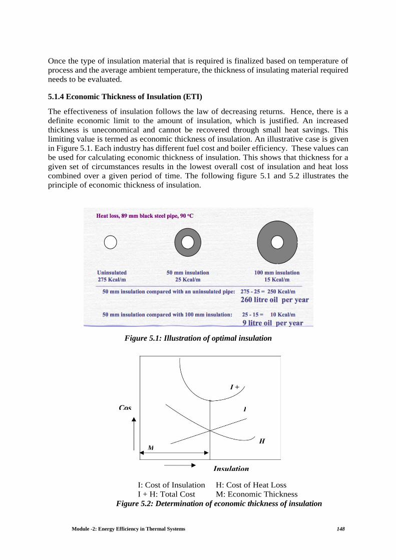
Module -2: Energy Efficiency in Thermal Systems 148
Once the type of insulation material that is required is finalized based on temperature of
process and the average ambient temperature, the thickness of insulating material required
needs to be evaluated.
5.1.4 Economic Thickness of Insulation (ETI)
The effectiveness of insulation follows the law of decreasing returns. Hence, there is a
definite economic limit to the amount of insulation, which is justified. An increased
thickness is uneconomical and cannot be recovered through small heat savings. This
limiting value is termed as economic thickness of insulation. An illustrative case is given
in Figure 5.1. Each industry has different fuel cost and boiler efficiency. These values can
be used for calculating economic thickness of insulation. This shows that thickness for a
given set of circumstances results in the lowest overall cost of insulation and heat loss
combined over a given period of time. The following figure 5.1 and 5.2 illustrates the
principle of economic thickness of insulation.
Figure 5.1: Illustration of optimal insulation
I: Cost of Insulation H: Cost of Heat Loss
I + H: Total Cost M: Economic Thickness
Figure 5.2: Determination of economic thickness of insulation
Cos

Module -2: Energy Efficiency in Thermal Systems 149
Heat loss from a surface is expressed as
H = h × A × (Th − Ta) Where,
h is Heat transfer coefficient, W/m2 K (2000 W/ m2 K)
H is Heat loss, Watts
Ta is Average ambient temperature, ºC
Th is Hot surface temperature (for hot fluid piping) in ºC & Cold surface temperature
(for cold fluids piping) in ºC
The point where the amount of insulation gives the greatest return on investment is called
as “economic thickness of insulation (ETI)”. The determination of economic thickness
requires the attention to the following factors.
Cost of fuel
Annual hours of operation
Heat content of fuel
Boiler efficiency
Operating surface temperature
Pipe diameter/thickness of surface
Estimated cost of insulation.
Average exposure ambient still air temperature.
The cost of insulation depends not only on the thickness of insulating material but also on
the material itself. Materials with higher thermal resistance will require insulating material
of less thickness compared to insulating material with lower thermal resistance. At the
same time cost of higher thermal resistance for same thickness may be higher compare to
insulating material with lower thermal resistance.
5.1.5 Heat Savings and Application Criteria
Various charts, graphs and references are available for heat loss computation. The surface
heat loss can be computed with the help of a simple relation as given below. This equation
can be used up to 200 °C surface temperature. Factors like wind velocities, conductivity
of insulating material etc. has not been considered in the equation.
𝑆 = [10 +𝑇𝑠 − 𝑇𝑎
20] (𝑇𝑠 − 𝑇𝑎)
Where
S =Surface heat loss in Kcal/hr m2
Ts =Hot surface temperature in °C
Ta =Ambient temperature in °C
𝑇𝑜𝑡𝑎𝑙 ℎ𝑒𝑎𝑡 𝑙𝑜𝑠𝑠/ℎ𝑟 (𝐻𝑠) = 𝑆 × 𝐴 Where,
A = Surface area inm2

Module -2: Energy Efficiency in Thermal Systems 150
Based on the cost of heat energy, the quantification of heat loss in BDT can be worked out
as under:
Equivalent fuel loss (Hf) (kg
yr) =
Hs × Yearly hours of operation
GCV × ηb
Annual heat loss in monetary terms (BDT) = Hf × Fuel cost (BDT/kg)
Where
GCV = Gross Calorific value of fuel Kcal/Kg
ηb= Boiler efficiency in %
Example 5.1
Consider a 50m pipe of 150 mm outer diameter carrying process fluid at 150°C. The
ambient temperature is 20 °C. The heat is supplied by boiler operating at 80% efficiency
and the cost of fuel which is HSD with GCV of 10000 Kcal/ lit is BDT 50/liter. It is
considered to insulate this pipe with semi-cylindrical pre-fabricated glass mineral fibre
with a life of 5 years. The cost of glass mineral fiber of various thickness and the surface
temperature achievable after insulation for calculation purpose is given below.
Thickness, mm Cost, BDT/m Surface Temperature. after insulation, °C
25 500 65
50 600 48
75 750 43
100 900 40
Calculate fuel saved by using above thickness levels of insulation. Draw a graph of Costs
of insulation vs thickness and identify the economic thickness of insulation required.
Methodology:
Step 1: Calculate the surface area of pipe
Step 2: Calculate unit heat loss and using surface area calculate total surface heat
loss with and without insulation.
Step 3: Convert heat loss to fuel loss using calorific value of fuel used in boiler.
Adjust fuel usage to boiler efficiency. Convert hourly loss to yearly loss.
Step 4: Using unit fuel cost data estimate fuel loss in cost terms for the entire life
of insulating material i.e. 5 years.
Step 5: Using given insulating material costs estimate cost of insulation for varying
thickness of the insulating material.
Step 6: Calculate the total cost of insulation and fuel loss cost.
Step 7: Plot graph of Insulation thickness v/s Cost of insulating material, Cost of
fuel loss and total cost.
Step 8: Identify the economic thickness of insulating material by drawing a vertical
line at the point of intersection of cost of insulating material and cost of fuel loss
lines.

Module -2: Energy Efficiency in Thermal Systems 151
Economic thickness of insulation for 150 mm dia pipe
Step 1
Unit
Insulation Thickness mm 25 50 75 100
Length of pipe, l m 50
Bare pipe outer diameter, d mm 150
𝑺𝒖𝒓𝒇𝒂𝒄𝒆 𝑨𝒓𝒆𝒂 = 𝝅 × 𝒅 × 𝒍
Bare pipe surface area m2 23.56 23.56 23.56 23.56
Step 2
Ambient Temperature °C 20
Surface Temperature
-before insulation °C 150
-after insulation °C 65 48 43 40
Surface heat loss 𝑆 = [10 +
𝑇𝑠 − 𝑇𝑎
20] (𝑇𝑠 − 𝑇𝑎)
-without insulation
Kcal/hr.m2 2145
-after insulation
Kcal/hr.m2 551.25 319.2 256.45 220
Heat loss reduction
Kcal/hr.m2 1594 1826 1888 1925
Step 3
Total energy saved (Hs) Kcal/year 13387500 15336720 15863820 16170000
Yearly hours of operation hrs 8400
GCV Kcal/Lit 10000
Boiler Efficiency % 80
𝐸𝑞𝑢𝑖𝑣𝑎𝑙𝑒𝑛𝑡 𝑓𝑢𝑒𝑙 𝑙𝑜𝑠𝑠 (𝐻𝑓) (𝐿𝑖𝑡
𝑦𝑟) =
𝐻𝑠 × 𝑌𝑒𝑎𝑟𝑙𝑦 ℎ𝑜𝑢𝑟𝑠 𝑜𝑓 𝑜𝑝𝑒𝑟𝑎𝑡𝑖𝑜𝑛
𝐺𝐶𝑉 × 𝜂𝑏
Total fuel energy lost per
year Lit/year 370 215 172 148
𝑭𝒖𝒆𝒍 𝑺𝒂𝒗𝒊𝒏𝒈 = 𝑭𝒖𝒆𝒍 𝑳𝒐𝒔𝒔 𝒘𝒊𝒕𝒉𝒐𝒖𝒕 𝒊𝒏𝒔𝒖𝒍𝒂𝒕𝒊𝒐𝒏 − 𝑭𝒖𝒆𝒍 𝒍𝒐𝒔𝒔 𝒘𝒊𝒕𝒉 𝒊𝒏𝒔𝒖𝒍𝒂𝒕𝒊𝒐𝒏
Yearly fuel savings Lit/year 1071 1227 1269 1294
Step 4
𝐿𝑖𝑓𝑒 𝑐𝑦𝑐𝑙𝑒 ℎ𝑒𝑎𝑡 𝑙𝑜𝑠𝑠 𝑖𝑛 𝑚𝑜𝑛𝑒𝑡𝑎𝑟𝑦 𝑡𝑒𝑟𝑚𝑠 (𝐵𝐷𝑇)= 𝐻𝑓 × 𝐿𝑖𝑓𝑒 𝑜𝑓 𝑖𝑛𝑠𝑢𝑙𝑎𝑡𝑖𝑜𝑛 × 𝐹𝑢𝑒𝑙 𝑐𝑜𝑠𝑡 (𝐵𝐷𝑇/𝑙𝑖𝑡)
Fuel Cost BDT/Lit 50
Cost of fuel loss
-without insulation BDT/5 yrs 360360
-with insulation [H] BDT/ 5yrs 92610 53626 43084 36960
Step 5
Cost of insulation BDT/m 450 600 750 900
Total cost of insulation [I] BDT 22500 30000 37500 45000
Step 6
Total Cost (insulation &
fuel loss) [I+H]
BDT 115110 83626 80584 81960

Module -2: Energy Efficiency in Thermal Systems 152
Step 7:
Step 8: From the above graph it can be seen that economic thickness of insulation is 80mm.
5.1.6 Cold Insulation
Cold Insulation Features
Cold Insulation should be considered and where operating temperature are below ambient
where protection is required against heat gain, condensation or freezing. Condensation will
occur whenever moist air comes into contact with the surface that is at a temperature lower
than the due point of the vapour. In addition, heat gained by uninsulated chilled water lines
can adversely affect the efficiency of the cooling system. The most important
characteristics of a suitable Cold insulation material have following features:
Low thermal conductivity
High water resistance, and
Durability at low temperature
Other properties like easy workability, negligible capillary absorption should also be taken
into consideration while making a selection. The insulation system is only as good as its
vapour barrier and the care with which it is installed.
Material Selection for Cold Insulation
Selection of insulation materials should be carefully considered where the possibility of
steam purging of the equipment is required or for other reasons which may cause the
temperature to be increased to a level that exceeds the maximum limiting temperature of
the insulation materials, i.e., material then deteriorate. Examples of cold insulation include
Urethane Foam, Expanded Polystyrene, Resin bonded glass wool, Resin Bonded Glass
wool, and Phenolic Foam.
Economics of Cold Insulation:
Unlike hot insulation system, the concern area in Cold Insulation is the heat gain into the
refrigerated space, which leads to increase in the refrigeration load (TR) & energy
consumption as a consequence. The cost of heat gain can thus be assessed & evaluated
0
20
40
60
80
100
120
25 50 75 100
Co
st, B
DT
Tho
usa
nd
s
Insulation Thickness, mm
Economic Thickness of InsulationI H I+H

Module -2: Energy Efficiency in Thermal Systems 153
against cost of additional cold insulation thickness, to optimize overall energy
consumption & cost in refrigeration system.
5.2 Refractories
Refractories are non-metallic materials have insulating and other chemical and physical
properties that make them able to contain the heat generated by burning of the fuel in the
furnace and to minimise heat losses, withstand high temperatures and make them
applicable for structures, or as components of systems, that are exposed to environments
above 1,000 °F (811 K; 538 °C) and should not contaminate the material with which it is
in contact. Refractory materials are used in furnaces, kilns, incinerators, and reactors.
The various combinations of operating conditions under which refractories are used, make
it necessary to manufacture a range of refractory materials with different properties and
accordingly are made in varying combinations and shapes for different applications. A
furnace designer should have a clear idea of the service conditions of different refractory
and for which the refractory is being used and needs to consider the following points,
before selecting a refractory.
Area of application
Working temperatures
Extent of abrasion and impact
Structural load of the furnace
Stress due to temperature gradient in the structures and temperatures fluctuations
Chemical compatibility with the furnace environment
Heat transfer and fuel conservation
Cost consideration
Properties of Refractories
Some of the important properties of refractories are:
Size: The size and shape of the refractories is a part of the design feature. It is an important
feature in design since it affects the stability of any structure. Accuracy and size is
extremely important to enable proper fitting of the refractory shape and to minimize the
thickness and joints in construction.
Bulk density: A useful property of refractories is bulk density, which defines the material
present in a given volume. An increase in bulk density of a given refractory increases its
volume stability, its heat capacity, as well as resistance to slag penetration.
Porosity: The apparent porosity is a measure of the volume of the open pores, into which
a liquid can penetrate, as a percentage of the total volume. This is an important property
in cases where the refractory is in contact with molten charge and slags. A low apparent
porosity is desirable since it would prevent easy penetration of the refractory size and
continuity of pores will have important influences on refractory behaviour. A large number
of small pores is generally preferable to an equivalent number of large pores. Cold crushing
strength: The cold crushing strength, which is considered by some to be of doubtful
relevance as a useful property, other than that it reveals little more than the ability to
withstand the rigors of transport, can be used as a useful indicator to the adequacy of firing

Module -2: Energy Efficiency in Thermal Systems 154
and abrasion resistance in consonance with other properties such as bulk density and
porosity.
Pyrometric cone equivalent (PCE): Temperature at which a refractory will deform under
its own weight is known as its softening temperature which is indicated by PCE.
Refractories, due to their chemical complexity, melt progressively over a range of
temperature. Hence refractoriness or fusion point is ideally assessed by the cone fusion
method. The equivalent standard cone which melts to the same extent as the test cone is
known as the pyrometric cone equivalent.
Figure 5.3: Pirometric Cones
Thus in the Figure 5.3 refractoriness of Sample A is much higher than B and C. The
pyrometric cone equivalent indicates only the softening temperature. But, in service the
refractory is subjected to loads which would deform the refrectory at a much lower
temperature than that indicated by PCE. With change in the environmental conditions,
such as reducing atmosphere, the P.C.E. value changes drastically.
Refractoriness under load (RUL): The refractoriness under load test (RUL test) gives an
indication of the temperature at which the bricks will collapse, in service conditions with
similar load.
Creep at high temperature: Creep is a time dependent property which determines the
deformation in a given time and at a given temperature by a material under stress.
Volume stability, expansion, and shrinkage at high temperatures: The contraction or
expansion of the refractories can take place during service. Such permanent changes in
dimensions may be due to several operational factors.
Reversible thermal expansion: Any material when heated, expands, and contracts on
cooling. The reversible thermal expansion is a reflection on the phase transformations that
occur during heating and cooling.
Thermal conductivity: Thermal conductivity depends upon the chemical and mineralogical
compositions as well as the glassy phase contained in the refractory and the application
temperature. The conductivity usually changes with rise in temperature. In cases where
heat transfer is required though the brick work, for example in recuperators, regenerators,

Module -2: Energy Efficiency in Thermal Systems 155
muffles, etc. the refractory should have high conductivity. Low thermal conductivity is
desirable for conservation of heat by providing adequate insulation.
The provisions for back-up insulation, conserves heat but at the same time it increases the
hot face temperature and hence the demand on the refractory quality increases.
Light weight refractories of low thermal conductivity find wider applications in the
moderately low temperature heat treatment furnaces, where its primary function is usually
conservation of energy. It is more so in case of batch type furnaces where the low heat
capacity of the refractory structure would minimize the heat storage during the intermittent
heating and cooling cycles.
5.2.1 Selection of Refractories
The selection of refractories for any particular application is made with a view to achieve
the best performance of the equipment furnace, kiln or boiler and depends on their
properties. Further, the choice of a refractory material for a given application will be
determined by the type of furnace or heating unit and the prevailing conditions e.g. the
gaseous atmosphere, the presence of slags, the type metal charges etc. It is, therefore, clear
that temperature is by no means the only criterion for selection of refractories. Important
physical properties of some insulating refractories that are considered in selecting them
are shown in the following Table 5.2.
Table 5.2: Physical properties of some insulating refractories
Type/grade
Thermal
Conductivity at
400 °C
Max. safe
Temp °C
Cold Crushing
Strength
Kg/cm2
Porosity %
Bulk
Density
Kg/m2
Diatomite
Solid 0.025 1000 270 52 1090
Diatomite
Porous 0.014 800 110 77 540
Clay 0.030 1500 260 68 560
High Alumina 0.028 1500-1600 300 66 910
Silica 0.040 1400 400 65 830
Besides the physical properties chemical properties and the working atmosphere where
these are used also influence their selection. Considering these factors refractories are
classified based on the refractory constituents, behavior of the refractory constituents in
their working atmosphere, and the form of refractory application
5.2.2 Classification of Refractories
Refractories are classified based on their refractoriness, based on chemical composition of
refractories, their form and operating temperatures.
Classification based on refractoriness
Based on the property of refractoriness, they are usually classified into four classes using
their PCE1 (pyro metric cone equivalent) value as given in table 5.3.

Module -2: Energy Efficiency in Thermal Systems 156
Table 5.3: Classification of Refractories based on PCE Value
Class of Refractory PCE value
Super duty refractories 33 - 38
High duty refractories 30 - 33
Intermediate duty refractories 28 - 30
Low duty refractories 19 - 28
Classification based on composition of Refractories
Refractories can be classified on the basis of chemical composition and method of
manufacture. The constituents, characteristics and applications of these refractories are
summarized in table 5.4.
Table 5.4: Classification of Refractories based on Materials, their characteristics and
applications
Refractory Type General Characteristics Application
Acid Bricks: Used in areas where both slag and atmosphere are acidic and are attacked by
alkalis (basic slags).
Silica High strength at high temperatures,
residual expansion, low specific gravity,
high expansion coefficient at low
temperatures, low expansion coefficient
at high temperatures
Glass tank crown, copper
refining furnace, electric arc
furnace roof
Fused silica Low thermal expansion coefficient, high
thermal shock resistance, low thermal
conductivity, low specific gravity, low
specific heat
Coke over, hot stove, soaking
pit, glass tank crown
Fireclay
(Chamottee)
Consists of kaolinite (Al2O3.2SiO2.2H2O)
and minor amounts of other clay
materials. Low thermal expansion
coefficient. Low thermal conductivity,
low specific gravity, low specific heat,
low strength at high temperatures, less
slag penetration
Ladle, runner, sleeve, coke
oven, annealing furnace, blast
furnace hot stove, reheating
furnace, soaking pit
Alumina High refractoriness, high mechanical
strength, high slag resistance, high
specific gravity, relatively high thermal
conductivity
Hot stove, stopper head,
sleeve, soaking pit cover,
reheating furnace, glass tank,
high-temperature kiln.
High alumina Composed of bauxite or other raw
materials that contain 50 to 87.5 percent
alumina. High refractoriness, high
mechanical strength, high slag resistance,
high specific gravity, relatively high
thermal conductivity
Slide gate, aluminium melting
furnace, skid rail, ladle,
incinerator, reheating furnace
hearth.
1The pyrometric cone is "A pyramid with a triangular base and of a defined shape and size; the "cone" is shaped from
a carefully proportioned and uniformly mixed batch of ceramic materials so that when it is heated under stated conditions, it will bend due to softening, the tip of the cone becoming level with the base at a definitive temperature. Pyrometric cones are made in series, the temperature interval between the successive cones usually being 20 degrees
Celsius. The number of that standard pyrometric cone whose tip would touch the supporting plaque simultaneously with
a cone of the refractory material being investigated when tested in accordance with ASTM Test Method C-24.

Module -2: Energy Efficiency in Thermal Systems 157
Refractory Type General Characteristics Application
Roseki Low thermal expansion coefficient, high
thermal shock resistance, low thermal
conductivity, low specific gravity, low
specific heat
Ladle, runner, sleeve, coke
oven, hot stove, soaking pit,
annealing, blast and reheating
furnace.
Zircon Containing Zirconium silicate
(ZrO2SiO2). Maintains good volume
stability for extended periods, has high
thermal shock resistance, high slag
resistance, high specific gravity
Ladle, nozzle, stopper head,
sleeve
Zirconia High melting point, low wet tability
against molten metal, low thermal
conductivity, high corrosion resistance,
high specific gravity
Nozzle for continuous
casting, glass tank, high-
temperature furnace, crucible.
Alumina
zirconia silica
High slag resistance, high corrosion
resistance against molten glass
Glass tank, incinerator, ladle,
nozzle for continuous casting
Mullite Made from kyanite, sillimanite,
andualusite, bauxite or mixtures of
alumina silicate materials; mullite
refractories are about 70% alumina. They
maintain a low level of impurities and
high resistance to loading in high
temperatures and offers good thermal
shock resistance, excellent thermal
stability, resistance to most chemical
attack, resistance to abrasion and good
electrical resistivity.
Steel ladles, lances, reheat
furnaces and slide gates are
examples of mullite aggregate
based products with various
alumina contents.
In kiln areas such as kiln setter
slabs and posts for supporting
ceramic ware during firing
Basic Bricks: Are stable to alkaline slags, dusts and fumes at high temperatures and are
attacked by acid slags.
Lime High slag resistance, low hydration
resistance
Special refining surface
Magnesia High refractoriness, relatively low
strength at high temperature, high basic
slag resistance, low thermal shock
resistance, low durability at high
humidity
Hot-metal mixer, secondary
refining vessel, rotary kiln,
checker chamber of glass
tank, electric arc furnace
Magnesia-
chrome
High refractoriness, High refractoriness
under load, high basic slag resistance,
relatively good thermal shock resistance
(low MgO bricks), high strength at high
temperature (direct bonded and fusion
cast)
Hot-metal mixer, electric arc
furnace, secondary refining
vessel, nonferrous refining
furnace, rotary cement kiln,
lime and dolomite kiln,
copper furnace, ladle, checker
chamber of glass tank, slag
line of electric arc furnace,
degasser for copper, non-
ferrous smelter.
Dolomite High refractoriness under load, high basic
slag resistance, low durability in high
Basic oxygen furnace, electric
arc furnace, secondary

Module -2: Energy Efficiency in Thermal Systems 158
Refractory Type General Characteristics Application
humidity, high thermal expansion
coefficient
refining vessel, rotary cement
kiln.
Spinel High thermal shock resistance, high
strength at high temperatures, high slag
resistance
Rotary cement kiln, ladle.
Neutral Non-oxide Bricks : are chemically stable to both acids and bases and are used in
areas where slag and atmosphere are either acidic or basic Chrome High refractoriness, low strength at high
temperature, low thermal resistance Buffer brick between acid and
base brick
Silicon carbide They are produced by the reaction of sand
and coke in an electric furnace. High
refractoriness, high strength at high
temperature, high thermal conductivity,
high thermal shock resistance, reduced
oxidation resistance at high temperature,
high slag resistance
Kiln furniture, incinerator,
blast furnace
Silicon carbide-
graphite
High refractoriness, high strength at high
temperature, high thermal conductivity,
high thermal shock resistance
Incinerator
Silicon nitride High strength, high thermal shock
resistance, relatively high oxidation
resistance
Kiln furniture, blast furnace
Composite
Silicon carbide
containing
High corrosion resistance against low
iron oxide, high strength at high
temperatures, high thermal shock
resistance
Ladle, blast furnace, electric
arc, torpedo ladle, iron ladle
Magnesia-
carbon
High slag resistance, high thermal shock
resistance
Basic oxygen furnace, electric
arc furnace, ladle
Alumina-carbon High refractoriness, high thermal shock
resistance, high corrosion resistance
Submerged entry nozzle, slide
gate
Classification based on Form of Refractories
Refractories and refractory materials are used in various forms depending on the
requirements. Table 5.5 gives different forms in which these are produced.
Table 5.5: Forms of Refractories
Kind Definition
Shaped Refractories
Bricks Refractories that have shapes and are used to line furnaces, kilns,
glass tanks, incinerators, etc.
Insulating
firebrick
Low thermal conductivity firebrick.
Unshaped Refractories (Monolithic)
Mortar Materials for bonding bricks in a lining. The three types of mortar –
heat-setting; air-setting; and hydraulic-setting – have different
setting mechanisms.

Module -2: Energy Efficiency in Thermal Systems 159
Castables Refractory materials are mixed with hydraulic-setting cement
(either Portland or a high-alumina cement) and casted. Used to line
furnaces, kilns, formation of the bases of tunnel kiln cars used in the
ceramic industry etc.
Plastics Refractories in which raw materials and plastic materials are mixed
with water. Plastic refractories are roughly formed, sometimes with
chemical additives.
Gunning mixes Refractories that are sprayed on the surface by a gun.
Ramming mixes Granular refractories that are strengthened by gunning formulation
of a ceramic bond after heating. Ramming mixes have less plasticity
and are installed by air rammer.
Slinger mixes Refractories installed by a slinger machine.
Patching
materials/ coating
materials
Refractories with properties similar to refractory mortar. However,
patching materials have controlled grain size for easy patching or
coating.
Light weight
castables
These are porous lightweight materials which are mixed with
hydraulic cement and water and formed by casting. Lightweight
castables are used to line furnaces, kilns, etc.
Fibrous Materials
Ceramic fiber Ceramic fibre is analumino silicate or ZrO2 added alumino silicate
material manufactured by blending and melting alumina and silica
at temperature of 1800–2000 ° Cand f ibre made by blowing
compressed air or dropping the melt on spinning disc. There are
produced as in blanket, felt, module, vacuum, rope, or loose fiber
form.
Recommended operating temperatures for continuous operations are given in the Table
5.6.
Table 5.6: Recommended operating temperature for Continuous Operation
Al2O3 % SiO2 % ZrO2 %
1150 °C 43-47 53-57 -
1250 °C 52-56 44-48 -
1325 °C 33-35 47-50 17-20
5.3 High Emissivity Coatings
Emissivity is the measure of a material’s ability to both absorb and radiate heat. The high
emissivity materials when coated increases the surface emissivity of materials, with
resultant benefits in heat transfer efficiency and in the service life of heat transfer
components like refractories and metallic components such as radiant tubes and heating
elements. High emissivity coatings are applied in the interior surface of furnaces or where
rapid heating is required. The use of such coatings was found to reduce fuel or power to
tune of 25-45%. The Figure 5.3 shows emissivity of various insulating materials including
high emissivity coatings. High emissivity coating shows a constant value over varying
process temperatures.

Module -2: Energy Efficiency in Thermal Systems 160
Figure 5.4: Emissivity of refractory materials at different temperatures
Furnaces, which operate at high temperature, have emissivity of 0.3. By using high
emissivity coatings this can go up to 0.8 thus effectively increasing the radiative heat
transfer.

Module -2: Energy Efficiency in Thermal Systems 161
Chapter 6: FBC Boilers
6.1 Introduction
The traditional grate fuel firing systems have got limitations and are techno-economically
unviable to meet the challenges of future. Fluidized bed combustion has significant
advantages over conventional firing systems and offers multiple benefits. Since its
introduction in the 1970s the technology has gained acceptance in various industrial
applications.
It is known for its ability to burn low-grade fuels with low calorific value, high ash content
and high moisture content. The fuels being burnt in these boilers include coal, washery
rejects, rice husk, bagasse & other agricultural wastes, and their capacities range from 0.5
T/hr. to 74T/hr.
Other advantages are fuel flexibility, emission performance, re-use of non-hazardous by-
products (e.g. gypsum) and the possibility of the technology to be implemented in an
existing plant (retrofit).
6.2 Fundamentals of FBC
A fluidized bed consists of a stream of gas flowing upward through a bed of solid particles
such as ash or sand. At low gas flow rates, the gas permeates through the bed without
disturbing the particles and is called a packed bed. As the gas flow rate increases, the
force exerted on the particles becomes greater until eventually the gas stream supports the
particles and the bed becomes "fluidized." This causes the particles to separate and the
bed to expand. The gas velocity at this point is termed the minimum fluidizing velocity.
As the gas velocity is increased further, bubbles form and rise through the bed. Bubbles
passing through the bed cause a highly turbulent mixing of the particles and give the bed
the appearance of a boiling fluid. At this point, a bed surface or the boundary separating
the bed material and the space above it is visible. This bed is called a "bubbling bed." As
the gas velocity is further increased, the smaller particles become entrained in the gas
stream and are transported from the bed. If the velocity is increased sufficiently, a
condition would be reached where all the particles would be transported from the bed and
a distinct bed surface is no longer apparent. A system (at this velocity) with a collection
device to separate the gas and return the particles to the bed area is called a "circulating
bed."
This phenomenon of fluidization with increasing gas velocity is illustrated in figure 6.1.

Module -2: Energy Efficiency in Thermal Systems 162
Figure 6.1: Principle of fluidization
With higher air velocities, the bed particles leave the combustion with the flue gases so
that solids recirculation is necessary to maintain circulating fluidized bed. The mean solids
velocity increases at a slower rate than does the gas velocity, as illustrated in Figure 6.2.
Therefore, a maximum slip velocity between the solids and the gas can be achieved
resulting in good heat transfer and contact time between solids and gas.
Figure 6.2: Relation between gas velocity and solid velocity
A fluidized bed combustion boiler is one where combustion takes place over a fluidized
bed. If the sand in a fluidized state is heated to the ignition temperature of the coal and the

Module -2: Energy Efficiency in Thermal Systems 163
coal is injected continuously into the bed, the coal will burn rapidly and the bed attains a
uniform temperature due to effective mixing. This, in essence, is fluidized bed combustion.
The furnace combustion takes place at about 840°C to 950°C. To start a cold boiler, the
bed is first preheated to around 540°C by passing through the combustion products from
an auxiliary heater. At this temperature solid fuel could be ignited. Fuel is then introduced
either from the base or the top of the bed. Heated fluidizing air is blown through the
distributor plate to supply the primary combustion air. Combustion is continued in the
freeboard space where secondary air is supplied for completing the combustion.
The combustion of fuel with air can produce flame temperatures in excess of 1650°C,
which can lead to catastrophic material failure. To prevent such problems in bed
operations, the temperature must be kept below 1100 °C, temperature much below the ash
fusion temperature, and is never allowed to reach adiabatic combustion temperature to
avoid melting of ash. This is achieved usually by using in-bed boiler tubes (a heat sink) in
combination with controlling the fuel content in the bed to, for example, less than 5%.
A typical FBC boiler plant is shown schematically in figure 6.3
Figure 6.3: Typical fluidized bed boiler plant firing solid fuels
6.2.1 Components of FBC Boiler
A FBC boiler normally will have the following seven principal components as shown in
figure 6.3.
1. Feeder for Fuels and Sulphur Sorbents.
2. Air Movers.
3. Air Distributor.
4. Plenum Chamber.
5. Combustion Chamber.
6. Solid Withdrawal System.
7.
6.2.1.1 Fuel Feeders
For feeding fuel and sorbent like limestone or dolomite, usually two methods are followed
as explained below:

Module -2: Energy Efficiency in Thermal Systems 164
Under Bed Pneumatic Feeding: If the fuel is coal, it is crushed to 1-6mm size and
pneumatically transported from feed hopper to the combustor through a feed pipe piercing
the distributor. Based on the capacity of the boiler, the number of feed points increases, as
it is necessary to distribute the fuel into the bed uniformly.
Over-Bed Feeding: The crushed coal, 6-10 mm size is conveyed from coal bunker to a
spreader by a screw conveyor.
The spreader distributes the coal over the surface of the bed uniformly. This type of fuel
feeding system accepts over size fuel also and eliminates transport lines, when compared
to under-bed feeding system.
Under-bed Over-bed
Figure 6.4: Types of Fuel Feeder
There are broadly four types of industrial feeders: gravity chute, screw feeder, spreader,
and pneumatic feeders.
6.2.1.2 Air Movers
Air movers supply air for combustion and fluidization of the burning fluidized bed and
pneumatic transportation of solid matters such as coal, limestone, and ash.
6.2.1.3 Air Distributor
An essential function of the distributor is to introduce the fluidizing air evenly through the
bed cross section to keep the solid particles in constant motion, and prevent formation of
defluidization zones within the bed. The distributor is normally constructed from metal
plate with a number of perforations, in a definite geometric pattern. The perforations may
be located in simple nozzles or nozzles with bubble caps, which serve to prevent solid
particles from flowing back into the space below the distributor.

Module -2: Energy Efficiency in Thermal Systems 165
Figure 6.5: Air Distributors and Nozzles
The distributor plate forms the furnace floor and this is protected from high temperature
of the furnace by:
Refractory Lining
A Static Layer of the Bed Material or
Water Cooled Tubes.
6.2.1.4 Plenum Chamber
The plenum chamber is located directly underneath the distributor. Fluidizing air enters
the distributor by way of the plenum chamber. The plenum chamber serves to minimize
air pressure surges, and to contain the spent materials that drifted (weeping) through the
distributor. The function of the air box is to distribute the air under the grid as uniformly
as possible.

Module -2: Energy Efficiency in Thermal Systems 166
Figure 6.6: Types of Plenum Chamber
6.2.1.5 Bed & In - Bed Heat Transfer Surface
Bed Heat Transfer Surface: Depending on the bed height these are of two types with
average bed particle size of about 1 mm:
Shallow bed and
Deep bed.
At the same fluidizing velocity, the two ends fluidize differently, thus affecting the heat
transfer to an immersed heat transfer surfaces. A shallow bed offers a lower bed resistance
and hence a lower pressure drop and lower fan power consumption. In the case of deep
bed, the pressure drop is more and this increases the effective gas velocity and also the fan
power.
In - Bed Heat Transfer Surface: In a fluidized in-bed heat transfer process it is necessary
to transfer heat between the bed material and an immersed surface, which could be a tube
bundle, or a coil. The heat exchanger orientation can be horizontal, vertical or inclined.
From a pressure drop point of view, a horizontal bundle in a shallow bed is more attractive
than a vertical bundle in a deep bed. Also,the heat transfer in the bed depends on number
of parameters like
(i) Bed pressure
(ii) Bed temperature
(iii) superficial gas velocity
(iv) particle size,
(v) Heat exchanger design and
(vi) Gas distributor plate design.
6.2.1.6 Ash Removal System
Bed ash removal: In the FBC boilers, the bottom ash constitutes roughly
30 - 40 % of the total ash, the rest being the fly ash. The bed ash is removed by both
continuous over flow, to maintain bed height, and also by intermittently from the bottom
to remove over size particles to avoid accumulation and consequent defluidization. While
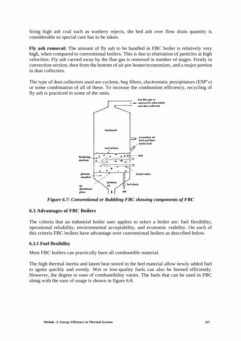
Module -2: Energy Efficiency in Thermal Systems 167
firing high ash coal such as washery rejects, the bed ash over flow drain quantity is
considerable so special care has to be taken.
Fly ash removal: The amount of fly ash to be handled in FBC boiler is relatively very
high, when compared to conventional boilers. This is due to elutriation of particles at high
velocities. Fly ash carried away by the flue gas is removed in number of stages. Firstly in
convection section, then from the bottom of air pre heater/economizer, and a major portion
in dust collectors.
The type of dust collectors used are cyclone, bag filters, electrostatic precipitators (ESP’s)
or some combination of all of these. To increase the combustion efficiency, recycling of
fly ash is practiced in some of the units.
Figure 6.7: Conventional or Bubbling FBC showing components of FBC
6.3 Advantages of FBC Boilers
The criteria that an industrial boiler user applies to select a boiler are: fuel flexibility,
operational reliability, environmental acceptability, and economic viability. On each of
this criteria FBC boilers have advantage over conventional boilers as described below.
6.3.1 Fuel flexibility
Most FBC boilers can practically burn all combustible material.
The high thermal inertia and latent heat stored in the bed material allow newly added fuel
to ignite quickly and evenly. Wet or low-quality fuels can also be burned efficiently.
However, the degree to ease of combustibility varies. The fuels that can be used in FBC
along with the ease of usage is shown in figure 6.8.

Module -2: Energy Efficiency in Thermal Systems 168
Figure 6.8: Fuels for FBC boiler and their Ease of Use
6.3.2 Operational Reliability
A boiler's operational reliability depends on many factors namely, the auxiliary equipment
that pre-treats the fuel (e.g., crushing, screening, feeding); the boiler feed water treatment
unit that prepares the water to meet boiler requirements; and the systems that handle
combustion flue gas and refuse.
FBC are more reliable than conventional boilers due to following reasons.
Non usage of pneumatic feeding system
Operation at lower and more uniform temperature than conventional boilers.
Because of the turbulent mixing and the efficient transfer of heat, temperatures
within the fluidized bed are uniform which minimizes hot spots. These lower
temperatures are below the melting points of most ashes which avoids the slagging
and fouling of heat transfer surfaces with melted ash, one of the major problems
encountered in solid-fuel fired boilers.
Having no moving parts that need continuous and frequent maintenance.
6.3.3 Environmental Acceptability
Fluidized bed combustion is more environmentally friendly as it suppresses sulphur
dioxide at the time of combustion rather than removing it from flue gases later with
expensive and sometimes difficult-to-operate, post-combustive ("scrubbing") devices. By
virtue of low combustion temperature, the FBC boiler exhibits attractive sulphur retention
Net
calo
rific
valu
e
(MJ
/kg)
Fuel rank

Module -2: Energy Efficiency in Thermal Systems 169
characteristics and low nitrogen oxides emission thus enabling a unit to meet the
Bangladesh boiler emissions norms as given in table 6.1 in cost effective terms.
Table 6.1: Standards for Gaseous emissions for Boiler of Industrial Unit
S. No. Parameters Standards
(mg/Nm3)
Power plant
1. Particulate matter
a. Capacity ≥200 MW 150
b. Capacity <200 MW 350
2. Oxides of nitrogen for Gas fuel based power plant
a. ≥ 500 MW 50 ppm
b. 200 – 500 MW 40 ppm
c. < 200 MW 30 ppm
Industrial Boiler
1. Soot and particulate (fuel based)
a. Coal 500
b. Gas 100
c. Oil 300
2. Oxides of Nitrogen (fuel based)
a. Coal 600
b. Gas 150
c. Oil 300
Stack height for Power and Industrial boiler
a. Steam per hour upto 15 tons 11
b. Steam per hour more than 15 tons 14Q0.3
Where, Q = Emission of sulphur dioxide in kg/hr.
Boiler using bagasse
1. Particulate matter
a. Step grade 250
b. Pulsating 500
c. Horse shoe spreader stocker 800
6.3.4 Economic Viability
The unique feature of FBC to burn inexpensive, low-grade, and high sulphur coals indicate
a favourable cost differential in using FBC.
As they yield a rate of heat transfer five to ten times more efficient than the rate of heat
transfer achieved through conventional coal-firing boilers it leads to reducing the size of
boiler substantially, thus reducing costs.

Module -2: Energy Efficiency in Thermal Systems 170
Table 6.2: Summary of Advantages and Disadvantages of FBC Boilers
Advantages Disadvantages
Fuel flexibility
In situ SO2 removal
Low NOx emission
Good system availability
No slagging
Low corrosion rate
Easy sizing of fuel
Higher power of air van
Larger cross-section of a furnace
Higher surface loss of heat
Higher carbon-in-ash level
Higher erosion rate
The criteria for considering FBC boilers is given in Figure 6.9.

Module -2: Energy Efficiency in Thermal Systems 171
Site specific variables
→
Ch
oic
e o
f Te
chn
olo
gy
→
Operating variables
→
Design variables
→
Operating effectiveness
→
Economics
Emission Requirements
Fuel availability Fuel used
Sulphur absorbent
NOx control
Bed temperature
Pressure
Gas velocity
Excess air
Particle size
Particle flow
Bed height
Steam parameters
Furnace configuration
Pollution control
Combustion efficiency
Sorbent utilisation
Fluidisation
Heat Transfer
Elutriation
Attrition
Corrosion
Erosion
Agglomeration ash
Control
Turndown
System efficiency o Thermal o Electrical
Solids distribution
Air distribution
Particle diffusion
Reliability
Pressure drop
Heat release
Tubing and fabrication
Structures
Controls
Auxiliaries
Water circulation
Maintenance
Steam headers
Construction time
Solids preparation and distribution
Air preparation and distribution
Type
Quality
Quantity
Arrangement of boiler functions:
o Economizer o Super-heater o Regenerator o Solids removal o Heat exchanger
(for solids)
Site specific components in case of:
Repower
Retrofit
Add-on
Conversion
Application:
Combined Heat and Power
Power generation
Process/space heating
Heat transfer surface
o Tube size o Arrangement o Orientation
Air distribution Location of draft fans
o Primary air
o Secondary air
Solids handling
Working fluid cycle (e.g. once through)
Sulphur absorbent regenerator
Refractory
Fuel preparation o Fuel feeding o Location o Number of
points
Figure 6.9: Overview of Variables influencing economic and technological performance

Module -2: Energy Efficiency in Thermal Systems 172
6.4 Types of Fluidized Bed Combustion Boilers
There are three variants of FBC technology.
The bubbling fluidized bed (BFB) was the first version of FBC technology also called
Atmospheric Classic Fluidised Bed Combustion System (AFBC). BFB technology is
well suited for utilisation of ‘difficult’ fuels such as high moisture fuels (e.g. wastes
and sludge’s), high-ash fuels (e.g. some types of municipal solid waste and refuse-
derived fuel) and low volatile fuels (including anthracite, culm and petroleum coke)
as well as for smaller industrial applications.
The circulating fluidized bed (CFB) also called Atmospheric Circulating (fast)
Fluidised Bed Combustion system (CFBC) is the second variant and is derived from
the BFB technology and surpasses its predecessor in terms of sulphur removal,
efficiency and scale. The basic difference between BFB and its successor CFB is the
fluidisation velocity, which is higher for CFB compared to BFB.
The third variant is a hybrid type of the BFB and CFB and is called Pressurised
Fluidised Bed Combustion System (PFBC). It was developed to combine the
advantages of both BFB and CFB and thus found its application to be in medium-
scaled (industrial) capacity range.
6.4.1 AFBC / Bubbling Bed
In this type of FBC coal is crushed to a size of 1 – 10 mm depending on the rank of coal,
type of fuel feeding and fed to the combustion chamber. The atmospheric air, which acts
as both the fluidization air and combustion air, is delivered at a pressure, and flows through
the bed after being preheated by the exhaust flue gases. The in-bed tubes carrying water
generally act as the evaporator.
Fluidized bed combustion is to be done in a relatively narrow temperature range within
which the bed must be operated. With coal, there is risk of clinker formation in the bed if
the temperature exceeds 950°C and combustion efficiency declines below 800°C. For
efficient sulphur retention the temperature should be in the range of 800 - 850° C.
The combustion gases pass over the super heater sections of the boiler, flow past the
economizer, the dust collectors and the air pre heaters before being exhausted to
atmosphere.
Almost all atmospheric bubbling bed boilers (AFBC) use the in-bed evaporator tubes for
extracting the heat from the bed to maintain the bed temperature. Typical fluidized bed
combustors of this type are shown in Figures 6.10 and 6.11.
The bubbling bed has heat transfer tubes in the bed of limestone, sand and fuel. The
velocity of fluidizing air is in the range of 1.2 to 3.7 m/sec. About 2 to 4 Kgs of solids are
recycled per kg of fuel burned.
The bed depth is usually 0.9 m to 1.5 m deep and the pressure drop averages about 1 inch
of water per inch of bed depth. The bulk of the bed consists of limestone, sand, ash, or
other material and a small amount of fuel. The rate at which air is blown through the bed
determines the amount of fuel that can be combusted.

Module -2: Energy Efficiency in Thermal Systems 173
1 Steam Drum ,2 Bed Superheater, 3 Bed
Evaporator, 4 Convection Superheater, 5
Economiser, 6 Windbox, 7 Air Distributor
Plate, 8 Hot Air Duct, 9 Cold Air Duct, 10
Air Preheater
Figure 6.10: Bubbling bed boiler-1 Figure 6.11: Bubbling bed boiler-2
6.4.2 Circulating Fluidised Bed Combustion (CFBC)
This CFB technology utilizes the fluidized bed principle in which crushed (6 –12 mm size)
fuel and limestone are injected into the furnace or combustor. The particles are suspended
in a stream of upwardly flowing air (60-70% of the total air), which enters the bottom of
the furnace through air distribution nozzles. The balance of combustion air is admitted
above the bottom of the furnace as secondary air. While combustion takes place at 840-
900°C, the fine particles (<450 microns) are elutriated out of the furnace with flue gas
velocity of 4-6 m/s. The particles are then collected by the solids separators and circulated
back into the furnace as shown in Figure 6.12.
The particles circulation provides efficient heat transfer to the furnace walls and longer
residence time for carbon and limestone utilization. The controlling parameters in the CFB
combustion process are temperature, residence time and turbulence.
In a circulating system the bed parameters are so maintained as to promote solids
elutriation from the bed. They are lifted in a relatively dilute phase in a solids raiser, and
a down-comer with a cyclone provides a return path for the solids. There are no steam
generating tubes immersed in the bed. Generation and super heating of steam takes place
in the convection section, water walls, at the exit of the riser.
CFBC boilers are generally claimed to be more economical than AFBC boilers for
industrial application requiring more than 75 – 100 T/hr of steam. For large units, the taller
furnace characteristics of CFBC boiler offers better space utilization, greater fuel particle
and sorbent residence time for efficient combustion and SO2 capture, and easier application
of staged combustion techniques for NOx control than AFBC generators.

Module -2: Energy Efficiency in Thermal Systems 174
The circulating bed is designed to move solids out of the furnace area and to achieve most
of the heat transfer outside the combustion zone. Some circulating bed units even have
external heat exchanges. The fluidizing velocity in circulating beds ranges from 3.7 to 9
m/sec and solid recycle is 50 to 100 kg per kg of fuel burnt.
Furnace temperature is roughly the same in both AFBC and CFBC, but the circulating bed
is said to achieve better calcium to sulphur utilization – 1.5 to 1 vs. 3.2 to 1 for the bubbling
bed.
CFBC requires mechanical cyclones to capture and recycle the bed material and the
requirement of a tall boiler.
A CFB could be good choice if the following conditions are met.
Capacity of boiler is large to medium
Sulphur emission and NOx control is important
The boiler is required to fire low grade fuel or fuel with fluctuating quality.
Major performance features of the circulating bed system are as follows:
It has a high processing capacity because of the high gas velocity through the system.
The temperature of about 870°C is reasonably constant throughout the process
because of the high turbulence and circulation of solids. The low combustion
temperature also results in minimal NOx formation.
Sulphur present in the fuel is retained in the circulating solids in the form of calcium
sulphate is removed in solid form. The use of limestone or dolomite sorbents allows
a higher sulphur retention rate.
The combustion air is supplied at 1.5 to 2 psig rather than 3-5 psig as required by
bubbling bed combustors.
It has high combustion efficiency.
It has a better turndown ratio than bubbling bed systems.
In a bubbling bed system, the surface generally is perpendicular to the flow.
Figure 6.12: Circulating bed boiler design

Module -2: Energy Efficiency in Thermal Systems 175
Table 6.3: Comparison of BFBC and CFBC
Parameter Units BFBC CFBC
Combustion Temperature °C 760 -870 800 - 900
Fuel particle size mm 0 - 50 0 - 25
Fluidization Velocities m/s 1 - 3 03-Oct
Solids Circulation No Yes
Particle Concentration
High in bottom, low in free board
Gradually decreases with furnace height
Limestone (a) particle size mm 0.3 - 0.5 0.1 - 0.2
Average steam parameters
Steam flow range Kg/s 36 (13 - 139) 60 (12 - 360)
Steam temperature range °C 466 (150 - 543) 506 (180 - 580)
Steam Pressure range bar 72 (10 - 160) 103 (10 - 275)
Size T/hr All sizes 45-680
Combustion Efficiency % 2 - 3 % Better than BFBC
Sorbent use
~100% more than CFBC
Bed Area 2.5 times of CFBC
Fuel Feed Over-bed/Under-bed In-bed
Heat recovery In-bed tubes No in-bed tubes
Boiler controls Conventional Conventional
Material handling Conventional Conventional
Start-up Hrs. 4 8
O & M Lower than BFBC
Plant power Auxiliary
Similar if BFBC is over-bed and more if BFBC is under-
bed feed system
(a): Applicable in case when limestone is used for in-bed sulphur removal.
Source:
Development of fluidized bed combustion—An overview of trends, performance and
cost Joris Koornneef , Martin Junginger, Andre´ Faaij, in Progress in Energy and
Combustion Science 33 (2007) 19–55
Comparison of Bubbling and Circulating Fluidized Bed Industrial Steam Generation by
R N Gaglia and A Hall in Proceedings of the 1987 international Conference on FBC
6.4.3 Pressurized Fluid Bed Combustion
Pressurised Fluidized Bed Combustion (PFBC) is a variation of fluid bed technology that
is meant for large scale coal burning applications. In PFBC, the bed vessel is operated at
pressure up to 16 ata (16 kg/cm2).
The off-gas from the fluidized bed combustor drives the gas turbine. The steam turbine is
driven by steam raised in tubes immersed in the fluidized bed. The condensate from the
steam turbine is pre-heated using waste heat from gas turbine exhaust and is then taken as
feed water for steam generation.
The PFBC system can be used for cogeneration or combined cycle power generation. By
combining the gas and steam turbines in this way, electricity is generated more efficiently
than in conventional system. The overall conversion efficiency is higher by 5% to 8%.
(Refer Figure 6.13).

Module -2: Energy Efficiency in Thermal Systems 176
Figure 6.13: PFBC Boiler for Cogeneration
At elevated pressure, the potential reduction in boiler size is considerable due to increased
amount of combustion in pressurized mode and high heat flux through in-bed tubes. A
comparison of size of a typical 250 MW PFBC boiler versus conventional pulverized fuel-
fired boiler is shown in the Figure 6.14.
Figure 6.14: Comparison of PFBC boiler versus pulverized fuel boiler
6.5 Retrofitting of FBC Systems to Conventional Boilers
Retrofitting fluidized bed coal fired combustion systems to conventional boilers has been
carried out successfully in many countries. The important aspects to be considered in
retrofit projects are:
Water/steam circulation design
Furnace bottom-grate clearance
Type of particulate control device
Fan capacity
Availability of space.

Module -2: Energy Efficiency in Thermal Systems 177
Retrofitting of a fluidized bed combustor to a conventional stoker fired water tube boiler
may involve:
The replacement of grate by a distributor plate with short stand pipes for
admitting air from the wind box located under neath.
Installation of stand pipes to remove ash from the bed.
Provision of horizontal hair pin tubes in the bed with a pump for forced
circulation from the boiler drum.
Modification of crusher to size the coal/limestone mixture for pneumatic
under-bed injection of the mixture.
Conversion of a conventional coal fired system to a fluidized bed combustion system can
be accomplished without effecting major changes, after making a cost-benefit analysis. Oil
fired boilers can also be converted to coal fired fluidized bed combustion systems.
However, it has to be examined on a case to case basis.
6.6 Advantages of Fluidized Bed Combustion Boilers
1. High Efficiency
FBC boilers can burn fuel with a combustion efficiency of over 95% irrespective of ash
content. FBC boilers can operate with overall efficiency of 84% (plus or minus 2%).
2. Reduction in Boiler Size
High heat transfer rate over a small heat transfer area immersed in the bed result in overall
size reduction of the boiler.
3. Fuel Flexibility
FBC boilers can be operated efficiently with a variety of fuels. Even fuels like flotation
slimes, washer rejects, agro waste can be burnt efficiently. These can be fed either
independently or in combination with coal into the same furnace.
4. Ability to Burn Low Grade Fuel
FBC boilers would give the rated output even with inferior quality fuel. The boilers can
fire coals with ash content as high as 62% and having calorific value as low as 2,500
kcal/kg. Even carbon content of only 1% by weight can sustain the fluidized bed
combustion.
5. Ability to Burn Fines
Coal containing fines below 6 mm can be burnt efficiently in FBC boiler, which is very
difficult to achieve in conventional firing system.
6. Pollution Control
SO2 formation can be greatly minimized by addition of limestone or dolomite for high
sulphur coals. 3% limestone is required for every 1% sulphur in the coal feed. Low
combustion temperature eliminates NO formation.
7. Low Corrosion and Erosion
The corrosion and erosion effects are less due to lower combustion temperature, softness
of ash and low particle velocity (of the order of 1 m/sec).
Module -2: Energy Efficiency in Thermal Systems 178
8. Easier Ash Removal — No Clinker Formation
Since the temperature of the furnace is in the range of 750 — 900 °C in FBC boilers, even
coal of low ash fusion temperature can be burnt without clinker formation. Ash removal is
easier as the ash flows like liquid from the combustion chamber. Hence less manpower is
required for ash handling.
9. Less Excess Air — Higher CO in Flue Gas 2
The CO2 in the flue gases will be of the order of 14 — 15% at full load. Hence, the FBC
boiler can operate at low excess air - only 20 — 25%.
10. Simple Operation, Quick Start-Up
High turbulence of the bed facilitates quick start up and shut down. Full automation of
start up and operation using reliable equipment is possible.
11. Fast Response to Load Fluctuations
Inherent high thermal storage characteristics can easily absorb fluctuation in fuel feed
rates. Response to changing load is comparable to that of oil fired boilers.
12. No Slagging in the Furnace-No Soot Blowing
In FBC boilers, volatilization of alkali components in ash does not take place and the ash
is non-sticky. This means that there is no slagging or soot blowing.
13. Provisions of Automatic Coal and Ash Handling System
Automatic systems for coal and ash handling can be incorporated, making the plant easy
to operate comparable to oil or gas fired installation.
14. Provision of Automatic Ignition System
Control systems using micro-processors and automatic ignition equipment give excellent
control with minimum manual supervision.
15. High Reliability
The absence of moving parts in the combustion zone results in a high degree of reliability
and low maintenance costs.
16. Reduced Maintenance
Routine overhauls are infrequent and high efficiency is maintained for long periods.
17. Quick Responses to Changing Demand
A fluidized bed combustor can respond to changing heat demands more easily than stoker
fired systems. This makes it very suitable for applications such as thermal fluid heaters,
which require rapid responses.
18. High Efficiency of Power Generation
By operating the fluidized bed at elevated pressure, it can be used to generate hot
pressurized gases to power a gas turbine. This can be combined with a conventional steam
turbine to improve the efficiency of electricity generation and give a potential fuel savings
of at least 4%.

Module -2: Energy Efficiency in Thermal Systems 179
6.7 Application Considerations with Biomass FBC Boilers
Biomass is a clean source of energy and is gaining huge popularity for FBC application in
Industry. Used judiciously, entrepreneurs can reduce the cost of steam generation and at
the same time reduce greenhouse gas emissions. With biomass fed boilers, the following
areas need attention:
Uneven spreading of biomass fuel on boiler grate can lead to secondary combustion in
the super-heater zone, resulting in overheating of super heater tubes and fluctuations
in steam pressure.
Frequent erosion of super-heater and economizer coils can occur, due to high silica
content in the biomass, especially in rice husk.
High extraneous matter in biomass (sand and mud) causes tube fouling and fluidized
bed to be drained more frequently, with resultant heat loss.
Carbon and dust coating of boiler tubes results in lowering of steam temperatures,
especially during soot blowing.
Presence of Pesticides (used during farming) adds to tube failure frequencies; mainly
due to potassium constituents.
Corrosive constituents in biomass adversely affect boiler internals, especially the
super-heater tubes. Chloride content in certain types of biomass (like cotton stalk, 8-
9%) can combine with sodium and potassium in high temperature regime to aggravate
the corrosion process.
Some boilers which use Red Gram husk/twigs as fuel pose corrosion problems at the
cold end (i.e., secondary super-heater and economizer tubes), due to the sulphur
content.
The biomass fuel mix fed to the boiler, in quite a few cases, contains a combination of
6 to 7 biomass types. Each biomass has a separate air-to fuel ratio, and it is difficult to
set a workable air—fuel ratio.
High moisture content in the biomass causes frequent jamming of the fuel in feeders,
leading to fluctuations in steam pressure and temperature.
High moisture content in the biomass also leads to plugging and choking of closely
spaced heating surfaces. This situation is further aggravated by the super-heater tube
coil with very close spacing, often the result of a desire to achieve a compact design.

Module -2: Energy Efficiency in Thermal Systems 180
Due to biomass fuel size variation, occurrence of unburnts in flue gases and bottom
ash is high, resulting in lower efficiency and also variation in steam pressure and
temperature.
Absence of biomass feed rate measurement mechanism leaves little room for accurate
assessment of heat rate/efficiency. Providing a weighing mechanism is difficult on
account of different biomass fuel combinations being used, with different (and low)
bulk densities.
Degradation of biomass during storage in exposed ambient wet atmosphere leads to
loss of heat value. Loss of material due to windage and carpet loss, coupled with loss
of heat value on account of decay (inherent biomass characteristics), can cause an error
in assessment of input fuel energy (as the input heat is customarily evaluated based on
received biomass quantities and GCV).
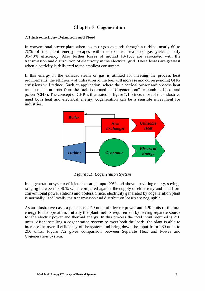
Module -2: Energy Efficiency in Thermal Systems 181
Chapter 7: Cogeneration
7.1 Introduction– Definition and Need
In conventional power plant when steam or gas expands through a turbine, nearly 60 to
70% of the input energy escapes with the exhaust steam or gas yielding only
30-40% efficiency. Also further losses of around 10-15% are associated with the
transmission and distribution of electricity in the electrical grid. These losses are greatest
when electricity is delivered to the smallest consumers.
If this energy in the exhaust steam or gas is utilized for meeting the process heat
requirements, the efficiency of utilization of the fuel will increase and corresponding GHG
emissions will reduce. Such an application, where the electrical power and process heat
requirements are met from the fuel, is termed as “Cogeneration” or combined heat and
power (CHP). The concept of CHP is illustrated in figure 7.1. Since, most of the industries
need both heat and electrical energy, cogeneration can be a sensible investment for
industries.
Figure 7.1: Cogeneration System
In cogeneration system efficiencies can go upto 90% and above providing energy savings
ranging between 15-40% when compared against the supply of electricity and heat from
conventional power stations and boilers. Since, electricity generated by cogeneration plant
is normally used locally the transmission and distribution losses are negligible.
As an illustrative case, a plant needs 40 units of electric power and 120 units of thermal
energy for its operation. Initially the plant met its requirement by having separate source
for the electric power and thermal energy. In this process the total input required is 260
units. After installing a cogeneration system to meet both the loads, the plant is able to
increase the overall efficiency of the system and bring down the input from 260 units to
200 units. Figure 7.2 gives comparison between Separate Heat and Power and
Cogeneration System.
Boiler
Heat
Exchanger
Utilisable
Heat
Electrical
Energy Generator Turbine

Module -2: Energy Efficiency in Thermal Systems 182
Figure 7.2: Comparison between energy inputs without and with cogeneration
In a cogeneration system, if less electricity is generated than needed, it will be necessary
to buy extra. However, when the scheme is sized according to the heat demand, normally,
more electricity than needed is generated. The surplus electricity can be sold to the grid. It
can also be supplied to another customer via the distribution system, which is called the
wheeling of power. As a rough guide. Cogeneration is likely to be suitable if there is
constant heat demand for atleast 4,500 hours per year.
7.2 Classification of Cogeneration Systems
There are two main types of cogeneration concepts: “Topping Cycle” plants, and
“Bottoming Cycle” plants. A topping cycle plant generates electricity or mechanical power
first whereas a bottoming cycle plant generates heat first.
Case A: Separate Heat and Power
ELECTRICITY HEAT
Fuel input = 100 units Fuel input = 160 units
Electricity
generator
(Efficiency 40%)
Boiler
(Efficiency 75%)
Output
40 units electricity Output
120 units heat
(TOTAL FUEL
INPUT = 260 units)
ELECTRICITY HEAT
Fuel input = 200 units
Electricity
generator
(efficiency 20%)
Output
40 units electricity Output
120 units heat
(TOTAL FUEL
INPUT = 200 units)
Case B: Combined Heat and Power

Module -2: Energy Efficiency in Thermal Systems 183
7.2.1 Topping Cycle
There are four types of topping cycle cogeneration systems. They are:
Topping cycle cogeneration systems are of two types:
1) Fuel can be burned directly in either a gas turbine or a diesel engine to produce
electrical or mechanical power and the exhaust is used to provide process heat or
process steam. This is called a combined- cycle topping system. The process is
shown in figure 7.3.
Figure 7.3: Steam turbine topping systems
2) Fuel can be burned initially to produce high-pressure steam which is then passed
through a steam turbine to produce power, and the exhaust is used as process steam.
A gas turbine or diesel engine producing electrical or mechanical power followed
by a heat recovery boiler to create steam to drive a secondary steam turbine. This
is a steam-turbine topping system.
Figure 7.4: Steam turbine topping systems

Module -2: Energy Efficiency in Thermal Systems 184
3) A third type employs hot water from an engine jacket cooling system flowing to a
heat recovery boiler, where it is converted to process steam and hot water for space
heating.
Figure 7.5: Diesel or gas engine topping systems
4) The fourth type is a gas-turbine topping system. A natural gas turbine drives a
generator. The exhaust gas goes to a heat recovery boiler that makes process steam
and process heat.
Figure 7.6: Gas turbine topping systems
7.2.2 Bottoming Cycle:
Bottoming cycle plants are much less common than topping cycle plants. These plants
exist in heavy industries such as glass or metals manufacturing where very high
temperature furnaces are used. The Figure 7.7 illustrates the bottoming cycle where fuel is
burnt in a furnace to produce synthetic rutile. The waste gases coming out of the furnace
is utilized in a boiler to generate steam, which drives the turbine to produce electricity.

Module -2: Energy Efficiency in Thermal Systems 185
Figure 7.7: Bottoming cycle
7.3 Types of Cogeneration Systems
Steam turbine
Gas turbine
Diesel engine
7.3.1 Steam Turbine
Steam turbines are the most commonly employed prime movers for cogeneration
applications. In the steam turbine, high pressure steam generated in a boiler or heat
recovery steam generator (HRSG) is expanded to a lower pressure level, converting the
thermal energy of high pressure steam to kinetic energy through nozzles and then to
mechanical power through rotating blades. Boiler fuels can include fossil fuels such as
coal, oil and natural gas or renewable fuels like wood or municipal waste.
Figure 7.8: Steam turbine cogeneration system

Module -2: Energy Efficiency in Thermal Systems 186
The thermodynamic cycle for the steam turbine is the rankine cycle, although a number of
different cycles are also used, such as the Reheat, the Regenerative and the combined
cycle. The rankine cycle is the basis for conventional power generating stations and
consists of a heat source (boiler) that converts water to high- pressure steam. The steam
flows through the turbine to produce power and may be wet, dry saturated or superheated.
Depending on the pressure (or temperature) levels at which process steam is required,
back-pressure steam turbines can have different configurations. In extraction and double
extraction back-pressure turbines, some amount of steam is extracted from the turbine after
being expanded to a certain pressure level. The extracted steam meets the heat demands at
pressure levels higher than the exhaust pressure of the steam turbine.
The efficiency of a back-pressure steam turbine cogeneration system is the highest. In
cases where 100 per cent back-pressure exhaust steam is used, the only inefficiencies are
gear drive and electric generator losses, and the inefficiency of steam generation.
Therefore, with an efficient boiler, the overall thermal efficiency of the system could reach
as much as 90 percent.
High pressure steam Extracted steam Exhaust steam
Simple backpressure Extraction backpressure Double extraction
backpressure
Figure 7.9: Configurations for back pressure steam turbines
Back-Pressure turbine: In this type steam enters the turbine chamber at High Pressure
and expands to Low or Medium Pressure. Enthalpy difference is used for generating
power /work.
Total Condensing turbine: In this type, steam entering at High / Medium Pressure
condenses in a surface condenser and work is done till it reaches the Condensing pressure
(vacuum).
Extraction cum Condensing steam turbine: In this high Pressure steam enters the
turbine and passes out from the turbine chamber in stages. The Figure 7.8 shows a two
stage extraction cum condensing turbine. In this MP steam and LP steam pass out to meet
the process needs. Balance quantity condenses in the surface condenser. The Energy
difference is used for generating Power. This configuration meets the heat-power
requirement of the process.
The extraction condensing turbines: These turbines have higher power to heat ratio in
comparison with back-pressure turbines. Although condensing systems need more
auxiliary equipment such as the condenser and cooling towers, better matching of electrical
power and heat demand can be obtained where electricity demand is much higher than the
steam demand and the load patterns are highly fluctuating.

Module -2: Energy Efficiency in Thermal Systems 187
The overall thermal efficiency of an extraction condensing turbine cogeneration system is
lower than that of back pressure turbine system, basically because the exhaust heat cannot
be utilized (it is normally lost in the cooling water circuit). However, extraction condensing
cogeneration systems have higher electricity generation efficiencies.
7.3.2 Gas Turbine
In gas turbines fuel is burnt in a pressurized combustion chamber using combustion air
supplied by a compressor. These hot gases expand through the blades on the turbine rotor
causing them to move generating mechanical energy.
In conventional Gas turbine, gases enter the turbine at 900 to 1000°C and leave at 400 to
500 °C. Residual energy in the form of hot exhaust gases can be used to generate wholly
or partly, the thermal (steam) demand of the site.
The available mechanical energy can be applied in the following ways:
to produce electricity with a generator (most applications);
to drive pumps, compressors, blowers, etc.
A gas turbine operates under exacting conditions of high speed and high temperature. The
hot gases supplied to it must be free of particulates which would erode the blades and
contain no more than minimal amounts of contaminants, which would cause corrosion
under operating conditions. High-premium fuels are therefore most often used, particularly
natural gas. Distillate oils such as gas oil LPGs and Naphtha are suitable.
Figure 7.10: Gas turbine
7.3.2.1 Gas Turbine Efficiency
Turbine Efficiency is the ratio of actual work output of the turbine to the net input energy
supplied in the form of fuel. For standalone Gas Turbines, without any heat recovery
system the efficiency will be as low as 35 to 40%. This is attributed to the blade efficiency
of the rotor, leakage through clearance spaces, friction, irreversible turbulence etc.
7.3.2.2 Increasing Overall Efficiency
Since Exhaust gas from the Gas Turbine is high, it is possible to recover energy from the
hot gas by a Heat Recovery Steam Generator and use the steam for process.

Module -2: Energy Efficiency in Thermal Systems 188
7.3.2.3 Net Turbine Efficiency
Above efficiency figures did not include the energy consumed by air compressors, fuel
pump and other auxiliaries.
Air compressor alone consumes about 50 to 60 % of energy generated by the turbine.
Hence net turbine efficiency, which is the actual energy output available will be less than
what has been calculated. In most Gas Turbine plants, air compressor is an integral part of
Turbine plant.
7.3.3 Diesel Engine Systems
This system provides process heat or steam from engine exhaust. The engine jacket cooling
water heat exchanger and lube oil cooler may also be used to provide hot water or hot air.
There are, however, limited applications for this. As these engines can use only fuels like
HSD, distillate, residual oils, natural gas, LPG etc. and as they are not economically better
than steam/gas turbine, their use is not widespread for co-generation. One more reason for
this is the engine maintenance requirement.
7.4 Methods for Calculating CHP System Efficiency
Two efficiency metrics namely Total system efficiency and Effective electric efficiency
are used to compare CHP systems with SHP systems:
Total system efficiency refers to the sum of the useful power output (in MWh expressed
in Btu/hr) and useful thermal outputs (in Btu/hr) divided by the total fuel input (in Btu/hr)
and is the more commonly cited efficiency metric.
Effective electric efficiency refers to the electricity output divided by the additional fuel
the CHP system uses over and above what would have been used by a conventional system
to meet the facility’s thermal energy load.
Both efficiency metrics consider all the outputs of CHP systems and reflect the benefits of
CHP. Since each metric measures a different performance characteristic, the purpose and
calculated value of each type of efficiency metric differs. For example, the total system
efficiency is typically most appropriate for comparing CHP system energy efficiency with
the efficiency of a site’s SHP options. The effective electric efficiency is typically used to
compare the CHP system with conventional electricity production (i.e., the grid).
In general, a CHP system’s total system efficiency differs from its effective electric
efficiency by 5% to 15%.
7.5 Typical Cogeneration Performance Parameters
The following Table 7.1 gives typical Cogeneration Performance Parameters for different
Cogeneration Packages giving heat rate, overall efficiencies etc.

Module -2: Energy Efficiency in Thermal Systems 189
Table 7.1: Typical Cogeneration Performance Parameters
Prime Mover in
Cogen. Package
Nominal
Range
(Electrical)
Electrical
Generation to
Heat Rate
(kCal / kWH)
Efficiencies, %
Electrical
Conversion
Thermal
Recovery
Overall
Cogeneration
Smaller
Reciprocating
Engines
10 – 500
kW
2650 - 6300 20-32 50 74-82
Larger Reciprocating
Engines
500 – 3000
kW
2400 - 3275 26-36 50 76-86
Diesel Engines 10-3000
kW
2770 - 3775 23-38 50 73-88
Smaller Gas
Turbines
800-10000
kW
2770-3525 24-31 50 74-81
Larger Gas
Turbines
10-20 MW 2770-3275 26-31 50 78-81
Steam Turbines 10-100
MW
2520-5040 17-34 - -
Note: Adapted from Cogeneration Handbook California Energy Commission, 1982
7.6 Heat: Power Ratio
Cogeneration is likely to be most attractive when the demand for both steam and power is
balanced i.e. consistent with the range of steam (Heat) to power output ratios that can be
obtained from a suitable cogeneration plant.
Heat-to-power ratio defined as the ratio of thermal energy to electricity required by the
energy consuming facility and expressed in different units such as Btu/kWh, kcal/kWh,
kW/kW, etc. It is one of the most important technical parameters influencing the selection
of the type of cogeneration system. The proportions of heat and power needed (heat to
power ratio) vary from site to site, so the type of plant selected should match demands as
closely as possible. The plant may therefore be set up to supply part or all of the site heat
and electricity loads, or an excess of either may be exported if a suitable customer is
available.
Heat-to-power ratios of different cogeneration systems and for certain energy intensive
industries are shown in Table 7.2 & 7.3.
Energy Utilisation Factor
Energy Utilisation Factor (EUF) is the percentage of useful output (i.e.) a combination of
electrical output and thermal output to fuel heat input. The formula for EUF is given below.

Module -2: Energy Efficiency in Thermal Systems 190
The electrical output is the useful power generation from the turbine and the thermal output
is the useful extraction from turbine for process heating. The fuel heat input is the fuel
flow rate multiplied by its calorific value.
Table 7.2: Heat-to-power ratios & key parameters of cogeneration systems
Cogeneration System Heat-to- Power
ratio (KW/KW)
Power Output
(as % of fuel
input)
Overall
efficiency %
Back-pressure steam turbine 4.0-14.3 14-28 84-92
Extraction-condensing steam
turbine
2.0-10 22-40 60-80
Gas turbine 1.3-2.0 24-35 70-85
Combined Cycle 1.0-1.7 34-40 69-83
Reciprocating Engine 1.1-2.5 33-53 75-85
Table 7.3: Typical Heat: Power ratios for certain energy intensive industries
Industry Minimum Maximum Average
Breweries 1.1 4.5 3.1
Pharmaceuticals 1.5 2.5 2.0
Fertilizer 0.8 3.0 2.0
Food 0.8 2.5 1.2
Paper 1.5 2.5 1.9
7.7 Factors for selection of cogeneration system
Following factors should be given due consideration in selecting the most appropriate
cogeneration system for a particular industry.
Normal as well as maximum/minimum power load and steam load in the plant,
and duration for which the process can tolerate without these utilities, i.e.
criticality and essentiality of inputs.
What is more critical - whether power or steam, to decide about emergency back-
up availability of power or steam.
Anticipated fluctuations in power and steam load and pattern of fluctuation,
sudden rise and fall in demand with their time duration and response time required
to meet the same.
Under normal process conditions, the step by step rate of increase in drawl of
power and steam as the process picks up - whether the rise in demand of one utility
is rapid than the other, same or vice-versa.
Type of fuel available - whether clean fuel like natural gas, naphtha or high speed
diesel or high ash bearing fuels like furnace oil, LSHS, etc or worst fuels like coal,
lignite, etc., long term availability of fuels and fuel pricing.
Commercial availability of various system alternatives, life span of various
systems and corresponding outlay for maintenance.
In general, simultaneous demands for heat and power must be present for at least
4,500 h/year, although there are applications where CHP systems may be cost
effective with fewer hours. For example, when electricity rates are high or when
the local power provider offers incentives, this operating period could be as low
as 2,200 h/year.

Module -2: Energy Efficiency in Thermal Systems 191
Power-to-heat ratio for the plant should not fluctuate more than 10%.
Influence exerted by local conditions at plant site, i.e. space available, soil
conditions, raw water availability, infrastructure and environment.
Project completion time.
Project cost and long term benefits.
Figure 7.11: Framework for Evaluating CHP viability
Collect site-specific data
and Assess Technical
Feasibility
Is CHP
Technically
Feasible?
Identify CHP options and
Develop Preliminary CHP
System Designs
Conduct Economic
Screening Analysis of
Each CHP System
Is CHP
Economicall
y Feasible?
Establish strategies for
overcoming implementation
Barriers
Is CHP
viable?
Implement CHP
Terminate CHP
Planning
Yes
Yes
Yes
No
No
No

Module -2: Energy Efficiency in Thermal Systems 192
7.8 Operating Strategies for Cogeneration Plant
For cogeneration plant there are three main operating regimes:
The unit is operated to provide base load electrical and thermal output. Any shortfall is supplemented with electricity
from external public/private utility and heat from stand-by boilers or boost ( thermic fluid) heaters;
The unit is operated to provide electricity in excess of the site’s requirements, for export, whilst all the thermal output is
used on site;
The unit is operated to provide electricity for site, with or without export, and the heat produced is used on site with the
surplus being exported to off-site customers.
Table 7.4: Characteristics of Prime Movers for CHP Applications a
Prime Mover Characteristic
Steam Turbine Gas turbine Micro turbine
Reciprocating Engine
Compression Ignition
Spark Ignition
Capacity, MW 0.05 to > 250 0.5 to 250 0.03-0.35 0.03 to 4 0.05 to 5
Power-to-heat ratio 0.05 to 0.2 0.5 to 2 0.4 to 0.7 0.5 to 1 0.5 to 1
Fuels All types of fuel can be burned to
produce steam
Natural gas, bio gas, propane and distillate fuel oil
Natural gas, Waste and sour gases, gasoline, kerosene, diesel and
distillate fuel oil
Natural gas, diesel and residual oil
Natural gas, bio gas, propane, land fill gas
and gasoline
Installed cost, $/KW 200 -1000 400 -1800 1300 -2500 900 - 1500 901 - 1500
Maintenance cost, $/KWh
≤ 0.002 0.003 - 0.01 ≤ 0.018 0.005 - 0.015 0.007 - 0.02
Overhaul period, h > 50000 12000 - 50000 5000 - 40000 25000 - 30000 24000 - 60000
Start-up time Hours Minutes Minutes Seconds Seconds
Total CHP efficiency (HHV) b
70 - 85 % 70 - 75 % 65 - 75 % 70 - 80 % 70 - 80 %
CHP electrical efficiency (HHV) c
20 - 40 % 22 - 36 % 18 - 29 % 27 - 45 % 22 - 40 %
Availability Nearly 100% 90 - 98 % 90 - 98 % 90 - 95 % 92 - 97 %
Noise High High High Moderate High
Service life 30 years or more 30000 - 100000 hrs 40000 - 80000 hrs 15 - 25 years 15 - 25 years
Part-load operation Good Poor Satisfactory Good Satisfactory
NOx control options Unnecessary but may be required as
part of steam supply system.
Steam or water injection, lean
premixed combustion, SCR,
Lean premixed combustion, SCR,
SNCR and SCONOXTM
Lean air-fuel mixture, SCR,
SNCR and SCONOXTM
Lean air-fuel mixture, staged ignition, catalytic 3-way
conversion(TWC),

Module -2: Energy Efficiency in Thermal Systems 193
Prime Mover Characteristic
Steam Turbine Gas turbine Micro turbine
Reciprocating Engine
Compression Ignition
Spark Ignition
SNCR and SCONOXTM
SCR, SNCR and SCONOXTM
Preferred uses for recovered heta
Process heat, hot water and low-
pressure to high pressure steam
Process heat, hot water and low-
pressure to high pressure steam
Process heat, hot water and low-pressure steam
Hot water and low-pressure
steam
Hot water and low-pressure steam
Temperature of rejected heat, °F
Varies depending on extraction conditions
500 -1100 400 - 600 180 - 900 180 - 1200
Operating mode Load-tracking and continuous base-loaded operation
Base-loaded, load-tracking, and peak shaving operations
Base-loaded, load-tracking, and peak shaving operations
Base-loaded, load-tracking,
emergency and peak shaving
operations
Base-loaded, load-tracking, emergency
and peak shaving operations
Potential applications Topping-cycle, bottoming-cycle,
combined-cycle, and trigeneration CHP
systems
Topping-cycle, combined-cycle, and trigeneration
CHP systems
Topping-cycle, combined-cycle, and
trigeneration CHP systems
Topping-cycle, combined-cycle, and trigeneration
CHP systems
Topping-cycle, combined-cycle, and
trigeneration CHP systems
a Based on CHP systems that operate at least 8000 hrs/year
b Total CHP efficiency is a measure of ( the net electricity generated plus the net heat supplied to the process), divided by the total fuel input
c CHP electrical efficiency is a function of the net electricity generated, divided by the total fuel input

Module -2: Energy Efficiency in Thermal Systems 194
Table 7.5: Sources of Information for decision making
Required information
Sources of Information
Energy
Audit
Utility
Company
Fuel
Suppliersa
Equipment
Suppliers
Management Legal
authorities
Air -water quality
authority
Special
authoritiesb
Financial
Institutions
Total thermal loads, magnitude and profile X
Total electrical loads, magnitude and profile X
Cooling Loads X
Major load centers and energy consumers X
Anticipated load changers, Mission or Function changes X
Waste heat sources X
Waste fuel sources X
Complimentary off-site loads X
Present Electrical Energy Costs and Rate Formats X X
Projected Electrical Energy Rate structure X
Policies towards parallel generation X
Ownership/Operation policies and preferences X X
Cogenerator rate structure, Standby charges, Reliability
Requirements, Payment for Power to Grid X
Environmental and Siting Constraint Overview X
Tax and Investment Incentives X X
Regulations Related to Cogeneration X X
Present Fuel Costs X X
Projected fuel costs X X
Projected fuel availability X X
Fuel Characteristics and Properties X
Performance Data, Design and Off Design Conditions X
Fuel Consumption X
Fuel Flexibility X
Emisssions Data and Specifications X
Air Emission Regulations X X
Other Emission Regulations X X
Fiscal Policies X
Funding Sources X X
Cost and Condtions of financing X
Siting restrictions X X X
a Oil, Natural gas or Coal
b For example, Zoning, airport, Coastal
(Source : Cogneration Systems- Technical Report by E E Cooper 1980)

Module -2: Energy Efficiency in Thermal Systems 195
7.9 Relative Merits of Co-Generation Systems
The following Table 7.6 gives the advantages and disadvantages of various co-generation
systems:
Table 7.6: Advantages and disadvantages of various cogeneration systems
Variant Advantages Disadvantages
Back-pressure - High fuel efficiency rating Little flexibility in design and
operation
Steam turbine & fuel
firing in boiler Simple plant
Well-suited to low quality fuels
More capital investment
Low fuel efficiency rating
High cooling water demand
More impact on
environment
High civil const. cost due
to complicated foundations
Gas turbine with waste
heat recovery boiler Good fuel efficiency
Simple plant
Low civil const. Cost
Less delivery period
Less impact on environment
High flexibility in operation
Moderate part load
efficiency
Limited suitability for low
quality fuels
Combined gas & steam
turbine with waste heat
recovery boiler
Optimum fuel efficiency rating
Low relative capital cost
Less gestation period
Quick start up & stoppage
Less impact on environment
High flexibility in operation
Average to moderate part-
load efficiency
Limited suitability for low
quality fuels
Diesel Engine & waste
heat recovery Boiler &
cooling water heat
exchanger
Low civil const. Cost due to
block foundations & least no.
of auxiliaries
High Power efficiency
Better suitability as standby
power source
Low overall efficiency
Limited suitability for low
quality fuels
Availability of low
temperature steam
Highly maintenance prone.

Module -2: Energy Efficiency in Thermal Systems 196
7.10 Case Study
Economics of a Gas Turbine based Cogeneration System
Alternative I: Gas Turbine based Cogeneration.
Gas Turbine Parameters Units Quantity
Capacity of gas turbine generator KW 4000
Plant operating hours per annum hrs/ year 8000
Plant load factor (PLF) % 90%
Heat rate as per standard given by gas turbine suppliers KCal/KWH 3049.77
Waste heat boiler parameters- unfired steam output TPH 10
Steam temperature °C 200
Steam pressure Kg/ Sq.cm 8.5
Steam enthalpy Kcal/Kg 676.44
Fuel used Natural Gas
Calorific Value - LCV Kcal/ S Cu.m 9500
Price of gas BDT/1000 S Cu.m 3000
Capital investment for Cogeneration plant BDT 1300000
Cost Estimation of Power & Steam from Cogeneration Plant
Power generated = PLF x Plant Capacity x Operating hrs KWH/ Year 28800000
Heat input = Power generated x Heat rate given by turbine supplier
Kcal 87833376000
Natural gas(NG) required per annum = Heat input/ LCV of NG S cu.m 9245618.526
Annual cost of fuel = Gas consumed x price BDT 27736855.58
Annualised Cost of capital and operation charges BDT 29863000
Overall cost of power from cogeneration plant (Alternative -I Cost)
BDT 57599855.58
Cost of power BDT/KWH 1.999994985

Module -2: Energy Efficiency in Thermal Systems 197
Alternative-II Electric Power from State Grid & Steam from Natural Gas ( NG) Fired Boiler
Boiler installed in plant TPH 10
Cost of electric power from grid BDT/KWH 3
Capital investment for 10TPH, 8.5 kg/cm2 @ 200°C NG fired fire tube boiler & all auxiliaries
BDT 8000000
Hours of operation hrs/ year 8000
Cost Estimation of Power & Steam from Grid and Steam from direct Conventional fired boiler
Cost of power from state grid for 28800000 KWH BDT/ year 86400000
Fuel cost for steam by separate boiler
Heat output in form of 10TPH steam per annum = Boiler capacity x steam Enthalpy x Hrs of operation
Kcal/ year 54115200000
Heat input required to generate 10TPH steam per annum @ 90% efficiency
Kcal/ year 60128000000
Natural gas(NG) required per annum = Heat input/ LCV of NG S cu.m/ year 6329263.158
Annual cost of fuel = Gas consumed x price BDT 18987789.47
Total cost for alternative II= Cost of grid power + fuel cost for steam
BDT 105387789.5
Alternative -I total cost BDT 57599855.58
Alternative -II total cost BDT 105387789.5
Differential cost BDT 47787933.89
(Note: In case of alternative II, there will be some additional impact on cost of steam due
to capital cost required for a separate boiler)
In the above case it can be seen that Alternative I is economical compared to Alternative
II.
7.11 Trigeneration
Trigeneration refers to simultaneous generation of steam (heat), power and refrigeration
through integrated systems. Industries requiring electricity, steam and cooling such as food
processing and cold storages find the concepts of tri-generation very attractive.
A combined cycle trigeneration plant could typically consist of a gas turbine generator,
waste heat recovery boiler, steam turbine, generator, and absorption chiller, to meet 100%
of the facility energy needs. Whenever the power is surplus, it is sold to the grid.
An illustrative trigeneration system schematic is presented in Figure 7.12.

Module -2: Energy Efficiency in Thermal Systems 198
Figure 7.12: Trigeneration: Power, Heating and Cooling
7.13 Microturbine
The Micro steam Turbine Power System is a compact, efficient power system that
generates electricity from pressure energy previously wasted in the steam pressure
reducing valves.
Figure 7.13 a) PRV, b) Micro turbine

Module -2: Energy Efficiency in Thermal Systems 199
In a typical steam system, a Pressure Reducing Valve (PRV) reduces the steam pressure
from P1 to P2 (Figure 7.13a). This pressure reduction happens in such a manner that the
total energy content (enthalpy) does not change (H1 = H2) and no shaft work is done.
On the other hand, when steam goes through a steam turbine, it expands and the steam
pressure reduces from P1 to P2 (Figure 7.13b). The steam turbine produces shaft
horsepower and as a result, the steam exit energy content (enthalpy) is lower when
compared to the PRV case.
Steam is used for heating purposes in the plant. The process heat duty is fixed by the plant
demand. Since the steam supplied to the process has a lower enthalpy, an additional
amount of steam is required to ensure the same available heat duty. This additional amount
of steam has an associated cost. Hence, power generated from a backpressure steam turbine
is not free.
Nevertheless, using a backpressure steam turbine can improve the overall plant and global
energy efficiency and more importantly, it can reduce total operating costs.
Example 7.1 Pressure reducing valve versus back pressure turbine
A chemical plant generates steam at 17.6 kg/cm2 (g) which is further reduced to 1.8 kg/cm2
(g) through a pressure reducing valve, for utilization in the process. The process requires
5189 MCaI/hr of heat. The plant has planned to replace the PRV with a back pressure
steam turbine.
Calculate the net savings per annum if the plant operates 8000 hrs/annum with the
following data and the data provided in the schematic diagrams.
Calorific value of fuel - 10,000 kcal/kg,
Fuel cost - BDT 25,000/Ton,
Grid cost of electricity charge - BDT 6/kWh.
Gear box efficiency - 98%
Alternator efficiency - 98%
Mechanical efficiency of turbine - 97%
a) Boiler and PRV operation

Module -2: Energy Efficiency in Thermal Systems 200
b) Boiler and Micro turbine operation:
The schematic of a back pressure steam turbine cogeneration system of process plant
operating round the clock with operating data is depicted below.
If the steam requirement of the process is to be increased to 44TPH which can be met by
the existing boiler through the back pressure turbine,
a) Find out the reduction in cost of electrical energy drawn from the grid per day due to
additional power generation ,assuming the same steam to power recovery as in the existing
case and at a grid electricity cost of BDT 7/kWh, Aux power remains the same.
b) Also find out the additional coal requirement per day?
Solution a) Present steam to power recovery ratio = 40,000 kg/hr / 3,200 kWh
= 12.5 kg/kWh
Additional steam generation = 4TPH
Additional power generation potential = 4000 kg/hr /12.5 kg/kWh
= 320 kW
Daily saving due to additional power generation = 320 kW x 24 hr x BDT 7
= BDT 53,760
Additional coal requirement per hour = 4000 x (780-135) / (0.8 x 4300)
= 750 kg/hr
b) Additional coal requirement per day = 750 kg/hr x 24
= 18,000 kg/day
= 18 Ton/day

Module -2: Energy Efficiency in Thermal Systems 201
Chapter 8: Waste Heat Recovery
8.1 Introduction
Industrial waste heat refers to the heat energy that is generated but not fully utilized in the
industrial processes and leaves the boundaries of a plant or building into the surrounding
environment. Waste heat is generally associated with waste streams of air, exhaust gases,
water, or other liquids. Waste heat losses arises both from equipment inefficiencies and
due to equipment and process requirements. These losses can be reduced by improving
equipment efficiency and installing waste heat recovery technologies.
Waste heat recovery (WHR) equipment is defined as any mechanical apparatus which
usefully recovers thermal energy from process waste streams that are above ambient
temperatures. The recovered heat is used to produce heat, generate power and in some
cases for cooling applications. The aim of this chapter is to provide an understanding of
why, when and how to recover waste heat and will cover the following aspects of WHR.
Opportunities and benefits of WHR
factors effecting waste heat recovery
applications of waste heat
WHR methods and technologies
Industry/sector specific applications of WHR technologies
Formulae for calculating heat losses
Case examples of WHR implemented
8.2 Opportunities and benefits of WHR
The best waste heat-recovery opportunities are those that have the following
characteristics:
The waste heat supply is constant.
The need is co-located with the waste heat supply.
The need is synchronized with the available waste heat.
The waste heat supply is higher in temperature than the need or
The need and the waste heat stream temperatures match the capabilities of
available heat-pumping equipment.
The size of the waste heat stream and the need are large enough to justify the
custom engineering required.
Benefits of ‘waste heat recovery’ can be broadly classified in two categories:
8.2.1 Direct Benefits:
Recovery of waste heat has a direct effect on the efficiency of the process. This is reflected
by reduction in the utility consumption and process cost.
8.2.2 Indirect Benefits:
a) Reduction in equipment sizes: Waste heat recovery reduces the fuel consumption,
which leads to reduction in the flue gas produced. If WHR systems are considered and

Module -2: Energy Efficiency in Thermal Systems 202
incorporated at design stage it may result in reduction in equipment sizes of all flue gas
handling equipments such as fans, stacks, ducts, burners, etc. In other modification and
retrofit cases possibility exists to reduce the size of equipment.
b) Reduction in auxiliary energy consumption: Reduction in equipment sizes gives
additional benefits in the form of reduction in auxiliary energy consumption like electricity
for fans, pumps etc.
c) Reduction in pollution: A number of toxic combustible wastes such as carbon
monoxide gas, sour gas, carbon black off gases, oil sludge, Acrylonitrile and other plastic
chemicals etc., when combusted/burnt in the thermal oxidation or incinerators serves dual
purpose of heat recovery and mitigation of the environmental pollution levels.
8.3 Factors affecting waste heat recovery
Before considering waste heat recovery it is important to consider why, when and how to
recover this waste heat to gain benefits. The following factors influence the selection of a
heat exchanger.
Source of the waste heat stream.
In few cases it is difficult to access and recover heat from unconventional sources such as
hot solid product streams (e.g., ingots) and hot equipment surfaces (e.g., sidewalls of
primary aluminum cells).
Amount of waste heat available
Once you find suitable waste heat source, it is important to establish that the source is
capable of supplying sufficient ‘quantity’ of heat, and that the heat is of a good enough
‘quality’ (i.e. temperature) to promote good heat transfer.
Characteristics of the waste heat stream
Essential considerations in making optional choice of waste heat recovery device:
1) Temperature of waste heat. (Temperature is a measure of quality of waste heat)
2) Flow rate of thefluid
3) Chemical composition of waste fluid
4) Properties of waste fluid (Cp, µ, ρ, ҡ)
5) Allowable pressuredrop
6) Minimum temperature to which waste heat can be cooled
7) Corrosive elements in the exhaust fluid
8) Temperature to which the designed fluid is to be heated
The quality of the heat is based on the waste stream temperature and it is divided into three
grades as mentioned in table 8.1 below. Higher the grade, the greater the potential value
for heat recovery.
Table 8.1: Different grades of heat
High Grade Medium Grade Low Grade
1100°F – 3000°F
(593°C – 1649°C)
400°F – 1100°F
(204°C – 593°C)
80°F – 400°F
(27°C – 204°C)
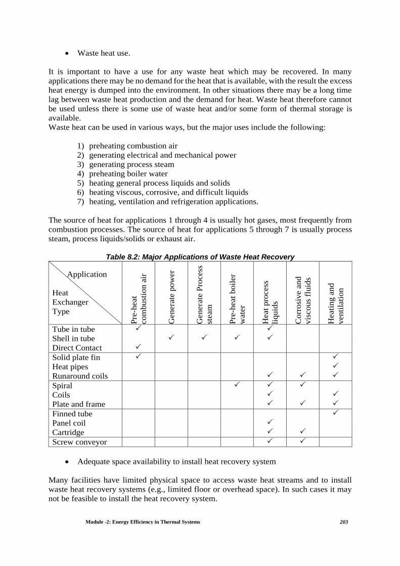
Module -2: Energy Efficiency in Thermal Systems 203
Waste heat use.
It is important to have a use for any waste heat which may be recovered. In many
applications there may be no demand for the heat that is available, with the result the excess
heat energy is dumped into the environment. In other situations there may be a long time
lag between waste heat production and the demand for heat. Waste heat therefore cannot
be used unless there is some use of waste heat and/or some form of thermal storage is
available.
Waste heat can be used in various ways, but the major uses include the following:
1) preheating combustion air
2) generating electrical and mechanical power
3) generating process steam
4) preheating boiler water
5) heating general process liquids and solids
6) heating viscous, corrosive, and difficult liquids
7) heating, ventilation and refrigeration applications.
The source of heat for applications 1 through 4 is usually hot gases, most frequently from
combustion processes. The source of heat for applications 5 through 7 is usually process
steam, process liquids/solids or exhaust air.
Table 8.2: Major Applications of Waste Heat Recovery
Application
Heat
Exchanger
Type
Pre
-heat
com
bust
ion a
ir
Genera
te p
ow
er
Genera
te P
rocess
steam
Pre
-heat
boil
er
wate
r
Heat
pro
cess
liquid
s
Corr
osi
ve a
nd
vis
cous
fluid
s
Heati
ng a
nd
venti
lati
on
Tube in tube
Shell in tube
Direct Contact
Solid plate fin
Heat pipes
Runaround coils
Spiral
Coils
Plate and frame
Finned tube
Panel coil
Cartridge
Screw conveyor
Adequate space availability to install heat recovery system
Many facilities have limited physical space to access waste heat streams and to install
waste heat recovery systems (e.g., limited floor or overhead space). In such cases it may
not be feasible to install the heat recovery system.

Module -2: Energy Efficiency in Thermal Systems 204
Primary energy saving possibility
Often the insertion of a heat exchange system increases the resistance of the fluid streams,
resulting in higher fan or pump energy consumption. Heat energy is therefore replaced by
electrical energy with no net energy savings.
Economic viability or cost effectiveness of WHR technology
Heat recovery devices can be expensive to install. It is therefore essential that the economic
payback period be determined before any investment is undertaken. If proper planning and
analysis is not carried out at the concept and design stage, impact of installation of a waste
heat recovery device is minimal or may even increase energy cost.
WHR technologies are similar to heat exchangers. The heat exchangers considered
unviable are now being considered for heat recovery for the following reasons
Heat exchange equipment costs came down making them viable
Fuel costs increased making an economic case for waste heat recovery
Regulatory requirements might have made it mandatory to install the same.
8.4 Overview of Waste Heat Recovery Methods and Technologies
Once the need and feasibility to install WHR equipment is established the next logical step
is to select the appropriate method for utilization of waste heat and the equipment required.
The common methods by which waste heat is utilized are as follows.
Direct utilization ( eg: for drying or process heating)
Energy Cascading (Using energy for high temperature application first followed
by using the rejected heat for low temperature applications. For example after
using high temperature and pressure steam for power generation low temperature
and pressure steam can be used for other processes or space heating).
Cogeneration (Producing electrical power and process heat simultaneously)
Recuperators ( Shell and tube, plate, coil, spiral heat exchangers)
Regenerators ( stationary or rotating type)
Waste heat boilers
WHR can be classified based on the maximum outlet temperature of recovered waste heat.
Accordingly based on waste heat stream temperatures WHR equipment is classified as
follows.
1) Gas-to-gas heat exchanger (Graphite heat exchangers, stack-type recuperators,
direct contact recuperator, plate fin (ceramic and metal) heat exchangers and
ceramic tubes)
2) Gas-to-liquid heat exchanger (waste heat boilers, economizers and power
generators)
3) Liquid-to-liquid heat exchanger (shell-and-tube, spiral, coil, finned-tube,
plate-and-frame (plate), and run-around heat exchangers)
4) Other low-temperature WHR equipment (heat pumps, and heat pipes )

Module -2: Energy Efficiency in Thermal Systems 205
At higher temperature, only gas-to-gas heat transfer is used because of the difficulties
encountered at these temperatures. At moderate temperatures (upto ~1000°F), gas-to-
liquid transfer is used (steam boilers). At lower temperatures, the dominant mode is liquid-
to-liquid heat recovery.
A brief description of commonly encountered heat exchangers is given in sections below.
8.4.1 Gas-to-gas Heat Exchanger
8.4.1.1 Graphite heat exchangers
Graphite heat exchangers have high thermal conductivity and frequently used for heating
or cooling of ultra-corrosive liquid chemicals. This specific design allows for heat recovery
between two ultra-corrosive fluids.
Figure 8.1: Graphite heat exchangers
(Source : GAB Neumann’s Annular Grove graphite heat exchangers)
8.4.1.2 Recuperators
This is the most common type of equipment used for waste heat recovery. In this heat
transfer is affected by bringing hot and cold streams adjacently where in heat from hot
fluid is transferred through the fluid separation barrier by means of convection and
conduction. The radiation recuperator gets its name from the fact that a substantial portion
of the heat transfer from the hot gases to the surface of the inner tube takes place by
radiative heat transfer. The cold air in the annuals, however, is almost transparent to
infrared radiation so that only convection heat transfer takes place to the incoming air.
Based on type of heat transfer they are classified as stack-type or direct contact
recuperators. Based on material of construction the direct contact recuperators are further
classified as metallic recuperator (used to recover heat from gases at about 1000oC) and
ceramic recuperator (used to recover heat from gases at about 1550oC).
Stack-type Recuperators
Stack type recuperators are used when the stack gas temperatures are high and heat transfer
dominantly occurs by radiation rather than convection. These are generally co-current heat
exchangers and are used for air preheating and is considered cost effective. It has an
advantage that hot gases do not have to be rerouted and fans are not required to produce a

Module -2: Energy Efficiency in Thermal Systems 206
draft. A major disadvantage is it required substantial heat difference between exhaust gas
and preheat air.
Figure 8.2: Preheating Combustion Air using a Recuperator in Furnace
Direct contact recuperator (ceramic and metal)heat exchangers
Direct contact recuperators provide highest air preheat temperature. These recuperators are
also called “checkers”. In this heat exchanger exhaust and air streams are alternated
between two sets of checkers. The exhaust stream heats the checkers in one set while the
air is being heated by the other. These are considered expensive and require considerable
space for duct work and damper arrangements.
Metallic recuperator
The simplest configuration for a recuperator is the metallic radiation recuperator, which
consists of two concentric lengths of metal tubing as shown in Figure 8.3
Figure 8.3: Metallic radiation recuperator
The inner tube carries the hot exhaust gases while the external annulus carries the ambient
air from the atmosphere which recovers the heat from hot exhaust gases. The heated
ambient air is supplied via air inlets of the furnace burners. This equivalent energy of hot
combustion air does not have to be supplied by the fuel. So, less fuel is burned for a given

Module -2: Energy Efficiency in Thermal Systems 207
furnace loading. The saving in fuel also means a decrease in combustion air requirements
and therefore lesser quantities of exhaust gas.
The principal limitation of metal recuperators is the reduced life of the liner at inlet
temperatures exceeding 1100°C.
Ceramic Recuperator
In order to overcome the temperature limitation of metallic recuperators, ceramic tube
recuperators have been developed. The materials of ceramic recuperators allow operation
on the gas side up to 1550°C and on the preheated air side up to 850°C. Early ceramic
recuperators were built of tile and joined with furnace cement, and thermal cycling caused
cracking of joints and rapid deterioration of the tubes. Later developments introduced
various kinds of short silicon carbide tubes which can be joined by flexible seals located
in the air headers.
Although the design of this heat exchanger may change with its particular application,
three types are widely used.
Flat plate recuperator
Flat plate recuperator (Figure 8.4) consists of a series of metal (usually aluminium) plates
separating ‘hot’ and ‘cold’ air or gas flows sandwiched in a box-like structure. The plates
are sealed in order to prevent intermixing of the two fluid flows. They are often used in
ducted air-conditioning installations to reclaim heat from the exhaust air stream without
cross contamination.
Figure 8.4: Flat Plate Recuperator
8.4.1.3 Plate fin (ceramic and metal)heat exchangers
Plate fin heat exchangers overcomes the problems associated with direct contact types and
for high temperature applications ( > 1360°F discharge air and > 1500 °F for flue gas) are
available in both metal and ceramic designs

Module -2: Energy Efficiency in Thermal Systems 208
Figure 8.5: Plate Fin Heat Exchanger Figure 8.6: Metallic Recuperator with
cross-counter flow design
8.4.1.4 Ceramic tubes
These are tubular heat exchangers made of ceramic tubes. They have problems of
differential thermal expansion of the ceramic tubes and related hardware which can cause
cracking and sealing problems.
Figure 8.7: Ceramic Re-entrant Tube Heat Exchanger
8.4.2 Gas-to-liquid heat exchanger
8.4.2.1 Waste Heat Boilers
Waste heat boilers are available with fire-tube or water-tube designs in both extended
surface and smooth tube models.

Module -2: Energy Efficiency in Thermal Systems 209
Figure 8.8: Generating Steam using Waste Heat Boiler
8.4.2.2 Economizers
Economizers operate on exhaust gas that already passed through either recuperators or
waste heat boilers and are intended to operate waste heat from other heat utilization or
recovery equipment. The dew point condensation of exhaust gases sets the lower operating
limit for conventional economisers. Direct contact economisers using liquid spray etc.
capturesthe latent heat ( ~ 1000 BTU/lb of water vapor contained) as well as the remaining
sensible heat.
Figure 8.9: Schematic Diagram of Waste Heat Boiler Recuperator and Economiser
8.4.2.3 Power Generators
Cogeneration where process steam and power are jointly generated is used to reduce heat
wastage. Organic rankine cycle is used where waste heat temperatures are lower compared
to conventional steam cycle systems.

Module -2: Energy Efficiency in Thermal Systems 210
Organic Rankine Cycle (ORC)
ORC unit is a power generation plant which on a mini-scale is typically in the range of
10–250 kW. Unlike the traditional power plant where working fluid is water, evaporated
gas is steam, and engine is steam turbine, the ORC system uses working fluids which boil
at much lower temperatures and pressures than water. Typical organic fluids used include
R234fa, R134, pentane, cyclopentane, n-heptace, hexane, and toluene. The ORC systems
can even work on low temperature heat sources (90–300°C) for heat recovery.
The schematic of ORC system is shown in Figure 8.10. The ORC system is based on the
principle whereby organic fluid is heated causing it to evaporate, and the resulting gas is
used to turn an organic vapour turbine (expander) which is coupled to a generator
producing power. The exhaust vapour is subsequently condensed in water or air-cooled
condenser and is recycled to the vaporiser by a liquid pump.
Figure 8.10: Schematic of a Small Scale Organic Rankine Cycle
8.5 Liquid-to-liquid heat exchanger:
8.5.1.1 Shell-and-tube
The most frequently used industrial heat exchanger is the shell-and-tube heat exchanger.
It can be made from any material or combination of materials including metal, graphite
and glass. The configuration of this heat exchanger is multiple parallel, small-diameter
tubes are mounted inside a single, large-diameter tube wherein one fluid flows on the
inside of the tubes, while the other fluid is forced through the shell and over the outside of
the tube. To ensure that the shell-side fluid will flow across the tubes, and thus induce
higher heat transfer, baffles are placed in the shell as shown in figure 8.11. Depending on
the head arrangement at the end of the exchanger, one or more tube passes may be used.
The disadvantage of this exchanger is difficulty in cleaning the outside of the tube bundle
because of which tis is normally used for fluids where significant fouling is not expected.

Module -2: Energy Efficiency in Thermal Systems 211
Figure 8.11: Shell-tube heat exchanger with one pass
8.5.1.2 Plate heat exchanger
Plate heat exchanger also called compact heat exchangers (have surface areas greater than
650 m2/m3.), (Figure 8.12) are primarily used in gas-flow systems where the overall heat-
transfer coefficient are low and it is desirable to achieve a large surface area in a small
volume. They can easily be expanded or contracted to accommodate future system
modification. These heat exchangers consists of a large number of thin metal plates
(usually stainless steel, titanium, or nickel), which are clamped tightly together and sealed
with gaskets. The thin plates are profiled so that ‘flow ways’ are created between the plates
when they are packed together. This leads to formation of large surface area, across which
heat transfer can take place. Ports located at the comers of the individual plate separate the
‘hot’ and ‘cold’ fluid flows and direct them to alternate passages so that no intermixing of
hot and cold fluid occurs. The whole exchanger experiences a counter-flow pattern.
The maximum operating temperature is usually about 130°C if rubber sealing gaskets are
fitted, but the operating temperature can be extended to 200°C if compressed asbestos fibre
seals are used.
The advantage of these heat exchangers are it is easier to clean, and is only one-fourth the
size of the shell-and tube heat exchangers, less prone to fouling and less costly to operate
in the long-term than shell-and-tube heat exchangers. For similar applications, plate heat
exchangers may be smaller, more efficient, have less internal volume, and cost less than
shell-and-tube heat exchangers.
The high-efficiency, low-approach temperatures, counter-flow design, relative ease of
fabrication from exotic materials, and cleanability are making the plate heat exchanger
attractive for some very difficult liquid-to-liquid applications, such as recovering heat from
geothermal brines and manufacturing of chemicals and pharmaceutics.
Although plate heat exchangers are typically meant for liquid to liquid heat exchange, they
are now available for even gas to liquid and even for gases laden with tar with provision
of cleaning system.

Module -2: Energy Efficiency in Thermal Systems 212
8.5.1.3 Spiral heat exchanger
Spiral heat exchangers use a double spiral of strip material sandwiched between two plates
providing separate spiral flow paths for the fluids as shown in figure 8.13. They can be
dismantled easily for cleaning and inspection.
Figure 8.12: Plate Heat Exchanger Figure 8.13: Spiral Heat Exchanger
8.5.1.4 Coil heat exchangers
Coils are often used for cooling small amounts of fluid keeping a critical mechanical
equipment cool. Heat is transferred between the fluid in the coil and a fluid bath.
Figure 8.14: Coil Heat Exchanger

Module -2: Energy Efficiency in Thermal Systems 213
8.5.1.5 Finned-tube heat exchangers
Tube-type heat exchangers often use fins on the heat exchanger tubing. Fins can increase
the heat transfer rate by increasing the effective heat transfer area. The fins typically run
circumferentially around the outside of the tube, although longitudinal fins and internal
fins are also used. The fins may be solid or segmented. (Segmented fins are lighter and
increase the heat transfer rate by increasing turbulence.)
8.5.1.6 Run-around Coils
When two recuperative heat exchangers are linked together by a secondary fluid which
transports heat between them, the system is known as a run-around coil. The cooling
system in an automobile where the engine is the source of heat and the air is the sink and
the heat is transferred using coolant liquid is an example of run-around coil type heat
exchanger. Run-around coils are often employed to recover waste heat from exhaust air
streams and to preheat incoming supply air. This will thereby help avoid the risk of cross-
contamination between the two air streams. Such a system is shown in Figure 8.15.
Run-around coils have the advantage that they can be used in applications where the two
fluid streams are physically far apart to use a recuperative heat exchanger. While this
feature is usually considered advantageous, it can increase energy consumption since a
pump is introduced into the system. It may also result in heat loss from the secondary fluid.
This makes it important to insulate the pipe work circuit; otherwise, the overall
effectiveness of the system will be reduced. Run-around coils are relatively inexpensive to
install since they utilise standard air/water heating coils.
Figure 8.15: Run-around Coil Heat Recovery System
8.5.2 Regenerative Heat Exchangers
In a regenerative heat exchanger a matrix of material is alternately passed from a hot fluid
to a cold fluid, so that heat is transferred between the two in a cyclical process. The most
commonly type of regenerative heat exchanger is thermal wheel (Figure 8.16) which has
a matrix of material mounted on a wheel rotating at about 10 rpm, through hot and cold
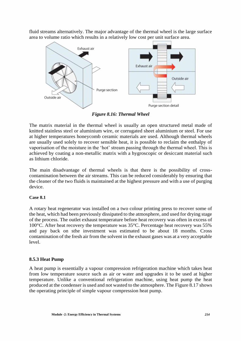
Module -2: Energy Efficiency in Thermal Systems 214
fluid streams alternatively. The major advantage of the thermal wheel is the large surface
area to volume ratio which results in a relatively low cost per unit surface area.
Figure 8.16: Thermal Wheel
The matrix material in the thermal wheel is usually an open structured metal made of
knitted stainless steel or aluminium wire, or corrugated sheet aluminium or steel. For use
at higher temperatures honeycomb ceramic materials are used. Although thermal wheels
are usually used solely to recover sensible heat, it is possible to reclaim the enthalpy of
vaporisation of the moisture in the ‘hot’ stream passing through the thermal wheel. This is
achieved by coating a non-metallic matrix with a hygroscopic or desiccant material such
as lithium chloride.
The main disadvantage of thermal wheels is that there is the possibility of cross-
contamination between the air streams. This can be reduced considerably by ensuring that
the cleaner of the two fluids is maintained at the highest pressure and with a use of purging
device.
Case 8.1
A rotary heat regenerator was installed on a two colour printing press to recover some of
the heat, which had been previously dissipated to the atmosphere, and used for drying stage
of the process. The outlet exhaust temperature before heat recovery was often in excess of
100°C. After heat recovery the temperature was 35°C. Percentage heat recovery was 55%
and pay back on sthe investment was estimated to be about 18 months. Cross
contamination of the fresh air from the solvent in the exhaust gases was at a very acceptable
level.
8.5.3 Heat Pump
A heat pump is essentially a vapour compression refrigeration machine which takes heat
from low temperature source such as air or water and upgrades it to be used at higher
temperature. Unlike a conventional refrigeration machine, using heat pump the heat
produced at the condenser is used and not wasted to the atmosphere. The Figure 8.17 shows
the operating principle of simple vapour compression heat pump.

Module -2: Energy Efficiency in Thermal Systems 215
Figure 8.17: Vapour Compression Heat Pump
The performance of the vapour compression refrigeration cycle is quantified by the
coefficient of performance (COP), which can be expressed as follows:
For a refrigeration machine: COPRef =Useful Refrigeration Output
Net Work Input
For a heat pump: COPHp =UsefulHeatRejectedCycle
NetWorkInput
Heat pumps are well suited to applications where the evaporating and condensing
temperatures are close together such as in the cases when recovering heat from exhaust air
in heating and air conditioning applications. As a result, heat pumps are often used in air
conditioning applications.
8.5.4 Heat Pipe
Heat pipes are devices which can transfer 1000 times more thermal energy than copper. It
can be used in traditionally difficult heat exchange environments such as high particulate
gases, dirty liquids, corrosive environments, low temperature gradients.
Heat pipe is basically a metal and metal alloy tube that is sealed on both ends and with an
internal wick or mesh along the interior of the pipe. The Heat Pipe comprises of three
elements – a sealed container, a capillary wick structure and a working fluid. The capillary
wick structure is integrally fabricated into the interior surface of the container tube and
sealed under vacuum. Thermal energy applied to the external surface of the heat pipe is in
equilibrium with its own vapour as the container tube is sealed under vacuum and causes
the working fluid near the surface to evaporate instantaneously. Vapour thus formed
absorbs the latent heat of vaporization and this part of the heat pipe becomes an evaporator
region. The vapour then travels to the other end the pipe where the thermal energy is
removed causing the vapour to condense into liquid again, thereby giving up the latent

Module -2: Energy Efficiency in Thermal Systems 216
heat of the condensation. This part of the heat pipe works as the condenser region. The
condensed liquid then flows back to the evaporated region. (Figure 8.18) is Heat pipe has
a working fluid within a vacuum and typical working fluids used include liquid nitrogen,
methanol, water, and sodium. The temperature range along with fluid type and compatible
metals tubes are given the table 8.3 below.
Table 8.3: Temperature Ranges for Heat-Transfer Fluids Used in Heat Pipes
Fluid Temperature range (°C) Compatible Metals
Nitrogen -180 to 80 Stainless steel
Ammonia -70 to 60 Nickel, Aluminum, Stainless
steel
Methanol -45 to 115 Nickel, Copper, Stainless steel
Water 5 to 215 Nickel, Copper
Mercury 190 to 535 Stainless steel
Sodium 510 to 870 Nickel, Stainless steel
Lithium 870 to 1480 Alloy of Niobium and Zirconium
Silver 1480 to 1980 Alloy of Tantalum and Tungsten
The performance (amount of heat that can be transferred) of a heat pipe is a function of its
length, diameter, wick structure, and overall shape. The larger the diameter, the more
power that can be transported, but longer the length, the less capable is the performance.
Figure 8.18: Heat Pipe
The heat pipes are used in following industrial applications:
a. Process to Space Heating:
The heat pipe heat exchanger transfers the thermal energy from process exhaust for
building heating. The preheated air can be blended if required. The requirement of
additional heating equipment to deliver heated make up air is drastically reduced or
eliminated.
b. Process to Process:
The heat pipe heat exchangers recover waste thermal energy from the process exhaust and
transfer this energy to the incoming process air. The incoming air thus become warm and
can be used for the same process/other processes and reduces process energy consumption.
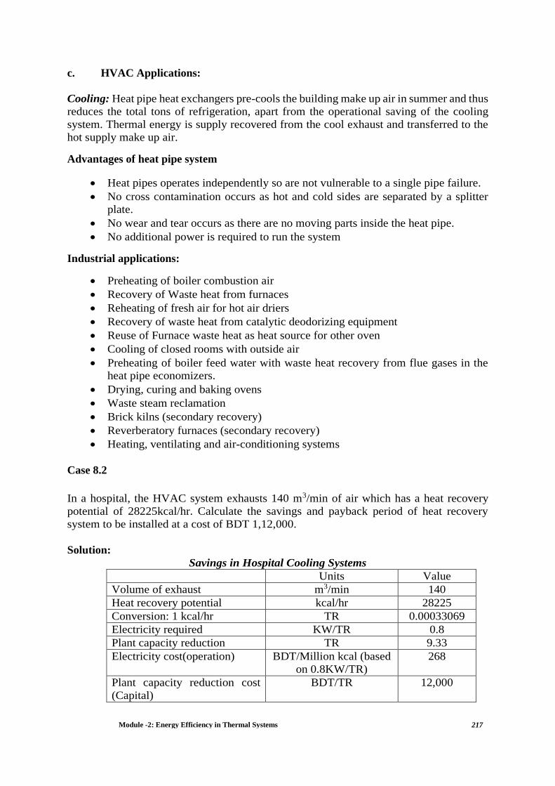
Module -2: Energy Efficiency in Thermal Systems 217
c. HVAC Applications:
Cooling: Heat pipe heat exchangers pre-cools the building make up air in summer and thus
reduces the total tons of refrigeration, apart from the operational saving of the cooling
system. Thermal energy is supply recovered from the cool exhaust and transferred to the
hot supply make up air.
Advantages of heat pipe system
Heat pipes operates independently so are not vulnerable to a single pipe failure.
No cross contamination occurs as hot and cold sides are separated by a splitter
plate.
No wear and tear occurs as there are no moving parts inside the heat pipe.
No additional power is required to run the system
Industrial applications:
Preheating of boiler combustion air
Recovery of Waste heat from furnaces
Reheating of fresh air for hot air driers
Recovery of waste heat from catalytic deodorizing equipment
Reuse of Furnace waste heat as heat source for other oven
Cooling of closed rooms with outside air
Preheating of boiler feed water with waste heat recovery from flue gases in the
heat pipe economizers.
Drying, curing and baking ovens
Waste steam reclamation
Brick kilns (secondary recovery)
Reverberatory furnaces (secondary recovery)
Heating, ventilating and air-conditioning systems
Case 8.2
In a hospital, the HVAC system exhausts 140 m3/min of air which has a heat recovery
potential of 28225kcal/hr. Calculate the savings and payback period of heat recovery
system to be installed at a cost of BDT 1,12,000.
Solution:
Savings in Hospital Cooling Systems
Units Value
Volume of exhaust m3/min 140
Heat recovery potential kcal/hr 28225
Conversion: 1 kcal/hr TR 0.00033069
Electricity required KW/TR 0.8
Plant capacity reduction TR 9.33
Electricity cost(operation) BDT/Million kcal (based
on 0.8KW/TR)
268
Plant capacity reduction cost
(Capital)
BDT/TR 12,000

Module -2: Energy Efficiency in Thermal Systems 218
Capital cost savings BDT 1,12,000/-
Payback period hours 16570
8.5.5 Thermo-compressor
In many cases, very low pressure steam are reused as water after condensation for lack of
any better option of reuse. In many cases it becomes feasible to compress this low pressure
steam by very high pressure steam and reuse it as a medium pressure steam. The major
energy in steam, is in its latent heat value and thus thermo compressing would give a large
improvement in waste heat recovery.
The thermo-compressor is a simple equipment with a nozzle where HP steam is accelerated
into a high velocity fluid. This entrains the LP steam by momentum transfer and then
recompresses in a divergent venturi. A figure of thermo-compressor is shown in Figure
8.19.
Figure 8.19: Thermo-compressor
It is typically used in evaporators where the boiling steam is recompressed and used as
heating steam
Case 8.3
Exhaust steam from evaporator in a fruit juice concentrator plant was condensed in a pre-
condenser operation on cooling water upstream of a steam jet vaccum ejector
Equipment Suggested Alt-1 Thermo compressor
Alt-2 shell & tube exchanger
Cost of thermo compressor BDT 1.5Lakhs
Savings of jacket steam due to
recompression of vapour
BDT 5.0 Lakhs per annum
Cost of shell &tube exchanger to pre
heat boiler feed water
BDT75,000/-
Savings in fuel cost BDT 4.5 Lakhs per annum
The recovery technologies for different heat source are given below
DISCHARGE
STEAM M.P
MOTIVE
DISCHARG E
STEAM H.P

Module -2: Energy Efficiency in Thermal Systems 219
Table 8.4: Waste of Heat Recovery Technologies for High range heat sources High range
Heat Source
Temperature
range (°C)
Recovery
method
Typical
uses
Type of
heat
exchanger
(Gas-Gas,
Gas-
Liquid)
Large
temperature
differentials
permitted
No Cross -
contaminati
on
Nickel
refining
furnace
1370 –1650 RR, CR 1 G-G x x
Aluminium
refining
furnace
650-760 CHW,CR,
WHB
1,2,3,5 G-G, G-L x x
Zinc refining
furnace
760-1100 RR, CR 1 G-G x x
Copper
refining
furnace
760- 815 CHW,CR,
WHB
1,2,3,5 G-G, G-L x x
Steel heating
furnaces
925-1050 RR, CR 1 G-G x x
Copper
reverberator
y furnace
900-1100 RR, CR 1 G-G x x
Open hearth
furnace
650-700 CHW,CR 1,2,3,5 G-G, G-L x x
Cement kiln
(Dry
process)
620- 730 CHW,CR 1,2,3,5 G-G, G-L x x
Glass
melting
furnace
1000-1550 RR, CR 1 G-G x x
Hydrogen
plants
650-1000 CHW,CR,
WHB
1,2,3,5 G-G, G-L x x
Solid waste
incinerators
650-1000 CHW,CR,
WHB
1,2,3,5 G-G, G-L x x
Fume
incinerators
650-1450 CHW,CR,
WHB
1,2,3,5 G-G, G-L x x
Recovery Methods
RR- Radiation Recuperator; CR - Convection Recuperetor; MHW - Metallic Heat
Wheel;CHW - Ceramic Heat Wheel WHB - Waste-heat Boilers
Typical Uses
1.Combustion air preheat 2. Space preheat 3. Boiler makeup water preheat 4. Boiler feed
water preheat
5. Domestic hot water 6. Hot water or steam generation. 7. Liquid feed flows requiring
heating
(Source: W. Turner Energy Management Handbook, 2007; Waste Heat Recovery:
Technology and Opportunities in U.S Industry,2008.)
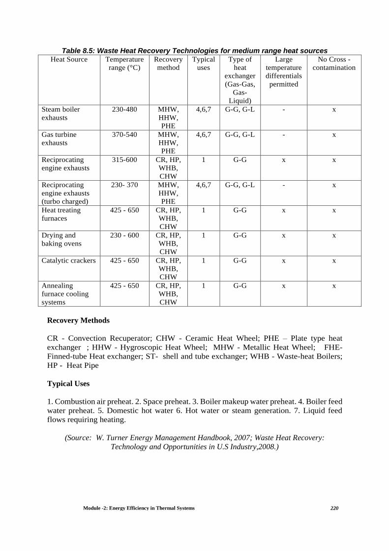
Module -2: Energy Efficiency in Thermal Systems 220
Table 8.5: Waste Heat Recovery Technologies for medium range heat sources
Heat Source Temperature
range (°C)
Recovery
method
Typical
uses
Type of
heat
exchanger
(Gas-Gas,
Gas-
Liquid)
Large
temperature
differentials
permitted
No Cross -
contamination
Steam boiler
exhausts
230-480 MHW,
HHW,
PHE
4,6,7 G-G, G-L - x
Gas turbine
exhausts
370-540 MHW,
HHW,
PHE
4,6,7 G-G, G-L - x
Reciprocating
engine exhausts
315-600 CR, HP,
WHB,
CHW
1 G-G x x
Reciprocating
engine exhausts
(turbo charged)
230- 370 MHW,
HHW,
PHE
4,6,7 G-G, G-L - x
Heat treating
furnaces
425 - 650 CR, HP,
WHB,
CHW
1 G-G x x
Drying and
baking ovens
230 - 600 CR, HP,
WHB,
CHW
1 G-G x x
Catalytic crackers 425 - 650 CR, HP,
WHB,
CHW
1 G-G x x
Annealing
furnace cooling
systems
425 - 650 CR, HP,
WHB,
CHW
1 G-G x x
Recovery Methods
CR - Convection Recuperator; CHW - Ceramic Heat Wheel; PHE – Plate type heat
exchanger ; HHW - Hygroscopic Heat Wheel; MHW - Metallic Heat Wheel; FHE-
Finned-tube Heat exchanger; ST- shell and tube exchanger; WHB - Waste-heat Boilers;
HP - Heat Pipe
Typical Uses
1. Combustion air preheat. 2. Space preheat. 3. Boiler makeup water preheat. 4. Boiler feed
water preheat. 5. Domestic hot water 6. Hot water or steam generation. 7. Liquid feed
flows requiring heating.
(Source: W. Turner Energy Management Handbook, 2007; Waste Heat Recovery:
Technology and Opportunities in U.S Industry,2008.)

Module -2: Energy Efficiency in Thermal Systems 221
Table 8.6: Waste Heat Recovery Technologies for low range heat sources
Heat Source Temperature
range (°C)
Recovery
method
Typical
uses
Type of
heat
exchanger
(Gas-Gas,
Gas-
Liquid)
Large
temperature
differentials
permitted
No Cross -
contamination
Process steam
condensate
55-88 PHE,MHW,
HHW
2 G-L - x
Cooling water
from:
Furnace doors 32-55 PHE,MHW,
HHW
2 G-L - x
Bearings,
Welding
machines,
Injection
molding
machines.
32-88 PHE,MHW,
HHW
2 G-L - x
Annealing
furnaces
66-230 FHE, WHB,
ST
3,6,7 G-G,G-L x x
Forming dies,
pumps
27-88 PHE,MHW,
HHW
2 G-L - x
Air
compressors
27-50 PHE,MHW,
HHW
2 G-L - x
Air
conditioning
and
refrigeration
condensers
32–43 PHE,MHW,
HHW
2 G-L - x
Drying,
baking and
curing ovens
93-230 FHE, WHB,
ST
2 G-L x
Hot processed
liquids
32-232 FHE, WHB,
ST
3,6,7 G-G,G-L x x
Recovery Methods
MHW - Metallic Heat Wheel; HHW - Hygroscopic Heat Wheel; PHE – Plate type heat
exchanger ; FHE Finned-tube Heat exchanger; ST- Shell and tube exchanger; WHB -
Waste-heat Boilers.
Typical Uses
1. Combustion air preheat. 2. Space preheat. 3. Boiler makeup water preheat. 4. Boiler feed
water pre heat. 5. Domestic hot water. 6. Hot water or steam generation. 7. Liquid feed
flows requiring heating.
(Source: W. Turner Energy Management Handbook, 2007;Waste Heat Recovery:
Technology and Opportunities in U.S. Industry,2008)

Module -2: Energy Efficiency in Thermal Systems 222
8.6 Heat exchanger configurations
The two most commonly used heat exchanger flow configurations are counter flow and
parallel flow. These flow patterns are represented in Figures 8.20 and 8.21 respectively,
along with their characteristic temperature profiles.
Figure 8.20: Counter Flow Heat Exchanger
Figure 8.21: Parallel Flow Heat Exchanger
It should be noted that with the parallel flow configuration the ‘hot’ stream is always
warmer than the ‘cold’ stream. With the counter flow configuration it is possible for the
outlet temperature of the cold fluid to be higher than the outlet temperature of the hot fluid.
The general equations which govern the heat transfer in recuperative heat exchangers are
as follows:
Q = mhCh(th.in − th.out) = mcCc(tc.in − tc.out)
and
Q = U Ao(LMTD)K Where,
Q is the rate of heat transfer (W),
mh is the mass flow rate of hot fluid (kg/s),
mc is the mass flow rate of cold fluid (kg/s),
Ch is the specific heat of hot fluid (J/kgK),
Cc is the specific heat of cold fluid (J/kgK),
th,in and th,out are the inlet and outlet temperatures of hot fluid
tc,inand tc,out are the inlet and outlet temperatures of cold fluid

Module -2: Energy Efficiency in Thermal Systems 223
U is the overall heat transfer coefficient (i.e. U value) (W/m2K),
Ao is the outside surface area of heat exchanger (m2),
LMTD is the logarithmic mean temperature difference
K is the constant which is dependent on the type of flow through the heat exchanger
(K = 1 for counter-flow and parallel flow, and is therefore often ignored).
The logarithmic mean temperature difference (LMTD) can be determined by:
LMTD = ∆T1 − ∆T2
ln( ∆T1/∆T2)
where,
∆𝑻𝟏 = 𝒕𝒉.𝒊𝒏 − 𝒕𝒄.𝒐𝒖𝒕 and ∆𝑻𝟐 = 𝒕𝒉.𝒐𝒖𝒕 − 𝒕𝒄.𝒊𝒏for Counter Flow Heat Exchanger
∆𝑻𝟏 = 𝒕𝒉.𝒊𝒏 − 𝒕𝒄.𝒊𝒏 and ∆𝑻𝟐 = 𝒕𝒉.𝒐𝒖𝒕 − 𝒕𝒄.𝒐𝒖𝒕for Parallel Flow Heat Exchanger
Case 8.4: Heat recovery from heat treatment furnace
In a heat treatment furnace, the exhaust gases are leaving the furnace at 900oC at the rate
of 2100 m3/hour. The total heat recoverable at 180oC final exhaust can be calculated as
𝑸 = 𝑽 × 𝝆 × 𝑪𝒑 × ∆𝑻
Q is the heat content in kCal
V is the flow rate of the substance in m3/hr
ρ is density of the flue gas in kg/m3
Cp is the specific heat of the substance in kCal/kg °C
∆T is the temperature difference in °C
Cp (Specific heat of flue gas) = 0.24 kCal/kg/°C
Heat available (Q) = 2100 x 1.19 x 0.24 x (900-180) = 4,31,827 kCal/hr
By installing a recuperator, this heat can be recovered to pre-heat the combustion air. The
fuel savings would be 33% (@ 1% fuel reduction for every 22°C reduction in temperature
of flue gas.
8.7 Heat Transfer Augmentation
Principles of heat transfer for waste heat recovery are similar to any heat exchange
mechanisms. To promote the heat transfer co-efficient h, three different methods are used.
They are
Active method
Passive Method
Combined active and passive method
Active Method employs supplementary power supply. Passive method includes twisted
tapes, ribbons, wire coils, indentation of heat transfer surface, etc. to break the thermal
boundary layer to promote the heat transfer coefficient. In some cases, both the active and
passive methods may be combined to promote the heat transfer coefficient.