MODULE 14a: FOT-OSP OPTICAL FIBER MEASUREMENT & …
49
1 MODULE 14a: FOT-OSP OPTICAL FIBER MEASUREMENT & TESTING
Transcript of MODULE 14a: FOT-OSP OPTICAL FIBER MEASUREMENT & …

1
MODULE 14a:FOT-OSP OPTICAL FIBER MEASUREMENT & TESTING

2
MODULE 14a:FOI OPTICAL FIBER MEASUREMENT &
TESTING

14.1 Explain why test equipment calibration should be traceable to the National
Institute of Standards and Technology (NIST ) calibration standard.
3

The routine calibration of test equipment is essential to achieving accurate test results. Calibration is always required for test equipment that makes absolute measurements, such as an optical power meter.
19
FOI 14.1 Explain why test equipment calibration should be
traceable to the National Institute of Standardsand Technology
(NIST ) calibration standard.

Optical power meters should be calibrated to the three principal wavelength regions:850nm1300nm1550nm
20
FOI 14.1 Explain why test equipment calibration should be traceable to the
National Institute of Standardsand Technology (NIST ) calibration standard.

Calibration should be traceable to the National Institute of Standards and Technology (NIST) calibration standard or some other standard.A calibration sticker should be clearly visible and not expired.
21
FOI 14.1 Explain why test equipment calibration should be traceable to the
National Institute of Standardsand Technology (NIST ) calibration standard.

Calibration sticker on a piece of test equipment
22
FOI 14.1 Explain why test equipment calibration should be
traceable to the National Institute of Standardsand Technology
(NIST ) calibration standard.
Return to
menu

14.2 Describe the types of fiber optic test equipment that can be used to test for continuity.
4

It is a basic and essential tool for every fiber-optic toolkit.It is also one of the least expensive tools in your toolkit.It will allow you to quickly verify the continuity of an optical fiber.They are typically just a modified flashlight.
23
14.2 Describe the types of fiber optic test equipment thatcan be used to test for continuity

Can locate faults within the OTDR's deadzone
Dead Zone

OSP When performing a mid-entry (aka: express entry) into a cable span, or to determine which fibers are active in a slice enclosure, a Fiber Identifier determines whether the fiber is carrying traffic?
24
Pages 837-839

14.3 Explain the use of a visual fault locator (VFL) when troubleshooting a fiber span.
5

Can locate faults within the OTDR's deadzone
Dead Zone

Fills the core of the optical fiber with light from the laser.
28Pages 834-836
The light from the laser escapes the optical fiber at a break or macrobend.and will typically illuminate the buffer surrounding the optical fiber.
14.3 Explain the use of a visual fault locator (VFL) when troubleshooting a fiber span.

The light from a VFL identifies a broken ferrule in a multifiber connector
25Pages 834-836

The light from a VFL identifying a macrobend in simplex cordage.
27Pages
14.3 Explain the use of a visual fault locator (VFL) when troubleshooting a fiber span.

14.4 Describe the basic operation of a multimode and single-
mode optical loss test set (OLTS)
6

Multimode OLTSAvailable with either a VCSEL or an LED light source.
36Pages 840-843
14.5 Describe the basic operation of a single-mode and a multimode light source and optical power meter

They work hand in hand with each other.They are typically referred to as an optical loss test set (OLTS). 14.4 Describe the basic operation of a multimode and single-mode optical loss test set (OLTS)
37Pages
14.4 Describe the basic operation of a multimode and single-mode optical loss test set (OLTS)

Multimode OLTSAvailable with either a VCSEL or an LED light source.
39
Pages
Normally an LED Light source used to test multimode Enterprise Networks
14.4 Describe the basic operation of a multimode and single-mode optical loss test set (OLTS)

Both singlemode and multimode light sources must be stable to make accurate end to end loss measurements
FOI14.4 Describe the basic operation of a multimode and single-mode

Important Note:Never disconnect and reconnect a reference jumper from the Light source during testing. The insertion loss change of the coupling each time is mated will change even slightly. This will ter your reference value and effect your measurement.Set your power meter to NOT time out during extensive testing. You will
have to re–zero or re-reference your equipment. (could be a long walk)
42Pages 850-851

14.5 the difference between a patch cord and a measurement quality jumper (MQJ)
.
7

ANSI/TIA-568-C.3, section 6 sets the performance specifications for optical fiber patch cords recognized in premises cabling standards.It is used:
At cross-connections to connect optical fiber linksAs equipment or work area cords to connect telecommunications equipment to horizontal or backbone cabling
46
Pages 843-844

It is a length of optical fiber cable with connectors on both ends.It uses the ssame connector type and ooptical fiber type as the optical fiber cabling that it is connected to.
47
Pages4
SM ST-ST UPC SM SC-SC UPC MM 62.5/125um LC/PC-LC/PC
LC MM 50um OM3
FOI14.5 Explain the difference between a patch cord and a
measurement quality jumper (MQJ)

The terms patch cord and jumper are often interchanged.A test jumper can be a single-fiber cable or a multifiber cable.Test jumpers as described in ANSI/TIA-526-14-A.
48
Pages 843-844
May have several namesTransmit jumper
Connects to the light sourceReceive jumperConnects to the optical power meter
Measurement quality jumper (MQJ)U.S. Navy test jumper
Reference jumperAnother name for a test jumper
…a man has no name

They must have a core diameter and numerical aperture nominally equal to the optical fiber being tested.They should be cleaned and inspected prior to making measurements.They should be tested for insertion loss prior to performing any of the ANSI/TIA-526-14-A methods.They should be treated with care, especially multiple fiber Measurement Quality Jumpers (MQJs).
49
Pages 843-844

14.6 Define the purpose of a mode filter.
8

Transmit test jumper with mandrel wrap
Pages 845-846
Why?

Page_______Module / Chapter ________

LED Detector
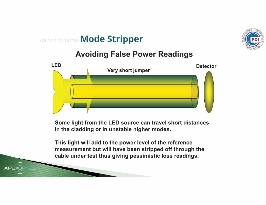
FOI OSP Mode Filter
LED Detector
Some light from the LED source can travel short distances in the cladding or in unstable higher modes.
This light will add to the power level of the reference measurement but will have been stripped off through the cable under test thus giving pessimistic loss readings.
Avoiding False Power Readings
Very short jumper

An LED with a mandrel wrap used to test multimode Enterprise Networks normally use what type of electro-optical component
LED with a mandrel wrap
LED
Presented by Apex Optics Inc. Text box
Page__479 mod 14.29

14.7 Explain why five small-radius nonoverlapping loops around a mandrel may be required on
the transmit jumper when measuring multimode link attenuation in accordance with ANSI/TIA-
526-14-A
9


14.8 Explain why a single turn 30mm in diameter loop must be applied to the transmit
jumper when measuring single-mode link attenuation in accordance with ANSI/TIA-526-7
10


14.9 Explain why the encircled flux requirement was developed for multimode link
attenuation measurements.
11

Encircled Flux test launch condition is the most accurate for determining attenuation measurements for high speed systems using VCSEL light sources over multimode fibers?

14.10 Explain why multimode insertion loss measurements being performed in
accordance with ANSI/TIA-526-14- require a modal controller on the transmit jumper
12

LED Detector
Some light from the LED source can travel short distances in the cladding or in unstable higher modes.
This light will add to the power level of the reference measurement but will have been stripped off through the cable under test thus giving pessimistic loss readings.
Avoiding False Power Readings
Very short jumper

14.11 Describe how to measure the optical loss in a patch cord with an OLTS using the
steps described in ANSI/TIA-526-14, method A, two-test jumper reference
13

Page_______Module / Chapter ________

14.12 Summarize the basic operation of an optical time domain reflectometer (OTDR)
14

The Optical Time-Domain Reflectometer (OTDR) can be used to evaluate the loss and reflectance of interconnections and splices.It will measure the attenuation rate of an optical fiber and locate faults.
17Pages 850-851

Fiber Optic Testing and Troubleshooting
What type of testing is done with an OTDR (Optical Time Domain
Reflectometer)?
Tier 2 testing is performed with an Optical time Domain Reflectometer (OTDR), which provides more detailed information as compared to Tier 1 testing performed with an OLTS
An OTDR provides a visual trace of the fiber cable from where we can extract the following information…
OTDR

FOI 14.13 Describe the required Tier 1 Testing tasks and equipment
15

14.14 Describe the required Tier 2 Testing tasks and equipment
16

Fiber Optic Testing and Troubleshooting
What type of testing is done with an OTDR (Optical Time Domain
Reflectometer)?
Tier 2 testing is performed with an Optical time Domain Reflectometer (OTDR), which provides more detailed information as compared to Tier 1 testing performed with an OLTS
An OTDR provides a visual trace of the fiber cable from where we can extract the following information…
OTDR


![[Challenge:Future] FOT Gang](https://static.fdocuments.net/doc/165x107/58f322a91a28ab7e6e8b462b/challengefuture-fot-gang.jpg)