Modification of a ball diameter-measuring instrument for NMi · Modification of a ball...
22
Modification of a ball diameter-measuring instrument for NMi R.J. Jenneskens DCT 2006.059 Report short internship Startdate: Monday, March 27th 2006 Enddate: Tuesday, May 30th 2006 Rob Jenneskens (R.J.), studentnr. 501016 Supervisor TU/e: P.C.J.N. Rosielle Supervisor NMi: G.J. Kotte Section Control Systems Technology, TU/e Prof.dr.ir. Maarten Steinbuch
Transcript of Modification of a ball diameter-measuring instrument for NMi · Modification of a ball...
Modification of a balldiameter-measuringinstrument for NMi
R.J. Jenneskens
DCT 2006.059
Report short internshipStartdate: Monday, March 27th 2006Enddate: Tuesday, May 30th 2006
Rob Jenneskens (R.J.), studentnr. 501016
Supervisor TU/e: P.C.J.N. RosielleSupervisor NMi: G.J. Kotte
Section Control Systems Technology, TU/eProf.dr.ir. Maarten Steinbuch

Contents
1 Introduction 2
2 Current Design 32.1 Measurement principle . . . . . . . . . . . . . . . . . . . . . . . . . . . . . . . 32.2 Disadvantages . . . . . . . . . . . . . . . . . . . . . . . . . . . . . . . . . . . . 4
3 Design Requirements 5
4 Design Aspects 64.1 Base frame . . . . . . . . . . . . . . . . . . . . . . . . . . . . . . . . . . . . . 64.2 Mirror . . . . . . . . . . . . . . . . . . . . . . . . . . . . . . . . . . . . . . . . 74.3 Gauge block . . . . . . . . . . . . . . . . . . . . . . . . . . . . . . . . . . . . . 84.4 Force application . . . . . . . . . . . . . . . . . . . . . . . . . . . . . . . . . . 94.5 Force measurement . . . . . . . . . . . . . . . . . . . . . . . . . . . . . . . . . 124.6 Stroke . . . . . . . . . . . . . . . . . . . . . . . . . . . . . . . . . . . . . . . . 144.7 Temperature chamber . . . . . . . . . . . . . . . . . . . . . . . . . . . . . . . 144.8 Ball placement . . . . . . . . . . . . . . . . . . . . . . . . . . . . . . . . . . . 15
5 Concept 16
6 Conclusions and Recommendations 17
Bibliography 18
A Finite element results 19
B Piezo Tip (PI P-250) 20
C Motor Mike (PI M-227) 21
1
Chapter 1
Introduction
In current industry, precision balls are used in many applications, such as bearings and probetips. To improve accuracy of machinery, stiffer bearings are required. Bearing stiffness isincreased by pre-loading the balls in the bearing. This can only be done, when the exactgeometry of each ball is known and within a specific range. Moreover, in dimensional metrol-ogy, balls are used as probe tips. As one can imagine, the exact geometry of the probe tiphas to be known to achieve reliable measurements.
The Van Swinden Laboratorium, part of the National Metrology Institute of The Netherlands(NMi), has developed a ball diameter-measuring instrument [2]. The measurement principleis based on gauge block measurement using interferometry and will be explained in chapter2. The disadvantages of the current design, reported by NMi, are mentioned resulting in thedesign requirements for a new ball diameter measurement instrument in chapter 3. In chap-ter 4 the instrument is divided in main parts and functionalities. These main design aspectsare treated and different solutions are presented for each aspect. In chapter 5 a concept isproposed which is automated so operating costs of the instrument will reduce substantially.
2
Chapter 2
Current Design
2.1 Measurement principle
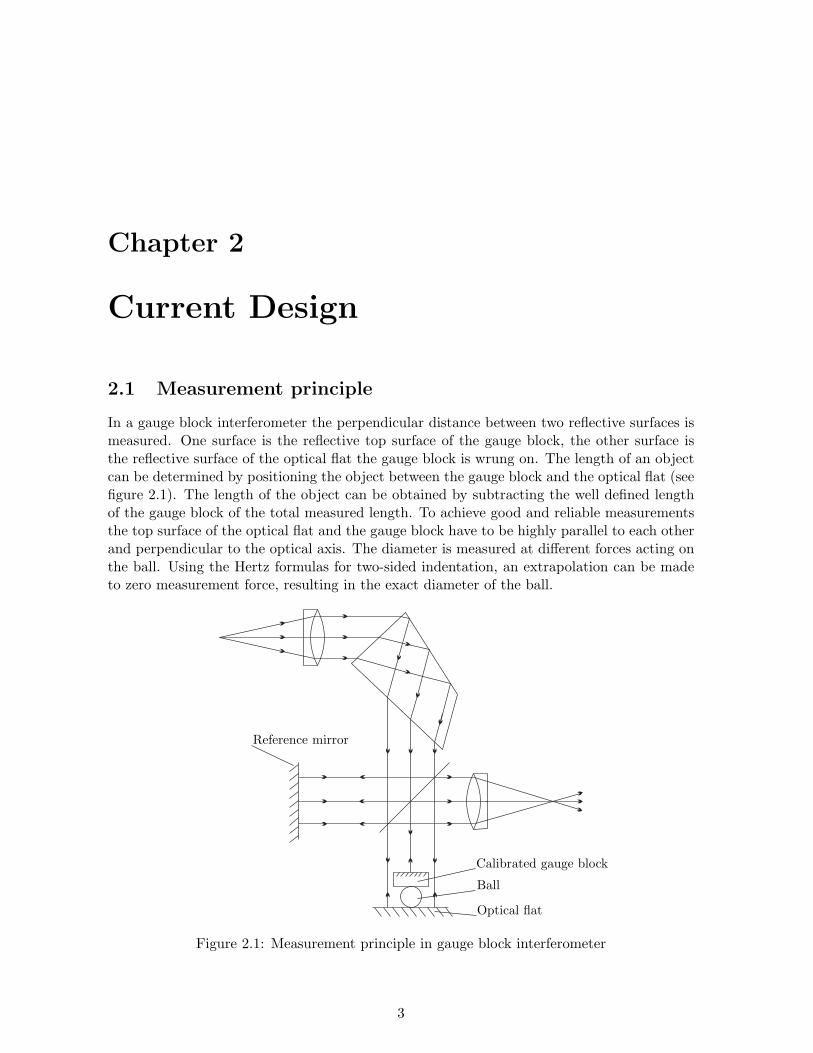
In a gauge block interferometer the perpendicular distance between two reflective surfaces ismeasured. One surface is the reflective top surface of the gauge block, the other surface isthe reflective surface of the optical flat the gauge block is wrung on. The length of an objectcan be determined by positioning the object between the gauge block and the optical flat (seefigure 2.1). The length of the object can be obtained by subtracting the well defined lengthof the gauge block of the total measured length. To achieve good and reliable measurementsthe top surface of the optical flat and the gauge block have to be highly parallel to each otherand perpendicular to the optical axis. The diameter is measured at different forces acting onthe ball. Using the Hertz formulas for two-sided indentation, an extrapolation can be madeto zero measurement force, resulting in the exact diameter of the ball.
Reference mirror
Calibrated gauge block
Ball
Optical flat
Figure 2.1: Measurement principle in gauge block interferometer
3
CHAPTER 2. CURRENT DESIGN 4
2.2 Disadvantages
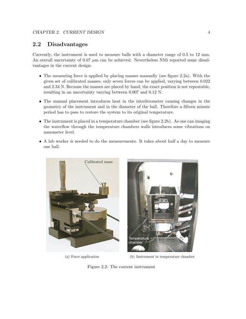
Currently, the instrument is used to measure balls with a diameter range of 0.5 to 12 mm.An overall uncertainty of 0.07 µm can be achieved. Nevertheless NMi reported some disad-vantages in the current design:
• The measuring force is applied by placing masses manually (see figure 2.2a). With thegiven set of calibrated masses, only seven forces can be applied, varying between 0.022and 2.34 N. Because the masses are placed by hand, the exact position is not repeatable,resulting in an uncertainty varying between 0.007 and 0.12 N.
• The manual placement introduces heat in the interferometer causing changes in thegeometry of the instrument and in the diameter of the ball. Therefore a fifteen minuteperiod has to pass to restore the system to its original temperature.
• The instrument is placed in a temperature chamber (see figure 2.2b). As one can imagingthe waterflow through the temperature chambers walls introduces some vibrations onnanometer level.
• A lab worker is needed to do the measurements. It takes about half a day to measureone ball.
Calibrated mass
(a) Force application
Temperaturechamber
(b) Instrument in temperature chamber
Figure 2.2: The current instrument
Chapter 3
Design Requirements
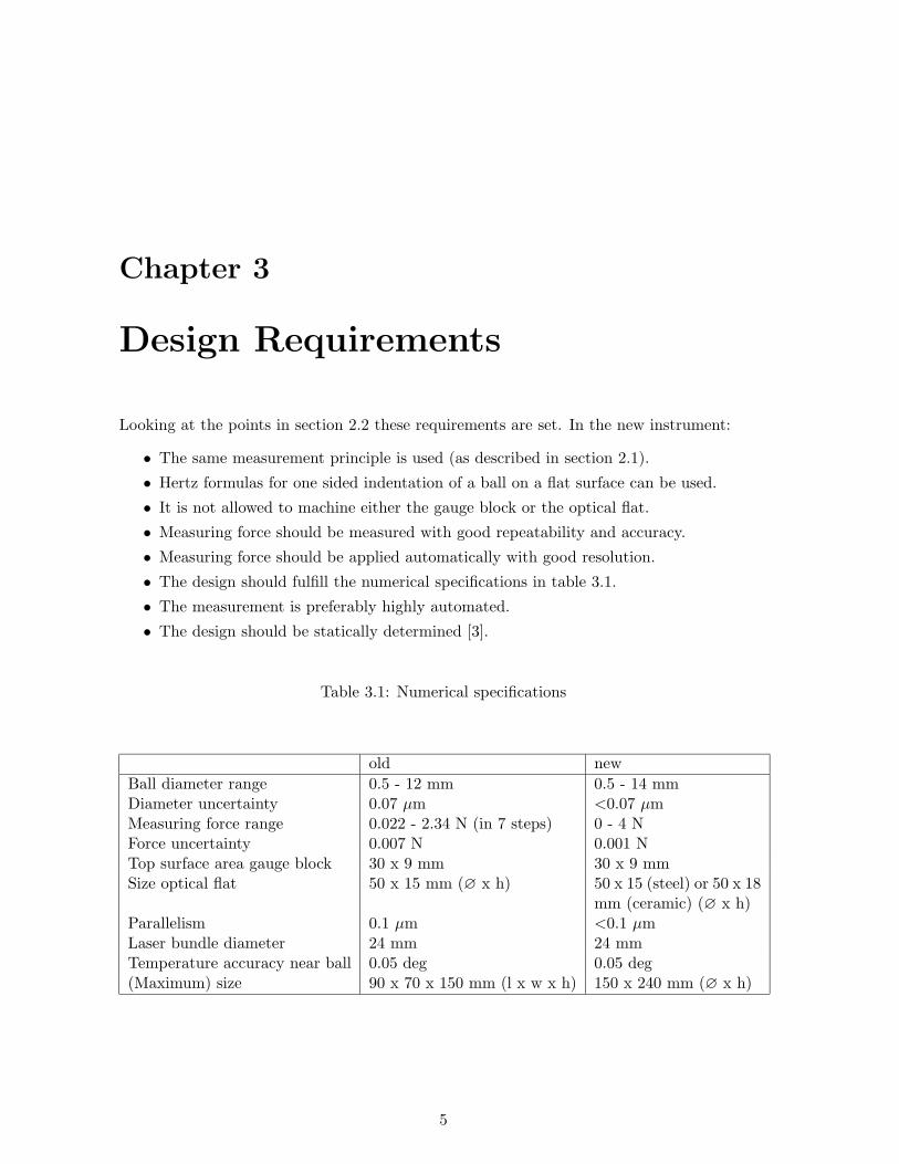
Looking at the points in section 2.2 these requirements are set. In the new instrument:
• The same measurement principle is used (as described in section 2.1).
• Hertz formulas for one sided indentation of a ball on a flat surface can be used.
• It is not allowed to machine either the gauge block or the optical flat.
• Measuring force should be measured with good repeatability and accuracy.
• Measuring force should be applied automatically with good resolution.
• The design should fulfill the numerical specifications in table 3.1.
• The measurement is preferably highly automated.
• The design should be statically determined [3].
Table 3.1: Numerical specifications
old new
Ball diameter range 0.5 - 12 mm 0.5 - 14 mmDiameter uncertainty 0.07 µm <0.07 µmMeasuring force range 0.022 - 2.34 N (in 7 steps) 0 - 4 NForce uncertainty 0.007 N 0.001 NTop surface area gauge block 30 x 9 mm 30 x 9 mmSize optical flat 50 x 15 mm (∅ x h) 50 x 15 (steel) or 50 x 18
mm (ceramic) (∅ x h)Parallelism 0.1 µm <0.1 µmLaser bundle diameter 24 mm 24 mmTemperature accuracy near ball 0.05 deg 0.05 deg(Maximum) size 90 x 70 x 150 mm (l x w x h) 150 x 240 mm (∅ x h)
5

Chapter 4
Design Aspects
4.1 Base frame
As base of the design a stiff frame is required. It is placed on three feet on the tilting tableof the interferometer (see figure 4.1a). These feet can be spherical contacts, and are placedas wide apart as possible for good stability and rotation stiffness around the x- and y-axis(see figure 4.1b). In figures in this chapter the base frame will be schematically representedas ”fixed world”. When all components are placed on the fixed world correctly, they will bealigned correctly. By manipulating the tilting table all relevant components can be positionedperpendicular to the optical axis. By sliding the base frame on the tilting table in the xy-plane the components can be aligned with the optical axis. When the overall concept and allcomponents are chosen the base frame can be designed.
Tilting table
(a) Instrument on tilting table
x
y
z
ϕ
ψ
θ
(b) The 6 degrees of freedom (DOF)
Figure 4.1: Tilting table and used coordinate system
6
CHAPTER 4. DESIGN ASPECTS 7
4.2 Mirror
The optical flat on which the ball is placed is either a steel or a ceramic cylindrical mirror.Its dimensions are 50 mm in diameter and 15 mm or 18 mm in height for steel and ceramic,respectively. The mirror is flat within 0.05 µm. It should be easy to replace the mirror to beable to measure steel and ceramic balls on the same instrument.
Because the diameter of the mirror is 50 mm and the diameter of the laser bundle is 24mm the x and y positioning of the mirror does not have to be very accurate. Rotationalsymmetry makes θ unimportant. Because interferometry is a relative measurement principlez is also irrelevant. The important DOFs are ϕ and ψ. To achieve high rotational stiffness themirror can be placed on the instrument either on a rubber surface or statically determined onthree points. Because the thickness of a rubber slab can not be produced with high accuracyit is chosen to place the mirror on three spherical contacts. Two different configurations areconsidered for placing the mirror on three points:
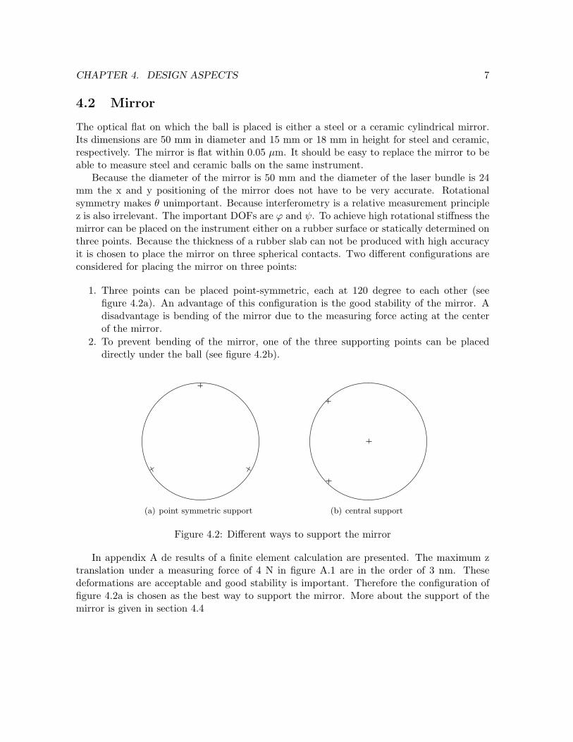
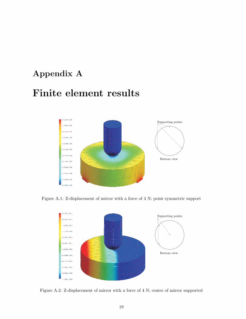
1. Three points can be placed point-symmetric, each at 120 degree to each other (seefigure 4.2a). An advantage of this configuration is the good stability of the mirror. Adisadvantage is bending of the mirror due to the measuring force acting at the centerof the mirror.
2. To prevent bending of the mirror, one of the three supporting points can be placeddirectly under the ball (see figure 4.2b).
(a) point symmetric support (b) central support
Figure 4.2: Different ways to support the mirror
In appendix A de results of a finite element calculation are presented. The maximum ztranslation under a measuring force of 4 N in figure A.1 are in the order of 3 nm. Thesedeformations are acceptable and good stability is important. Therefore the configuration offigure 4.2a is chosen as the best way to support the mirror. More about the support of themirror is given in section 4.4

CHAPTER 4. DESIGN ASPECTS 8
4.3 Gauge block
The dimensions of the currently used gauge block are 30 x 9 x 5 mm (l x w x h). Thegauge block is taken from a set in which all gauges have the same top surface of 30 x 9 mm.Bending of the gauge block has been calculated analytically. The central deflection s of asimply supported beam with length L, under a force F at the middle of the beam is calculatedby [1]:
s = −FL3
48EI(4.1)
with I the second moment of inertia of a rectangular cross-section:
I =wh3
12(4.2)
Measuring a steel ball (E = 205 GPa) with a measuring force of 2.35 N (which is thecurrent maximum measurement force) results in a maximum deflection at the center of thegauge block of 70 nm. This seems unreasonably high. Looking at equation 4.1, bending of thegauge block can be decreased by either changing the material (E) or changing the geometry(I) of the gauge block.
As we can see in table 4.1 tungsten-carbide has good characteristics for a gauge block(high stiffness and low thermal expansion). Choosing another gauge block material has thedisadvantage that the Hertz formulas have to be reviewed, because they are derived for contactbetween two objects of the same material.
Table 4.1: Gauge block material characteristics
Material E [Gpa] Thermal Expansion [x 10−6K−1]
Steel 205 11±1Ceramic 205 9.7Tungsten-Carbide 600 4.23
CHAPTER 4. DESIGN ASPECTS 9
Looking at equation 4.2 we can see that the stiffness of a beam increases with the thirdpower of its height. Increasing the height of the gauge block with a factor 3 (from 5 to 15mm) will result in a factor 33 = 27 reduction in bending. Thereby the deflection is decreasedto 2.6 nm, which is in the same order as bending of the optical flat. When the force increasesfrom 2.35 to 4 N the deflection (4.4 nm) is still acceptable. Moreover the assumption thatthe gauge block can be seen as an infinite halfplane is more valid.The best way to mount the gauge block is to fix it to the frame. This gives two advantages:
1. When the gauge block is fixed to the frame, and is tilted perpendicular to the opticalaxis using the interferometry image, the complete instrument will be well oriented.
2. When the gauge block is rigidly attached to the base frame, gravitational forces on thegauge block will not influence the measuring force range.
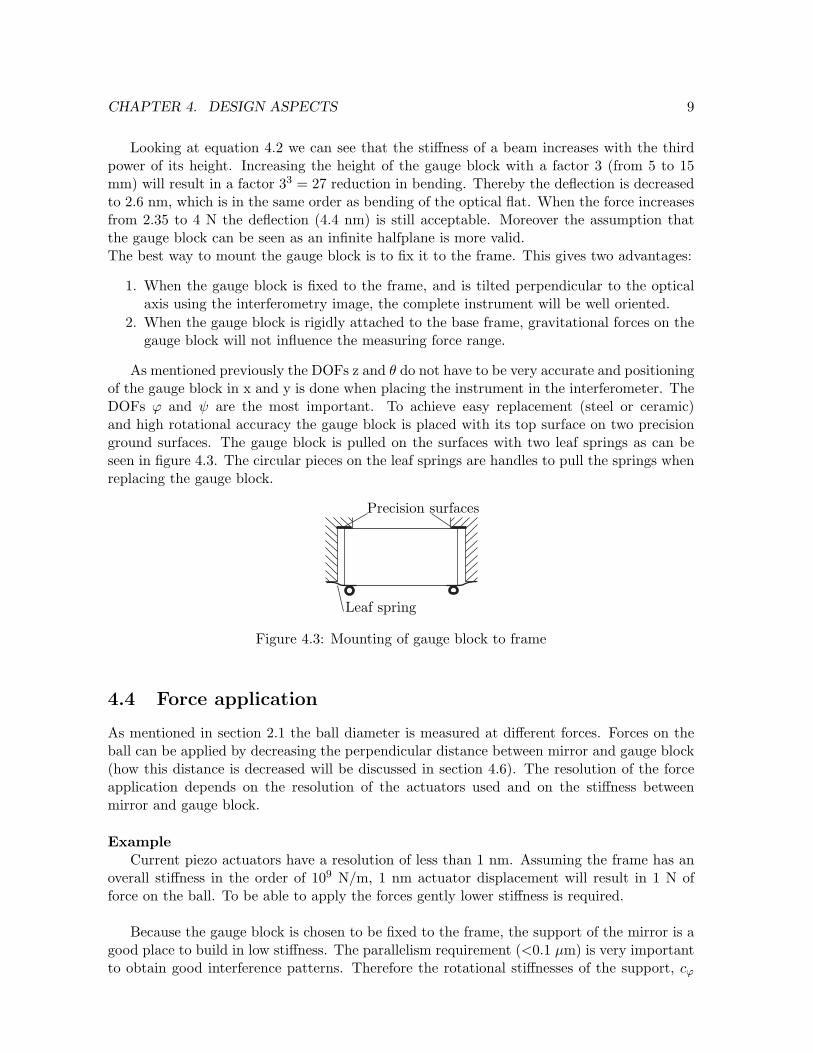
As mentioned previously the DOFs z and θ do not have to be very accurate and positioningof the gauge block in x and y is done when placing the instrument in the interferometer. TheDOFs ϕ and ψ are the most important. To achieve easy replacement (steel or ceramic)and high rotational accuracy the gauge block is placed with its top surface on two precisionground surfaces. The gauge block is pulled on the surfaces with two leaf springs as can beseen in figure 4.3. The circular pieces on the leaf springs are handles to pull the springs whenreplacing the gauge block.
Precision surfaces
Leaf spring
Figure 4.3: Mounting of gauge block to frame
4.4 Force application
As mentioned in section 2.1 the ball diameter is measured at different forces. Forces on theball can be applied by decreasing the perpendicular distance between mirror and gauge block(how this distance is decreased will be discussed in section 4.6). The resolution of the forceapplication depends on the resolution of the actuators used and on the stiffness betweenmirror and gauge block.
ExampleCurrent piezo actuators have a resolution of less than 1 nm. Assuming the frame has an
overall stiffness in the order of 109 N/m, 1 nm actuator displacement will result in 1 N offorce on the ball. To be able to apply the forces gently lower stiffness is required.
Because the gauge block is chosen to be fixed to the frame, the support of the mirror is agood place to build in low stiffness. The parallelism requirement (<0.1 µm) is very importantto obtain good interference patterns. Therefore the rotational stiffnesses of the support, cϕ

CHAPTER 4. DESIGN ASPECTS 10
and cψ, should be high. The only way to achieve high stiffness in ϕ and ψ in combinationwith low stiffness in z is a translational guiding. Such a guiding can be realized with rolling,sliding or elastic elements. Elastic elements are commonly used in precision instruments.Due to their absence of friction and thereby low hysteresis, high accuracy is achievable overtime. Two examples of such guidings are given in figure 4.4. Figure 4.4a shows a rotationalsymmetric, radially supported, linear guiding. Figure 4.4b shows a double parallellogramlinear guiding.
A rotational symmetric guiding is chosen. Rotational symmetry of the guiding will in-troduce the same stiffness in all directions in the xy-plane, thereby eliminating unwantedrotations of that plane. Moreover, the mirror has a round top surface, so the guiding fits un-der it, and a compact design can be made. The guiding is equipped with folded leaf springs.The folded parts of the leaf springs compensate for the shortening of the guiding parts. Sucha guiding can be produced out of one piece of aluminium using electrical discharge machining(EDM). The advantage of such a monolith is that there are no mountings introducing hys-teresis. Also the thermal center of the guiding lies on the optical axis.
To be able to design a guiding the desired stiffnesses cz, cϕ and cψ have to be known. A forcerange of 0 to 4 N with a force application resolution of 0.001 N is desired. This results in4000 steps, and thus in a travel range of the piezo actuator (resolution 1 nm) of 4µm. Themaximum axial stiffness between gauge block and mirror is then: cz = 4N
4·10−6m= 1·106 N/m
= 1 N/µm. It is preferable to decrease this stiffness, e.g. with a factor of ten, to gain in forceapplication resolution. The stiffnesses cϕ and cψ should be at least 1000 times higher.
In figure 4.5 two concepts are presented of how to construct the mirror support. In figure4.5a the dimensions of the folded leaf springs determine cz. Actuator resolution has to beknown before producing the guiding. In figure 4.5b an extra coiled spring has been build in.The folded leaf springs (together) have to be at least 100 times less stiff in axial directionthan the coiled spring. Thereby cz is determined by the axial stiffness of the coiled spring.The spring can be replaced if necessary (e.g. for small ball diameters or when actuators arereplaced).
In the next sections the force measurement system will be integrated in the mirror support.Also the actuators for applying force and for realizing the stroke are integrated in the design.

CHAPTER 4. DESIGN ASPECTS 11
(a) Radially supported guiding (b) Double parallelogram guiding
Figure 4.4: Two types of elastic linear guidings
Mirror
Folded leaf spring
Mirror support
Translating body
(a) Leaf springs determine cz
Coiled spring
(b) Coiled spring determines cz
Figure 4.5: Mirror support with low cz and high cϕ and cψ
CHAPTER 4. DESIGN ASPECTS 12
4.5 Force measurement
There are three ways to measure the applied force:
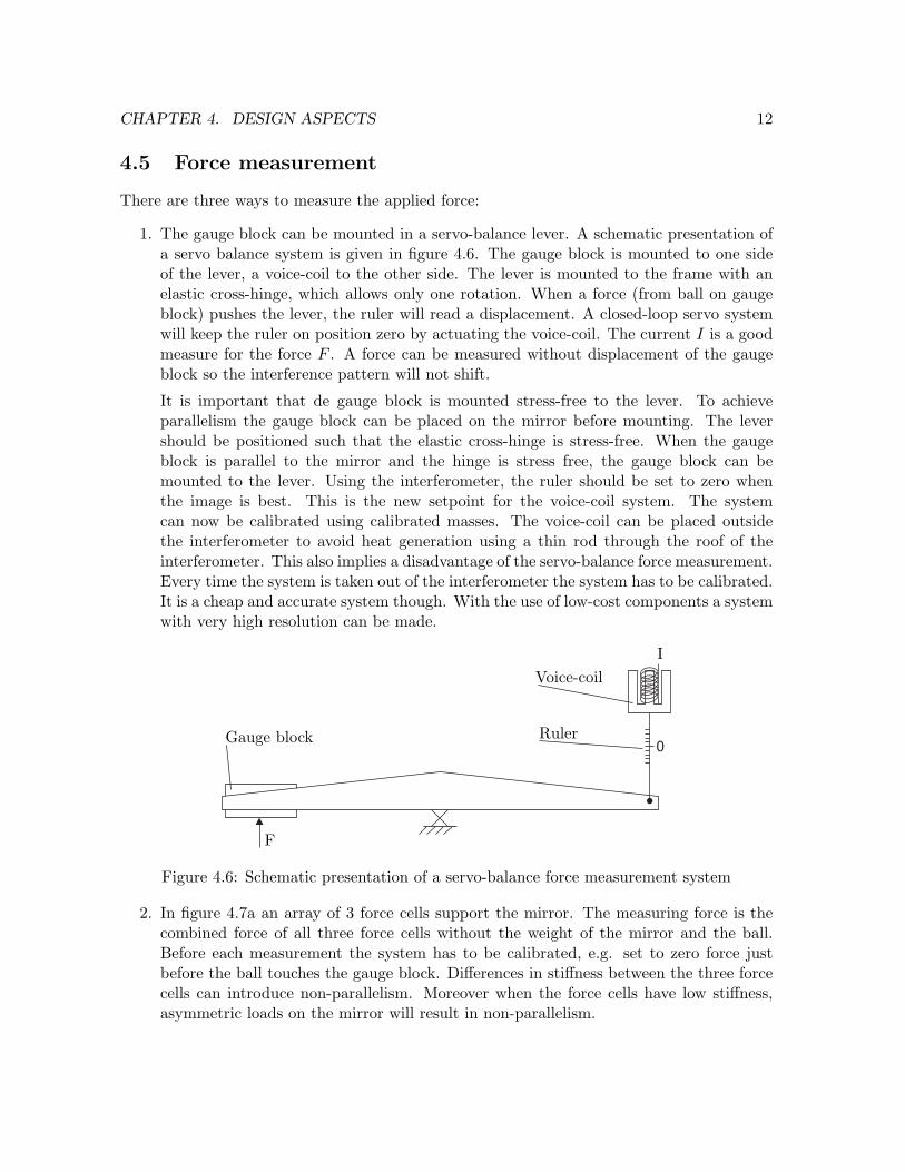
1. The gauge block can be mounted in a servo-balance lever. A schematic presentation ofa servo balance system is given in figure 4.6. The gauge block is mounted to one sideof the lever, a voice-coil to the other side. The lever is mounted to the frame with anelastic cross-hinge, which allows only one rotation. When a force (from ball on gaugeblock) pushes the lever, the ruler will read a displacement. A closed-loop servo systemwill keep the ruler on position zero by actuating the voice-coil. The current I is a goodmeasure for the force F . A force can be measured without displacement of the gaugeblock so the interference pattern will not shift.
It is important that de gauge block is mounted stress-free to the lever. To achieveparallelism the gauge block can be placed on the mirror before mounting. The levershould be positioned such that the elastic cross-hinge is stress-free. When the gaugeblock is parallel to the mirror and the hinge is stress free, the gauge block can bemounted to the lever. Using the interferometer, the ruler should be set to zero whenthe image is best. This is the new setpoint for the voice-coil system. The systemcan now be calibrated using calibrated masses. The voice-coil can be placed outsidethe interferometer to avoid heat generation using a thin rod through the roof of theinterferometer. This also implies a disadvantage of the servo-balance force measurement.Every time the system is taken out of the interferometer the system has to be calibrated.It is a cheap and accurate system though. With the use of low-cost components a systemwith very high resolution can be made.
0
Voice-coil
I
RulerGauge block
F
Figure 4.6: Schematic presentation of a servo-balance force measurement system
2. In figure 4.7a an array of 3 force cells support the mirror. The measuring force is thecombined force of all three force cells without the weight of the mirror and the ball.Before each measurement the system has to be calibrated, e.g. set to zero force justbefore the ball touches the gauge block. Differences in stiffness between the three forcecells can introduce non-parallelism. Moreover when the force cells have low stiffness,asymmetric loads on the mirror will result in non-parallelism.

CHAPTER 4. DESIGN ASPECTS 13
3. It is easy to build in one force cell under the coiled spring (see figure 4.7b). The forcecell does not influence cϕ and cψ. There is no wire attached to the moving part andjust an electrical connection has to be made outside the interferometer. The design canbe compact and costs are reduced to a minimum using only one force cell.
ForceCells
(a) Three force cells
Force cell
(b) One force cell
Figure 4.7: Two different ways to build in force cells
Option 3 is chosen as the best way to measure the measuring force.

CHAPTER 4. DESIGN ASPECTS 14
4.6 Stroke
To measure balls of different diameters a pure translation (with a stroke of 14 mm) of themirror support relative to the gauge block has to be realized. It is assumed that the gaugeblock is rigidly attached to the base frame and that the mirror support is positioned withrespect to the base frame, and thus to the gauge block. To achieve large stroke (14 mm)with good resolution (nm) the actuation consist of two parts; one for the coarse stroke (µmresolution) and one for the fine stroke (subnanometer resolution).
In figure 4.8 the mirror support is mounted on three piezo actuators (e.g. PI P-250, seeappendix B). Actuating them all will result in a fine stroke for force application. Actuatingthem separately can be used for parallel adjustment.
Piezo
Figure 4.8: The piezos added to the design
Now, the mirror support has integrated force application, force measurement and paralleladjustment. The coarse stroke can be realized in different ways:
1. The mirror support can be mounted to the current Z-translation stage. This stageis operated manually to adjust the rough diameter to be measured. This provides arelatively cheap solution to the problems NMi reported. It is important that bendingof the stage is minimized by mounting it stiff to the base frame. Little tilting can occurbut can be compensated by the piezos.
2. For a complete automated solution the mirror support can be placed on three motormike actuators (e.g. the PI M-227, see appendix C). These actuators have a strokeof 25 mm. Actuating them all at the same rate generates a pure translation. Threeactuators, with their control units and amplifiers are required and therefore this isan expensive solution. Before using this option, good requirements have to be knownon what the highly automated ball diameter-measuring machine should be able to do.Smaller diameter ranges seem more applicable in practice.
4.7 Temperature chamber
If vibrations caused by the waterflow are a problem the temperature chamber can be re-placed. A helical steel wire can be the supporting structure for a water tube. To get water of

CHAPTER 4. DESIGN ASPECTS 15
good temperature conditions the same water supply as was used for the current temperaturechamber can be used. The spiral can be dimensioned such that it fits exactly around the new
instrument. The eigenfrequency of the system is given by ωeig =√
km
. High frequency vibra-
tion isolation can be obtained by hanging the spiral on the roof with weak springs, therebycreating a low-pass filter.
4.8 Ball placement
For good measurement it is required that the position of the ball is reproducible. It is desiredthat balls are placed fast and thereby reducing costs. Balls should be handled with care. Itis important that after a series of measurements it is known which ball combines with whichmeasurement report.
In figure 4.9 some concepts for ball handling are proposed. In figure 4.9a the ball iscentered on the mirror by 3 tangential rods with low bending stiffness so the measuring forceis not influenced by friction of the rods. This solution is not automated; the ball is placed byhand. Then the rods are rotated towards the center of the mirror by rotating their connectingpoints. When the ball is centered a measurement series can begin. This feature should beplaced on the manual translation stage.
In figure 4.9b balls are placed in a transport cassette. For each rough ball diameterdifferent cassettes have to be produced. The ball is pushed in a V-groove (stiff in x and y),which gives the position of the ball, using a weak spring. The V-groove is connected througha leaf spring with low stiffness in z direction so the measuring force is influenced minimally.The cassette, on its turn, is pushed to a linear guiding. The inner width should be at least24 mm, the diameter of the laser bundle. The cassettes can contain a number (or barcode),so balls can be recognized easily. A feeding unit has to be designed. This concept can beapplied in a highly automated ball measuring instrument.
Mirror
(a) Tangential rods
65465765
A A’
Leaf spring
Mirror
Cassette
Side viewSection A - A’
(b) Transport cassette
Figure 4.9: Two different ways for ball placement (top view)

Chapter 5
Concept
Combining the best solutions for the different design aspects results in a concept for a newball diameter-measuring instrument. The mirror support with the chosen force applicationand force measurement system is mounted to the original manual translation stage (see figure5.1). It is important that the mirror support is mounted to the stage such that the mirror isas close to the stage as possible. This is achieved by rotating the mirror support around θ
and placing one piezo on the outside. For measuring a serie of balls with the same diameterthe translation stage has to be set manually. The ball is centered by the system of figure 4.9a.As mentioned in section 4.1 the base frame can only be designed when all components arechosen. Because this is a concept study the frame is not designed. One has to take in mindthat the translation stage has to be mounted very stiff to the frame, as well as the gaugeblock (see section 4.3).
The concept provides a relative cheap solution to the problem sketched by NMi. Oneforce cell, 3 piezo actuator tips and one EDM-produced guiding form most of the costs.
Figure 5.1: The proposed concept
16

Chapter 6
Conclusions and Recommendations
After defining design requirements, the ball diameter-measuring instrument is divided intomain design aspects. Solutions have been found for each design aspect. Combining thebest solutions for the different design aspects resulted in a concept for a new ball diameter-measuring instrument. Once the rough diameter is set, a ball can be measured at differentforces without entering the interferometer. Thereby temperature conditions will stay thesame. More forces in a wider range than before can be applied and measured. The force-Hertz-indentation plots will be more accurate and better fits can be made. The presentedconcept is a schematic lay-out. Special attention has to be paid to dimensions, componentchoice, material choice, etc. when the instrument is built.
Concepts to automate the ball placement have been mentioned so series of balls can bemeasured without entering the interferometer. It is expensive to design a fully automatedinstrument that measures a serie of balls with different diameters, because expensive actuatorsand their control instruments are required.
Recommendations
• The presented concept is a schematic lay-out, special attention has to be paid to di-mensions, component choice, material choice, etc when the instrument is built.
• When a completely automated ball diameter-measuring machine is desired, it seemlogical that smaller diameter ranges are chosen.
• A new temperature chamber can be built with little costs.
17

Bibliography
[1] Roger T. Fenner. Mechanics of Solids. CRC Press, 1999.
[2] Gerard J. Kotte and Han Haitjema. A ball diameter-measuring instrument in a gauge blockinterferometer. NMi Van Swinden Laboratorium, Technische Universiteit Eindhoven.
[3] P.C.J.N Rosielle and E.A.G. Reker. Constructieprincipes 1, bedoeld voor het nauwkeurig
bewegen en positioneren. Number 4007. Technische Universiteit Eindhoven, 2002.
18
Appendix A
Finite element results
Supporting points
Bottom view
Figure A.1: Z-displacement of mirror with a force of 4 N; point symmetric support
Supporting points
Bottom view
Figure A.2: Z-displacement of mirror with a force of 4 N; center of mirror supported
19
Appendix B
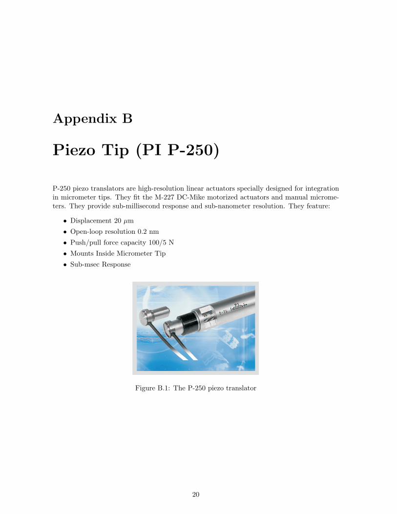
Piezo Tip (PI P-250)
P-250 piezo translators are high-resolution linear actuators specially designed for integrationin micrometer tips. They fit the M-227 DC-Mike motorized actuators and manual microme-ters. They provide sub-millisecond response and sub-nanometer resolution. They feature:
• Displacement 20 µm
• Open-loop resolution 0.2 nm
• Push/pull force capacity 100/5 N
• Mounts Inside Micrometer Tip
• Sub-msec Response
Figure B.1: The P-250 piezo translator
20
Appendix C
Motor Mike (PI M-227)
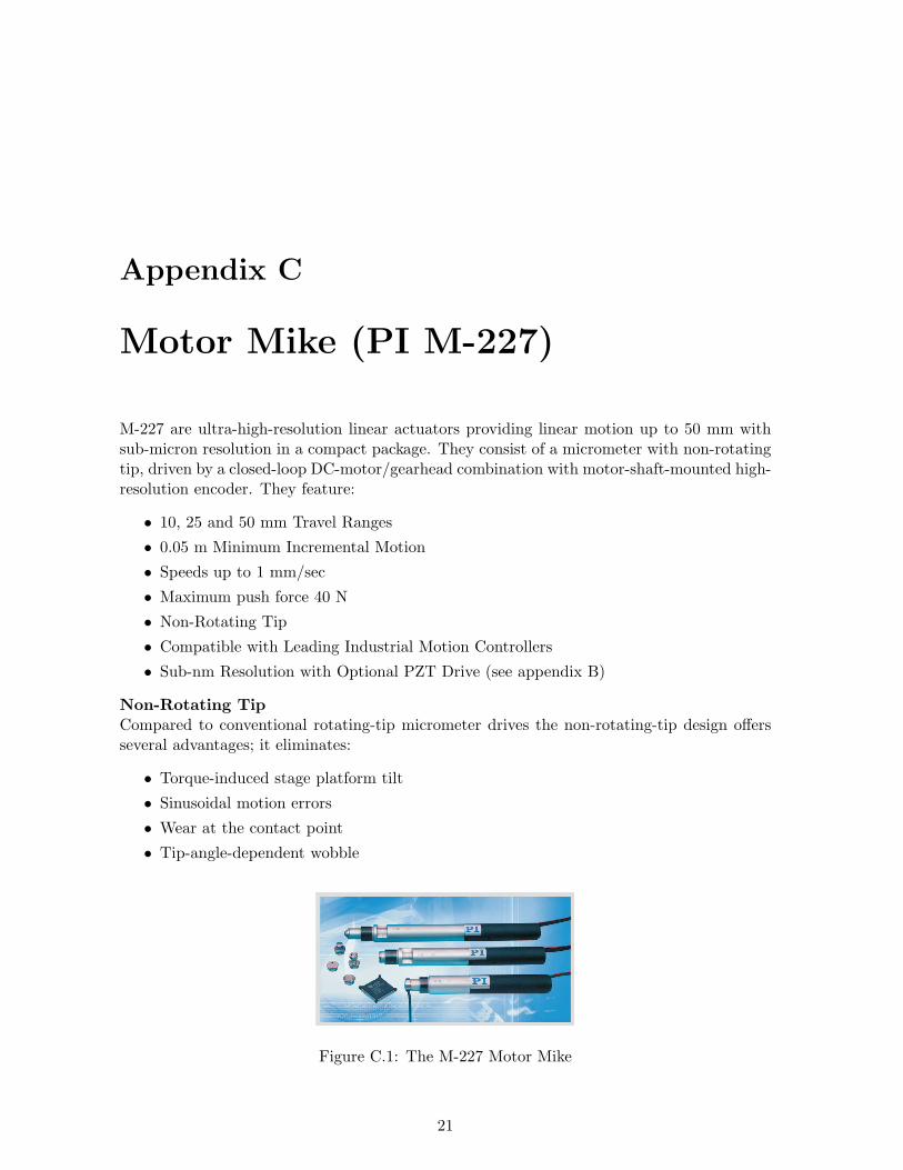
M-227 are ultra-high-resolution linear actuators providing linear motion up to 50 mm withsub-micron resolution in a compact package. They consist of a micrometer with non-rotatingtip, driven by a closed-loop DC-motor/gearhead combination with motor-shaft-mounted high-resolution encoder. They feature:
• 10, 25 and 50 mm Travel Ranges
• 0.05 m Minimum Incremental Motion
• Speeds up to 1 mm/sec
• Maximum push force 40 N
• Non-Rotating Tip
• Compatible with Leading Industrial Motion Controllers
• Sub-nm Resolution with Optional PZT Drive (see appendix B)
Non-Rotating TipCompared to conventional rotating-tip micrometer drives the non-rotating-tip design offersseveral advantages; it eliminates:
• Torque-induced stage platform tilt
• Sinusoidal motion errors
• Wear at the contact point
• Tip-angle-dependent wobble
Figure C.1: The M-227 Motor Mike
21