Models, methods and tools for car body development
22
Nicklas Bylund Models, methods and tools for car body development 2002:15 LICENTIATE THESIS Licentiate thesis Institutionen för Tillämpad fysik, maskin- och materialteknik Avdelningen för Datorstödd maskinkonstruktion 2002:15 • ISSN: 1402-1757 • ISRN: LTU-LIC--02/15--SE
Transcript of Models, methods and tools for car body development

Nicklas Bylund
Models, methods and toolsfor car body development
2002:15
LICENTIATE THESIS
Licentiate thesis
Institutionen för Tillämpad fysik, maskin- och materialteknikAvdelningen för Datorstödd maskinkonstruktion
2002:15 • ISSN: 1402-1757 • ISRN: LTU-LIC--02/15--SE

Models, methods and tools for carbody development
This is an introductory part,articles are not included.
Paperback including completearticles can be ordered by sending an email to:
Nicklas Bylund
May 2002
Division of Computer Aided DesignLuleå University of Technology
SE-971 87 Luleå, Sweden
ii
PrefaceThe research presented in this licentiate thesis has been carried out at the advanced bodyengineering group at Volvo Car Corporation (VCC). The research has been done whileenrolled at the Division of Computer Aided Design (CAD) at Luleå University ofTechnology. The research was initiated by VCC as part of the VCC industrial PhD programand in close co-operation with the CAD division at Luleå University of Technology. I wish toexpress my gratitude to my industrial supervisor Jonas Forssell, MSc and my academicsupervisor Professor Lennart Karlsson for giving me support, inspiration and stimulatingdiscussions throughout my research work. I would also like to thank the advanced bodyengineering group at VCC, my colleagues at the CAD-division and my co-authors.The gratefully acknowledged financial support has been provided by the Swedish Foundationfor Strategic research and Volvo Car Corporation. The research has been conducted within theENDREA national graduate program. ENDREA has contributed with a valuable researchnetwork as well as interesting courses.
Gothenburg, May 2002
Nicklas Bylund

iii
AbstractThis licentiate thesis deals with the development of complex mechanical structures, fromconcept to detail design, as applied to car bodies. The role of concepts has been examined anda standardised language based on three organ types (beams, joints and panels) has been madeto break down and quantify concept performance. Concept selection has been addressed withcare, not to impose an off-the-shelf method, but to identify the needs of the particularsituation.
Efforts have been made to clarify how computer tools and analysis methods are used inproduct development in industry today. It has been found that the design and the analysisactivities are separated. In order to speed up the development, a concurrent engineeringapproach is needed. This calls for integration of computer support and analysis in thedevelopment process. Based on the above findings, a new development process for car bodieshas been developed, reaching from concept to detail design. An analysis tool has beendeveloped, tailor-made according to the broken down concept performance, and necessary inthe presented process. The main feature of the tool is the possibility to transfer part of theanalysis from simulation experts to design engineers, thereby increasing the simulation usagein product development. The first tests of ADRIAN in an industrial environment showed thattechnical issues such as analysis stability and speed are satisfied, and that the target group, thedesign engineers without experience of analysis, found it easy and valuable to use, which isequally important. The overall purpose is to arrive at a simulation-driven design based onrequirements broken down to local level rather than a simulation-verified design.
Keywords:concept development, concept selection, detail design, supportive software, car body,engineering design

iv
ThesisThis thesis comprises an introductory part and the following papers:
Paper ABYLUND, N., FREDRICSON, H. AND THOMPSON, G.A design process for complex mechanical structures using Property BasedModels, with application to car bodies. In the proceedings to Design 2002 Conference, 14-17 of May 2002, Dubrovnik, Croatia.
Paper BBYLUND, N. AND ERIKSSON, M.Simulation Driven Car Body Development Using Property Based Models SAE paper 2001-01-3046, in proceedings to IBEC 2001. (Conference postponed to 8-12 July 2002.)
Paper C
GRANTE, C. AND BYLUND, N.A Study of the Effects of Different System Architectures on the Development Process.In the proceedings to Design 2002 Conference, 14-17 of May 2002, Dubrovnik, Croatia.
Paper DBYLUND, N., SANDSTRÖM, H. AND SHAMLO, M.ADRIAN a program for evaluating the stiffness of joints and its application in the development process.To be submitted.
v
Contents
1 INTRODUCTION........................................................................................................................................................ 1
1.1 BACKGROUND .............................................................................................................................................................11.2 MOTIVATION...............................................................................................................................................................11.3 VISION ..........................................................................................................................................................................1
2 CORPORATE CONTEXT........................................................................................................................................ 1
3 KNOWLEDGE DOMAINS....................................................................................................................................... 2
3.1 PRODUCT DEVELOPMENT ..........................................................................................................................................23.2 DESIGN RESEARCH......................................................................................................................................................23.3 CONCURRENT ENGINEERING.....................................................................................................................................33.4 CONCEPT DEVELOPMENT ...........................................................................................................................................33.5 CONCEPT SELECTION..................................................................................................................................................33.6 PRODUCT MODELS......................................................................................................................................................43.7 PRODUCT ARCHITECTURE ..........................................................................................................................................43.8 DETAIL DESIGN............................................................................................................................................................4
4 PROBLEM FORMULATION.................................................................................................................................. 4
4.1 RESEARCH QUESTION.................................................................................................................................................44.2 RESEARCH APPROACH................................................................................................................................................44.3 INDUSTRIAL IMPORTANCE .........................................................................................................................................54.4 ACADEMIC IMPORTANCE ...........................................................................................................................................5
5 DESIGN OF COMPLEX MECHANICAL STRUCTURES ............................................................................ 5
5.1 DESCRIPTION ...............................................................................................................................................................65.2 PRESCRIPTION .............................................................................................................................................................65.3 THE USE OF A PROPERTY BASED MODEL, (PBM)..................................................................................................75.4 STATUS OF ANALYSIS SOFTWARE SUPPORTING THE PROPOSED DEVELOPMENT PROCESS DURING CONCEPTDEVELOPMENT .......................................................................................................................................................................85.5 STATUS OF ANALYSIS SOFTWARE SUPPORTING THE DESIGN ENGINEER DURING DETAIL DESIGN ...................95.6 INTRODUCTION IN INDUSTRY..................................................................................................................................10
6 DISCUSSION OF APPENDED PAPERS ...........................................................................................................10
6.1 PAPER A.....................................................................................................................................................................108.2 PAPER B..........................................................................................................................................................................116.2 PAPER C......................................................................................................................................................................116.3 PAPER D.....................................................................................................................................................................13
7 CONCLUSIONS .........................................................................................................................................................13
8 FUTURE WORK........................................................................................................................................................14
8.1 JOINT MEASUREMENTS.............................................................................................................................................148.2 IMPROVED CONCEPT SELECTION ............................................................................................................................14
9 REFERENCES............................................................................................................................................................14
Appended papers
Paper ABYLUND, N., FREDRICSON, H. AND THOMPSON, G.A design process for complex mechanical structures using Property Based

vi
Models, with application to car bodies. In the proceedings to Design 2002 Conference, 14-17 of May 2002, Dubrovnik, Croatia.
Paper BBYLUND, N. AND ERIKSSON, M.Simulation Driven Car Body Development Using Property Based Models SAE paper 2001-01-3046, in proceedings to IBEC 2001. (Conference postponed to 8-12 July 2002.)
Paper C
GRANTE, C. AND BYLUND, N.A Study of the Effects of Different System Architectures on the Development Process.In the proceedings to Design 2002 Conference, 14-17 of May 2002, Dubrovnik, Croatia.
Paper DBYLUND, N., SANDSTRÖM, H. AND SHAMLO, M.ADRIAN a program for evaluating the stiffness of joints and its applicationin the development process. To be submitted.

Models, methods and tools for car body development. N. Bylund
1
1 Introduction
1.1 Background
To stay competitive and lead the market, a company needs to be responsive to changing customerdemands and moves from their competitors, [Wheelwright and Clark 92]. This implies that productdevelopment has to be fast in order to incorporate the latest trends in the product. Therefore, in anaugmenting competition, shorter development cycles leading to shorter time-to-market can be thekey to gain market shares, product profit and customer satisfaction, [Wheelwright and Clark 92]. Inthe meantime, industry also has to work with limited budgets although product complexity andcustomer demands are growing. In order to obtain a successful development of products, industrymust understand both the strong and the weak points in their own development processes and toolsduring product development [Pugh 90]. When a company has achieved these insights about theirproduct development it is possible to formulate and propose an alternative development processleading to more successful product development.
1.2 Motivation
Designing a complex mechanical structure involves a chain of activities that have tobe mastered, such as requirement breakdown, concept development, concept selection and detaildesign. Development lead-time and product performance are strongly affected by success in each ofthese phases. A multitude of tools for designing geometry in both 2D and 3D has existed for severalyears and a wide range of analysis tools for simulating mechanical performance also exists. Evenwith these tools, the design and verification of a structure such as a car body takes a long time,while demands for shorter lead-time and higher performance keeps rising. A more concurrentdesign process is therefore called for, with better coupling between design and simulation.
1.3 Vision
The vision is to create a robust development process for complex mechanical structures and apply itto car body development. Development is done faster and at the same time enhancing the possibilityto introduce new technology. The process contains guidelines, experimental methods andsupportive software. The development process is dealt with from requirements to detail design.Concept selection is addressed with the aim to get acceptance throughout the organisation. Thefocus lies on supporting the drafter/design engineer with low level requirements and easy-to-usetools to check if the requirements are fulfilled. Changes in the requirements are handled rapidly andeconomically. Knowledge from competitor analysis and earlier in-house projects is automaticallyavailable as a reference during the concept phase and further on during the detail design phase.
2 Corporate contextThe work resulting in this thesis has been done in close collaboration with industry. The main partof the research has been done at Volvo Car Corporation in Gothenburg, Sweden. Contact has alsobeen made with other companies in the Ford Motor Company, especially with Ford in Detroit, USAand Ford in Cologne, Germany.
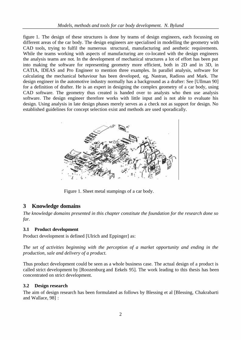
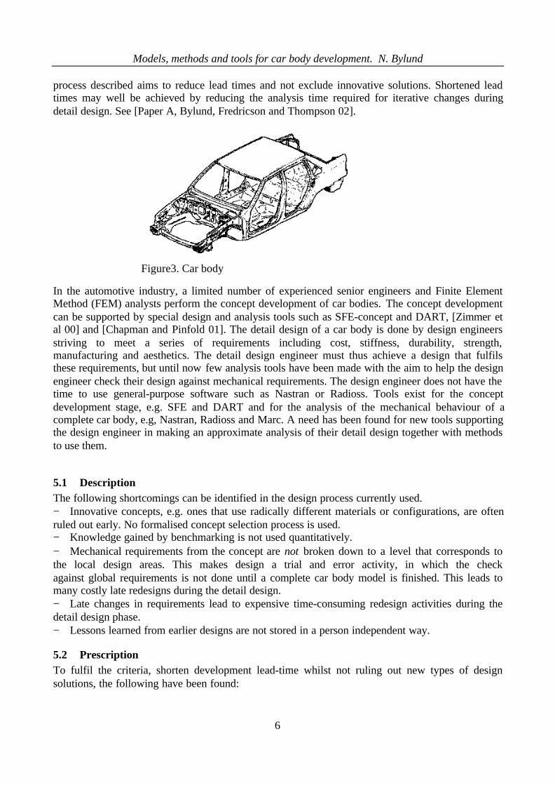
Some common tendencies are seen through the automotive industry. Car bodies consist of sheetmetal stampings of fairly complex geometry that for the most part are spot-welded together, see
Models, methods and tools for car body development. N. Bylund
2
figure 1. The design of these structures is done by teams of design engineers, each focussing ondifferent areas of the car body. The design engineers are specialised in modelling the geometry withCAD tools, trying to fulfil the numerous structural, manufacturing and aesthetic requirements.While the teams working with aspects of manufacturing are co-located with the design engineersthe analysis teams are not. In the development of mechanical structures a lot of effort has been putinto making the software for representing geometry more efficient, both in 2D and in 3D, inCATIA, IDEAS and Pro Engineer to mention three examples. In parallel analysis, software forcalculating the mechanical behaviour has been developed, eg, Nastran, Radioss and Mark. Thedesign engineer in the automotive industry normally has a background as a drafter: See [Ullman 90]for a definition of drafter. He is an expert in designing the complex geometry of a car body, usingCAD software. The geometry thus created is handed over to analysts who then use analysissoftware. The design engineer therefore works with little input and is not able to evaluate hisdesign. Using analysis in late design phases merely serves as a check not as support for design. Noestablished guidelines for concept selection exist and methods are used sporadically.
3 Knowledge domainsThe knowledge domains presented in this chapter constitute the foundation for the research done sofar.
3.1 Product developmentProduct development is defined [Ulrich and Eppinger] as:
The set of activities beginning with the perception of a market opportunity and ending in theproduction, sale and delivery of a product.
Thus product development could be seen as a whole business case. The actual design of a product iscalled strict development by [Roozenburg and Eekels 95]. The work leading to this thesis has beenconcentrated on strict development.
3.2 Design researchThe aim of design research has been formulated as follows by Blessing et al [Blessing, Chakrabartiand Wallace, 98] :
Figure 1. Sheet metal stampings of a car body.
Models, methods and tools for car body development. N. Bylund
3
The aim of engineering design research is to support industry by developing knowledge, methodsand tools which can improve the chances of producing a successful product.
Focusing the research only to products is not enough to fulfil the aim above, because design is notonly a technical process but also a social process with relations between individuals andorganisations, [Minneman 91]. Design research is therefore multi-disciplinary. Design involvesnumerous factors including people, products, tools and organisations. Each of these factors has itsresearch tradition and methodology: in social, engineering, computer and management sciences.The second and third factors mentioned are issues normally treated in engineering while the firstand last are not, making design research reaching beyond the traditional engineering scope. Thisthesis dissertation concentrates on traditional engineering domains, but during the development ofsoftware tools issues such as man–machine interactions have been addressed.
3.3 Concurrent engineeringFor product development to be successful, the production process has to be anticipated alreadyduring the design phase. Ullman [Ulman 97] describes this as concurrent design, where the functionof a product relates to the following three elements: shape, material and production. Each of theseelements has its stakeholders. Shape is represented by the engineering designer struggling to get thelatest look and the structural engineer struggling to get the most mechanically efficient design. Thestructural engineer also strives to get strong high-end materials while the production engineer focuson the possibility to manufacture the product in the least expensive way. In this thesis the wordconcurrent is also used to describe a simultaneous design and analysis activity.
3.4 Concept developmentWhen a new product is to be designed several different solutions are often possible, which can beembodied in concepts. A concept is an early representation of a product, incorporating only aminimum of details; just enough to show the main characteristics of the product, or, according toThompson, [Thompson 99]:
A concept defines and describes the principles and engineering features of a system, machine orcomponent which is feasible and which has the potential to fulfil all the essential designrequirements.
A concept is thus faster and cheaper to develop and change than the final product design.
3.5 Concept selectionWhen a multitude of concepts are developed, the concept that best achieves the requirements has tobe chosen. This process is called concept selection. Many different selection methods exist andmany of them are matrix based, such as the paired comparison matrix, [Isaksen, Dorval andTreffinger 94] and [Pugh 90]. Some weigh the requirements according to their relative importance,as in the concept scoring method by [Ulrich and Eppinger 95]. Roozenburg and Eekels havecompiled and explained a great range of selection methods in [Roozenburg and Eekels 95]. Theimportance of concept selection resides in the fact that for a large project returning to the conceptstage after the detail design stage has been launched is often unfeasible and the characteristics andperformances of a product are already determined by the concept, [Thompson 99].

Models, methods and tools for car body development. N. Bylund
4
3.6 Product modelsOn a high/global level a product can be represented as a prototype defined as an approximation ofthe product along one or more dimensions of interest [Ulrich and Eppinger 95]. Each dimensionputs forwards one characteristic of the product. Prototypes can be both physical and virtual. Avirtual prototype can be a 3D drawing where surfaces and light sources are natural-like andfurthermore it could be moveable in space. Prototypes can also be of analytical character and in thecase of a mechanical product, permitting simulation of their mechanical behaviour. A concept is anearly form of product model where the main characteristics are represented.
Early in the development process, concepts have to be modelled in an efficient way independent ofdetail solution, so as not to bias the detail solution. [Thompson 99] To handle this, Hubka et al,[Hubka, Andreasen and Eder 88] use organs. These represent functional implementation inproducts, although they are not detail designed. Organs are often called function carriers, expressinghow the system realises its functions. In other words, if a product needs a defined stiffness in somedirection, a spring organ can be used in the concept. The organ representation leaves the decision todetail design whether a leaf spring or a cylindrical spring or some other spring type is to be used. Inthis thesis organs are used to build up product models for concepts.
3.7 Product architectureThe type of interaction between organs [Hubka, Andreasen and Eder 88] or chunks [Ullrich andEppinger 95] results in different product architectures. The main two product architectures are theintegrated and the distributed. [Ullrich and Eppinger 95] The product architecture affects thedevelopment process and the possibility to upgrade a product. An integrated architecture needsmore iterations during its development than a distributed architecture and is more difficult toupgrade. The structures focused in this thesis is of integrated nature.
3.8 Detail design
A good concept is a necessary but not sufficient condition to ensure a successful product. While theconcept limits the maximum achievable performance of a product, the detail design decides theactual performance. For example, if an aeroplane is to be designed and the concept is a traditionalpropeller driven aeroplane it will not be able to travel in the vicinity of or faster than the speed ofsound due to the aerodynamic properties of a propeller. The actual aeroplane designed from theconcept will thus travel at some velocity lower than sound, no matter how the propeller is designedin detail. As described earlier, current software for this phase are mostly focused on geometricdescriptions, e.g. CATIA and I-DEAS.
4 Problem formulation
4.1 Research question
How to develop, compare and evaluate new mechanical structure technologies for car bodies?
4.2 Research approach
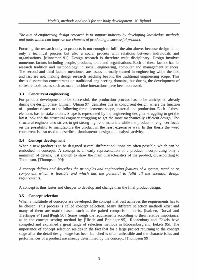
To handle the multidisciplinary nature of design research, Blessing et al propose a researchmethodology for design research, [Blessing, Chakrabrit and Wallace 98]. The methodology containsthe four steps: Criteria, Description I, Prescription and Description II. See Figure 2.The Criteria are a measure of success; the problem is analysed in Description I; a solution isproposed in Prescription; and the proposed solution is evaluated with respect to the initial criteria in
Models, methods and tools for car body development. N. Bylund
5
Description II. The methodology stresses, especially, the importance of both descriptive andprescriptive steps, as well as measurable criteria. The studies presented in this thesis have beenperformed in industry as exploratory research. As Blessing et al state, due to the time available, it ishard to go through the whole loop all the way to description II in one project, this licentiate thesisreaches the Prescription stage
4.3 Industrial importanceThe possibilities and advantages of computer aided simulation of mechanical structures togetherwith structured concept development and concept selection are not fully exploited in industry today.Achieving a more efficient concept treatment and simulation process will enhance a more fairevaluation of innovative concepts leading to better exploration of the solution space. Morealternative solutions augment the chances of designing a competitive product. Providing designengineers with appropriate tools and methods reduces lead-time by permitting a more simulation-driven development process.
4.4 Academic importanceThe descriptive and the prescriptive parts of this thesis develop knowledge about how concepts andconcept selection can be made to give optimal support to the detail design. In addition, anidentification is made of when the impact is greatest in using an analysis tool in the developmentprocess of structures. Finally, experience is gained of the possibilities and difficulties whenintroducing a new development process and corresponding tools in a company's productdevelopment.
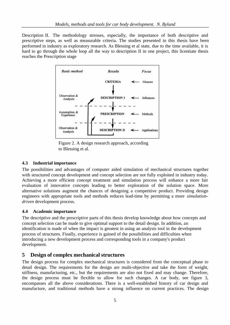
5 Design of complex mechanical structuresThe design process for complex mechanical structures is considered from the conceptual phase todetail design. The requirements for the design are multi-objective and take the form of weight,stiffness, manufacturing, etc., but the requirements are also not fixed and may change. Therefore,the design process must be flexible to allow for such changes. A car body, see figure 3,encompasses all the above considerations. There is a well-established history of car design andmanufacture, and traditional methods have a strong influence on current practices. The design
Figure 2. A design research approach, accordingto Blessing et al.
Models, methods and tools for car body development. N. Bylund
6
process described aims to reduce lead times and not exclude innovative solutions. Shortened leadtimes may well be achieved by reducing the analysis time required for iterative changes duringdetail design. See [Paper A, Bylund, Fredricson and Thompson 02].
In the automotive industry, a limited number of experienced senior engineers and Finite ElementMethod (FEM) analysts perform the concept development of car bodies. The concept developmentcan be supported by special design and analysis tools such as SFE-concept and DART, [Zimmer etal 00] and [Chapman and Pinfold 01]. The detail design of a car body is done by design engineersstriving to meet a series of requirements including cost, stiffness, durability, strength,manufacturing and aesthetics. The detail design engineer must thus achieve a design that fulfilsthese requirements, but until now few analysis tools have been made with the aim to help the designengineer check their design against mechanical requirements. The design engineer does not have thetime to use general-purpose software such as Nastran or Radioss. Tools exist for the conceptdevelopment stage, e.g. SFE and DART and for the analysis of the mechanical behaviour of acomplete car body, e.g, Nastran, Radioss and Marc. A need has been found for new tools supportingthe design engineer in making an approximate analysis of their detail design together with methodsto use them.
5.1 DescriptionThe following shortcomings can be identified in the design process currently used.− Innovative concepts, e.g. ones that use radically different materials or configurations, are oftenruled out early. No formalised concept selection process is used.− Knowledge gained by benchmarking is not used quantitatively.− Mechanical requirements from the concept are not broken down to a level that corresponds tothe local design areas. This makes design a trial and error activity, in which the checkagainst global requirements is not done until a complete car body model is finished. This leads tomany costly late redesigns during the detail design.− Late changes in requirements lead to expensive time-consuming redesign activities during thedetail design phase.− Lessons learned from earlier designs are not stored in a person independent way.
5.2 PrescriptionTo fulfil the criteria, shorten development lead-time whilst not ruling out new types of designsolutions, the following have been found:
Figure3. Car body

Models, methods and tools for car body development. N. Bylund
7
− Each concept should be represented in the same language by a property based model (PBM) andbe of the same level of maturity to permit fair concept selection.− Using the same metrics when analysing competitors makes benchmarking more efficient, e.g.competitors' performance can be quantified.− Concept selection must gain acceptance throughout the organisation. Therefore, methods thatblindly total up positive and negative features to get an overall score are dangerous.− The concept model should permit breakdown of requirements into a local level to give designengineers local requirements for their design area.− Design engineers should be given easy-to-use analysis tools to check if their design fulfils thelocal requirements. This reduces the need of costly analysis loops at complete car body level, andenhances small parallel/concurrent iterations.− When design engineers use analysis tools themselves, more design alternatives can be tested ina shorter time and the features from the concept model are not lost on the way to detail design.− To use the capabilities of a concept thoroughly, it should live in parallel with detail designbecause the feasibility and cost of late unpredicted changes in global requirements can be evaluatedmore easily on the concept model than the detailed model. To make a parametric concept model istherefore valuable. It can be scaled to confront a broad range of changes in requirements, and is thusan adaptive concept model.− A library of earlier designs should be made, thus enhancing a learning organisation.
5.3 The use of a Property Based Model, (PBM).Figure 4 shows the design process that is the subject of the present research. It can be seen that thestarting point for all projects is a set of requirements (mass, structural integrity, etc.) [Fenton 96]. AProperty Based Model (PBM), [Paper B, Bylund and Eriksson 01], is built up for each concept, andrepresents the mechanical and spatial properties of the body concept. The PBM is constructed fromorgans, [Hubka, Andreasen and Eder 88], which represent requirements at a local level. The chosenorgans for the car body are beams, joints and panels, [Paper B, Bylund and Eriksson]. In the buildup and break down activity, the PBM models for new designs and existing competitors' designs aregenerated by in-house design teams. A library of organs is used to generate PBM modelsefficiently. Typical elements are beam cross-sections and joint properties. Each project generatesnew organs creating an extensive knowledge bank. Such a bank is a resource of expertise, andknowledge is thus readily transferred and the design process is not dependent on particularindividuals and their subjective value judgements [Paper A, Bylund, Fredricson and Thompson 02].
An optimisation procedure is used to normalise the alternative concept PBM models with respect tokey global requirements, e.g. global stiffness, weight, crash worthiness, etc. The normalisationassures that all concepts are on the same level of maturity. For example, a new innovative conceptshould not just show a fraction of its performance while an old well-known technology results in aconcept close to its maximum performance. The results of the procedure are used as the basis forevaluation of the concepts. The PBM that best fits the quantitative and qualitative criteria isselected. This is a decisive aspect of the design process and is not left to the numerical outcome ofany particular design evaluation method. The selection involves the decision-making processeswithin the company as a whole, and it is important that all relevant parties contribute to, and accept,the outcome of evaluation.

Models, methods and tools for car body development. N. Bylund
8
The selected PBM contains all the properties of the model at the organ level. These properties arethe guidelines for the detail design engineers. During the detail design phase, the designer is thusprovided with requirements at organ level. The detail design engineer is supported by easy-to-usecomputational tools, [Paper D, Bylund, Sandström and Shamlo 02] to check if his design fulfils thelocal criteria. In addition, he/she can use particular solutions from earlier designs stored in a library.Local changes required at the later stages of design can be considered objectively by the detaildesigner. The changes can be tested against the solution requirements (stiffness of the organs, etc.)and if the requirements remain satisfied, then the change can be met.
5.4 Status of analysis software supporting the proposed development process duringconcept development
In order to build a PBM concept model and break down the global requirements on the structure, toa local level, any general-purpose FEM tool could be used. But to fully exploit the possibilities ofPBM formulation at the concept stage, the preference is for tools permitting fast-parameterisedgeometry development with the possibility of automatic re-meshing, such as in SFE-Concept[Zimmer et al 00] or DART [Chapman and Pinfold 01], and the possibility of optimising theperformance of the organs with respect to global criteria, as in STRUCTOPT, [Harald et al 02].Optimising all concept PBMs puts them on the same level of maturity, enhancing a fair conceptselection, see section 5.3. STRUCTOPT works with gradient based methods and makes topological
Requirements
Competitor
Concept idea
Evaluation
Bui
ld u
p &
Bre
ak d
own
Too
ls /
Met
hods
/ B
ank
PBM
Selectedsolution
Detaileddesign
CO
NC
EPT
PRO
JEC
T
Figure 1. PBM based process for design of complex mechanical structuresFigure 4. PBM based process for design of complex mechanical structures.
Opt
imis
atio
n

Models, methods and tools for car body development. N. Bylund
9
optimisation, e.g. deletes organs that do not contribute to the overall performance. The software isstill in the development stage and so far handles beams and joints in the linear domain. Targetcascading is an optimisation method in which requirements or targets at different levels of detail arerelated. Furthermore, mixing of different types of requirements is permitted [Michelena et al 01].The optimisation routines in target cascading can be both gradient based and non-gradient basedpermitting both continuous and discrete variables.
5.5 Status of analysis software supporting the design engineer during detail design
As stated in the presented process, the design engineers should be able to analyse the performanceof their detail design and compare it with the local requirements from the PBM. Furthermore,relative analysis is valuable, where the results of a change in design can be quantified, e.g. a changeof gauge or access holes. Tools for enhancing these analyses have to be integrated with the CAD-tool used in the detail design and developed with the needs of the design engineer in focus, [PaperD, Bylund Sandström and Shamlo 02 ] and [Lundgren and Johansson 01], see figure 5. As a part ofthis thesis a tool for analysing the stiffness of automotive joints, called ADRIAN, has beendeveloped [Paper D, Bylund Sandström and Shamlo 02] and is being introduced at Volvo CarCorporation.
Organ
load case Beam
Linear static
Figure 5. Status of analysis software supporting the designengineer.
Joint Panel
DAMIDA,[Lundgren andJohansson 01]
Nonlinear DAMIDA,[Lundgren andJohansson 01]
Future Work
ADRIAN [PaperD, Bylund,Sandström andShamlo]
Future work
Future work

Models, methods and tools for car body development. N. Bylund
10
5.6 Introduction in industryWhen introducing new methods and tools into the industry, ownership, usage and maintenance arethe corner stones. The ownership of a software has to be clear; if the software is also used by otherparties than the owners a clear strategy for cost sharing has to be developed. Maintenance of a toolis needed to cater for changes in versions of software. Allocating time and money for maintenanceright at the start assures a problem-free usage in the future. The introduction of new methods mayinvoke other ways of work division than have traditionally been used.
6 Discussion of appended papersFour papers, A-D, have been included in this licentiate thesis. The first paper, A design process forcomplex mechanical structures using Property Based Models, with application to car bodies, is thebackbone of this thesis and describes the design process made for reaching the vision, presented insection 5, see also 1.3. The second paper, Simulation Driven Car Body Development UsingProperty Based Models, describes the concept of Property Based Models (PBM) more in depth,with some examples. The third paper, A Study of the effects of different system architectures on thedevelopment process, is of a theoretical nature and address the role of different productarchitectures in design. Finally the fourth paper, ADRIAN a program for evaluating the stiffness ofjoints and its application in the development process, describes ADRIAN, one of the programs , forenhancing the design process proposed in the first two papers.
6.1 Paper A
BYLUND, N., FREDRICSON, H. AND THOMPSON, G.A design process for complex mechanical structures using Property BasedModels, with application to car bodies. In the proceedings to Design 2002 Conference, 14-17 May2002, Dubrovnik, Croatia.
The paper proposes a method on how to handle development of complex mechanical structures,intended to fulfil the vision presented in section 1.3.
The design of complex mechanical structures is multi-objective and includes the treatments of awide range of requirements such as quantitative, qualitative, subjective and objective. An exampleof this type of structure is a car body, where design has a long tradition from which valuableexperience can be drawn. However, fixation to old practices has to be avoided. The design processdescribed in the paper aims to reduce lead-time while not excluding innovative solutions. Byrepresenting all concepts on a common base as a property based model and use optimisation, an
Paper Method Application Theory
A x x
B x x
C x
D x
Figure 6. The focus of the papers.

Models, methods and tools for car body development. N. Bylund
11
objective analysis can be done early, thereby only viable concepts will emerge for further selection.The data gained in early phases is used as input to detail design, reducing iterations.
The idea of breaking down both concepts and competitors to organ level makes comparison easywhile quantities are of the same type. Using the same tools for breakdown as in build-up(embodiment design) and detail design creates an efficient and self-learning organisation. Conceptsnot meeting quantitative mechanical requirements after optimisation are rejected; thus only viableconcepts need to be considered during concept selection. Qualitative criteria can thus be considereddeeper in the selection.
Concept selection processes using paired comparison analysis are not without problems. In order toend up with a concept that is accepted throughout the organisation, it is important not to let somebad aspects be compensated by some other very good aspects. Another way to take decisions iscalled for.
8.2 Paper B
BYLUND, N. AND ERIKSSON, M.Simulation Driven Car Body Development Using Property Based Models SAE paper 2001-01-3046,in proceedings to IBEC 2001. (Conference postponed to 8-12 July 2002.)
In order to efficiently develop and evaluate a concept, and finally incorporate the concept featuresinto final products, concepts have to be represented in a common language. The conceptual designis broken down to a numerical PBM representing the mechanical behaviour of the concept. In PBM,the local properties are balanced to fulfil the global stiffness requirements. The main topology isdefined and the structural components, i.e. joints, beams and sheets are connected in predefinednodes and represented in a finite element (FE) model as super elements, beam elements and thinshell elements. In the realisation of the car structure, the performance of the PBM components areused as requirements in the detailed design. Different technologies, materials and manufacturingprocesses can be considered as long as the properties of the component agree with the ones statedby the PBM. Design engineers make the detailed design of each component, supported by easy-to-use single purpose tools. They iterate the design until only a specified difference between target andcomponent performance exists.
Earlier tools for evaluation of mechanical properties have been developed mostly for the conceptphase and the final verification phase; thus only for specialists in solid mechanics and FEM,working before or after the design engineer in the development chain. The design engineer, usuallywith a background as a draftsman, has until now been left without tools to check their results. Theadvantage of the proposed method is that the design engineer can self-check their design against themechanical requirements stated by the PBM, supported by simple and quick tools and standardprocedure. Therefore, this method has the potential to reduce the number of costly and time-consuming simulations of the detailed vehicle model. By continuously updating the PBM, it can beused as a quick test bench in the design process. And thus show the impact of late changes.
6.2 Paper C
GRANTE, C. AND BYLUND, N.A Study of the Effects of Different System Architectures on the Development Process.
In the proceedings to Design 2002 Conference, 14-17 May 2002, Dubrovnik, Croatia.

Models, methods and tools for car body development. N. Bylund
12
In paper B, a Property Based Model (PBM) was developed to represent a car body in a commonlanguage. In this paper the effect of different product architectures on the development process ispresented.
To minimise development costs and time, different system architectures require differentdevelopment processes. Three types of system architecture are identified using Design Structurematrices (DSM): integrated, distributed and mixed (Partly integrated and partly distributed.) It isshown that the type of interface defines the type of architecture.
Integrated systems are characterized by their complex and un-defined interfaces, which couple themtogether tightly making their global performance dependent on sensible interaction between theircomponents, leading to the need of an iterative design process. In the car body example,components interact spatially with each other and forces are transferred between them, creatingdeflections and at high force levels, e.g. in a crash situation the components deform plastically andnew spatial interactions are created, which have to be managed adequately. Re-designing acomponent is therefore a complex task; all the interactions have to be respected if the overallperformance is to be preserved.
Distributed systems, on the other hand, are characterized by their well-defined interfaces, couplingthem together in a more predictable way. In the example, active systems with components such assensors, actuators and data boxes interact with well-defined standardized interfaces. Spatialinteractions seldom occur between sub-systems. Therefore, changes in a distributed system arerelatively easy: As long as the interfaces are respected the design freedom is huge.
Many systems are a mix of integrated and distributed architectures, as, for example, the chassissystem. These systems are built from clusters of interacting components that are coupled byinterfaces giving mostly sequential design tasks but sometimes also parallel, although eachindividual sub-system or component cluster includes an iterative design loop.
Development costs rise faster with the rise in the number of components for an integrated systemthan for a distributed system; for products made of many components the difference in developmentcosts can be significant.
Lev
el o
fD
istr
ibut
ion
Lev
el o
fIn
tegr
atio
n
INTEGRATED
DISTRIBUTED
Fully defined interfacesUndefined interfaces
100
100
Figure 7. Relation between level of interface definition and level ofdistribution and integration.

Models, methods and tools for car body development. N. Bylund
13
6.3 Paper DBYLUND, N., SANDSTRÖM, H. AND SHAMLO, M.ADRIAN a program for evaluating the stiffness of joints and its application in the development process.
The development process proposed in papers A and B, based on the use of a PBM, specifies easy-to-use single purpose tools to check the mechanical performance of the PBM’s organs during bothconcept development and detail design. This paper specifies how to evaluate the mechanicalbehaviour of the joint organ, one of the organs used in the PBM. It also presents a single purposeeasy-to-use tool, ADRIAN, developed for integration with the CAD tool used at Volvo CarCorporation. ADRIAN requires a minimum of experience with analysis for beginners whilepermitting advanced users to override default values in making more advanced analyses.
Development of complex mechanical structures such as car bodies is an iterative process betweendesign and analysis. In car body development these two stages are done in different departments,making the loops between design and analysis slow and costly. One way of speeding up thedevelopment process is to make these loops smaller and thereby faster. By letting the designengineer/drafter can make preliminary mechanical analysis them self. This not only makes designloops smaller, but they can also be made in parallel thereby speeding up the development processwhile at the same time exploring more solution alternatives. To support this development process,two easy-to-use tools have been made, one of which, ADRIAN, is presented in this article. The firsttests of ADRIAN in an industrial environment showed that technical issues such as analysisstability and speed are satisfied, and that the target group, the design engineers without experienceof analysis, found it easy and valuable to use, which is equally important. With ADRIAN, twodesign alternatives for a joint were examined in a fraction of the time necessary using general-purpose finite element tools. The strategy to put most of the user interaction in the CADenvironment was shown to be correct.
The combined use of the superelement method and the presented dynamic joint method completesearlier methods. Especially when the geometry of a joint makes it difficult to find a unique centre.Furthermore, the dynamic joint method has an experimental counterpart enhancing the use ofquantitative benchmarking of competitors’ joints.
The joint stiffness values presented in the HTML page permits comparison with local requirements,and the eigenmodes shown in ANIMATOR show weak areas in the design. The basic usage ofADRIAN can be learnt in a short time by any design engineer. Furthermore, putting the analysisresults on an HTML page facilitates communication of the results. A pilot study of ADRIAN in thedesign process has been launched at VCC with a restricted number of design engineers. The resultof this study will serve as input for a full introduction of the software.
The joint evaluation program, ADRIAN, together with the beam evaluation program, DAMIDA,comprise an efficient toolbox for car body development during the detail design stage.
7 ConclusionsThe objective of this research has been to develop methods and tools for development of complexmechanical structures from concept to detail design as applied to car bodies.

Models, methods and tools for car body development. N. Bylund
14
It has been found that in the industry today design and analysis activities are separated in theproduct development. A process has been developed to integrate computer support and analysis inthe development process, thus speeding it up. The importance of concepts is addressed and astandardised language based on three organ types (beams, joints and panels) has been made to breakdown and quantify concept performances. Concept selection has been addressed with care not toimpose an off-the-shelf method, but to identify the needs of the particular situation. To achieve afair concept selection process, all concepts are put on the same level of maturity with the aid ofoptimisation.
An analysis tool has been developed, tailor made according to broken down concept performance(organs) and enhancing the presented process. The main feature of the tool is the possibility tomove part of the analysis from simulation experts to design engineers, thereby increasing simulationusage in product development. The first test of the developed tool has been successful; the targeteduser found it easy to use. The overall purpose is to arrive at a simulation-driven design, based onrequirements broken down to local level rather than a simulation-verified design.
8 Future work
8.1 Joint measurements
An experimental method supporting the joint element in the product model is under developmentand will be further examined in the future. It is a dynamic method for joint stiffness evaluation.
8.2 Improved concept selection
The concept selection will be treated in more depth and requirement breakdown with targetcascading is under discussion.
9 References
Blessing, L.T.M, Chakrabarti, A. and Wallace K.M.: An overview of Descriptive studies in Relation to a GeneralDesign Research Methodology , pp 56-70, in Designers – the key to successful product development, eds:Frankenberger, E. and Badke-Schaub, P., Springer Verlag, 1998.
Chapman, C.B and Pinfold, M. The application of a knowledge based engineering approach to rapid design andanalysis of an automotive structure.Advances in Engineering Software 32 (2001) pp 903-912, Elsivier 2001.
Fenton, J.: Handbook of Vehicle Design Analysis, MEP, London, 1996.
Fredricson, H, Johanesen, T, Klarbring, A. and Petersson, J.:Topology Optimization of Frame Structures with FlexibleJoints, Submitted for publication.
Hubka, V., Andreasen, M., and Eder, W., Practical Studies in Systematic Design, Butterworths, London, 1988.
Isaksen, S. G., Dorval, K.J. and Treffinger, D.J.: Toolbox for creative problem solving, Creative Problem SolvingGroup, USA, 1994.
Lundgren, D. and Johansson, M.: Development of Sectional Capacity Software, MSc Thesis, Dept of StructuralMechanics, Chalmers University of Technology 2001
Michelena, N. et al.: Design of an Advanced Heavy Tactical Truck: A Target Cascading Case Study, SAE paper F2001-01-2793, 2001.

Models, methods and tools for car body development. N. Bylund
15
Minneman, S.L., The Social Construction of a Technical Reality: Empirical Studies of Group Engineering Design, Ph.D thesis, Department of Mechanical Engineering, Stanford University, CA, USA, 1991.
Pugh, S.: Total Design: Integrated Methods for Successful Product engineering , Wokingham: Adison Wesley, 1990.Wheelwright, S.C. and Clark K. B.: Revolutionizing Product Development, Quantum Leaps in Speed , Efficiency andQuality, The Free Press, 1992.
Prasad, B.: Concurrent Engineering Fundamentals: Integrated Product and Process Organization, Vol 1, New Jersey:Prentice Hall PTR, 1996.
Roozenburg, N. F. M. and Eekels, J.:Product Design: Fundamentals and Methods, John Wiley and Sons , Chichester,England, 1995.
Thompson, G.: Improving Maintainability and Reliability through Design, Professional Engineering Publishing, UK,1999.
Ullman, D. G.: The Mechanical Design Process, 2d edt, McGraw-Hill, 1997.
Ulrich, K.T. and Eppinger, D.S. :Product Design and Development, second edition, Irwin McGraw-Hill 1995
Zimmer, H et al.:Use of SFE CONCEPT in Developing FEA Models without CAD, International Body EngineeringConference Detroit, Michigan October 3-5, 2000, SAE technical paper 2000-01-2706