MODELLING THE EFFECT OF HEAD AND BUCKET …eaas-journal.org/survey/userfiles/files/v5i305...
11
Aug. 2014. Vol. 5. No. 03 ISSN2305-8269 International Journal of Engineering and Applied Sciences © 2012 - 2014 EAAS & ARF. All rights reserved www.eaas-journal.org 26 MODELLING THE EFFECT OF HEAD AND BUCKET SPLITTER ANGLE ON THE POWER OUTPUT OF A PELTON TURBINE 1 UJAM J. A., 2* CHUKWUNEKE J. L., 2 ACHEBE C. H., 2 IKWU G. O. R. 1 Mechanical/Production Engineering, Enugu State University of Science & Technology, Enugu, Nigeria 2 Department of Mechanical Engineering, Nnamdi Azikiwe University, P.M.B. 5025 Awka, Nigeria E-mail: 1* [email protected] ABSTRACT This work investigates the effect of head and bucket splitter angle on the power output of a pelton turbine (water turbine), so as to boost the efficiency of Hydro-electric power generation systems. A simulation program was developed using MatLab to depict the force generated by the bucket as the water jet strikes the existing splitter angle (10 0 to 15 0 ) and predicted (1 0 to 25 0 ) splitter angles. Result shows that in addition to the existing splitter angle, six more angles have been investigated for the two operating conditions to give maximum power. The angles are 25 0 , 6 0 and 19 0 for high head and low flow with increased pressure while low head and high flow with decreased pressure are 23 0 , 21 0 and 3 0 in order of the maximum generating power. The Turbine power output for simulation was more than that of the experiment. This was as a result of their head conditions and the bucket splitter angle. Keywords: Bucket Splitter Angle, Force, Head, Modelling, Pelton Turbine, Power Output, Shaft Output 1. INTRODUCTION The high demand for a clean source of energy continues to increase as indicated by the increase in distributed generation technologies and adoption of renewable energy resources. Climate change and global warming have made renewable energy the most appropriate and fitting means of answering all these changes in our environment. Micro-hydro power plant (MHPP) is considered as one of the most reliable renewable energy technologies in the world according to Newman, [1] in his article on renewable energy. It is also one of the earliest small scale renewable energy technologies and is still an important source of energy today. MHPPs are appropriate in most cases for individual users or groups who are independent of the electricity supply grid. MHPP is generally a hydroelectric power installation that can produce up to 100kW of power. It does not encounter the problem of population displacement and is not expensive as solar or wind energy. Currently the highest cost in a small hydro site is the penstock. Penstocks are generally pipes or conduits and their material costs depend on regional manufacturing capabilities and supply. Generators are difficult to make locally, but they can be replaced by lower cost alternatives such as car alternators or induction motors, both of which are fairly abundant in Nigeria. Usually turbines for hydro systems are imported into Nigeria from Europe and America at high costs, thus making it difficult for a small scale hydro technology to spread with foreign aid. However, Nigeria is blessed with abundant resources which if properly used, will aid local manufacture of turbines, thereby reducing the material cost and increasing money flow within the rural communities. The aim of this paper is to model the effect of head and bucket splitter angle on power output of a Pelton turbine, using the velocity triangle to consider the flow interaction mathematically in a pelton bucket to determine the effect of bucket splitter on the power output, and to investigate through simulation, the effect of head and bucket splitter angle on the power output of a pelton turbine. The introduction of pelton turbines in power generation will not only provide energy but will reduce air pollution and diseases from the use of biomass. Some parameters are important when considering the pelton turbine as a technology for power generation. These parameters are the head, flow rate from nozzle and bucket shape. These are considered in this work, with the objective of helping to improve power generation in Nigeria.
Transcript of MODELLING THE EFFECT OF HEAD AND BUCKET …eaas-journal.org/survey/userfiles/files/v5i305...

Aug. 2014. Vol. 5. No. 03 ISSN2305-8269
International Journal of Engineering and Applied Sciences © 2012 - 2014 EAAS & ARF. All rights reserved www.eaas-journal.org
26
MODELLING THE EFFECT OF HEAD AND BUCKET SPLITTER
ANGLE ON THE POWER OUTPUT OF A PELTON TURBINE
1UJAM J. A.,
2*CHUKWUNEKE J. L.,
2ACHEBE C. H.,
2IKWU G. O. R.
1Mechanical/Production Engineering, Enugu State University of Science & Technology, Enugu, Nigeria
2Department of Mechanical Engineering, Nnamdi Azikiwe University, P.M.B. 5025 Awka, Nigeria
E-mail: 1*[email protected]
ABSTRACT
This work investigates the effect of head and bucket splitter angle on the power output of a pelton turbine
(water turbine), so as to boost the efficiency of Hydro-electric power generation systems. A simulation
program was developed using MatLab to depict the force generated by the bucket as the water jet strikes
the existing splitter angle (100 to 15
0) and predicted (1
0 to 25
0) splitter angles. Result shows that in addition
to the existing splitter angle, six more angles have been investigated for the two operating conditions to
give maximum power. The angles are 250, 6
0 and 19
0 for high head and low flow with increased pressure
while low head and high flow with decreased pressure are 230, 21
0 and 3
0 in order of the maximum
generating power. The Turbine power output for simulation was more than that of the experiment. This was
as a result of their head conditions and the bucket splitter angle.
Keywords: Bucket Splitter Angle, Force, Head, Modelling, Pelton Turbine, Power Output, Shaft Output
1. INTRODUCTION
The high demand for a clean source of energy
continues to increase as indicated by the increase in
distributed generation technologies and adoption of
renewable energy resources. Climate change and
global warming have made renewable energy the
most appropriate and fitting means of answering all
these changes in our environment. Micro-hydro
power plant (MHPP) is considered as one of the
most reliable renewable energy technologies in the
world according to Newman, [1] in his article on
renewable energy. It is also one of the earliest
small scale renewable energy technologies and is
still an important source of energy today. MHPPs
are appropriate in most cases for individual users or
groups who are independent of the electricity
supply grid. MHPP is generally a hydroelectric
power installation that can produce up to 100kW of
power. It does not encounter the problem of
population displacement and is not expensive as
solar or wind energy.
Currently the highest cost in a small hydro site is
the penstock. Penstocks are generally pipes or
conduits and their material costs depend on
regional manufacturing capabilities and supply.
Generators are difficult to make locally, but they
can be replaced by lower cost alternatives such as
car alternators or induction motors, both of which
are fairly abundant in Nigeria. Usually turbines for
hydro systems are imported into Nigeria from
Europe and America at high costs, thus making it
difficult for a small scale hydro technology to
spread with foreign aid. However, Nigeria is
blessed with abundant resources which if properly
used, will aid local manufacture of turbines,
thereby reducing the material cost and increasing
money flow within the rural communities.
The aim of this paper is to model the effect of head
and bucket splitter angle on power output of a
Pelton turbine, using the velocity triangle to
consider the flow interaction mathematically in a
pelton bucket to determine the effect of bucket
splitter on the power output, and to investigate
through simulation, the effect of head and bucket
splitter angle on the power output of a pelton
turbine. The introduction of pelton turbines in
power generation will not only provide energy but
will reduce air pollution and diseases from the use
of biomass. Some parameters are important when
considering the pelton turbine as a technology for
power generation. These parameters are the head,
flow rate from nozzle and bucket shape. These are
considered in this work, with the objective of
helping to improve power generation in Nigeria.

Aug. 2014. Vol. 5. No. 03 ISSN2305-8269
International Journal of Engineering and Applied Sciences © 2012 - 2014 EAAS & ARF. All rights reserved www.eaas-journal.org
27
2. FLOW INTERATION IN A PELTON
BUCKET:
2.1. Bucket Geometry
Fig.1. A 3-D model showing the geometry of the
Pelton turbine “bucket”.
The shape of the bucket on the turbine is crucial
to extracting the most energy from the jet. The
development of the shape of the bucket came from
Lester Allan Pelton while he was observing a
paddle wheel with cupped buckets being propelled
by a water stream. The paddle wheel had slipped
over on its shaft causing the water stream to strike
the edge of the curved buckets. When this occured
the speed of the wheel increased, as nothing else in
the system had changed. Pelton had deduced that
the curved slope the water was following into the
bucket was harnessing more of the stream’s energy.
This is the primary principle in the design of the
buckets for modern pelton turbines. Fig.2 shows
that the water entering the bucket is forced to curve
around and exit the side of the bucket. The curving
slopes of the bucket work to remove as much
energy from the fluid jet as possible by forcing it to
change direction and create vector forces which act
on the bucket (see fig.2). The most efficient bucket
would have the exit velocity of the fluid relative to
the housing of the turbine to be zero. Unfortunately
having the exit velocity being zero would result in
the fluid not properly exiting the bucket. The 165
degree angle on the edge of the bucket surfaces
insures that the fluid will have enough velocity to
exit the bucket and clear the bucket above it. This
velocity represents a loss in energy and is called the
discharge loss. In addition to discharge loss there
are multiple frictional losses which all reduce the
efficiency of the turbine.
The bucket is designed to maximize power
transfer from the water to the turbine. To increase
the momentum transfer [2, 3], the water should
have as little residual velocity as possible once it
leaves the buckets. To do this the pelton bucket
splits the jet and directs it around the edge of the
bucket, essentially reversing its direction. The
bucket is designed to maximize power transfer from
the water to the turbine.
Fig.2. Entry position of the fluid jet and the path
it follows within the bucket.
The general expression for the energy transfer
between the bucket and the fluid based on the one
dimensional theory usually referred to as Euler’s
equation, can be obtained using the velocity
triangle of the pelton wheel turbine.
2.2. Bucket Vector Diagram
Fig.3. Basic bucket vector diagrams
In order to produce no axial force on the wheel,
the flow is divided equally by the shape of the
bucket. This produces a zero net change in
momentum in the axial direction, and then water is
deflected over each half of the bucket by an angle
degree. Since the change in momentum is the
same for both halves of the flow, the vector
diagram for one half only needs to be considered.
The initial velocity is and the bucket velocity U
is in the same direction. The relative velocity of the
water at inlet (in the middle) is and is also in the
same direction so the vector diagram is a straight
line as shown in fig.5. If the water is not slowed

Aug. 2014. Vol. 5. No. 03 ISSN2305-8269
International Journal of Engineering and Applied Sciences © 2012 - 2014 EAAS & ARF. All rights reserved www.eaas-journal.org
28
down as it passes over the bucket surface, the
relative velocity will be the same as . In
reality, friction slows it down slightly and we
define a blade velocity coefficient as;
K = / (1)
The exact angle at which the water leaves the sides
of the bucket depends upon the other velocities but
as always the vectors must add up so that;
= U + (2)
But, = = U since the bucket has a uniform
velocity everywhere.
The pelton wheel being a parallel flow turbine, the
peripherical velocities at inlet and outlet are equal.
2.3. Velocity Triangle of a Pelton Wheel
Fig.4: 2D velocity triangle of a pelton bucket
2.4. Pelton wheel
If the frictional resistance along the vanes is
ignored then relative velocities at inlet and outlet
are equal (i.e. = ). Let be the outlet vane
angle.
Fig.5. Shows the inlet and outlet velocity triangle
of a pelton bucket
Then, the velocity diagram at inlet is a horizontal
straight line, as shown in fig.4 and fig.5.
At inlet; = – U (3a)
= = √ (3b)
At exit; = K* (4a)
= U – Cos (180 - ) (4b)
Therefore; = U – K * Cos (180 - ) (4c)
= 180 -
2.5. Turbine Power Output
Kinetic momentum theorem: Since the runner
is rotating about a shaft then only the force in the
circumferential direction performs useful work,
hence we need to find the change in angular
momentum in this direction. Changes of
momentum in the radial direction have no effect
because they do not generate a moment about the
axis of rotation of the runner. From fig.4, the fluid
enters with a velocity then flows through the
runner and leaves with a velocity . In the process
of passing through the runner, energy is transferred
from the fluid to the runner. Most of this performs
useful work; a small amount is lost in friction.
Using conservation of momentum to analyze the
system, Newton’s second law of motion can be
applied to rotational as well as linear systems, and
thus “torque is equal to the rate of change of
angular momentum and is expressed as;T =
(5)
Where; T is the torque, is the angular
momentum and t is the time. In linear motion, force
is equal to the rate of change of momentum in the
system. Applying Eq.5 to the flow through a turbo
machinery passage as shown in fig.6, with an entry
at station1 and exit at station 2.The passage varies
in radius from station1 to station 2 and can be of
any shape. The passage is bounded by a hub and a
casing so mass flow is conserved through the turbo
machinery passage. The velocity through this
passage may differ between entry and exit but at
either of those stations is uniform.

Aug. 2014. Vol. 5. No. 03 ISSN2305-8269
International Journal of Engineering and Applied Sciences © 2012 - 2014 EAAS & ARF. All rights reserved www.eaas-journal.org
29
Fig.6. Velocity of a water particle in a runner
channel
Angular momentum is given by the moment of
momentum [4, 5]: L = ṁ r (6)
Where; represents the flow rate, L is the angular
momentum or angular momentum flow rate and
is the whirl velocity of the system, so at entry to the
turbo machinery passage the angular momentum is
r and at exit the angular momentum is
r. The rate of change in angular momentum
between entry and exit is: ṁ - ṁ .
Since; r, The rate of change in angular
momentum between entry and exit is;
ṁ (7)
Since ( = ); ṁ r r ( ) (8)
The time rate of angular momentum is equal to the
torque we have; T = ṁr( ) (9)
From basic mechanics the power is torque times
rotational speed;
P = Tω = ṁrU/r ( - ) = ṁU( ) (10)
Where; = = U/r, is the rotational speed of the
device.
P = ṁ = ṁgE (11)
If = gE, Therefore; E = /g, E is called specific
energy.
Thus; E = U ( - )/g (12)
Eq.12 is known as Euler’s Equation. This is also
called Euler’s head which can also be determined
from the elevation of pelton wheel from river bed.
A. Velocity Diagram:
Since, = ;
= U – cos (180 - ) = U + cos (13)
K = / (14)
Where; K represents the reduction of the relative
velocity due to friction.
Therefore; E = U/g [ – U – K ( - U)Cos ] =
U/g ( - U)(1 - KCos ) (15)
But; ṁ = ρ x Q, Therefore the total power output
from the flowing fluid delivered to the Pelton wheel
is given as [4, 5]: P = ṁgE = P = ρQgE (16)
Where; P is the power delivered to the wheel by the
jet, Q is the volumetric flow rate through the
nozzle, g is the gravitational acceleration, E is the
energy the fluid delivers to the wheel.
For maximum power output ρ,Q,g is constant, E
is varying. Maximum power output will occur at
some intermediate value of the vane velocity.
This may be obtained by differentiation as follows:
= 0. [(1 - Kcos )/g]( - 2U) = 0. Hence, -
2U = 0, U = 1/2 .
Therefore; = (
) =
(1 - kcos ) (17)
=
(1 - kcos ) (18)
The Energy arriving at the wheel is in the form
of kinetic energy of the water jet and is given by
1/2 . The Efficiency of the wheel is;
(Max) =
(19)
(Max) = 1 - kcos /2 [6] (20)
is the efficiency of the wheel, K is the velocity
coefficient, is the exit angle. Note that the
splitter angle is given as = (180 - ). [Eq.18 to
Eq.20 is valid according to BREKKE, H. A. [6].
Considering the speed of turbine [7]:
(Ft/s) = (rad/s) x
(ft) (21)
B. In metric form:
0.5 X (m/s) = 5.235 x x (rpm) x
(mm) (22)
= 0.5 x 1.91 x x
(23)
Eq.23 [7] is the rotational velocity or speed of the
turbine
2.6. Force Generated by the Bucket
Flow forces and energy conversion: The energy
conversion in pelton turbines takes place through
the jet of water onto the rotating bucket, to show
the principle of this type of energy conversion the
impact of the jet onto the moving bucket is assumed
to take place in a straight line (see fig.4 and fig.5).
The constant jet and bucket velocities are and U
respectively.
In reality the interaction between the jet and the
bucket is considered in the system of the moving
bucket and is express as: = – U. Because the
bucket moves in a straight line, this relative
velocity remains constant through the flow period
within the bucket ( = = , if the friction is
neglected. The interaction force between the jet and

Aug. 2014. Vol. 5. No. 03 ISSN2305-8269
International Journal of Engineering and Applied Sciences © 2012 - 2014 EAAS & ARF. All rights reserved www.eaas-journal.org
30
the bucket is considered in the U-direction and is
calculated according to the momentum law which is
expressed as: Force applied by the bucket to the
water stream as in Eq.24 [8]:
= ṁ ( cos - ) (24)
Assuming = , (elastic collision in bucket)
F = ṁ ( cos - ) = ṁ (cos - 1)[8] (25)
Since; = 180 -
Force of water on bucket is equal and opposite;
= ṁ (1 - cos ) (26)
Substituting Eq.3a ( into Eq.26 to get Eq.27
which is the force generated by the bucket as a
result of the splitter
= ṁ ( - U) (1 - cos ) (27)
Where; =is the force generated by the
bucket (N), ṁ = is the mass flow rate (kg/s), = is
the velocity of the fluid jet before striking the
bucket (m/s), U = is the velocity of the bucket
(m/s), = is the splitter angle and is always given
or express as = (180 - ) ( .).
U (velocity of the bucket) can be obtained as
follows: For a turbine with a single nozzle, the
optimal; (28)
This constrains the pitch circle diameter (PCD).
The PCD is the diameter of the runner which is
measured from where the center of the jet hits the
bucket as shown in Fig.3 [9]:
PCD = √
(29)
Therefore; U =
(30)
For most designs the jet diameter is 10-11% of
the PCD, but due to the Pelton’s versatile operating
characteristics, it is possible to have a jet as large as
20% of the PCD. All other dimensions relate to the
pitch diameter (PCD) or jet diameter (d). For
manufactured turbines, this has been optimized
over decades of design and there is very little
variation among different manufacturers. This
statement and Eqs.28, 29 & 30 according to [9] is
valid.
2.7. Shaft Output ( )
The torque on the shaft is; = (31)
Substituting Eq.27 into Eq.31 to get Eq.32
= ṁ ( - U) (1 – cos ) (32)
The rate of shaft work being done (on the fluid,
note sign change) [10]:
= (33)
Substituting Eq.32 into Eq.33 to get:
= ṁ ( - U) (1 – cos ) (34)
But; = U/r and ṁ = .
= ( - U) (1 – Cos ) U/r (35)
Eq.35 is reduced to Eq.36 after eliminating r.
= ρ Q U ( - U) (1 - cos ) = 2ρQ
( )[10] (36)
Where; = is the shaft output (kW), ρ = is
the fluid density (kg/ ), Q = is the volumetric
flow rate from the nozzle , = is the
velocity of the fluid just before striking the bucket
(m/s), U = is the velocity of the bucket (m/s), =
is the splitter angle ( ) Since U, shaft
work being done is negative; the pelton wheel
extracts energy from the fluid by the splitter
angle and = 180 - . Typically which is the
exit angle is equal to 165 , so cos (165) = -0.966,
the (1 – cos ) factor is 1.966, the torque is
maximum when U = 0. But work is being done
when the wheel is turning. The maximum power
output occurs when U(U - ) is maximum.
The turbine overall power output is expressed as;
P (kW) =
[10] (37)

Aug. 2014. Vol. 5. No. 03 ISSN2305-8269
International Journal of Engineering and Applied Sciences © 2012 - 2014 EAAS & ARF. All rights reserved www.eaas-journal.org
31
3. RESULTS AND DISCUSSION
Force Generated by the Bucket Due To the Splitter Angles obtained through Simulation
Fig.7. Graph of head Vs force generated by the bucket at 1° & 3° splitter angle
Fig.8: Graph of head Vs force generated by the bucket at 5° & 6° splitter angle
Fig.9: Graph of head Vs force generated by the bucket at 7° & 8° splitter angle
0.00E+00
2.00E+07
4.00E+07
6.00E+07
8.00E+07
1.00E+08
1.70E+09
1.71E+09
1.71E+09
1.72E+09
1.72E+09
1.73E+09
0 200 400 600 800 1000 1200
Fb @
1°
and
3°
Head (m)
1°
3°
2.17E+09
2.17E+09
2.17E+09
2.17E+09
2.17E+09
1.42E+09
1.42E+09
1.43E+09
1.43E+09
1.44E+09
1.44E+09
1.45E+09
1.45E+09
0 2 4 6 8 10 12
Fb @
5°
and
6°
Head (m)
5°
6°
1.94E+09
1.94E+09
1.94E+09
1.94E+09
1.95E+09
1.95E+09
1.95E+09
9.40E+08
9.50E+08
9.60E+08
9.70E+08
9.80E+08
9.90E+08
1.00E+09
0 2 4 6 8 10 12
Fb@
7°
and
8°
Head (m)
8°
7°
Aug. 2014. Vol. 5. No. 03 ISSN2305-8269
International Journal of Engineering and Applied Sciences © 2012 - 2014 EAAS & ARF. All rights reserved www.eaas-journal.org
32
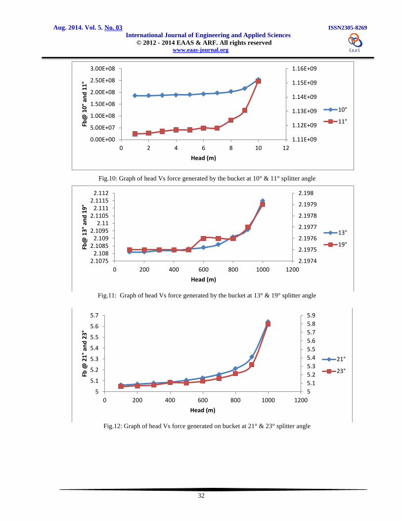
Fig.10: Graph of head Vs force generated by the bucket at 10° & 11° splitter angle
Fig.11: Graph of head Vs force generated by the bucket at 13° & 19° splitter angle
Fig.12: Graph of head Vs force generated on bucket at 21° & 23° splitter angle
1.11E+09
1.12E+09
1.13E+09
1.14E+09
1.15E+09
1.16E+09
0.00E+00
5.00E+07
1.00E+08
1.50E+08
2.00E+08
2.50E+08
3.00E+08
0 2 4 6 8 10 12
Fb@
10
° an
d 1
1°
Head (m)
10°
11°
2.1974
2.1975
2.1976
2.1977
2.1978
2.1979
2.198
2.10752.108
2.10852.109
2.10952.11
2.11052.111
2.11152.112
0 200 400 600 800 1000 1200
Fb@
13
° an
d 1
9°
Head (m)
13°
19°
5
5.1
5.2
5.3
5.4
5.5
5.6
5.7
5.8
5.9
5
5.1
5.2
5.3
5.4
5.5
5.6
5.7
0 200 400 600 800 1000 1200
Fb @
21
° an
d 2
3°
Head (m)
21°
23°
Aug. 2014. Vol. 5. No. 03 ISSN2305-8269
International Journal of Engineering and Applied Sciences © 2012 - 2014 EAAS & ARF. All rights reserved www.eaas-journal.org
33
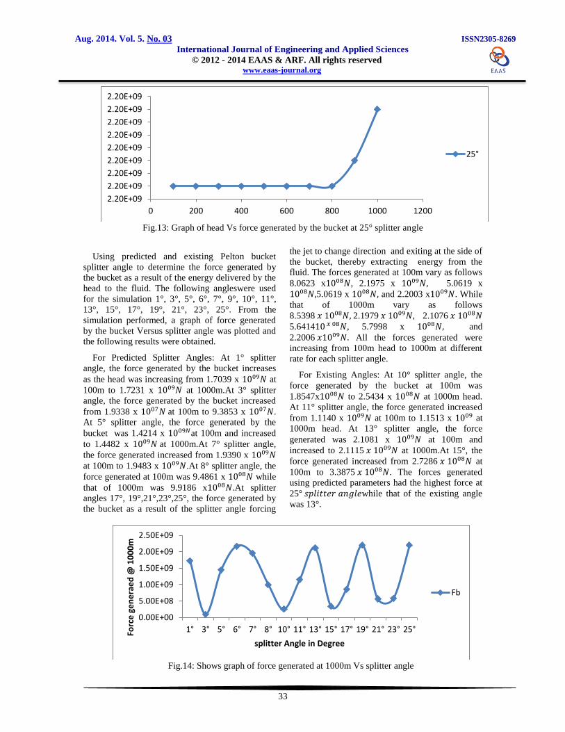
Fig.13: Graph of head Vs force generated by the bucket at 25° splitter angle
Using predicted and existing Pelton bucket
splitter angle to determine the force generated by
the bucket as a result of the energy delivered by the
head to the fluid. The following angleswere used
for the simulation 1°, 3°, 5°, 6°, 7°, 9°, 10°, 11°,
13°, 15°, 17°, 19°, 21°, 23°, 25°. From the
simulation performed, a graph of force generated
by the bucket Versus splitter angle was plotted and
the following results were obtained.
For Predicted Splitter Angles: At 1° splitter
angle, the force generated by the bucket increases
as the head was increasing from 1.7039 x at
100m to 1.7231 x at 1000m.At 3° splitter
angle, the force generated by the bucket increased
from 1.9338 x at 100m to 9.3853 x .
At 5° splitter angle, the force generated by the
bucket was 1.4214 x at 100m and increased
to 1.4482 x at 1000m.At 7° splitter angle,
the force generated increased from 1.9390 x
at 100m to 1.9483 x .At 8° splitter angle, the
force generated at 100m was 9.4861 x while
that of 1000m was 9.9186 x .At splitter
angles 17°, 19°,21°,23°,25°, the force generated by
the bucket as a result of the splitter angle forcing
the jet to change direction and exiting at the side of
the bucket, thereby extracting energy from the
fluid. The forces generated at 100m vary as follows
8.0623 x , 2.1975 x 5.0619 x
5.0619 x and 2.2003 x . While
that of 1000m vary as follows
8.5398 2.1979 2.1076
5.6414 , 5.7998 x and
2.2006 All the forces generated were
increasing from 100m head to 1000m at different
rate for each splitter angle.
For Existing Angles: At 10° splitter angle, the
force generated by the bucket at 100m was
1.8547x to 2.5434 x at 1000m head.
At 11° splitter angle, the force generated increased
from 1.1140 x at 100m to 1.1513 x at
1000m head. At 13° splitter angle, the force
generated was 2.1081 x at 100m and
increased to 2.1115 at 1000m.At 15°, the
force generated increased from 2.7286 at
100m to 3.3875 . The forces generated
using predicted parameters had the highest force at
25 while that of the existing angle
was 13°.
Fig.14: Shows graph of force generated at 1000m Vs splitter angle
2.20E+09
2.20E+09
2.20E+09
2.20E+09
2.20E+09
2.20E+09
2.20E+09
2.20E+09
2.20E+09
0 200 400 600 800 1000 1200
25°
0.00E+00
5.00E+08
1.00E+09
1.50E+09
2.00E+09
2.50E+09
1° 3° 5° 6° 7° 8° 10° 11° 13° 15° 17° 19° 21° 23° 25°Forc
e g
en
era
ed
@ 1
00
0m
splitter Angle in Degree
Fb
Aug. 2014. Vol. 5. No. 03 ISSN2305-8269
International Journal of Engineering and Applied Sciences © 2012 - 2014 EAAS & ARF. All rights reserved www.eaas-journal.org
34
Fig.14 shows the summation of forces generated
at 1000m head using both the predicted and already
existing splitter angles for pelton bucket. From the
reading we can conclude that the bucket generated
greater force at 25° followed by 6° 19° and 13°,
showing that the predicted angle could give a better
result compared to that of the existing angle, with
this some other splitter angles are recommended to
improve the power output of a pelton turbine.
3.1. Shaft Output due to the Existing and Predicted Splitter Angles obtained through Simulation
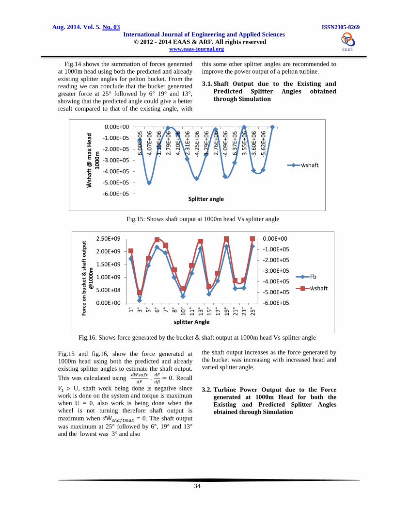
Fig.15: Shows shaft output at 1000m head Vs splitter angle
Fig.16: Shows force generated by the bucket & shaft output at 1000m head Vs splitter angle
Fig.15 and fig.16, show the force generated at
1000m head using both the predicted and already
existing splitter angles to estimate the shaft output.
This was calculated using
.
. Recall
U, shaft work being done is negative since
work is done on the system and torque is maximum
when U = 0, also work is being done when the
wheel is not turning therefore shaft output is
maximum when = 0. The shaft output
was maximum at 25° followed by 6°, 19° and 13°
and the lowest was 3° and also
the shaft output increases as the force generated by
the bucket was increasing with increased head and
varied splitter angle.
3.2. Turbine Power Output due to the Force
generated at 1000m Head for both the
Existing and Predicted Splitter Angles
obtained through Simulation
-6.00E+05
-5.00E+05
-4.00E+05
-3.00E+05
-2.00E+05
-1.00E+05
0.00E+00
6.0
0E+
05
-4.0
7E+
06
-1.1
9E+
06
2.7
9E+
06
4.2
0E+
06
-2.3
1E+
06
-4.2
5E+
06
1.7
9E+
06
2.7
6E+
06
-4.0
9E+
06
6.3
7E+
05
3.5
5E+
06
-3.6
0E+
06
-5.6
2E+
06
Ẇ
shaf
t @
max
He
ad
10
00
m
Splitter angle
ẇshaft
-6.00E+05
-5.00E+05
-4.00E+05
-3.00E+05
-2.00E+05
-1.00E+05
0.00E+00
0.00E+00
5.00E+08
1.00E+09
1.50E+09
2.00E+09
2.50E+09
1°
3°
5°
6°
7°
8°
10
°
11
°
13
°
15
°
17
°
19
°
21
°
23
°
25
°
Forc
e o
n b
uck
et
& s
haf
t o
utp
ut
@1
00
0m
splitter Angle
Fb
ẇshaft

Aug. 2014. Vol. 5. No. 03 ISSN2305-8269
International Journal of Engineering and Applied Sciences © 2012 - 2014 EAAS & ARF. All rights reserved www.eaas-journal.org
35
Fig.17: Graph of overall power output Vs bucket splitter angle
As the force generated by the bucket increases the
turbine power output also increases at different
splitter angles.
3.3. Turbine Power Output due to the Energy
delivered by the head to the Bucket Splitter
at 25 obtained through Simulation
Fig.18: Graph of Turbine power output Vs Head at 25 bucket splitter angle
As the head increases from 100 to 1000m, the
energy delivered to the turbine system also
increases thereby causing the turbine power output
to increase. Finally the investigation on the effect of
Head and bucket splitter angle on the power output
of a pelton turbine shows that angles 25°, 6°, 19°
and some other predicted splitter angle gave a
better result compared to that of the existing angle.
4. CONCLUSION
The pelton turbine operating on high head and
low flow with increased pressure condition
generated a power output which could be applied in
sitting a large hydro power plant while that of the
low head and high flow with decreased pressure
generated a lesser output and could be applied in
sitting a small MHPP.
Comparing the forces generated by the bucket for
both the existing splitter angle (10° - 15°) and
predicted splitter angle (1° -25°) operating on high
head and low flow head conditions, the result
shows that in addition to the existing splitter angle
(10° - 15°) three more angles have been
investigated to give maximum power. The angles
are 25°, 6°, and 19° in order of their maximum
generating power. Thus combining the existing and
predicted values, the following angles (25 , 6 ,
19 , 13 and 11 ) can be said to be suitable for
maximum power generation in a hydro turbine
application, in their order of maximum generating
power.
0
50000
100000
150000
25° 6° 19° 13° 11°
P(kW)@ 1000m
P(kW)@ 1000m
114000115000116000117000118000119000120000121000
0 200 400 600 800 1000 1200
Po
we
r o
utp
ut
fro
m t
urb
ine
(k
W)
Head (m)
P(kW)
P(kW)

Aug. 2014. Vol. 5. No. 03 ISSN2305-8269
International Journal of Engineering and Applied Sciences © 2012 - 2014 EAAS & ARF. All rights reserved www.eaas-journal.org
36
The operating condition for the pelton turbine in
the lab was low head and high flow with decreased
pressure, the force generated on the bucket surface
as the jet strike the splitter angle was maximum at
23° followed by 21° 15° 10° 3°. This result shows
that in addition to the existing splitter angle (10° -
15°) three more angles have been investigated to
give maximum power. The angles are 23°, 21°, and
3° in order of their maximum generating power.
For maximum efficiency, there is no reduction of
the relative velocity over the wheel and the bucket
deflection angle should not be more than 155 to
170 . To avoid the interference between the
oncoming and out coming jet and hence overall
efficiency would decrease.
REFERENCE
[1] Newman, Mark (2006). Study on a Renewable
Energy for sustainable future. Oxford: Oxford
university press.
[2] Thapa Bhola., Upadhyay Piyus, Gautem
Prakash (2006). Performance Analysis of
pelton turbine buckets Using Impact testing
and flow visualization techniques NHE.
Katthmandu University Journal of science,
Engineering and Technology Vol 5, No 2. Sept
2009, page 42 – 50.
[3] Zoppe B.J pellone C. (2006). Flow Analysis
inside pelton turbine bucket’’ Journal of turbo
machinery, Vol 4, page 128.
[4] Ainley, D.G and Matheson (1957).A Method
of performance Estimation G. C. R
for Axial flow turbines, Aero, Res.Council and
m. 2974.
[5] Rajput, R.K (1998). Fluid mechanics and
hydraulic Machines New Delhi S.Chend and
co. Ltd.
[6] Brekke, H. A general study of the design of
vertical pelton turbines. In turboinstitut (B.
Velensek and M. Bajd, 13-15 September
1984), B. Velensek and M. Bajd, Eds., vol. 1,
pp.383–397. Proceedings of the conference on
hydraulic machinery and flow measurements.
[7] Perrig, A., Farhat, M., Avellan, F., Parkinson,
E., Garcin, H., Bissel, C.,Valle, M., and Favre,
J. Numerical flow analysis in a pelton turbine
bucket. In Hydraulic Machinery and Systems
[49]. Proceedings of the 22nd IAHR
Symposium.
[8] Zhang, Zh., Muggli, F., Parkinson, E., and
Scha¨rer, Ch.(2000), Experimental
investigation of a low head jet flow at a model
nozzle of a Pelton turbine. Proceedings of the
11th International Seminar on Hydropower
Plants, Vienna, Austria, pp. 181–188.6.
[9] Ben M. Koons (2008).Mechanical Design on
pelton turbine for Rwanda Pico Hydro- Hydro
Project (Thayer School of Engineering
Dartmouth College.
[10] Richard L. Roberts on (August 8 2008).Ocean
Energy. Wentworth Institute of Technology
Senior Design Project, Mechanical
Engineering.