MODELING AND SIMULATION OF PLASMA PROCESSING: STATUS...
90
CECAM9801 MODELING AND SIMULATION OF PLASMA PROCESSING: STATUS AND DATABASE REQUIREMENTS Mark J. Kushner University of Illinois Department of Electrical and Computer Engineering Urbana, IL 61801 USA [email protected] http://uigelz.ece.uiuc.edu September 1998
Transcript of MODELING AND SIMULATION OF PLASMA PROCESSING: STATUS...
CECAM9801
MODELING AND SIMULATION OF PLASMA PROCESSING:STATUS AND DATABASE REQUIREMENTS
Mark J. KushnerUniversity of Illinois
Department of Electrical and Computer EngineeringUrbana, IL 61801 USA
[email protected] http://uigelz.ece.uiuc.edu
September 1998

AGENDA_______________________________________________
__________________University of Illinois
Optical and Discharge PhysicsCECAM9802
•• Introduction to plasma processing and plasma equipment modeling.
•• Background to initiatives in plasma modeling and database assessment
•• Examples of plasma equipment and process modeling
•• Assessment and needs in electron impact database
•• How good does the data need to be?
•• Concluding Remarks
UNIVERSITY OF ILLINOISOPTICAL AND DISCHARGE PHYSICS
MOORE’S LAW IN MICROELECTRONICSFABRICATION
UMINN9801
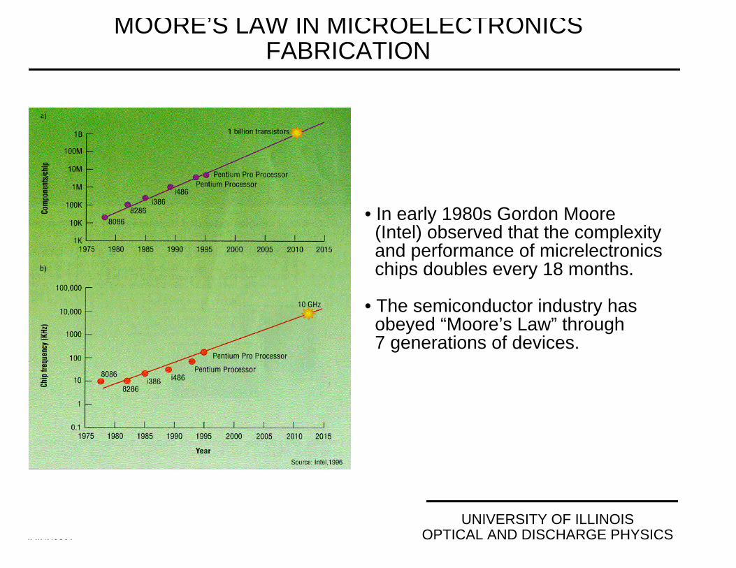
• In early 1980s Gordon Moore (Intel) observed that the complexity and performance of micrelectronics chips doubles every 18 months.
• The semiconductor industry has obeyed “Moore’s Law” through 7 generations of devices.

UNIVERSITY OF ILLINOISOPTICAL AND DISCHARGE PHYSICS
NATIONAL TECHNOLOGY ROADMAP FORSEMICONDUCTORS
UMINN9804
• The NTRS sets goals for the microelectronics fabrication industry for future generation of devices.
0.00
0.05
0.10
0.15
0.20
0.25
0.30
10
100
1000
104
1995 2000 2005 2010 2015YEAR OF FIRST PRODUCT SHIPMENT
SIZE
NUMBER
• Ref: “National Technology Roadmap for Semiconductors”, SIA, 1997.
• Feature sizes will continue to shrink with more transistors per chip while....
UNIVERSITY OF ILLINOISOPTICAL AND DISCHARGE PHYSICS
EVEN SMALLER DEVICES CAN BE BUILT...BUT THEY ALSO MUST BE MANUFACTURABLE
UMINN9803
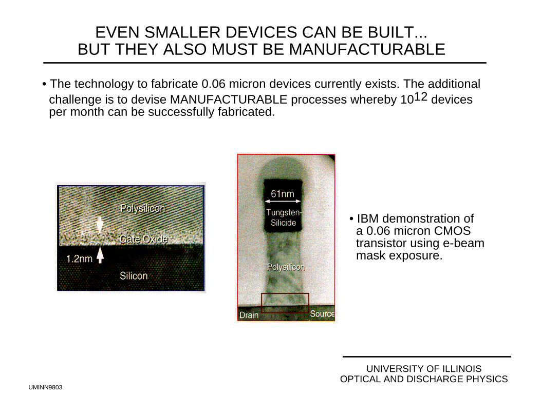
• The technology to fabricate 0.06 micron devices currently exists. The additional challenge is to devise MANUFACTURABLE processes whereby 1012 devices per month can be successfully fabricated.
• IBM demonstration of a 0.06 micron CMOS transistor using e-beam mask exposure.
INCREASED COMPLEXITY REQUIRES NEW SOLUTIONS:INTERCONNECT WIRING_______________________________________________
__________________University of Illinois
Optical and Discharge PhysicsCECAM9824
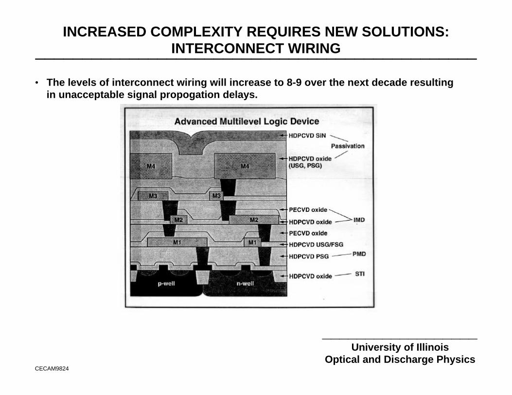
• The levels of interconnect wiring will increase to 8-9 over the next decade resultingin unacceptable signal propogation delays.
UNIVERSITY OF ILLINOISOPTICAL AND DISCHARGE PHYSICS
COPPER INTERCONNECT WIRING WITHLOW CAPACITANCE DIELECTRICS
UMINN9806
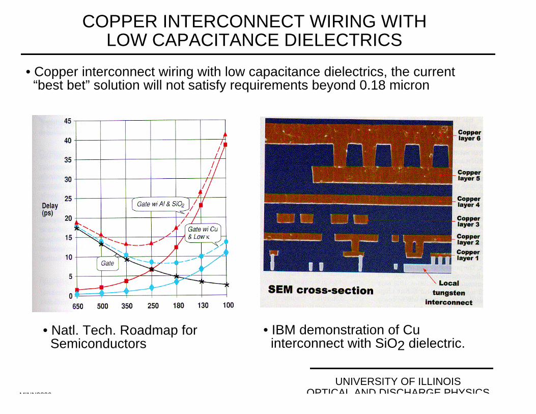
• Copper interconnect wiring with low capacitance dielectrics, the current “best bet” solution will not satisfy requirements beyond 0.18 micron
• IBM demonstration of Cu interconnect with SiO2 dielectric.
• Natl. Tech. Roadmap for Semiconductors
UNIVERSITY OF ILLINOISOPTICAL AND DISCHARGE PHYSICS
PLASMA PROCESSING FOR MICROELECTRONICS
CECAM98M15
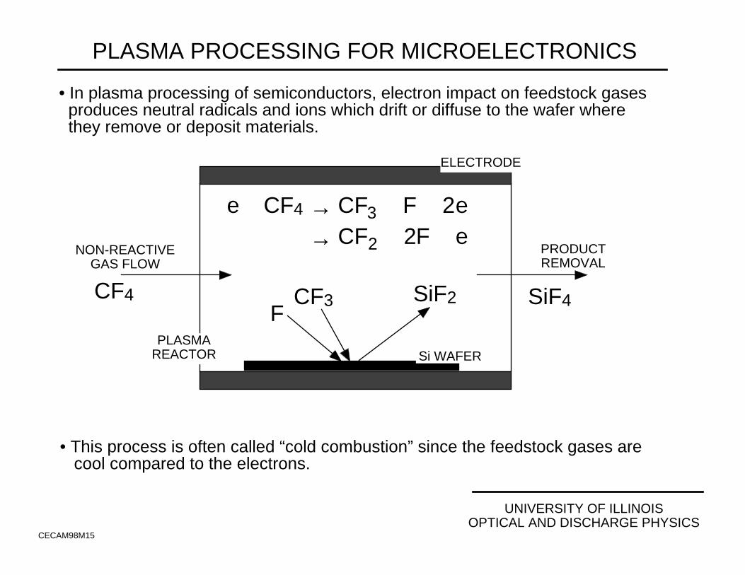
• In plasma processing of semiconductors, electron impact on feedstock gases produces neutral radicals and ions which drift or diffuse to the wafer where they remove or deposit materials.
• This process is often called “cold combustion” since the feedstock gases are cool compared to the electrons.
ELECTRODE
PLASMAREACTOR
NON-REACTIVEGAS FLOW
PRODUCTREMOVAL
e + CF4 → CF3+ + F + 2e
→ CF2 + 2F + e
Si WAFER
CF3+
FSiF2CF4 SiF4

UNIVERSITY OF ILLINOISOPTICAL AND DISCHARGE PHYSICSCECAM98M21
PLASMAS ARE ESSENTIAL FOR ECONOMICALLYFABRICATING FINE FEATURES IN MICROELECTRONICS
• In plasma processing, ions are accelerated nearly vertically into the wafer, thereby activating etch processes which produce straight walled, anisotropic features
POSITION
WAFER
SHEATH
+IONIONS
MASK
SiO2
Si
• Ion Assisted Etching • Neutral Dominated Etching
NEUTRALRADICALS
PHOTOGRAPHS OF PLASMA ETCHING TOOLS_______________________________________________
__________________University of Illinois
Optical and Discharge Physics
Photographs of:
Tegal Corp. Plasma Etching Tool
and
Applied Materials Decoupled Plasma Source
appear here.
COST OF FABRICATION FACILITIES_______________________________________________
__________________University of Illinois
Optical and Discharge PhysicsCECAM9827
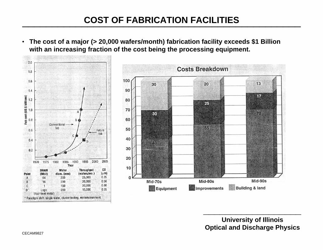
• The cost of a major (> 20,000 wafers/month) fabrication facility exceeds $1 Billionwith an increasing fraction of the cost being the processing equipment.
THE VIRTUAL FACTORY: A DESIGN PARADIGM_______________________________________________
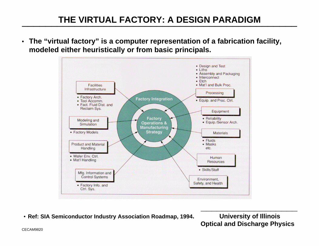
__________________•• Ref: SIA Semiconductor Industry Association Roadmap, 1994. University of Illinois
Optical and Discharge PhysicsCECAM9820
•• The “virtual factory” is a computer representation of a fabrication facility,modeled either heuristically or from basic principals.
UNIVERSITY OF ILLINOISOPTICAL AND DISCHARGE PHYSICS
COMPONENTS OF A PLASMAEQUIPMENT MODEL
S
S
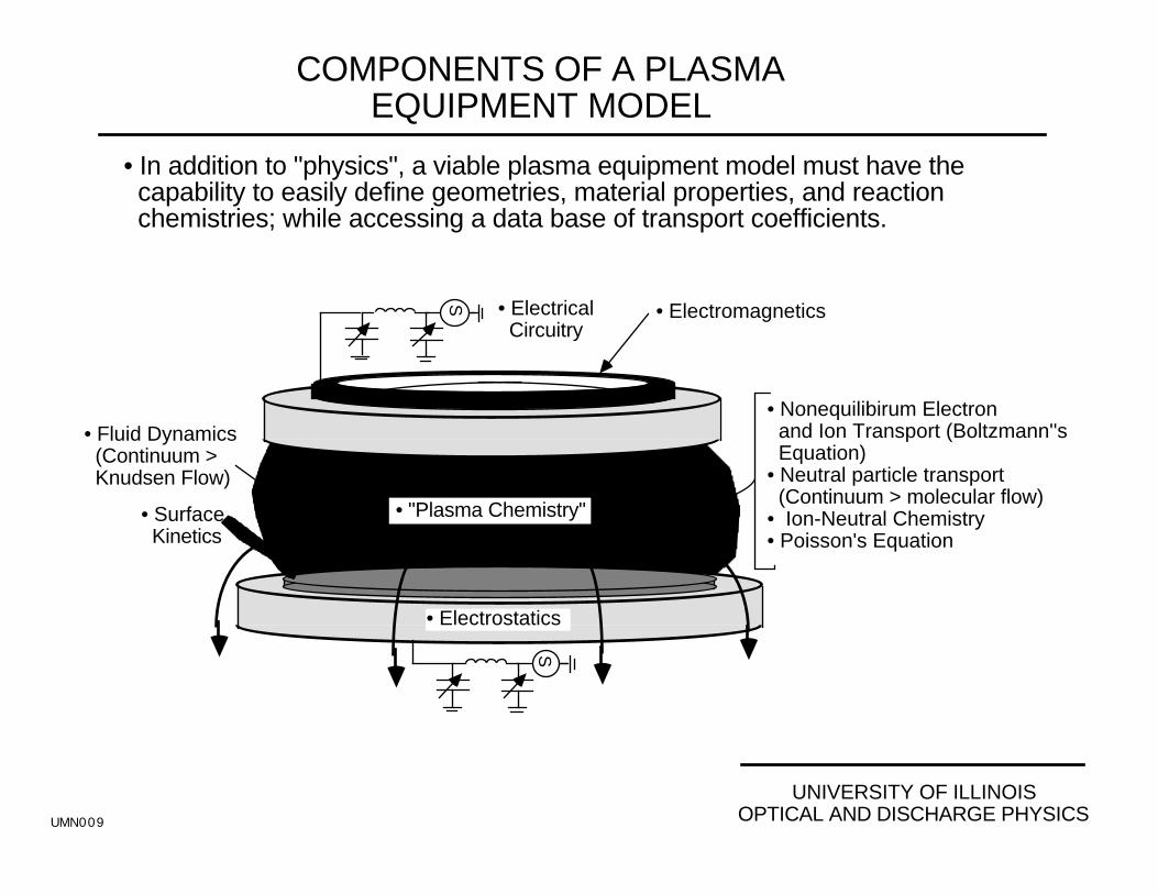
• Fluid Dynamics (Continuum > Knudsen Flow)
• Electromagnetics• Electrical Circuitry
• Surface Kinetics
• "Plasma Chemistry"
• Electrostatics
• Nonequilibirum Electron and Ion Transport (Boltzmann''s Equation)• Neutral particle transport (Continuum > molecular flow)• Ion-Neutral Chemistry• Poisson's Equation
• In addition to "physics", a viable plasma equipment model must have the capability to easily define geometries, material properties, and reaction chemistries; while accessing a data base of transport coefficients.
UMN009

UNIVERSITY OF ILLINOISOPTICAL AND DISCHARGE PHYSICS
SPATIAL SCALES IN PLASMA PROCESSING SPANMANY ORDERS OF MAGNITUDE
ICRP97M12
• EQUIPMENT SCALE (cm - 10s cm)Gas FlowHeat TransferPlasma TransportChemical Kinetics
PLASMA
WAFER
e + CF4 > CF3+ + F + 2e
• FEATURE SCALE” (10s nm - µm)Electron, Ion, Radical TransportPlasma Surface InteractionSurface chemistry
IONS
SHEATH0.1 - 0.5 µm
WAFER
• “TRANSITION SCALE” (10s -100s µm)Electron and Ion TransportSparse CollsionsElectrodynamics
WAFER
SHEATH
SUBSTRATE
10’s - 100s µm
IONS
PLASMA

NRC PANEL ON PLASMA PROCESSING OF MATERIALS_______________________________________________
__________________University of Illinois
Optical and Discharge PhysicsCECAM9814
•• 1991 United States NationalResearch Council (NRC) report"Plasma Processing: ScientificOpportunities and TechnologicalChallenges"
•• Evaluate impact of advances inlow temperature plasma scienceon material processing(microelectronics).
•• Identify key research problems inplasma physics, chemistry andsurface interactions.
•• Recommend means to bringstrengths of plasma sciencecommunity to address issues.
NRC PANEL ON PLASMA PROCESSING OF MATERIALS:FINDINGS AND RECOMMENDATIONS_______________________________________________
__________________University of Illinois
Optical and Discharge PhysicsCECAM9815
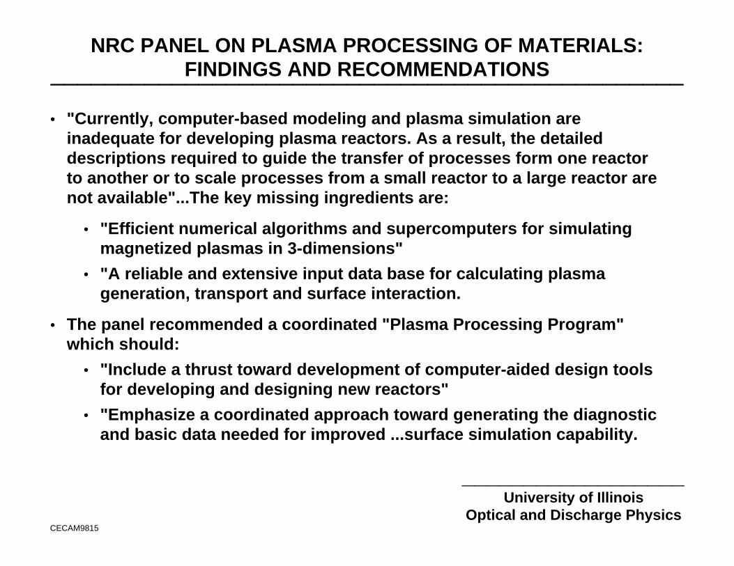
•• "Currently, computer-based modeling and plasma simulation areinadequate for developing plasma reactors. As a result, the detaileddescriptions required to guide the transfer of processes form one reactorto another or to scale processes from a small reactor to a large reactor arenot available"...The key missing ingredients are:
•• "Efficient numerical algorithms and supercomputers for simulatingmagnetized plasmas in 3-dimensions"
•• "A reliable and extensive input data base for calculating plasmageneration, transport and surface interaction.
•• The panel recommended a coordinated "Plasma Processing Program"which should:
•• "Include a thrust toward development of computer-aided design toolsfor developing and designing new reactors"
•• "Emphasize a coordinated approach toward generating the diagnosticand basic data needed for improved ...surface simulation capability.

NRC PANEL ON PLASMA PROCESSING OF MATERIALS:IMPACT ON US RESEARCH_______________________________________________
__________________University of Illinois
Optical and Discharge PhysicsCECAM9816
• Recommendations of NRC PPPM created a great deal of excitment in theUS plasma science community.
•• Microelectronics industry realized the need for improved simulationcapability redirected emphasis in basic science expenditures.
•• Downturn in fusion and US defense funding redirected many largeplasma research programs (Naval Research Lab, Lawrence LivermoreNational Lab, Sandia National Lab, NASA)
•• US Department of Energy and Sematch launched CRADAs(Cooperative Research and Developement Agreements) in plasmamodeling and simulation.
•• High Performance Computing and Communications (HPCC) initiativesparked coordinated cross disciplinary activities.
•• Great strides were made in development of plasma equipment models,however basic data needs were not emphasized.
NRC PANEL ON DATABASE NEEDS FOR MODELING ANDSIMULATION OF PLASMA PROCESSING_______________________________________________
__________________University of Illinois
Optical and Discharge PhysicsCECAM9817
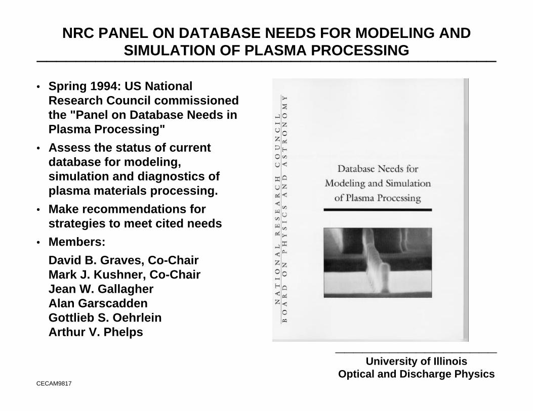
•• Spring 1994: US NationalResearch Council commissionedthe "Panel on Database Needs inPlasma Processing"
•• Assess the status of currentdatabase for modeling,simulation and diagnostics ofplasma materials processing.
•• Make recommendations forstrategies to meet cited needs
•• Members:
David B. Graves, Co-Chair Mark J. Kushner, Co-Chair Jean W. Gallagher Alan Garscadden Gottlieb S. Oehrlein Arthur V. Phelps
PANEL ON DATABASE NEEDS: RECOMMENDATIONS_______________________________________________
__________________University of Illinois
Optical and Discharge PhysicsCECAM9818
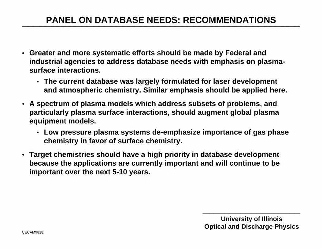
•• Greater and more systematic efforts should be made by Federal andindustrial agencies to address database needs with emphasis on plasma-surface interactions.
•• The current database was largely formulated for laser developmentand atmospheric chemistry. Similar emphasis should be applied here.
•• A spectrum of plasma models which address subsets of problems, andparticularly plasma surface interactions, should augment global plasmaequipment models.
•• Low pressure plasma systems de-emphasize importance of gas phasechemistry in favor of surface chemistry.
•• Target chemistries should have a high priority in database developmentbecause the applications are currently important and will continue to beimportant over the next 5-10 years.
TARGET GASES FOR PRIORITY DATABASE DEVELOPMENT_______________________________________________
__________________University of Illinois
Optical and Discharge PhysicsCECAM9819
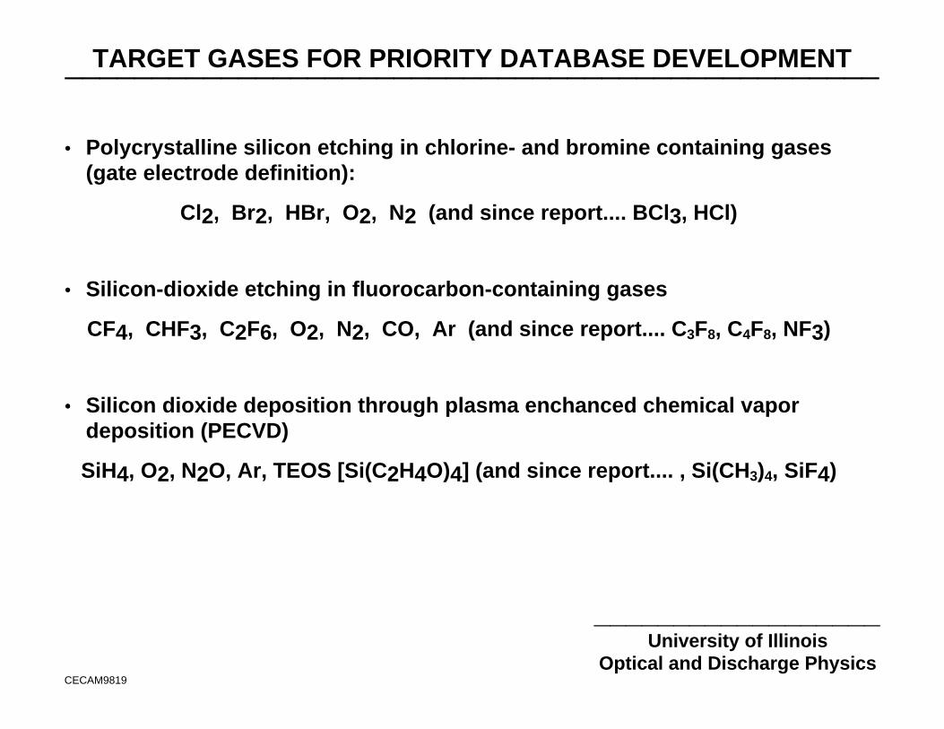
•• Polycrystalline silicon etching in chlorine- and bromine containing gases(gate electrode definition):
Cl2, Br2, HBr, O2, N2 (and since report.... BCl3, HCl)
•• Silicon-dioxide etching in fluorocarbon-containing gases
CF4, CHF3, C2F6, O2, N2, CO, Ar (and since report.... C3F8, C4F8, NF3)
•• Silicon dioxide deposition through plasma enchanced chemical vapordeposition (PECVD)
SiH4, O2, N2O, Ar, TEOS [Si(C2H4O)4] (and since report.... , Si(CH3)4, SiF4)
3-D PIC RIE
UNIVERSITY OF ILLINOISOPTICAL AND DISCHARGE PHYSICS
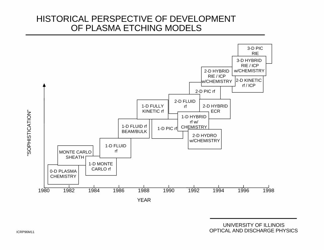
HISTORICAL PERSPECTIVE OF DEVELOPMENTOF PLASMA ETCHING MODELS
ICRP96M11
"SO
PH
IST
ICA
TIO
N"
0-D PLASMACHEMISTRY
1-D MONTECARLO rf
MONTE CARLOSHEATH
1-D FLUIDrf
1-D FLUID rfBEAM/BULK
1-D FULLYKINETIC rf
1-D PIC rf
2-D FLUIDrf
2-D PIC rf
2-D HYBRIDECR
2-D HYBRIDRIE / ICP
w/CHEMISTRY 2-D KINETICrf / ICP
1-D HYBRIDrf w/
CHEMISTRY
2-D HYDROw/CHEMISTRY
3-D HYBRID RIE / ICP
w/CHEMISTRY
1980 1982 1984 1986 1988 1990 1992 1994 1996
YEAR
1998
UNIVERSITY OF ILLINOISOPTICAL AND DISCHARGE PHYSICS
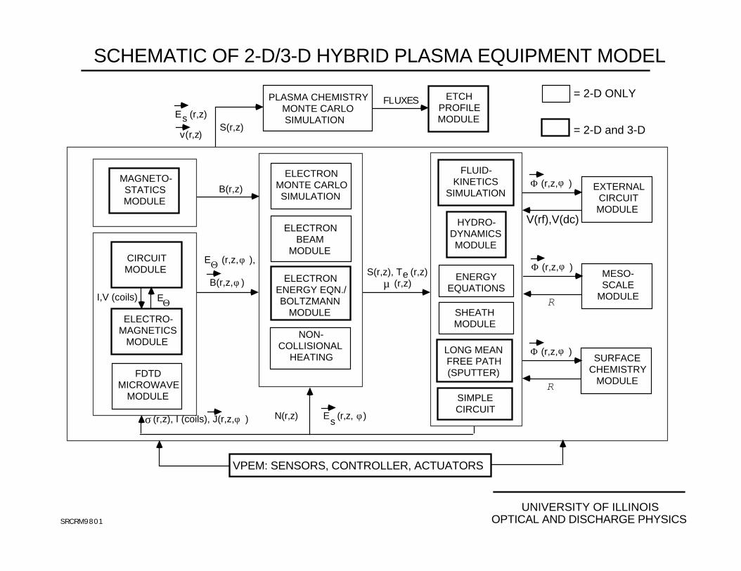
SCHEMATIC OF 2-D/3-D HYBRID PLASMA EQUIPMENT MODEL
SRCRM9801
S(r,z)E (r,z)s
v(r,z)
PLASMA CHEMISTRY MONTE CARLO SIMULATION
ETCHPROFILEMODULE
FLUXES
E (r,z, ),
B(r,z, )
Θ φ
φ
ELECTRO-MAGNETICS
MODULE
CIRCUITMODULE
I,V (coils) EΘ
S(r,z), T (r,z) (r,z)µ
e
FLUID-KINETICS
SIMULATION
HYDRO-DYNAMICSMODULE
ENERGYEQUATIONS
SHEATHMODULE
N(r,z) E (r,z, )s
φ(r,z), I (coils), J(r,z, )σ φ
ELECTRONBEAM
MODULE
ELECTRONMONTE CARLOSIMULATION
ELECTRONENERGY EQN./BOLTZMANN
MODULE
NON-COLLISIONAL
HEATINGLONG MEANFREE PATH(SPUTTER)
SIMPLECIRCUIT
MAGNETO-STATICSMODULE
B(r,z)
= 2-D ONLY
= 2-D and 3-D
EXTERNALCIRCUITMODULE
MESO-SCALE
MODULE
(r,z, )φΦ
R
(r,z, )φΦ
V(rf),V(dc)
VPEM: SENSORS, CONTROLLER, ACTUATORS
SURFACECHEMISTRY
MODULE
(r,z, )φΦ
RFDTD
MICROWAVEMODULE
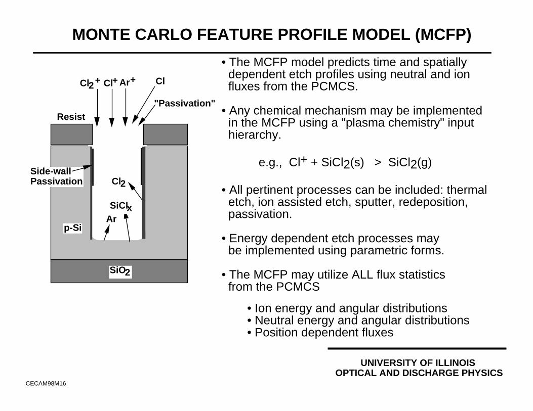
• The MCFP model predicts time and spatially dependent etch profiles using neutral and ion fluxes from the PCMCS.
• Any chemical mechanism may be implemented in the MCFP using a "plasma chemistry" input hierarchy.
e.g., Cl+ + SiCl2(s) > SiCl2(g)
• All pertinent processes can be included: thermal etch, ion assisted etch, sputter, redeposition, passivation.
• Energy dependent etch processes may be implemented using parametric forms.
• The MCFP may utilize ALL flux statistics from the PCMCS
• Ion energy and angular distributions• Neutral energy and angular distributions• Position dependent fluxes
MONTE CARLO FEATURE PROFILE MODEL (MCFP)
Resist
p-Si
SiO2
Cl
Ar
Cl2
Cl+
UNIVERSITY OF ILLINOISOPTICAL AND DISCHARGE PHYSICS
CECAM98M16
SiClx
"Passivation"
Side-wallPassivation
Ar+Cl2+
UNIVERSITY OF ILLINOISOPTICAL AND DISCHARGE PHYSICSCECAM98M17
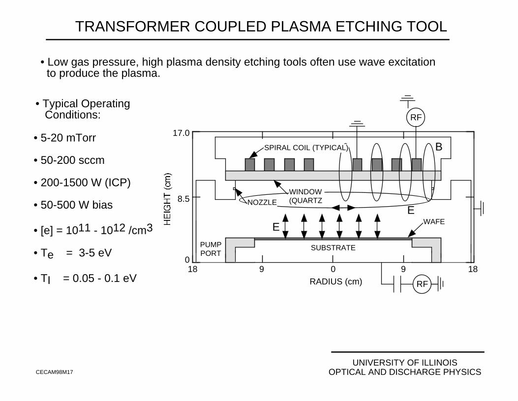
TRANSFORMER COUPLED PLASMA ETCHING TOOL
• Typical Operating Conditions:
• 5-20 mTorr
• 50-200 sccm
• 200-1500 W (ICP)
• 50-500 W bias
• [e] = 1011 - 1012 /cm3
• Te = 3-5 eV
• TI = 0.05 - 0.1 eV RADIUS (cm)
0
8.5
17.0
PUMPPORT
WAFE
SUBSTRATE
RF
RF
18 9 0 9 18
B
WINDOW(QUARTZNOZZLE
E
E
SPIRAL COIL (TYPICAL)
• Low gas pressure, high plasma density etching tools often use wave excitation to produce the plasma.
UNIVERSITY OF ILLINOISOPTICAL AND DISCHARGE PHYSICS
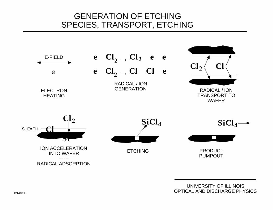
GENERATION OF ETCHINGSPECIES, TRANSPORT, ETCHING
ION ACCELERATIONINTO WAFER
------RADICAL ADSORPTION
ETCHING PRODUCTPUMPOUT
e + Cl2 → Cl + Cl + e e + Cl2 → Cl2
+ + e + eE-FIELD
e
ELECTRONHEATING
RADICAL / IONGENERATION RADICAL / ION
TRANSPORT TOWAFER
ClCl2+
SiCl4
ClCl2
+
SHEATH
Si
SiCl4
UMN001
UNIVERSITY OF ILLINOISOPTICAL AND DISCHARGE PHYSICS
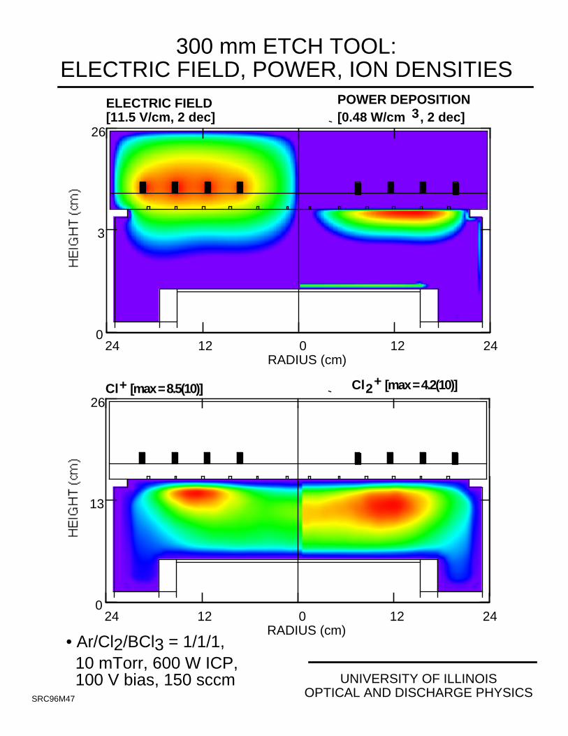
300 mm ETCH TOOL:ELECTRIC FIELD, POWER, ION DENSITIES
24 2412 120RADIUS (cm)
0
13
26
ELECTRIC FIELD[11.5 V/cm, 2 dec]
POWER DEPOSITION[0.48 W/cm 3, 2 dec]
• Ar/Cl2/BCl3 = 1/1/1, 10 mTorr, 600 W ICP, 100 V bias, 150 sccm
24 2412 120RADIUS (cm)
0
13
26Cl+ [max = 8.5(10)] Cl2+ [max = 4.2(10)]
SRC96M47
UNIVERSITY OF ILLINOISOPTICAL AND DISCHARGE PHYSICS
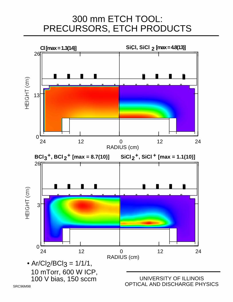
300 mm ETCH TOOL:PRECURSORS, ETCH PRODUCTS
• Ar/Cl2/BCl3 = 1/1/1, 10 mTorr, 600 W ICP, 100 V bias, 150 sccm
24 2412 120RADIUS (cm)
0
13
26Cl [max = 1.3(14)] SiCl, SiCl 2 [max = 4.8(13)]
24 2412 120RADIUS (cm)
0
13
26BCl3+, BCl 2+ [max = 8.7(10)] SiCl2+, SiCl + [max = 1.1(10)]
SRC96M98
UNIVERSITY OF ILLINOISOPTICAL AND DISCHARGE PHYSICS
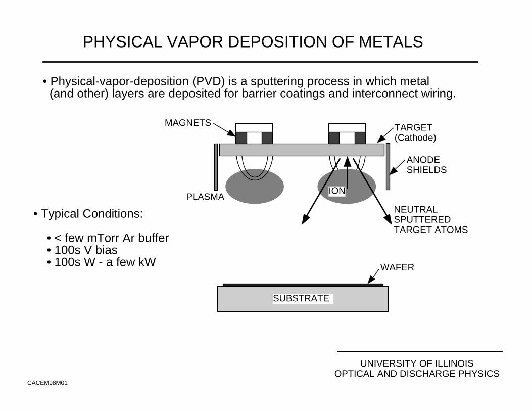
PHYSICAL VAPOR DEPOSITION OF METALS
CACEM98M01
• Physical-vapor-deposition (PVD) is a sputtering process in which metal (and other) layers are deposited for barrier coatings and interconnect wiring.
• Typical Conditions: • < few mTorr Ar buffer • 100s V bias • 100s W - a few kW
TARGET(Cathode)
MAGNETS
ANODESHIELDS
PLASMAION
NEUTRALSPUTTEREDTARGET ATOMS
SUBSTRATE
WAFER
UNIVERSITY OF ILLINOISOPTICAL AND DISCHARGE PHYSICS
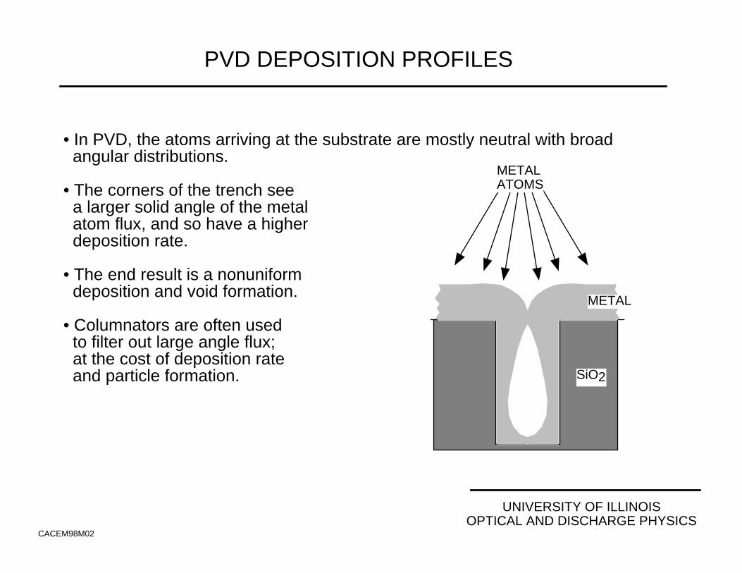
PVD DEPOSITION PROFILES
CACEM98M02
• In PVD, the atoms arriving at the substrate are mostly neutral with broad angular distributions.
• The corners of the trench see a larger solid angle of the metal atom flux, and so have a higher deposition rate.
• The end result is a nonuniform deposition and void formation.
• Columnators are often used to filter out large angle flux; at the cost of deposition rate and particle formation.
METAL
SiO2
METALATOMS
UNIVERSITY OF ILLINOISOPTICAL AND DISCHARGE PHYSICS
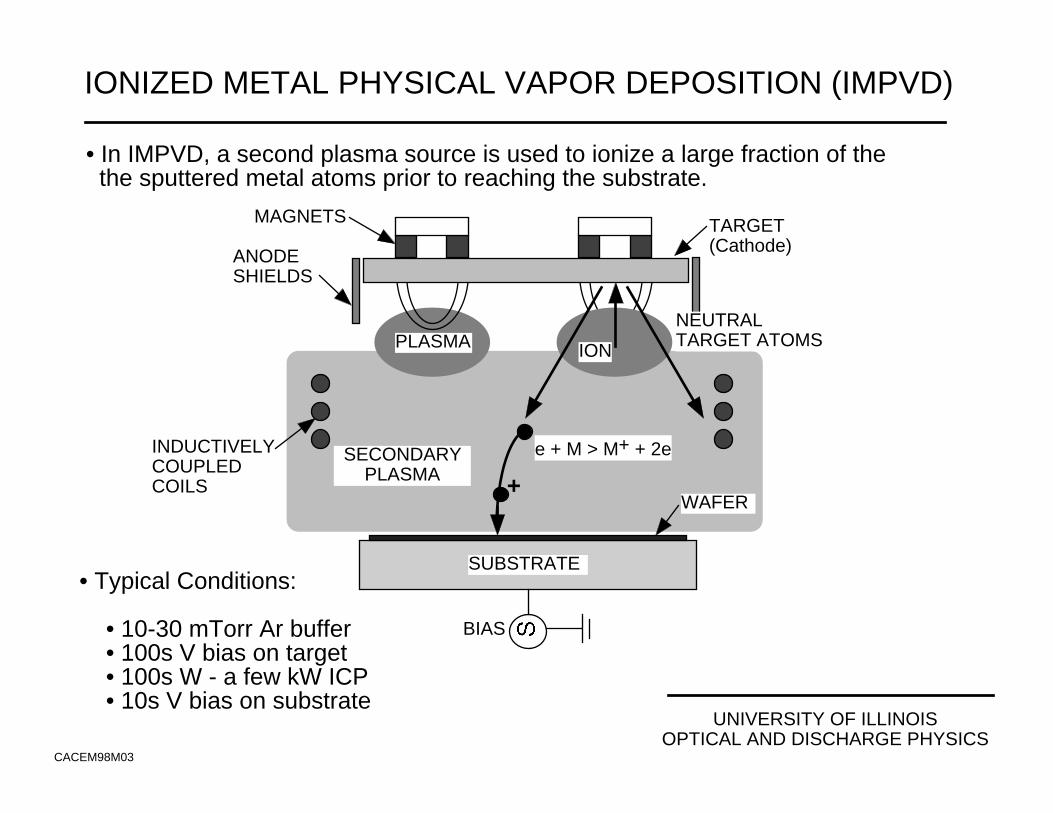
IONIZED METAL PHYSICAL VAPOR DEPOSITION (IMPVD)
CACEM98M03
• In IMPVD, a second plasma source is used to ionize a large fraction of the the sputtered metal atoms prior to reaching the substrate.
• Typical Conditions: • 10-30 mTorr Ar buffer • 100s V bias on target • 100s W - a few kW ICP • 10s V bias on substrate
TARGET(Cathode)
MAGNETS
ANODESHIELDS
PLASMA ION
WAFER
INDUCTIVELYCOUPLEDCOILS
SUBSTRATE
SECONDARYPLASMA
BIAS
e + M > M+ + 2e
NEUTRALTARGET ATOMS
+
UNIVERSITY OF ILLINOISOPTICAL AND DISCHARGE PHYSICS
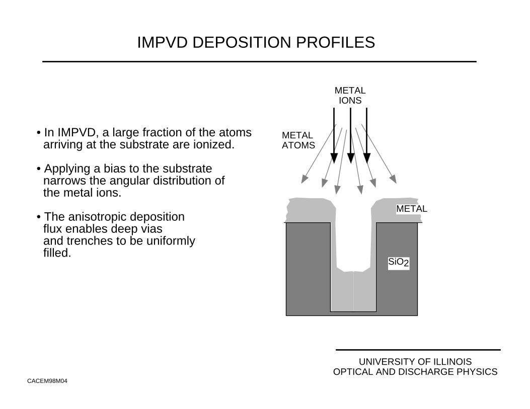
IMPVD DEPOSITION PROFILES
CACEM98M04
• In IMPVD, a large fraction of the atoms arriving at the substrate are ionized.
• Applying a bias to the substrate narrows the angular distribution of the metal ions.
• The anisotropic deposition flux enables deep vias and trenches to be uniformly filled.
SiO2
METALATOMS
METALIONS
METAL
UNIVERSITY OF ILLINOISOPTICAL AND DISCHARGE PHYSICS
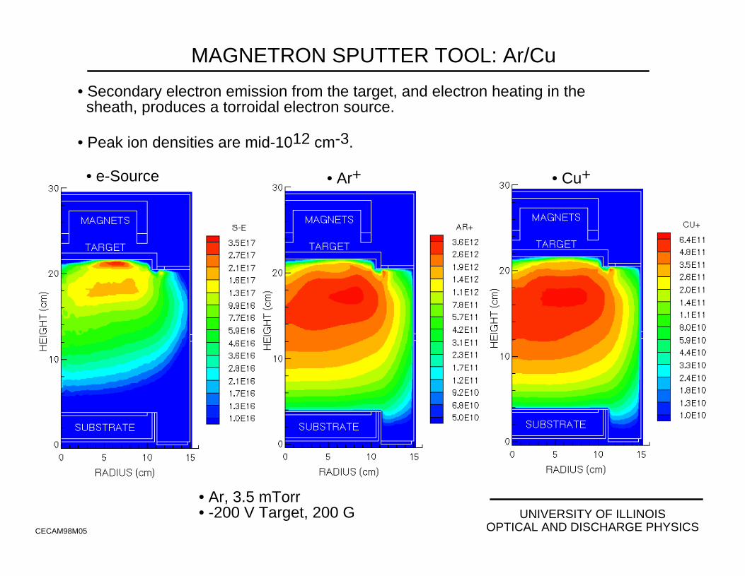
MAGNETRON SPUTTER TOOL: Ar/Cu
CECAM98M05
• Ar, 3.5 mTorr• -200 V Target, 200 G
• Secondary electron emission from the target, and electron heating in the sheath, produces a torroidal electron source.
• Peak ion densities are mid-1012 cm-3.
• e-Source • Ar+ • Cu+
UNIVERSITY OF ILLINOISOPTICAL AND DISCHARGE PHYSICS
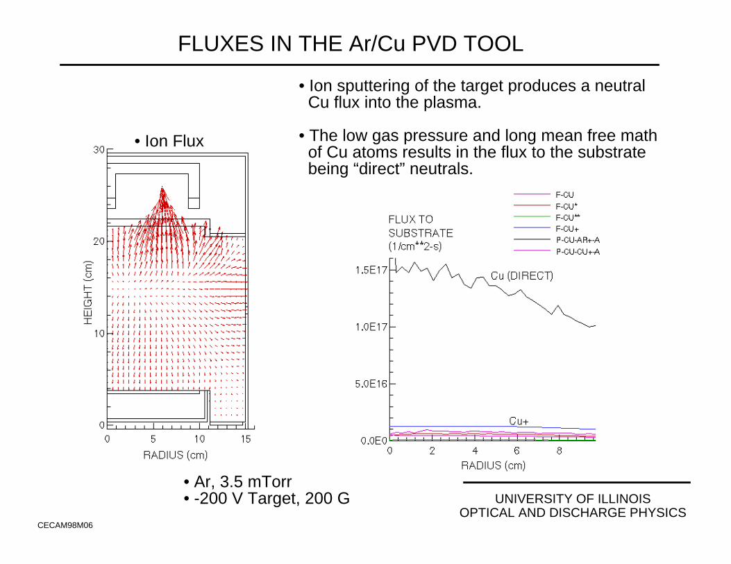
FLUXES IN THE Ar/Cu PVD TOOL
CECAM98M06
• Ar, 3.5 mTorr• -200 V Target, 200 G
• Ion Flux
• Ion sputtering of the target produces a neutral Cu flux into the plasma.
• The low gas pressure and long mean free math of Cu atoms results in the flux to the substrate being “direct” neutrals.
UNIVERSITY OF ILLINOISOPTICAL AND DISCHARGE PHYSICS
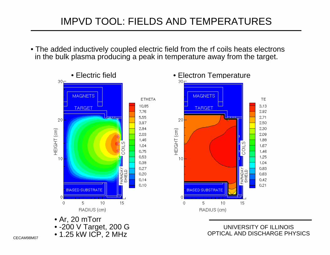
IMPVD TOOL: FIELDS AND TEMPERATURES
CECAM98M07
• Ar, 20 mTorr• -200 V Target, 200 G• 1.25 kW ICP, 2 MHz
• The added inductively coupled electric field from the rf coils heats electrons in the bulk plasma producing a peak in temperature away from the target.
• Electron Temperature• Electric field
UNIVERSITY OF ILLINOISOPTICAL AND DISCHARGE PHYSICS
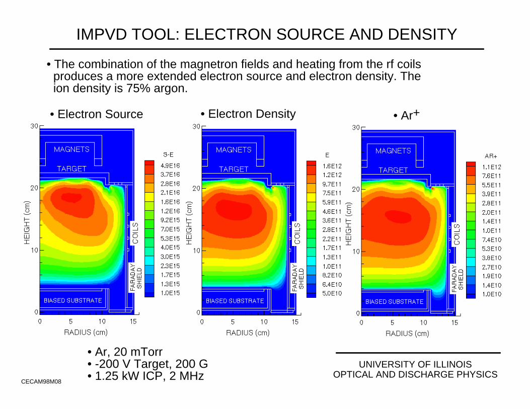
IMPVD TOOL: ELECTRON SOURCE AND DENSITY
CECAM98M08
• Ar, 20 mTorr• -200 V Target, 200 G• 1.25 kW ICP, 2 MHz
• The combination of the magnetron fields and heating from the rf coils produces a more extended electron source and electron density. The ion density is 75% argon.
• Electron Density• Electron Source • Ar+
UNIVERSITY OF ILLINOISOPTICAL AND DISCHARGE PHYSICS
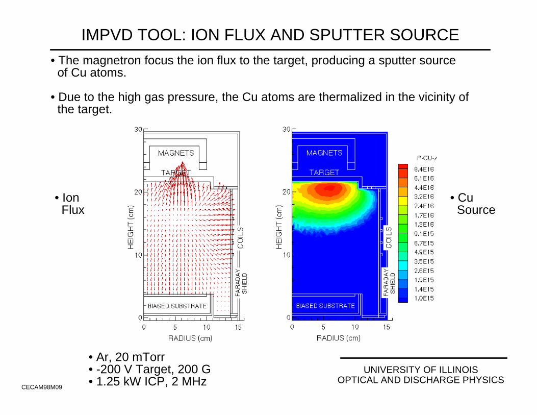
IMPVD TOOL: ION FLUX AND SPUTTER SOURCE
CECAM98M09
• Ar, 20 mTorr• -200 V Target, 200 G• 1.25 kW ICP, 2 MHz
• The magnetron focus the ion flux to the target, producing a sputter source of Cu atoms.
• Due to the high gas pressure, the Cu atoms are thermalized in the vicinity of the target.
• Cu Source
• Ion Flux
UNIVERSITY OF ILLINOISOPTICAL AND DISCHARGE PHYSICS
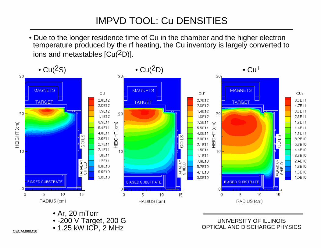
IMPVD TOOL: Cu DENSITIES
CECAM98M10
• Ar, 20 mTorr• -200 V Target, 200 G• 1.25 kW ICP, 2 MHz
• Due to the longer residence time of Cu in the chamber and the higher electron temperature produced by the rf heating, the Cu inventory is largely converted to ions and metastables [Cu(2D)].
• Cu(2S) • Cu(2D) • Cu+
UNIVERSITY OF ILLINOISOPTICAL AND DISCHARGE PHYSICS
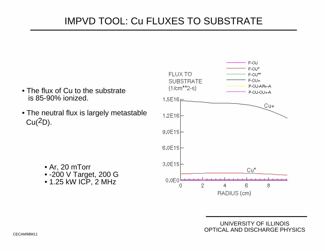
IMPVD TOOL: Cu FLUXES TO SUBSTRATE
CECAM98M11
• Ar, 20 mTorr• -200 V Target, 200 G• 1.25 kW ICP, 2 MHz
• The flux of Cu to the substrate is 85-90% ionized.
• The neutral flux is largely metastable Cu(2D).
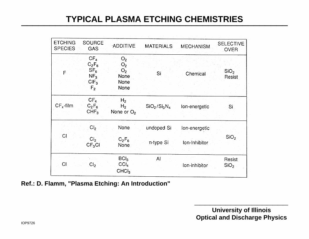
TYPICAL PLASMA ETCHING CHEMISTRIES_______________________________________________
__________________University of Illinois
Optical and Discharge PhysicsIOP9726
Ref.: D. Flamm, "Plasma Etching: An Introduction"
UNIVERSITY OF ILLINOISOPTICAL AND DISCHARGE PHYSICS
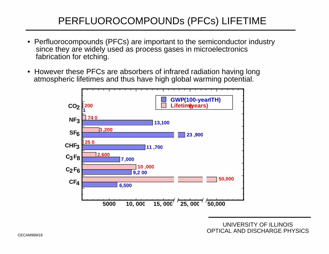
PERFLUOROCOMPOUNDs (PFCs) LIFETIME
CECAM98M18
• Perfluorocompounds (PFCs) are important to the semiconductor industry since they are widely used as process gases in microelectronics fabrication for etching.
• However these PFCs are absorbers of infrared radiation having long atmospheric lifetimes and thus have high global warming potential.
GWP (100-year ITH)Lifetime (years)
CF4
C2F6
C3F8
CHF3
SF6
NF3
CO2
5000 10, 000 15, 000 25, 000 50,000
6,50050,000
9,2 0010 ,000
2,6007 ,000
11 ,70025 0
23 ,9003 ,200
13,10074 0
2001

UNIVERSITY OF ILLINOISOPTICAL AND DISCHARGE PHYSICS
EXAMPLE OF DATABASE NEEDS:Ar/CF4 PLASMA ETCHING AND ABATEMENT
DAMOPM9802
• Plasma etching of Si and SiO2 typically use PFCs, greenhouse gases with large Global Warming Potential.
• Post-etch chamber abatement of PFCs is being investigated using downstream “burnboxes” with O2 injection to oxidize PFCs to easily scrubable compounds.
• Test conditions:
Etch Chamber:
13.56 MHz ICP reactor Ar/CF4 at 10 mTorr. Burn-Box:
13.56 MHz ICP reactorEffluent + O2 injection150 mTorr
Plasma “Burn-Box”
Plasma EtchingChamber
Wafer
Coils
O2
Coils
Showerhead Nozzle (Ar /CF4)
Turbopump
UNIVERSITY OF ILLINOISOPTICAL AND DISCHARGE PHYSICS
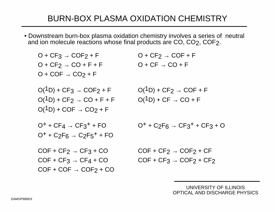
BURN-BOX PLASMA OXIDATION CHEMISTRY
DAMOP98M03
O + CF3 → COF2 + F O + CF2 → COF + F
O + CF2 → CO + F + F O + CF → CO + F
O + COF → CO2 + F
O(1D) + CF3 → COF2 + F O(1D) + CF2 → COF + F
O(1D) + CF2 → CO + F + F O(1D) + CF → CO + F
O(1D) + COF → CO2 + F
O+ + CF4 → CF3+ + FO O+ + C2F6 → CF3+ + CF3 + O
O+ + C2F6 → C2F5+ + FO
COF + CF2 → CF3 + CO COF + CF2 → COF2 + CF
COF + CF3 → CF4 + CO COF + CF3 → COF2 + CF2
COF + COF → COF2 + CO
• Downstream burn-box plasma oxidation chemistry involves a series of neutral and ion molecule reactions whose final products are CO, CO2, COF2.
UNIVERSITY OF ILLINOISOPTICAL AND DISCHARGE PHYSICS
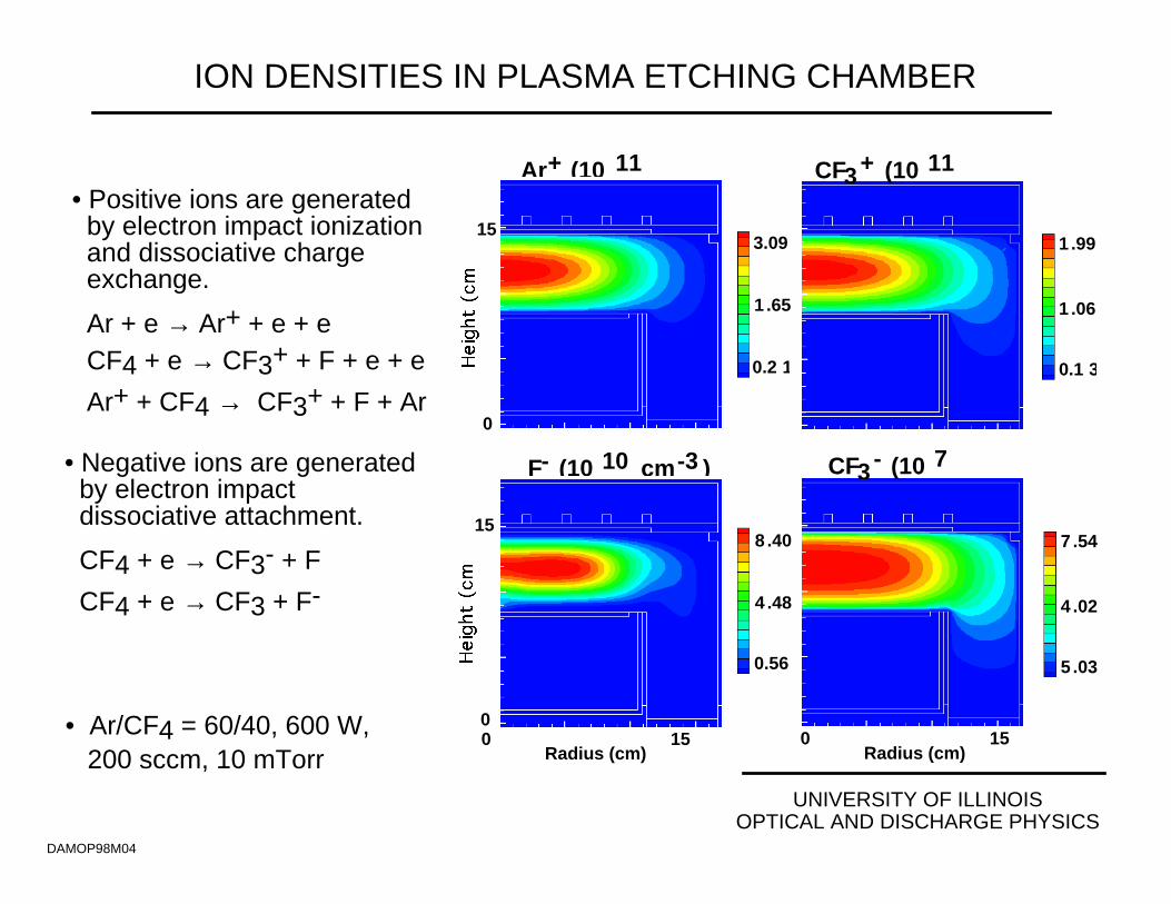
ION DENSITIES IN PLASMA ETCHING CHAMBER
DAMOP98M04
3.09
1 .65
0.2 1
Ar+ (10 11
15
0
150 Radius (cm)
8 .40
4 .48
0.56
F- (10 10 cm-3 )
15
0
1 .99
1 .06
0.1 3
CF3+ (10 11
7 .54
4 .02
5 .03
CF3- (10 7
150 Radius (cm)
• Positive ions are generated by electron impact ionization and dissociative charge exchange.
Ar + e → Ar+ + e + e CF4 + e → CF3+ + F + e + e
Ar+ + CF4 → CF3+ + F + Ar • Negative ions are generated by electron impact dissociative attachment.
CF4 + e → CF3- + F
CF4 + e → CF3 + F-
• Ar/CF4 = 60/40, 600 W, 200 sccm, 10 mTorr
UNIVERSITY OF ILLINOISOPTICAL AND DISCHARGE PHYSICS
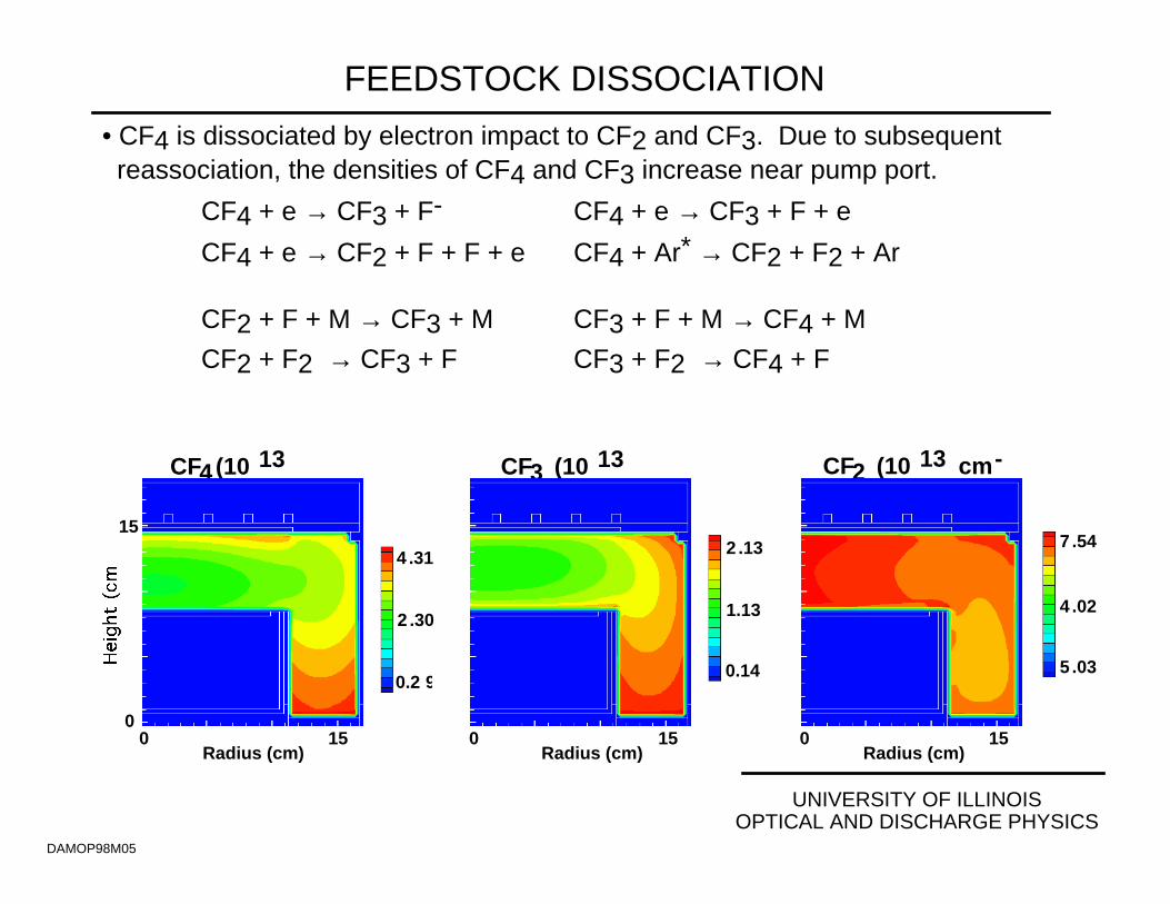
FEEDSTOCK DISSOCIATION
DAMOP98M05
4 .31
2 .30
0.2 9
CF4(10 13
15
0150
Radius (cm)
2 .13
1.13
0.14
CF3 (10 13
7 .54
4 .02
5 .03
CF2 (10 13 cm-
150 Radius (cm)
• CF4 is dissociated by electron impact to CF2 and CF3. Due to subsequent reassociation, the densities of CF4 and CF3 increase near pump port.
CF4 + e → CF3 + F- CF4 + e → CF3 + F + e
CF4 + e → CF2 + F + F + e CF4 + Ar* → CF2 + F2 + Ar
CF2 + F + M → CF3 + M CF3 + F + M → CF4 + M
CF2 + F2 → CF3 + F CF3 + F2 → CF4 + F
150 Radius (cm)

UNIVERSITY OF ILLINOISOPTICAL AND DISCHARGE PHYSICS
PFC GENERATION IN ETCHING CHAMBER
DAMOP98M06
• PFCs are generated as by products of the dissociation of feedstock gases. The majority of PFC generation is through wall reactions.
CF3 + CF3 + M → C2F6 + M CF3 + CF3 → C2F6 (at surface)
CF2 + CF3 + M → C2F5 + M CF2 + CF2 → C2F4 (at surface)
CF2 + F + M → CF3 + M
150 Radius (cm)
2 .97
1.59
0.20
C2F6 (10 12
1 .27
6 .75
8 .44
C2F5 (10 12
150 Radius (cm)
1 .10
0 .58
0.07
C2F4(10 12
15
0150
Radius (cm)
UNIVERSITY OF ILLINOISOPTICAL AND DISCHARGE PHYSICS
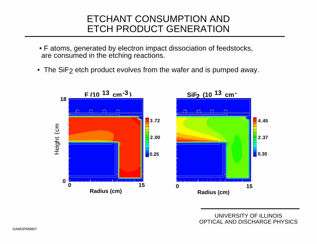
ETCHANT CONSUMPTION ANDETCH PRODUCT GENERATION
DAMOPM9807
• F atoms, generated by electron impact dissociation of feedstocks, are consumed in the etching reactions.
• The SiF2 etch product evolves from the wafer and is pumped away.
4 .45
2 .37
0.30
SiF2 (10 13 cm-
3 .72
2 .00
0.25
F (10 13 cm-3 )18
0150
Radius (cm)150
Radius (cm)
UNIVERSITY OF ILLINOISOPTICAL AND DISCHARGE PHYSICS
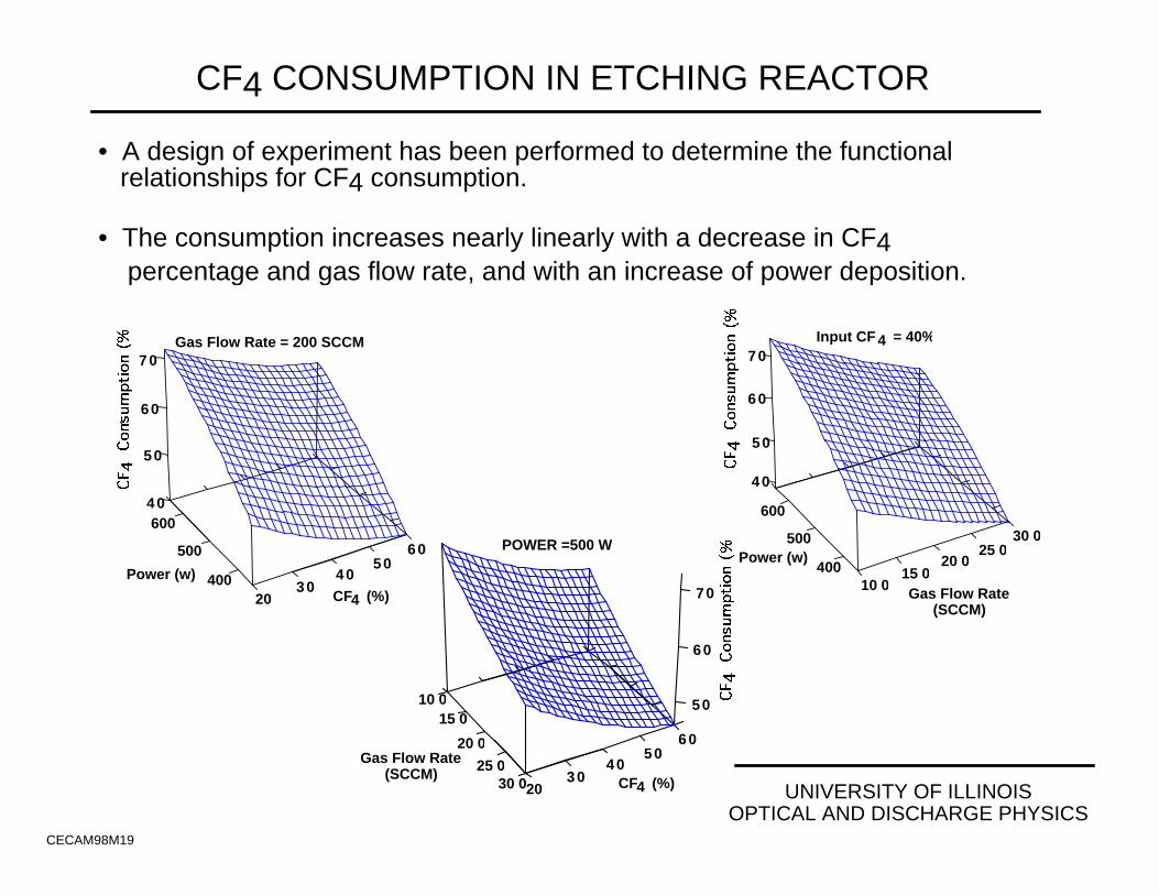
CF4 CONSUMPTION IN ETCHING REACTOR
CECAM98M19
Power (w)
Gas Flow Rate(SCCM)
600
500
400
50
40
60
70
10 015 0
20 025 0
30 0
Input CF 4 = 40%
CF4 (%)2030
4050
60Gas Flow Rate
(SCCM)
10 015 0
20 0
25 030 0
50
60
70
POWER =500 W
Power (w)
600
500
400CF4 (%)20
3040
5060
Gas Flow Rate = 200 SCCM
50
40
60
70
• A design of experiment has been performed to determine the functional relationships for CF4 consumption.
• The consumption increases nearly linearly with a decrease in CF4 percentage and gas flow rate, and with an increase of power deposition.
UNIVERSITY OF ILLINOISOPTICAL AND DISCHARGE PHYSICS
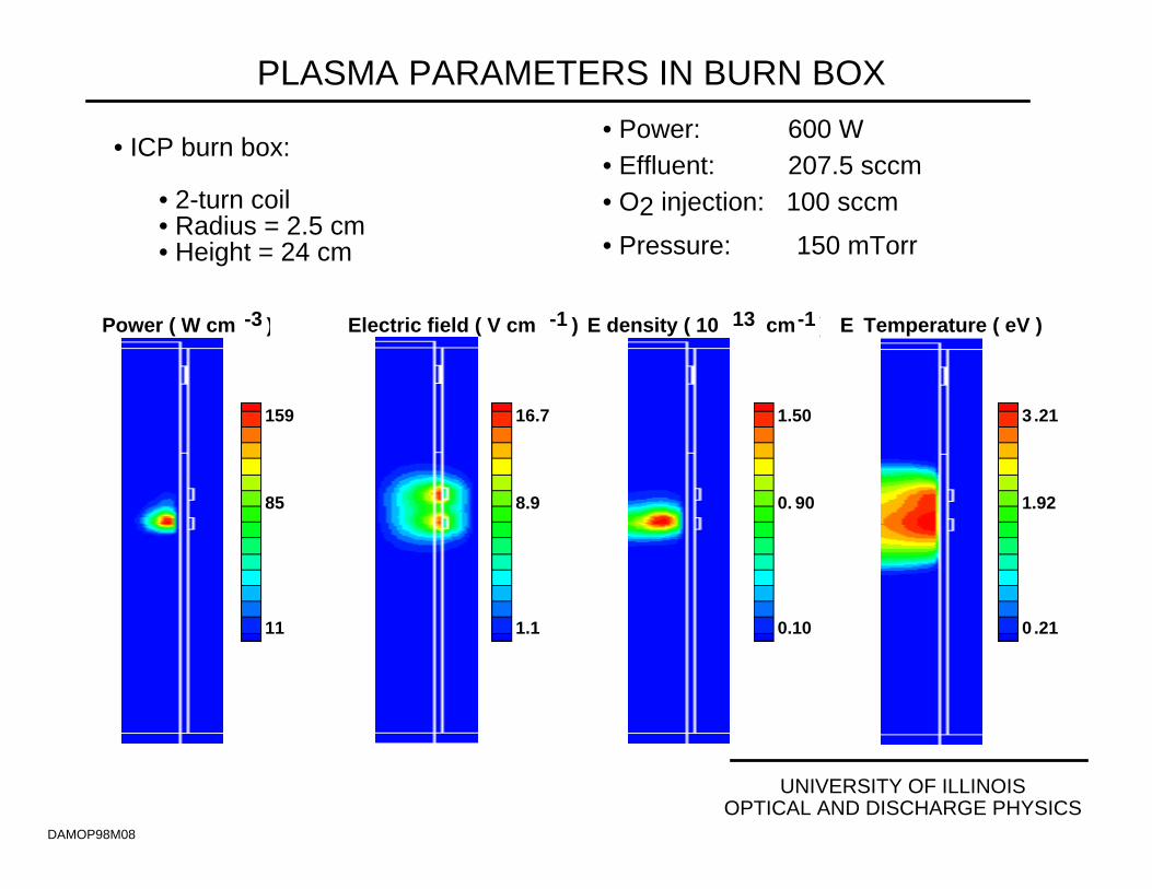
PLASMA PARAMETERS IN BURN BOX
DAMOP98M08
• ICP burn box:
• 2-turn coil• Radius = 2.5 cm• Height = 24 cm
• Power: 600 W • Effluent: 207.5 sccm• O2 injection: 100 sccm
• Pressure: 150 mTorr
159
85
11
Power ( W cm -3 ) Electric field ( V cm -1 )
16.7
8.9
1.1
1.50
0. 90
0.10
E density ( 10 13 cm-1 ) E Temperature ( eV )
3 .21
1.92
0 .21

UNIVERSITY OF ILLINOISOPTICAL AND DISCHARGE PHYSICS
OXYGEN RADICAL PRODUCTION IN BURN BOX
DAMOP98M09
• Electron impact dissociation of O2 and excitation of O generates O, O(1D) and
O+ which oxidize the PFCs and CFx radicals in the plasma chamber effluent.
1 .61
0 .86
0.11
O2 (10 15 cm-3
6 .77
3 .61
0 .45
O (10 14 cm-3 ) O(1D) (10 14 cm-3
2 .34
1.41
0.15
2 .37
1.27
0.15
O+ (10 12 cm-3
UNIVERSITY OF ILLINOISOPTICAL AND DISCHARGE PHYSICS
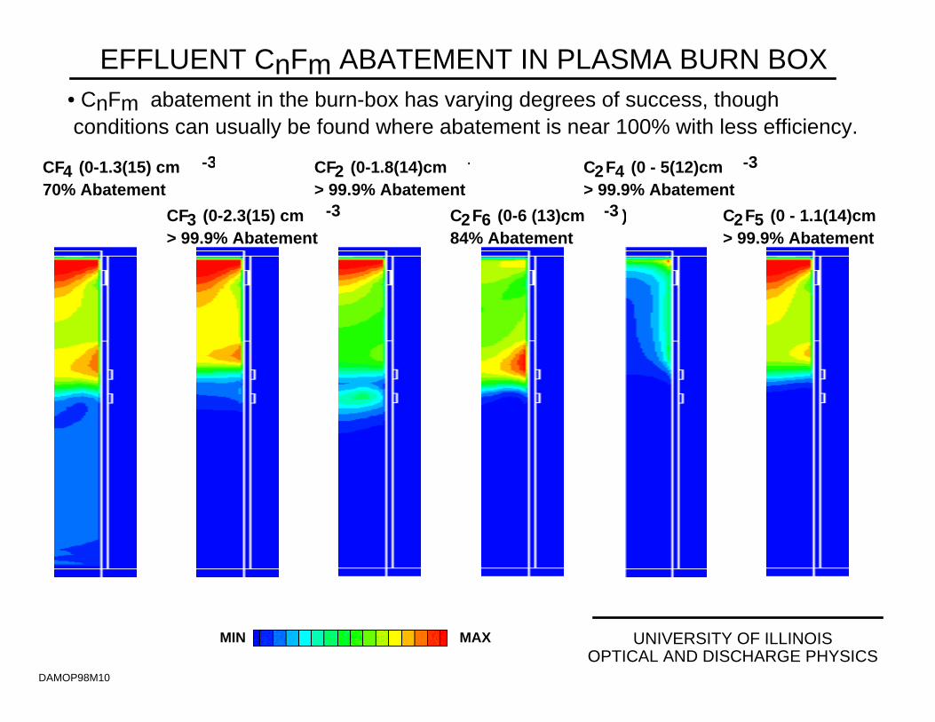
EFFLUENT CnFm ABATEMENT IN PLASMA BURN BOX
DAMOP98M10
• CnFm abatement in the burn-box has varying degrees of success, though conditions can usually be found where abatement is near 100% with less efficiency.
CF4 (0-1.3(15) cm -3
70% Abatement
CF3 (0-2.3(15) cm -3 )> 99.9% Abatement
CF2 (0-1.8(14)cm -3
> 99.9% Abatement
C2F6 (0-6 (13)cm -3 )84% Abatement
C2F4 (0 - 5(12)cm -3
> 99.9% Abatement
C2F5 (0 - 1.1(14)cm> 99.9% Abatement
MIN MAX
UNIVERSITY OF ILLINOISOPTICAL AND DISCHARGE PHYSICS
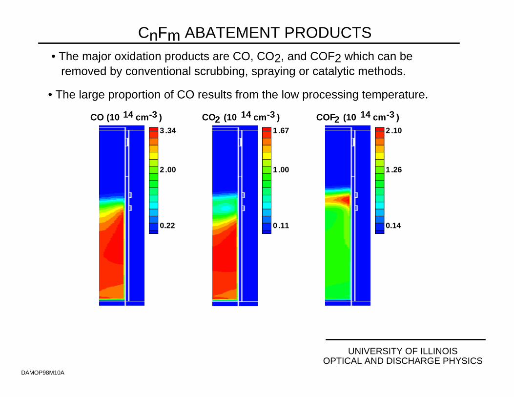
CnFm ABATEMENT PRODUCTS
DAMOP98M10A
• The major oxidation products are CO, CO2, and COF2 which can be removed by conventional scrubbing, spraying or catalytic methods.
• The large proportion of CO results from the low processing temperature.
CO (10 14 cm-3 ) CO2 (10 14 cm-3 ) COF2 (10 14 cm-3 ) 3 .34
2 .00
0.22
1 .67
1 .00
0 .11
2 .10
1 .26
0.14
60
65
70
75
80
85
400 500 600
UNIVERSITY OF ILLINOISOPTICAL AND DISCHARGE PHYSICS
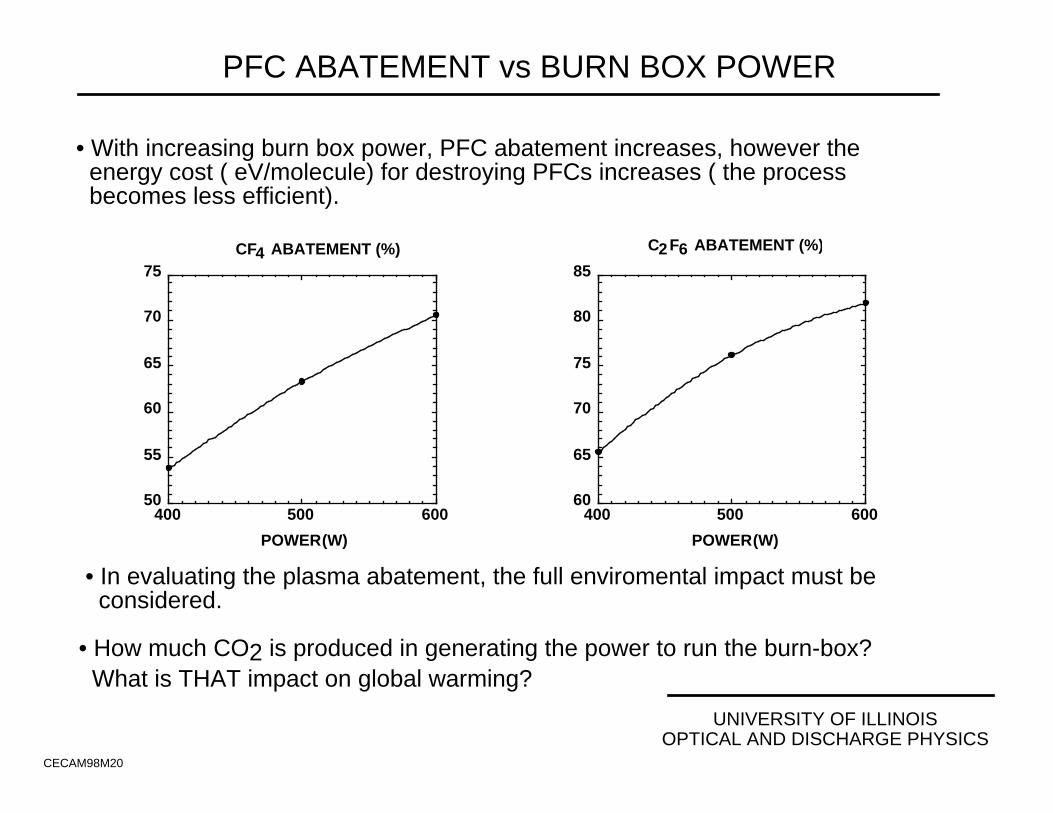
PFC ABATEMENT vs BURN BOX POWER
CECAM98M20
• With increasing burn box power, PFC abatement increases, however the energy cost ( eV/molecule) for destroying PFCs increases ( the process becomes less efficient).
CF4 ABATEMENT (%) C2F6 ABATEMENT (%)
50
55
60
65
70
75
400 500 600
POWER (W) POWER (W)
• In evaluating the plasma abatement, the full enviromental impact must be considered.
• How much CO2 is produced in generating the power to run the burn-box? What is THAT impact on global warming?
CURRENT STATUS OF PLASMA MODELING AND SIMULATIONFOR MATERIALS PROCESSING_______________________________________________
__________________University of Illinois
Optical and Discharge PhysicsDAMP9803
•• Plasma equipment modeling is beginning to mature.
•• Basic physics is moderately well understood•• Equations are moderately well solved•• "Natural" advances in computing (algorithms and speed) will enable
"better" 2-d and 3-d simulations
•• Large gaps in the knowledge base, however, inhibit our ability to addressindustrially relevant problems. THIS IS CURRENTLY THE RATE LIMITINGSTEP!!
•• Lack of cross sections and rate coefficients for chemistries of interest(e.g., C4F8/N2O)
•• Lack of reactive sticking coefficients on surfaces (e.g., Cl(g) + Si(s) →→SiCln(g) )
WHAT DATA ARE REQUIRED?_______________________________________________
__________________University of Illinois
Optical and Discharge PhysicsDAMP9806
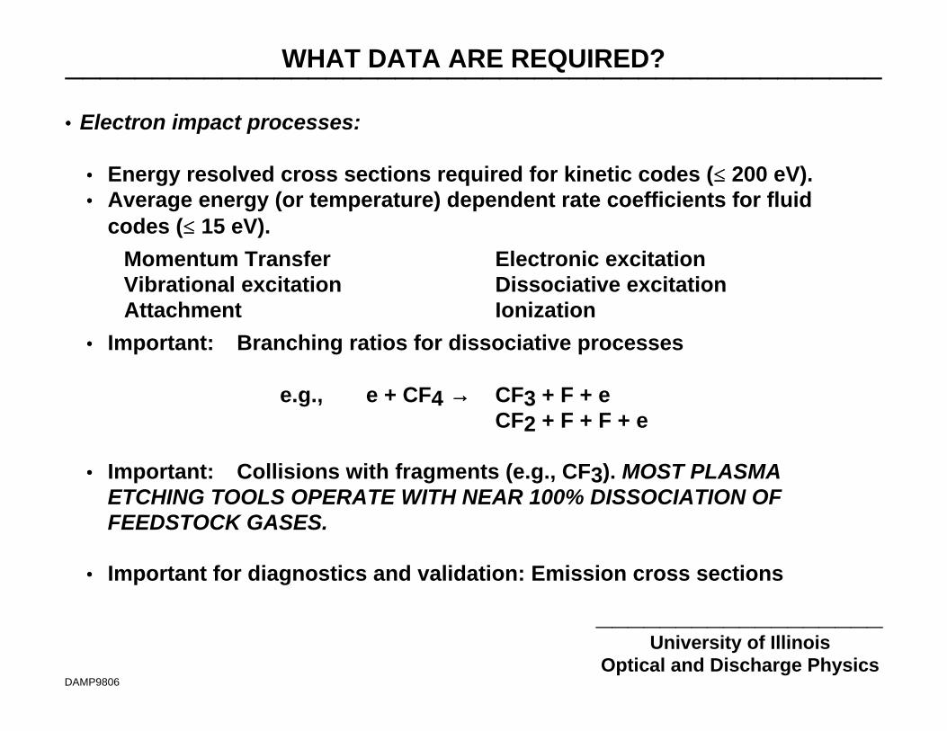
•• Electron impact processes:
•• Energy resolved cross sections required for kinetic codes (≤≤ 200 eV).•• Average energy (or temperature) dependent rate coefficients for fluid
codes (≤≤ 15 eV).
Momentum Transfer Electronic excitationVibrational excitation Dissociative excitationAttachment Ionization
•• Important: Branching ratios for dissociative processes
e.g., e + CF4 →→ CF3 + F + eCF2 + F + F + e
•• Important: Collisions with fragments (e.g., CF3). MOST PLASMAETCHING TOOLS OPERATE WITH NEAR 100% DISSOCIATION OFFEEDSTOCK GASES.
•• Important for diagnostics and validation: Emission cross sections
WHAT DATA ARE REQUIRED?_______________________________________________
__________________University of Illinois
Optical and Discharge PhysicsDAMP9806
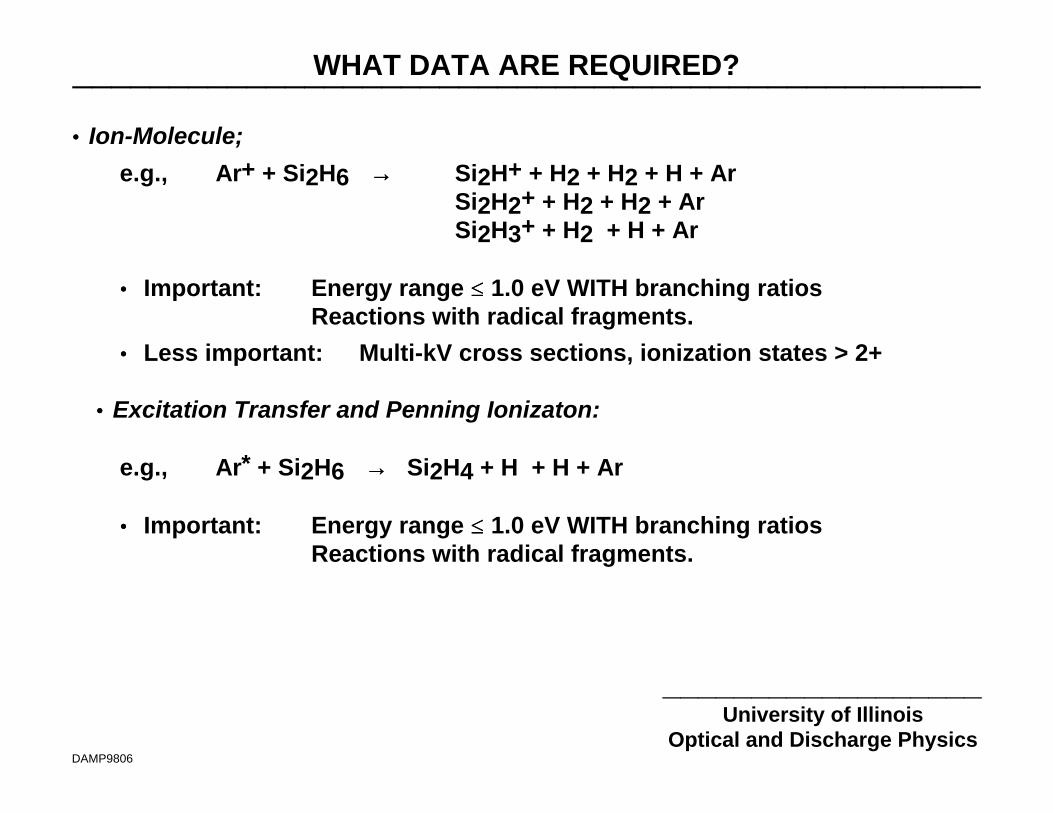
•• Ion-Molecule;
e.g., Ar+ + Si2H6 →→ Si2H+ + H2 + H2 + H + ArSi2H2+ + H2 + H2 + ArSi2H3+ + H2 + H + Ar
•• Important: Energy range ≤≤ 1.0 eV WITH branching ratiosReactions with radical fragments.
•• Less important: Multi-kV cross sections, ionization states > 2+
•• Excitation Transfer and Penning Ionizaton:
e.g., Ar* + Si2H6 →→ Si2H4 + H + H + Ar
•• Important: Energy range ≤≤ 1.0 eV WITH branching ratiosReactions with radical fragments.
WHAT DATA ARE REQUIRED?_______________________________________________
__________________University of Illinois
Optical and Discharge PhysicsDAMP9806
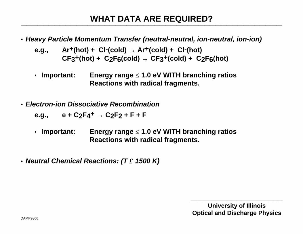
•• Heavy Particle Momentum Transfer (neutral-neutral, ion-neutral, ion-ion)
e.g., Ar+(hot) + Cl-(cold) →→ Ar+(cold) + Cl-(hot)CF3+(hot) + C2F6(cold) →→ CF3+(cold) + C2F6(hot)
•• Important: Energy range ≤≤ 1.0 eV WITH branching ratiosReactions with radical fragments.
•• Electron-ion Dissociative Recombination
e.g., e + C2F4+ →→ C2F2 + F + F
•• Important: Energy range ≤≤ 1.0 eV WITH branching ratiosReactions with radical fragments.
•• Neutral Chemical Reactions: (T ≤≤ 1500 K)
TETRAFLUORMETHANE (CF4)_______________________________________________
__________________University of Illinois
Optical and Discharge PhysicsIOP9708
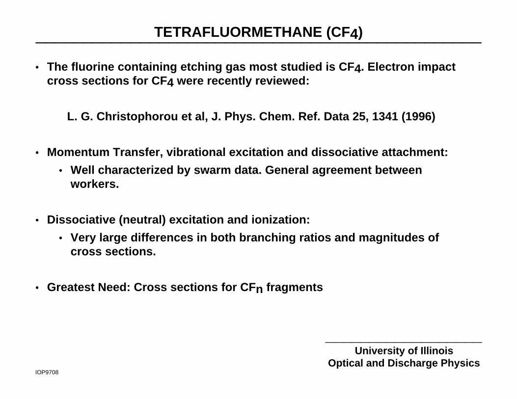
•• The fluorine containing etching gas most studied is CF4. Electron impactcross sections for CF4 were recently reviewed:
L. G. Christophorou et al, J. Phys. Chem. Ref. Data 25, 1341 (1996)
•• Momentum Transfer, vibrational excitation and dissociative attachment:
•• Well characterized by swarm data. General agreement betweenworkers.
•• Dissociative (neutral) excitation and ionization:
•• Very large differences in both branching ratios and magnitudes ofcross sections.
•• Greatest Need: Cross sections for CFn fragments

TETRAFLUORMETHANE (CF4): MOMENTUM TRANSFER_______________________________________________
_____________________________University of Illinois-Optical and Discharge Physics
IOP97011
•• The majority of momentum transfer cross sections are derived from swarmdata. Agreement between investigators is generally good.
L. Christophorou, J. Phys. Chem. Ref. Data 25, 1341, 1996
TETRAFLUORMETHANE (CF4): VIBRATIONAL EXCITATION_______________________________________________________
_____________________________University of Illinois-Optical and Discharge Physics
IOP97012
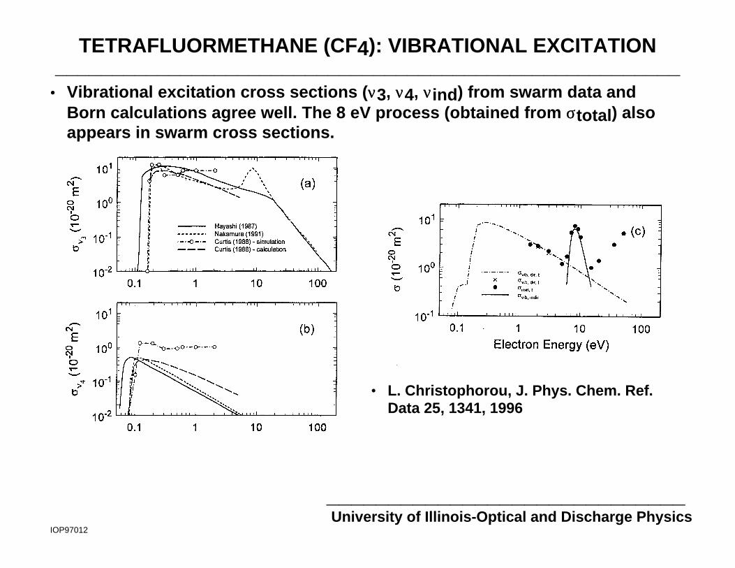
•• Vibrational excitation cross sections (νν3, νν4, ννind) from swarm data andBorn calculations agree well. The 8 eV process (obtained from σσtotal) alsoappears in swarm cross sections.
• L. Christophorou, J. Phys. Chem. Ref.Data 25, 1341, 1996
TETRAFLUORMETHANE (CF4): DISSOCIATIVE IONIZATION_______________________________________________________
_____________________________University of Illinois-Optical and Discharge Physics
IOP97014
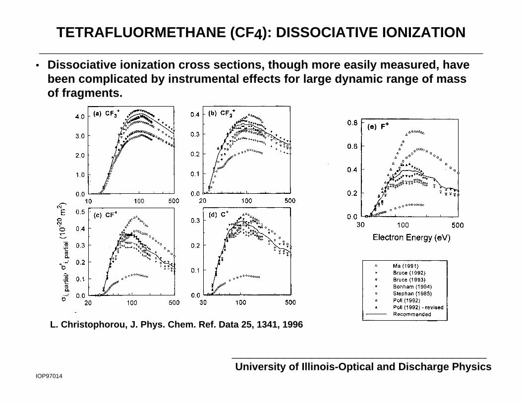
•• Dissociative ionization cross sections, though more easily measured, havebeen complicated by instrumental effects for large dynamic range of massof fragments.
L. Christophorou, J. Phys. Chem. Ref. Data 25, 1341, 1996

TETRAFLUORMETHANE (CF4): DISSOCIATION_______________________________________________________
_____________________________University of Illinois-Optical and Discharge Physics
IOP97013
•• The most critical cross sections for process simulation are for dissociation(dissociative ionization) since these processes generate the radicals.
• Both the magnitude andbranching ratios are required.
e + CF4 →→CFn + mF(2) + e
e + CF4 →→ CFn+ + F(-) + 2e
• These are, unfortunately, themost uncertain andcontroversial.
• Measurements of neutraldissociation cross sections bydouble-cross-beamtechniques differ by an orderof magnitude.
• L. Christophorou, J. Phys. Chem. Ref. Data25, 1341, 1996
TETRAFLUORMETHANE (CF4): "BEAM" vs SWARM____________________________________________________________________
_____________________________University of Illinois-Optical and Discharge Physics
IOP9710
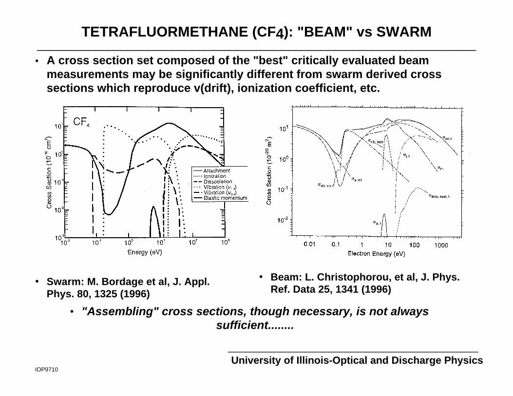
•• A cross section set composed of the "best" critically evaluated beammeasurements may be significantly different from swarm derived crosssections which reproduce v(drift), ionization coefficient, etc.
• Swarm: M. Bordage et al, J. Appl.Phys. 80, 1325 (1996)
• Beam: L. Christophorou, et al, J. Phys.Ref. Data 25, 1341 (1996)
• "Assembling" cross sections, though necessary, is not alwayssufficient........
TETRAFLUORMETHANE (CF4): MEASURE OF GOODNESS_______________________________________________
_____________________________University of Illinois-Optical and Discharge Physics
IOP9709
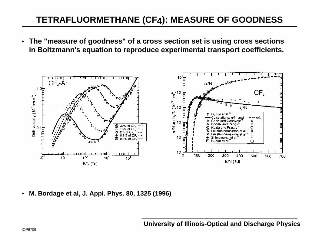
•• The "measure of goodness" of a cross section set is using cross sectionsin Boltzmann's equation to reproduce experimental transport coefficients.
• M. Bordage et al, J. Appl. Phys. 80, 1325 (1996)
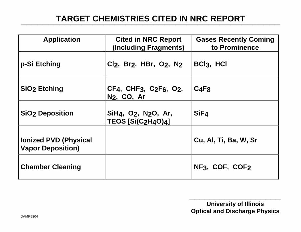
TARGET CHEMISTRIES CITED IN NRC REPORT_______________________________________________
__________________University of Illinois
Optical and Discharge PhysicsDAMP9804
Application Cited in NRC Report(Including Fragments)
Gases Recently Comingto Prominence
p-Si Etching Cl2, Br2, HBr, O2, N2 BCl3, HCl
SiO2 Etching CF4, CHF3, C2F6, O2,N2, CO, Ar
C4F8
SiO2 Deposition SiH4, O2, N2O, Ar,TEOS [Si(C2H4O)4]
SiF4
Ionized PVD (PhysicalVapor Deposition)
Cu, Al, Ti, Ba, W, Sr
Chamber Cleaning NF3, COF, COF2
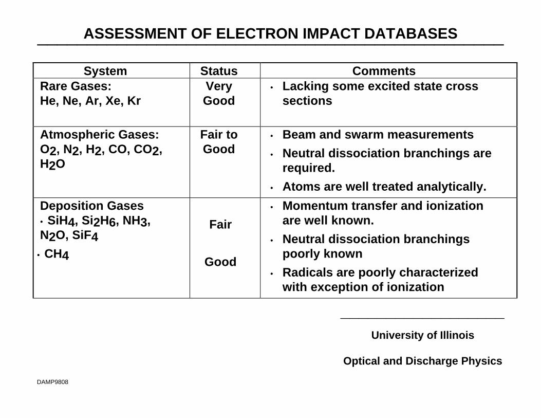
ASSESSMENT OF ELECTRON IMPACT DATABASES_______________________________________________
__________________University of Illinois
Optical and Discharge Physics
DAMP9808
System Status CommentsRare Gases:He, Ne, Ar, Xe, Kr
VeryGood
•• Lacking some excited state crosssections
Atmospheric Gases:O2, N2, H2, CO, CO2,H2O
Fair toGood
•• Beam and swarm measurements
•• Neutral dissociation branchings arerequired.
•• Atoms are well treated analytically.
Deposition Gases•• SiH4, Si2H6, NH3,N2O, SiF4
•• CH4
Fair
Good
•• Momentum transfer and ionizationare well known.
•• Neutral dissociation branchingspoorly known
•• Radicals are poorly characterizedwith exception of ionization

ASSESSMENT OF ELECTRON IMPACT DATABASES_______________________________________________
__________________University of Illinois
Optical and Discharge Physics
DAMP9808
•• TEOS, DMSO Poor •• Only isolated data available•• Momentum transfer fair•• Dissociative ionization branchingsare known.
•• Etch Gases:•• CF4, C2F6
•• CCl4, Cl2, HCl
Fair •• Momentum transfer, vib swarmderived.
•• Dissociative ionization characterizedthough with disagreements
•• Neutral dissociation branchingsavailable but with large variance
•• Cl, F have theoretical data
•• Radical data is largely missing.
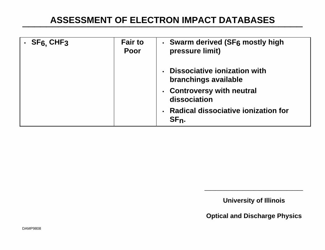
ASSESSMENT OF ELECTRON IMPACT DATABASES_______________________________________________
__________________University of Illinois
Optical and Discharge Physics
DAMP9808
•• SF6, CHF3 Fair toPoor
•• Swarm derived (SF6 mostly highpressure limit)
•• Dissociative ionization withbranchings available
•• Controversy with neutraldissociation
•• Radical dissociative ionization forSFn.
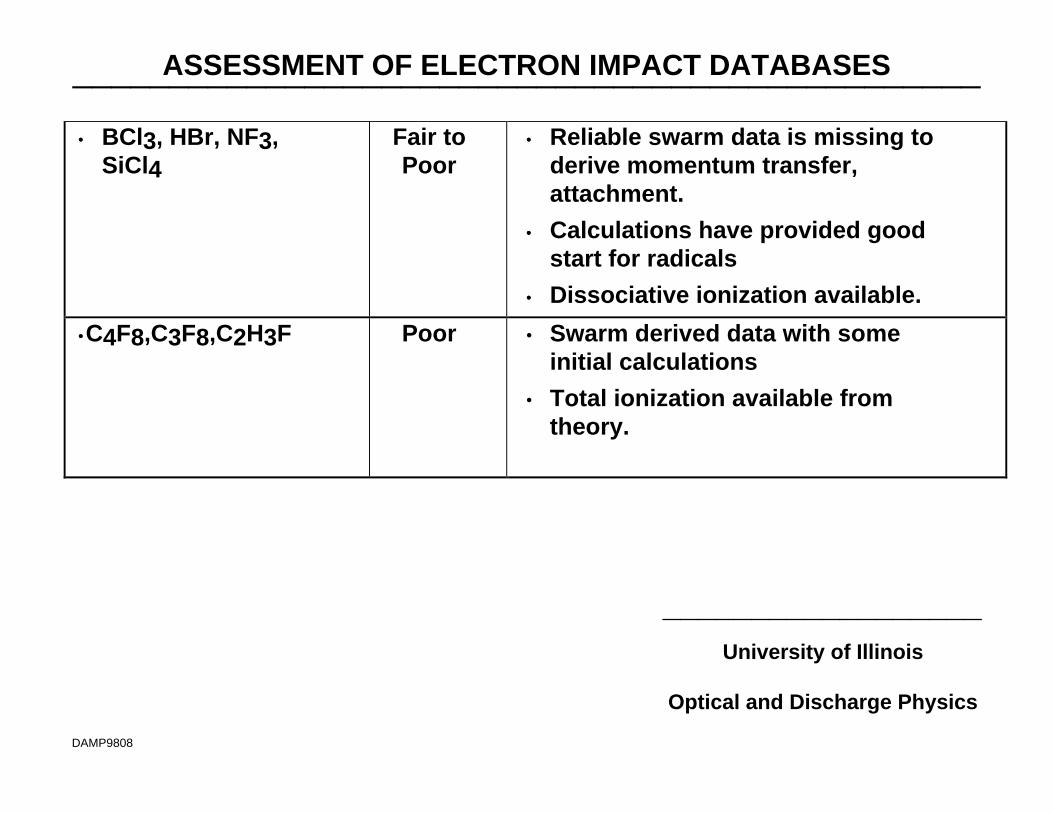
ASSESSMENT OF ELECTRON IMPACT DATABASES_______________________________________________
__________________University of Illinois
Optical and Discharge Physics
DAMP9808
•• BCl3, HBr, NF3,SiCl4
Fair toPoor
•• Reliable swarm data is missing toderive momentum transfer,attachment.
•• Calculations have provided goodstart for radicals
•• Dissociative ionization available.
••C4F8,C3F8,C2H3F Poor • Swarm derived data with someinitial calculations
• Total ionization available fromtheory.

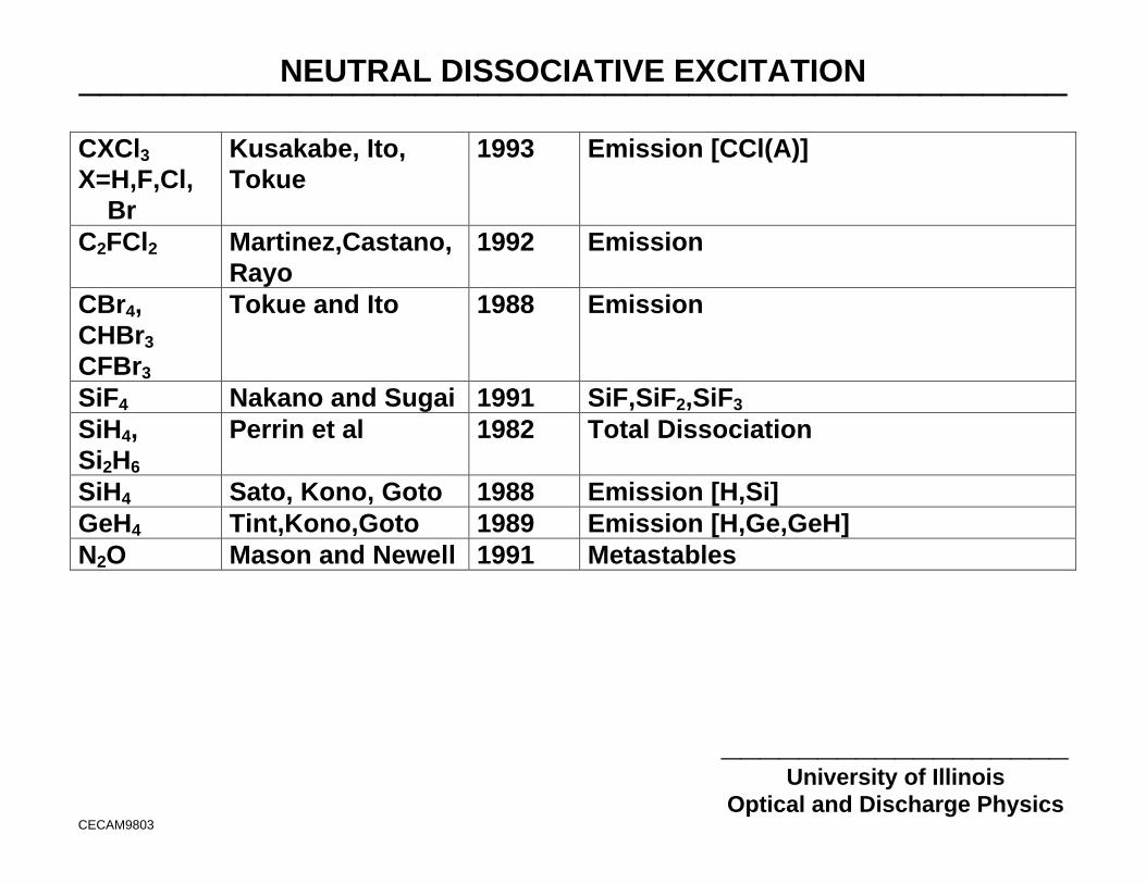
NEUTRAL DISSOCIATIVE EXCITATION_______________________________________________
__________________University of Illinois
Optical and Discharge PhysicsCECAM9803
• The majority of experimental cross sections for electron impactdissociative excitation for for excited products.
• Cross beam measurements of producing partial cross sections for neutralcross sections are available for a small subset of process gases.
Molecule Authors/Group Year Cross SectionsBCl3 Gilbert,Siegel,
Becker1990 Emission [B,BCl(A)]
BCl3 Toku, et al 1992 Emission [B,BCl(A)]CF4,CF3H,C2F6,C3F8
Winters 1982 Total dissociation
C4F8 Toyoda, Iio, Sugai 1997 CF,CF2,C3F5, and ionsCF4,CHF3 McConkey 1989 Metastable productsCF4 Bonham 1992 CF3,CF2
CF4 Nakano and Sugai 1992 CF,CF2,CF3
NF3,CF4,SF6
Blanks,Tabor,Becker
1983 Emission [F(3p-3s)]
NEUTRAL DISSOCIATIVE EXCITATION_______________________________________________
__________________University of Illinois
Optical and Discharge PhysicsCECAM9803
CXCl3X=H,F,Cl, Br
Kusakabe, Ito,Tokue
1993 Emission [CCl(A)]
C2FCl2 Martinez,Castano,Rayo
1992 Emission
CBr4,CHBr3
CFBr3
Tokue and Ito 1988 Emission
SiF4 Nakano and Sugai 1991 SiF,SiF2,SiF3
SiH4,Si2H6
Perrin et al 1982 Total Dissociation
SiH4 Sato, Kono, Goto 1988 Emission [H,Si]GeH4 Tint,Kono,Goto 1989 Emission [H,Ge,GeH]N2O Mason and Newell 1991 Metastables
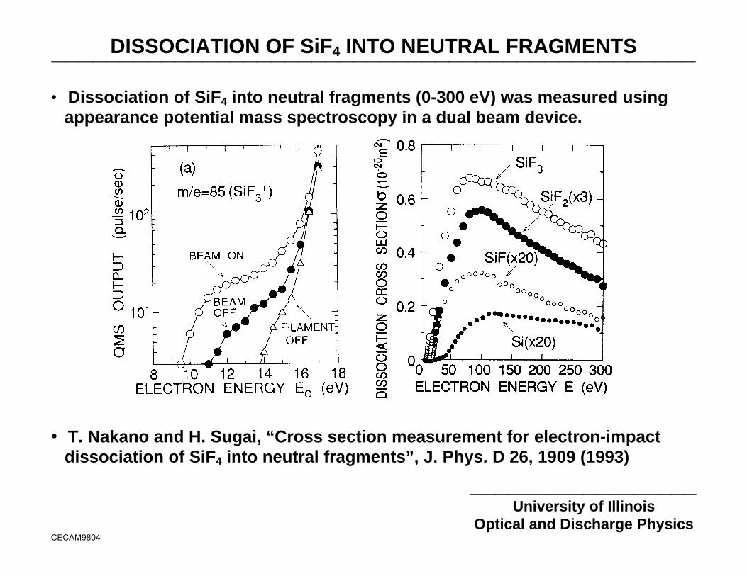
DISSOCIATION OF SiF4 INTO NEUTRAL FRAGMENTS_______________________________________________
__________________University of Illinois
Optical and Discharge PhysicsCECAM9804
• Dissociation of SiF4 into neutral fragments (0-300 eV) was measured usingappearance potential mass spectroscopy in a dual beam device.
• T. Nakano and H. Sugai, “Cross section measurement for electron-impactdissociation of SiF4 into neutral fragments”, J. Phys. D 26, 1909 (1993)
DATABASE NEEDS FOR RARE GAS-METAL CHEMISTRIES_______________________________________________
__________________University of Illinois
Optical and Discharge PhysicsCECAM9807
• Newly developed techniques for ionized metal physical vapor deposition(IMPVD) are being used for for interconnect wiring, barrier coatings andhigh permittivy dielectrics.
• These applications have increased needs for electron impact and rare gasexcitation transfer data for metal atoms.
• Metals of interest: Cu, Al, W, Ti, Ba, Sr
• The prevalance of low lying metastable states of the metals emphasizesthe need for electron impact cross sections for excited states. (Recall, inCu IMPVD tools, the flux of Cu(2D) to the substrate can exceed that ofCu(2S).)
• Due to the low mole fractions of the metals in rare gas buffers, reliableinelastic cross sections are more important than elastic, thoughdevelopment of self-sputtering systems may change this assertion.
• Penning ionization and rare gas charge exchange are dominant sources ofionization, and so those rate coefficients are also required.
UNIVERSITY OF ILLINOISOPTICAL AND DISCHARGE PHYSICS
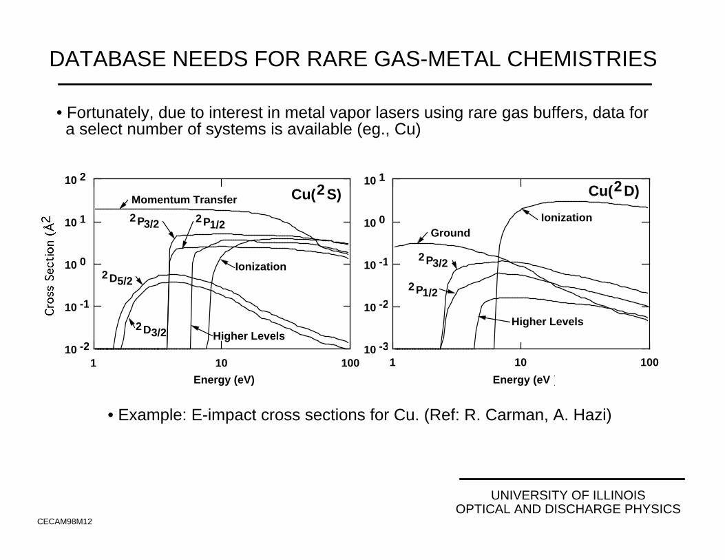
DATABASE NEEDS FOR RARE GAS-METAL CHEMISTRIES
CECAM98M12
• Fortunately, due to interest in metal vapor lasers using rare gas buffers, data for a select number of systems is available (eg., Cu)
• Example: E-impact cross sections for Cu. (Ref: R. Carman, A. Hazi)
1 10 100
10 2
10 -2
10 -1
10 0
10 1
Energy (eV)
Momentum Transfer
Ionization
Higher Levels
2P3/2 2P1/2
2D5/2
2D3/2
Cu(2S)
Energy (eV )
10 -3
10 -2
10 -1
10 0
10 1
1 10 100
Ground
2P3/2
2P1/2
Ionization
Higher Levels
Cu(2D)
HOW GOOD DOES THE DATA NEED TO BE?What is your application?_______________________________________________
__________________University of Illinois
Optical and Discharge PhysicsCECAM9808
• The goodness of database varies by the application, and is often a case ofscience vs. technology.
• Screening:
• There is a tremendous need for electron impact cross section datasetswhich can be generated quickly, though are not necessarily “99.99%accurate”.
• The application is performing zeroth order evaluations or screening ofnew processes or equipment.
• The absolute accuracy of the screening is not as important as isconsistent case-to-case systematic trends.
HOW GOOD DOES THE DATA NEED TO BE?What is your application?_______________________________________________
__________________University of Illinois
Optical and Discharge PhysicsCECAM9808
• Equipment Design:
• The details of how a chamber is designed (with respect to uniformity offluxes, parasitic capacitance) do not critically depend on the details ofthe chemistry.
• Since a given tool will be used with many chemistries during itslifetime, “tuning” a tool for the quirks of a specific chemistry is notadvisable.
• Well characterized datasets for “classes” of chemistries are required tocover the parameter space of anticipated applications.
• Non- or moderately attaching (e.g., Ar/N2/O2)
• Highly attaching (e.g., Cl2)
• Rapidly dissociated (e.g., SF6)
HOW GOOD DOES THE DATA NEED TO BE?What is your application?_______________________________________________
__________________University of Illinois
Optical and Discharge PhysicsCECAM9808
• Model Validation:
• Similar to equipment design, well characterized datasets for “classes”of chemistries are required to cover the parameter space of anticipatedapplications.
• Since the “faith” in the models will be largely based on these validationexercises, it is important that ambiguities and caveats in thesedatasets be well advertised and understood by their users.
• Process Design:
• The most critical requirements for accuracy of the data are in processdesign where specifics of the reactant fluxes (magnitudes and molefractions) have large impacts on the final product.
UNIVERSITY OF ILLINOISOPTICAL AND DISCHARGE PHYSICS
HOW ACCURATE DOES THE DATA NEED TO BE?
CECAM98M13
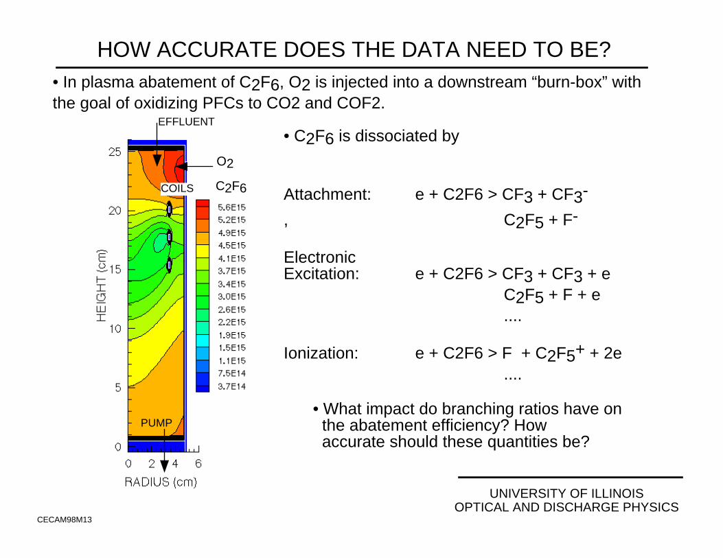
• In plasma abatement of C2F6, O2 is injected into a downstream “burn-box” with the goal of oxidizing PFCs to CO2 and COF2.
• What impact do branching ratios have on the abatement efficiency? How accurate should these quantities be?
EFFLUENT
PUMP
COILS C2F6
• C2F6 is dissociated by
Attachment: e + C2F6 > CF3 + CF3-
, C2F5 + F-
ElectronicExcitation: e + C2F6 > CF3 + CF3 + e
C2F5 + F + e ....
Ionization: e + C2F6 > F + C2F5+ + 2e ....
O2
UNIVERSITY OF ILLINOISOPTICAL AND DISCHARGE PHYSICS
BRANCHING RATIO FOR C2F6 DISSOCIATIVE ATTACHMENT
CECAM98M14
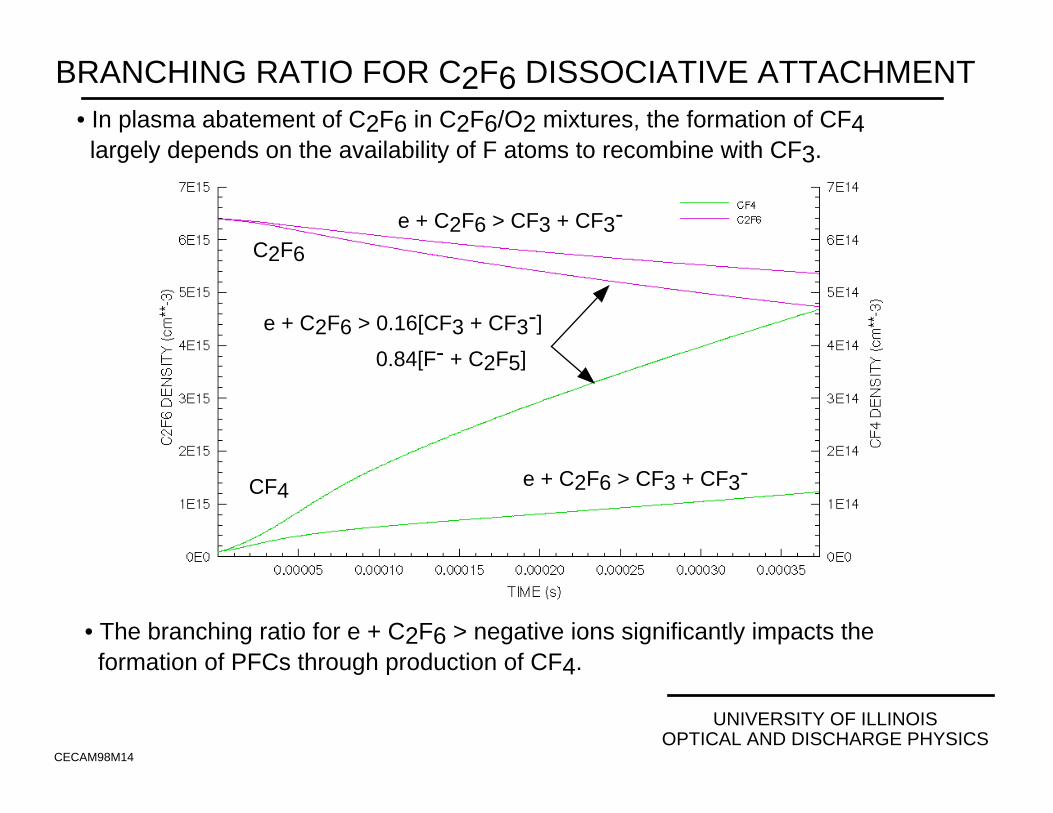
• In plasma abatement of C2F6 in C2F6/O2 mixtures, the formation of CF4 largely depends on the availability of F atoms to recombine with CF3.
• The branching ratio for e + C2F6 > negative ions significantly impacts the formation of PFCs through production of CF4.
e + C2F6 > CF3 + CF3-
C2F6
CF4 e + C2F6 > CF3 + CF3-
e + C2F6 > 0.16[CF3 + CF3-]
0.84[F- + C2F5]

IMPORTANCE OF RAPIDLY GENERATING “APPROXIMATE”DATASETS_______________________________________________
__________________University of Illinois
Optical and Discharge PhysicsCECAM9811
• There are obvious tradeoffs between the length of time required togenerate a dataset, and its accuracy or reliability.
• There are many “screening” applications where “completeness” andconsistency between rapidly generated datasets is more important thantheir accuracy.
• (Semi-)Analytic, rapid numerical or analogous experimental methods forgenerating electron impact cross sections must be relied on to provided tomeet the majority of these needs.
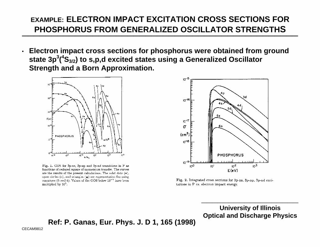
EXAMPLE: ELECTRON IMPACT EXCITATION CROSS SECTIONS FORPHOSPHORUS FROM GENERALIZED OSCILLATOR STRENGTHS_______________________________________________
__________________University of Illinois
Optical and Discharge Physics
CECAM9812
Ref: P. Ganas, Eur. Phys. J. D 1, 165 (1998)
• Electron impact cross sections for phosphorus were obtained from groundstate 3p3(4S3/2) to s,p,d excited states using a Generalized OscillatorStrength and a Born Approximation.
SEMIANALYTIC IONIZATION CROSS SECTIONS FOR MOLECULES_______________________________________________
__________________University of Illinois
Optical and Discharge PhysicsCECAM9806
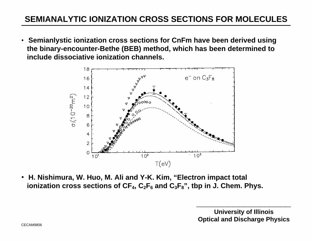
• Semianlystic ionization cross sections for CnFm have been derived usingthe binary-encounter-Bethe (BEB) method, which has been determined toinclude dissociative ionization channels.
• H. Nishimura, W. Huo, M. Ali and Y-K. Kim, “Electron impact totalionization cross sections of CF4, C2F6 and C3F8”, tbp in J. Chem. Phys.
AB INITIO CALCULATIONS OF E-IMPACT X-SECTIONS: V. McKoy_______________________________________________
______________________________University of Illinois- Optical and Discharge Physics
DAMP9807
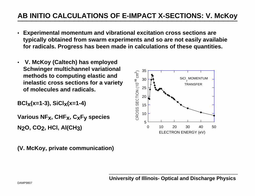
•• Experimental momentum and vibrational excitation cross sections aretypically obtained from swarm experiments and so are not easily availabiefor radicals. Progress has been made in calculations of these quantities.
•• V. McKoy (Caltech) has employedSchwinger multichannel variationalmethods to computing elastic andinelastic cross sections for a varietyof molecules and radicals.
BClx(x=1-3), SiClx(x=1-4)
Various NFx, CHFx, CxFy species
N2O, CO2, HCl, Al(CH3)
(V. McKoy, private communication)
5
10
15
20
25
30
35
0 10 20 30 40 50ELECTRON ENERGY (eV)
SiCl2 MOMENTUM
TRANSFER
SWARM DERIVED SiF4 CROSS SECTION SET_______________________________________________
__________________University of Illinois
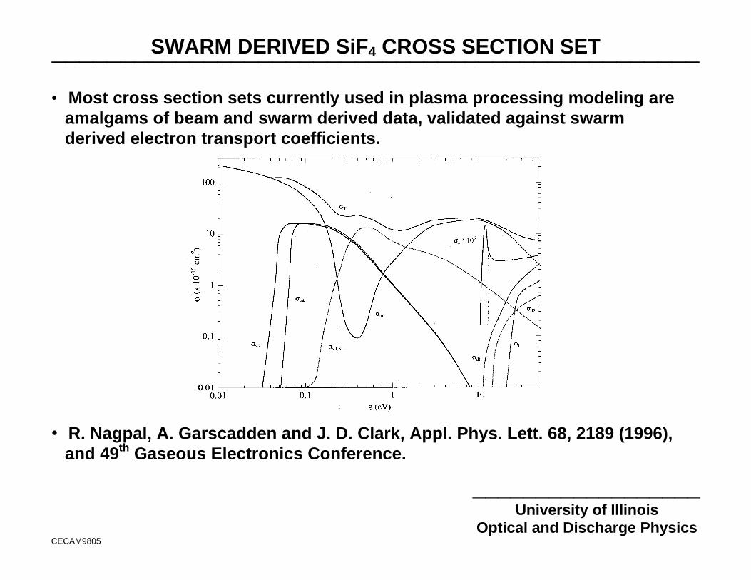
Optical and Discharge PhysicsCECAM9805
• Most cross section sets currently used in plasma processing modeling areamalgams of beam and swarm derived data, validated against swarmderived electron transport coefficients.
• R. Nagpal, A. Garscadden and J. D. Clark, Appl. Phys. Lett. 68, 2189 (1996),and 49th Gaseous Electronics Conference.
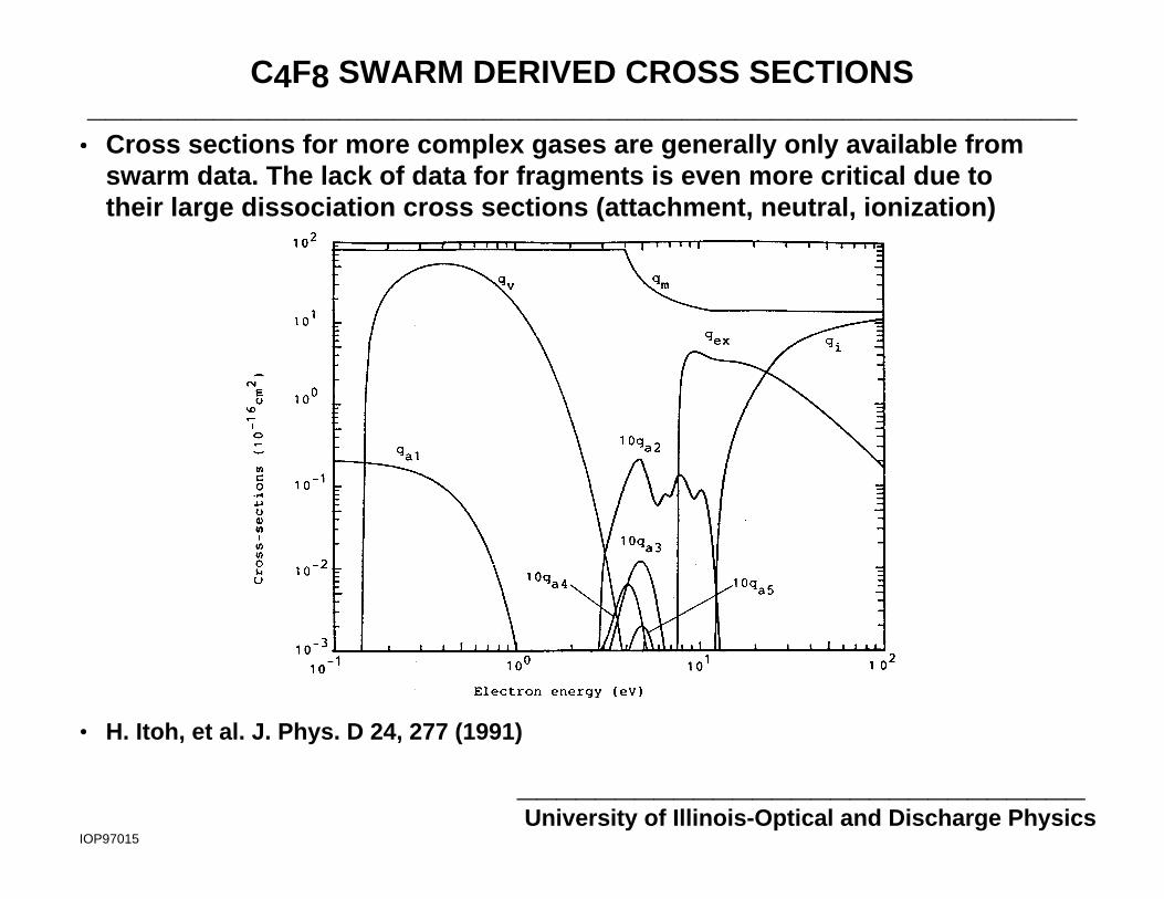
C4F8 SWARM DERIVED CROSS SECTIONS_______________________________________________________
_____________________________University of Illinois-Optical and Discharge Physics
IOP97015
•• Cross sections for more complex gases are generally only available fromswarm data. The lack of data for fragments is even more critical due totheir large dissociation cross sections (attachment, neutral, ionization)
• H. Itoh, et al. J. Phys. D 24, 277 (1991)
PRESENT CAPABILITY AND FUTURE DEVELOPMENT_______________________________________________
__________________University of Illinois
Optical and Discharge PhysicsCECAM9821
••Virtual prototyping of new equipment designs and optimization of currentdesigns are, with realistic expectations, accessible today.
•• General acceptance of this ability will require further improvements inpresently available models.
•• Modular simulations able to address a variety of plasma equipment.
•• Databases and reaction mechanisms which are integrated into the modelor are internet accessble
•• Expert systems which, given equpment parameters provide the user
•• "Good guess" initial conditions•• Optimally chosen algorithms
•• Seamless coupling CAD mesh generators to PEMS; and PEMS to profilesimulators
UNIVERSITY OF ILLINOISOPTICAL AND DISCHARGE PHYSICS
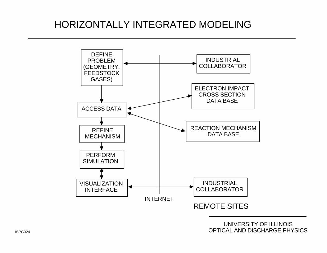
HORIZONTALLY INTEGRATED MODELING
ISPC024
ELECTRON IMPACTCROSS SECTION
DATA BASE
REACTION MECHANISMDATA BASE
INDUSTRIALCOLLABORATOR
REMOTE SITESINTERNET
DEFINEPROBLEM
(GEOMETRY,FEEDSTOCK
GASES)
ACCESS DATA
REFINEMECHANISM
PERFORMSIMULATION
VISUALIZATIONINTERFACE
INDUSTRIALCOLLABORATOR
10 s 20 s 40 s 80 s
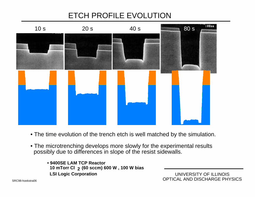
• The time evolution of the trench etch is well matched by the simulation.
• The microtrenching develops more slowly for the experimental results possibly due to differences in slope of the resist sidewalls.
UNIVERSITY OF ILLINOISOPTICAL AND DISCHARGE PHYSICSSRC98-hoekstra06
ETCH PROFILE EVOLUTION
• 9400SE LAM TCP Reactor 10 mTorr Cl 2 (60 sccm) 600 W , 100 W bias LSI Logic Corporation

3-D FINITE TRENCH: SiClx STICKING COEFFICIENT
• LAM TCP 9400SE Reactor, 10 mTorr Cl2 (60 sccm) 100 W RF Bias
123
1 µm
2 µm
1.5 µm
ResistSi
SiO2
1 2 3
• When the redeposition of SiClx (etch product) is low, a narrow angular spread of the IEAD produces “crisp” 3-plane corners.
• As the sticking coefficient increases (due to temperature excursions), the narrow IEAD is not able to remove reposited etch products from side/end walls.
• The result is inward sloping of the side/end walls.
UNIVERSITY OF ILLINOISOPTICAL AND DISCHARGE PHYSICSDAMOPM01
1 µm SiClx
StickingCoefficient
0.1
0.3
Cl+
=SiCl
SiCl2
CONCLUDING REMARKS_______________________________________________
__________________University of Illinois
Optical and Discharge PhysicsCECAM9822
•• Plasma equipment modeling has made great strides over the past 5 yearsin developing an infrastructure for process design.
•• "Natural" advances in computing power, algorithms and validation willcontinued to improve those capabilities.
•• The rate limiting step in application of plasma equipment models isincomplete databases.
•• The database for plasma processing is a bit schizophrenic: For somesystems, the database is very good, for other systems very poor.
•• The "database" is very "distributed" in the literature. Simply compilingwhat is available into a reasonable "reaction mechanism" is a largeundertaking.
CONCLUDING REMARKS_______________________________________________
__________________University of Illinois
Optical and Discharge PhysicsCECAM9822
• Large unknowns in the electron impact database include
• Branching ratios for (neutral) dissociative processes• All parameters for fragment/radical ions
• Methodologies are required to rapidly produce “adequate” cross sectionsets to meet short term “technological” needs. Meeting these needs willform the basis of longer term relationships which will support moreaccurate “science”