
Modeling and Performance Analysis of Fuzzy Logic ... · PDF fileModeling and Performance...
6
ISSN (Online) : 2319 - 8753 ISSN (Print) : 2347 - 6710 International Journal of Innovative Research in Science, Engineering and Technology Volume 3, Special Issue 3, March 2014 2014 International Conference on Innovations in Engineering and Technology (ICIET’14) On 21 st &22 nd March Organized by K.L.N. College of Engineering, Madurai, Tamil Nadu, India Copyright to IJIRSET www.ijirset.com 24 M.R. Thansekhar and N. Balaji (Eds.): ICIET’14 ABSTRACT—This manuscript deals with fuzzy logic controller based Direct Torque Control (DTC) of three phase Induction Motor Drive using MATLAB and its toolbox SIMULINK. The Direct Torque Control of VSI fed Induction Motor is implemented with the help of Hysteresis Band (HB) controllers (one for flux control and other for torque control), a voltage source inverter and a switching table. The major problem that is usually associated with DTC drive is torque ripple. To overcome the problem direct torque control method has been optimized by using fuzzy logic controller. The presented fuzzy based control scheme combines the benefits of fuzzy logic control technique along with direct torque control technique. With aid of the developed model, the steady and transient-state characteristics of current, speed and torque of three phase induction motor can be effectively examined and analyzed. KEYWORDS—Direct torque control, induction motor, Fuzzy logic controller, MATLAB/Simulink I. INTRODUCTION Fuzzy logic is recently used in drive control applications. Recent years, fuzzy logic control has found many applications in industries for drive control. This is so largely increasing because fuzzy logic controller has the capability to control nonlinear systems where no mathematical model is available [1]. AC motors combined with their drives have replaced DC motors in industrial applications due to their lower cost, better reliability, lower weight, and reduced maintenance requirement. Mechanical energy is more than often required at variable speeds, where the speed control system is not a trivial matter. Scalar speed control method has good steady state response but poor dynamic response. To achieve good dynamic response as well as good steady state response, vector control was introduced. But it has complexity in construction and control. In recent years several studies have been carried out for the purpose to find out alternative solution of field oriented control drive to achieve accurate and fast response of flux and torque and also to reduce the complexity of the control system of the drive. To overcome the disadvantages of field oriented control technique, in the middle of 1980’s a new quick response for the torque control of induction motors was proposed by Takahashi as direct torque control (DTC) [7]. DTC provides quick response with simple control structure and hence, this technique is most popularity in industries [7]. Though, DTC has good dynamic performance, it has some drawbacks such as high ripple in torque due to variation in switching frequency of the inverter. DTC was first introduced, with variations to its original structure to overcome the inherent disadvantages in any hysteresis- based controller, such as high torque ripple [8]. To overcome this problem, various techniques have been implemented like variable hysteresis bands [9], space vector modulation techniques [4] and intelligent control methods [13]. This paper proposes Fuzzy logic control of direct torque control (DTC) to improve dynamic response performance and decrease the torque ripples. Fig 1 shows the block diagram of proposed model. Modeling and Performance Analysis of Fuzzy Logic Controller Based Direct Torque Control of VLSI Fed Three Phase Induction Motor S.Prabaharan 1 , P.RameshBabu 2 , N.Vijayasarathi 3 1 P.G. Scholar (M.E. Power Electronics and Drives), Department of Electrical and Electronics Engineering, Saranathan College of Engineering, India 2 Assistant Professor, Department of Electrical and Electronics Engineering, Saranathan College of Engineering, India 3 Assistant Professor, Department of Electrical and Electronics Engineering, Saranathan College of Engineering, India
Transcript of Modeling and Performance Analysis of Fuzzy Logic ... · PDF fileModeling and Performance...
ISSN (Online) : 2319 - 8753 ISSN (Print) : 2347 - 6710
International Journal of Innovative Research in Science, Engineering and Technology
Volume 3, Special Issue 3, March 2014
2014 International Conference on Innovations in Engineering and Technology (ICIET’14)
On 21st&22ndMarch Organized by
K.L.N. College of Engineering, Madurai, Tamil Nadu, India
Copyright to IJIRSET www.ijirset.com 24
M.R. Thansekhar and N. Balaji (Eds.): ICIET’14
ABSTRACT—This manuscript deals with fuzzy logic
controller based Direct Torque Control (DTC) of three
phase Induction Motor Drive using MATLAB and its
toolbox SIMULINK. The Direct Torque Control of VSI
fed Induction Motor is implemented with the help of
Hysteresis Band (HB) controllers (one for flux control
and other for torque control), a voltage source inverter
and a switching table. The major problem that is usually
associated with DTC drive is torque ripple. To overcome
the problem direct torque control method has been
optimized by using fuzzy logic controller. The presented
fuzzy based control scheme combines the benefits of
fuzzy logic control technique along with direct torque
control technique. With aid of the developed model, the
steady and transient-state characteristics of current, speed
and torque of three phase induction motor can be
effectively examined and analyzed.
KEYWORDS—Direct torque control, induction motor,
Fuzzy logic controller, MATLAB/Simulink
I. INTRODUCTION
Fuzzy logic is recently used in drive control
applications. Recent years, fuzzy logic control has found
many applications in industries for drive control. This is
so largely increasing because fuzzy logic controller has
the capability to control nonlinear systems where no
mathematical model is available [1]. AC motors
combined with their drives have replaced DC motors in
industrial
applications due to their lower cost, better reliability,
lower weight, and reduced maintenance requirement.
Mechanical energy is more than often required at variable
speeds, where the speed control system is not a trivial
matter. Scalar speed control method has good steady state
response but poor dynamic response. To achieve good
dynamic response as well as good steady state response,
vector control was introduced. But it has complexity in
construction and control. In recent years several studies have
been carried out for the purpose to find out alternative
solution of field oriented control drive to achieve accurate and
fast response of flux and torque and also to reduce the
complexity of the control system of the drive. To overcome
the disadvantages of field oriented control technique, in
the middle of 1980’s a new quick response for the torque
control of induction motors was proposed by Takahashi
as direct torque control (DTC) [7]. DTC provides quick
response with simple control structure and hence, this
technique is most popularity in industries [7]. Though,
DTC has good dynamic performance, it has some
drawbacks such as high ripple in torque due to variation
in switching frequency of the inverter. DTC was first
introduced, with variations to its original structure to
overcome the inherent disadvantages in any hysteresis-
based controller, such as high torque ripple [8]. To
overcome this problem, various techniques have been
implemented like variable hysteresis bands [9], space
vector modulation techniques [4] and intelligent control
methods [13]. This paper proposes Fuzzy logic control of
direct torque control (DTC) to improve dynamic response
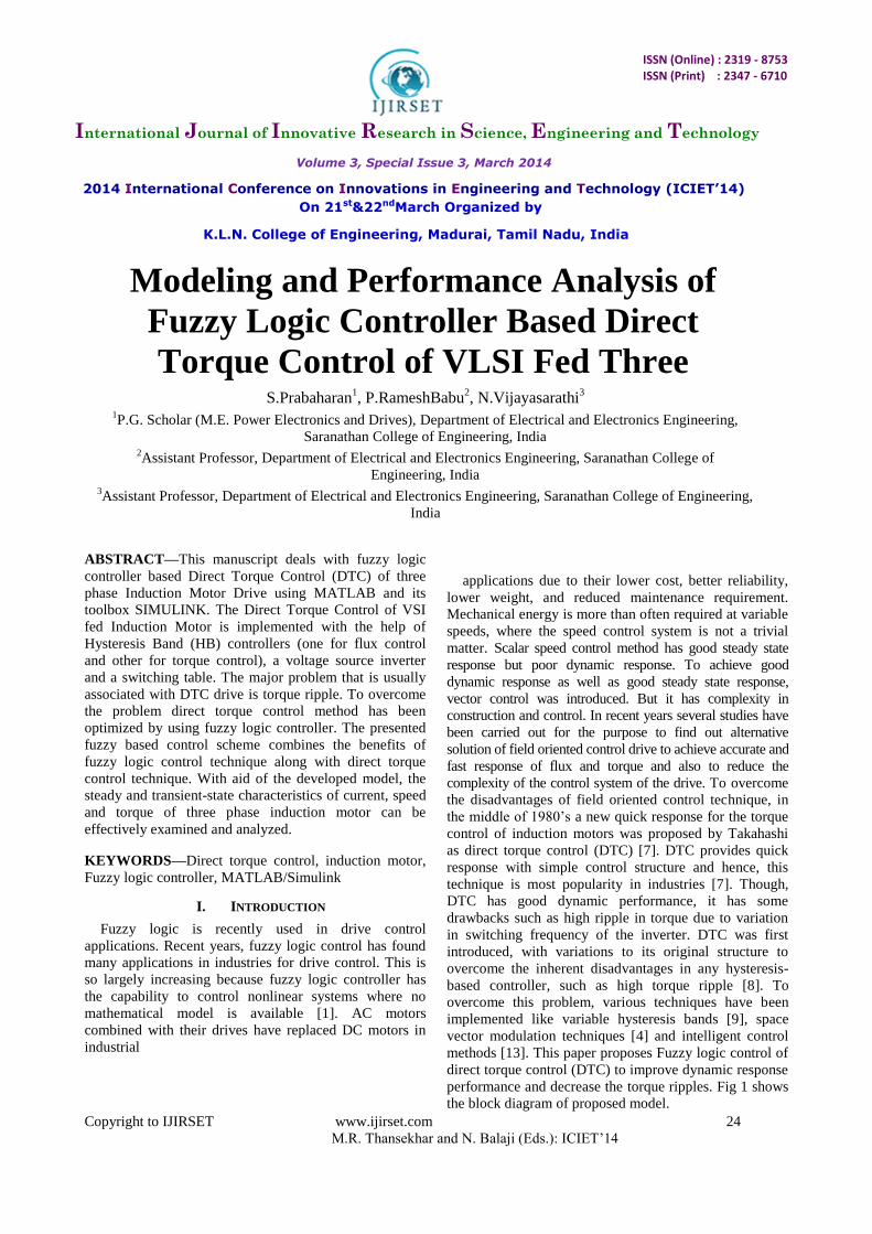
performance and decrease the torque ripples. Fig 1 shows
the block diagram of proposed model.
Modeling and Performance Analysis of
Fuzzy Logic Controller Based Direct
Torque Control of VLSI Fed Three
Phase Induction Motor S.Prabaharan1, P.RameshBabu
2, N.Vijayasarathi
3
1P.G. Scholar (M.E. Power Electronics and Drives), Department of Electrical and Electronics Engineering,
Saranathan College of Engineering, India 2Assistant Professor, Department of Electrical and Electronics Engineering, Saranathan College of
Engineering, India 3Assistant Professor, Department of Electrical and Electronics Engineering, Saranathan College of Engineering,
India
Modeling and Performance Analysis of Fuzzy Logic Controller Based Direct Torque Control
Copyright to IJIRSET www.ijirset.com 25
M.R. Thansekhar and N. Balaji (Eds.): ICIET’14
Fig.1 Block Diagram of Proposed Model
II. MODEL OF THREE PHASE INVERTER
A. Voltage Source Inverter
The most common voltage source inverter used in
DTC control is the six step inverter. A six step inverter
provides the variable frequency AC voltage input to the
induction motor in DTC method. The DC supply to the
inverter is provided either by a DC source or
rectifier.Each leg of the inverter has two switches one
connected to high side (+ve) of the DC and the other to
low side (-ve); only one of the two can be on at any
instant. When the high side gate signal is on the phase is
assigned to be1, and assigned 0 when the low side gate
signal is on. Considering the combinations of status of
phases a, b and c the inverter has eight switching modes
(Va, Vb, Vc = 000-111) two are zero voltage vectors V0
(000) and V7 (111) where the motor terminals is short
circuited and the others are nonzero voltage vectors V1 to
V6.
B. Inverter Model
Using the switching states of a, b, c the phase voltages
connected to the motor winding can be represented as
shown in Equation (1), (2) & (3),
(1)
(2)
(3)
The inverter block in MATLAB is created using the Equations (1), (2) & (3).
III. MODELLING OF INDUCTION MOTOR
The induction motor, which is the most widely used motor type in the industry, has been favored because of its good self-starting capability, simple and rugged structure, low cost and reliability, etc. Along with variable frequency inverters, induction motors are used in many adjustable speed applications. The concept of vector control has
opened up a new possibility that induction motors can be controlled to achieve dynamic performance as good as that of DC motors. In order to understand and analysis vector control, the dynamic model of the induction motor is necessary.
A. Induction Motor Modelling
A proper model for the three phase induction motor is
essential to simulate and study the complete drive system.
The model of induction motor is derived in arbitrary
reference frame by making reference speed as zero.
B. Variables in Arbitrary Reference Frame
The voltage equations of induction motor in arbitrary
reference frame given by,
𝑉𝑞𝑠 = 𝑟𝑠𝑖𝑞𝑠 + 𝜔𝜆𝑑𝑠 + 𝜌𝜆𝑞𝑠 (4)
𝑉𝑑𝑠 = 𝑟𝑠𝑖𝑑𝑠 − 𝜔𝜆𝑞𝑠 + 𝜌𝜆𝑑𝑠 (5)
𝑉𝑜𝑠 = 𝑟𝑠𝑖𝑜𝑠 + 𝜌𝜆𝑜𝑠 (6)
𝑉𝑞𝑟′ = 𝑟𝑟
′ 𝑖𝑞𝑟′ + 𝜔 − 𝜔𝑟 𝜆𝑑𝑟
′ + 𝜌𝜆𝑞𝑟′ (7)
𝑉𝑑𝑟′ = 𝑟𝑟
′ 𝑖𝑑𝑟′ − 𝜔 − 𝜔𝑟 𝜆𝑞𝑟
′ + 𝜌𝜆𝑑𝑟′ (8)
𝑉𝑜𝑟′ = 𝑟𝑟
′ 𝑖𝑜𝑟′ + 𝜌𝜆𝑜𝑟
′ (9)
The Flux linkage equation of three phase induction
motor in arbitrary reference frame given by,
𝜆𝑞𝑠=𝐿𝑙𝑠 𝑖𝑞𝑠 + 𝐿𝑚 𝑖𝑞𝑠 + 𝑖𝑞𝑟′ (10)
𝜆𝑑𝑠=𝐿𝑙𝑠 𝑖𝑑𝑠 + 𝐿𝑚 𝑖𝑑𝑠 + 𝑖𝑑𝑟′ (11)
𝜆𝑜𝑠=𝐿𝑙𝑠 𝑖𝑜𝑠 (12)
𝜆𝑞𝑟′ = 𝐿𝑙𝑟
′ 𝑖𝑞𝑟′ + 𝐿𝑚 (𝑖𝑞𝑠 + 𝑖𝑞𝑟
′ ) (13)
𝜆𝑑𝑟′ = 𝐿𝑙𝑟
′ 𝑖𝑑𝑟′ + 𝐿𝑚 (𝑖𝑑𝑠 + 𝑖𝑑𝑟
′ ) (14)
𝜆𝑜𝑟′ = 𝐿𝑙𝑟
′ 𝑖𝑜𝑟′ (15)
C. Current Equation
By solving flux linkage Equations (10) – (15) for
currents, we can obtain current equations as,
𝑖𝑞𝑠 =1
𝑋𝑙𝑠(𝜓𝑞𝑠 − 𝜓𝑚𝑞 ) (16)
𝑖𝑑𝑠 =1
𝑋𝑙𝑠(𝜓𝑑𝑠 − 𝜓𝑚𝑑 ) (17)
𝑖𝑜𝑠 =1
𝑋𝑙𝑠(𝜓𝑜𝑠) (18)
𝑖𝑞𝑟′ =
1
𝑋𝑙𝑟′ (𝜓𝑞𝑟
′ −𝜓𝑚𝑞 ) (19)
𝑖𝑑𝑟′ =
1
𝑋𝑙𝑟′ (𝜓𝑑𝑟
′ −𝜓𝑚𝑑 ) (20)
𝑖𝑜𝑟′ =
1
𝑋𝑙𝑟′ 𝜓𝑜𝑟
′ (21)
Where,
𝜓𝑚𝑞 = 𝑋𝑀(𝑖𝑞𝑠 + 𝑖𝑞𝑟′ ) (22)
𝜓𝑚𝑑 = 𝑋𝑀(𝑖𝑑𝑠 + 𝑖𝑑𝑟′ ) (23)
D. Electromagnetic Torque and Speed Equation
𝑇𝑒 = 3
2
𝑃
2
𝜓𝑑𝑠
𝜔𝑏𝑖𝑞𝑠 −
𝜓𝑞𝑠
𝜔𝑏𝑖𝑑𝑠 (24)
𝜔𝑟 = 𝑇𝑒−𝑇𝐿
2𝑃 𝑑𝑡 (25)
)2(3
)2(3
)2(3
cbaVdc
Vcn
cbaVdc
Vbn
cbaVdc
Van

Modeling and Performance Analysis of Fuzzy Logic Controller Based Direct Torque Control
Copyright to IJIRSET www.ijirset.com 26
M.R. Thansekhar and N. Balaji (Eds.): ICIET’14
E. Simulink Model of Induction Motor
The model of induction motor has been implemented
in MATLAB\SIMULINK with aid of equation (4) to (25).
The model has been simulated in arbitrary reference
frame by assigning zero to reference frame speed. Fig.2
shows the overall subsystem of induction motor
modeling.
Fig.2 Subsystem of induction motor model
IV. DIRECT TORQUE CONTROL
A. Principle of DTC
Direct torque control was developed by Takahashi and Depenbrock as an alternative to field-oriented control. In a direct torque controlled (DTC) induction motor drive supplied by a voltage source inverter, it is possible to control directly the stator flux linkage ѱs and the electromagnetic torque by the selection of an optimum inverter voltage vector. The selection of the voltage vector of the voltage source inverter is made to restrict the flux and torque error within their respective flux and torque hysteresis bands and to obtain the fastest torque response and highest efficiency at every instant.
B. Torque Expression of Induction Motor
The electromagnetic torque in the three phase
induction machines can be expressed as follows,
𝑇𝑒 = 3
2
𝑃
2 𝜓𝑠 × 𝐼𝑠 (26)
Where 𝜓𝑠is the stator flux, 𝐼𝑠 is the stator current and P
the number of poles. The previous equation can be
modified and expressed as,
𝑇𝑒 = 3
2
𝑃
2
𝐿𝑚
𝐿𝑟𝐿𝑠′ 𝜓𝑟 𝜓𝑠 𝑠𝑖𝑛𝛾 (27)
𝛾is the angle between fluxes.
From the above expression, when the rotor flux vector
𝜓𝑟 is constant and the stator flux vector 𝜓𝑠 is changed
incrementally, the angle between vectors 𝜓𝑟 and𝜓𝑠, 𝛾 is
incremented by ∆𝛾. The incremental ∆𝑇𝑒 expression is
given by,
∆𝑇𝑒 = 3
2
𝑃
2
𝐿𝑚
𝐿𝑟𝐿𝑠′ 𝜓𝑟 𝜓𝑠 + ∆𝜓𝑠 𝑠𝑖𝑛∆𝛾(28)
C. Control Strategy of DTC
The reference stator flux 𝜓𝑠∗and torque
Te∗magnitudes are compared with the respective
estimated values and the errors are processed through
hysteresis-band controller. The flux loop HB controller
has 2 levels of output according to the following
relations,
𝐻𝜓 = 1 𝑓𝑜𝑟𝐸𝜓 > +𝐻𝐵𝜓 (29)
𝐻𝜓 = −1 𝑓𝑜𝑟𝐸𝜓 < −𝐻𝐵𝜓 (30)
The torque loop controller has 3 levels of digital output
as per the following relations,
𝐻𝑇𝑒 = 1 𝑓𝑜𝑟𝐸𝑇𝑒 > +𝐻𝐵𝑇𝑒 (31)
𝐻𝑇𝑒 = −1 𝑓𝑜𝑟𝐸𝑇𝑒 < −𝐻𝐵𝑇𝑒 (32)
𝐻𝑇𝑒 = 0 𝑓𝑜𝑟−𝐻𝐵𝑇𝑒 < 𝐸𝑇𝑒 < +𝐻𝐵𝑇𝑒 (33)
The feedback flux 𝜓𝑠 and torque Te are calculated from
machine terminal voltages and currents. The signal
computation block also calculates the sector number S(k)
in which the flux vector 𝜓𝑠 lies. The voltage vector table
receives the input signals H𝜓 , HTe and S(k) and generates
the appropriate control voltage vector (switching states)
for the inverter using a lookup table, which is shown
inTable I.
TABLE I LOOKUP TABLE FOR DTC
D. DTC Simulink Model
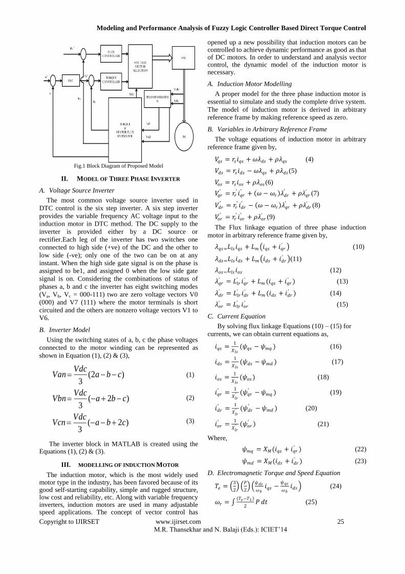
The complete model of DTC using SIMULINK is
shown in Fig.3.
Modeling and Performance Analysis of Fuzzy Logic Controller Based Direct Torque Control
Copyright to IJIRSET www.ijirset.com 27
M.R. Thansekhar and N. Balaji (Eds.): ICIET’14
Fig.3. DTC Simulink Model
V. FUZZY BASED DIRECT TORQUE CONTROL
A. Fuzzy Logic Controller
One of the reasons for the popularity of Fuzzy Logic
Controllers is its logical resemblance to a human
operator. It operates on the foundations of a knowledge
base which in turn rely upon the various if then rules,
similar to a human operator. Unlike other control
strategies, this is simpler as there is no complex
mathematical knowledge required. The FLC requires only
a qualitative knowledge of the system thereby making the
controller not only easy to use, but also easy to design.
B. Fuzzy Logic speed Regulator Model
The overall model for fuzzy logic based speed control
system for direct torque control induction motor drive is
shown in Fig.4. In the Fuzzy based DTC scheme of
voltage source inverter-fed induction motor drive system,
simultaneous control of the torque and the flux linkage
was required. So, the reference torque to DTC is fed from
speed loop of the IM drive as shown in Fig.5 which is
regulated using FLC. The input linguistic variables speed
error (E), change in speed error (CE) and output linguistic
variable Torque reference.
Fig.4. Fuzzy Speed Regulator
C. Fuzzification
In this stage, the input variables for the fuzzy control
speed regulator are speed error (E) and derivative of
speed error (CE) are converted in to fuzzy variables. The
triangular and trapezoidal shape membership functions
are chosen for the control variables. Speed error and
change in speed error variables are divided into seven
overlapping fuzzy sets NL (Negative Large), NM
(Negative Medium), NS (Negative Small), ZE (Zero), PS
(Positive Small), PM (positive Medium) and PL (Positive
Large). The division of seven error and change in error
fuzzy set is shown in Fig.5& Fig.6 respectively. The
output variable is reference torque which is divided into
nine overlapping fuzzy set NVL (Negative Very Large),
NL (Negative Large), NM (Negative Medium), NS
(Negative Small), ZE (Zero), PS (Positive Small), PM
(positive Medium), PL (Positive Large) and PVL
(Positive Very Large). The division of nine output torque
is shown in Fig.7.
Fig.5. Membership function for speed error
Fig.6. Membership function for change in speed error
Fig.7. Membership function for output
D. Knowledgebase and Interferance Stage
Knowledge base involves defining the rules
represented as IF-THEN statements governing the
relationship between input and output variables in terms
of membership functions. In this stage, the variables
Error (E) and Change in error (CE) are processed by an
inference engine that executes 49 rules (7x7) as shown in
Table II.
TABLE II
FUZZY CONTROL RULES
CE
E NL NM NS ZE PS PM PL
NL NVL NVL NVL NL NM NS ZE
NM NVL NVL NL NM NS ZE PS
NS NVL NL NM NS ZE PS PM
Modeling and Performance Analysis of Fuzzy Logic Controller Based Direct Torque Control
Copyright to IJIRSET www.ijirset.com 28
M.R. Thansekhar and N. Balaji (Eds.): ICIET’14
ZE NL NM NS ZE PS PM PL
PS NM NS ZE PS PM PL PVL
PM NS ZE PS PM PL PVL PVL
PL ZE PS PM PL PVL PVL PVL
E. Defuzzication
The most used defuzzification method is that of the
centre of attraction of balanced heights. Choice is based
on the latter owing to the fact that it is easy to implement
and does not require much calculation.
VI. SIMULATION RESULTS
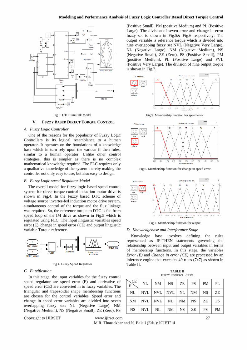
A. Output Characteristics of Induction Motor Model
The Induction motor model is run under no-load condition. The motor speed and torque under no-load are plotted in Fig.8, Fig.9 shows the stator flux of IM, The stator and rotor current under no-load condition are plotted in Fig.10 and Fig.11.
Fig.8. Torque and Speed Curve of IM at No Load
Fig.9. Stator flux of IM
Fig.10. Stator Current of IM at No Load
Fig.11. Rotor Current of IM at No Load
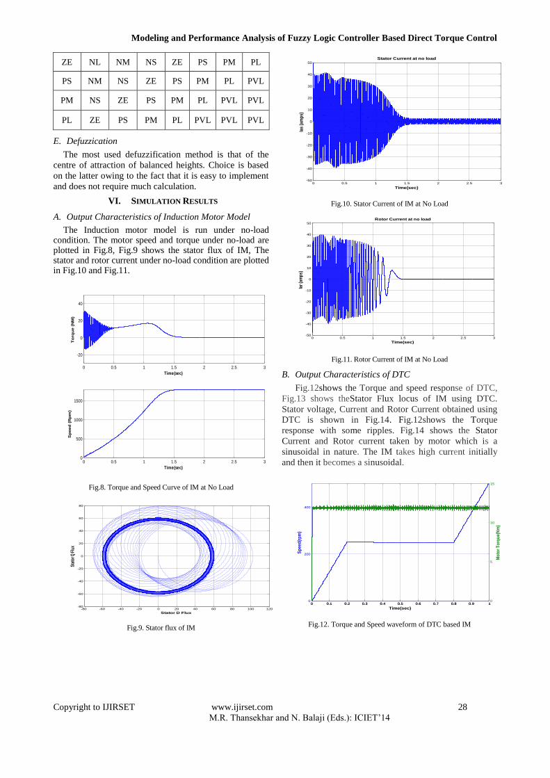
B. Output Characteristics of DTC
Fig.12shows the Torque and speed response of DTC,
Fig.13 shows theStator Flux locus of IM using DTC.
Stator voltage, Current and Rotor Current obtained using
DTC is shown in Fig.14. Fig.12shows the Torque
response with some ripples. Fig.14 shows the Stator
Current and Rotor current taken by motor which is a
sinusoidal in nature. The IM takes high current initially
and then it becomes a sinusoidal.
Fig.12. Torque and Speed waveform of DTC based IM
0 0.5 1 1.5 2 2.5 3
-20
0
20
40
Time(sec)
To
rqu
e (
NM
)
0 0.5 1 1.5 2 2.5 30
500
1000
1500
Time(sec)
Sp
eed
(R
pm
)
-80 -60 -40 -20 0 20 40 60 80 100 120-80
-60
-40
-20
0
20
40
60
80
Stator D Flux
Sta
tor Q
Flu
x
0 0.5 1 1.5 2 2.5 3-50
-40
-30
-20
-10
0
10
20
30
40
50
Time(sec)
Ias
(am
ps)
Stator Current at no load
0 0.5 1 1.5 2 2.5 3-50
-40
-30
-20
-10
0
10
20
30
40
50
Time(sec)
Iar
(am
ps)
Rotor Current at no load
0 0.1 0.2 0.3 0.4 0.5 0.6 0.7 0.8 0.9 10
200
400
Sp
eed
(rp
m)
Time(sec)
0 0.1 0.2 0.3 0.4 0.5 0.6 0.7 0.8 0.9 10
5
10
15
Mo
tor
To
rqu
e(N
m)
Modeling and Performance Analysis of Fuzzy Logic Controller Based Direct Torque Control
Copyright to IJIRSET www.ijirset.com 29
M.R. Thansekhar and N. Balaji (Eds.): ICIET’14
Fig.13. Stator flux locus using DTC
Fig.14. Stator Voltage, Current and Rotor Current Waveform of DTC
C. Output Characteristics of FDTC
Fig.15 shows the Torque and speed response of fuzzy
based Fuzzy based DTC.
Fig.15. Torque Response of Fuzzy based DTC
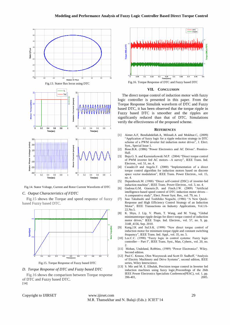
D. Torque Response of DTC and Fuzzy based DTC
Fig.16 shows the comparison between Torque response
of DTC and Fuzzy based DTC.
Fig.16. Torque Response of DTC and Fuzzy based DTC
VII. CONCLUSION
The direct torque control of induction motor with fuzzy
logic controller is presented in this paper. From the
Torque Response Simulink waveform of DTC and Fuzzy
based DTC, it has been observed that the torque ripple in
Fuzzy based DTC is smoother and the ripples are
significantly reduced than that of DTC. Simulations
verify the effectiveness of the proposed scheme.
REFERENCES
[1] Aimer.A.F, Bendiabdellah.A, Miloudi.A and Mokhtar.C, (2009)
―Application of fuzzy logic for a ripple reduction strategy in DTC
scheme of a PWM inverter fed induction motor drives‖, J. Elect. Syst., Special Issue 1.
[2] Bose.B.K. (1986) "Power Electronics and AC Drives". Prentice-
Hall. [3] Buja.G. S. and Kazmierkowski M.P. (2004) ―Direct torque control
of PWM inverter fed AC motors—A survey‖, IEEE Trans. Ind.
Electron., vol. 51, no. 4.
[4] Casadei.D and Angelo.T. (2000) ―Implementation of a direct
torque control algorithm for induction motors based on discrete
space vector modulation‖, IEEE Trans. Power Electron., vol. 15, no. 4.
[5] Depenbrock.M. (1988) ―Direct self-control (DSC) of inverter-fed
induction machine‖, IEEE Trans. Power Electron., vol. 3, no. 4. [6] Gadoue.G.M, Giaouris.D, and Finch.J.W. (2009) ―Artificial
intelligence-based speed control of DTC induction motor drives—
A comparative study‖, Elect. Power Syst. Res., vol. 79, no. 1 [7] Isao Takahashi and Toshihiko Noguchi, (1986) ―A New Quick-
Response and High Efficiency Control Strategy of an Induction
Motor‖, IEEE Transactions on Industry Applications, Vol.1A-22.No.5.
[8] K. Shyu, J. Lip, V. Pham, T. Wang, and M. Yang, "Global
minimumtorque ripple design for direct torque control of induction motor drives," IEEE Traps. Ind. Electron., vol. 57, no. 9, pp.
3148_4156, Sep. 2010.
[9] Kang.J.K and Sul.S.K. (1999) ―New direct torque control of induction motor for minimum torque ripple and constant switching
frequency‖, IEEE Trans. Ind. Appl., vol. 35, no. 5.
[10] Lee.C.C. (1990) ―Fuzzy logic in control systems: Fuzzy logic controller— Part I‖, IEEE Trans. Syst., Man, Cybern., vol. 20, no.
2.
[11] Mohan, Undeland, Robbins, (1989) ―Power Electronics". Wiley. Second edition.
[12] Paul C. Krause, Olen Wasynzcuk and Scott D. Sudhoff, ―Analysis
of Electric Machinery and Drive Systems‖, second edition, IEEE series, Wiley Interscience.
[13] S. Mir and M. E. Elbuluk, Precision troque control in Inverter fed
induction machines using fuzzy logic,Proceedings of the 26th IEEE Power Electronics Specialists Conference(PESC), vol. 1, pp.
396-401, 2005.
[14]
-80 -60 -40 -20 0 20 40 60 80-80
-60
-40
-20
0
20
40
60
80
Stator D Flux
Sta
tor
Q F
Lu
x
0 0.2 0.4 0.6 0.8 10
5
10
15
Mo
tor T
orq
ue(N
m)
Time(sec)
0 0.2 0.4 0.6 0.8 1
10111213
0 0.2 0.4 0.6 0.8 1-300
-200
-100
0
100
200
300
Time(sec)
Sta
tor P
hase V
olt
ag
e (
vo
lts)
0 0.2 0.4 0.6 0.8 1-50
0
50
Time(sec)
Sata
tor C
urren
t (a
mp
s)
0 0.2 0.4 0.6 0.8 1-50
0
50
Time(sec)
Ro
ro
r C
urren
t (a
mp
s)
TL
Tref
0 0.1 0.2 0.3 0.4 0.5 0.6 0.7 0.8 0.9 10
200
400
Sp
eed
(rp
m)
Time(sec)
0 0.1 0.2 0.3 0.4 0.5 0.6 0.7 0.8 0.9 10
5
10
15
Mo
tor
To
rqu
e(N
m)
0 0.05 0.1 0.15 0.2 0.25 0.3 0.35 0.4 0.45 0.510
12
To
rqu
e (N
M) a
t DT
C
Time(sec)
0 0.05 0.1 0.15 0.2 0.25 0.3 0.35 0.4 0.45 0.5
12
14
To
rqu
e (N
M) a
t FD
TC
DTC
FUZZY