Modeling and Experimental Studies of Coating Delamination ...
10
Modeling and Experimental Studies of Coating Delamination of Biodegradable Magnesium Alloy Cardiovascular Stents Chenxin Chen, †,‡,§ Jinyun Tan, †,⊥ Wei Wu,* ,§,∥ Lorenza Petrini, # Lei Zhang, ‡ Yongjuan Shi, ‡ Emanuele Cattarinuzzi, § Jia Pei, ‡ Hua Huang, ‡ Wenjiang Ding, ‡ Guangyin Yuan,* ,‡ and Francesco Migliavacca § ‡ National Engineering Research Center of Light Alloy Net Forming & State Key Laboratory of Metal Matrix Composite, Shanghai Jiao Tong University, 800 Dongchuan Road, Shanghai, China, 200240 § Laboratory of Biological Structure Mechanics (Laboratories), Department of Chemistry, Materials and Chemical Engineering “Giulio Natta”, and # Department of Civil and Environmental Engineering, Politecnico di Milano, Piazza Leonardo da Vinci, 32, Milan 20133, Italy ⊥ Department of Vascular Surgery, Huashan Hospital of Fudan University, No. 12 Mid-Wulumuqi Road, Shanghai 200040, China ∥ Department of Mechanical Engineering, The University of Texas at San Antonio, One UTSA Circle, San Antonio, Texas 78249-0669, United States ABSTRACT: Biodegradable magnesium alloy stents exhibit deficient corrosion period for clinic applications, making the protective polymer coating more crucial than drug-eluting stents with the permanent metal scaffold. We implemented a cohesive method based on a finite element analysis method to predict the integrity of adhesive between coating and stent during the crimping and deployment. For the first time, the three-dimensional quantitative modeling reveals the process of polymer coating delamination and stress concentration. The fracture and microcracks of coatings were consistent with the simulation result, confirmed by the scanning electron microscopy observation. Moreover, we analyzed four possible factors, i.e., stent design, strut material, coating polymer, and thickness of the coating, affecting the stent-coating damage and the distribution of the stress in coatings. Mg−Nd−Zn−Zr alloy with lower yield strength performed a more uniform strain distribution and more favorable adhesion of the coating than the commercial magnesium alloy AZ31. Shape optimization of stent design improves the strain and stress distribution of coating remarkably, avoiding coating delamination. Additionally, PLGA coating with lower elastic modulus and yield strength tends to follow the deformation of the stent better and to adhere on the surface more tightly, compared to PLLA polymer. A reduction in coating thickness and an increase in the strength of stent-coating interface improve the resistance to delamination. Our framework based on cohesive method provides an in-depth understanding of stent-coating damage and shows the way of computational analyses could be implemented in the design of coated biodegradable magnesium stents. KEYWORDS: polymer coating, biodegradable magnesium alloy stent, delamination, cohesive zone method, finite element analysis ■ INTRODUCTION In recent years, drug-eluting stents have become the standard therapy for percutaneous coronary intervention (PCI), to cure the treatment of coronary artery stenosis. 1,2 Bioabsorbable polymer-based vascular scaffolds (BVS) and biodegradable magnesium alloy stents (BMS) were developed to overcome the shortcomings of drug-eluting stents, leaving no permanent implant with short-term support and long-term degradation to restore vessel function, avoiding a series of disadvantages. 3 However, a series of clinical results of BVS show that the bioabsorbable polymer-based scaffold has noninferior rates of target lesion failure at 1 year to DES, but with a higher incidence of device thrombosis than the metallic stent through 2-year and 3-year clinical follow-ups. 4−6 Considering the differentiating failure modes in metallic and polymeric devices, BVS not only degrade but also possess significant localized structural irregularities that cause asymmetric degradation, which could be an explanation for the clinical results. 7 Compared to the bioabsorbable aliphatic polymers of BVS, such as poly(L-lactic acid) (PLLA) and poly(D,L-lactic-co- glycolic acid) (PLGA), some of the biodegradable magnesium alloys have superior mechanical properties and uniform degradation process, 8−11 which might lead to better long- term clinical behavior than that for BVS. However, the degradation rates of Mg alloys are still too high at the initial stage of implantation for the clinical requirements. 12,13 On the Received: June 18, 2018 Accepted: September 24, 2018 Published: September 24, 2018 Article pubs.acs.org/journal/abseba Cite This: ACS Biomater. Sci. Eng. 2018, 4, 3864-3873 © 2018 American Chemical Society 3864 DOI: 10.1021/acsbiomaterials.8b00700 ACS Biomater. Sci. Eng. 2018, 4, 3864−3873 Downloaded via UNIV OF NEBRASKA MEDICAL CTR on April 16, 2020 at 21:47:24 (UTC). See https://pubs.acs.org/sharingguidelines for options on how to legitimately share published articles.
Transcript of Modeling and Experimental Studies of Coating Delamination ...

Modeling and Experimental Studies of Coating Delamination ofBiodegradable Magnesium Alloy Cardiovascular StentsChenxin Chen,†,‡,§ Jinyun Tan,†,⊥ Wei Wu,*,§,∥ Lorenza Petrini,# Lei Zhang,‡ Yongjuan Shi,‡
Emanuele Cattarinuzzi,§ Jia Pei,‡ Hua Huang,‡ Wenjiang Ding,‡ Guangyin Yuan,*,‡
and Francesco Migliavacca§
‡National Engineering Research Center of Light Alloy Net Forming & State Key Laboratory of Metal Matrix Composite, ShanghaiJiao Tong University, 800 Dongchuan Road, Shanghai, China, 200240§Laboratory of Biological Structure Mechanics (Laboratories), Department of Chemistry, Materials and Chemical Engineering“Giulio Natta”, and #Department of Civil and Environmental Engineering, Politecnico di Milano, Piazza Leonardo da Vinci, 32,Milan 20133, Italy⊥Department of Vascular Surgery, Huashan Hospital of Fudan University, No. 12 Mid-Wulumuqi Road, Shanghai 200040, China∥Department of Mechanical Engineering, The University of Texas at San Antonio, One UTSA Circle, San Antonio, Texas78249-0669, United States
ABSTRACT: Biodegradable magnesium alloy stents exhibitdeficient corrosion period for clinic applications, making theprotective polymer coating more crucial than drug-elutingstents with the permanent metal scaffold. We implemented acohesive method based on a finite element analysis method topredict the integrity of adhesive between coating and stentduring the crimping and deployment. For the first time, thethree-dimensional quantitative modeling reveals the process ofpolymer coating delamination and stress concentration. Thefracture and microcracks of coatings were consistent with thesimulation result, confirmed by the scanning electron microscopy observation. Moreover, we analyzed four possible factors, i.e.,stent design, strut material, coating polymer, and thickness of the coating, affecting the stent-coating damage and thedistribution of the stress in coatings. Mg−Nd−Zn−Zr alloy with lower yield strength performed a more uniform straindistribution and more favorable adhesion of the coating than the commercial magnesium alloy AZ31. Shape optimization ofstent design improves the strain and stress distribution of coating remarkably, avoiding coating delamination. Additionally,PLGA coating with lower elastic modulus and yield strength tends to follow the deformation of the stent better and to adhereon the surface more tightly, compared to PLLA polymer. A reduction in coating thickness and an increase in the strength ofstent-coating interface improve the resistance to delamination. Our framework based on cohesive method provides an in-depthunderstanding of stent-coating damage and shows the way of computational analyses could be implemented in the design ofcoated biodegradable magnesium stents.KEYWORDS: polymer coating, biodegradable magnesium alloy stent, delamination, cohesive zone method, finite element analysis
■ INTRODUCTION
In recent years, drug-eluting stents have become the standardtherapy for percutaneous coronary intervention (PCI), to curethe treatment of coronary artery stenosis.1,2 Bioabsorbablepolymer-based vascular scaffolds (BVS) and biodegradablemagnesium alloy stents (BMS) were developed to overcomethe shortcomings of drug-eluting stents, leaving no permanentimplant with short-term support and long-term degradation torestore vessel function, avoiding a series of disadvantages.3
However, a series of clinical results of BVS show that thebioabsorbable polymer-based scaffold has noninferior rates oftarget lesion failure at 1 year to DES, but with a higherincidence of device thrombosis than the metallic stent through2-year and 3-year clinical follow-ups.4−6 Considering thedifferentiating failure modes in metallic and polymeric devices,
BVS not only degrade but also possess significant localizedstructural irregularities that cause asymmetric degradation,which could be an explanation for the clinical results.7
Compared to the bioabsorbable aliphatic polymers of BVS,such as poly(L-lactic acid) (PLLA) and poly(D,L-lactic-co-glycolic acid) (PLGA), some of the biodegradable magnesiumalloys have superior mechanical properties and uniformdegradation process,8−11 which might lead to better long-term clinical behavior than that for BVS. However, thedegradation rates of Mg alloys are still too high at the initialstage of implantation for the clinical requirements.12,13 On the
Received: June 18, 2018Accepted: September 24, 2018Published: September 24, 2018
Article
pubs.acs.org/journal/absebaCite This: ACS Biomater. Sci. Eng. 2018, 4, 3864−3873
© 2018 American Chemical Society 3864 DOI: 10.1021/acsbiomaterials.8b00700ACS Biomater. Sci. Eng. 2018, 4, 3864−3873
Dow
nloa
ded
via
UN
IV O
F N
EB
RA
SKA
ME
DIC
AL
CT
R o
n A
pril
16, 2
020
at 2
1:47
:24
(UT
C).
See
http
s://p
ubs.
acs.
org/
shar
ingg
uide
lines
for
opt
ions
on
how
to le
gitim
atel
y sh
are
publ
ishe
d ar
ticle
s.
one hand, applying polymer coatings on Mg alloys couldreduce the degradation rate of Mg and carry antiproliferativedrugs to avoid initial stenosis.14−17 In the light of observedcoating damages on DES,18,19 the integrity and cohesion ofpolymer coating on BMS are more important, as thedelamination or fracture of the coating would expose the Mgalloy strut surface and accelerate the localized corrosion rate,which might lead to vascular restenosis and prevent vesselendothelialization.19−21
Finite element analysis (FEA) has been widely used to guidestent design and simulate the deformation and degradation ofthe implanted device.22−26 A cohesive zone method (CZM)based on a peeling model could efficiently reflect the adhesiveproperty between two surfaces,27,28 for example, stent andcoating. A series of 2D CZM simulation and experiments havebeen conducted for stainless drug-eluting stents to predict andexplicate a variety coating-damages, including delamination,webbing, and buckling.29−31 The CZM has also been appliedto design and analyze coated biodegradable magnesiumstent.26,32 Nevertheless, the previous simulations of theadhesion of polymer coatings and metallic stents are basedon two-dimensional models. The specific deformation ofcoating in the thickness direction of stent and the effects ofstent-balloon contact cannot be evaluated in such a model.The present study aims to develop a 3D model to simulate
the deformation process and stress distribution of polymercoatings, meanwhile predicting and evaluating the coatingsintegrity and delamination tendency. This work is carried outconsidering two Mg alloys: commercial Mg alloy AZ31 andMg−Nd−Zn−Zr (abbr. JDBM), a magnesium alloy made bywith excellent mechanical properties, and uniform degradationbehavior.33 High-quality microtubes,34 stents,35 and polymercoatings16,17 used in this work are progressed by the authors.The 3D FEA modeling for polymer-coated magnesium stentusing CZM is first put forward to date.
■ MATERIALS AND METHODSStent Samples and Materials Properties. The chemical
composition and processing of two magnesium alloy tubes, AZ31and JDBM, can be found in our previous work.34 Two designs, thestent with a sine-wave ring (abbr. SIN) and shape-optimized (abbr.OPT) stent designed by our group, are shown in Figure 1. Therepeated units captured from each design to build the FEA mode areshown. The outer diameter and thickness of the stents were 3.00 mmand 160 μm, respectively.
The AZ31 tubes were cut into SIN stents (abbr. AZ31-SIN), whilethe JDBM tubes were cut into OPT stents (abbr. JDBM-OPT). Toadjust the unsmooth surface caused by the laser cutting, we polishedthe stents with the electrochemical method and then washed them viaultraphonic ethanol cleaning before drying.34 After fluoride treatmentof both AZ31-SIN and JDBM-OPT stents, the stents were preparedusing an ultrasonic spray-coating technology as described in ourprevious work.17 Poly(l-lactic acid) (abbr. PLLA) and poly(lactic-co-glycolic acid) (abbr. PLGA) were used for stent coating spray. A totalof 9 stents of three different groups, PLLA-coated AZ31-SIN, PLGA-coated AZ31-SIN, and PLGA-coated JDBM-OPT stents werecrimped on the fold-balloon with an outer diameter of 1.3 mm. Weinflated the balloon at the pressure of 8 atm to expand the coatedstents with an outer diameter of 3.2 mm in the air. PLLA and PLGAwith a weight-average molecular weight of ∼100 000 g/mol werebought from Jinan Daigang Biomaterial Co., Ltd. (Shandong, China).PLGA is in a mole ratio of LA/GA = 50/50. No drug is contained inthose polymer coatings.
In our FEA model, JDBM and AZ31 alloy were used as stentplatform materials, whereas PLLA and PLGA were used for thecoating materials. The stress−strain curves of JDBM and AZ31 wereobtained from tensile mechanical tests of microtubes.34 The polymers’mechanical properties were taken from the study by Paryab et al.36
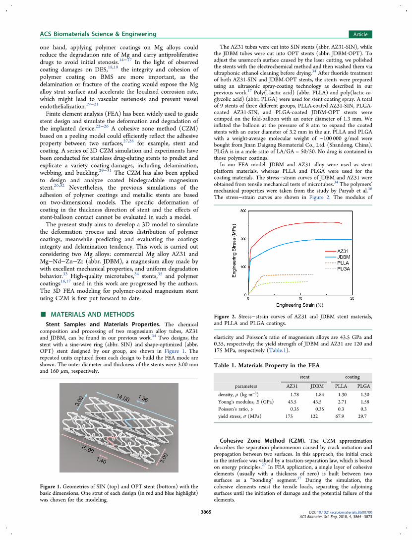
The stress−strain curves are shown in Figure 2. The modulus of
elasticity and Poisson’s ratio of magnesium alloys are 43.5 GPa and0.35, respectively; the yield strength of JDBM and AZ31 are 120 and175 MPa, respectively (Table.1).
Cohesive Zone Method (CZM). The CZM approximationdescribes the separation phenomenon caused by crack initiation andpropagation between two surfaces. In this approach, the initial crackin the interface was valued by a traction-separation law, which is basedon energy principles.27 In FEA application, a single layer of cohesiveelements (usually with a thickness of zero) is built between twosurfaces as a “bonding” segment.37 During the simulation, thecohesive elements resist the tensile loads, separating the adjoiningsurfaces until the initiation of damage and the potential failure of theelements.
Figure 1. Geometries of SIN (top) and OPT stent (bottom) with thebasic dimensions. One strut of each design (in red and blue highlight)was chosen for the modeling.
Figure 2. Stress−strain curves of AZ31 and JDBM stent materials,and PLLA and PLGA coatings.
Table 1. Materials Property in the FEA
stent coating
parameters AZ31 JDBM PLLA PLGA
density, ρ (kg m−3) 1.78 1.84 1.30 1.30Young’s modulus, E (GPa) 43.5 43.5 2.71 1.58Poisson’s ratio, ν 0.35 0.35 0.3 0.3yield stress, σ (MPa) 175 122 67.9 29.7
ACS Biomaterials Science & Engineering Article
DOI: 10.1021/acsbiomaterials.8b00700ACS Biomater. Sci. Eng. 2018, 4, 3864−3873
3865

A bilinear traction−separation law is applied in the CZM in thisstudy. The pure model constitutive law of traction−separationresponses in the normal direction and tangential direction isillustrated in Figure 3. This model assumes a linear elastic behaviorbefore damage in the interface. Once an initiation criterion σn/σt isreached, the damage is initiated. Under continuous loading, damagespreads until the final fracture occurs.The traction−separation constitutive relationship in normal
separation can be expressed as
lmoooooo
noooooo
K
D K
,
(1 ) ,
0,
n
n f
f
σ
δ
δ
δ δ
δ δ δ
δ δ
= −
≤
≤ ≤
≥ (1)
and
l
m
oooooooo
n
oooooooo
D
0,
,
1,
n
f n
n
n f
f
δ δδ δ
δ δ
δ δ δ
δ δ
=−−
≤
≤ ≤
≥(2)
where σ and δ are the stress and displacement of separation. δn andδfare the initial damage displacement and fracture displacement. D is adamage variable, overall scalar stiffness degradation, ranging from 0 to1. K is the initial interfacial stiffness, which is treated as a penaltyparameter and does not represent a physically measurable quantity.28
The critical energy release rate Gc can be calculated by
G12c n fσ δ=
(3)
where σn is the interfacial critical stress.In eqs 1−3, we assume that σn = σt, and δn = δt, so that the stresses,
displacements, and critical fracture energy can be represented for thecomponents in normal and tangential directions. In this simulation,the adhesion data is captured in an enhanced 90° peeling test, whichis reported in our previous work by a penalty function method.28,38
The size of the peeling samples is 15 mm in length and 1 mm inwidth, whereas the critical release rate of the interface is 58.2 J/m2. Apeeling test with simultaneous imaging of the samples has beencarried out by means of in-house-developed microtensile equip-ment.39
Finite Element Model. Considering the symmetry of the stent, aone-sixth ring was developed for both SIN stent and OPT stent.Moreover, the influence of the balloon−stent interaction on coatingdelamination was investigated.A theta-symmetry (Figure 4a) was applied to the nodes of the two
distal surfaces of the structure and a radial displacement is applied tothe balloon. The coating was modeled with a series thickness of 5, 10,and 15 μm covering the stents. Between the stent and the coating, and
at the edge of coating, there is a monolayer of cohesive elements ofzero thickness, as shown in Figure 4c. The balloon was modeled witha cylindrical surface. A general contact algorithm was applied tosimulate interaction between coating and stent interaction, betweenabluminal side of coating and crimping device, and between luminalside of the coating and the balloon, setting a normal hard contact anda tangential behavior with a coefficient of friction of 0.2. In this way,the crimping and expansion deformation of the stent are driven by theinner and outer shells (Table 2).
The coating and stent were meshed with eight-node brick elementswith reduced integration (C3D8R), 10 and 2 layers in the stent andcoating thickness direction, respectively. The cohesive layer wasmeshed with eight-node tridimensional cohesive elements(COH3D8) with an average max edge length of 15 μm. And theballoon was meshed using four nodes surface elements with reducedintegration (SFM3DR). The simulations were run using theABAQUS/Explicit code 6.14 (Dassault Systemes, Velizy-Villacoublay,France).
SEM Characterization. The surface morphology of the PLLA andPLGA coatings were examined by scanning electron microscopy(SEM, JSM 7600F, Japan). Before SEM observation, samples werecoated with a layer of gold with a thickness of ∼20 nm by a sputtercoater (SHINKKU VD MSP-1S, Japan).
Figure 3. Schematic of the bilinear traction-separation law used for the cohesive elements, in the (a) normal and (b) tangential direction. Yellowand gray cubes stand for coating and stent elements, respectively. Red arrows show the traction direction.
Figure 4. (a) FEA model of stent unit and two driving cylindricalsurfaces, with boundary conditions in the circumferential directionand displacement loading in the radial direction. (b) Cross-section ofthe model includes stent (blue) and coating (yellow) meshes, and (c)cohesive zone element (red) between with zero thickness.
ACS Biomaterials Science & Engineering Article
DOI: 10.1021/acsbiomaterials.8b00700ACS Biomater. Sci. Eng. 2018, 4, 3864−3873
3866

Objectives of the Study. First, three FEA scenarios weresimulated and validated by experiments: the AZ31-SIN stent coatedwith PLLA and PLGA, respectively, and the JDBM-OPT stent coatedwith PLGA. Only two stent platforms were provided because of thedifficulty in manufacturing stent samples. The thickness of thecoatings is 10 μm, which is calculated by the mass increment afterultrasonic spray-coating. In this section, the critical energy release rateGc of 58.2 J/m2 is captured by the peeling test mentioned previously.Second, for one stent, namely PLLA-coated AZ31-SIN stent, the
process of delamination was further investigated. The traction of thecohesive element layer during crimping and expansion were plottedand divided in the local coordinate system. The sequence of damagingand deleting the cohesive element during the process of coatingdebonding were evaluated.Third, as different coating material properties and stent materials
influence the adhesion interface states and deformations of thecoatings, the influence of stent design and material on coatingdeformation behavior was investigated. For the 3D models, we buildup three different stent platforms: AZ31-SIN stent, JDBM-SIN stent,
and JDBM-OPT stent, coated with PLLA with 10 μm thickness. Topresent the various behavior of coating deformation on a differentplatform, we assumed another smaller interface fracture energy Gc of43.5 J/m2.
Furthermore, to investigate the influence of coating materials andthickness on coating peeling, we combined two materials (PLLA andPLGA) and three coating thicknesses (5, 10, and 15 μm) with thethree stent platforms (AZ31-SIN, JDBM-SIN, and JDBM-OPT) for18 simulation scenarios. The range of coating thickness is based onthe current commercial stent coating thicknesses, and can provide areference for future coating process optimization. For each scenario, acritical interface fracture energy Gc′, the minimum valve of Gc to avoidcoating delamination during the expansion step, was calculated andcompared to other scenarios.
■ RESULTS
Simulation Predicting and Experiment Validation.Three FEA scenarios were simulated and validated byexperiments, as shown in Figure 5. The first row is the SINstent coated with PLLA (a−c), the second row is the samestent coated with PLGA (d−f) and the last row is the OPTstent coated with PLGA (g−i). All three groups of stents werecrimped to an outer diameter of 1.3 mm and after that beexpanded to an inner diameter of 3.1 mm.The distributions of the maximum principal stress of the
PLLA coating are shown in two different perspectives (Figure5a, b). The predicted fractures and delamination of PLLAcoatings in SIN stent were similar to the experiment (Figure5c). As shown in Figure 5d, the PLGA coating in the SIN stentshould remain integrated after the expansion, which was also
Table 2. Boundary Conditions for Stent-CoatingDeformation
outer surface (crimping) inner surface (expansion)
time (s) diameter (mm) contact state diameter (mm) contact state
0 3.1 √0.5 3.0 √1.5 1.3 √ 1.1 √2.0 1.1 √3.5 3.1 √4.0
Figure 5. Maximum principal stress distributions on the polymer coatings after expansion and the SEM images for coating delamination (scale barrepresents 100 μm). (a, b) The delamination of PLLA coating on the AZ31-SIN stent is consistent with (c) the SEM image, where the arrowindicates the delamination phenomenon. The PLGA coatings maintained their integrity on the (d) JDBM-SIN stent and (g) JDBM-OPT stent,whereas the coating on the SIN stent has higher (e) stresses and (f) microcracks with respect to (h, i) the OPT stent, where the arrow indicates themicrocracks.
ACS Biomaterials Science & Engineering Article
DOI: 10.1021/acsbiomaterials.8b00700ACS Biomater. Sci. Eng. 2018, 4, 3864−3873
3867

confirmed by SEM observations (Figure 5f). Furthermore, thesimulation found coating stress concentration near the insideedge of the stent bow (Figure 5d, e). In the SEM observation,
dense microcracks exhibit a similar pattern to the contour ofthe stress distribution in the same region (Figure 5f). Thedensity of the microcracks looked consistent with the
Figure 6. Maximum principal stress distributions of polymer coating after (a) crimping and (b) expansion. Three collinear dots show the locationsof representative nodes of the cohesive layer, indicated by the black arrow in a. The coating delamination is indicated by the black arrow in b. (c)Normal traction (σn), (d) tangential traction in the radial direction (τr), and (e) tangential traction in the circumferential direction (τθ) for thethree nodes, respectively. (f) Sequence of stiffness degradation distribution (SDEG) of the cohesive elements and maximum principal stressdistribution of the coating elements during the initial period of the delamination.
ACS Biomaterials Science & Engineering Article
DOI: 10.1021/acsbiomaterials.8b00700ACS Biomater. Sci. Eng. 2018, 4, 3864−3873
3868

distribution of maximum principal stress on the coatingsurface.The comparison between the PLGA coatings in SIN and
OPT stent (Figure 5d, e) shows that the coating in the OPTstent has a much lower peak stress than that in the SIN stent(33 MPa vs 49 MPa), and no microcracks can be observed inSEM image (Figure 5i).Stress Fluctuation during Crimping and Expansion.
The deformation and maximum principal stress distribution ofPLLA coating in SIN stent after crimping and expansion areshown in Figure 6. Although the coating remained intact aftercrimping (Figure 6a), it had delamination inside the strut bowand was fractured at the inside edge of the coating after theexpansion (Figure 6b).Three collinear nodes were selected from the cohesive layer
at luminal (red), midplane (blue), and abluminal (green)location to analyze the stress in the cohesive layer. Accordingto the local coordinate system defined in Figure 5b (n, r, and θin normal, radial, and circumferential direction), the tractionsof these nodes in the three directions are shown in Figure 5c−e, respectively. The normal traction σn of the three nodes werein compressive state during crimping and recoil. Duringexpansion σn of these nodes changed to a tensile state andincreased rapidly, and the midplane node reached the Tmax at2.80 s, then the corresponding CZE was damaged and deletedin sequence. The peak σn of the luminal and the abluminalnode reached are 0.96Tmax and 0.82Tmax, respectively. Thisresult shows that the normal traction is not the only reason forthe coating delamination at the luminal and abluminallocations. As for the tangential traction in the radial direction(τr), the midplane node reached a peak value of 0.14Tmaxduring the expansion (Figure 6d). However, τr of the luminalnode reached −Tmax at 2.85 s, almost at the same time itreached the peak value of σn. The corresponding CZEs werethen damaged and coating delamination occurred at the
luminal location. The tangential traction τr of the abluminalnode reached 0.84Tmax at 2.65 s, earlier than the normaltraction got the peak value. In the circumference direction, thetangential tractions (τθ) for the three nodes fluctuated aroundzero because of the geometrical symmetry (Figure 6e).The sequence of stiffness degradation distribution of
cohesive elements and maximum principal stress distributionof the coating elements during the initial period of thedelamination revealed the detailed process of cohesiveelements degradation (Figure 6f). The midplane node andluminal node got damaged at 2.85 s, but the cohesive layer wasstill intact. The initial debond of coating appeared in theluminal and middle zone at 2.90 s. Subsequently, the debondof coating spread around and the concentration of stressoccurred around the abluminal node at 3.00 s. In the nexttimeframe, all of the cohesive elements on the symmetric linewere deleted and the delamination of coating took place at3.05 s.
Influence of Stent Design and Material on CoatingDeformation. As for the influence of the stent material anddesign on the coating deformation, the first column of Figure 7shows the surface morphology and stress distribution of thePLLA coating after crimping and expansion of the threedifferent stent platforms (AZ31-SIN stent, JDBM-SIN stent,and JDBM-OPT stent). The PLLA coating on the AZ31-SINstent delaminated at both inside and outside edge of the bowafter being deployed (Figure 7a). When the material ischanged from AZ31 alloy to JDBM, the coating on JDBM-SINis delaminated at the inside edge, whereas the outside edge ofcoating remained intact (Figure 7e). On the other hand, whenthe stent material is JDBM but the stent design is changed toOPT, all the PLLA coating on JDBM-OPT stent remains intactafter balloon expansion and recoil (Figure 7i). The peak valueof the maximum principal stress of coatings decreased from76.2 to 56.73 MPa (Figure 7e, i).
Figure 7.Maximum principal stress distributions of PLLA coatings with a thickness of 10 μm on the (a) AZ31-SIN stent (e), JDBM-SIN stent and(i) JDBM-OPT stent expanded to the inner diameter of 3.1 mm and recoiled, with an interface fracture energy Gc of 43.5 J/m
2. The max principalstress in the stents is shown in panels b, f, and j. The equivalent plastic strain (PEEQ) distributions of the abluminal strut surface are shown inpanels c, g, and k, and for the lateral strut surface in panels d, h, and l. Two legends are used to highlight the difference in abluminal and lateralsurface; the locations of maximum PEEQ are marked by three red arrows.
ACS Biomaterials Science & Engineering Article
DOI: 10.1021/acsbiomaterials.8b00700ACS Biomater. Sci. Eng. 2018, 4, 3864−3873
3869
To further disclose the influence of stent material anddesign, the struts of AZ31-SIN, JDBM-SIN and JDBM-OPTstent were isolated to compare the distribution of maximumprincipal stress (S. Max. Principal) and equivalent plastic strain(PEEQ) (Figure 7b, c, f, g) in the stent after expansion andrecoil. The same design and the same elastic modulus of alloysgenerated similar patterns of stress and strain for AZ31-SINand JDBM-SIN stent. The peak values of the max principalstress of AZ31-SIN and JDBM-SIN stent are 245.3 and 203.6MPa, respectively. And the corresponding peak values ofequivalent plastic strain are 0.779 and 0.633, respectively.Meanwhile, the locations of peak stress are located at thecenter part of the strut corner and the locations of peak plasticstrain are located at the symmetric line of lateral surface(Figure 7d, h). When the stent design is considered, themaximum value of the maximum principal stress of JDBM-OPT stent was decreased to 193.4 MPa (Figure 7j), and thePEEQ was significantly reduced to 0.232 (Figure 7k),compared to the JDBM-SIN stent. Meanwhile, the stressconcentration was separated into two symmetrical parts andthe location of peak value moved away from the center (Figure7l).Considering that the value of the single integration point
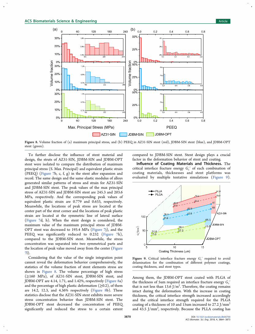
cannot reveal the deformation behavior comprehensively, thestatistics of the volume fraction of stent elements stress areshown in Figure 8. The volume percentage of high stress(≥160 MPa), of AZ31-SIN stent, JDBM-SIN stent, andJDBM-OPT are 4.14, 1.71, and 1.42%, respectively (Figure 8a)and the percentage of high plastic deformation (≥0.2), of themare 14.2, 12.3, and 4.36% respectively (Figure 8b). Thesestatistics disclose that the AZ31-SIN stent exhibits more severestress concentration behavior than JDBM-SIN stent. TheJDBM-OPT stent decreased the concentration of PEEQsignificantly and reduced the stress to a certain extent
compared to JDBM-SIN stent. Stent design plays a crucialfactor in the deformation behavior of stent and coating.
Influence of Coating Materials and Thickness. Thecritical interface fracture energy Gc′ of each combination ofcoating materials, thicknesses and stent platforms wasevaluated by multiple tentative simulations (Figure 9).
Among them, the JDBM-OPT stent coated with PLGA ofthe thickness of 5um required an interface fracture energy Gc′that is not less than 13.6 J/m2. Therefore, the coating remainsintact during the deformation. With the increase in coatingthickness, the critical interface strength increased accordinglyand the critical interface strength required for the PLGAcoating of a thickness of 10 and 15um increased to 27.2 J/mm2
and 43.5 J/mm2, respectively. Because the PLLA coating has
Figure 8. Volume fraction of (a) maximum principal stress, and (b) PEEQ in AZ31-SIN stent (red), JDBM-SIN stent (blue), and JDBM-OPTstent (green).
Figure 9. Critical interface fracture energy Gc′ required to avoiddelamination for the combination of different polymer coatings,coating thickness, and stent types.
ACS Biomaterials Science & Engineering Article
DOI: 10.1021/acsbiomaterials.8b00700ACS Biomater. Sci. Eng. 2018, 4, 3864−3873
3870

higher elastic modulus and yield strength than those of thePLGA coating (2.71 MPa vs 1.58 MPa; 67 MPa vs 29 MPa),the critical interface fracture energy of PLLA is higher than thatof PLGA, based on the same stent platform. In addition, whenthe stent material and design are considered, the analysis of thecritical interface fracture energy Gc′ is consistent with theprevious comparison of the stress distribution statistics (Figure8). Although both the design and the material of the stentaffect the critical interface fracture energy, the primary factor isthe design and the influence of the stent material issubordinate relatively. For example, the critical interfacefracture energies of PLLA with a thickness of 15um on thesestent platforms are 65.3, 87, and 97.9 J/mm2, respectively(Figure 9). The critical interface fracture increased by 33.2%due to the replacement of the stent design while substitutingthe AZ31 for JDBM, the critical interface fracture onlyincreased by 12.3%.
■ DISCUSSIONThe study of stent coating delamination is important becausethe delamination damages the coating integrity and theninfluences the drug delivery adversely.19,21,40 Furthermore, thecoating delamination of biodegradable magnesium alloy stentscan accelerate the localized corrosion of the stent platform.This study applied a 3D finite element model to predict thecoating delamination for three scenarios, and the results arewell-compatible to experimental tests (Figure 5). Consideringthat the FEA framework includes a series of parameters, suchas the material properties of the stent and coating, thethickness of the coating and the interface fracture energy Gc,the validated simulation proved the robustness, accuracy andcompatibility of the proposed CZM framework. As far as theauthors know, this is the first work using a 3D model toevaluate the coating delamination of cardiovascular stents.Compared to the adhesion properties between ChronoFlex
AL and 316L stainless steel captured via peeling test by C.Hopkins et al.,30 our interface fracture energy Gc is muchhigher (58.2 J/m2 vs 29.6 J/m2 for dry sample). The primarycause is that the fluoride acid corrades the sample surface. Theroughness of fluoride magnesium is higher than polishedstainless steel, which leads to higher interface fracture energyGc.
14
The 3D model revealed more information about coatingdelamination which 2D model cannot find, because 3D modelincludes the stent thickness, and stent-balloon contact andfriction. As shown in Figure 6, coating delaminated from theinside edge of strut bow and fractured at the inside edge ofcoating after expansion. This phenomenon is concurrent withthe 2D results.29,31,32 The 3D result shows that the normaltractions at luminal and abluminal location are not the onlyreason for the coating delamination there. The sequence ofstiffness degradation distribution of cohesive elements duringthe initial period of the delamination provided the detailedcohesive elements damaging process (Figure 6f). The contactbetween coating and balloon plays an important factor on thetangential tractions in the initial phase of delamination.Furthermore, these sequences reveal that the debonding isnot instantaneous, but is an incremental process that startsfrom luminal node toward the abluminal location. Thisinference is ignored in the 2D analysis. It is worth notingthat the radial direction is perpendicular to 2D models, whichmeans that the τr will be assumed to be zero in the 2Dsimulation.
Our analyses showed the influence of the material and thedesign of the stent platform on coating delamination. Due tothe higher yield point of AZ31 compared to JDBM (175 MPavs 122 MPa), the plastic strain accumulative zone of the AZ31-SIN stent spreads to the adjacent area slower than JDBM stent,resulting in a smaller plastic deformation zone with a higherplastic deformation peak (Figures 7d, h and 8b). Because ofthe concentrated severe plastic deformation, the straingradients on the surface of the stent bow become sharp andthe interfaces between the coating and the stent have highershear stress, which will accelerate the damaging of cohesiveelements and result in the coating delamination. Furthermore,the local stress concentration of the coating leads to moremicrocracks in the deformed area, which is a potential problemfor the application of the biodegradable magnesium alloystents. Compared with the distinction between the twomagnesium alloys AZ31 and JDBM, the design of stent playsa prominent role in the deformation. The distributions of Max.Principal Stress and PEEQ display completely differentpatterns between OPT and SIN stents (Figure 7j, k). Becauseof the design of the salient contour, the external deformation ofthe OPT stent is spread out to the two shoulders from thecenter area. The gradient width strut contour scattered thedeformation center to the opposite sides (Figure 7k, l). Thepercentage of high plastic deformation of OPT stent is 4.36%(Figure 8b). The numbers confirm that the high plasticdeformation section of the stent decreases sharply when thedeformation concentrated area is dispersed to both sides. Theplastic deformation in the concentration was evenly distributedto vast areas, resulting in the strain gradient on the stentsurface become gentleness, which provides more favorableconditions for the adhesion of the coating.The influence of polymer coating is also important to
control the coating delamination. The analysis of the thicknessand type of polymer coating is concurrent with the previous2D result,29,31 i.e., the thicker the coating, the higher the elasticmodulus and yield strength of the coating, the moreunfavorable the adhesion of the polymer coating on thesurface of the stent. More specifically, PLLA is a semicrystallinepolymer with high rigidity, whereas PLGA is an amorphouspolymer with a soft structure. Mechanical degradation couldoccur because of the deformation and stress concentration,which will accelerate the asymmetric degradation.7,11 PLGAcoating with intact adhesion and low stress distribution is morebeneficial to uniform protection and degradation formagnesium stent, compared to PLLA coating. Moreover,degradation of magnesium matrix could accelerate the drugrelease of PLGA coating to overcome the limitation for furtherclinical application.16 In brief, the stent design that well-matches coating properties can help improve the clinicaloutcome of biodegradable Mg alloy stents.This study has some limitations. First, the zero-thickness
cohesive elements are sensitive to mass scaling in 3D modeling.In our work the target time increment is 2 × 10⁻⁶ s, a largertarget time increment could lead to unstable degradationprocess of the cohesive elements, which means the computa-tional time of 3D simulation is much higher than in a 2Dspace. Second, the balloon is simplified to a cylinder surface.The 3-fold balloon will lead to higher friction force on thecoating surface, especially in the circumferential direction.Third, it can be observed that the gap located in the insideedge of the corner shown in the FEA result (Figure 5b) issmaller than that in the SEM image (Figure 5c). This comes
ACS Biomaterials Science & Engineering Article
DOI: 10.1021/acsbiomaterials.8b00700ACS Biomater. Sci. Eng. 2018, 4, 3864−3873
3871

from the errors introduced during laser-cutting and coatingspray, as well as the asymmetric deformation of crimping andexpansion. Fourth, the property of the polymer coating is indry conditions, considering that the validation experiment iscarried out in vitro without liquid. When a stent is implanted,the material property of PLGA and PLLA will change afterimmersion in blood and the interface strength between coatingand stent will be reduced by hydration. Moreover, the criticalinterface fracture energy Gc′ (Figure 9) is an approximationvalue rather than a precise range, for reducing the amount ofcalculation.
■ CONCLUSIONSThis study provides an easily grasped and intelligibleframework for understanding the deformation of both coatingand stent struts, distinguishing the most important among themultiplying parameters, predicting delamination behavior, andproviding guidelines for stent and coating designers.The significant findings for the polymer coated biodegrad-
able magnesium alloy cardiovascular stents are summarized asfollows:
(1) The debonding process started from luminal locationthen extended to abluminal node, driven by the contactbetween balloon and coating.
(2) JDBM with lower yield strength performed a moreuniform strain and is more favorable for adhesion of thecoating compared to the commercial magnesium alloymade of AZ31.
(3) Shape optimization of the stent improves the strain andstress distribution of the coating observably, avoidingcoating delamination.
(4) PLGA coating with lower elastic modulus and yieldstrength, compared to PLLA polymer, tends to betterfollow the deformation of the stent and to adhere on thesurface tightly.
(5) A reduction in coating thickness and an increase instent-coating interface strength improves the resistanceto delamination.
■ AUTHOR INFORMATIONCorresponding Authors*E-mail: [email protected].*E-mail: [email protected] Chen: 0000-0001-8751-0617Jia Pei: 0000-0002-5256-2895Hua Huang: 0000-0002-2520-8938Guangyin Yuan: 0000-0002-2443-8408Author Contributions†C.C. and J.T. contributed equally to this work.NotesThe authors declare no competing financial interest.
■ ACKNOWLEDGMENTSThe authors acknowledge Dr. Pasquale Vena and Dr. DarioGastaldi for the support in the peeling test. This work wasfinancially supported by the National Key Research andDevelopment Program of China (2016YFC1102103), Scienceand Technology Commission of Shanghai Municipality(17XD1402100, 17DZ2200200), the National Natural Science
Foundation of China (51501115, 51701041), and Politecnicodi Milano International Fellowships Program (PIF).
■ REFERENCES(1) Stefanini, G. G.; Holmes, D. R., Jr. Drug-eluting coronary-arterystents. N. Engl. J. Med. 2013, 368 (3), 254−65.(2) Palmerini, T.; Benedetto, U.; Biondi-Zoccai, G.; Della Riva, D.;Bacchi-Reggiani, L.; Smits, P. C.; Vlachojannis, G. J.; Jensen, L. O.;Christiansen, E. H.; Berencsi, K.; Valgimigli, M.; Orlandi, C.; Petrou,M.; Rapezzi, C.; Stone, G. W. Long-Term Safety of Drug-Eluting andBare-Metal Stents: Evidence From a Comprehensive Network Meta-Analysis. J. Am. Coll. Cardiol. 2015, 65 (23), 2496−507.(3) Im, S. H.; Jung, Y.; Kim, S. H. Current status and futuredirection of biodegradable metallic and polymeric vascular scaffoldsfor next-generation stents. Acta Biomater. 2017, 60, 3−22.(4) Wykrzykowska, J. J.; Kraak, R. P.; Hofma, S. H.; van der Schaaf,R. J.; Arkenbout, E. K.; Ijsselmuiden, A. J.; Elias, J.; van Dongen, I. M.;Tijssen, R. Y. G.; Koch, K. T.; Baan, J., Jr.; Vis, M. M.; de Winter, R.J.; Piek, J. J.; Tijssen, J. G. P.; Henriques, J. P. S. BioresorbableScaffolds versus Metallic Stents in Routine PCI. N. Engl. J. Med. 2017,376 (24), 2319−2328.(5) Ali, Z. A.; Serruys, P. W.; Kimura, T.; Gao, R.; Ellis, S. G.;Kereiakes, D. J.; Onuma, Y.; Simonton, C.; Zhang, Z.; Stone, G. W. 2-year outcomes with the Absorb bioresorbable scaffold for treatment ofcoronary artery disease: a systematic review and meta-analysis ofseven randomised trials with an individual patient data substudy.Lancet 2017, 390 (10096), 760−772.(6) Kereiakes, D. J.; Ellis, S. G.; Metzger, C.; Caputo, R. P.; Rizik, D.G.; Teirstein, P. S.; Litt, M. R.; Kini, A.; Kabour, A.; Marx, S. O.;Popma, J. J.; McGreevy, R.; Zhang, Z.; Simonton, C.; Stone, G. W. 3-Year Clinical Outcomes With Everolimus-Eluting BioresorbableCoronary Scaffolds: The ABSORB III Trial. J. Am. Coll. Cardiol.2017, 70 (23), 2852−2862.(7) Wang, P. J.; Ferralis, N.; Conway, C.; Grossman, J. C.; Edelman,E. R. Strain-induced accelerated asymmetric spatial degradation ofpolymeric vascular scaffolds. Proc. Natl. Acad. Sci. U. S. A. 2018, 115(11), 2640−2645.(8) Mao, L.; Shen, L.; Niu, J.; Zhang, J.; Ding, W.; Wu, Y.; Fan, R.;Yuan, G. Nanophasic biodegradation enhances the durability andbiocompatibility of magnesium alloys for the next-generation vascularstents. Nanoscale 2013, 5 (20), 9517−22.(9) Zheng, Y. F.; Gu, X. N.; Witte, F. Biodegradable metals. Mater.Sci. Eng., R 2014, 77 (0), 1−34.(10) Esmaily, M.; Svensson, J. E.; Fajardo, S.; Birbilis, N.; Frankel, G.S.; Virtanen, S.; Arrabal, R.; Thomas, S.; Johansson, L. G.Fundamentals and advances in magnesium alloy corrosion. Prog.Mater. Sci. 2017, 89, 92−193.(11) Laycock, B.; Nikolic, M.; Colwell, J. M.; Gauthier, E.; Halley,P.; Bottle, S.; George, G. Lifetime prediction of biodegradablepolymers. Prog. Polym. Sci. 2017, 71, 144−189.(12) Haude, M.; Erbel, R.; Erne, P.; Verheye, S.; Degen, H.; Bose,D.; Vermeersch, P.; Wijnbergen, I.; Weissman, N.; Prati, F.;Waksman, R.; Koolen, J. Safety and performance of the drug-elutingabsorbable metal scaffold (DREAMS) in patients with de-novocoronary lesions: 12 month results of the prospective, multicentre,first-in-man BIOSOLVE-I trial. Lancet 2013, 381 (9869), 836−44.(13) Haude, M.; Ince, H.; Abizaid, A.; Toelg, R.; Lemos, P. A.; vonBirgelen, C.; Christiansen, E. H.; Wijns, W.; Neumann, F. J.; Kaiser,C.; Eeckhout, E.; Lim, S. T.; Escaned, J.; Garcia-Garcia, H. M.;Waksman, R. Safety and performance of the second-generation drug-eluting absorbable metal scaffold in patients with de-novo coronaryartery lesions (BIOSOLVE-II): 6 month results of a prospective,multicentre, non-randomised, first-in-man trial. Lancet 2016, 387(10013), 31−9.(14) Jiang, W. S.; Tian, Q. M.; Vuong, T.; Shashaty, M.; Gopez, C.;Sanders, T.; Liu, H. N. Comparison Study on Four BiodegradablePolymer Coatings for Controlling Magnesium Degradation andhuman Endothelial Cell Adhesion and Spreading. ACS Biomater. Sci.Eng. 2017, 3 (6), 936−950.
ACS Biomaterials Science & Engineering Article
DOI: 10.1021/acsbiomaterials.8b00700ACS Biomater. Sci. Eng. 2018, 4, 3864−3873
3872

(15) Liu, J.; Zheng, B.; Wang, P.; Wang, X.; Zhang, B.; Shi, Q.; Xi,T.; Chen, M.; Guan, S. Enhanced in Vitro and in Vivo Performance ofMg-Zn-Y-Nd Alloy Achieved with APTES Pretreatment for Drug-Eluting Vascular Stent Application. ACS Appl. Mater. Interfaces 2016,8 (28), 17842−58.(16) Shi, Y. J.; Pei, J.; Zhang, L.; Lee, B. K.; Yun, Y.; Zhang, J.; Li, Z.H.; Gu, S.; Park, K.; Yuan, G. Y. Understanding the effect ofmagnesium degradation on drug release and anti-proliferation onsmooth muscle cells for magnesium-based drug eluting stents. Corros.Sci. 2017, 123, 297−309.(17) Shi, Y.; Zhang, L.; Chen, J.; Zhang, J.; Yuan, F.; Shen, L.; Chen,C.; Pei, J.; Li, Z.; Tan, J.; Yuan, G. In vitro and in vivo degradation ofrapamycin-eluting Mg-Nd-Zn-Zr alloy stents in porcine coronaryarteries. Mater. Sci. Eng., C 2017, 80, 1−6.(18) Ng, J.; Foin, N.; Ang, H. Y.; Fam, J. M.; Sen, S.; Nijjer, S.;Petraco, R.; Di Mario, C.; Davies, J.; Wong, P. Over-expansioncapacity and stent design model: An update with contemporary DESplatforms. Int. J. Cardiol. 2016, 221, 171−9.(19) Watanabe, T.; Fujita, M.; Awata, M.; Iida, O.; Okamoto, S.;Ishihara, T.; Uematsu, M. Integrity of stent polymer layer after drug-eluting stent implantation: in vivo comparison of sirolimus-,paclitaxel-, zotarolimus- and everolimus-eluting stents. Cardiovasc.Intervention Ther. 2014, 29 (1), 4−10.(20) Levy, Y.; Mandler, D.; Weinberger, J.; Domb, A. J. Evaluationof drug-eluting stents’ coating durability–clinical and regulatoryimplications. J. Biomed. Mater. Res., Part B 2009, 91 (1), 441−451.(21) Karanasiou, G. S.; Papafaklis, M. I.; Conway, C.; Michalis, L.K.; Tzafriri, R.; Edelman, E. R.; Fotiadis, D. I. Stents: Biomechanics,Biomaterials, and Insights from Computational Modeling. Ann.Biomed. Eng. 2017, 45 (4), 853−872.(22) McHugh, P.; Barakat, A.; McGinty, S. Medical Stents: State ofthe Art and Future Directions. Ann. Biomed. Eng. 2016, 44 (2), 274−5.(23) Bressloff, N. W.; Ragkousis, G.; Curzen, N. DesignOptimisation of Coronary Artery Stent Systems. Ann. Biomed. Eng.2016, 44 (2), 357−67.(24) Grogan, J. A.; Leen, S. B.; McHugh, P. E. Optimizing the designof a bioabsorbable metal stent using computer simulation methods.Biomaterials 2013, 34 (33), 8049−60.(25) Wu, W.; Petrini, L.; Gastaldi, D.; Villa, T.; Vedani, M.; Lesma,E.; Previtali, B.; Migliavacca, F. Finite element shape optimization forbiodegradable magnesium alloy stents. Ann. Biomed. Eng. 2010, 38(9), 2829−40.(26) Wu, W.; Chen, S.; Gastaldi, D.; Petrini, L.; Mantovani, D.;Yang, K.; Tan, L.; Migliavacca, F. Experimental data confirmnumerical modeling of the degradation process of magnesium alloysstents. Acta Biomater. 2013, 9 (10), 8730−9.(27) Gu, Z.; Li, S.; Zhang, F.; Wang, S. Understanding SurfaceAdhesion in Nature: A Peeling Model. Adv. Sci. (Weinh) 2016, 3 (7),1500327.(28) Diehl, T. On using a penalty-based cohesive-zone finite elementapproach, Part I: Elastic solution benchmarks. Int. J. Adhes. Adhes.2008, 28 (4−5), 237−255.(29) Hopkins, C. G.; McHugh, P. E.; McGarry, J. P. Computationalinvestigation of the delamination of polymer coatings during stentdeployment. Ann. Biomed. Eng. 2010, 38 (7), 2263−73.(30) Hopkins, C.; McHugh, P. E.; O’Dowd, N. P.; Rochev, Y.;McGarry, J. P. A combined computational and experimentalmethodology to determine the adhesion properties of stent polymercoatings. Comput. Mater. Sci. 2013, 80, 104−112.(31) Hopkins, C.; Sweeney, C. A.; O’Connor, C.; McHugh, P. E.;McGarry, J. P. Webbing and Delamination of Drug Eluting StentCoatings. Ann. Biomed. Eng. 2016, 44 (2), 419−31.(32) Wu, W.; Mercuri, M.; Pedroni, C.; Migliavacca, F.; Petrini, L. AComputational Study to Investigate Debonding in Coated Bioresorb-able Stents. J. Mech. Med. Biol. 2015, 15 (2), 1540015.(33) Zhang, J.; Kong, N.; Shi, Y.; Niu, J.; Mao, L.; Li, H.; Xiong, M.;Yuan, G. Influence of proteins and cells on in vitro corrosion of Mg−Nd−Zn−Zr alloy. Corros. Sci. 2014, 85 (0), 477−481.
(34) Liu, F.; Chen, C.; Niu, J.; Pei, J.; Zhang, H.; Huang, H.; Yuan,G. The processing of Mg alloy micro-tubes for biodegradable vascularstents. Mater. Sci. Eng., C 2015, 48, 400−7.(35) Zhang, J.; Li, H.; Wang, W.; Huang, H.; Pei, J.; Qu, H.; Yuan,G.; Li, Y. The degradation and transport mechanism of a Mg-Nd-Zn-Zr stent in rabbit common carotid artery: A 20-month study. ActaBiomater. 2018, 69, 372−384.(36) Paryab, N.; Cronin, D.; Lee-Sullivan, P.; Ying, X.; Boey, F. Y.C.; Venkatraman, S. Uniform Expansion of a Polymeric Helical Stent.J. Med. Devices 2012, 6 (2), 021012.(37) De Falco, P.; Barbieri, E.; Pugno, N.; Gupta, H. S. StaggeredFibrils and Damageable Interfaces Lead Concurrently and Independ-ently to Hysteretic Energy Absorption and Inhomogeneous StrainFields in Cyclically Loaded Antler Bone. ACS Biomater. Sci. Eng. 2017,3 (11), 2779−2787.(38) Wei, W.; Petrini, L.; Altomare, L.; Fare, S.; Tremamunno, R.;Yu, Z.; Migliavacca, F. Modeling and Experimental Studies of Peelingof Polymer Coating for Biodegradable Magnesium Alloy Stents. RareMet. Mater. Eng. 2014, 43 (12), 2877−2882.(39) Lucchini, R.; Cattarinuzzi, E.; Maraghechi, S.; Gastaldi, D.;Adami, A.; Lorenzelli, L.; Vena, P. Delamination phenomena inaluminum/polyimide deformable interconnects: In-situ micro-tensiletesting. Mater. Des. 2016, 89, 121−128.(40) Gu, X.; Mao, Z.; Ye, S. H.; Koo, Y.; Yun, Y.; Tiasha, T. R.;Shanov, V.; Wagner, W. R. Biodegradable, elastomeric coatings withcontrolled anti-proliferative agent release for magnesium-basedcardiovascular stents. Colloids Surf., B 2016, 144, 170−179.
ACS Biomaterials Science & Engineering Article
DOI: 10.1021/acsbiomaterials.8b00700ACS Biomater. Sci. Eng. 2018, 4, 3864−3873
3873