MODEL W1745W 6 JOINTER W/MOBILE BASE
64
OWNER'S MANUAL (FOR MODELS MANUFACTURED SINCE 9/15) MODEL W1745W 6" JOINTER W /MOBILE BASE Phone: (360) 734-3482 • Online Technical Support: [email protected] COPYRIGHT © February, 2016 BY WOODSTOCK INTERNATIONAL, INC. WARNING: NO PORTION OF THIS MANUAL MAY BE REPRODUCED IN ANY SHAPE OR FORM WITHOUT THE WRITTEN APPROVAL OF WOODSTOCK INTERNATIONAL, INC. #17784JH Printed in China
Transcript of MODEL W1745W 6 JOINTER W/MOBILE BASE

OWNER'S MANUAL(FOR MODELS MANUFACTURED SINCE 9/15)
MODEL W1745W6" JOINTER
W/MOBILE BASE
Phone: (360) 734-3482 • Online Technical Support: [email protected]
COPYRIGHT © February, 2016 BY WOODSTOCK INTERNATIONAL, INC.WARNING: NO PORTION OF THIS MANUAL MAY BE REPRODUCED IN ANY SHAPE OR FORM WITHOUT
THE WRITTEN APPROVAL OF WOODSTOCK INTERNATIONAL, INC.#17784JH Printed in China

This manual provides critical safety instructions on the proper setup, operation, maintenance, and service of this machine/tool. Save this document, refer to it often, and use it to instruct other operators.
Failure to read, understand and follow the instructions in this manual may result in fire or serious personal injury—including amputation, electrocution, or death.
The owner of this machine/tool is solely responsible for its safe use. This responsibility includes but is not limited to proper installation in a safe environment, personnel training and usage authorization, proper inspection and maintenance, manual availability and compre-hension, application of safety devices, cutting/sanding/grinding tool integrity, and the usage of personal protective equipment.
The manufacturer will not be held liable for injury or property damage from negligence, improper training, machine modifications or misuse.
Some dust created by power sanding, sawing, grinding, drilling, and other construction activities contains chemicals known to the State of California to cause cancer, birth defects or other reproductive harm. Some examples of these chemicals are:
• Lead from lead-based paints.• Crystalline silica from bricks, cement and other masonry products.• Arsenic and chromium from chemically-treated lumber.
Your risk from these exposures varies, depending on how often you do this type of work. To reduce your exposure to these chemicals: Work in a well ventilated area, and work with approved safety equip-ment, such as those dust masks that are specially designed to filter out microscopic particles.
SET UP
ELECTRICAL
MA
INTEN
AN
CESERVICE
OPER
ATION
SSA
FETY
INTRO
DUCTIO
N
USE THE QUICK GUIDE PAGE LABELS TO SEARCH OUT INFORMATION FAST!
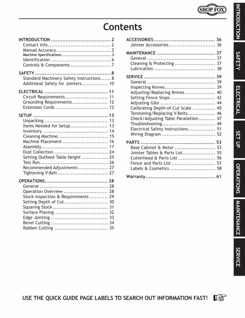
INTRODUCTION......................................2Contact Info ....................................... 2Manual Accuracy .................................. 2Machine Specifications .....................................3Identification ..................................... 6Controls & Components ......................... 7
SAFETY................................................8Standard Machinery Safety Instructions ...... 8Additional Safety for Jointers ................ 10
ELECTRICAL........................................ 11Circuit Requirements .......................... 11Grounding Requirements ...................... 12Extension Cords ................................ 12
SETUP............................................... 13Unpacking ....................................... 13Items Needed for Setup ....................... 13Inventory ........................................ 14Cleaning Machine ............................... 15Machine Placement ............................ 16Assembly ......................................... 17Dust Collection ................................. 24Setting Outfeed Table Height ................ 25Test Run .......................................... 26Recommended Adjustments .................. 27Tightening V-Belt ............................... 27
OPERATIONS....................................... 28General .......................................... 28Operation Overview ........................... 28Stock Inspection & Requirements ........... 29Setting Depth of Cut ........................... 30Squaring Stock .................................. 31Surface Planing ................................. 32Edge Jointing ................................... 33Bevel Cutting ................................... 34Rabbet Cutting ................................. 35
ACCESSORIES....................................... 36Jointer Accessories ............................. 36
MAINTENANCE..................................... 37General .......................................... 37Cleaning & Protecting ......................... 37Lubrication ...................................... 38
SERVICE............................................. 39General .......................................... 39Inspecting Knives ............................... 39Adjusting/Replacing Knives ................... 40Setting Fence Stops ............................ 42Adjusting Gibs .................................. 44Calibrating Depth-of-Cut Scale .............. 45Tensioning/Replacing V-Belts ................. 46Check/Adjusting Table Parallelism .......... 47Troubleshooting ................................. 49Electrical Safety Instructions ................. 51Wiring Diagram ................................. 52
PARTS............................................... 53Base Cabinet & Motor ......................... 53Jointer Tables & Parts List .................... 55Cutterhead & Parts List ....................... 56Fence and Parts List ........................... 57Labels & Cosmetics ............................ 58
Warranty............................................ 61
Contents

-2-
Model W1745W (For Machines Mfd. Since 9/15)IN
TRO
DUCT
ION
INTRODUCTION
We are proud to provide a high-quality owner’s manual with your new machine!
We made every effort to be exact with the instructions, specifications, drawings, and pho-tographs contained inside. Sometimes we make mistakes, but our policy of continuous improve-ment also means that sometimes. the.machine.you.receive.will.be.slightly.different.than.what.is.shown.in.the.manual.
If you find this to be the case, and the difference between the manual and machine leaves you confused about a procedure, check our website for an updated version. We post current manuals and manual updates for free on our website at www.woodstockint.com.
Alternatively, you can call our Technical Support for help. Before calling, make sure you write down the Manufacture.Date and Serial.Number from the machine ID label (see below). Also, if available, have a copy of your original.purchase.receipt on hand. This information is required for all Tech Support calls.
MODEL XXXXMACHINE NAME
Motor:Specification: Specification:Specification:Specification:Weight:
SpecificationsTo reduce risk of serious personal injury when using this machine: 1. Read & understand owner’s manual before operating. 2. Always wear approved eye protection and respirator. 3. Only plug power cord into a grounded outlet. 4. Only use this machine to collect wood dust/chips—never
use to collect glass, metal, liquids, asbestos, silica, animal parts, biohazards, burning material/ashes, etc.
5. Always disconnect power before servicing or cleaning. 6. Do not expose to rain or wet areas. 7. Keep hands, long hair, and loose clothing away from
inlet. 8. Never leave machine unattended while it is running. 9. Do not use if cord/plug becomes damaged—promptly
repair and protect cord from future damage. 10. Do not use without dust bag or filters in place. 11. Always wear a respirator when emptying bags. 12. Prevent unauthorized use by children or untrained users.
Date
Serial Number
Manufactured for Woodstock in Taiwan
WARNING!
Manufacture Date
Serial Number
Manual.AccuracyWe are committed to customer satisfaction. If you have any questions or need help, use the information below to contact us.
IMPORTANT:.Before.contacting,.please.get.the.original.purchase.receipt,.serial.number,.and.manufacture.date.of.your.machine..This.infor-mation. is. required. for. all. Technical. Support.calls.and.it.will.help.us.help.you.faster..
Woodstock International Technical SupportPhone: (360) 734-3482
Email: [email protected]
We want your feedback on this manual. What did you like about it? Where could it be improved? Please take a few minutes to give us feedback.
Technical Documentation ManagerP.O. Box 2309
Bellingham, WA 98227Email: [email protected]
Contact.Info
-3-
Model W1745W (For Machines Mfd. Since 9/15)IN
TRODU
CTION
Machine Specifications
Model W1745W Machine Specifications, Page 1 of 3
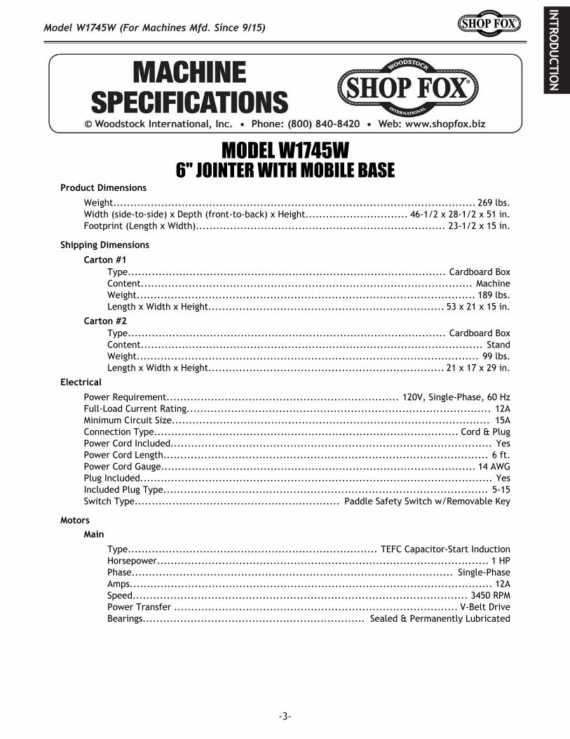
MODEL W1745W6" JOINTER WITH MOBILE BASE
Product Dimensions
Weight.......................................................................................................... 269 lbs.Width (side‐to‐side) x Depth (front‐to‐back) x Height.............................. 46‐1/2 x 28‐1/2 x 51 in.Footprint (Length x Width)......................................................................... 23‐1/2 x 15 in.
Shipping Dimensions
Carton #1Type............................................................................................. Cardboard BoxContent................................................................................................. MachineWeight................................................................................................... 189 lbs.Length x Width x Height..................................................................... 53 x 21 x 15 in.
Carton #2Type............................................................................................. Cardboard BoxContent.................................................................................................... StandWeight.................................................................................................... 99 lbs.Length x Width x Height..................................................................... 21 x 17 x 29 in.
Electrical
Power Requirement.................................................................... 120V, Single‐Phase, 60 HzFull‐Load Current Rating......................................................................................... 12AMinimum Circuit Size............................................................................................. 15AConnection Type......................................................................................... Cord & PlugPower Cord Included.............................................................................................. YesPower Cord Length............................................................................................... 6 ft.Power Cord Gauge............................................................................................ 14 AWGPlug Included....................................................................................................... YesIncluded Plug Type............................................................................................... 5‐15Switch Type............................................................ Paddle Safety Switch w/Removable Key
MotorsMain
Type......................................................................... TEFC Capacitor‐Start InductionHorsepower................................................................................................. 1 HPPhase.............................................................................................. Single‐PhaseAmps.......................................................................................................... 12ASpeed.................................................................................................. 3450 RPMPower Transfer ................................................................................... V‐Belt DriveBearings................................................................. Sealed & Permanently Lubricated

-4-
Model W1745W (For Machines Mfd. Since 9/15)IN
TRO
DUCT
ION
Model W1745W Machine Specifications, Page 2 of 3
Main Specifications
Main Specifications
Bevel Jointing................................................................................. 0 – 45 deg. L/RMaximum Width of Cut................................................................................... 6 in.Maximum Depth of Cut................................................................................ 1/8 in.Minimum Workpiece Length............................................................................. 8 in.Minimum Workpiece Thickness....................................................................... 1/2 in.Maximum Rabbeting Depth............................................................................ 1/2 in.Number of Cuts Per Minute............................................................................ 14,700
Fence Information
Fence Length............................................................................................. 35 in.Fence Width........................................................................................... 1‐1/2 in.Fence Height............................................................................................... 5 in.Fence Stops.................................................................................. 45, 90, 135 deg.
Cutterhead Information
Cutterhead Type........................................................................................ 3 KnifeCutterhead Diameter................................................................................ 2‐1/2 in.Cutterhead Speed................................................................................... 4900 RPM
Knife Information
Number of Knives.............................................................................................. 3Knife Type................................................................................... HSS, Single‐SidedKnife Length................................................................................................ 6 in.Knife Width.............................................................................................. 3/4 in.Knife Thickness......................................................................................... 1/8 in.Knife Adjustment................................................................................. Jack Screws
Table Information
Table Length......................................................................................... 46‐1/2 in.Table Width........................................................................................... 7‐1/2 in.Table Thickness............................................................................. 1‐1/8 – 3‐3/8 in.Floor to Table Height.............................................................................. 32‐1/2 in.Table Adjustment Type................................................................... Handwheel/LeverTable Movement Type...................................................................... Dovetailed Ways
Construction
Body Assembly........................................................................................ Cast IronCabinet..................................................................................................... SteelFence Assembly....................................................................................... Cast IronGuard............................................................................................ Die Cast MetalTable............................................................................. Precision‐Ground Cast IronPaint Type/Finish............................................................................. Powder Coated
Other Information
Number of Dust Ports......................................................................................... 1Dust Port Size.............................................................................................. 4 in.Mobile Base............................................................................................. Built‐In

-5-
Model W1745W (For Machines Mfd. Since 9/15)IN
TRODU
CTION
Model W1745W Machine Specifications, Page 3 of 3
Other
Country of Origin ............................................................................................... ChinaWarranty ....................................................................................................... 2 YearsApproximate Assembly & Setup Time ...................................................................... 1 HourSerial Number Location .................................................................................... ID LabelISO 9001 Factory ................................................................................................... NoCertified by a Nationally Recognized Testing Laboratory (NRTL) .......................................... No
Features
Beds Slide on Dovetailed WaysCenter‐Mounted Fence with Positive Stops at 45, 90 and 135 DegreesHandwheel‐Adjusted Outfeed Table, Lever‐Adjusted Infeed Table w/Depth GaugePedestal‐Mounted, Easy‐Access Switch with Removable Safety KeyBuilt‐in Mobile BaseBuilt‐in Dust Chute with 4" Collection HoodRack and Pinion Fence AdjustmentIncludes Free Pair of Safety Push Blocks and Knife‐Setting JigV‐Belt Drive3‐Knife CutterheadPrecision‐Ground Cast‐Iron Tables and FenceRabbeting Table

-6-
Model W1745W (For Machines Mfd. Since 9/15)IN
TRO
DUCT
ION
Identification
A. Outfeed TableB. FenceC. Cutterhead GuardD. Fence Tilt HandleE. Fence LockF. Fence Adjustment KnobG. Control Panel
H. Infeed TableI. Infeed Table Adjustment LeverJ. Depth ScaleK. Locking Foot PedalL. Dust PortM. Outfeed Table Handwheel
Become familiar with the names and locations of the controls and features shown below to better understand the instructions in this manual.
For Your Own Safety Read Instruction Manual Before Operating Jointera) Wear eye protection.b) Always keep cutterhead and drive guards in place and in proper operating condition. ALWAYS
replace cutterhead guard after rabbeting operations.c) Never make jointing or rabbeting cuts deeper than 1⁄8" or planing cuts deeper than 1⁄16"d) Always use hold-down or push blocks when jointing material narrower than 3" or surface
planing material thinner than 3".e) Never perform jointing, planing, or rabbeting cuts on pieces shorter than 8" in length.
A
C
FD G
H
I
J
K
BE
M
L
-7-
Model W1745W (For Machines Mfd. Since 9/15)IN
TRODU
CTION
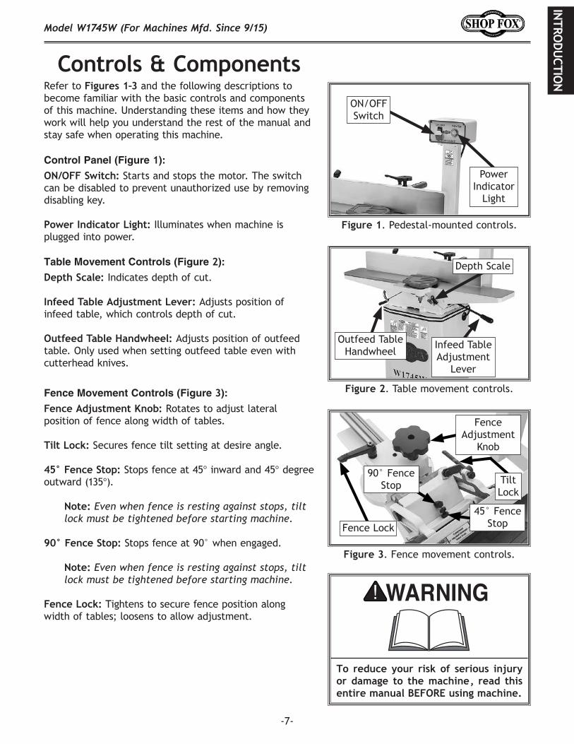
Controls.&.ComponentsRefer to Figures 1–3 and the following descriptions to become familiar with the basic controls and components of this machine. Understanding these items and how they work will help you understand the rest of the manual and stay safe when operating this machine.
Control Panel (Figure 1):
ON/OFF Switch: Starts and stops the motor. The switch can be disabled to prevent unauthorized use by removing disabling key.
Power Indicator Light: Illuminates when machine is plugged into power.
To. reduce. your. risk. of. serious. injury.or. damage. to. the. machine,. read. this.entire.manual.BEFORE.using.machine.
Table Movement Controls (Figure 2):
Depth Scale: Indicates depth of cut.
Infeed Table Adjustment Lever: Adjusts position of infeed table, which controls depth of cut.
Outfeed Table Handwheel: Adjusts position of outfeed table. Only used when setting outfeed table even with cutterhead knives.
Fence Movement Controls (Figure 3):
Fence Adjustment Knob: Rotates to adjust lateral position of fence along width of tables.
Tilt Lock: Secures fence tilt setting at desire angle.
45° Fence Stop: Stops fence at 45° inward and 45° degree outward (135°).
Note: Even when fence is resting against stops, tilt lock must be tightened before starting machine.
90° Fence Stop: Stops fence at 90° when engaged.
Note: Even when fence is resting against stops, tilt lock must be tightened before starting machine.
Fence Lock: Tightens to secure fence position along width of tables; loosens to allow adjustment.
Figure 3. Fence movement controls.
Figure 1. Pedestal-mounted controls.
Power Indicator
Light
ON/OFF Switch
Figure 2. Table movement controls.
Infeed TableAdjustment
Lever
Outfeed TableHandwheel
Depth Scale
Fence Lock
Fence Adjustment
Knob
45° Fence Stop
90° Fence Stop Tilt
Lock

-8-
Model W1745W (For Machines Mfd. Since 9/15)SA
FET
Y
Indicates.a.potentially.hazardous.situation.which,.if.not.avoided,.MAY.result.in.minor.or.moderate.injury.
Indicates.an.imminently.hazardous.situation.which,.if.not.avoided,.WILL.result.in.death.or.serious.injury.
Indicates.a.potentially.hazardous.situation.which,.if.not.avoided,.COULD.result.in.death.or.serious.injury.
This.symbol.is.used.to.alert.the.user.to.useful.information.about.proper.operation.of.the.equipment.or.a.situation.that.may.cause.damage.to.the.machinery.
NOTICE
SAFETY
OWNER’S.MANUAL..Read and understand this owner’s manual BEFORE using machine.
TRAINED.OPERATORS.ONLY..Untrained operators have a higher risk of being hurt or killed. Only allow trained/supervised people to use this machine. When machine is not being used, disconnect power, remove switch keys, or lock-out machine to prevent unauthorized use—especially around children. Make workshop kid proof!
DANGEROUS.ENVIRONMENTS..Do not use machinery in areas that are wet, cluttered, or have poor lighting. Operating machinery in these areas greatly increases the risk of accidents and injury.
MENTAL.ALERTNESS.REQUIRED..Full mental alertness is required for safe operation of machinery. Never operate under the influence of drugs or alcohol, when tired, or when distracted.
ELECTRICAL.EQUIPMENT.INJURY.RISKS..You can be shocked, burned, or killed by touching live electrical components or improperly grounded machinery. To reduce this risk, only allow an electrician or qualified service personnel to do electrical installation or repair work, and always disconnect power before accessing or exposing electrical equipment.
DISCONNECT.POWER.FIRST..Always disconnect machine from power supply BEFORE making adjustments, changing tooling, or servicing machine. This eliminates the risk of injury from unintended startup or contact with live electrical components.
EYE.PROTECTION..Always wear ANSI-approved safety glasses or a face shield when operating or observing machinery to reduce the risk of eye injury or blindness from flying particles. Everyday eyeglasses are not approved safety glasses.
Standard.Machinery.Safety.Instructions
For.Your.Own.Safety,Read.Manual.Before.Operating.Machine
The. purpose. of. safety. symbols. is. to. attract. your. attention. to. possible. hazardous. conditions.. This.manual.uses.a.series.of.symbols.and.signal.words.intended.to.convey.the.level.of.importance.of.the.safety.messages..The.progression.of.symbols.is.described.below..Remember.that.safety.messages.by.themselves.do.not.eliminate.danger.and.are.not.a.substitute. for.proper.accident.prevention.mea-sures—this.responsibility.is.ultimately.up.to.the.operator!
SAFETY
Standard Machinery Safety Instructions
-9-
Model W1745W (For Machines Mfd. Since 9/15)SA
FETY
WEARING.PROPER.APPAREL..Do not wear clothing, apparel, or jewelry that can become entangled in moving parts. Always tie back or cover long hair. Wear non-slip footwear to avoid accidental slips, which could cause loss of workpiece control.
HAZARDOUS.DUST..Dust created while using machinery may cause cancer, birth defects, or long-term respiratory damage. Be aware of dust hazards associated with each workpiece material, and always wear a NIOSH-approved respirator to reduce your risk.
HEARING.PROTECTION..Always wear hearing protection when operating or observing loud machinery. Extended exposure to this noise without hearing protection can cause permanent hearing loss.
REMOVE.ADJUSTING.TOOLS..Tools left on machinery can become dangerous projectiles upon startup. Never leave chuck keys, wrenches, or any other tools on machine. Always verify removal before starting!
INTENDED.USAGE..Only use machine for its intended purpose—never make modifications without prior approval from Woodstock International. Modifying machine or using it differently than intended will void the warranty and may result in malfunction or mechanical failure that leads to serious personal injury or death!
AWKWARD.POSITIONS..Keep proper footing and balance at all times when operating machine. Do not overreach! Avoid awkward hand positions that make workpiece control difficult or increase the risk of accidental injury.
CHILDREN.&.BYSTANDERS..Keep children and bystanders at a safe distance from the work area. Stop using machine if they become a distraction.
GUARDS.&.COVERS..Guards and covers reduce accidental contact with moving parts or flying debris—make sure they are properly installed, undamaged, and working correctly.
FORCING.MACHINERY..Do not force machine. It will do the job safer and better at the rate for which it was designed.
NEVER.STAND.ON.MACHINE..Serious injury may occur if machine is tipped or if the cutting tool is unintentionally contacted.
STABLE.MACHINE..Unexpected movement during operation greatly increases risk of injury or loss of control. Before starting, verify machine is stable and mobile base (if used) is locked.
USE.RECOMMENDED.ACCESSORIES..Consult this owner’s manual or the manufacturer for recommended accessories. Using improper accessories will increase risk of serious injury.
UNATTENDED.OPERATION..To reduce the risk of accidental injury, turn machine OFF and ensure all moving parts completely stop before walking away. Never leave machine running while unattended.
MAINTAIN.WITH.CARE..Follow all maintenance instructions and lubrication schedules to keep machine in good working condition. A machine that is improperly maintained could malfunction, leading to serious personal injury or death.
CHECK.DAMAGED.PARTS..Regularly inspect machine for any condition that may affect safe operation. Immediately repair or replace damaged or mis-adjusted parts before operating machine.
MAINTAIN.POWER.CORDS..When disconnecting cord-connected machines from power, grab and pull the plug—NOT the cord. Pulling the cord may damage the wires inside, resulting in a short. Do not handle cord/plug with wet hands. Avoid cord damage by keeping it away from heated surfaces, high traffic areas, harsh chemicals, and wet/damp locations.
EXPERIENCING.DIFFICULTIES..If at any time you experience difficulties performing the intended operation, stop using the machine! Contact Technical Support at (360) 734-3482.
-10-
Model W1745W (For Machines Mfd. Since 9/15)SA
FET
Y
Additional.Safety.for.JointersSerious cuts, amputation, entanglement, or death can occur from contact with rotating cutterhead or other moving components! Flying chips can cause blindness or eye injuries. Workpieces or inserts/knives thrown by cutterhead can strike nearby operator or bystanders with deadly force. To reduce risk, operator and bystanders MUST completely heed hazards and warnings below.
GRAIN DIRECTION. Jointing against the grain or end grain can increase the risk of kickback. It also requires more cutting force, which pro-duces chatter or excessive chip out. Always joint or surface plane WITH the grain.
CUTTING LIMITATIONS. Cutting a workpiece that does not meet the minimum dimension requirements can result in breakup, kickback, or accidental contact with cutterhead during operation. Never perform jointing, planing, or rabbeting cuts on pieces smaller than 8" long, 3⁄4" wide, or 1⁄4" thick.
PUSH BLOCKS. Not using push blocks when surface planing may result in accidental cutterhead contact. Always use push blocks when planing materials less than 3" high or wide. Never pass your hands directly over cutterhead without a push block.
WORKPIECE SUPPORT. Loss of workpiece con-trol while feeding can increase risk of kick-back or accidental contact with cutterhead. Support workpiece continuously during opera-tion. Support long or wide stock with auxiliary stands.
FEED WORKPIECE PROPERLY. Kickback or acciden-tal cutterhead contact may result if workpiece is fed into cutterhead the wrong way. Allow cutterhead to reach full speed before feed-ing. Never start jointer with workpiece touch-ing cutterhead. Always feed workpiece from infeed side to outfeed side without stopping until cut is complete. Never back work toward infeed table.
SECURE KNIVES/INSERTS. Loose knives or improp-erly set inserts can become dangerous projec-tiles or cause machine damage. Always verify knives/inserts are secure and properly adjust-ed before operation. Straight knives should never project more than 1⁄8" (0.125") from cutterhead body.
KICKBACK. Occurs when workpiece is ejected from machine at a high rate of speed. To reduce the risk of kickback-related inju-ries, use quality workpieces, safe feeding techniques, and proper machine setup or maintenance.
GUARD REMOVAL. Operating jointer without guard exposes operator to knives/inserts. Except when rabbeting, never remove guards for regular operations or while con-nected to power. Turn jointer OFF and disconnect power before clearing any shav-ings or sawdust from around cutterhead. After rabbeting or maintenance is complete, immediately replace all guards and ensure they are properly adjusted before resuming regular operations.
DULL/DAMAGED KNIVES/INSERTS. Dull knives/inserts can increase risk of kickback and cause poor workpiece finish. Only use sharp, undamaged knives/inserts.
OUTFEED TABLE ALIGNMENT. Setting outfeed table too high can cause workpiece to hit table and get stuck, increasing risk of kick-back. Setting outfeed table too low may cause workpiece to become tapered from front to back. Always keep outfeed table even with knives/inserts at highest point during rotation.
INSPECTING STOCK. Impact injuries or fire may result from using poor workpieces. Thoroughly inspect and prepare workpiece before cutting. Verify workpiece is free of nails, staples, loose knots or other foreign material. Workpieces with minor warping should be surface planed first with cupped side facing infeed table.
MAXIMUM CUTTING DEPTH. To reduce risk of kickback, never cut deeper than 1⁄8” per pass.
-11-
Model W1745W (For Machines Mfd. Since 9/15)ELECTRICA
L
ELECTRICALCircuit Requirements
This machine must be connected to the correct size and type of power supply circuit, or fire or electrical damage may occur. Read through this section to determine if an adequate power supply circuit is available. If a correct circuit is not available, a qualified electrician MUST install one before you can connect the machine to power.
A power supply circuit includes all electrical equipment between the breaker box or fuse panel in the building and the machine. The power supply circuit used for this machine must be sized to safely handle the full-load current drawn from the machine for an extended period of time. (If this machine is connected to a circuit protected by fuses, use a time delay fuse marked D.)
Circuit Requirements for 110VThis machine is prewired to operate on a power supply circuit that has a verified ground and meets the following requirements:
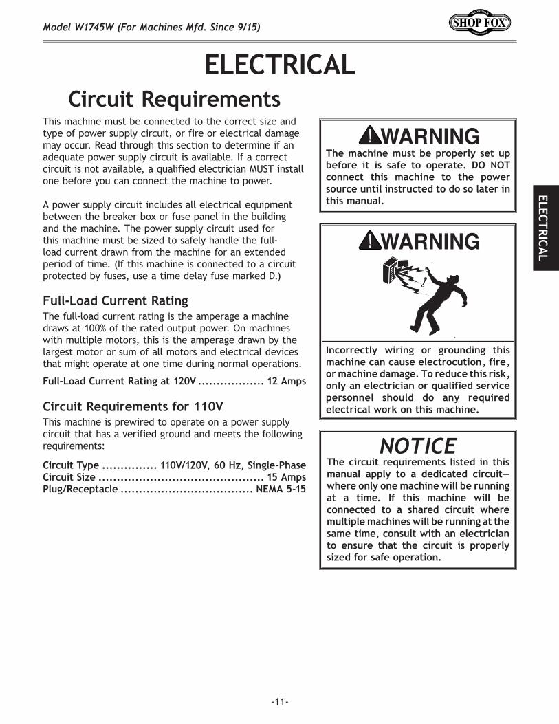
Circuit Type ............... 110V/120V, 60 Hz, Single-PhaseCircuit Size ............................................. 15 AmpsPlug/Receptacle .................................... NEMA 5-15
Full-Load Current RatingThe full-load current rating is the amperage a machine draws at 100% of the rated output power. On machines with multiple motors, this is the amperage drawn by the largest motor or sum of all motors and electrical devices that might operate at one time during normal operations.
Full-Load Current Rating at 120V .................. 12 Amps
The.machine.must.be.properly. set.up.before. it. is. safe. to. operate.. DO. NOT.connect. this. machine. to. the. power.source.until.instructed.to.do.so.later.in.this.manual.
Incorrectly. wiring. or. grounding. this.machine.can.cause.electrocution,.fire,.or.machine.damage..To.reduce.this.risk,.only.an.electrician.or.qualified.service.personnel. should. do. any. required.electrical.work.on.this.machine.
NOTICE The.circuit. requirements. listed. in. this.manual. apply. to. a. dedicated. circuit—where.only.one.machine.will.be.running.at. a. time.. If. this. machine. will. be.connected. to. a. shared. circuit. where.multiple.machines.will.be.running.at.the.same.time,.consult.with.an.electrician.to. ensure. that. the. circuit. is. properly.sized.for.safe.operation.

-12-
Model W1745W (For Machines Mfd. Since 9/15)EL
ECTR
ICA
L
Grounding RequirementsThis machine MUST be grounded. In the event of certain types of malfunctions or breakdowns, grounding provides a path of least resistance for electric current to travel—in order to reduce the risk of electric shock.
Improper connection of the equipment-grounding wire will increase the risk of electric shock. The wire with green insulation (with/without yellow stripes) is the equipment-grounding wire. If repair or replacement of the power cord or plug is necessary, do not connect the equipment-grounding wire to a live (current carrying) terminal. Check with a qualified electrician or service personnel if you do not understand these grounding requirements, or if you are in doubt about whether the tool is properly grounded. If you ever notice that a cord or plug is damaged or worn, disconnect it from power, and immediately replace it with a new one.
Grounding Prong
Neutral Hot5-15 PLUG
GROUNDED5-15 RECEPTACLE110V
Figure 4. NEMA 5-15 plug & receptacle.
DO. NOT. modify. the. provided. plug. or.use. an. adapter. if. the. plug. will. not.fit. the. receptacle.. Instead,. have. an.electrician.install.the.proper.receptacle.on. a. power. supply. circuit. that. meets.the.requirements.for.this.machine.
Extension CordsWe do not recommend using an extension cord with this machine. Extension cords cause voltage drop, which may damage electrical components and shorten motor life. Voltage drop increases with longer extension cords and smaller gauge sizes (higher gauge numbers indicate smaller sizes).
Any extension cord used with this machine must contain a ground wire, match the required plug and receptacle, and meet the following requirements:
Minimum Gauge Size at 110V ...................... 14 AWGMaximum Length (Shorter is Better).................50 ft.
For 110V Connection This machine is equipped with a power cord that has an equipment-grounding wire and NEMA 5-15 grounding plug. The plug must only be inserted into a matching receptacle (see Figure) that is properly installed and grounded in accordance with local codes and ordinances.

-13-
Model W1745W (For Machines Mfd. Since 9/15)SETU
P
SUFFOCATION HAZARD!Immediately discard all plastic bags and packing materials to eliminate c h o k i n g / s u f f o c a t i o n hazards for children and animals.
SETUP
Description Qty• Additional People ..........................................2• Straightedge 4' .............................................1• Safety Glasses ................................1 Per Person• Dust Collection System ...................................1• Dust Hose 4" ...............................................1• Hose Clamp 4" .............................................1• Phillips Screwdriver #2 ...................................1• Wrench 13mm ..............................................1• Wrench 14mm ..............................................1• Wrench 17mm ..............................................1• Wrench 19mm ..............................................1• Socket Wrench 17mm .....................................1• Level .........................................................1• Cleaner/Degreaser ............................ As Needed• Disposable Shop Rags ......................... As Needed
Items.Needed.for.Setup
USE. helpers. or. power.lifting. equipment. to. lift.this.machine..Otherwise,.serious. personal. injury.may.occur..
Wear safety glasses during entire setup process!
This machine presents serious injury hazards to untrained users. Read through this entire manual to become familiar with the controls and opera-tions before starting the machine!
UnpackingThis machine has been carefully packaged for safe transportation. If you notice the machine has been damaged during shipping, please contact your authorized Shop Fox dealer immediately.
The following items are needed, but not included, to set up your machine.

-14-
Model W1745W (For Machines Mfd. Since 9/15)SE
TUP
Inventory
Figure 5. Box 1 contents.
A
Figure 6. Box 2 contents.
The following is a list of items shipped with your machine. Before beginning setup, lay these items out and inventory them.
Note: If you cannot find an item on this list, carefully check around/inside the machine and packaging materials. Often, these items get lost in packaging materials while unpacking or they are pre-installed at the factory.
Box 1 (Figure 5) QtyA. Table Assembly .............................................1B. Fence Carriage Assembly .................................1C. Fence Assembly ............................................1D. Carriage Mounting Bracket ...............................1E. Cutterhead Jig .............................................1F. Outfeed Table Handwheel ................................1G. Push Blocks .................................................2H. Cutterhead Guard .........................................1I. Fence Tilt Handle ..........................................1J. Infeed Table Lever ........................................1
Box 2 (Figure 6) QtyK. Cabinet ......................................................1L. Control Panel and Support Arm .........................1M. Dust Port ....................................................1N. Leveling Feet ...............................................2O. Locking Foot Pedal Assembly ............................1P. V-Belt ........................................................1
Tools and Hardware (Figure 7) QtyQ. Hex Stud M10-1.5 x 16 (Jointer/Cabinet) .............3R. Hex Wrenches 3, 4, 5 & 6mm ......................1 Ea.S. Cord Clamps (Switch) .....................................2T. Wrenches 8/10mm & 11/13mm ....................1 Ea.
Assembly Fasteners (Not Shown)• Hex Nuts M8-1.25 (Foot Pedal, Switch) ................5• Hex Bolt M8-1.25 x 55 (Foot Pedal) ....................3• Flat Washers 8mm (Foot Pedal, Carriage Bracket,
Fence Carriage, Fence, Switch) ...................... 11• Flat Washers 10mm (Foot Pedal, Jointer/Cabinet) ..5• Cap Screws M10-1.5 x 20 (Jointer/Cabinet) ..........3• Lock Washers 10mm (Jointer/Cabinet) ................3• Cap Screws M8-1.25 x 60 (Carriage Bracket) .........4• Lock Washers 8mm (Carriage Bracket, Fence
Carriage, Fence, Switch, Foot Pedal) ................ 10• Cap Screws M8-1.25 x 20 (Fence Carriage)............2• Cap Screws M8-1.25 x 25 (Fence) .......................2• Phillip Head Screws M5-.8 x 16 (Dust Port) ...........4• Flat Washers 5mm (Dust Port) ...........................4• Cap Screws M8-1.25 x 40 (Switch) ......................2• Phillips Screws M5-.8 x 12 (Switch) .....................2
A B
CD
E
F
G H
JI
LK
MN O
P
Figure.7. Tools and assembly hardware.
QR
ST

-15-
Model W1745W (For Machines Mfd. Since 9/15)SETU
P
To prevent corrosion during shipment and storage of your machine, the factory has coated the bare metal surfaces of your machine with a heavy-duty rust prevention compound.
If you are unprepared or impatient, this compound can be difficult to remove. To ensure that the removal of this coating is as easy as possible, please gather the correct cleaner, lubricant, and tools listed below:
• Cleaner/degreaser designed to remove storage wax and grease• Safety glasses & disposable gloves• Solvent brush or paint brush• Disposable Rags
To.remove.rust.preventative.coating,.do.these.steps:
1. DISCONNECT MACHINE FROM POWER!
2. Put on safety glasses and disposable gloves.
3. Coat the rust preventative with a liberal amount of cleaner/degreaser, then let it soak for 5–10 minutes.
4. Wipe off surfaces. If your cleaner/degreaser is effective, the coating will wipe off easily.
Tip: An easier way to clean off thick coats of rust preventative from flat surfaces is to use a PLASTIC paint scraper to scrape off the majority of the coating before wiping it off with your rag. (Do not use a metal scraper or you may scratch your machine.)
5. Repeat cleaning steps as necessary until all of the compound is removed.
6. To prevent rust on freshly cleaned surfaces, immediately coat with a quality metal protectant.
Gasoline.and.petroleum.products.have.low.flash.points.and.can.explode.or.cause.fire.if.used.to.clean.machinery..Avoid.using. these. products.to. clean. machinery..Many. cleaning. solvents.are. toxic. if. inhaled..Minimize. your. risk.by. only. using. these.products. in. a. well.ventilated.area.
In. a. pinch,. automotive. degreasers,.mineral. spirits. or. WD•40. can. be. used.to. remove. rust. preventative. coating..Before. using. these. products,. though,.test.them.on.an.inconspicuous.area.of.your.paint. to.make. sure. they.will. not.damage.it.
Cleaning Machine

-16-
Model W1745W (For Machines Mfd. Since 9/15)SE
TUP
Figure 8. Working clearances.
Machine Placement
Min. 30"for Maintenance461/2"
281/2"
120V
= Electrical Connection
Wall
Weight.LoadRefer to the Machine.Specifications for the weight of your machine. Make sure that the surface upon which the machine is placed will bear the weight of the machine, additional equipment that may be installed on the machine, and the heaviest workpiece that will be used. Additionally, consider the weight of the operator and any dynamic loading that may occur when operating the machine.
Space.AllocationConsider the largest size of workpiece that will be processed through this machine and provide enough space around the machine for adequate operator material handling or the installation of auxiliary equipment. With permanent installations, leave enough space around the machine to open or remove doors/covers as required by the maintenance and service described in this manual. See.below.for.required.space.allocation.
Physical.EnvironmentThe physical environment where your machine is operated is important for safe operation and the longevity of its components. For best results, operate this machine in a dry environment that is free from excessive moisture, hazardous chemicals, airborne abrasives, or extreme conditions. Extreme conditions for this type of machinery are generally those where the ambient temperature range exceeds 41°–104°F; the relative humidity range exceeds 20–95% (non-condensing); or the environment is subject to vibration, shocks, or bumps.
Electrical.InstallationPlace this machine near an existing power source. Make sure all power cords are protected from traffic, material handling, moisture, chemicals, or other hazards. Make sure to leave access to a means of disconnecting the power source or engaging a lockout/tagout device.
LightingLighting around the machine must be adequate enough that operations can be performed safely. Shadows, glare, or strobe effects that may distract or impede the operator must be eliminated.
Children. or. untrained. people.may.be.seriously. injured.by.this.machine..Only.install.in.an.access.restricted.location.
-17-
Model W1745W (For Machines Mfd. Since 9/15)SETU
P
Assembly
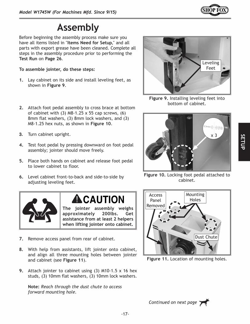
7. Remove access panel from rear of cabinet.
8. With help from assistants, lift jointer onto cabinet, and align all three mounting holes between jointer and cabinet (see Figure 11).
9. Attach jointer to cabinet using (3) M10-1.5 x 16 hex studs, (3) 10mm flat washers, (3) 10mm lock washers.
Note: Reach through the dust chute to access forward mounting hole.
Before beginning the assembly process make sure you have all items listed in "Items Need for Setup," and all parts with export grease have been cleaned. Complete all steps in the assembly procedure prior to performing the Test Run on Page 26.
To assemble jointer, do these steps:
1. Lay cabinet on its side and install leveling feet, as shown in Figure 9.
Figure 9. Installing leveling feet into bottom of cabinet.
2. Attach foot pedal assembly to cross brace at bottom of cabinet with (3) M8-1.25 x 55 cap screws, (6) 8mm flat washers, (3) 8mm lock washers, and (3) M8-1.25 hex nuts, as shown in Figure 10.
3. Turn cabinet upright.
4. Test foot pedal by pressing downward on foot pedal assembly; jointer should move freely.
5. Place both hands on cabinet and release foot pedal to lower cabinet to floor.
6. Level cabinet front-to-back and side-to-side by adjusting leveling feet.
Leveling Feet
The jointer assembly weighs approximately 200lbs. Get assistance from at least 2 helpers when lifting jointer onto cabinet.
Continued on next page
Figure 10. Locking foot pedal attached to cabinet.
x 3
Figure 11. Location of mounting holes.
Access Panel
Removed
Mounting Holes
Dust Chute

-18-
Model W1745W (For Machines Mfd. Since 9/15)SE
TUP
Figure 12. Example of pulleys parallel and aligned.
Alignment
Set Screw
Motor PulleyMotor
CutterheadPulley
Cutterhead
9. Verify cutterhead and motor pulley are aligned, as illustrated in Figure 12. If pulleys are aligned, go to Step 14.
— If pulleys are NOT aligned, loosen motor mount bolts/nuts shown in Figure 13, then shift motor horizontally as needed to align pulleys, retighten motor mount bolts/nuts.
Note: Make fine adjustments to pulley alignment by loosening set screws on hub of motor pulley (see Figure 12), aligning motor pulley with cutterhead pulley, then retightening set screws. Each pulley should be perfectly aligned, as shown in Figure 12.
10. Place V-belt on motor pulley, then roll belt onto cutterhead pulley (see Figure 14).
11. Loosen four bolts/nuts securing motor mount brackets (see Figure 13), allow motor to slide down so its weight tensions the belt, then retighten bolts/nuts.
Note: When properly tensioned, belt has approximately 1⁄2" deflection when moderate pressure is applied midway between the pulleys, as illustrated in Figure 14. If necessary, apply downward pressure on motor before securing motor mount brackets to attain proper belt tension.
Note: DO NOT use a mechanical device to push motor down farther than you can by hand or you will overtighten the V-belt, which may lead to shortened bearing life in the motor or cutterhead.
12. Replace cabinet access panel.
Figure 13. Example of motor bracket bolts (black arrows) and motor mount bolts
(white arrows).
Motor Pulley
Approximately1/2" Deflection
Cutterhead Pulley
Figure 14. Correct belt deflection when properly tensioned.
Motor Mount Bolts/Nuts
(1 of 4)
Motor Mount Bracket Bolts/Nuts (2 of 4)
-19-
Model W1745W (For Machines Mfd. Since 9/15)SETU
P
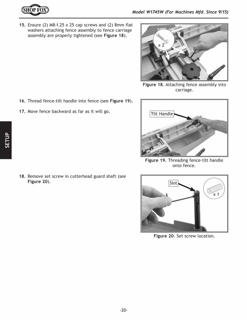
14. Secure fence carriage assembly to carriage mounting bracket with (2) M8-1.25 x 20 cap screws, (2) 8mm lock washers, and (2) 8mm flat washers (see Figure 17).
Note: Move fence carriage assembly through its full range of motion. If carriage is difficult to move, turn carriage set screw to adjust tension.
Figure 15. Attaching carriage mounting bracket to jointer table.
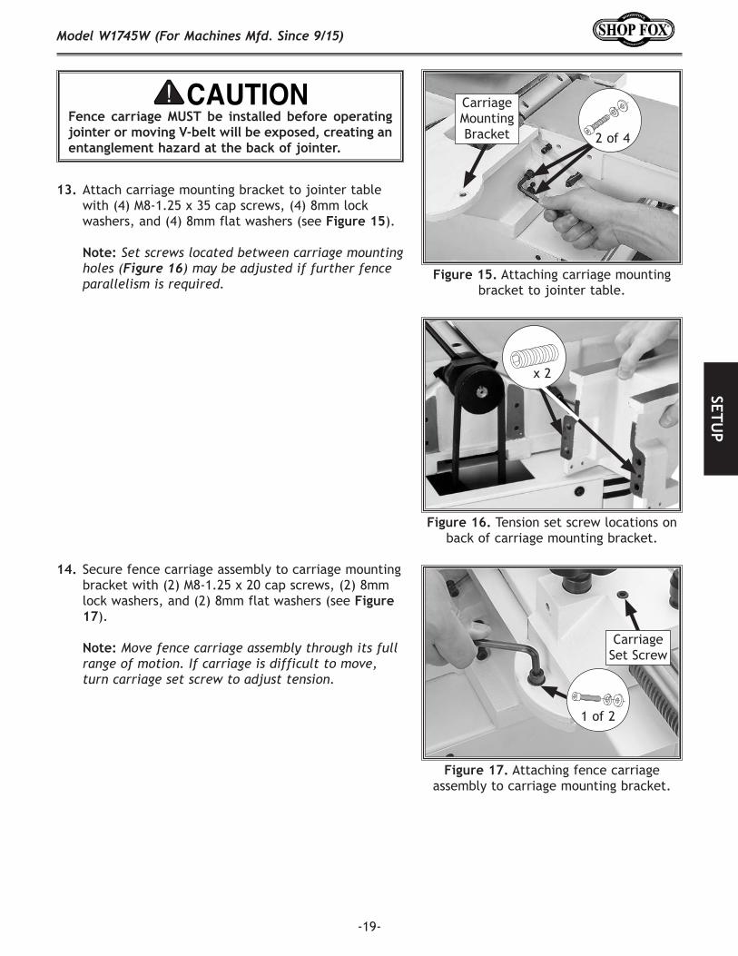
13. Attach carriage mounting bracket to jointer table with (4) M8-1.25 x 35 cap screws, (4) 8mm lock washers, and (4) 8mm flat washers (see Figure 15).
Note: Set screws located between carriage mounting holes (Figure 16).may be adjusted if further fence parallelism is required.
2 of 4
Carriage Mounting Bracket
Figure 16. Tension set screw locations on back of carriage mounting bracket.
x 2
Figure 17. Attaching fence carriage assembly to carriage mounting bracket.
1 of 2
Carriage Set Screw
Fence carriage MUST be installed before operating jointer or moving V-belt will be exposed, creating an entanglement hazard at the back of jointer.
-20-
Model W1745W (For Machines Mfd. Since 9/15)SE
TUP
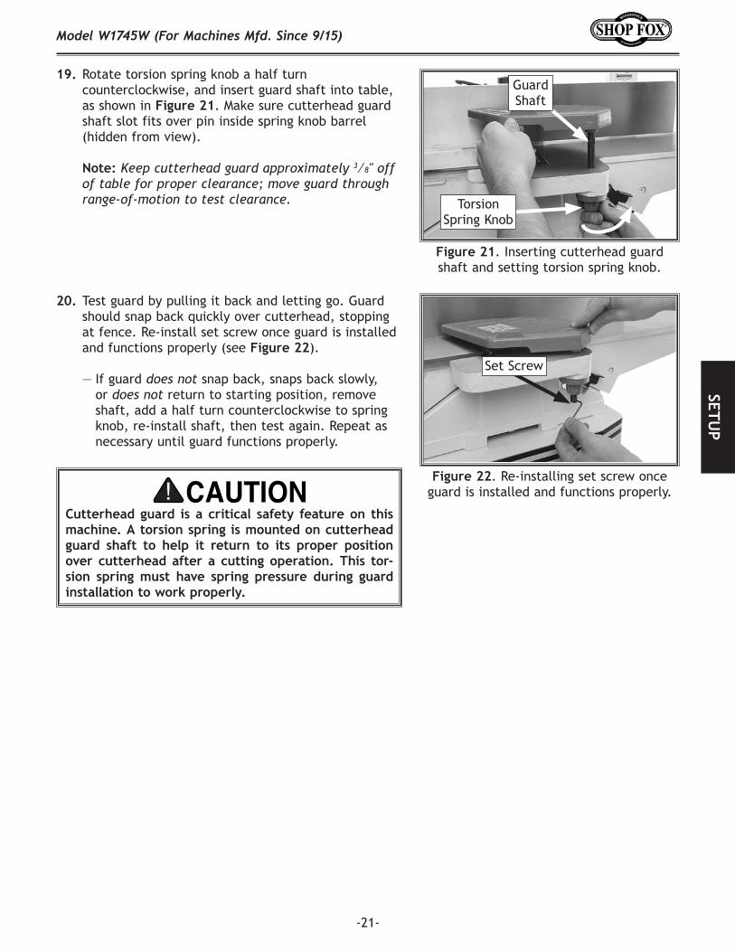
15. Ensure (2) M8-1.25 x 25 cap screws and (2) 8mm flat washers attaching fence assembly to fence carriage assembly are properly tightened (see Figure 18).
Figure 18. Attaching fence assembly into carriage.
16. Thread fence-tilt handle into fence (see Figure 19).
17. Move fence backward as far as it will go.
x 2
Figure 20. Set screw location.
x 1
Slot
18. Remove set screw in cutterhead guard shaft (see Figure 20).
Figure 19. Threading fence-tilt handle onto fence.
Tilt Handle
-21-
Model W1745W (For Machines Mfd. Since 9/15)SETU
P
19. Rotate torsion spring knob a half turn counterclockwise, and insert guard shaft into table, as shown in Figure 21. Make sure cutterhead guard shaft slot fits over pin inside spring knob barrel (hidden from view).
Note: Keep cutterhead guard approximately 3⁄8" off of table for proper clearance; move guard through range-of-motion to test clearance.
Figure 22. Re-installing set screw once guard is installed and functions properly.
Set Screw
Cutterhead guard is a critical safety feature on this machine. A torsion spring is mounted on cutterhead guard shaft to help it return to its proper position over cutterhead after a cutting operation. This tor-sion spring must have spring pressure during guard installation to work properly.
Figure 21. Inserting cutterhead guard shaft and setting torsion spring knob.
Guard Shaft
Torsion Spring Knob
20. Test guard by pulling it back and letting go. Guard should snap back quickly over cutterhead, stopping at fence. Re-install set screw once guard is installed and functions properly (see Figure 22).
— If guard does not snap back, snaps back slowly, or does not return to starting position, remove shaft, add a half turn counterclockwise to spring knob, re-install shaft, then test again. Repeat as necessary until guard functions properly.

-22-
Model W1745W (For Machines Mfd. Since 9/15)SE
TUP
21. Attach dust port to cabinet with (4) M5-.8 x 10 Phillips head screws and (4) 5mm flat washers (see Figure 23).
22. Attach support arm with (2) M8-1.25 x 15 hex bolts to back of infeed table, as shown in Figure 24.
Figure 23. Attaching dust port to cabinet.
Figure 24. Attaching support arm to infeed table.
x 4
X2
Figure 25. Securing cords to backside of control panel pedestal.
Power Cord
Cord Clamps
x 2
Control Panel Cord
23. Plug motor cord into backside of control box, then secure power cord and control panel cord with two cord clamps using M5-.8 x 10 Phillips head screws, as shown in Figure 25.
DO NOT operate this machine without an adequate dust collection system (see Dust Collection on Page 24). This machine creates substantial amounts of wood dust while operating. Failure to use a dust collection system can result in short and long-term respiratory illness.
-23-
Model W1745W (For Machines Mfd. Since 9/15)SETU
P
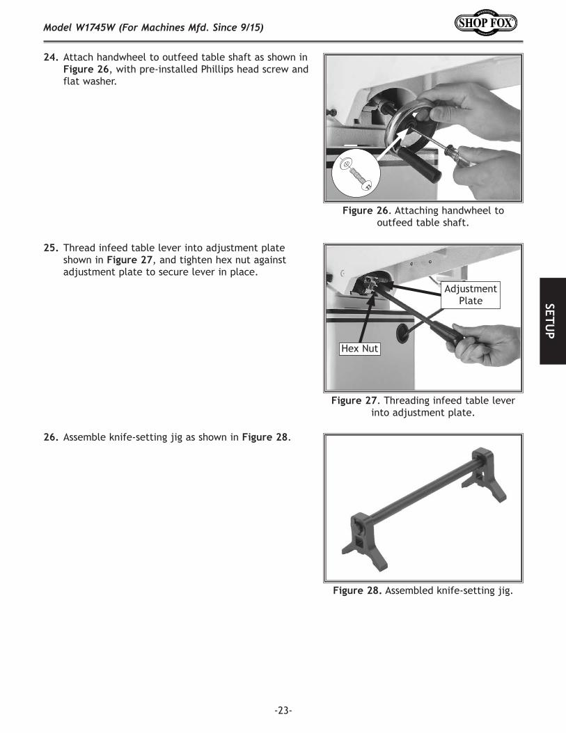
24. Attach handwheel to outfeed table shaft as shown in Figure 26, with pre-installed Phillips head screw and flat washer.
Figure 26. Attaching handwheel to outfeed table shaft.
25. Thread infeed table lever into adjustment plate shown in Figure 27, and tighten hex nut against adjustment plate to secure lever in place.
26. Assemble knife-setting jig as shown in Figure 28.
Figure 28. Assembled knife-setting jig.
Figure 27. Threading infeed table lever into adjustment plate.
Hex Nut
Adjustment Plate

-24-
Model W1745W (For Machines Mfd. Since 9/15)SE
TUP
Figure 29. Example of dust hose connected to dust port.
Recommended CFM at Dust Port: ................ 400 CFM
Dust Collection
Tools Needed QtyDust Collection System ........................................1Dust Hose 4" .....................................................1Hose Clamps 4" ..................................................2
To connect a dust collection hose, do these steps:
1. Fit a 4" dust hose over the dust port, as shown in Figure 29, and secure it in place with a hose clamp.
2. Tug the hose to make sure it does not come off.
Note: A tight fit is necessary for proper performance.
Do not confuse this CFM recommendation with the rating of the dust collector. To determine the CFM at the dust port, you must consider these variables: (1) CFM rating of the dust collector, (2) hose type and length between the dust collector and the machine, (3) number of branches or wyes, and (4) amount of other open lines throughout the system. Explaining how to calculate these variables is beyond the scope of this manual. Consult an expert or purchase a good dust collection “how-to” book.
This machine creates substantial amounts of dust during operation. Breathing airborne dust on a regular basis can result in permanent respiratory illness. Reduce your risk by wearing a respirator and capturing dust with a dust collection system.

-25-
Model W1745W (For Machines Mfd. Since 9/15)SETU
P
Setting Outfeed Table Height
During jointer operation, the outfeed table must be level with the knives when they are at top-dead-center (TDC). If the outfeed table is set too low, the workpiece will be tapered from front to back or there will be snipe (a gouge in end of board that is uneven with rest of cut). If the outfeed table is set too high, the workpiece will hit the edge of the outfeed table during operation, increasing the risk of kickback and related injuries.
The outfeed table adjustment will also have to be made any time you perform maintenance on the cutterhead or knives.
To set outfeed table height, do these steps:
1. DISCONNECT MACHINE FROM POWER!
2. Remove rear access panel and move/remove cutterhead guard away to access full length of table.
3. Rotate cutterhead pulley until a knife is at TDC, as illustrated in Figure 30.
4. Place straightedge on outfeed table so it extends over cutterhead. If knife lifts off of table, or knife is below straightedge, adjust outfeed table height until knife at TDC just touches straightedge.
5. If outfeed table is correctly set, knife at TDC should just touch straightedge, as shown in Figure 31.
6. Lock outfeed table in position (see Figure 32), and re-install/release cutterhead guard.
Top DeadCenter
Figure 30. Cutterhead knife at top-dead-center.
Figure 32. Outfeed table lock.
Straightedge
Outfeed Infeed
Figure 31. Using a straightedge to align outfeed table height with knife at TDC.
Table Lock
If outfeed table is set too high, workpiece will contact outfeed table edge during operation, increasing risk of kickback.
-26-
Model W1745W (For Machines Mfd. Since 9/15)SE
TUP
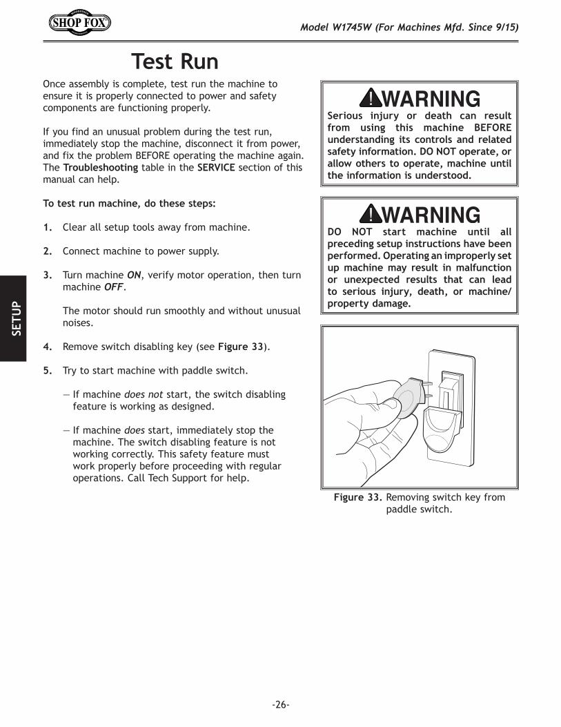
Figure 33. Removing switch key from paddle switch.
Test Run
Serious. injury. or. death. can. result.from. using. this. machine. BEFORE.understanding. its. controls. and. related.safety.information..DO.NOT.operate,.or.allow.others.to.operate,.machine.until.the.information.is.understood..
DO. NOT. start. machine. until. all.preceding.setup.instructions.have.been.performed..Operating.an.improperly.set.up.machine.may. result. in.malfunction.or. unexpected. results. that. can. lead.to. serious. injury,. death,. or. machine/property.damage.
Once assembly is complete, test run the machine to ensure it is properly connected to power and safety components are functioning properly.
If you find an unusual problem during the test run, immediately stop the machine, disconnect it from power, and fix the problem BEFORE operating the machine again. The Troubleshooting table in the SERVICE section of this manual can help.
To test run machine, do these steps:
1. Clear all setup tools away from machine.
2. Connect machine to power supply.
3. Turn machine ON, verify motor operation, then turn machine OFF.
The motor should run smoothly and without unusual
noises.
4. Remove switch disabling key (see Figure 33).
5. Try to start machine with paddle switch.
— If machine does not start, the switch disabling feature is working as designed.
— If machine does start, immediately stop the machine. The switch disabling feature is not working correctly. This safety feature must work properly before proceeding with regular operations. Call Tech Support for help.
-27-
Model W1745W (For Machines Mfd. Since 9/15)SETU
P
For your convenience, the adjustments listed below have been performed at the factory and no further setup is required to operate your machine.
However, because of the many variables involved with shipping, we recommend that you at least verify the following adjustments to ensure the best possible results from your new machine.
Step-by-step instructions for these adjustments can be found in SECTION 7: SERVICE.
Factory adjustments that should be verified:
1. Knife Settings (Page 40).
2. Depth Scale Calibration (Page 45).
3. Fence Stop Accuracy (Page 42).
4. Table Parallelism (Page 47).
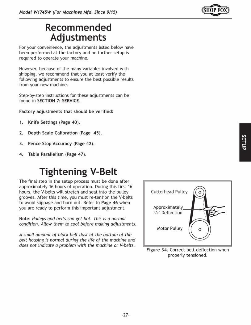
The final step in the setup process must be done after approximately 16 hours of operation. During this first 16 hours, the V-belts will stretch and seat into the pulley grooves. After this time, you must re-tension the V-belts to avoid slippage and burn out. Refer to Page 46 when you are ready to perform this important adjustment.
Note: Pulleys and belts can get hot. This is a normal condition. Allow them to cool before making adjustments.
A small amount of black belt dust at the bottom of the belt housing is normal during the life of the machine and does not indicate a problem with the machine or V-belts.
Recommended Adjustments
Tightening V-Belt
Figure 34. Correct belt deflection when properly tensioned.
Motor Pulley
Approximately1/2" Deflection
Cutterhead Pulley
-28-
Model W1745W (For Machines Mfd. Since 9/15)O
PER
ATIO
NS
OPERATIONSGeneral
This machine will perform many types of operations that are beyond the scope of this manual. Many of these operations can be dangerous or deadly if performed incorrectly.
The instructions in this section are written with the understanding that the operator has the necessary knowledge and skills to operate this machine. If at any time you are experiencing difficulties performing any operation, stop using the machine!
The overview below provides the novice machine operator with a basic understanding of how the machine is used during operation, so the machine controls/components discussed later in this manual are easier to understand. Due to its generic nature, this overview is NOT intended to be an instructional guide.
To. reduce. your. risk. of. serious. injury.or. damage. to. the. machine,. read. this.entire.manual.BEFORE.using.machine.
To. reduce. the. risk. of. eye. injury. and.long-term. respiratory. damage,. always.wear. safety. glasses. and. a. respirator.while.operating.this.machine.
DO NOT investigate problems or adjust the jointer while it is running. Wait until the machine is turned OFF, unplugged and all working parts have come to a complete stop before proceeding!
To complete typical operation, operator does following:
1. Examines workpiece to verify it is safe and suitable for cutting.
2. Adjusts fence for width of workpiece and locks it in place.
3. Adjusts fence tilt, if necessary, and tightens fence lock lever to secure angle setting.
4. Adjusts infeed table height to set depth-of-cut per pass.
5. Puts on safety glasses and respirator.
6. Locates push blocks.
7. Starts jointer.
8. Using push blocks, holds workpiece firmly against both the infeed table and fence, and slides it into cutterhead at a steady and controlled rate until entire length of workpiece has advanced beyond cutterhead to outfeed table.
9. Repeats Steps 5–8 until satisfied with the results.
10. Stops jointer.
Operation Overview
-29-
Model W1745W (For Machines Mfd. Since 9/15)O
PERATIO
NS
Stock Inspection & Requirements
Here are some rules to follow when choosing and jointing stock:
• DO NOT joint or surface plane stock that contains large or loose knots. Injury to the operator or dam-age to the workpiece can occur if the knots become dislodged during the cutting operation.
• DO NOT joint or surface plane against the grain direction. Cutting against the grain increases the likelihood of stock kickback, as well as tear-out on the workpiece.
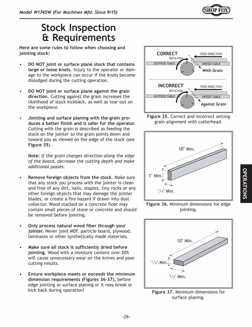
• Jointing and surface planing with the grain pro-duces a better finish and is safer for the operator. Cutting with the grain is described as feeding the stock on the jointer so the grain points down and toward you as viewed on the edge of the stock (see Figure 35).
Note: If the grain changes direction along the edge of the board, decrease the cutting depth and make additional passes.
• Remove foreign objects from the stock. Make sure that any stock you process with the jointer is clean and free of any dirt, nails, staples, tiny rocks or any other foreign objects that may damage the jointer blades, or create a fire hazard if drawn into dust collector. Wood stacked on a concrete floor may contain small pieces of stone or concrete and should be removed before jointing.
• Only process natural wood fiber through your jointer. Never joint MDF, particle board, plywood, laminates or other synthetically made materials.
• Make sure all stock is sufficiently dried before jointing. Wood with a moisture content over 20% will cause unnecessary wear on the knives and poor cutting results.
• Ensure workpiece meets or exceeds the minimum dimension requirements (Figures 36–37), before edge jointing or surface planing or it may break or kick back during operation!
Figure 35. Correct and incorrect setting grain alignment with cutterhead.
With Grain
Against Grain
CORRECT
INCORRECT
FEED DIRECTION
FEED DIRECTION
ROTATION
ROTATION
INFEED TABLEOUTFEED TABLE
INFEED TABLEOUTFEED TABLE
1⁄4" Min.
1" Min.
10" Min.
1⁄2" Min.
10" Min.
Figure 36. Minimum dimensions for edge jointing.
Figure 37. Minimum dimensions for surface planing.
3⁄4" Min.

-30-
Model W1745W (For Machines Mfd. Since 9/15)O
PER
ATIO
NS
The depth of cut on a jointer affects the amount of mate-rial removed from the bottom of the workpiece as it pass-es over the cutterhead.
The depth of cut is set by adjusting the height of the infeed table relative to the cutterhead knives/inserts at TDC (top dead center).
The depth stop can be used to set the maximum depth of cut to 1⁄8" for most jointing operations, and the depth-of-cut scale displays the depth of cut, which goes up to 1⁄2" for cutting rabbets (see Figure 38).
DO NOT exceed 1⁄8" cut per pass on this machine or kick-back and serious injury may occur!
Setting Depth of Cut
Figure 39. Infeed table lock.
Figure 40. Adjusting infeed table height.
Infeed Table Lock LeverUpper Stop
Screw
Lower Stop Screw
Stop Pin
Jam Nuts
To adjust positive-stop screws, do these steps:
1. Loosen jam nut and stop screws shown in Figure 39, but do not completely remove them.
2. Lower table to maximum desired depth of cut.
3. Tighten lower stop screw until it contacts stop pin shown in Figure 39, and then tighten lower jam nut to secure stop screw.
4. Raise table to minimum desired depth of cut, then repeat Step 3 with upper stop screw and jam nut.
Adjusting Infeed Table HeightTo adjust the infeed table height, loosen the infeed table lock (see Figure 39), move the infeed table lever up/down (see Figure 40) to raise or lower the table to the desire cut depth shown on the scale, and then tighten the table lock to secure the setting (see Figure 39).
Positive-Stop ScrewsThe infeed table features positive-stop screws (see Figure 39) that allow the operator to quickly adjust the infeed table between finish/final cuts and shaping/heavy cuts.
We recommend setting the minimum depth of cut to 1⁄32" and the maximum depth of cut to 1⁄8" for most opera-tions.
Figure 38. Depth scale components.
Depth Stop
Depth Indicator
Scale

-31-
Model W1745W (For Machines Mfd. Since 9/15)O
PERATIO
NS
15 30
45
PreviouslyJointedEdge
Squaring StockSquaring stock involves four steps performed in order below:
1. Surface Plane using Jointer: The concave face of the workpiece face is surface planed flat with the jointer (see Figure 41).
2. Surface Plane on a Thickness Planer: A thickness planer flattens opposite workpiece face (see Figure 42).
Figure 41. Surface plane using jointer.
Figure 42. Surface plane using thickness planer.
Figure 43. Edge joint using jointer.
Figure 44. Rip cut on table saw.
Previously SurfacePlaned Face
Previously Jointed
Edge
Previously Planed Face
3. Edge-Jointing using Jointer: A concave workpiece edge is jointed flat with jointer (see Figure 43).
4. Rip-Cut on a Table Saw: A jointed workpiece edge is placed against a table saw fence and opposite edge is cut off (see Figure 44).

-32-
Model W1745W (For Machines Mfd. Since 9/15)O
PER
ATIO
NS
Surface PlaningThe purpose of surface planing on the jointer is to make one flat face on a workpiece (see Figures 45–46). This is a necessary step when preparing a workpiece to be run through a thickness planer when squaring stock.
To surface plane on jointer, do these steps:
1. Inspect stock to ensure it is safe and suitable for the operation (see Stock Inspection & Requirements sec-tion).
2. Set infeed table height to desired cutting depth for each pass.
IMPORTANT: For safety reasons, do not exceed a cut-ting depth of 1⁄8" per pass when surface planing.
3. Setfenceto90˚.
4. Start jointer.
5. Place workpiece firmly against fence and infeed table.
IMPORTANT: To ensure workpiece remains stable dur-ing cut, concave sides of workpiece must face toward table and fence.
6. Feed workpiece completely across cutterhead while keeping it firmly against fence and tables during the entire cut.
IMPORTANT: Keep hands at least 4" away from cutterhead during the entire cut. Instead of allow-ing a hand to pass directly over cutterhead, lift it up and over cutterhead, and safely reposition it on the outfeed side to continue supporting workpiece. Use push blocks whenever practical to further reduce risk of accidental hand contact with cutterhead.
7. Repeat Step 6 until entire surface is flat.
Tip: When squaring up stock, cut opposite side of workpiece with a planer instead of the jointer to ensure both sides are parallel.
Figure 46. Typical surface planing operation.
Figure 45. Illustration of surface planing.
RemovedSurface
Failure to use push blocks when surface planing may result in cutterhead contact, which will cause serious personal injury. Always use push blocks to protect your hands when surface planing on the jointer.
If you are not experienced with a jointer, set depth of cut to "0", and practice feeding workpiece across tables as described. This procedure will better prepare you for actual operation.
RemovedSurface
-33-
Model W1745W (For Machines Mfd. Since 9/15)O
PERATIO
NS
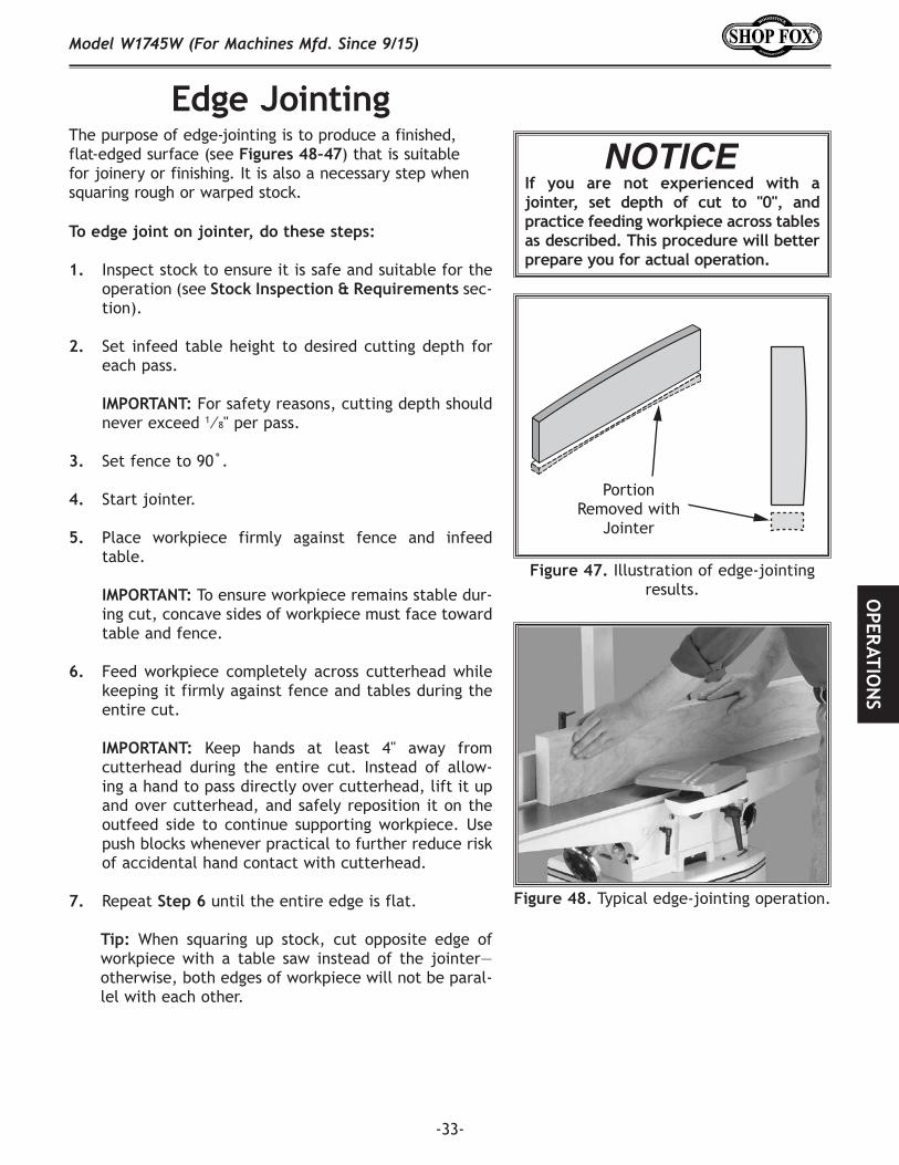
Edge JointingThe purpose of edge-jointing is to produce a finished, flat-edged surface (see Figures 48–47) that is suitable for joinery or finishing. It is also a necessary step when squaring rough or warped stock.
Figure 47. Illustration of edge-jointing results.
Figure 48. Typical edge-jointing operation.
RemovedSurface
Portion Removed with
Jointer
If you are not experienced with a jointer, set depth of cut to "0", and practice feeding workpiece across tables as described. This procedure will better prepare you for actual operation.
To edge joint on jointer, do these steps:
1. Inspect stock to ensure it is safe and suitable for the operation (see Stock Inspection & Requirements sec-tion).
2. Set infeed table height to desired cutting depth for each pass.
IMPORTANT: For safety reasons, cutting depth should never exceed 1⁄8" per pass.
3. Setfenceto90˚.
4. Start jointer.
5. Place workpiece firmly against fence and infeed table.
IMPORTANT: To ensure workpiece remains stable dur-ing cut, concave sides of workpiece must face toward table and fence.
6. Feed workpiece completely across cutterhead while keeping it firmly against fence and tables during the entire cut.
IMPORTANT: Keep hands at least 4" away from cutterhead during the entire cut. Instead of allow-ing a hand to pass directly over cutterhead, lift it up and over cutterhead, and safely reposition it on the outfeed side to continue supporting workpiece. Use push blocks whenever practical to further reduce risk of accidental hand contact with cutterhead.
7. Repeat Step 6 until the entire edge is flat.
Tip: When squaring up stock, cut opposite edge of workpiece with a table saw instead of the jointer—otherwise, both edges of workpiece will not be paral-lel with each other.

-34-
Model W1745W (For Machines Mfd. Since 9/15)O
PER
ATIO
NS
Bevel CuttingBevel cuts (see Figures 49–50) can be made by setting the fence at the desired angle and feeding the workpiece firmly along the fence face, with the bottom inside cor-ner firmly against the table. The cutting process typically requires multiple passes or cuts to bevel the entire edge of a workpiece.
To bevel cut on jointer, do these steps:
1. Inspect stock to ensure it is safe and suitable for the operation (see Stock Inspection & Requirements section).
2. Set infeed table height to cutting depth desired for each pass.
Note: Cutting depth for bevel cuts is typically between 1⁄16" and 1⁄8", depending on hardness and width of stock.
3. Set fence tilt to desired angle of cut.
4. Place workpiece against fence and infeed table with concave side face down.
5. Start jointer.
6. With a push block in your leading hand, press workpiece against table and fence with firm pres-sure, and feed workpiece over cutterhead with a push block in your trailing hand.
Note: When your leading hand gets within 4" of the cutterhead, lift it up and over cutterhead, and place push block on portion of the workpiece once it is 4" past cutterhead. Now, focus your pressure on outfeed end of the workpiece while feeding, and repeat same action with your trailing hand when it gets within 4" of cutterhead. To help keep your hands safe, DO NOT let them get closer than 4" from moving cutterhead at any time during operation!
7. Repeat cutting process, as necessary, until you are satisfied with results.
Figure 50. Typical bevel-cutting operation.
Figure 49. Illustration of bevel-cutting results.
RemovedSurface
If you are not experienced with a jointer, set depth of cut to "0", and practice feeding workpiece across tables as described. This procedure will better prepare you for actual operation.
-35-
Model W1745W (For Machines Mfd. Since 9/15)O
PERATIO
NS
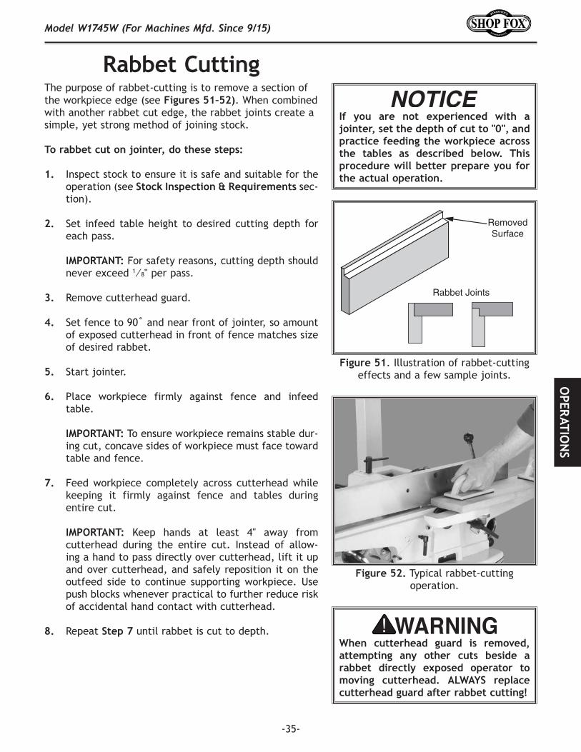
Rabbet CuttingThe purpose of rabbet-cutting is to remove a section of the workpiece edge (see Figures 51–52). When combined with another rabbet cut edge, the rabbet joints create a simple, yet strong method of joining stock.
To rabbet cut on jointer, do these steps:
1. Inspect stock to ensure it is safe and suitable for the operation (see Stock Inspection & Requirements sec-tion).
2. Set infeed table height to desired cutting depth for each pass.
IMPORTANT: For safety reasons, cutting depth should never exceed 1⁄8" per pass.
3. Remove cutterhead guard.
4. Setfenceto90˚andnearfrontofjointer,soamountof exposed cutterhead in front of fence matches size of desired rabbet.
5. Start jointer.
6. Place workpiece firmly against fence and infeed table.
IMPORTANT: To ensure workpiece remains stable dur-ing cut, concave sides of workpiece must face toward table and fence.
7. Feed workpiece completely across cutterhead while keeping it firmly against fence and tables during entire cut.
IMPORTANT: Keep hands at least 4" away from cutterhead during the entire cut. Instead of allow-ing a hand to pass directly over cutterhead, lift it up and over cutterhead, and safely reposition it on the outfeed side to continue supporting workpiece. Use push blocks whenever practical to further reduce risk of accidental hand contact with cutterhead.
8. Repeat Step 7 until rabbet is cut to depth.
Figure 52. Typical rabbet-cutting operation.
Figure 51. Illustration of rabbet-cutting effects and a few sample joints.
RemovedSurface
Rabbet Joints
If you are not experienced with a jointer, set the depth of cut to "0", and practice feeding the workpiece across the tables as described below. This procedure will better prepare you for the actual operation.
When cutterhead guard is removed, attempting any other cuts beside a rabbet directly exposed operator to moving cutterhead. ALWAYS replace cutterhead guard after rabbet cutting!
-36-
Model W1745W (For Machines Mfd. Since 9/15)O
PER
ATIO
NS
ACCESSORIESJointer Accessories
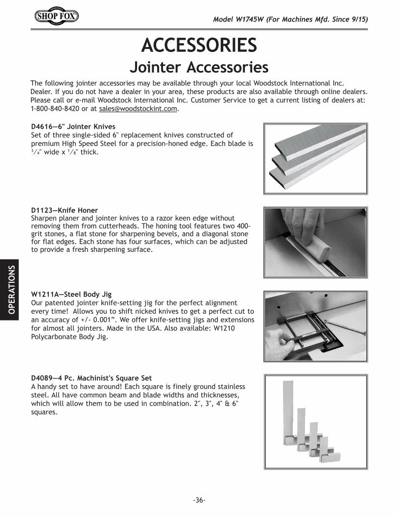
The following jointer accessories may be available through your local Woodstock International Inc. Dealer. If you do not have a dealer in your area, these products are also available through online dealers. Please call or e-mail Woodstock International Inc. Customer Service to get a current listing of dealers at: 1-800-840-8420 or at [email protected].
D1123—Knife HonerSharpen planer and jointer knives to a razor keen edge without removing them from cutterheads. The honing tool features two 400-grit stones, a flat stone for sharpening bevels, and a diagonal stone for flat edges. Each stone has four surfaces, which can be adjusted to provide a fresh sharpening surface.
W1211A—Steel Body Jig Our patented jointer knife-setting jig for the perfect alignment every time! Allows you to shift nicked knives to get a perfect cut to an accuracy of +/- 0.001”. We offer knife-setting jigs and extensions for almost all jointers. Made in the USA. Also available: W1210 Polycarbonate Body Jig.
D4616—6" Jointer KnivesSet of three single-sided 6" replacement knives constructed of premium High Speed Steel for a precision-honed edge. Each blade is 3⁄4" wide x 1⁄8" thick.
D4089—4 Pc. Machinist's Square Set A handy set to have around! Each square is finely ground stainless steel. All have common beam and blade widths and thicknesses, which will allow them to be used in combination. 2", 3", 4" & 6" squares.

-37-
Model W1745W (For Machines Mfd. Since 9/15)M
AIN
TENA
NCE
MAINTENANCE
MAKE SURE that your machine is unplugged during all maintenance pro-cedures! If this warning is ignored, serious personal injury may occur.
Cleaning the W1745W is relatively easy. Vacuum excess wood chips and sawdust, and wipe off the remaining dust with a dry cloth. If any resin has built up, use a resin-desolving cleaner to remove it.
Protect the unpainted cast-iron table by wiping it clean after every use—this ensures moisture from wood dust does not remain on bare metal surfaces. Keep the table rust-free with regular applications of quality lubricants.
Cleaning & Protecting
For optimum performance from your machine, follow this maintenance schedule and refer to any specific instructions given in this section.
Daily Check:• Inspect cutters for damage or wear.• Check for loose mounting bolts/nuts.• Check cords, plugs, and switch for damage.• Check for the proper function of the cutter guard
(see Page 21).• Check for any other condition that could hamper the
safe operation of this machine.• Wipe the table clean after every use—this ensures
moisture from wood dust does not remain on bare metal surfaces.
Weekly Maintenance:• Wipe down the table surface and grooves with a
lubricant and rust preventive such as SLIPIT®.• Vacuum dust buildup from the motor housing and
inside cabinet.• Clean the pitch and resin from cutterhead with a
cleaner like OxiSolv® Blade & Bit Cleaner.
Monthly Maintenance:• Check/tighten the V-belt tension (Page 18).
Every 6–12 Months:• Lubricate table gibs and ways.
General
-38-
Model W1745W (For Machines Mfd. Since 9/15)SE
RVIC
E
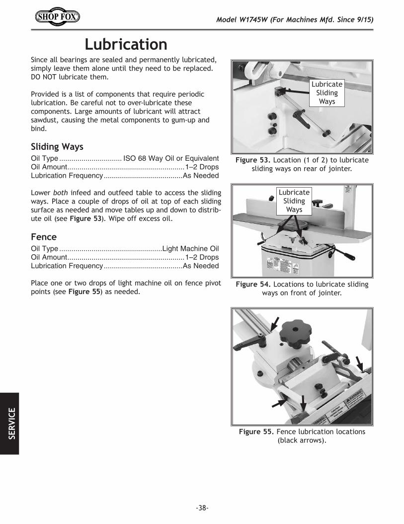
LubricationSince all bearings are sealed and permanently lubricated, simply leave them alone until they need to be replaced. DO NOT lubricate them.
Provided is a list of components that require periodic lubrication. Be careful not to over-lubricate these components. Large amounts of lubricant will attract sawdust, causing the metal components to gum-up and bind.
Sliding WaysOil Type ............................... ISO 68 Way Oil or EquivalentOil Amount ..........................................................1–2 DropsLubrication Frequency .......................................As Needed
Lower both infeed and outfeed table to access the sliding ways. Place a couple of drops of oil at top of each sliding surface as needed and move tables up and down to distrib-ute oil (see Figure 53). Wipe off excess oil.
Fence Oil Type ...................................................Light Machine OilOil Amount ..........................................................1–2 DropsLubrication Frequency .......................................As Needed
Place one or two drops of light machine oil on fence pivot points (see Figure 55) as needed.
Figure 53. Location (1 of 2) to lubricate sliding ways on rear of jointer.
Lubricate Sliding Ways
Figure 55. Fence lubrication locations (black arrows).
Figure.54. Locations to lubricate sliding ways on front of jointer.
Lubricate Sliding Ways
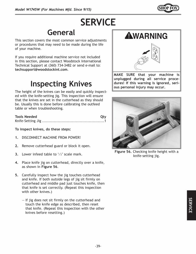
-39-
Model W1745W (For Machines Mfd. Since 9/15)SERVICE
SERVICEGeneral
MAKE. SURE. that. your. machine. is.unplugged. during. all. service. proce-dures!. If. this. warning. is. ignored,. seri-ous.personal.injury.may.occur.Inspecting Knives
The height of the knives can be easily and quickly inspect-ed with the knife-setting jig. This inspection will ensure that the knives are set in the cutterhead as they should be. Usually this is done before calibrating the outfeed table or when troubleshooting.
Tools Needed QtyKnife-Setting Jig ................................................1
To inspect knives, do these steps:
1. DISCONNECT MACHINE FROM POWER!
2. Remove cutterhead guard or block it open.
3. Lower infeed table to 1⁄2" scale mark.
4. Place knife jig on cutterhead, directly over a knife, as shown in Figure 56.
5. Carefully inspect how the jig touches cutterhead and knife. If both outside legs of jig sit firmly on cutterhead and middle pad just touches knife, then that knife is set correctly. (Repeat this inspection with other knives.)
— If jig does not sit firmly on the cutterhead and touch the knife edge as described, then reset that knife. (Repeat this inspection with the other knives before resetting.)
Figure 56. Checking knife height with a knife-setting jig.
This section covers the most common service adjustments or procedures that may need to be made during the life of your machine.
If you require additional machine service not included in this section, please contact Woodstock International Technical Support at (360) 734-3482 or send e-mail to: [email protected].
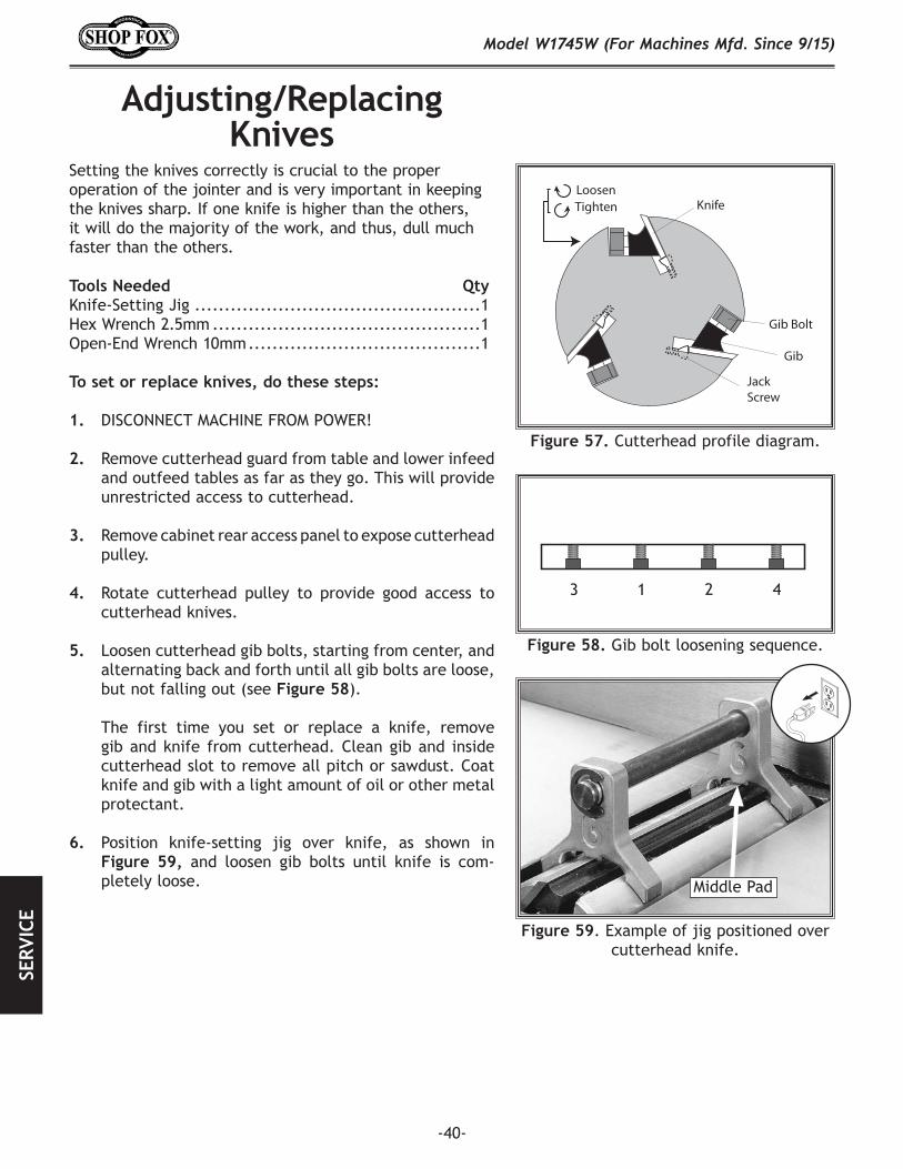
-40-
Model W1745W (For Machines Mfd. Since 9/15)SE
RVIC
E
Figure 59. Example of jig positioned over cutterhead knife.
Middle Pad
Setting the knives correctly is crucial to the proper operation of the jointer and is very important in keeping the knives sharp. If one knife is higher than the others, it will do the majority of the work, and thus, dull much faster than the others.
Tools Needed QtyKnife-Setting Jig ................................................1Hex Wrench 2.5mm .............................................1Open-End Wrench 10mm .......................................1
To set or replace knives, do these steps:
1. DISCONNECT MACHINE FROM POWER!
2. Remove cutterhead guard from table and lower infeed and outfeed tables as far as they go. This will provide unrestricted access to cutterhead.
3. Remove cabinet rear access panel to expose cutterhead pulley.
4. Rotate cutterhead pulley to provide good access to cutterhead knives.
5. Loosen cutterhead gib bolts, starting from center, and alternating back and forth until all gib bolts are loose, but not falling out (see Figure 58).
The first time you set or replace a knife, remove gib and knife from cutterhead. Clean gib and inside cutterhead slot to remove all pitch or sawdust. Coat knife and gib with a light amount of oil or other metal protectant.
6. Position knife-setting jig over knife, as shown in Figure 59, and loosen gib bolts until knife is com-pletely loose.
Adjusting/Replacing Knives
1 423
Figure 58. Gib bolt loosening sequence.
Loosen Tighten Knife
Gib Bolt
Gib
Jack Screw
Figure 57. Cutterhead profile diagram.

-41-
Model W1745W (For Machines Mfd. Since 9/15)SERVICE
Tightens Knife
Loosens Knife
Figure 61. Gib bolt loosening/tightening direction.
Figure 62. Gib bolt tightening sequence.
7. Use a 2.5mm hex wrench to rotate jack screws to raise or lower knife. When knife is set correctly, it will barely touch middle pad of knife-setting jig (see Figure 60).
Figure 60. Using knife-setting jig to set knife height.
1 423
8. Snug gib bolts tight enough to just hold knife in place.
9. Repeat Steps 5–9 with remaining knives.
10. Rotate cutterhead to first knife you started with. Slightly tighten all gib bolts, starting at middle and working your way to ends by alternating left and right (Figure 62). Repeat this step with remaining knives.
11. Repeat Step 11, but fully tighten each gib bolt (see Figure 61).
12. Adjust outfeed table to match new knife heights (refer to Setting Outfeed Table Height on Page 25).
13. Replace cutterhead guard and cabinet rear access panel.
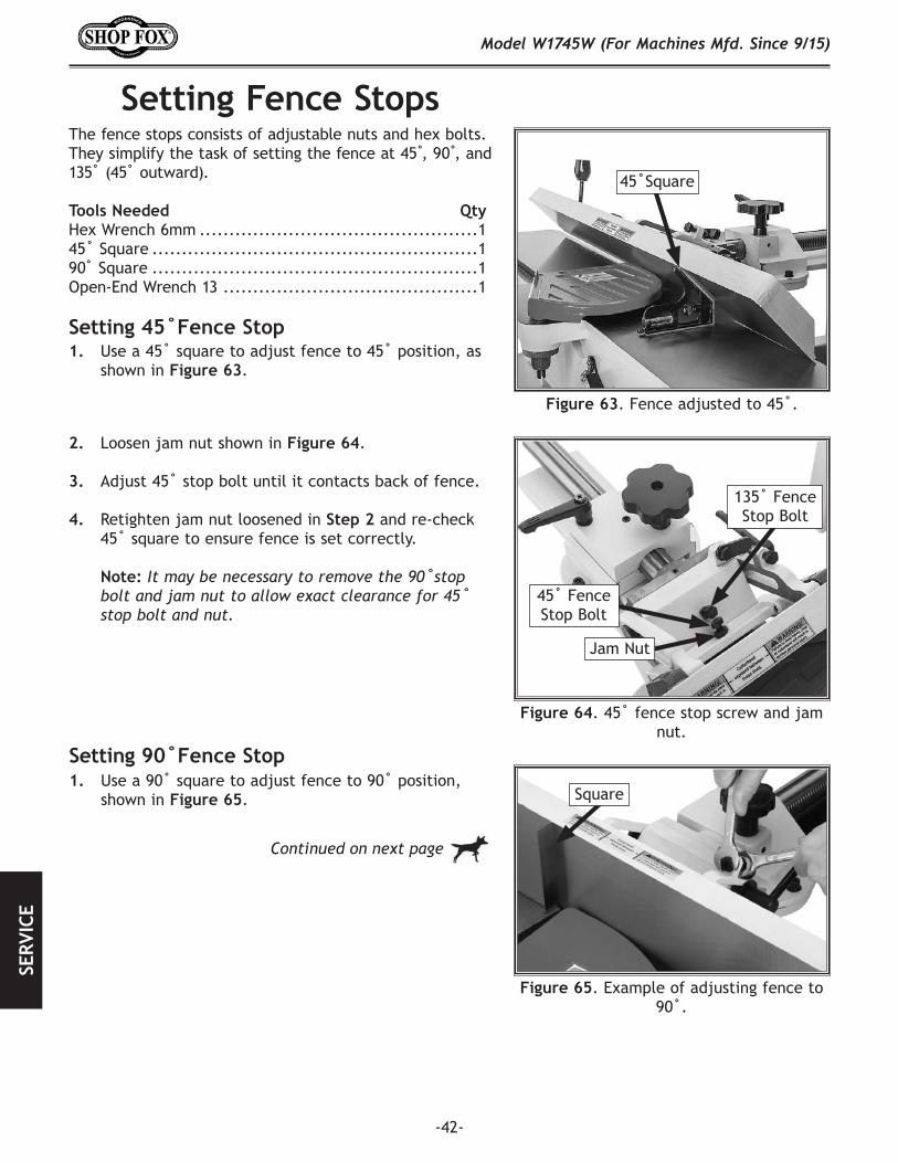
-42-
Model W1745W (For Machines Mfd. Since 9/15)SE
RVIC
E
Setting Fence Stops
Figure 63. Fence adjusted to 45˚.
The fence stops consists of adjustable nuts and hex bolts. They simplify the task of setting the fence at45 ,̊90 ,̊and 135˚(45˚ outward). Tools Needed QtyHex Wrench 6mm ...............................................145˚Square .......................................................190˚ Square .......................................................1Open-End Wrench 13 ...........................................1
Figure 64.45˚fence stop screw and jam nut.
45˚Square
Jam Nut
45˚FenceStop Bolt
135˚FenceStop Bolt
2. Loosen jam nut shown in Figure 64.
3. Adjust45˚stopbolt until it contacts back of fence.
4. Retighten jam nut loosened in Step 2 and re-check 45˚ square to ensure fence is set correctly.
Note: It may be necessary to remove the 90˚stop bolt and jam nut to allow exact clearance for 45˚ stop bolt and nut.
1. Usea45˚square toadjustfenceto45˚position,asshown in Figure 63.
Setting 45˚Fence Stop
Figure 65. Example of adjusting fence to 90˚.
1. Usea90˚square to adjustfenceto90˚position, shown in Figure 65.
Setting 90˚Fence Stop
Continued on next page
Square

-43-
Model W1745W (For Machines Mfd. Since 9/15)SERVICE
Figure 67. Adjusting fence to 135°.
2. Rotate90˚swing-stop into position shown in Figure 66.
3. Loosenjamnuton90˚ stop bolt (see Figure 66).
4. Adjust90˚stopboltuntilitmakescontactwith90˚ swing-stop.
5. Retighten jam nut loosened in Step 3 and re-check 90˚ square to ensure fence is set correctly.
1. Disengage 90˚swing-stop, as shown in Figure 67.
2. Using angle gauge set for135˚,adjustfenceto135˚(45˚outward)position.
3. Loosen jam nut on 135° stop bolt (see Figure 68).
4. Turn 135° stop bolt to adjust fence angle. Bolt head will act as a stop by resting on backside of fence.
Swing-Stop
90˚Swing-Stop
Jam Nut
Figure 66.90˚swing-stop engaged.
Setting 135˚ Fence Stop
Figure 69. Checking and adjusting 135° angle with gauge.
Figure 68. 135° stop screw and jam nut.
135˚FenceStop Bolt
Jam Nut
5. Retighten jam nut loosened in Step 3 (see Figure 68), and re-check 135° gauge to ensure fence is set correctly.
Angle Gauge
90˚Fence-StopBolt

-44-
Model W1745W (For Machines Mfd. Since 9/15)SE
RVIC
E
Adjusting GibsAdjustment of the table gibs allows you to control the amount of play in the table movement, which determines how easy the tables move up and down.
Both tables have their own gibs that function and adjust in the same manner.
Note: Poorly lubricated sliding ways, or those that become gummed-up with dust/oil, will often feel similar to an over-tightened gibs. Table movement can often be improved by simply cleaning/lubricating the sliding ways regularly. We recommend that you do this prior to making any adjustments.
Tools Needed QtyHex Wrench 4mm ...............................................1Open-End Wrench 10mm.......................................1
To adjust table gibs, do these steps:
1. Loosen both jam nuts on the gib screws shown in Figure 70.
2. Oil gibs if needed (refer to Page 38).
3. Evenly tighten gib set screws a small amount, then check table by moving it up and down. Adjust set screws as needed until table movement is free of friction and is balanced with minimal play and ease of movement.
Note: Tighter gibs reduce play but make it harder to adjust tables.
5. Set outfeed table height as described in Setting Outfeed Table Height on Page 25.
Figure 70. Outfeed table gib controls.
Gib Screws
Jam Nuts
Set outfeed table height as described in Setting Outfeed Table Height on Page 25.
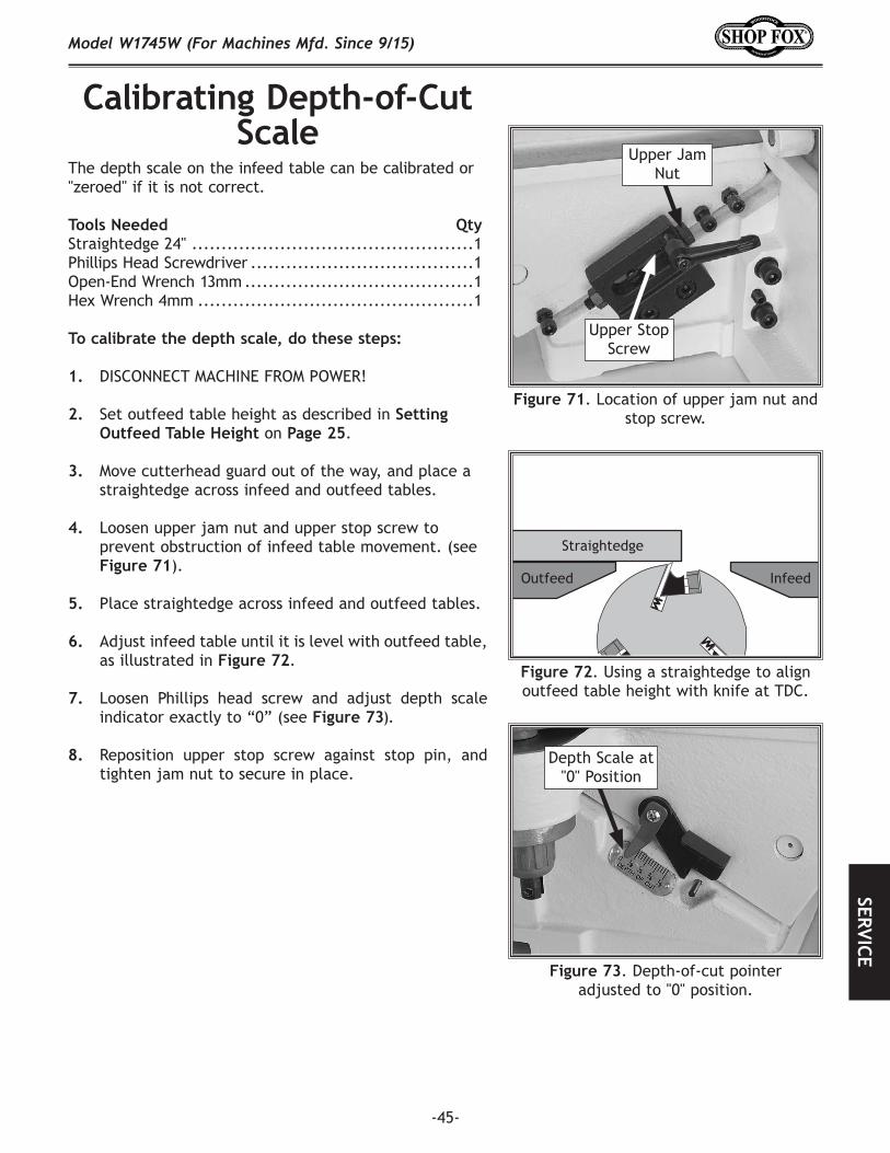
-45-
Model W1745W (For Machines Mfd. Since 9/15)SERVICE
Calibrating Depth-of-Cut Scale
The depth scale on the infeed table can be calibrated or "zeroed" if it is not correct.
Tools Needed QtyStraightedge 24" ................................................1Phillips Head Screwdriver ......................................1Open-End Wrench 13mm .......................................1Hex Wrench 4mm ...............................................1
To calibrate the depth scale, do these steps:
1. DISCONNECT MACHINE FROM POWER!
2. Set outfeed table height as described in Setting Outfeed Table Height on Page 25.
3. Move cutterhead guard out of the way, and place a straightedge across infeed and outfeed tables.
4. Loosen upper jam nut and upper stop screw to prevent obstruction of infeed table movement. (see Figure 71).
5. Place straightedge across infeed and outfeed tables.
6. Adjust infeed table until it is level with outfeed table, as illustrated in Figure 72.
7. Loosen Phillips head screw and adjust depth scale indicator exactly to “0” (see Figure 73).
8. Reposition upper stop screw against stop pin, and tighten jam nut to secure in place.
Figure 73. Depth-of-cut pointer adjusted to "0" position.
Depth Scale at "0" Position
Figure 71. Location of upper jam nut and stop screw.
Upper Jam Nut
Upper Stop Screw
Straightedge
Outfeed Infeed
Figure 72. Using a straightedge to align outfeed table height with knife at TDC.

-46-
Model W1745W (For Machines Mfd. Since 9/15)SE
RVIC
E
Tensioning/Replacing V-Belts
To ensure optimum power transmission from the motor to the cutterhead, the V-belt must be in good condition (free from cracks, fraying and wear) and properly tensioned. As the machine is used over time, the belts will slightly wear and stretch, eventually losing their efficiency of transmit-ting power, until they can be re-tensioned.
Also, new belts typically have a break-in period and should be checked/re-tensioned after the first 16 hours of belt life, as it will stretch and seat during this time.
Tensioning V-Belt
Figure 74. Example of motor mount bracket bolts/nuts.
Replacing V-Belt1. DISCONNECT MACHINE FROM POWER!
2. Remove cabinet rear access panel, and loosen motor mount bracket fasteners shown in Figure 74.
3. Have another person lift motor as you remove V-belt and replace it with a new one. Make sure V-belt is seated in pulley.
4. Follow Steps 4–5 in Tensioning V-Belt on this page to set correct belt tension, then tighten motor mount bracket fasteners (see Figure 74), and replace cabi-net rear access panel.
1. DISCONNECT MACHINE FROM POWER!
2. Remove cabinet rear access panel, and loosen motor mount bracket fasteners shown in Figure 74.
Note: DO NOT completely remove motor mount bracket fasteners.
4. Press down on motor to keep tension on belt.
5. Press belt with moderate pressure in center to check belt tension. Belt is correctly tensioned when there is approximately 1⁄2" deflection when pushed, as shown in Figure 75.
— If there is more than 1⁄2" deflection when you check belt tension, repeat the tensioning procedure until it is correct.
6. Tighten motor mount bracket fasteners (see Figure 74), and replace cabinet rear access panel.
Figure 75. Correct belt deflection when properly tensioned.
Motor Pulley
Approximately1/2" Deflection
Cutterhead Pulley
Motor Mount Bolts/Nuts
(1 of 4)
Motor Mount Bracket Bolts/Nuts (2 of 4)
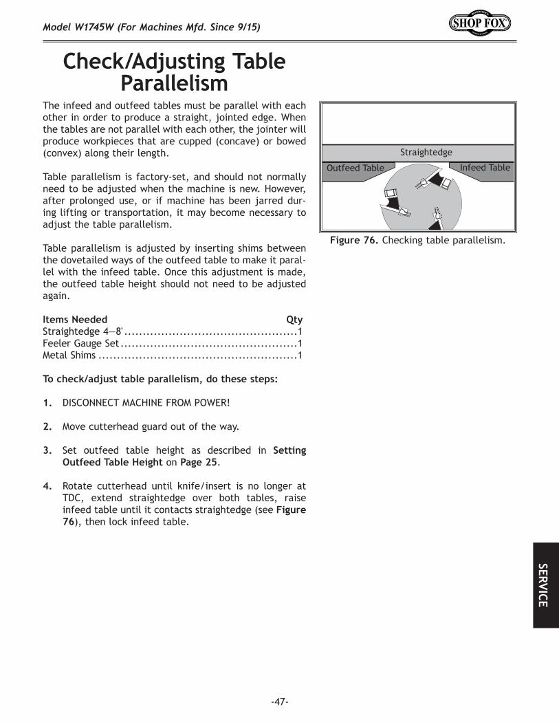
-47-
Model W1745W (For Machines Mfd. Since 9/15)SERVICE
Check/Adjusting Table Parallelism
The infeed and outfeed tables must be parallel with each other in order to produce a straight, jointed edge. When the tables are not parallel with each other, the jointer will produce workpieces that are cupped (concave) or bowed (convex) along their length.
Table parallelism is factory-set, and should not normally need to be adjusted when the machine is new. However, after prolonged use, or if machine has been jarred dur-ing lifting or transportation, it may become necessary to adjust the table parallelism.
Table parallelism is adjusted by inserting shims between the dovetailed ways of the outfeed table to make it paral-lel with the infeed table. Once this adjustment is made, the outfeed table height should not need to be adjusted again.
Items Needed QtyStraightedge 4—8' ...............................................1Feeler Gauge Set ................................................1Metal Shims ......................................................1
To check/adjust table parallelism, do these steps:
1. DISCONNECT MACHINE FROM POWER!
2. Move cutterhead guard out of the way.
3. Set outfeed table height as described in Setting Outfeed Table Height on Page 25.
4. Rotate cutterhead until knife/insert is no longer at TDC, extend straightedge over both tables, raise infeed table until it contacts straightedge (see Figure 76), then lock infeed table.
Straightedge
Outfeed Table Infeed Table
Figure 76. Checking table parallelism.
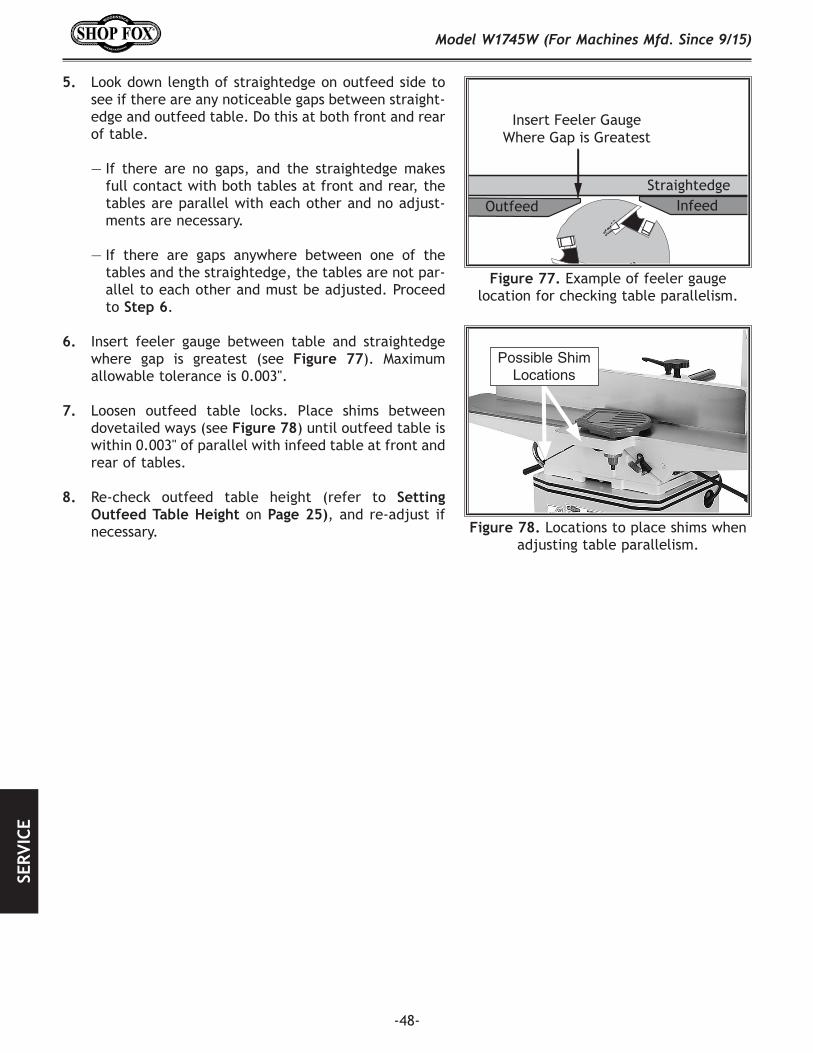
-48-
Model W1745W (For Machines Mfd. Since 9/15)SE
RVIC
E
5. Look down length of straightedge on outfeed side to see if there are any noticeable gaps between straight-edge and outfeed table. Do this at both front and rear of table.
— If there are no gaps, and the straightedge makes full contact with both tables at front and rear, the tables are parallel with each other and no adjust-ments are necessary.
— If there are gaps anywhere between one of the tables and the straightedge, the tables are not par-allel to each other and must be adjusted. Proceed to Step 6.
6. Insert feeler gauge between table and straightedge where gap is greatest (see Figure 77). Maximum allowable tolerance is 0.003".
7. Loosen outfeed table locks. Place shims between dovetailed ways (see Figure 78) until outfeed table is within 0.003" of parallel with infeed table at front and rear of tables.
8. Re-check outfeed table height (refer to Setting Outfeed Table Height on Page 25), and re-adjust if necessary.
StraightedgeInfeedOutfeed
Insert Feeler GaugeWhere Gap is Greatest
Figure 77. Example of feeler gauge location for checking table parallelism.
Figure 78. Locations to place shims when adjusting table parallelism.
Possible Shim Locations

-49-
Model W1745W (For Machines Mfd. Since 9/15)SERVICE
Troubleshooting
Motor and ElectricalPROBLEM POSSIBLE CAUSE CORRECTIVE ACTION
Machine does not start or breaker trips immediately after startup.
1. Switch disabling key removed.2. Incorrect power supply voltage/circuit size.3. Power supply circuit breaker tripped/fuse
blown. 4. Motor wires connected incorrectly.5. Wiring open/has high resistance.
6. ON switch at fault. 7. Centrifugal switch at fault. 8. Start capacitor at fault.9. Motor at fault.
1. Install switch disabling key.2. Ensure correct power supply voltage/circuit size.3. Ensure circuit is sized correctly and free of shorts.
Reset circuit breaker or replace fuse.4. Correct motor wiring connections (Page 52).5. Check/fixbroken,disconnected,orcorroded
wires.6. Test/replace switch.7. Adjust/replace centrifugal switch if available.8. Test/replace capacitor.9. Test/repair/replace.
Machine stalls or is underpowered.
1. Workpiece material not suitable. 2. Excessive feed rate.3. Excessive cutting depth.4. Dull knives. 5. Dust collection problem, causing internal
components to clog up with shavings.6. Belt slipping; oil/grease on belt.
7. Pulley loose or not properly aligned.
8. Motor overheated. 9. Motor wires connected incorrectly.10. Plug/receptacle at fault.11. Motor at fault.
1. Ensure workpiece is suitable for jointing (Page 29).2. Reduce feed rate.3. Reduce cutting depth (Page 30).4. Sharpen/replace knives (Page 40).5. Clear blockages; move machine closer to dust
collector; upgrade dust collector.6. Tension/replace belt (Page 46); clean belt; ensure
pulleys are aligned (Page 18).7. Re-align pulleys; replace shaft key; tighten pulley
set screw. 8. Clean motor, let cool, and reduce depth of cut.9. Correct motor wiring connections (Page 51).10. Test for good contacts/correct wiring.11. Test/repair/replace.
Machine has vibration or noisy operation.
1. Motor or other component loose.
2. Belt worn/loose; belt slapping cover.3. Pulley loose or not properly aligned.
4. Motor fan rubbing on fan cover.5. Mobile base caster engaged.6. Knives at fault.
7. Cutterhead bearings at fault.8. Centrifugal switch at fault.9. Motor bearings at fault.
1. Replace damaged bolts/nuts; retighten loose bolts/nuts.Usethread-lockingfluidifconditionrepeats.
2. Tension/replace belt (Page 46).3. Re-align pulleys; replace shaft key; tighten pulley
set screw. 4. Fix/replace fan cover; replace loose/damaged fan.5. Release mobile base caster to stabilize machine.6. Sharpen/replace knives; set knife alignment/
height correctly (Page 40).7. Replace bearing(s)/realign cutterhead.8. Replace.9. Test by rotating shaft; rotational grinding/loose
shaft requires bearing replacement.
The following troubleshooting tables cover common problems that may occur with this machine. If you need replacement parts or additional troubleshooting help, contact our Technical Support.
Note: Before contacting Tech Support, find the machine serial number and manufacture date, and if available, your original purchase receipt. This information is required to properly assist you.

-50-
Model W1745W (For Machines Mfd. Since 9/15)SE
RVIC
E
PROBLEM POSSIBLE CAUSE CORRECTIVE ACTION
Table(s) difficult to adjust.
1. Table lock(s) engaged/partially engaged.2. Infeed table stops blocking movement.
1. Completely loosen table lock(s) (Page 30).2. Loosen/reset infeed table stops (Page 30).
Excessive snipe (gouge in end of board that is uneven with rest of cut).
1. Outfeed table set too low; or knives set too high.
2. Operator pushing down on trailing end of workpiece as it leaves cutterhead.
1. Align outfeed table with cutterhead knife at top dead center (Page 25); adjust height of knives evenly with outfeed table (Page 25).
2. Focus most of the workpiece pressure against outfeed table while cutting.
Workpiece stops in middle of cut.
1. Outfeed table set too high. 1. Align outfeed table with cutterhead knife at top dead center (Page 25).
Workpiece chip-ping, tear-out, or overall rough cut.
1. Not feeding workpiece to cut "with the grain."
2. Dull knives.3. Workpiece not suitable for jointing.4. Nicked or chipped knives.5. Feeding workpiece too fast.6. Excessive cut depth.7. Lack of proper dust collection or clogged
dust port.
1. Turn the workpiece 180° before feeding again.
2. Sharpen/replace knives (Page 40).3. Ensure workpiece is suitable for jointing (Page 29).4. Sharpen/replace knives (Page 40).5. Reduce feed rate.6. Reduce cut depth (Page 30).7. Clear blockages, ensure dust collector is operating
efficiently;upgradedustcollector.
Fuzzy grain. 1. Wood has high moisture content.
2. Dull knives.
1. Ensure wood moisture content is less than 20%. Allow to dry if necessary.
2. Sharpen/replace knives (Page 40).
Long lines or ridges that run along length of workpiece.
1. Nicked or chipped knives.2. Loose or incorrectly installed knives.
1. Sharpen/replace knives (Page 40).2. Remove/replace knives/individual blade, and
install properly (Page 40).
Uneven cutter marks, wavy surface, or chatter marks across face of workpiece.
1. Feeding workpiece too fast.2. Knives not adjusted at even heights in
cutterhead.
1. Reduce feed rate.2. Adjust knives so they are set up evenly in
cutterhead (Page 40). Remove, clean, and re-install any knife that is "raised" in cutterhead.
Glossy surface; scorching or burn marks on workpiece.
1. Dull knives.2. Feed rate too slow.
1. Sharpen/replace knives (Page 40).2. Increase feed rate.
Workpiece is concave or convex along its length after jointing.
1. Workpiece not held with even pressure against outfeed table during cut.
2. Workpiece too uneven at start of operation.
3. Outfeed table not parallel with infeed table.
1. Apply even downward pressure against workpiece throughout entire travel along outfeed side during cut.
2. Take partial cuts to remove extreme high spots before doing a full pass.
3. Check/Adjust table parallelism (Page 47).
Operations
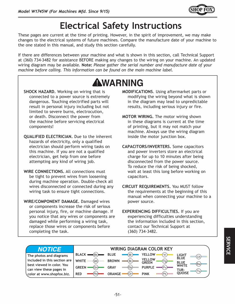
-51-
Model W1745W (For Machines Mfd. Since 9/15)SERVICE
Electrical Safety Instructions
SHOCK.HAZARD. Working on wiring that is connected to a power source is extremely dangerous. Touching electrified parts will result in personal injury including but not limited to severe burns, electrocution, or death. Disconnect the power from the machine before servicing electrical components!
QUALIFIED.ELECTRICIAN. Due to the inherent hazards of electricity, only a qualified electrician should perform wiring tasks on this machine. If you are not a qualified electrician, get help from one before attempting any kind of wiring job.
WIRE.CONNECTIONS. All connections must be tight to prevent wires from loosening during machine operation. Double-check all wires disconnected or connected during any wiring task to ensure tight connections.
WIRE/COMPONENT.DAMAGE..Damaged wires or components increase the risk of serious personal injury, fire, or machine damage. If you notice that any wires or components are damaged while performing a wiring task, replace those wires or components before completing the task.
MODIFICATIONS. Using aftermarket parts or modifying the wiring beyond what is shown in the diagram may lead to unpredictable results, including serious injury or fire.
MOTOR.WIRING. The motor wiring shown in these diagrams is current at the time of printing, but it may not match your machine. Always use the wiring diagram inside the motor junction box.
CAPACITORS/INVERTERS. Some capacitors and power inverters store an electrical charge for up to 10 minutes after being disconnected from the power source. To reduce the risk of being shocked, wait at least this long before working on capacitors.
CIRCUIT.REQUIREMENTS. You MUST follow the requirements at the beginning of this manual when connecting your machine to a power source.
EXPERIENCING.DIFFICULTIES. If you are experiencing difficulties understanding the information included in this section, contact our Technical Support at
(360) 734-3482.
The photos and diagrams included in this section are best viewed in color. You can view these pages in color at www.shopfox.biz.
BLACK
WHITE
GREEN
RED
BLUE
BROWN
GRAY
ORANGE
YELLOWYELLOWGREENPURPLE
PINK
LIGHTBLUEBLUEWHITETUR-QUOISE
WIRING DIAGRAM COLOR KEY
These pages are current at the time of printing. However, in the spirit of improvement, we may make changes to the electrical systems of future machines. Compare the manufacture date of your machine to the one stated in this manual, and study this section carefully.
If there are differences between your machine and what is shown in this section, call Technical Support at (360) 734-3482 for assistance BEFORE making any changes to the wiring on your machine. An updated wiring diagram may be available. Note: Please gather the serial number and manufacture date of your machine before calling. This information can be found on the main machine label.

-52-
Model W1745W (For Machines Mfd. Since 9/15)SE
RVIC
E
MOTOR
Ground
GND
GND
Start Capacitor
CONTROL PANEL (Viewed from Behind)
Power Indicator
Light
ON/OFF Switch
AD11-25/40-1G
Neutral
Hot
Ground
110 VAC5-15 Plug
U2
U1Z2
Z1
JKD JIEKEDACD60 250MFD
125VAC
KEDUHY-182020/12A
125/250V
Figure 80. ON/OFF switch panel backside.
STOPRead
Page 51
Before Wiring
Wiring Diagram
Figure 79. Capacitor and junction box with protective covers removed.
Motor IDJunction Box
Start Capacitor

-53-
Model W1745W (For Machines Mfd. Since 9/15)PA
RTS
44 45
4846 47
4922-1 22-2
22-4
22-7 22-6
22-5
22-3
22-822-9
2223 24 25
26
3233
34
3536
38 3940
42
43
2941
234
67 29 30
9
9
8
28
1
7
8
9
10
17
12
13
11
31
7
18
19
20
218 9
9
87
50
12
13
14
15
16
5
PARTSBase.Cabinet.&.Motor

-54-
Model W1745W (For Machines Mfd. Since 9/15)PA
RTS
Base.Cabinet.Parts.ListREF PART # DESCRIPTION REF PART # DESCRIPTION1 X1745W001 CABINET STAND 22-8 X1745W022-8 CONTACT PLATE2 X1745W002 BASE FRAME 22-9 X1745W022-9 CENTRUFUGAL SWITCH3 X1745W003 LEVELING FOOT M8-1.25 X 16 23 X1745W023 KEY 5 X 5 X 254 X1745W004 HEX BOLT M8-1.25 X 50 24 X1745W024 V-BELT A-385 X1745W005 WHEEL SPACER 25 X1745W025 MOTOR PULLEY6 X1745W006 WHEEL 26 X1745W026 SET SCREW M6-1 X 87 X1745W007 HEX NUT M8-1.25 28 X1745W028 CAP SCREW M8-1.25 X 558 X1745W008 LOCK WASHER 8MM 29 X1745W029 LOCK NUT M8-1.259 X1745W009 FLAT WASHER 8MM 30 X1745W030 PEDAL BRACKET10 X1745W010 FLANGE BOLT M8-1.25 X 16 31 X1745W031 PEDAL11 X1745W011 DUST PORT 4" 32 X1745W032 FLAT WASHER 12MM12 X1745W012 PHLP HD SCR M5-.8 X 10 33 X1745W033 E-CLIP 10MM13 X1745W013 FLAT WASHER 5MM 34 X1745W034 CLEVIS PIN, HEADLESS-GROOVED 14 X1745W014 STANDOFF-HEX M10-1.5 X 16, HEAD 64L 35 X1745W035 CAP SCREW M8-1.25 X 10015 X1745W015 FLAT WASHER 10MM 36 X1745W036 TROLLEY BRACKET16 X1745W016 LOCK WASHER 10MM 38 X1745W038 BUSHING17 X1745W017 GROMMET 50MM 39 X1745W039 INT RETAINING RING 35MM18 X1745W018 MOTOR MOUNT BRACKET 40 X1745W040 EXT RETAINING RING 15MM19 X1745W019 CABINET REAR COVER 41 X1745W041 BALL BEARING 6202ZZ20 X1745W020 HEX BOLT M8-1.25 X 30 42 X1745W042 WHEEL21 X1745W021 CARRIAGE BOLT M8-1.25 X 20 43 X1745W043 CAP SCREW M8-1.25 X 5022 X1745W022 MOTOR 1HP 120V 1-PH 44 X1745W044 WRENCH 11-13MM OPEN-ENDS22-1 X1745W022-1 MOTOR FAN COVER 45 X1745W045 WRENCH 8-10MM OPEN-ENDS22-2 X1745W022-2 MOTOR FAN 46 X1745W046 HEX WRENCH 3MM22-3 X1745W022-3 CAPACITOR COVER 47 X1745W047 HEX WRENCH 4MM22-4 X1745W022-4 MOTOR JUNCTION BOX 48 X1745W048 HEX WRENCH 5MM22-5 X1745W022-5 S CAPACITOR 250M 125V 1-3/8 X 3-1/8 49 X1745W049 HEX WRENCH 6MM22-6 X1745W022-6 BALL BEARING 6204ZZ (FRONT) 50 X1745W050 POWER CORD 14G 3W 72" 5-15P22-7 X1745W022-7 BALL BEARING 6204ZZ (REAR)
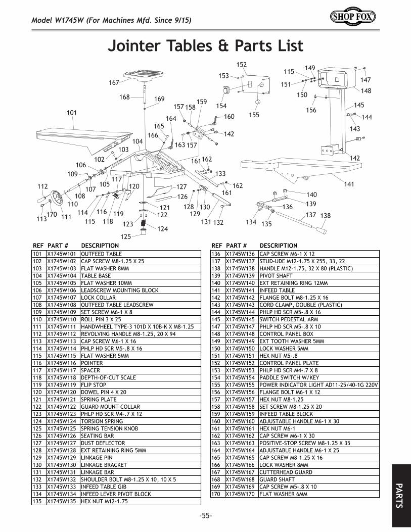
-55-
Model W1745W (For Machines Mfd. Since 9/15)PA
RTS
101
102103
104
105
106
107108
109
110
111
112
114113 115
116
117
118119
120
121122
123124
125
126127
128129
130
131 132
133
134 135
136137 138
139140
141
142143
144
145
147
148
149
150
151
152
153
154155
156157 158159
160
161162
163
162
165166
167
168 169
170
142
115
164
157
161
Jointer.Tables.&.Parts.List
REF PART # DESCRIPTION REF PART # DESCRIPTION101 X1745W101 OUTFEED TABLE 136 X1745W136 CAP SCREW M6-1 X 12102 X1745W102 CAP SCREW M8-1.25 X 25 137 X1745W137 STUD-UDE M12-1.75 X 255, 33, 22103 X1745W103 FLAT WASHER 8MM 138 X1745W138 HANDLE M12-1.75, 32 X 80 (PLASTIC)104 X1745W104 TABLE BASE 139 X1745W139 PIVOT SHAFT105 X1745W105 FLAT WASHER 10MM 140 X1745W140 EXT RETAINING RING 12MM106 X1745W106 LEADSCREW MOUNTING BLOCK 141 X1745W141 INFEED TABLE107 X1745W107 LOCK COLLAR 142 X1745W142 FLANGE BOLT M8-1.25 X 16108 X1745W108 OUTFEED TABLE LEADSCREW 143 X1745W143 CORD CLAMP, DOUBLE (PLASTIC)109 X1745W109 SET SCREW M6-1 X 8 144 X1745W144 PHLP HD SCR M5-.8 X 16110 X1745W110 ROLL PIN 3 X 25 145 X1745W145 SWITCH PEDESTAL ARM111 X1745W111 HANDWHEEL TYPE-3 101D X 10B-K X M8-1.25 147 X1745W147 PHLP HD SCR M5-.8 X 10112 X1745W112 REVOLVING HANDLE M8-1.25, 20 X 94 148 X1745W148 CONTROL PANEL BOX113 X1745W113 CAP SCREW M6-1 X 16 149 X1745W149 EXT TOOTH WASHER 5MM114 X1745W114 PHLP HD SCR M5-.8 X 16 150 X1745W150 LOCK WASHER 5MM115 X1745W115 FLAT WASHER 5MM 151 X1745W151 HEX NUT M5-.8116 X1745W116 POINTER 152 X1745W152 CONTROL PANEL PLATE117 X1745W117 SPACER 153 X1745W153 PHLP HD SCR M4-.7 X 8118 X1745W118 DEPTH-OF-CUT SCALE 154 X1745W154 PADDLE SWITCH W/KEY119 X1745W119 FLIP STOP 155 X1745W155 POWER INDICATOR LIGHT AD11-25/40-1G 220V120 X1745W120 DOWEL PIN 4 X 20 156 X1745W156 FLANGE BOLT M6-1 X 12121 X1745W121 SPRING PLATE 157 X1745W157 HEX NUT M8-1.25122 X1745W122 GUARD MOUNT COLLAR 158 X1745W158 SET SCREW M8-1.25 X 20123 X1745W123 PHLP HD SCR M4-.7 X 12 159 X1745W159 INFEED TABLE BLOCK124 X1745W124 TORSION SPRING 160 X1745W160 ADJUSTABLE HANDLE M6-1 X 30125 X1745W125 SPRING TENSION KNOB 161 X1745W161 HEX NUT M6-1126 X1745W126 SEATING BAR 162 X1745W162 CAP SCREW M6-1 X 30127 X1745W127 DUST DEFLECTOR 163 X1745W163 POSITIVE-STOP SCREW M8-1.25 X 35128 X1745W128 EXT RETAINING RING 5MM 164 X1745W164 ADJUSTABLE HANDLE M6-1 X 25129 X1745W129 LINKAGE PIN 165 X1745W165 CAP SCREW M8-1.25 X 16130 X1745W130 LINKAGE BRACKET 166 X1745W166 LOCK WASHER 8MM131 X1745W131 LINKAGE BAR 167 X1745W167 CUTTERHEAD GUARD132 X1745W132 SHOULDER BOLT M8-1.25 X 10, 10 X 5 168 X1745W168 GUARD SHAFT133 X1745W133 INFEED TABLE GIB 169 X1745W169 CAP SCREW M5-.8 X 10134 X1745W134 INFEED LEVER PIVOT BLOCK 170 X1745W170 FLAT WASHER 6MM135 X1745W135 HEX NUT M12-1.75
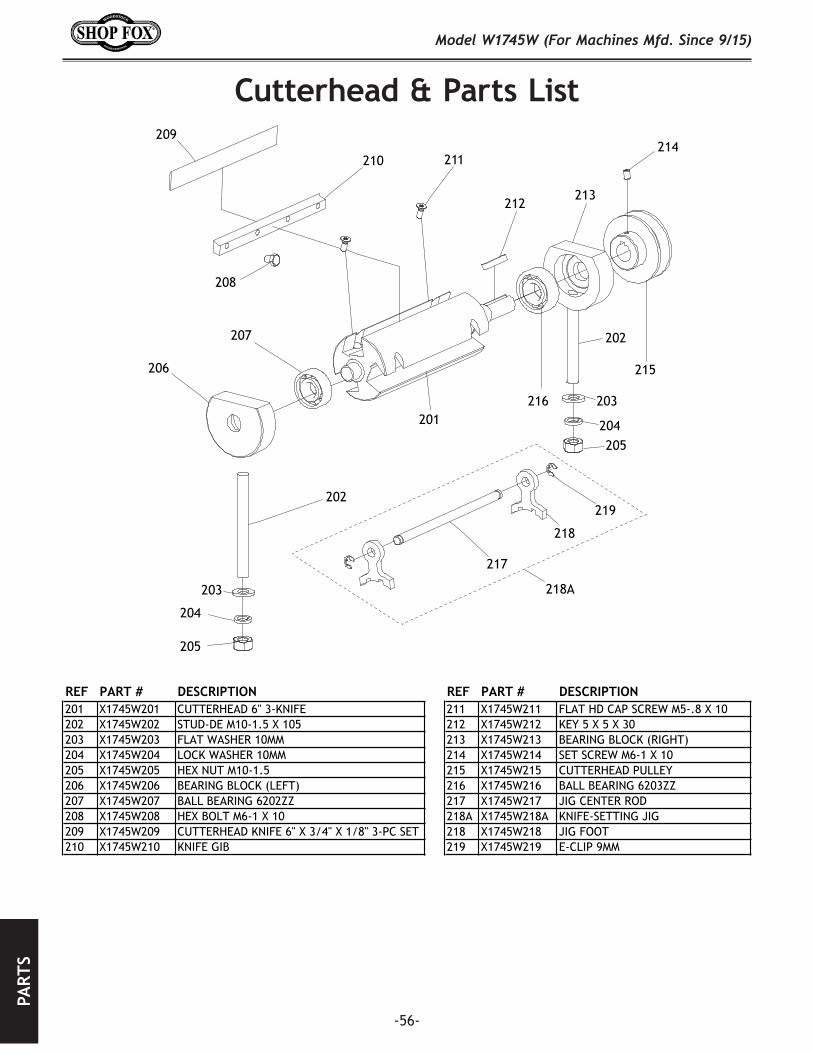
-56-
Model W1745W (For Machines Mfd. Since 9/15)PA
RTS
Cutterhead.&.Parts.List
201
202
204
205
206
207
208
209
210 211
212213
214
215
216
217
218
219
202
204205
218A203
203
REF PART # DESCRIPTION REF PART # DESCRIPTION201 X1745W201 CUTTERHEAD 6" 3-KNIFE 211 X1745W211 FLAT HD CAP SCREW M5-.8 X 10202 X1745W202 STUD-DE M10-1.5 X 10⁵ 212 X1745W212 KEY 5 X 5 X 30203 X1745W203 FLAT WASHER 10MM 213 X1745W213 BEARING BLOCK (RIGHT)204 X1745W204 LOCK WASHER 10MM 214 X1745W214 SET SCREW M6-1 X 10205 X1745W205 HEX NUT M10-1.5 215 X1745W215 CUTTERHEAD PULLEY206 X1745W206 BEARING BLOCK (LEFT) 216 X1745W216 BALL BEARING 6203ZZ207 X1745W207 BALL BEARING 6202ZZ 217 X1745W217 JIG CENTER ROD208 X1745W208 HEX BOLT M6-1 X 10 218A X1745W218A KNIFE-SETTING JIG209 X1745W209 CUTTERHEAD KNIFE 6" X 3/4" X 1/8" 3-PC SET 218 X1745W218 JIG FOOT210 X1745W210 KNIFE GIB 219 X1745W219 E-CLIP 9MM

-57-
Model W1745W (For Machines Mfd. Since 9/15)PA
RTS
Fence.and.Parts.List
301
302
303304
305 306
307
308 309
310
311
312
313
314 315
316 317 318 320
322
323
324
325326 327
328
329330
331332
333
334
335
336
337
339
340
341
311
325
325
304
315
321
REF PART # DESCRIPTION REF PART # DESCRIPTION301 X1745W301 FENCE 322 X1745W322 FENCE PIVOT SUPPORT (RIGHT)302 X1745W302 STUD-UDE M10-1.5 X 100, 30, 12 323 X1745W323 ROLL PIN 6 X 45303 X1745W303 HANDLE M10-1.5, 35 X 45 (PLASTIC) 324 X1745W324 FENCE MOUNTING PLATE304 X1745W304 HEX BOLT M8-1.25 X 25 325 X1745W325 LOCK WASHER 8MM305 X1745W305 HEX BOLT M10-1.5 X 170 326 X1745W326 CAP SCREW M8-1.25 X 25306 X1745W306 FENCE PIVOT SUPPORT (LEFT) 327 X1745W327 FENCE ADJUSTMENT RACK RAM307 X1745W307 FENCE CARRIAGE 328 X1745W328 FLAT WASHER 10MM308 X1745W308 SHOULDER BOLT M8-1.25 X 10, 10 X 5 329 X1745W329 ADJUSTABLE HANDLE M10-1.5 X 50309 X1745W309 SWING-STOP 330 X1745W330 FENCE ADJUSTMENT PINION KNOB310 X1745W310 SET SCREW M6-1 X 8 331 X1745W331 SET SCREW M10-1.5 X 16311 X1745W311 DOWEL PIN 10 X 40 332 X1745W332 CAP SCREW M8-1.25 X 20312 X1745W312 CAP SCREW M6-1 X 20 333 X1745W333 SET SCREW M8-1.25 X 16313 X1745W313 REAR PIVOT CLAMP 334 X1745W334 RAM HOUSING314 X1745W314 PIVOT SUPPORT 335 X1745W335 RAM ARM GUARD315 X1745W315 HEX NUT M8-1.25 336 X1745W336 FENCE CARRIAGE MOUNT316 X1745W316 HEX BOLT M8-1.25 X 30 337 X1745W337 CAP SCREW M8-1.25 X 35317 X1745W317 FENDER WASHER 10MM 339 X1745W339 SET SCREW M8-1.25 X 25318 X1745W318 LOCK HANDLE M10-1.5 340 X1745W340 FLAT WASHER 6MM320 X1745W320 PHLP HD SCR M6-1 X 16 341 X1745W341 CAP SCREW M6-1 X 16321 X1745W321 FLAT WASHER 6MM
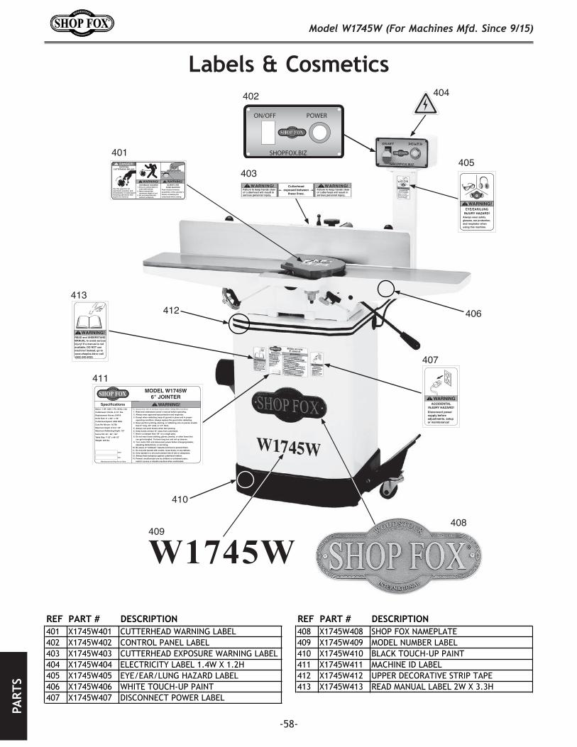
-58-
Model W1745W (For Machines Mfd. Since 9/15)PA
RTS
W1745W
Lab
els A11/27/15
MODEL W1745W6" JOINTER
Motor: 1 HP, 120V, 1-Ph, 60 Hz, 12A
Cutterhead: 3 Knife, 2-1/2" Dia.
Replacement Knives: D4616
Knife Size: 6" x 3/4" x 1/8"
Cutterhead Speed: 4900 RPM
Cuts Per Minute: 14,700
Maximum Depth of Cut: 1/8"
Maximum Rabbeting Depth: 1/2"
Fence Tilt: 45º, 90º, 135º
Table Size: 7-1/2" x 46-1/2"
Weight: 269 lbs.
Specifications WARNING! To reduce the risk of serious injury when using this machine: 1. Read and understand owner’s manual before operating. 2. Always wear approved eye protection and respirator. 3. Except when rabbeting, keep all guards in place and in proper operating condition. Always replace the guard after rabbeting. 4. Never perform jointing, planing, or rabbeting cuts on pieces smaller than 8" long, 3/4" wide, or 1/4" thick. 5. Always use push blocks when face planing. 6. Keep hands at least 12" away from cutterhead. 7. Never cut deeper than 1/8" on a single pass. 8. Do not wear loose clothing, gloves, jewelry, or other items that can get entangled. Tie back long hair and roll up sleeves. 9. Turn motor OFF and disconnect power before changing blades, adjusting tables/fence, or servicing.
.meht tneverp ot woh dna sdrazah "kcabkcik" fo erawa eB .01 .stcefed yna ro ,stonk esool ,skcarc htiw sdraob tnioj ton oD .11 .ssenpmad ro niar fo eerf tnemnorivne yrd a ni etarepo ylnO .21
13. Always feed workpiece against cutterhead rotation.14. Prevent unauthorized use by children or untrained users; restrict access or disable machine when unattended.Manufactured for Shop Fox in China
Date
S/N
COPYRIG
HT ©
WO
OD
STOCK IN
TERNA
TION
AL, IN
C.FO
R SH
OP FO
X M
AC
HIN
ES ON
LY! D
O N
OT
REPR
OD
UC
E OR
CH
AN
GE T
HIS A
RT
WO
RK
WIT
HO
UT
W
RIT
TEN
APPR
OV
AL! W
oodstock will not accept labels changed w
ithout approval. If artwork
changes are required, contact us imm
ediately at manuals@
woodstockint.com
.
120 x 163mm
40 x 245mm
***
Labels marked *** have changed since last sending
Failure to keep hands clear of cutterhead will result in serious personal injury.
Failure to keep hands clear of cutterhead will result in serious personal injury.
Cutterhead exposed between
these lines.
READ and UNDERSTANDMANUAL to avoid seriousinjury! If a manual is notavailable, DO NOT use machine! Instead, go towww.shopfox.biz or call (800) 840-8420.
WARNING!WARNINGACCIDENTAL
INJURY HAZARD!Disconnect power supply before adjustments, setup or maintenance!
155mm x 22mm
51 x 84mm51 x 84mm 51 x 84mm
105 x 54mm
36 x 32mm
COLOR CODES
DANGER PANTONE 485 C or RAL 3001
PANTONE 151 C or RAL 2005WARNING
PANTONE YELLOW CCAUTION
WARNING!EYE/EAR/LUNG
INJURY HAZARD!Always wear safety glasses, ear protection, and respirator when using this machine.
DANGER!
WARNING! WARNING!
ROTATING CUTTERHEAD BELOW!
KICKBACK HAZARD!1. Ensure outfeed table is
even with knives.2. Never exceed the
maximum depth of cut.3. Do not stand directly
behind workpiece.
ALWAYS USE PUSH BLOCKS!
Push blocks minimize possibility of the operator’s hands contacting the cutterhead while cutting.
Use this guard for all operations possible, and immediately re-install guardfollowing operations that require its removal.
Note: Labels marked *** have changed since last sending.
***
COPYRIGHT © WOODSTOCK INTERNATIONAL, INC.FOR SHOP FOX MACHINES ONLY! DO NOT REPRODUCE OR CHANGE THIS ARTWORK
WITHOUT WRITTEN APPROVAL! Woodstock will not accept labels changed without approval. If artwork changes are required, contact us immediately at
• 1:1 Scale (Labels are actual size)• Labels must be made of chemical-resistant material
W1745 Labels C (11/13/15)
Failure to keep hands clear of cutterhead will result in serious personal injury.
Failure to keep hands clear of cutterhead will result in serious personal injury.
Cutterhead exposed between
these lines.
READ and UNDERSTANDMANUAL to avoid seriousinjury! If a manual is notavailable, DO NOT use machine! Instead, go towww.shopfox.biz or call (800) 840-8420.
WARNING!WARNINGACCIDENTAL
INJURY HAZARD!Disconnect power supply before adjustments, setup or maintenance!
155mm x 22mm
51 x 84mm51 x 84mm 51 x 84mm
105 x 54mm
36 x 32mm
COLOR CODES
DANGER PANTONE 485 C or RAL 3001
PANTONE 151 C or RAL 2005WARNING
PANTONE YELLOW CCAUTION
WARNING!EYE/EAR/LUNG
INJURY HAZARD!Always wear safety glasses, ear protection, and respirator when using this machine.
DANGER!
WARNING! WARNING!
ROTATING CUTTERHEAD BELOW!
KICKBACK HAZARD!1. Ensure outfeed table is
even with knives.2. Never exceed the
maximum depth of cut.3. Do not stand directly
behind workpiece.
ALWAYS USE PUSH BLOCKS!
Push blocks minimize possibility of the operator’s hands contacting the cutterhead while cutting.
Use this guard for all operations possible, and immediately re-install guardfollowing operations that require its removal.
Note: Labels marked *** have changed since last sending.
***
COPYRIGHT © WOODSTOCK INTERNATIONAL, INC.FOR SHOP FOX MACHINES ONLY! DO NOT REPRODUCE OR CHANGE THIS ARTWORK
WITHOUT WRITTEN APPROVAL! Woodstock will not accept labels changed without approval. If artwork changes are required, contact us immediately at
• 1:1 Scale (Labels are actual size)• Labels must be made of chemical-resistant material
W1745 Labels C (11/13/15)
SHOPFOX.BIZ
ON/OFF POWER
W1745W Labels B5/21/15
COPYRIGHT © WOODSTOCK INTERNATIONAL, INC.WARNING: THIS LABEL ARTWORK SHALL NOT BE REPRODUCED AND IS ONLY TO BE USED
ON WOODSTOCK MACHINES.
193 x 104mm
Failure to keep hands clear of cutterhead will result in serious personal injury.
Failure to keep hands clear of cutterhead will result in serious personal injury.
Cutterhead exposed between
these lines.
READ and UNDERSTANDMANUAL to avoid seriousinjury! If a manual is notavailable, DO NOT use machine! Instead, go towww.shopfox.biz or call (800) 840-8420.
WARNING!WARNINGACCIDENTAL
INJURY HAZARD!Disconnect power supply before adjustments, setup or maintenance!
155mm x 22mm
51 x 84mm51 x 84mm 51 x 84mm
105 x 54mm
36 x 32mm
COLOR CODES
DANGER PANTONE 485 C or RAL 3001
PANTONE 151 C or RAL 2005WARNING
PANTONE YELLOW CCAUTION
WARNING!EYE/EAR/LUNG
INJURY HAZARD!Always wear safety glasses, ear protection, and respirator when using this machine.
DANGER!
WARNING! WARNING!
ROTATING CUTTERHEAD BELOW!
KICKBACK HAZARD!1. Ensure outfeed table is
even with knives.2. Never exceed the
maximum depth of cut.3. Do not stand directly
behind workpiece.
ALWAYS USE PUSH BLOCKS!
Push blocks minimize possibility of the operator’s hands contacting the cutterhead while cutting.
Use this guard for all operations possible, and immediately re-install guardfollowing operations that require its removal.
Note: Labels marked *** have changed since last sending.
***
COPYRIGHT © WOODSTOCK INTERNATIONAL, INC.FOR SHOP FOX MACHINES ONLY! DO NOT REPRODUCE OR CHANGE THIS ARTWORK
WITHOUT WRITTEN APPROVAL! Woodstock will not accept labels changed without approval. If artwork changes are required, contact us immediately at
• 1:1 Scale (Labels are actual size)• Labels must be made of chemical-resistant material
W1745 Labels C (11/13/15)
401
402
403
404
405
407
408409
410
411
412413
406
Labels.&.Cosmetics
REF PART # DESCRIPTION REF PART # DESCRIPTION401 X1745W401 CUTTERHEAD WARNING LABEL 408 X1745W408 SHOP FOX NAMEPLATE402 X1745W402 CONTROL PANEL LABEL 409 X1745W409 MODEL NUMBER LABEL403 X1745W403 CUTTERHEAD EXPOSURE WARNING LABEL 410 X1745W410 BLACK TOUCH-UP PAINT404 X1745W404 ELECTRICITY LABEL 1.4W X 1.2H 411 X1745W411 MACHINE ID LABEL405 X1745W405 EYE/EAR/LUNG HAZARD LABEL 412 X1745W412 UPPER DECORATIVE STRIP TAPE406 X1745W406 WHITE TOUCH-UP PAINT 413 X1745W413 READ MANUAL LABEL 2W X 3.3H407 X1745W407 DISCONNECT POWER LABEL

-59-
Model W1745W (For Machines Mfd. Since 9/15)PA
RTS

tape along edges--please do not staple
Fold along dotted lIne
Fold along dotted lIne
Woodstock international inc. p.o. box 2309 bellingham, Wa 98227-2309
placestampHere

WARRANTYWoodstock International, Inc. warrants all Shop Fox machinery to be free of defects from workmanship and materials for a period of two years from the date of original purchase by the original owner. This warranty does not apply to defects due directly or indirectly to misuse, abuse, negligence or accidents, lack of maintenance, or reimbursement of third party expenses incurred.
Woodstock International, Inc. will repair, replace, or arrange for a dealer refund, at its expense and option, the Shop Fox machine or machine part proven to be defective for its designed and intended use, provided that the original owner returns the product prepaid to an authorized warranty or repair facility as designated by our Bellingham, Washington office with proof of their purchase of the product within two years, and provides Woodstock International, Inc. reasonable opportunity to verify the alleged defect through inspection. If it is determined there is no defect, or that the defect resulted from causes not within the scope of Woodstock International Inc.'s warranty, then the original owner must bear the cost of storing and returning the product.
This is Woodstock International, Inc.’s sole written warranty and any and all warranties that may be implied by law, including any merchantability or fitness, for any particular purpose, are hereby limited to the duration of this written warranty. We do not warrant that Shop Fox machinery complies with the provisions of any law, acts or electrical codes. We do not reimburse for third party repairs. In no event shall Woodstock International, Inc.’s liability under this limited warranty exceed the purchase price paid for the product, and any legal actions brought against Woodstock International, Inc. shall be tried in the State of Washington, County of Whatcom. We shall in no event be liable for death, injuries to persons or property or for incidental, contingent, special or consequential damages arising from the use of our products.
Every effort has been made to ensure that all Shop Fox machinery meets high quality and durability standards. We are commited to continuously improving the quality of our products, and reserve the right to change specifications at any time.

High Quality Machines and Tools
Woodstock International, Inc. carries thousands of products designed to meet the needs of today's woodworkers and metalworkers.
Ask your dealer about these fine products: